

Page 1
16
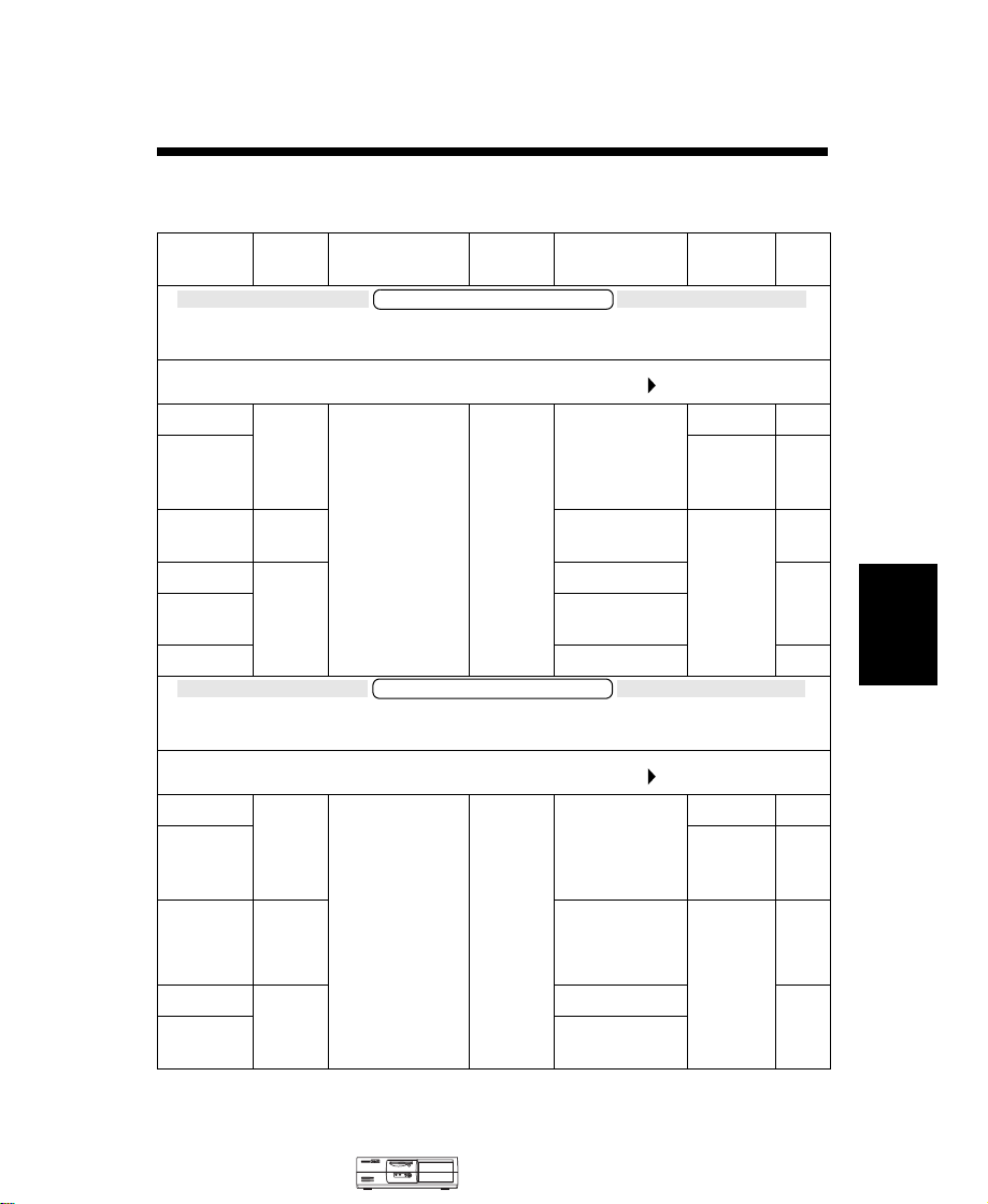
HP Vectra VLi 8 PC
Models and Accessories
Product
Number
D7941A/T 6.4 GB
D7942A/T 3COM
D7943A/T 8.4 GB
D7944T 6.4 GB
D7945A/T 32 ✕ Max IDE
D8794A no DOS
Hard
Drive
100MHz System Bus Speed, and 512 KB Level 2 Cache Memory
IDE
IDE
IDE
100 MHz System Bus Speed, and 512 KB Level 2 Cache Memory
Video
Controller
Models with Intel Pentium II Processor,
HP Vectra VLi 8 PC 400/100 (CPL: 03/99 )
Integrated
Matrox
MGA-G200 AGP
(8 MB SGRAM
fitted, not
upgradeable)
Models with Intel Pentium III Processor,
Std.
RAM
Vectra VLi 8 PC
64 MB
SDRAM
100 MHz
Vectra VLi 8 PC
Multi-media LAN OS
no no W95
32 ✕ Max IDE
CD-ROM
no NT
CD-ROM
3C905BTX
no W95
NT
4.0
WS
4.0
WS
1
16
HP Vectra VLi 8 PC 450/100 (CPL: 03/99 )
D7951A/T 6.4 GB
D7952A/T 3COM
D7953A/T 8.4 GB
D7954T 6.4 GB
D7955A/T 32 ✕ Max IDE
Medium-Profile
Desktop Vectras
IDE
IDE
IDE
Integrated
Matrox
MGA-G200 AGP
(8 MB SGRAM
fitted, not
upgradeable)
64 MB
SDRAM
100 MHz
no no W95
3C905BTX
32 ✕ Max IDE
CD-ROM
no NT
CD-ROM
HP Vectra VLi 8 PC 16-1
no W95
NT
4.0
WS
4.0
WS
Page 2
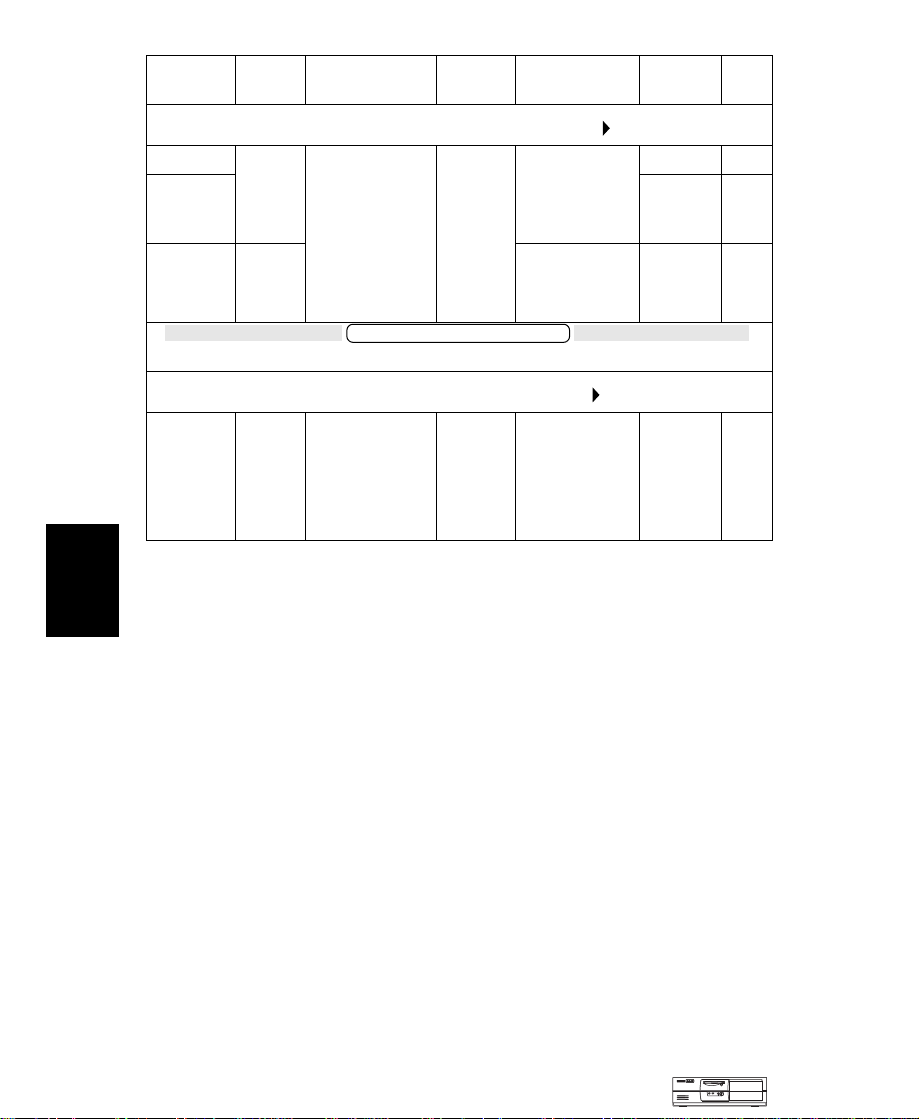
HP Vectra VLi 8 PC
Product
Number
Hard
Drive
Video
Controller
Std.
RAM
Multi-media LAN OS
1
16
HP Vectra VLi 8 PC 500/100
D7961A/T
D7962A/T
D7963A/T
D7950E
1. Operating system preloaded on these models, as indicated in the table.
2. Channel Assembly Program (CAP) models: Processor speed, hard disk size, and memory is
6.4 GB
IDE
8.4 GB
IDE
Models with User Defined Processor, Main Memory, and Hard Disk
User
defined
user defined.
Integrated
Matrox
MGA-G200 AGP
(8 MB SGRAM
fitted, not
upgradeable)
HP Vectra VLi 8 PC /xxx
Integrated
Matrox
MGA-G200 AGP
(8 MB SGRAM
fitted, not
upgradeable)
64 MB
SDRAM
100 MHz
Vectra VLi 8 PC
User
defined
(CPL: 03/99 )
no no W95
3COM
3C905BTX
32 ✕ Max IDE
CD-ROM
2
(CPL: 03/99 )
User defined User
no W95
defined
Note
All model have an integrated full-duplex PCI audio controller.
NT
4.0
WS
None
Supported Accessories
32-MB kit 32-bit SDRAM, 100 MHz non-ECC main memory module D6501A/T
32-MB kit 32-bit SDRAM, 100 MHz non-ECC main memory module
(pack of 20)
64-MB kit 32-bit SDRAM, 100 MHz non-ECC main memory module D6502A/T
64-MB kit 32-bit SDRAM, 100 MHz non-ECC main memory module
(pack of 20)
128-MB, 32-bit SDRAM, 100 MHz non-ECC main memory module D6503A/T
256-MB, 32-bit SDRAM, 100 MHz ECC main memory module D6743A/T
Documentation
User’s Guide
16-2 HP Vectra VLi 8 PC
Manual Kit D7940A
Medium-Profile
Desktop Vectras
D6504A/T
D6505A/T
Page 3

HP Vectra VLi 8 PC
Input Devices
HP Standard Keyboard C4735A
HP Scrolling Mouse C4736A
Video Displays
All current HP Displays (see the HP Vectra Accessory Service Handbook)
Mass Storage
4.3-GB IDE hard disk D8371A
6.4-GB IDE hard disk D8372A
8.4-GB IDE hard disk D8373A
HP 100 MB Atapi II Iomega ZIP drive D6650A
HP 100 MB Atapi II Iomega ZIP drive (pack of 10) D6651A
Multimedia
32✕ Max IDE CD-ROM drive (pack of 10) D6656A
32✕ Max IDE CD-ROM drive D4384A
Multimedia sound accessory kit (16-bit audio board, cables, and software) -
pack of 10
Multimedia sound accessory kit (32✕ Max CD-ROM drive, 16-bit audio
board, headphones, cables, and software)
D5183A
D6657A
Data Communications and LAN Adapter Boards
HP 56K V90 PCI Fax Modem D7808A
HP 10/100 3Com 3C905B-TX, 10/100BT Ethernet card D7504A
HP 10/100 3Com 3C905B-TX, 10/100BT Ethernet card (pack of 10) D7505A
HP 10/100 Intel PRO/100+, 10/100BT Management adapter D7506A
HP 10/100 Intel PRO/100+, 10/100BT Management adapter (pack of 10) D7507A
Security
HP Master Pass Key System Kit D6655A
HP Master Pass Key D6658A
HP Locks for Master Pass Key System (pack of 50) D6659A
Medium-Profile
Desktop Vectras
HP Vectra VLi 8 PC 16-3
16
Page 4
HP Vectra VLi 8 PC
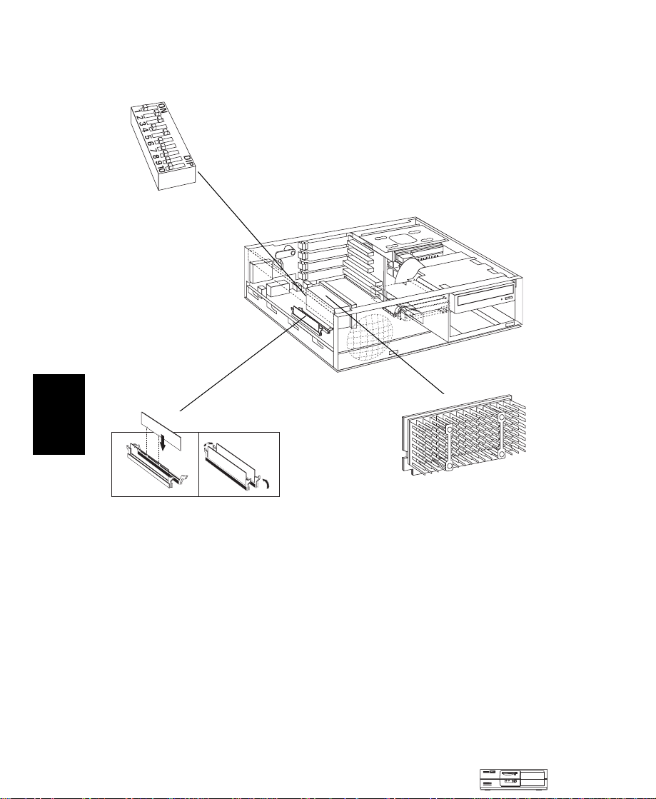
System Board, BIOS, and Memory
16
System Board
Switches:
table on the next page.
Main Memory:
Two DIMM sockets which support
up to a maximum of 512 MB.
Install 32 MB, 64 MB, 128 MB or
256 MB 100 MHz SDRAM modules.
See the
Processor:
or Pentium III SECC2
package with integrated
heatsink and level-2
cache memory.
Pentium II
16-4 HP Vectra VLi 8 PC
Medium-Profile
Desktop Vectras
Page 5
HP Vectra VLi 8 PC
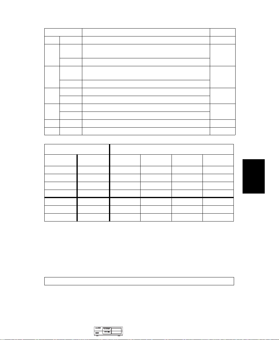
System Board Switches
Switch Function Default
1—
2
3
4
5
6-9 —
10 —
RESERVED — Do Not Use
On Crash recovery mode: forces booting in the BIOS boot
block area
Off Normal operation
On Normal operation (keyboard space-bar power-on
enabled)
Off Disables keyboard power- on
On Clears User and Administrator passwords
Off Normal operation
On Clears CMOS (to reload the
Off Normal operation
Processor frequency, see the following table
RESERVED — Do Not Use
Setup
program defaults)
Off
Off
On
Off
Off
—
Off
System Frequency
Bus 100 MHz Bus 66 MHz
2
350 MHz
400 MHz 266
450 MHz 300
500 MHz 333
Reserved 366
Reserved 400
Reserved 433
1. System and processor frequency is automatically determined by the type of processor.
2. These options are not yet available in any model of the HP Vectra VLi 8 at the time of
printing. This information is provided for completeness only.
1
6789
2332 MHz Off On Off On
2
MHz On Off On On
2
MHz Off Off On On
2
MHz On Off Off On
2
MHz Off Off Off On
2
MHz On On On Off
2
MHz Off On On Off
Switch
BIOS History
For the latest BIOS, the flasher utility program, and the BIOS history refer to the
HP World Wide Web site.
http://www.hp.com/go/vectrasupport/
16
Medium-Profile
Desktop Vectras
HP Vectra VLi 8 PC 16-5
Page 6
HP Vectra VLi 8 PC
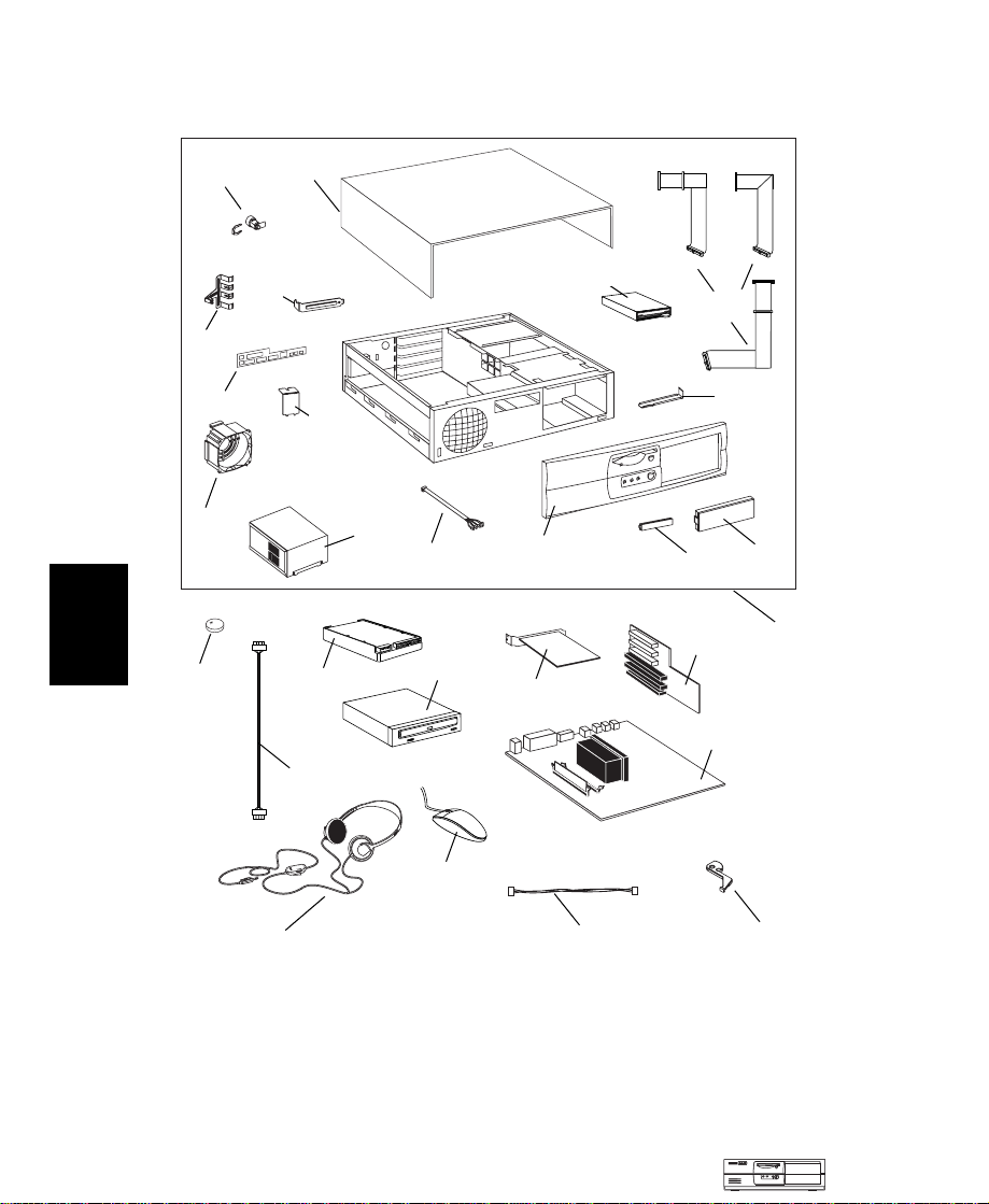
Part Numbers
16
k
h
n
m
2
a
g
i
l
c
5
3
6
10
o
j
f
b
e
8
d
1
9
4
16-6 HP Vectra VLi 8 PC
7
11
Medium-Profile
Desktop Vectras
12
Page 7
HP Vectra VLi 8 PC
Parts List for HP Vectra VLi 8 PC
Item Description Repl.
Box assembly:
1
a Cover assembly
b Bezel assembly
c Status panel assembly
d Blank filler (5.25 inch)
e Blank filler (3.5 inch)
f CD frame rail
g I/O blank panel
hI/O locker
i AGP blank panel
j HDD, FDD and CD-ROM cable kit
k Master key lock
l Power supply
m Fan assembly
n Rear bezel
o Floppy disk drive (bezel-less)
not
pAirflow guide
shown
2 Battery type CR2032
3 CD-ROM to audio connector cable
Headphones 5182-3552 —
4
IDE hard disk drive
5
6.4 GB
8.4 GB
13.5 GB
32 ✕ Max IDE CD-ROM drive — D4385-69001
6
7 Enhanced mouse with scroll/zoom wheel
Standard keyboard
Standard keyboard (Japan)
Multimedia keyboard
8 Backplane board
9 System board
10 3Com 3C905B-TX LAN board
or Intel PRO/100+ LAN board
11 3COM Wake on LAN Cable
Mini NLX board extractor
12
1. For optional disk drive information, see the Accessory Service Handbook.
2. Where “xx” is the code for your national keyboard (see the Accessory Service Handbook).
1
Part Number
5064-9152
5064-7470
5064-7471
5064-9129
5042-3073
5042-3086
5002-6213
5002-3841
5002-4795
5002-6211
5064-9135
5064-2645
0950-3472
5064-9149
5064-9127
D2035-60391
tbd
1420-0356 —
5182-1857 —
—
—
—
C4736-60101 —
C4735-603xx2—
C4732-60324 —
C4734-605xx2—
5064-7455 —
See PC’s system board parts list
5064-6787 —
5064-7434 —
5183-2769 —
5064-9114
Exchange
Part Number
—
—
—
—
—
—
—
—
—
—
—
—
—
—
—
—
—
D8372-69001
D8373-69001
D8435-69001
—
16
Medium-Profile
Desktop Vectras
HP Vectra VLi 8 PC 16-7
Page 8
16
HP Vectra VLi 8 PC
System Board Parts List for HP Vectra VLi 8 PC
Description Repl.
System board:
Vectra VLi 8 system board with Matrox
MGA-G200 video controller and audio
subsystem
Processors (SECC2 package):
Intel Pentium II 400/100 512KB L2 cache — D7645-69001
Intel Pentium III 450/100 512KB L2 cache — D7946-69001
Intel Pentium III 500/100 512KB L2 cache — D7957-69001
Main memory modules:
1 ✕ 64-MB, 100 MHz noon-ECC SDRAM D6502-63001 —
Part Number
— D4066-69001
Manuals and Documentation for HP Vectra VLi 8 PC
User’s Guide Manual Kit
Troubleshooting and Upgrade Guide
Technical Reference Manual: hardware and BIOS
1. Electronic file available on HP’s Web site.
Notes:
____________________________________________________________________
Exchange
Part Number
D7940A
no number
no number
1
1
____________________________________________________________________
____________________________________________________________________
____________________________________________________________________
____________________________________________________________________
____________________________________________________________________
____________________________________________________________________
____________________________________________________________________
16-8 HP Vectra VLi 8 PC
Medium-Profile
Desktop Vectras
Page 9
2 How to Install and Replace Components In Your Desktop PC
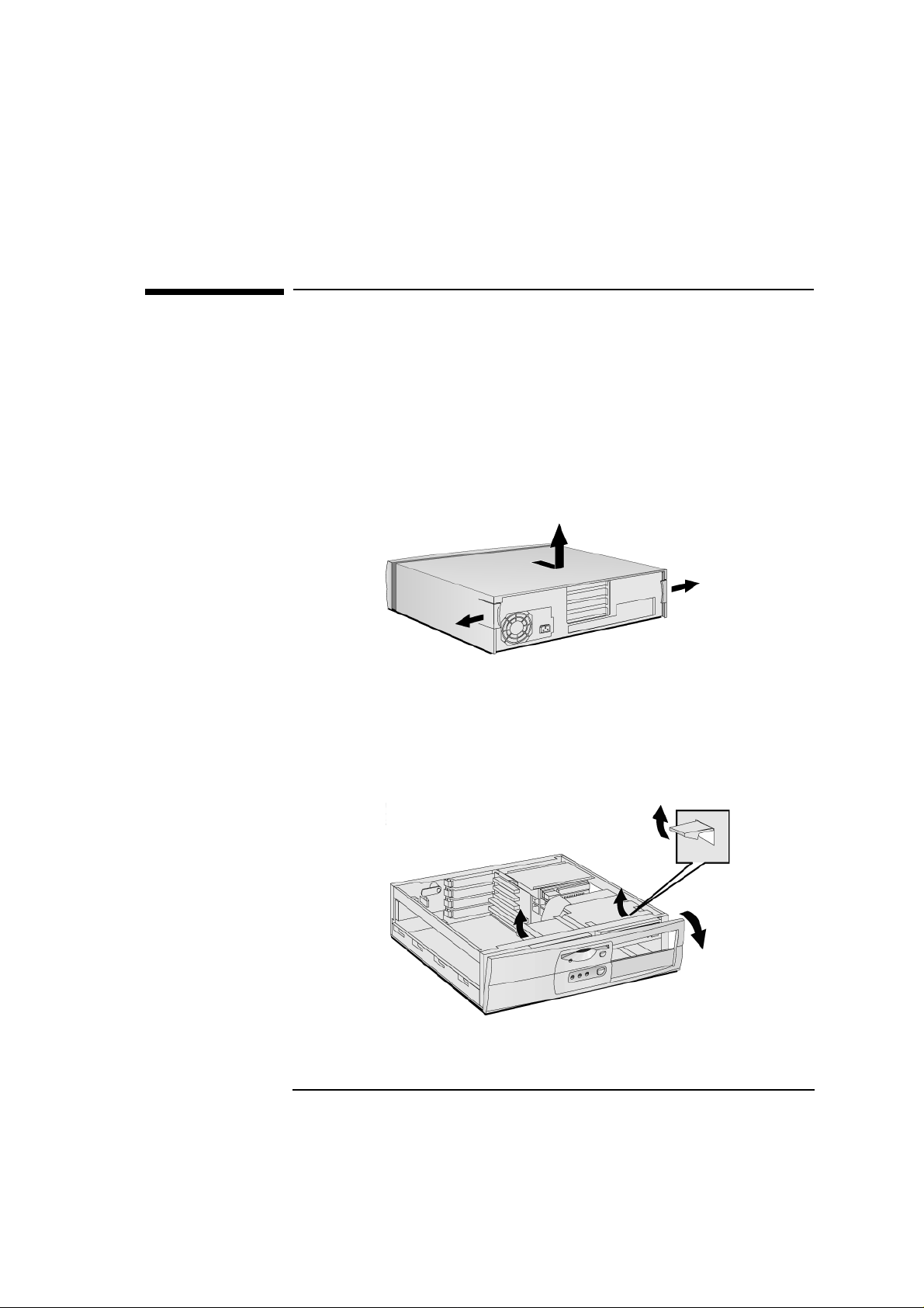
Removing and Replacing the Cover
Removing and Replacing the Cover
Removing the Cover
Switch off the monitor and PC, disconnect all power cords and any
1
telecommunication cables.
If necessary, unlock the cover (with the key) at the rear of the PC.
2
Open the rear catches
3
Remove the front panel.
4
➊ and remove the cover ➋.
➋
➊
➊
51
Page 10
2 How to Install and Replace Components In Your Desktop PC
Removing and Replacing the Cover
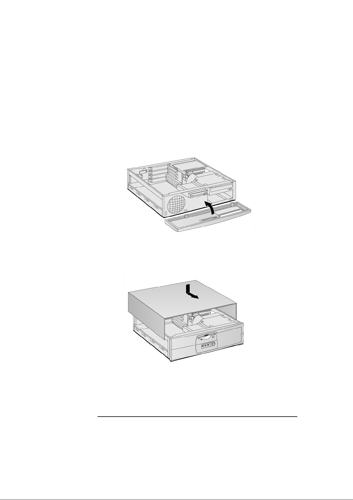
Replacing the Cover
Ensure that all internal cables are properly connected and safely
1
routed.
Replace the front panel.
2
Lower the cover and slide it into position.
3
If required, lock the cover (with the key) at the rear of the PC.
4
52
Page 11
2 How to Install and Replace Components In Your Desktop PC
The Label Inside Your PC
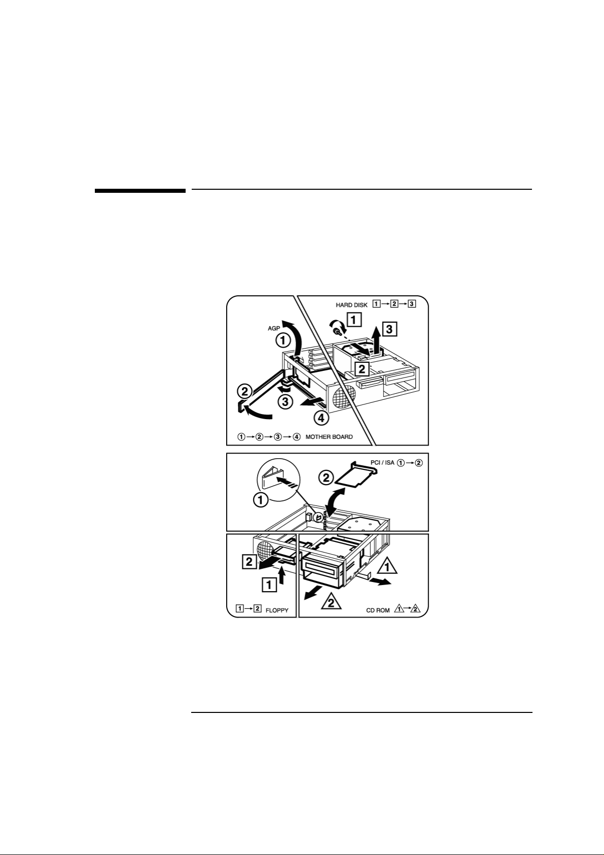
The Label Inside Your PC
Inside, your PC contains a label that can be used as a simplified guide
to help you install accessories and replace components.
Shows how to remove
the system board
(step 1 does not apply to
your PC model)
Shows how to remove
the floppy drive
Shows how to
remove the hard
disk drive
Shows how to add an
accessory board
Shows how to remove
the front drive bay
53
Page 12

2 How to Install and Replace Components In Your Desktop PC
Upgrading the Main Memory
Upgrading the Main Memory
NOTE Use only HP memory modules provided for your PC model. The use of
other memory modules is not supported. For information about
supported HP accessories, connect to the web site
www.hp.com/go/vectraaccessories.
You can install up to a total of 512 MB (two 256 MB modules). Main
memory is available in 100 MHz modules of 32 MB, 64 MB, 128 or
256 MB. (Although the 256 MB memory modules are ECC, the ECC
feature is not used by this PC.)
Location of Main Memory
(modules can be installed in
either slot)
Remove the PC’s cover (described in this chapter).
1
Line up the two side notches correctly and insert the new memory
2
module. (You can use either slot.)
Replace the cover (described in this chapter).
3
54
Page 13
2 How to Install and Replace Components In Your Desktop PC
Upgrading and Installing Mass Storage Devices
Upgrading and Installing Mass Storage Devices
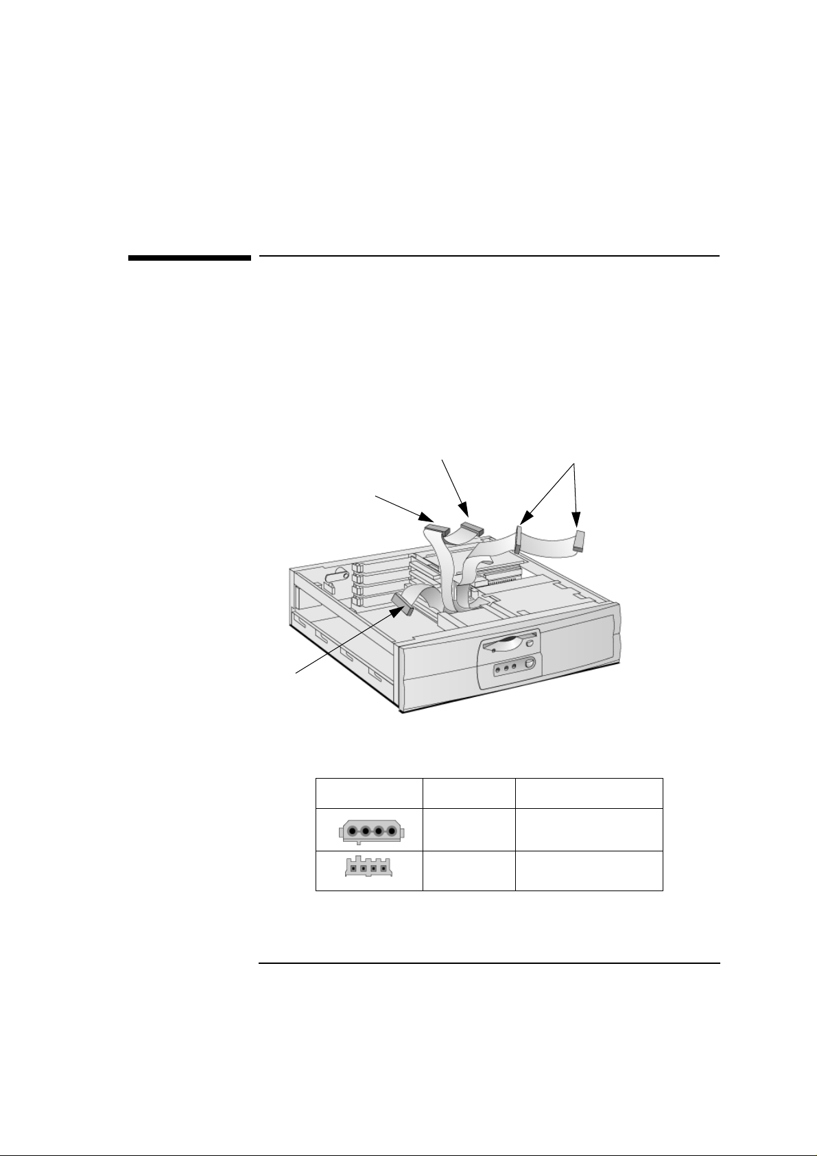
Drive Connectors
Internal drives, such as hard disk drives, DVD drives, and CD-ROM
drives, must be connected to data and power cables. When replacing
these drives, ensure you use the correct data and power connectors.
Floppy drive
Master (boot) hard disk drive
2nd hard disk drive
Power Connectors Number Use for
5
(3 devices max.)
CD-ROM, DVD or Zip drive
Hard disk drives, DVD drives,
CD-ROM drives, Zip drives
(you can use
either connector)
1
Floppy disk drive
55
Page 14

2 How to Install and Replace Components In Your Desktop PC
Upgrading and Installing Mass Storage Devices
Which Data Connectors
to Use
Before Installing an IDE
Hard Disk
There are three data cables inside your PC. Two of these are for IDE
devices.
An Enhanced Ultra ATA IDE (Integrated Drive Electronics) hard
•
disk drive cable.
For optimum performance, use this cable to connect the Ultra ATA
IDE hard disk drive.
A second IDE drive cable that supports two IDE devices. If you
•
install a CD-ROM drive, a DVD drive or a Zip drive, connect it to this
cable.
The third cable is non-IDE and has one connector for a floppy drive.
•
Up to three IDE devices can be connected to the system board using
the IDE data cables.
Refer to the drive’ s installation guide to see if you must set jumpers or if
there is a special installation procedure to follow.
56
Page 15

2 How to Install and Replace Components In Your Desktop PC
Upgrading and Installing Mass Storage Devices
Upgrading the Hard Disk Drive
CAUTION Handle the hard disk drive with care. Avoid shocks and violent
movement as this can cause damage to the hard disk drive’s internal
components.
Make sure that you back up your files before you install a hard disk
drive. Refer to your operating sy stem documentation for information on
how to do this.
You can replace your PC’s hard disk drive with a larger one. To do this:
Remove the computer’s cover (described in this chapter).
1
Remove the drive’s connectors.
2
Remove the retaining screw
3
➋
Loosen the tray’s four screws and remove the old hard drive.
4
➊ and slide out the drive tray ➋.
➊
57
Page 16

2 How to Install and Replace Components In Your Desktop PC
Upgrading and Installing Mass Storage Devices
5 Align the new hard drive in the tray (with the correct orientation)
and tighten the screws.
6 Replace the drive tray
➊
➊ and retaining screw ➋.
➋
7 Attach the data and power connectors.
8 Replace the cover (described in this chapter).
9 Verify the new configuration by checking the HP Summary Screen.
To access the HP Summary Screen, press
Esc when the V ectra logo
appears during startup.
NOTE Ensure that you have installed all the required operating system and HP
drivers on the newly installed drive. To reinstall operating system and
HP drivers, use the Diagnostics & Recovery CD-ROM provided with
the PC. In addition, you can find the most up-to-date versions of HP
drivers on HP’s Web site at: www.hp.com/go/vectrasupport
58
.
Page 17

2 How to Install and Replace Components In Your Desktop PC
Upgrading and Installing Mass Storage Devices
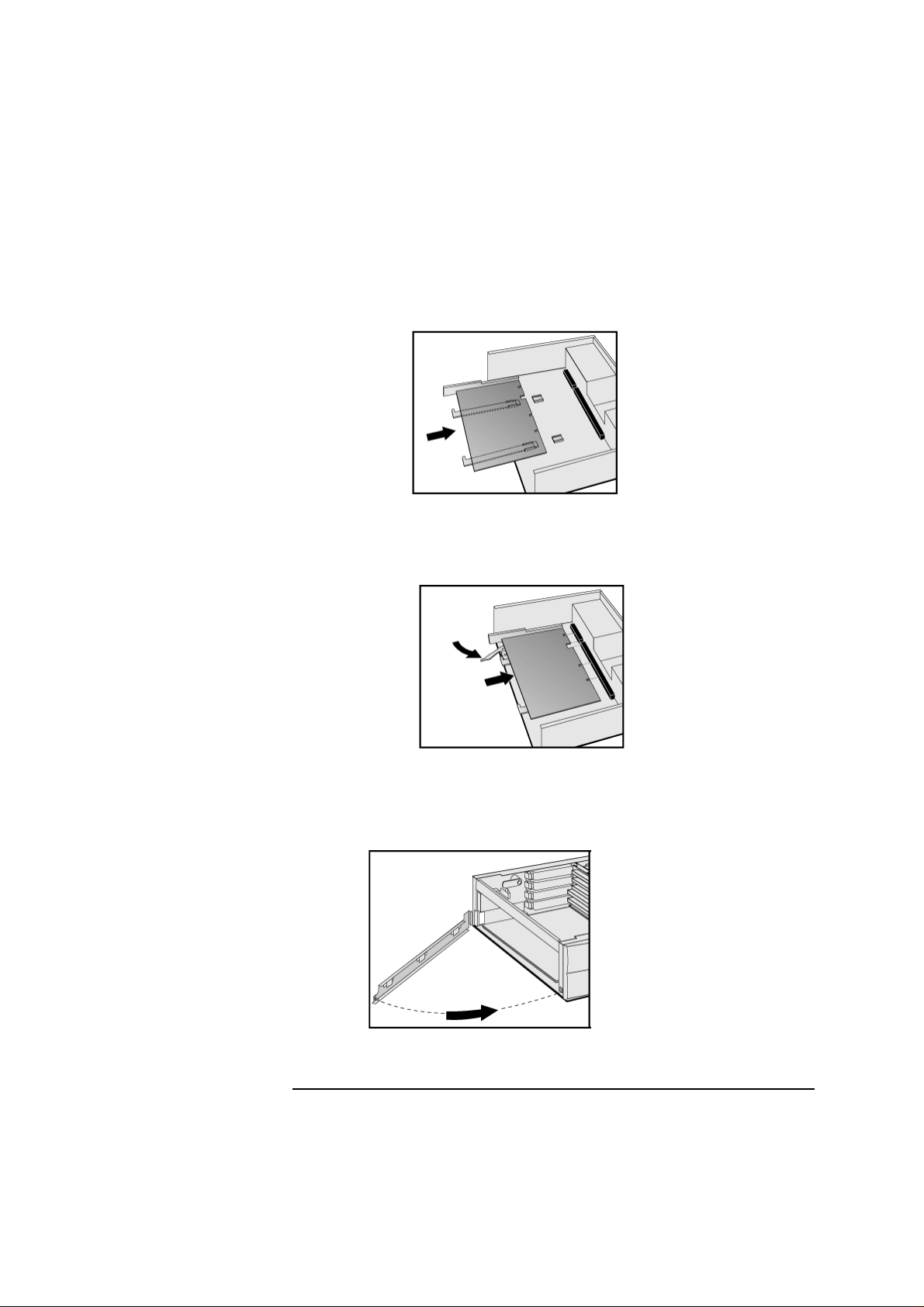
Installing a Second Hard Disk Drive
CAUTION Handle the hard disk drive with care. Avoid shocks and violent
movement as this can cause damage to the hard disk drive’s internal
components.
Make sure that you back up your files before you install a hard disk
drive. Refer to your operating sy stem documentation for information on
how to do this.
You can install a second hard disk drive in the lower front shelf of your
desktop PC.
Remove the computer’s cover (described in this chapter).
1
If there is already a drive installed in the front bay, remove its power
2
and data connectors (so that you can remove the drive bay).
Pull out the sliding latch
3
➊ and remove the drive bay ➋.
➊
➋
Align the new device in the bay (with the correct orientation) and
4
secure it with the screws provided.
59
Page 18

2 How to Install and Replace Components In Your Desktop PC
Upgrading and Installing Mass Storage Devices
5 Slide the drive bay back into the PC (ensuring the bottom catches
engage properly) and replace the sliding latch.
➊
➋
6 Attach all data and power connectors.
7 Replace the cover (described in this chapter).
8 Verify the new configuration by checking the HP Summary Screen.
To access the HP Summary Screen, press
Esc when the V ectra logo
appears during startup.
NOTE Ensure that you have installed all the required operating system and HP
drivers on the newly installed drive. To reinstall operating system and
HP drivers, use the Diagnostics & Recovery CD-ROM provided with
the PC. In addition, you can find the most up-to-date versions of HP
drivers on HP’s Web site at: www.hp.com/go/vectrasupport
.
60
Page 19

2 How to Install and Replace Components In Your Desktop PC
Upgrading and Installing Mass Storage Devices
Installing Removable Media Devices
The PC has an integrated Enhanced IDE controller which supports up
to four IDE devices. Removable media IDE devices, such as CD-ROM
drives, DVD drives, tape drives and Zip drives, require front access.
You can install a removable media IDE drive in an empty front shelf.
Refer to the drive’s manual to see if you must set jumpers or if there is
a special installation procedure to follow.
Remove the computer’s cover (described in this chapter).
1
If there is already a drive installed in the front bay, remove its power
2
and data connectors (so that you can remove the drive bay).
Pull out the sliding latch
3
➊ and remove the drive bay ➋.
➊
➋
Align the new device in the bay (with the correct orientation) and
4
secure it with the screws provided.
61
Page 20

2 How to Install and Replace Components In Your Desktop PC
Upgrading and Installing Mass Storage Devices
5 Slide the drive bay back into the PC (ensuring the bottom catches
engage properly) and replace the sliding latch.
Audio
Connector
(optional)
➊
➋
6 Attach all data and power connectors. If you are installing a CD-ROM
or DVD drive, connect the audio cable too.
7 Replace the cover (described in this chapter).
8 Verify the new configuration by checking the HP Summary Screen.
To access the HP Summary Screen, press
Esc when the V ectra logo
appears during startup.
62
Page 21

2 How to Install and Replace Components In Your Desktop PC
Upgrading and Installing Mass Storage Devices
Configuring an IDE Device After Installation
After installing any device, you will need to verify that your PC has
correctly identified the new configuration, by viewing the HP Summary
Screen. If the configuration is not correct, run the Setup program to
configure the device. To enter the Setup program, press
startup.
IDE drives are automatically detected by the Setup program. However,
a newly installed device may require that you install an appropriate
device driver. Refer to your operating system documentation for
details. You can obtain the latest drivers from HP’s Web site at:
F2 during
www.hp.com/go/vectrasupport
.
63
Page 22

2 How to Install and Replace Components In Your Desktop PC
Replacing the Floppy Drive
Replacing the Floppy Drive
Remove the computer’s cover (described in this chapter).
1
Remove the drive’s connectors.
2
Lift the latch
3
Remove the tray’s screws and remove the old floppy drive.
4
Align the new floppy drive in the tray (with the correct orientation)
5
➊ and slide out the floppy drive tray ➋.
➊
➋
and replace the screws.
Slide the floppy drive tray back into the PC.
6
Attach the data and power connectors.
7
Replace the cover (described in this chapter).
8
64
Page 23

2 How to Install and Replace Components In Your Desktop PC
Installing Accessory Boards
Installing Accessory Boards
Accessory Board Slots
The PC has four accessory board slots.
NOTE Use only XT format ISA accessory boards (width less than 10.4 cm or
4.09 inches).
Accessory Board Connectors
Physical Slot 1
Physical Slot 2
Physical Slot 3 (Combo)
Physical Slot 4
•
•
•
•
PCI 2
PCI 3
PCI 4
{
Physical slot 1 (the top slot) can be used for a full-length 32-bit PCI
board.
Physical slot 2 can be used for a full-length 32-bit PCI board.
Physical slot 3 is a combo slot and can be used either for a full-length
32-bit PCI or a full-length XT format 16-bit ISA board.
Physical slot 4 (the bottom slot) can be used for a full-length XT
format 16-bit ISA board.
ISA 1
ISA 2
65
Page 24
2 How to Install and Replace Components In Your Desktop PC
Installing Accessory Boards
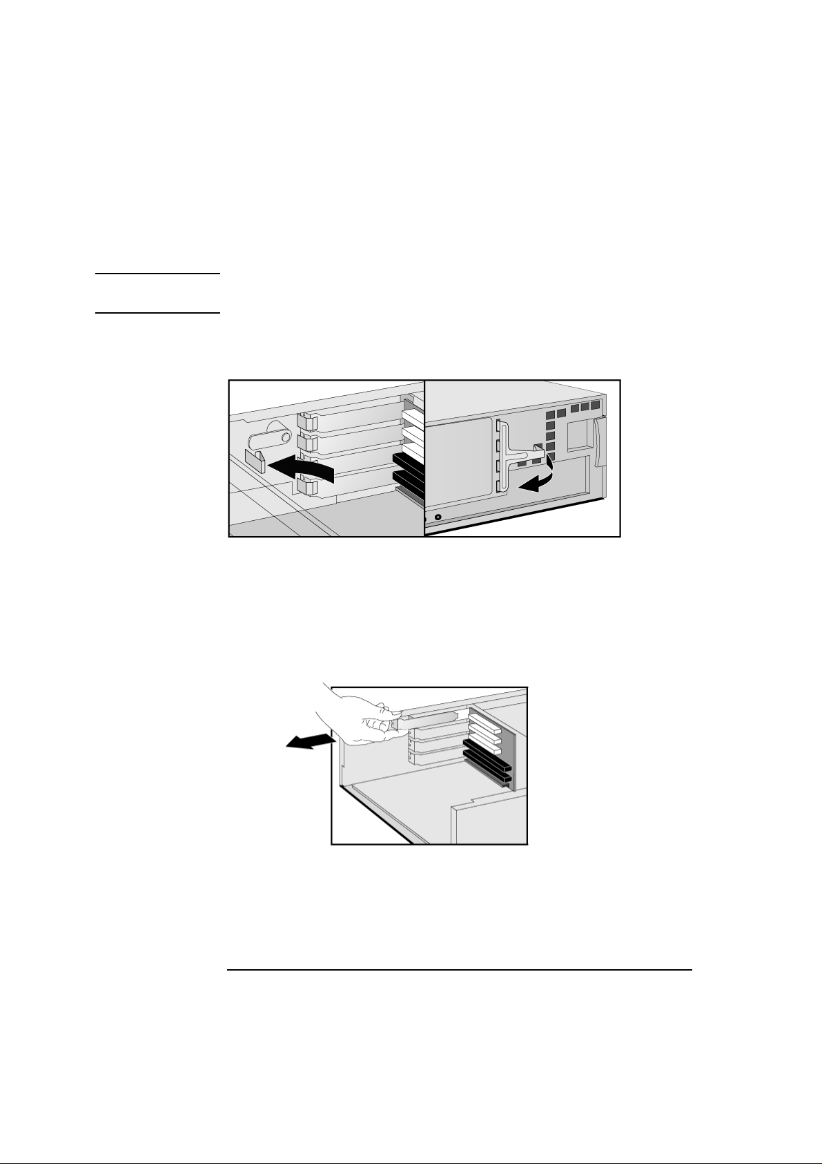
Installing an Accessory Board
NOTE Use only XT format ISA accessory boards (width less than 10.4 cm or
4.09 inches).
Remove the computer’s cover (described in this chapter).
1
Remove the retaining bracket.
2
If the selected accessory board slot is located behind the processor,
3
you may need to slide out the system board to allow access (refer to
see “Replacing the System Board” on page 72 for information on how
to do this).
Remove the slot cover.
4
66
Page 25

2 How to Install and Replace Components In Your Desktop PC
Installing Accessory Boards
5 Aligning the board carefully, slide it into position and press it firmly
into the slot.
6 If you slid out the system board to allow access to a lower slot,
replace it.
7 Replace the retaining bracket.
67
Page 26

2 How to Install and Replace Components In Your Desktop PC
Installing Accessory Boards
8 The accessory board may need a special connection, such as:
WOL (Wake on LAN) connector to the Network board.
•
CD-ROM drive to the sound board (if you no longer want to use
•
the integrated audio).
Integrated Audio Connector
If you install an add-on sound
board, remove the cable in this
connector and insert it into the
sound board’s connector.
WOL Connector
For more information, refer to the documentation that came with
the accessory board. The necessary cables are usually provided with
the accessory board.
NOTE If you install a network board and connect it to the WOL connector, you
must enable the
Integrated Network fields in the Power menu of the PC’s Setup
Suspend Wake-Up/Integrated Network
and/or
program. This only applies if the network board supports these modes.
To enter the Setup program, press F2 during startup.
If you install an add-on sound board (and you no longer want to use the
integrated audio), you must set the
Integrated Audio Interface in
the Advanced menu of the Setup program to Disabled.
9 Replace the cover (described in this chapter).
68
Page 27

2 How to Install and Replace Components In Your Desktop PC
Installing Accessory Boards
Configuring Accessory Boards with Plug and Play
Plug and Play is an industry standard for automatically configuring
your PC's hardware resources and the accessory boards installed in it.
Your PC has configurable support for Plug and Play in the BIOS.
All PCI accessory boards are Plug and Play , although not all ISA boards
are. Check the accessory board’s documentation if you are unsure.
When you start your PC after installing an accessory board, the Plug
and Play BIOS automatically detects which hardware resources (IRQs,
DMAs, memory ranges, and I/O addresses) are used by PC components
(such as the keyboard, the communications ports, network adapters,
and accessory boards).
Windows 95 and
Windows 98
Operating sy stems that support Plug and Play, such as Windows 95 and
Windows 98, will automatically detect a newly installed Plug and Play
accessory board and install the driver for this device, if the driver is
available.
Windows NT 4.0
For operating systems that do not support Plug and Play, such as
Windows NT 4.0, refer to the operating system documentation for
information about installing accessory boards.
In Windows NT 4.0, click the
Start button then click Help. You can
use the contents or index to find information about installing devices.
Windows NT 4.0 helps you through the installation of devices such as
modems and sound boards.
NOTE After installing a new device in Windows NT 4.0, you must re-install the
Microsoft Service Pack to update the operating system for your PC.
To do this, click the
NT Update.
Start button then select Programs – Windows
69
Page 28

2 How to Install and Replace Components In Your Desktop PC
Installing Accessory Boards
Configuring non-Plug and Play ISA Accessory Boards
If you install an ISA accessory board that is not Plug and Play, you will
need to configure the board before your PC can use it. For instructions
about configuring the board, refer to the documentation that came
with the board.
For guidelines on available IRQs and I/O addresses in your PC, refer to
page 119. Some operating systems, such as Windows 95, can display
the IRQs and I/O addresses currently used by your PC. Refer to the
operating system documentation for more information.
Refer to the documentation supplied with the operating system for
details on your operating system’s capabilities and restrictions
concerning non-Plug and Play accessory boards.
Resetting the PC’s
Configuration Data
If your PC is having difficulty recognizing the ISA board, try resetting
the PC’s data configuration. This will clear any old configuration data
that is no longer used. T o do this, enter the PC’ s Setup program, set the
Reset Configuration Data
To enter the Setup program, press
parameter to Yes, and restart the PC.
F2 during startup.
70
Page 29

2 How to Install and Replace Components In Your Desktop PC
Replacing the Processor
Remove the computer’s cover (described in this chapter).
1
Remove the old processor.
2
Replacing the Processor
Install the new processor and clip it into place.
3
If the new processor is a different speed, ensure that the system
4
board switches are correctly set for your processor speed. (The
correct switch settings are indicated on the system board.)
Replace the cover (described in this chapter).
5
Ensure that the latest version of BIOS is installed on your PC. To
6
learn which version of BIOS is currently installed on your PC, press
ESC during startup. To get the latest BIOS version for your PC,
connect to the web site
www.hp.com/go/vectrasupport.
71
Page 30

2 How to Install and Replace Components In Your Desktop PC
Replacing the System Board
Replacing the System Board
Remove the computer’s cover (described in this chapter).
1
Remove the lower bracket.
2
Remove the main memory and processor from the old system board
3
(described in this chapter).
Remove the old system board.
4
72
Page 31
2 How to Install and Replace Components In Your Desktop PC
Replacing the System Board
5 First ensure the lever is open, then carefully slide in the new system
board, aligning the rails and the rear connector bracket correctly.
6 Pushing on the lever and on the system board edge, slide the system
board firmly into place. Ensure the connectors are well aligned and
fully engaged.
7 Replace the main memory and processor in the new system board
(described in this chapter).
8 Replace the lower bracket.
9 Replace the cover (described in this chapter).
73
Page 32

2 How to Install and Replace Components In Your Desktop PC
Replacing the Power Supply
Replacing the Power Supply
WARNING
Hard drive(s)
To avoid electric shock, do not open the power supply. There are no userserviceable parts inside.
Remove the computer’s cover (described in this chapter).
1
Remove all internal power supply connectors.
2
DVD/CD-ROM
drive(s)
Remove the hard drive tray (described in this chapter).
3
Remove the four screws securing the power supply.
4
Floppy drive
Main power
(
located on backplane near
power supply)
Slide the old power supply forward and remove it.
5
74
Page 33

2 How to Install and Replace Components In Your Desktop PC
Replacing the Power Supply
6 Insert the new power supply (lining up the metal catches).
7 Replace the four screws to secure the power supply.
8 Re-install the hard drive tray (described in this chapter).
9 Reconnect all internal power supply connectors.
10 Replace the cover (described in this chapter).
11 Select the correct voltage setting for your country.
75
Page 34

2 How to Install and Replace Components In Your Desktop PC
Changing the Battery
Changing the Battery
WARNING
There is a danger of explosion if the battery is incorrectly installed. For
your safety, never attempt to recharge, disassemble, or burn the old
battery. Replace the battery only with the same or equivalent type
recommended by the manufacturer. The battery in this PC is a lithium
battery which does not contain heavy metals, nevertheless, in order to
protect the environment, do not dispose of batteries in household
waste. Please return used batteries to the shop from which you bought
them, or to the dealer from which you purchased your PC, or to HP, so
that they can either be recycled or disposed of in an environmentally
sound way. Returned used batteries will be accepted free of charge.
You should order replacement battery HP 1420-0356 from your local
Sales and Service office, or a “CR2032 type” battery, which is available
from most local stores.
After removing the computer’s cover:
Remove the old battery by pressing the retaining clip with a
1
screwdriver and lifting the battery clear of the battery holder.
Place the new battery in the battery holder, with the “
2
“ sign on top,
+
and ensure it is properly seated.
After installing a replacement battery, replace the computer’s cover
and run the Setup program to reconfigure the computer. You enter
Setup by pressing
76
F2
at startup.
Page 35

2 How to Install and Replace Components In Your Desktop PC
Installing a Security Cable
Installing a Security Cable
You can secure the PC to your desk, or any other fixed object, using a
Kensington
TM
security cable. Using a security cable will also lock the
cover onto the PC.
The PC has a slot at the rear for securing the cable.
Insert the lock into the slot located at the rear of the PC.
1
Turn the key to lock the cable to the PC.
2
Remove the key and store it in a safe place.
3
NOTE The Kensington
ordered from HP. Contact your reseller for more information.
TM
security cable is not an HP accessory. It cannot be
77
Page 36

2 How to Install and Replace Components In Your Desktop PC
Installing a Security Cable
78
 Loading...