

HP Vectra XM5 4, Vectra XM 5/xx 4 User Manual

HP Vectra XM 5/xx
Series 4 PCs
User's Guide

Table of Contents
WELCOME TO YOUR HP VECTRA PC 7
1 SETTING UP AND USING YOUR PC 9
UNPACKING YOUR PC 9
CONNECTING THE MOUSE, KEYBOARD, AND DISPLAY 11
CONNECTING TO A NETWORK 12
CONNECTING A PRINTER 13
CONNECTING THE POWER CORDS 14
YOUR PC’S HARDWARE CONTROL PANEL 15
THE HP VECTRA KEYBOARD 16
STARTING AND STOPPING YOUR PC 17
STARTING THE PC FOR THE FIRST TIME 18
2 HOW TO INSTALL ACCESSORIES IN YOUR PC 20
STOPPING YOUR PC 20
HP USER TOOLS 20
HP SUMMARY SCREEN 20
SUPPORTED HP ACCESSORIES 20
REMOVING THE COVER 22
REPLACING THE COVER AFTER INSTALLING ACCESSORIES 24
MOVING AND REPLACING THE POWER SUPPLY 24
REPLACING THE POWER SUPPLY AFTER INSTALLING
ACCESSORIES 26
INSTALLING MEMORY 26
INSTALLING AN OPTIONAL CACHE MEMORY MODULE 28
INSTALLING A VIDEO MEMORY UPGRADE 29
INSTALLING ACCESSORY BOARDS 30
CONFIGURING ACCESSORY BOARDS WITH PLUG AND PLAY 30
CONFIGURING NON-PLUG AND PLAY ISA ACCESSORY BOARDS 30
INSTALLING THE BOARD 31
INSTALLING A BNC COAX ADAPTER 34
INSTALLING MASS STORAGE DEVICES 36
CONFIGURING A DEVICE AFTER INSTALLATION 37
CONNECTING IDE DEVICES 37
INSTALLING A FLEXIBLE DISK DRIVE OR A CD-ROM DRIVE IN THE
MIDDLE SHELF 39
INSTALLING AN IDE HARD DISK DRIVE IN THE REAR SHELF 41
INSTALLING AN IDE HARD DISK DRIVE IN THE BOTTOM SHELF 43
INSTALLING A TAPE DRIVE IN THE BOTTOM SHELF 46
INSTALLING AN UPGRADE PROCESSOR 48
INSTALLING THE SECURITY BRACKET 50
CONFIGURING A SCSI HARD DISK DRIVE 50

3 THE HP SETUP PROGRAM 51
THE HP SUMMARY SCREEN AND SETUP PROGRAM 51
HP SUMMARY SCREEN 51
HP SETUP PROGRAM 52
USING THE
UNDERSTANDING THE SETUP PROGRAM 54
SETTING PASSWORDS 64
CONFIGURING YOUR NETWORK CONNECTION 65
SETUP
MAIN MENU ITEMS 55
CONFIGURATION MENU ITEMS 56
SECURITY MENU ITEMS 59
POWER MENU ITEMS 62
EXIT MENU ITEMS 64
SETTING AN ADMINISTRATOR PASSWORD 64
SETTING A USER PASSWORD 65
CONTROLLING THE NETWORK SECURITY FEATURES 66
CONTROLLING THE REMOTE PROGRAM LOAD 66
CONFIGURING THE PCI INTEGRATED ETHERNET INTERFACE 67
SAVING YOUR CHANGES AND LEAVING SETUP 68
PROGRAM 53
4 TROUBLESHOOTING YOUR PC 69
SOLVING PROBLEMS 69
HP SUMMARY SCREEN 69
IF YOUR PC DOES NOT START PROPERLY 69
DISPLAY IS BLANK AND THERE ARE NO ERROR MESSAGES 69
IF YOU ARE UNABLE TO CHANGE ANY VALUES IN
IF A POST ERROR MESSAGE IS DISPLAYED 71
IF YOU CANNOT TURN OFF YOUR PC 72
IF YOUR PC HAS A HARDWARE PROBLEM 72
DISPLAY DOES NOT WORK PROPERLY 72
IF YOUR KEYBOARD DOES NOT WORK 74
IF YOUR MOUSE DOES NOT WORK 74
IF YOUR PRINTER DOES NOT WORK 74
IF THE FLEXIBLE DISK DRIVE DOES NOT WORK 75
IF THE HARD DISK DOES NOT WORK 75
IF THE CD-ROM DRIVE DOES NOT WORK 76
IF AN ACCESSORY BOARD DOES NOT WORK 76
IF YOUR PC HAS A SOFTWARE PROBLEM 77
IF YOUR APPLICATION SOFTWARE DOES NOT WORK 77
IF THE DATE AND TIME ARE INCORRECT 78
IF YOU HAVE A NETWORK PROBLEM 78
CHANGING THE BATTERY 78
IF THE SCSI HARD DISK STOPS WORKING 80
IF YOU LOSE THE KEY 80
SETUP
70

5 TECHNICAL INFORMATION 81
SPECIFICATIONS 81
CHARACTERISTICS 82
POWER CONSUMPTION 82
IRQS, DMAS, AND I/O ADDRESSES USED BY YOUR PC 83
AVAILABLE VIDEO RESOLUTIONS 84
THE PC'S MEMORY MAP 85
THE PC'S REAR CONNECTORS 86
SYSTEM BOARD CONNECTORS AND SWITCHES 87
RECYCLING YOUR PC 8 8
6 HEWLETT PACKARD SUPPORT AND INFORMATION SERVICES
89
INTRODUCTION 89
YOUR HP AUTHORIZED RESELLER 89
HP SUPPORTPACK 90
HP SUPPORT ASSISTANT CD-ROM 90
HEWLETT-PACKARD INFORMATION SERVICES 90
HP FORUM ON COMPUSERVE 90
HP FORUM ON AMERICA ONLINE 91
HP BBS LIBRARY 91
INTERNET—FTP LIBRARY SERVICE 92
ACCESS HP WORLD WIDE WEB SITE 92
HP FAXBACK ON DEMAND—HP FIRST 92
HP AUDIO TIPS (USA ONLY) HP AUTOMATED SUPPORT DIRECTORY 92
ORDERING DRIVERS AND BIOS ON DISKETTE{XE "DRIVERS"}{XE
"BIOS"} 93
HP SUPPORT SERVICES 93
HEWLETT-PACKARD TELEPHONE SUPPORT 94
LIFELINE TELEPHONE SUPPORT 95
HP NETWORK PHONE-IN SUPPORT SERVICE (NPS) 95
SUMMARY 96
HEWLETT-PACKARD MARKETING HEADQUARTERS 97
HP WORLD WIDE WEB SERVER 97
HP ANONYMOUS FTP SERVER 97
EUROPEAN CUSTOMER SUPPORT CENTER 97
HP WORLD WIDE WEB SERVER 98
HP ANONYMOUS FTP SERVER 98
EUROPEAN CUSTOMER SUPPORT CENTER 98
GLOSSARY 99

REGULATORY INFORMATION AND WARRANTY 102
REGULATORY INFORMATION 102
FCC (FOR USA ONLY) 102
HP HARDWARE WARRANTY 104
HP SOFTWARE PRODUCT LICENSE AGREEMENT AND SOFTWARE &
PRODUCT LIMITED WARRANTY 1 06

WELCOME TO YOUR HP VECTRA PC
Your high-performance HP Vectra PC provides:
• a Pentium™ processor in a Zero Insertion Force (ZIF) socket
• an integrated level-two cache of 256 KB for high performance (optional on some models)
• a main memory of 8 MB or 16 MB, upgradeable to 128 MB
• an Ultra VGA PCI (Peripheral Component Interconnect) video controller with 1 MB of
video memory upgradeable to 2 MB
• an integrated Enhanced IDE (Integrated Drive Electronics) controller on the PCI bus
supporting Fast IDE and Standard IDE
• four free slots for accessory boards:
• one 32-bit PCI (Peripheral Component Interconnect) slot
• one 16-bit ISA (Industry Standard Architecture) slot
• one 16-bit ISA short slot (16 cm/6.3-inch maximum length)
• one combination ISA or PCI slot
• BIOS stored in Flash ROM
• BIOS support for ISA “Plug and Play”
• pre-installed operating system software (on some models).
• DMI compliant
• designed for Windows
• Vectra Ergonomic Power Solution—Windows 95 soft power-down using the mouse, and
keyboard power-on.
• Energy Star compliant power management.
The PC range described in this manual has a power saving capability that complies with
the Environment Protection Agency’s 30 watt maximum power consumption in “sleep
mode”, except those PCs to which you add certain extra accessories, such as a CDROM. These PCs also have energy saving capabilities, but use slightly more than the
maximum 30 watt limit in power saving mode, required for the Energy Star label
approval.
® 95
1 SETTING UP AND USING YOUR PC
Typical Display
This chapter leads you through the first time installation of your HP Vectra PC and explains
how to use it.
UNPACKING YOUR PC
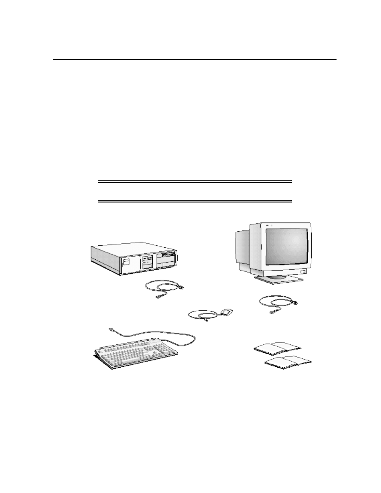
1 When you receive your PC, unpack all the components:
• the computer and power cord
• the display and its cables
• the keyboard and mouse
• the manuals.
On some models, the operating system software, drivers, and HP User Tools are preloaded on
the hard disk.
WARNING: If you have any doubt that you can lift the PC or
display safely, do not try to move it without help.
Computer
Computer Power Cord
Keyboard
Mouse
Display Power Cord
Manuals
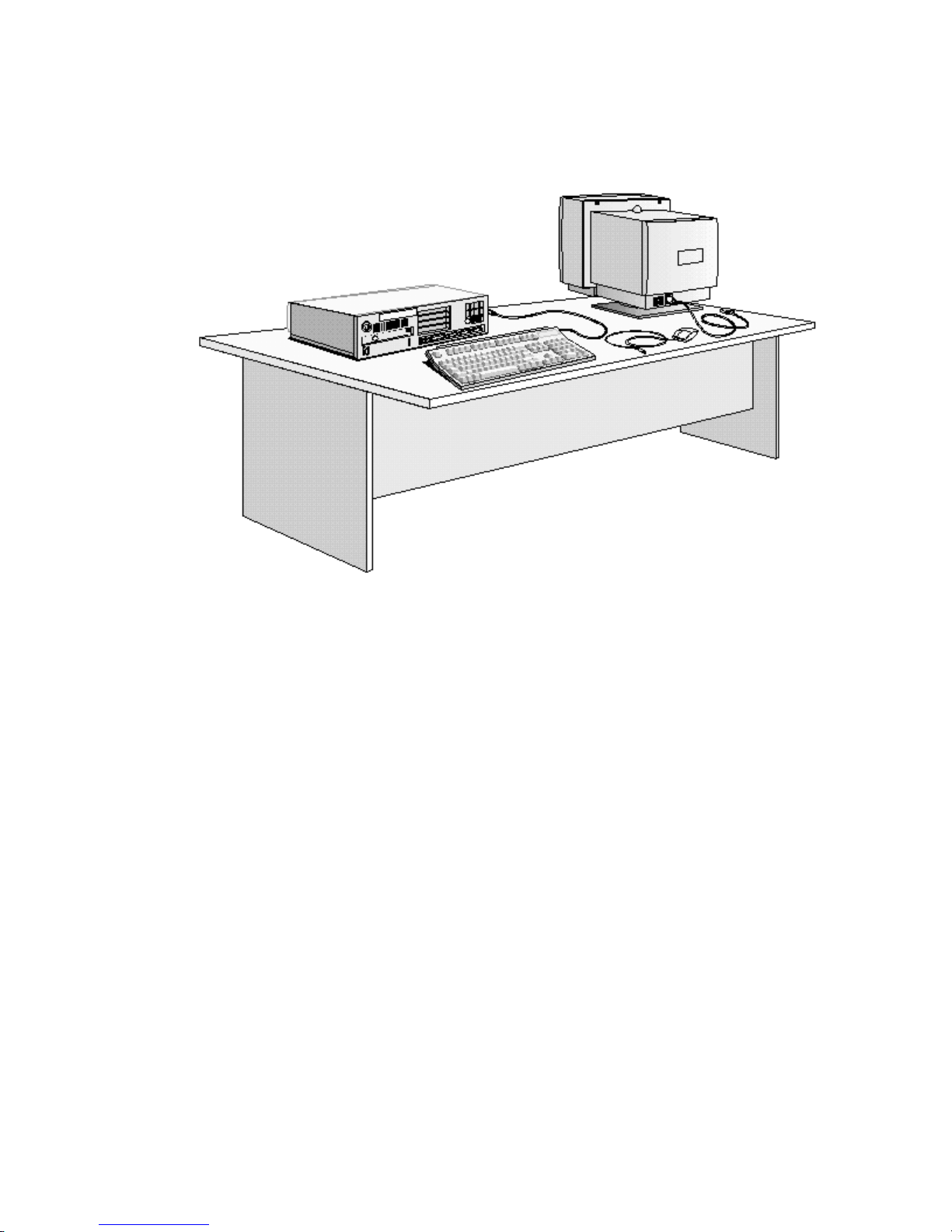
2 Place the PC on a sturdy desk near to easily accessible power outlets, with enough space for
the keyboard, mouse, and any other accessories.
3 Position the PC so that its rear connectors are easily accessible.
4 Place the display on top of the computer. If you have a large display, place it next to the
computer. Refer to the display’s manual for information about the display.
Installation Tools
No tools are required to set up your PC. However, if you plan to install a disk drive or an
accessory board in your PC, you will need a flat-blade screwdriver. For further information
about installing accessories, refer to chapter 3, “
How to Install Accessories In Your PC
”.
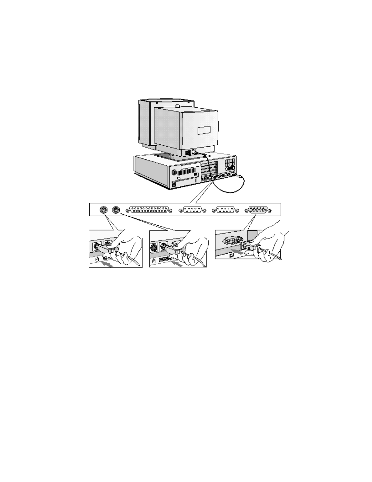
CONNECTING THE MOUSE, KEYBOARD, AND DISPLAY
1 Connect the mouse, keyboard, and display to the back of the computer.
are shaped to go in one way only
2 Tighten the display cable attachment screws.
.
The connectors
Mouse Keyboard Display
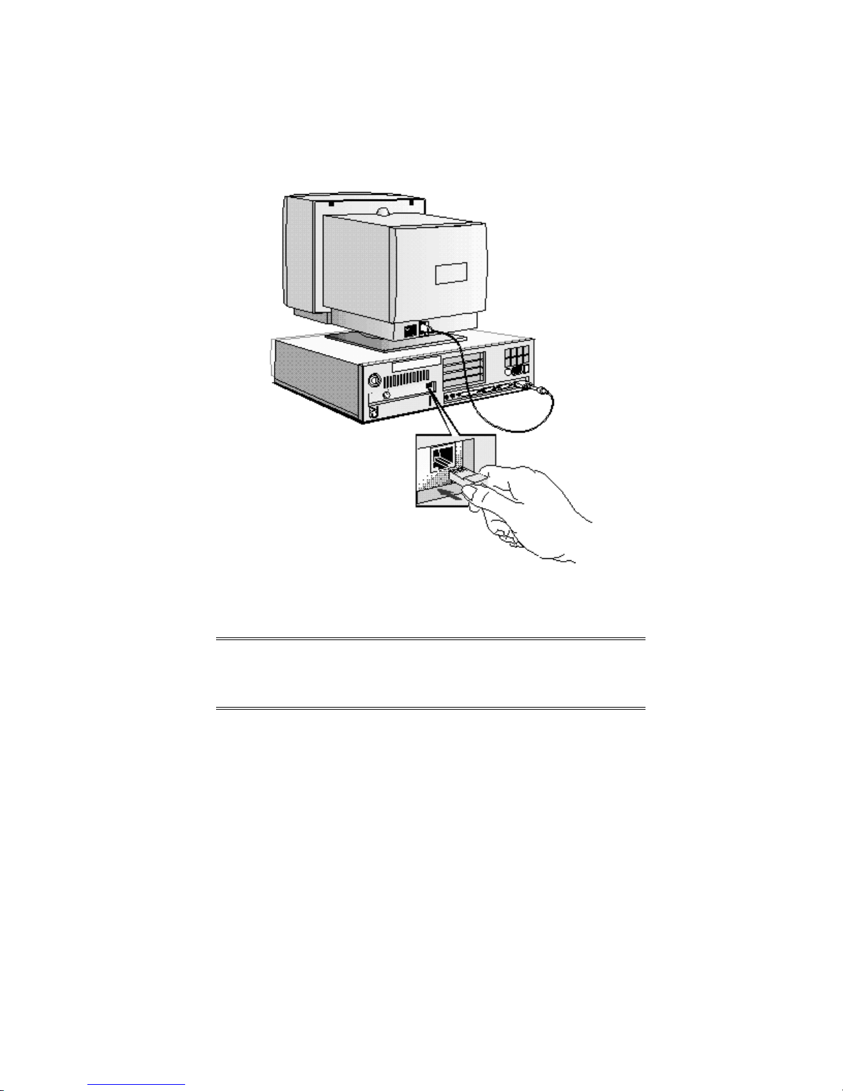
CONNECTING TO A NETWORK
Let your Network Administrator know you are connecting your PC to the network. Connect the
network cable to the RJ-45 UTP (Unshielded Twisted Pair) LAN connector.
To configure your network connection, refer to "Configuring Your Network Connection"
(chapter 3)
NOTE If you need a BNC Coax connector to connect to the
network, you can install an optional BNC coax
adapter (order HP D3979A). Refer to "Installing a
BNC Coax Adapter" (chapter 2).
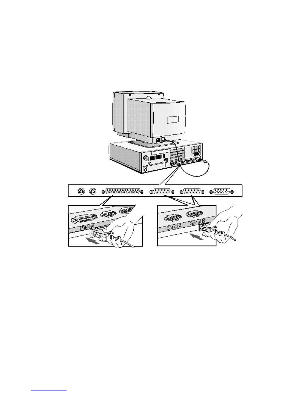
CONNECTING A PRINTER
Connect the printer cable to the back of the computer and tighten the attachment screws. Use
the connector labeled:
• Parallel (25-pin parallel connector) for a parallel device
• Serial A (9-pin serial connector) for a serial device
• Serial B (9-pin serial connector) for a second serial device.
Parallel Connector Serial Connector
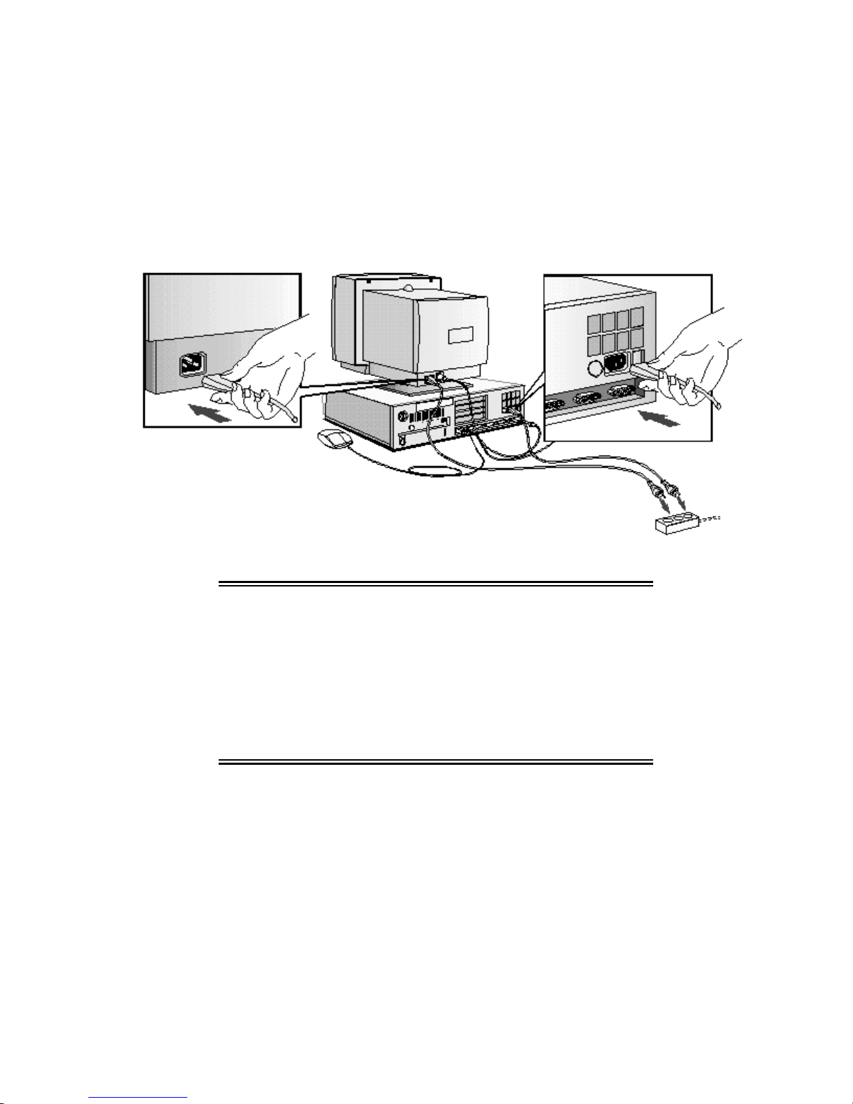
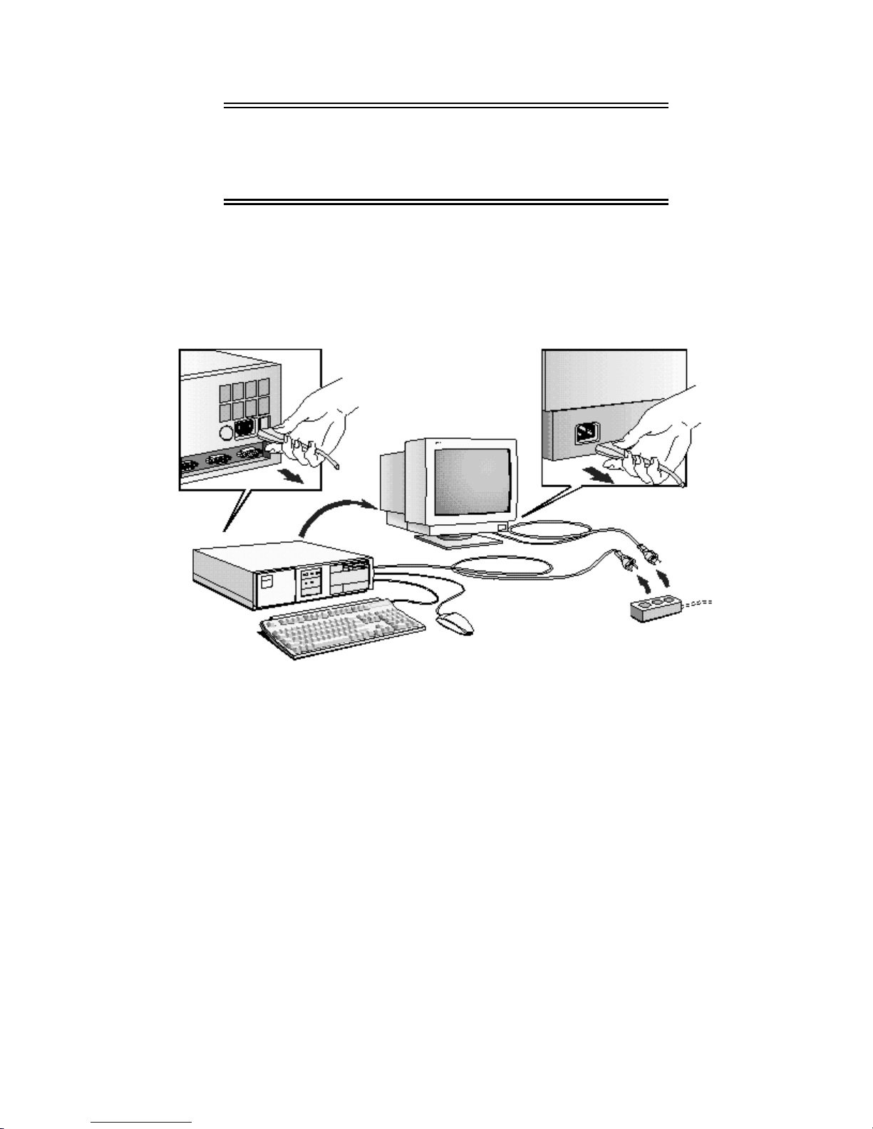
CONNECTING THE POWER CORDS
1 If fitted, remove the label covering the computer’s power connector.
2 Connect the power cords to the display and the computer. (
go in one way only
3 Connect the display’s power cord and the computer’s power cord to a grounded outlet.
Display Power Cord Computer Power Cord
.)
The connectors are shaped to
Grounded Outlet
WARNING: For your safety, always connect the equipment to
a grounded wall outlet. Always use a power cord
with a properly grounded plug, such as the one
provided with this equipment, or one in
compliance with your national regulations.
This PC is disconnected from the power by
removing the power cord from the power outlet.
This means the PC must be located close to a
power outlet that is easily accessible.
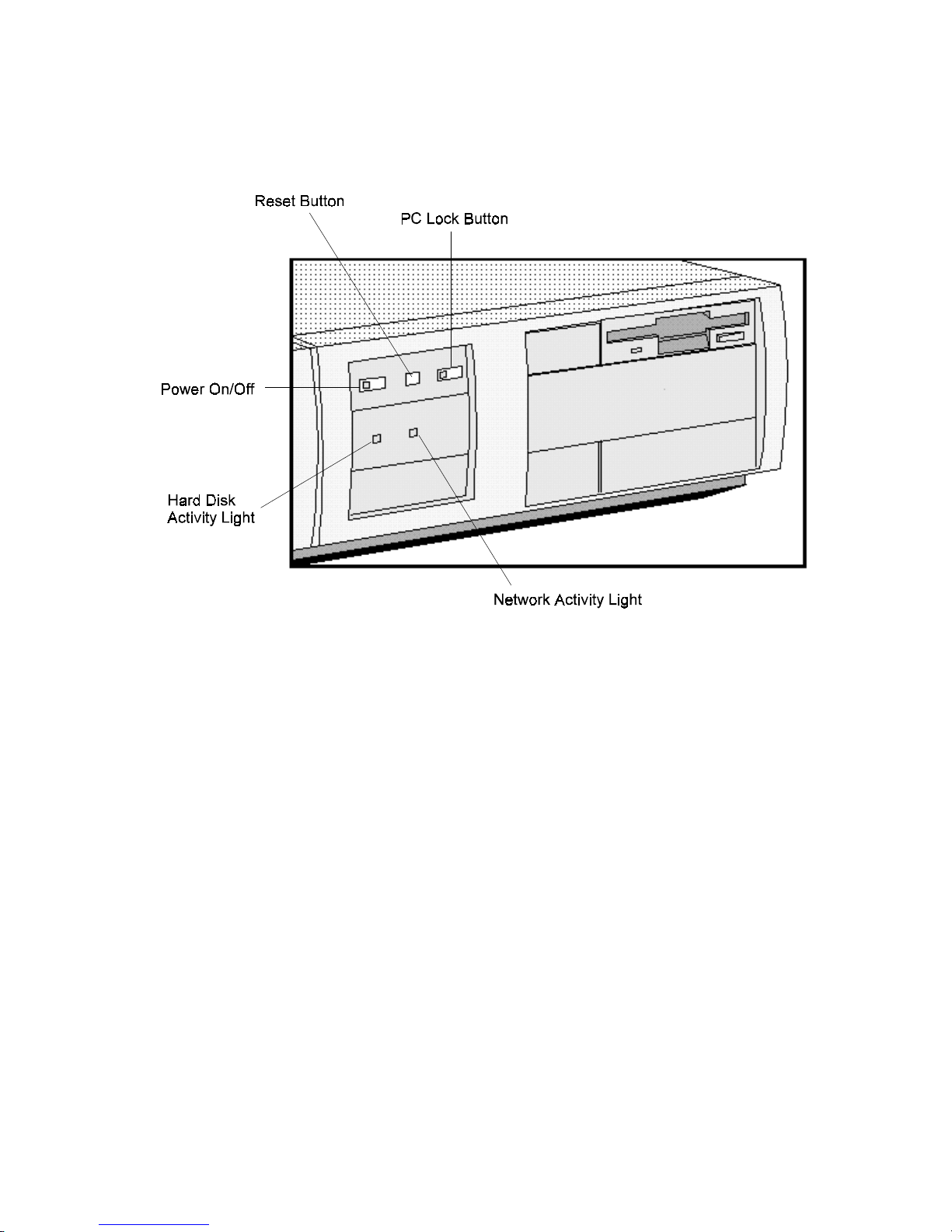
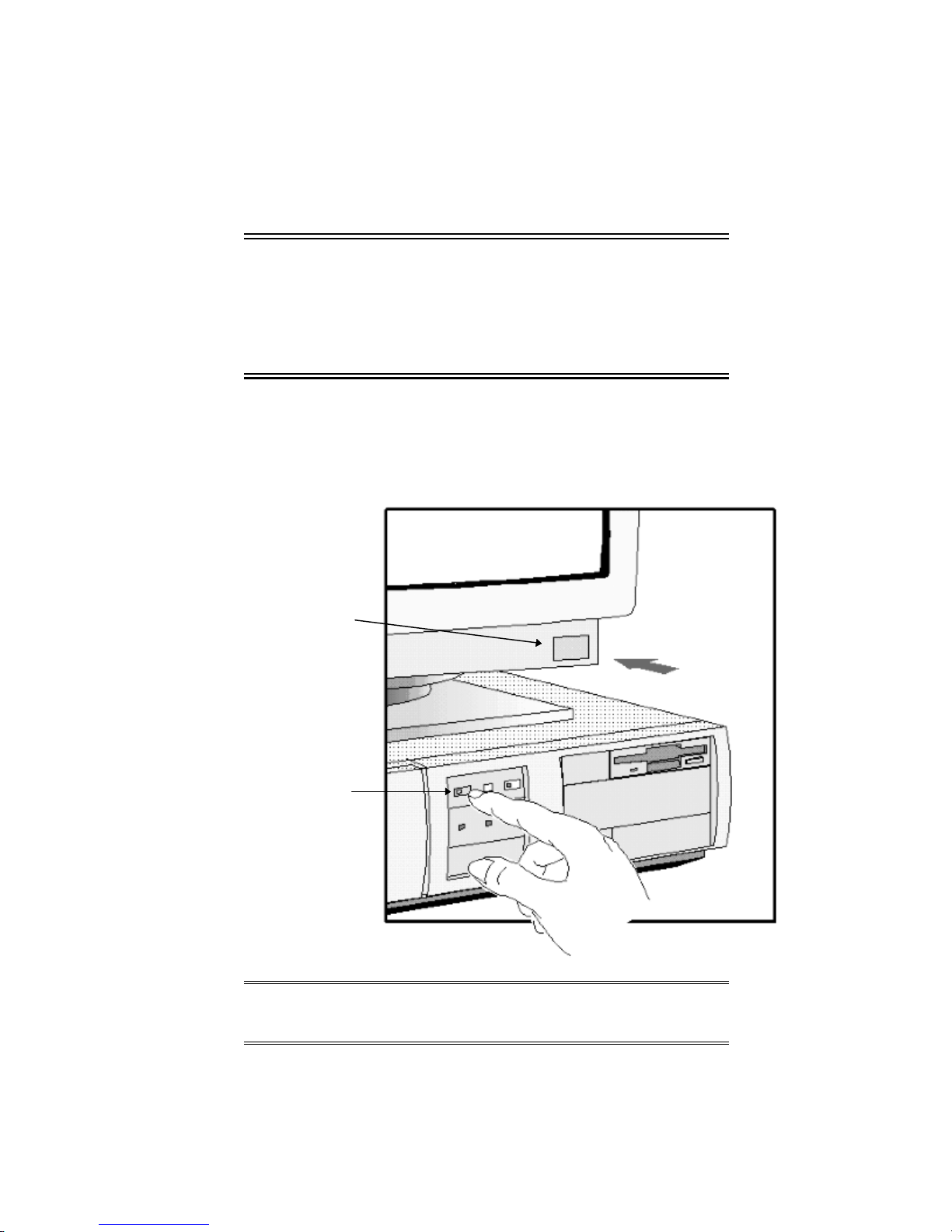
YOUR PC’S HARDWARE CONTROL PANEL
Your PC’s hardware control panel is on the front of your PC.
Power On/Off Button
Press this button to turn the power on or off to your PC.
Reset Button
Press this button to restart your PC without having to turn off your PC.
PC Lock Button
Press this button to lock your PC’c keyboard and mouse while you are away from the PC for a
short period of time. Your applications will remain active. You unlock the PC by entering a
password (see "Setting a User Password" in chapter 3).
Network Activity Light
This light glows/flickers when your PC is accessing the network.
Hard Disk Activity Light
This light glows/flickers when your hard disk drive is being accessed. The hard disk activity
light only works if you have an IDE hard disk drive, which comes with your Vectra PC. If you
replace this drive with a SCSI hard disk drive, this light will not work.
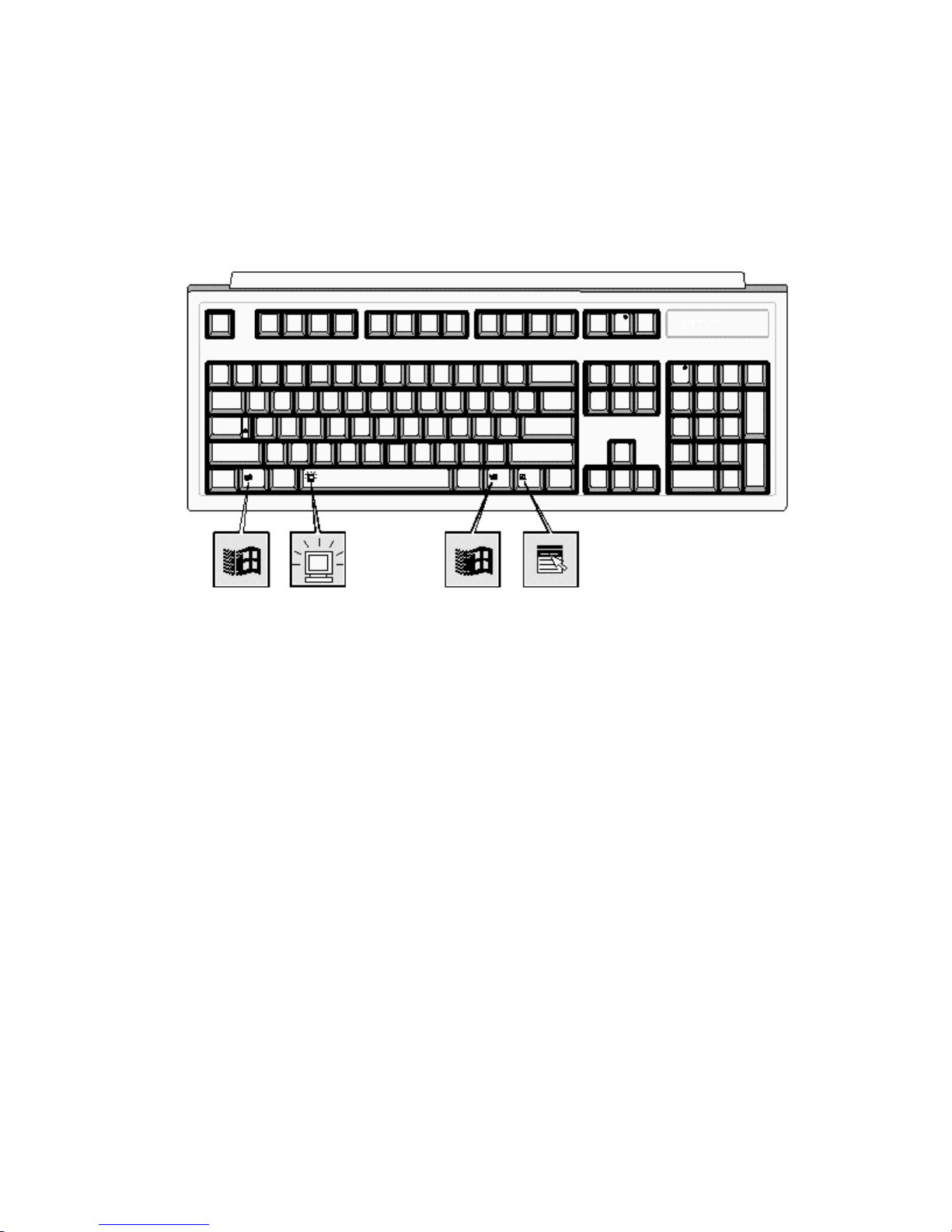
THE HP VECTRA KEYBOARD
The HP Vectra keyboard has three keys that give speedy access to Windows 95 functions.
These keys have icons indicating what these functions are.
The space bar also has an additional function, the “Power-On” function, which is not specific to
Windows 95.
The Windows Icon
You can display the Windows 95 Start menu by pressing either of the two Windows keys,
which are on either side of the space bar. Refer to Windows 95 documentation for further
information about Windows 95.
The Application Key
The Application key (specific to Windows 95) lets you access all the same functions as the right
mouse button. Use it to copy and move files, to access shortcut menus, and to get Help
information. The Application key can also be programmed by your software.
The Power-On Icon on the Space Bar
The Power-On function enables you to start your PC by pressing the space bar. This function is
not specific to Windows 95—it is available whatever your operating system. You can enable or
disable this function in the Setup program. The default is
disable this function with system board switch 9 (refer to "System Board Connectors and
Switches" in chapter 5).
enabled
. You can also enable or
STARTING AND STOPPING YOUR PC
Starting Your PC
NOTE If you are starting your PC for the first time, refer to
"Starting the PC for the First Time" in this chapter.
To stop your PC, refer to "Stopping Your PC" in this
chapter.
1 Before you start your PC, always switch on the display first.
2 Start your PC in one of these ways:
• press the power button on the front panel
• press the space bar.
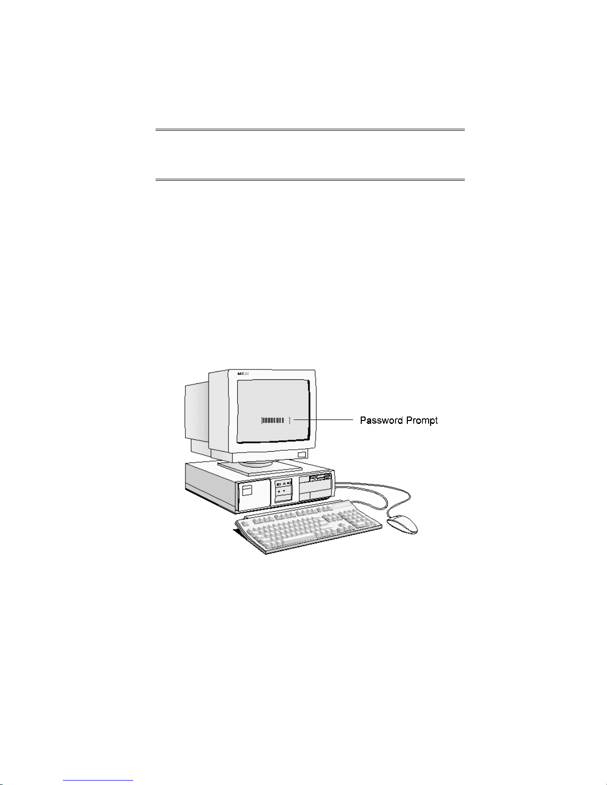
When you switch on the computer, the computer carries out the Power-On-Self-Test (POST)
while the Vectra logo is displayed. If you wish to view the POST details, press [ESC] to get the
HP Summary Screen. If there is an error in the POST, the error will automatically be displayed.
Setup
3 If you have set a password in the PC’s
the POST has completed. If the Password prompt is displayed, type your password and
press [ENTER] to be able to use the PC.
program, the password prompt displays after
STARTING THE PC FOR THE FIRST TIME
If your PC has preinstalled software, it is initialized the first time you start the PC. The software
initialization process takes approximately three minutes. This process sets up the software in
your language and sets up your software to use the hardware installed in your computer (you
can change the settings after the software has been initialized).
CAUTION: Depending on which model PC you have, you may
also be asked to select which operating system you
want to use, for example Windows 3.11 or Windows
95. Once you have confirmed your selection of the
operating system, you cannot change that selection.
The operating system that you have NOT chosen will
be deleted from the computer’s hard disk.
Initializing Your Software
To initialize your software:
1 Turn on the display first, and then the PC.
Switch on the Display
Then switch on the PC
NOTE Do NOT switch OFF the PC while the software is
being initialized—this could cause unexpected
results.
When the PC is switched on, the Vectra Logo is displayed. The PC performs a Power-On-SelfTest (POST). Press [ESC] if you want to view the POST details in the HP Summary Screen
(refer to "The HP Summary Screen and Setup Program").

If an error is detected during the Power-On-Self-Test, the PC will automatically display the
Setup
error. You may be prompted to press [F2] to start the
2 The software initialization routine starts. It displays the software license agreement, gives
you an opportunity to read Working in Comfort (ergonomic advice for computer users),
and then asks questions about the PC. For example:
• The name of the person who will use the PC and your company name. (If necessary,
the name of the user can be modified later.)
• The current date and time.
• The type of printer (for example, HP LaserJet 4M). This is shown on the front of the
printer. You also need to enter the connection used by the printer.
• The model number of your display. The display’s model number is shown on the cover
of the manual supplied with the display and on a label on the rear of the display.
• Depending on which model PC you have, you may also be asked to select which
operating system you want to use, Windows 3.11 or Windows 95. Once you have
confirmed your selection of the operating system, you cannot change that selection.
The operating system that you have NOT chosen will be deleted from the computer’s
hard disk
3 While the initialization program is running, you can complete the Warranty Registration
card that you will find inside the back of this manual.
program to correct the error.
When the initialization routine has finished, click on OK and the PC will restart.
After Your PC Has Restarted
• Set the keyboard to a comfortable position.
• Adjust the display screen’s brightness and contrast to suit your needs. If the picture does
not fill the screen or is not centered, adjust it using the controls on the display. Refer to the
display’s manual for details.
Creating Master Diskettes
It is very important that you create master diskettes for your preloaded software as soon as
possible. HP recommends that you use new diskettes. If you need to restore the preloaded
software on your PC, you can use these diskettes to do so.
For details on how to create these diskettes, refer to the documentation for your operating
system.

2 HOW TO INSTALL ACCESSORIES IN YOUR PC
This chapter explains how to install accessories, such as extra memory, accessory boards, and
additional disk drives, in your PC.
STOPPING YOUR PC
Stopping the PC when using Windows 3.11
To stop the PC, make sure that you have exited all programs and then exited Windows before
pressing the power button on the control panel.
Stopping the PC when using Windows 95
To stop or shut down the PC:
1 Click on Start.
2 Click on Shut Down.
3 Click on Shut down the computer.
You can return the PC to full power mode by pressing the space bar.
Other Operating Systems
For other operating systems refer to the operating system manual for details of how to exit the
operating system.
HP USER TOOLS
If your PC has preinstalled software, you will find HP User Tools on your system. These tools
help you to both configure your system and improve the functionality of your PC. They include
such items as configuring printers and setting video modes.
HP SUMMARY SCREEN
The HP Summary Screen provides information about your PC’s current configuration. To view
the Summary Screen, press [ESC] when the Vectra Logo appears during the Power-on-SelfTest (POST). Refer also to "The HP Summary Screen and Setup Program" in chapter 3.
SUPPORTED HP ACCESSORIES
This chapter describes how to install memory, mass storage devices, and accessory boards in
your PC.
Refer to "Hewlett Packard Support and Information Services" (chapter 6) for information about
how to obtain an up-to-date list of supported devices.
WARNING: For your safety, never remove the PC’s cover
without first removing the power cord from the
power outlet, and any connection to a
telecommunications network. Always replace the
cover on the PC before switching it on again.
REMOVING THE COVER
1 Switch off the display and the PC.
2 Disconnect the power cords from the power outlets, the PC, and the display. Disconnect
any connection to a telecommunications network. Then remove the display.
3 If necessary, unlock the cover using the key provided with the PC.
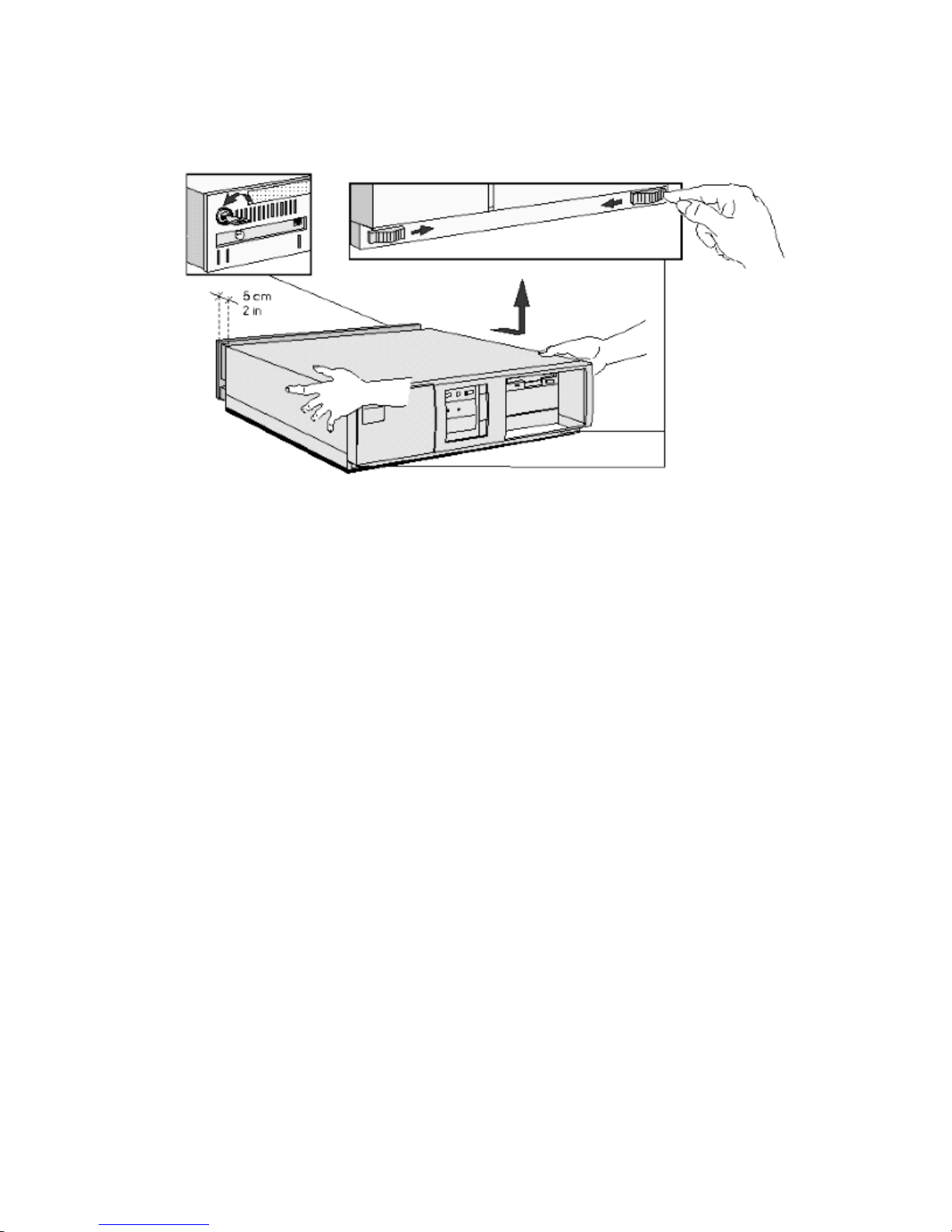
4 Slide the two tabs on the front of the computer inwards. Firmly slide the cover
forward 5 cm (2 inches), and lift it up and off the computer.
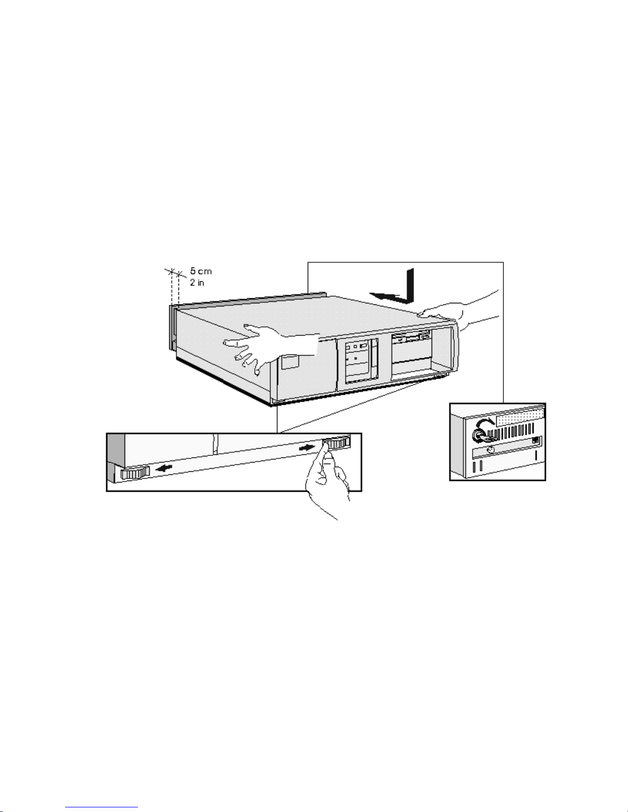
REPLACING THE COVER AFTER INSTALLING ACCESSORIES
1 Check that you have installed all your accessories.
2 Make sure that all internal cables are properly connected and safely routed so they will not
be entangled when you replace the cover.
3 Ensure the cover lock is unlocked and the tabs are inwards.
4 Lower the cover onto the computer, and firmly slide it into position.
5 Slide the two tabs on the front of the cover outwards.
6 If a keylock is fitted, lock the cover using the key.
7 Place the display on top of the computer. Reconnect all cables and power cords.
MOVING AND REPLACING THE POWER SUPPLY
You must move the power supply to access the sockets for the main memory, cache memory,
video memory, processor, battery, or accessory board slots.
1 Disconnect the computer’s power supply cord and any connection to a
telecommunications network.
2 Remove the computer’s cover.
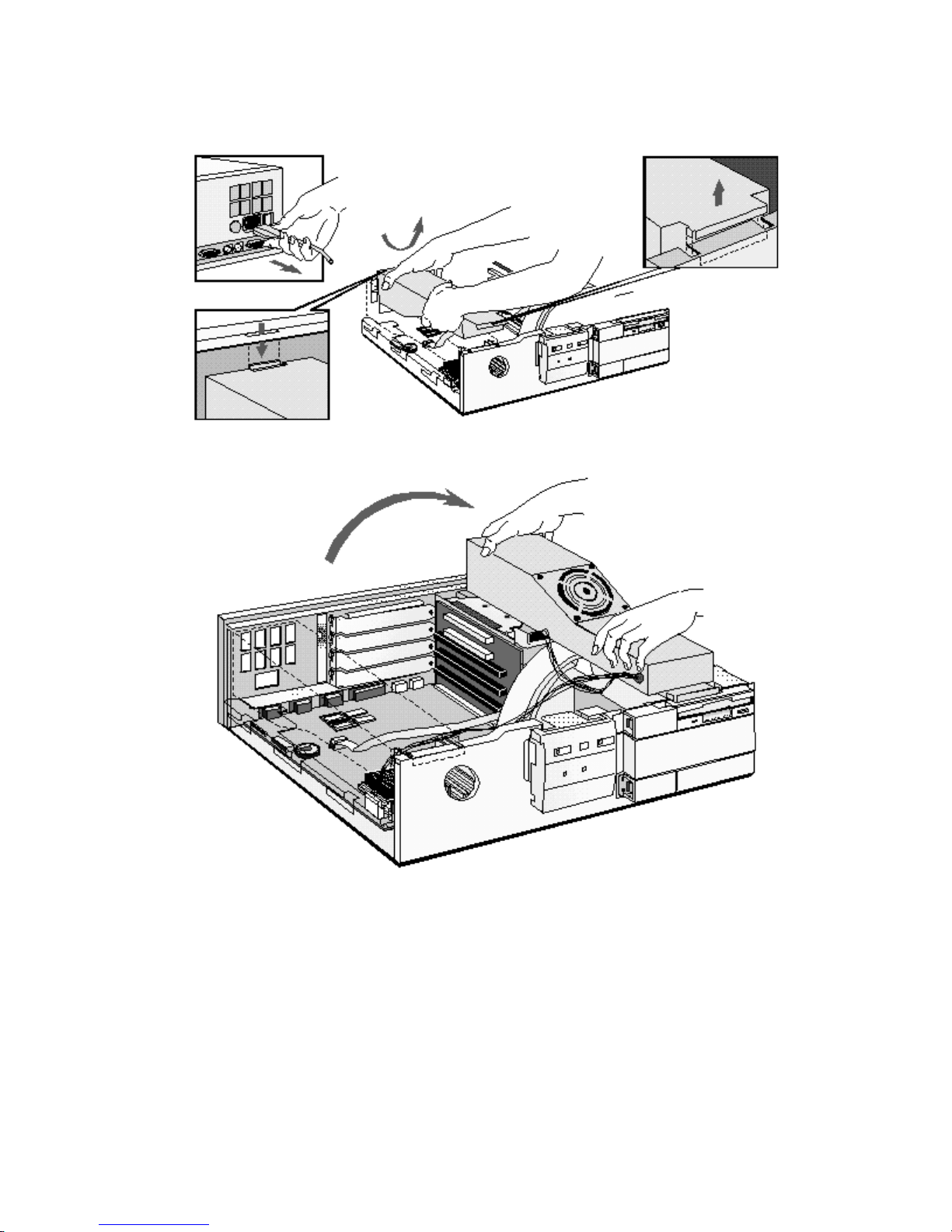
3 Lift the front of the power supply to disengage the hinge on the rear.
4 Lift the power supply clear and lay it upside down on the frame above the disk drives.
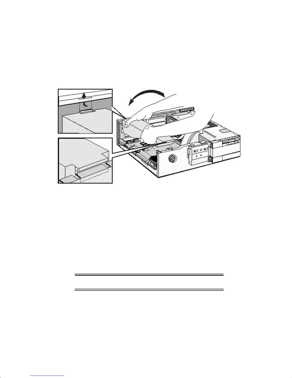
REPLACING THE POWER SUPPLY AFTER INSTALLING ACCESSORIES
1 Ensure that you have installed all your accessories in the PC.
2 Replace the power supply on the left-hand side of the PC, and ensure that the cables are
neatly routed around any accessory boards.
3 Raise the front of the power supply and engage the hinge on the rear.
4 Lower the front of the power supply into position so that it rests on the front panel.
INSTALLING MEMORY
Main Memory Modules
Your PC is supplied with main memory. If you need more main memory to run your application
software, you can install up to a total of 128 MB.
Main memory is available in modules of 4 MB, 8 MB, 16 MB, or 32 MB. You must install
identical modules in pairs in each bank.
Banks A and B will take 4 MB, 8 MB, 16 MB or 32 MB modules. Use only 4 MB and 16 MB
modules in bank C, as 8 MB and 32 MB modules are not fully detected in this bank.
CAUTION: Static electricity can damage electronic
components.
Turn all equipment OFF. Don’t let your clothes touch the accessory.
To equalize the static electricity, rest the accessory bag on top of the power supply while you
are removing the accessory from the bag. Handle the accessory as little as possible and with
care.
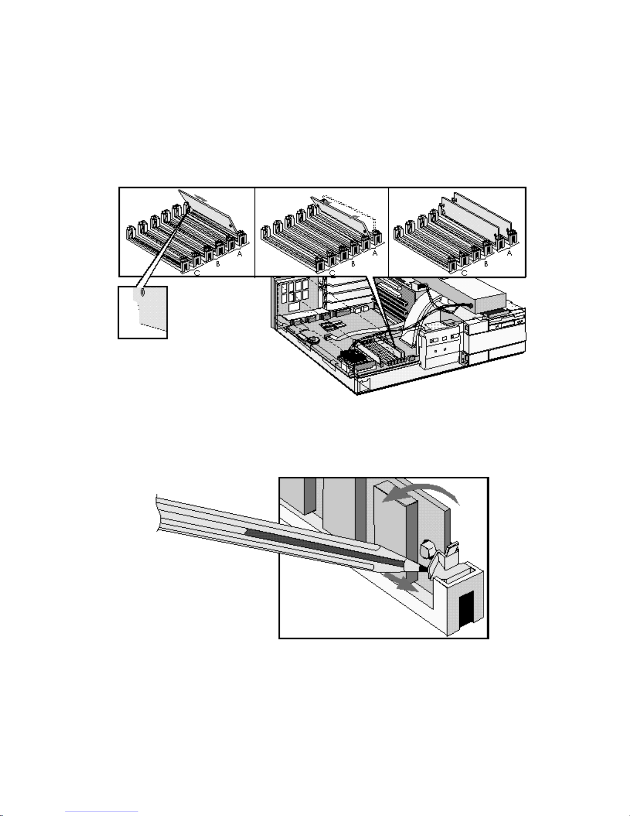
To install a main memory module:
1 Disconnect the computer’s power supply cord and any connection to a
telecommunications network.
2 Remove the computer’s cover and power supply.
3 Align the main memory module directly over the socket. Slide the memory module into the
slot at 45°. Firmly press the memory module completely into the connector.
4 Pivot the memory module to the vertical position and click into place.
5 Repeat this procedure for each memory module you are installing.If you need to remove a
main memory module:
Release the retaining clip and pull the module forward and out of the socket
6 Install any other accessories before replacing the cover and power supply. Reconnect all
cables and power cords.
7 Check the HP Summary Screen to verify the new configuration. Refer to "The HP
Summary Screen and Setup Program" in chapter 3.
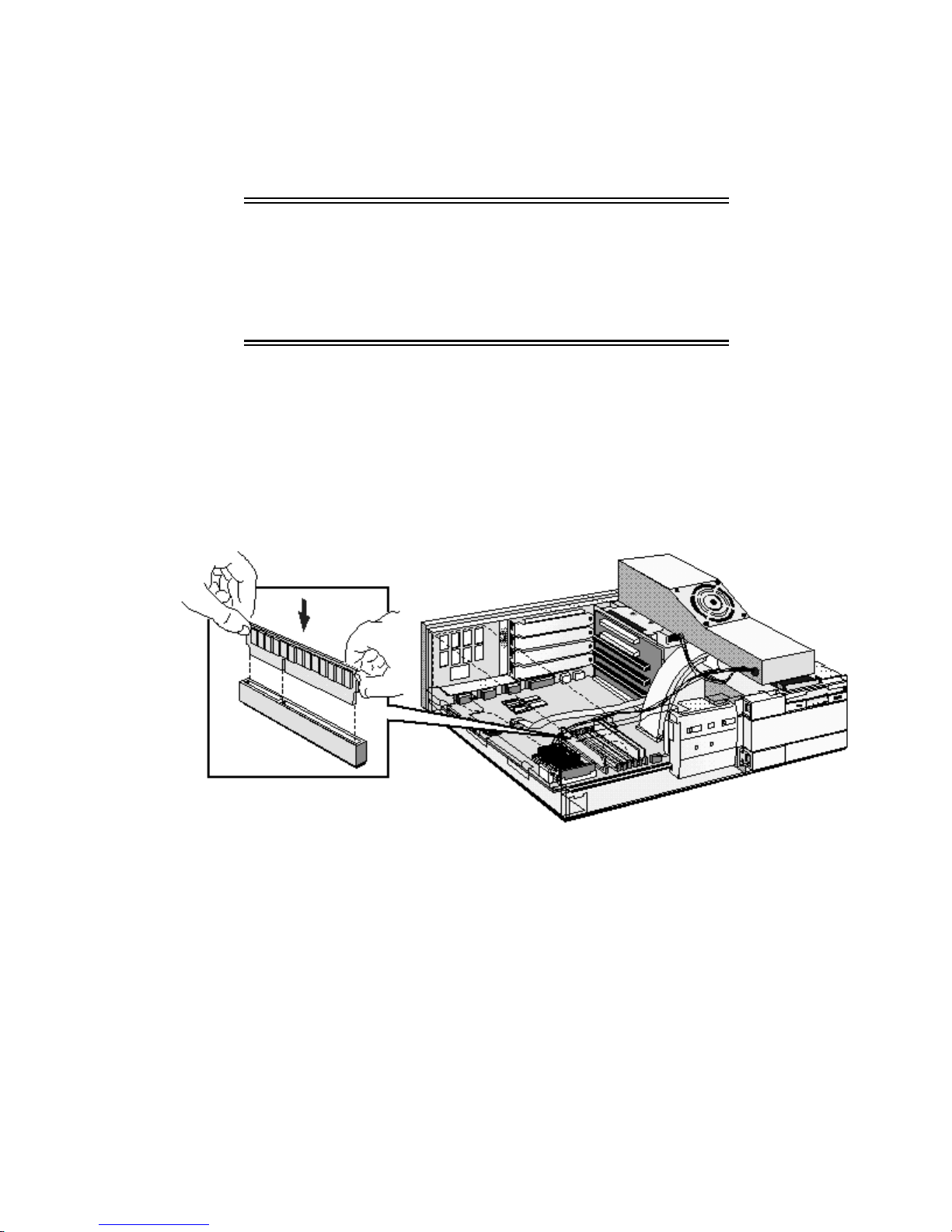
INSTALLING AN OPTIONAL CACHE MEMORY MODULE
If your PC does not come with one, you can install a 256 KB level 2 cache memory module.
Order HP D3659A.
CAUTION: Static electricity can damage electronic
components. Turn all equipment OFF. Don’t let
your clothes touch the accessory. To equalize
the static electricity, rest the accessory bag on
top of the power supply while you are removing
the accessory from the bag. Handle the
accessory as little as possible and with care.
To install a cache memory module:
1 Disconnect the computer’s power supply cord and any connection to a
telecommunications network.
2 Remove the computer’s cover and power supply.
3 Align the cache memory module directly over the socket. Firmly press the memory
module completely into the connector.
4 Install any other accessories before replacing the cover and power supply. Reconnect all
cables and power cords.
5 Check the HP Summary Screen to verify the new configuration. Refer to "The HP
Summary Screen and Setup Program" in chapter 3.
INSTALLING A VIDEO MEMORY UPGRADE
Your PC is supplied with 1 MB of video memory on the system board. If you want better
performance, higher resolutions or more colors, you can install a pair of video memory
modules to increase your available video memory to 2 MB. Detailed information about
available video resolutions is given in chapter 5, Technical Information.
CAUTION: Static electricity can damage electronic
components. Turn all equipment OFF. Don’t let
your clothes touch the accessory. To equalize
the static electricity, rest the accessory bag on
top of the power supply while you are removing
the accessory from the bag. Handle the
accessory as little as possible and with care.
Installing Video Memory Modules
To install a pair of video memory modules on the system board, follow this procedure:
1 Disconnect the power supply cord and any connection to a telecommunications network.
2 Remove the computer’s cover and power supply.
3 Align the video memory module directly over the socket taking care to align the dot on the
Firmly
module with the corner notch on the socket as illustrated in the diagram.
memory module
in pairs.
completely
into the connector. Video memory modules must be installed
press the
4 Install any other accessories before replacing the cover and power supply. Reconnect all
cables and power cords.

After Installing a Video Memory Upgrade
1 Switch on the PC.
2 Follow the instructions that come with your video memory upgrade or that are in your
operating system manual to configure the new video memory upgrade. On some models,
if supplied, you can select HP User Tools to configure the video memory upgrade.
3 You may be asked to insert a diskette containing an appropriate video driver in drive A.
For the latest version of a required driver, refer to the "HP BBS Library" in chapter 6.
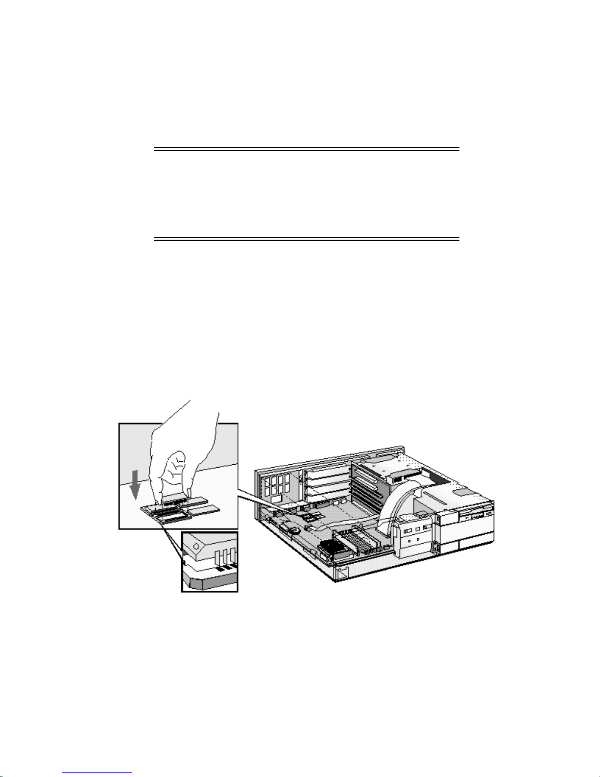
INSTALLING ACCESSORY BOARDS
The PC has four accessory board slots:
• Slot 1 (the top slot) can be used for a 32-bit PCI board
• Slot 2 can be used for either a 32-bit PCI or a full-length 16-bit ISA board
• Slot 3 can be used for full-length 16-bit ISA boards
• Slot 4 (the bottom slot) can be used for short-length 16-bit ISA boards (16 cm/6.3-inch
maximum length).
CONFIGURING ACCESSORY BOARDS WITH PLUG AND PLAY
Plug and Play is an industry standard for automatically configuring your PC's hardware
resources and the accessory boards installed in it. Your PC has configurable support for Plug
and Play in the BIOS.
NOTE All PCI accessory boards are Plug and Play,
although not all ISA boards are. Check the accessory
board’s documentation if you are unsure.
When you start your PC after installing an accessory board, the Plug and Play BIOS
automatically detects which hardware resources (IRQs, DMAs, memory ranges, and I/O
addresses) are used by the system-based components.
CONFIGURING NON-PLUG AND PLAY ISA ACCESSORY BOARDS
If you install an ISA accessory board that is not Plug and Play you will need to configure the
board before your PC can use it.
Windows 3.11
For Windows 3.11 you must run the ISA Configuration Utility (ICU) program to declare the
resources used by the board:
1 Double-click on the Plug and Play group icon in the Windows Program Manager.
2 Double-click on the ICU Notes icon for up-to-date information about the Plug and Play
support for your PC.
3 Double-click on the ICU User Guide icon for detailed information about using the ICU.

4 Double-click on the ICU icon to launch the ISA Configuration Utility and configure system
resources for the accessory board.
The ICU is preloaded with configuration details for many non-Plug and Play accessory
boards. If your accessory board is not listed by the ICU, you have two options:
a Some non-Plug and Play accessory boards are supplied with a configuration file,
which can be used by the ICU to determine which resources are required by the board.
Insert the disk containing the configuration file when prompted by the ICU.
b If you do not have a configuration file for your accessory board, you will need to enter
the configuration details manually when prompted by the ICU. Refer to the
documentation supplied with your accessory board for information on the resources
required by the board.
Windows 95
For Windows 95 you will need to run the Add New Hardware wizard to configure the
accessory board. The settings selected by Windows 95 may be different from those
recommended by the board’s manufacturer. Should this be the case, it might be necessary to
alter the board’s jumpers. Refer to the documentation supplied with Windows 95 for further
details.
Other Operating Systems
For other operating systems, refer to the documentation supplied with the operating system for
details on how to configure non-Plug and Play accessory boards.
INSTALLING THE BOARD
1 Disconnect the computer’s power supply cord and any connection to a
telecommunications network.
2 Remove the computer’s cover and power supply.
3 Find a free slot. Some boards may have preferred locations and special installation
instructions detailed in their manuals.
4 Unscrew and remove the slot cover. Store it in a safe place. If the slot cover is tight,
loosen the screws on the adjacent slots.
5 Hold the board horizontally by its “top” edge. Slide it into the board guide of the chosen
slot. Do not bend the board.
6 Align the board’s connector with the slot’s socket and firmly press into the socket. Ensure
the board’s connector engages completely with the socket and does not touch components
on other boards.
 Loading...