

HP Vectra VEC 7, Vectra VE C/xxx 7, Vectra VE C/xxx Supplementary Manual

Familiarization Guide
HP Vectra VE PC
HP Vectra VE MT PC
This guide is for experienced technicians who have
already completed the HP Vectra PC family training
course. It is a self-paced training guide designed to train
you to repair the PC. It contains information specific only
to the repair of these PCs. For information on the
installation of accessories, see the User’s Guide (supplied
with the PC) and the Upgrade and Maintenance Guide
(available from HP’s Support Web site at
http://www.hp.com/go/vectrasupport).
HP Vectra VE
C/xxx Series 7 PC

Notice
The information contained in this document is subject to change without notice.
Hewlett-Packard makes no warranty of any kind with regard to this
material, including, but not limited to, the implied warranties of
merchantability and fitness for a particular purpose.
Hewlett-Packard shall not be liable for errors contained herein or for incidental
or consequential damages in connection with the furnishing, performance, or use
of this material.
This document contains proprietary information that is protected by copyright.
All rights are reserved. No part of this document may be photocopied,
reproduced, or translated to another language without the prior written consent
of Hewlett-Packard Company.
Windows® is a U.S. registered trademark of the Microsoft Corporation.
Pentium® is a U.S. registered trademark of the Intel Corporation.
Hewlett-Packard France
Corporate Desktop Computing Division
38053 Grenoble Cedex 9
France
1998 Hewlett-Packard Company

Contents
Electrostatic Discharge Warning. . . . . . . . . . . . . . . . . . . . . . . . . . . . . . 1
Care of Hard Disk Drives . . . . . . . . . . . . . . . . . . . . . . . . . . . . . . . . . . . . 2
Vectra Product Hardware Comparison . . . . . . . . . . . . . . . . . . . . . . . . 3
Where to find information . . . . . . . . . . . . . . . . . . . . . . . . . . . . . . . . . . . . . 5
Desktop Models Package. . . . . . . . . . . . . . . . . . . . . . . . . . . . . . . . . . . . 6
Minitower Package . . . . . . . . . . . . . . . . . . . . . . . . . . . . . . . . . . . . . . . . . 7
System Board. . . . . . . . . . . . . . . . . . . . . . . . . . . . . . . . . . . . . . . . . . . . . . 8
System Board Switches. . . . . . . . . . . . . . . . . . . . . . . . . . . . . . . . . . . . . . . . 9
Removing and Replacing the Cover . . . . . . . . . . . . . . . . . . . . . . . . . . 10
Desktop Models. . . . . . . . . . . . . . . . . . . . . . . . . . . . . . . . . . . . . . . . . . . . . 10
Minitower Models . . . . . . . . . . . . . . . . . . . . . . . . . . . . . . . . . . . . . . . . . . . 11
Removing the Hard Disk and Floppy Disk Tray(s). . . . . . . . . . . . . . 13
Desktop Models. . . . . . . . . . . . . . . . . . . . . . . . . . . . . . . . . . . . . . . . . . . . . 13
Minitower Models . . . . . . . . . . . . . . . . . . . . . . . . . . . . . . . . . . . . . . . . . . . 13
Removing the Front Bezel . . . . . . . . . . . . . . . . . . . . . . . . . . . . . . . . . . 15
Desktop Models. . . . . . . . . . . . . . . . . . . . . . . . . . . . . . . . . . . . . . . . . . . . . 15
Minitower Models . . . . . . . . . . . . . . . . . . . . . . . . . . . . . . . . . . . . . . . . . . . 15
Removing the Power Supply Unit. . . . . . . . . . . . . . . . . . . . . . . . . . . . 16
Desktop Models. . . . . . . . . . . . . . . . . . . . . . . . . . . . . . . . . . . . . . . . . . . . . 16
Minitower Models . . . . . . . . . . . . . . . . . . . . . . . . . . . . . . . . . . . . . . . . . . . 17
Removing and Replacing the System Board . . . . . . . . . . . . . . . . . . . 18
New Features. . . . . . . . . . . . . . . . . . . . . . . . . . . . . . . . . . . . . . . . . . . . . 19
iii

Contents
Support Features . . . . . . . . . . . . . . . . . . . . . . . . . . . . . . . . . . . . . . . . . . 22
Flashing the Latest Version of the System BIOS . . . . . . . . . . . . . . . . . . 22
Accessing the HP Setup Program . . . . . . . . . . . . . . . . . . . . . . . . . . . . . . 24
Complete the Questionnaire to Check Your Understanding . . . . . . 25
Answers and Explanations. . . . . . . . . . . . . . . . . . . . . . . . . . . . . . . . . . 27
iv
Electrostatic Discharge Warning
Electrostatic Discharge Warning
Electrostatic Discharge (ESD) can damage processors, memory, disks,
accessory boards and other components.
Before installing or replacing a component:
1 Do not take the new component out of its ESD package before connecting
your wrist strap and ESD mat to a suitably earthed (grounded) point.
2 Do not forget to use the ESD package provided with the new part to
return the old part. The ESD package is conductive and is easy to
recognize from its label.
ESD Label
1
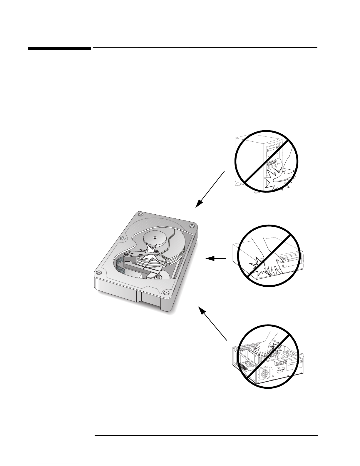
Care of Hard Disk Drives
Care of Hard Disk Drives
HP hard disk drives are delicate and are very sensitive to shocks or
vibration. When installing a hard disk accessory, be careful not to drop or
knock the drive. Any shock may damage the drive and prevent it from
functioning correctly.
Hard disk drives already installed in HP Vectra PCs are also sensitive to
shocks. If the PC’s system unit is knocked or dropped accidentally, this may
cause damage to installed hard disk drives.
Avoid striking the
PC
Don’t move the PC
when powered on
2
Don’t knock the
hard disk during
installation
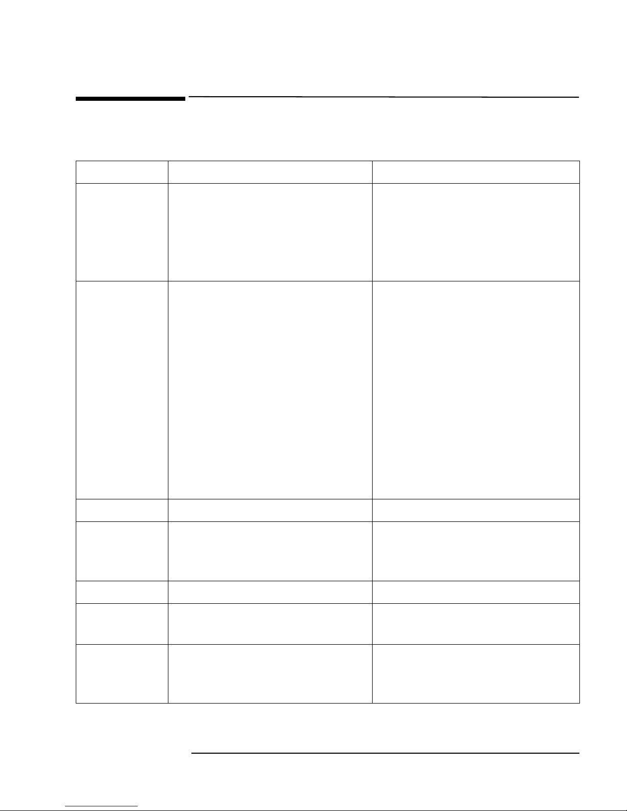
Vectra Product Hardware Comparison
Vectra Product Hardware Comparison
The main feature differences between the two products are shown in bold.
Component HP Vectra VE 4/xxx PC HP Vectra VE 7/xxx PC
Microprocessor
Chipset
Intel Pentium MMX (socket 7), 166,
200, or 233 MHz
16 KB of level-1 cache memory,
256 KB of level-2 cache memory
(integrated on the system board)
Intel Celeron for Slot 1, 266 or
300 MHz
32 KB of level-1 cache memory,
0 KB of level-2 cache memory (based on
the same P6 microarchitecture as
Pentium II processors)
SiS5581 Intel 440EX AGPset (based on Intel
440LX chipset but for the Celeron
processor) with 66 MHz system bus.
● AGP-enabled (Accelerated Graphics
Port) for enhanced graphics performance
in Intel Celeron-based systems
● ACPI (Advanced Configuration and
Power Interface) support
● Ultra ATA (on Primary and Secondary
IDE channels)
● SDRAM memory allows real-time data
transfer from the processor, eliminating
bottlenecks and improving overall
system performance
Super I/O
Memory
Hard Disks
Flexible disk
NS87317 NS309
Up to 192 MB SDRAM 32 MB (standard), 256 MB (maximum),
2.1 or 3.2 GB Ultra ATA SMART II 2.5 or 3.2 GB Ultra ATA SMART II
Standard version without bezel Standard version with bezel (desktop
drive
CD-ROM
24XMAX IDE 32XMAX IDE (without audio jack and
(selected
models)
60 ns SDRAM, two DIMM sockets (nonECC)
and minitower)
volume control switch)
3
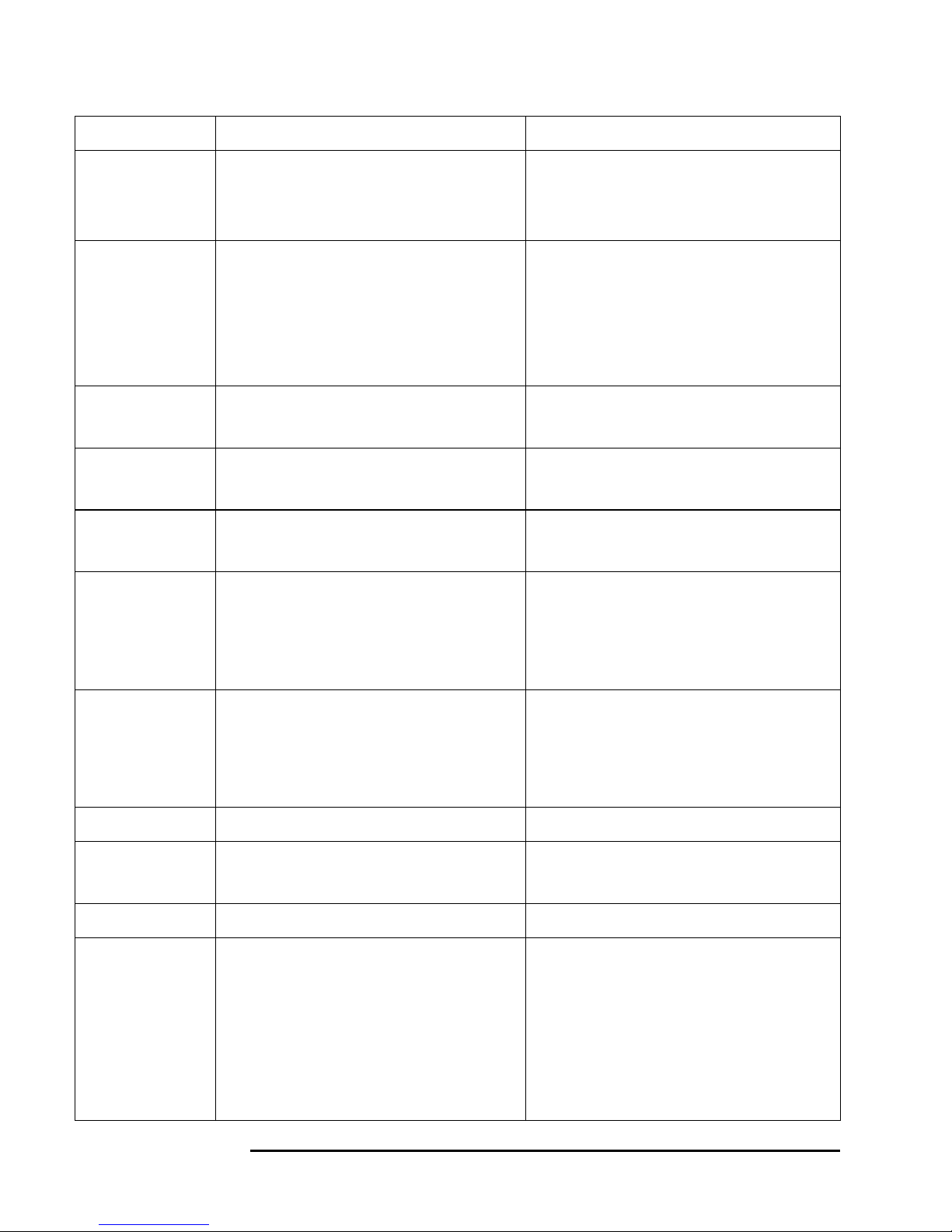
Vectra Product Hardware Comparison
Component
Sound Card
(selected
models)
LAN board
(selected
models)
Graphics
Operating
Systems
Connectors
HP Vectra VE 4/xxx PC HP Vectra VE 7/xxx PC
SoundBlaster Pro-compatible
(Aztech)
SoundBlaster Pro-compatible
(Aztech)
10/100 with RPO 3Com 905B-TX (bundled models) or Intel
10/100Base-T (CAP models) LAN board
with WOL (Wake On LAN) capability,
including Remote Power On/Remote
Wake Up
S3 Trio 64 V2 integrated on the
system board, 2 MB (not upgradeable)
64-bit ATI Rage IIc AGP card,
2 MB EDO (not upgradeable) on AGP bus
Windows 95 (SR 2) Windows NT (Service Pack 3) or
Windows 95 (SR 2.5)
1 Serial, 1 Parallel, Keyboard, Mouse, 2
stacked USB, 15-pin VGA
2 Serial, 1 Parallel, Keyboard, Mouse,
2 stacked USB, 15-pin VGA
Expandability
(desktop)
Expandability
(minitower)
BIOS
Power Supply
Power Savings
Input/Output
Cables
Shelves: 5, including Floppy Disk Drive
(3 front-accessible)
Accessory Slots: 5—2 PCI, 1 ISA,
Shelves: 5, including Floppy Disk Drive
(3 front-accessible)
Accessory Slots: 5—3 PCI, 2 ISA
2 combination PCI/ISA
Shelves: 6 including Floppy Disk Drive
(4 front-accessible)
Accessory Slots: 6—2 PCI, 2 ISA,
Shelves: 6 including Floppy Disk Drive
(4 front-accessible)
Accessory Slots: 5—3 PCI, 2 ISA
2 combination PCI/ISA
Phoenix 4.06 core with HP extensions AMI standard BIOS
Either autoranging 100/240 VAC or
manually switched 115/230 VAC
Manually switched 115/230 VAC, 145 W
continuous output
Normal, standby, sleep Normal, standby, suspend (sleep)
Primary IDE cable: Ultra ATA
Secondary IDE (CD-ROM) cable:
Enhanced IDE
Floppy Disk Drive cable
Primary IDE cable: Ultra ATA
Secondary IDE (CD-ROM) cable:
Standard IDE (only on models supplied
with a CD-ROM drive)
4
Floppy Disk Drive cable
Note: both IDE channels are Ultra ATA

Vectra Product Hardware Comparison
Component
Compliancy
System
Management
HP Vectra VE 4/xxx PC HP Vectra VE 7/xxx PC
DMI 2.0 DMI 2.0 / SMBIOS 1.x
PC97 Phase 1
EPA Energy Star
HP TopTools 3.0, HP DiagTools 2.0 HP TopTools 3.0, HP DiagTools 2.0
Features:
● Inventory database (DMI 2.0).
Detailed asset information can be
gathered from anywhere on the network
and stored in a database.
● Hardware diagnostics (HP DiagTools
2.0). Comprehensive set of hardware
diagnostics tools.
● Actions on alerts. HP TopTools’ 3.0
hardware diagnostics program can
generate alerts and DMTF-standard
support tickets.
● Remote power on/off. The HP Vectra
VE can be remotely powered on/off.
Where to find information
For more information, refer to the Hewlett-Packard MIS Kit for this product,
available at the HP World Wide Web site:
http://www.hp.com/go/vectrasupport/
The MIS kit for this PC includes:
• User’s Guide — Setting up information for the PC.
• Upgrade and Maintenance Guide — describes in detail how to open the
package and install accessories. It also has detailed troubleshooting
information.
• Network Administrator’s Guide — network driver installation
information for network administrators.
• Service Handbook Chapters — information on upgrade and replacement
parts, including HP part numbers. Beep codes are explained in an
Appendix of the HP Vectra Service Handbook (13th Edition).
5
Desktop Models Package
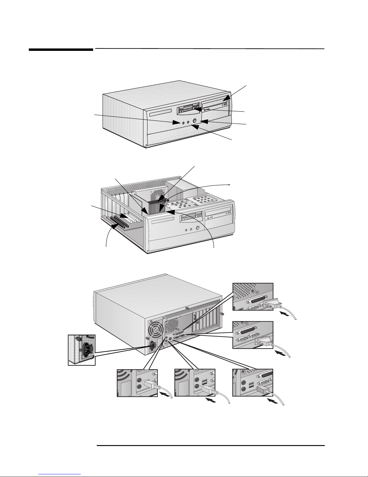
Desktop Models Package
Front view
Hard disk
activity light
Front view with
cover removed
Refer to page 8 for more
information about the
system board
Three PCI slots
AGP slot
Two ISA slots
CD-ROM drive
(some models)
Flexible disk drive
Power on/off button
Power on status light
Celeron Processor
Two SDRAM memory module slots
System board switches
Rear view
Voltage
Selection
Switch
Parallel Connector
2 Serial Connectors
Mouse (top connector)
Keyboard
(bottom connector)
2 USB Connectors
6
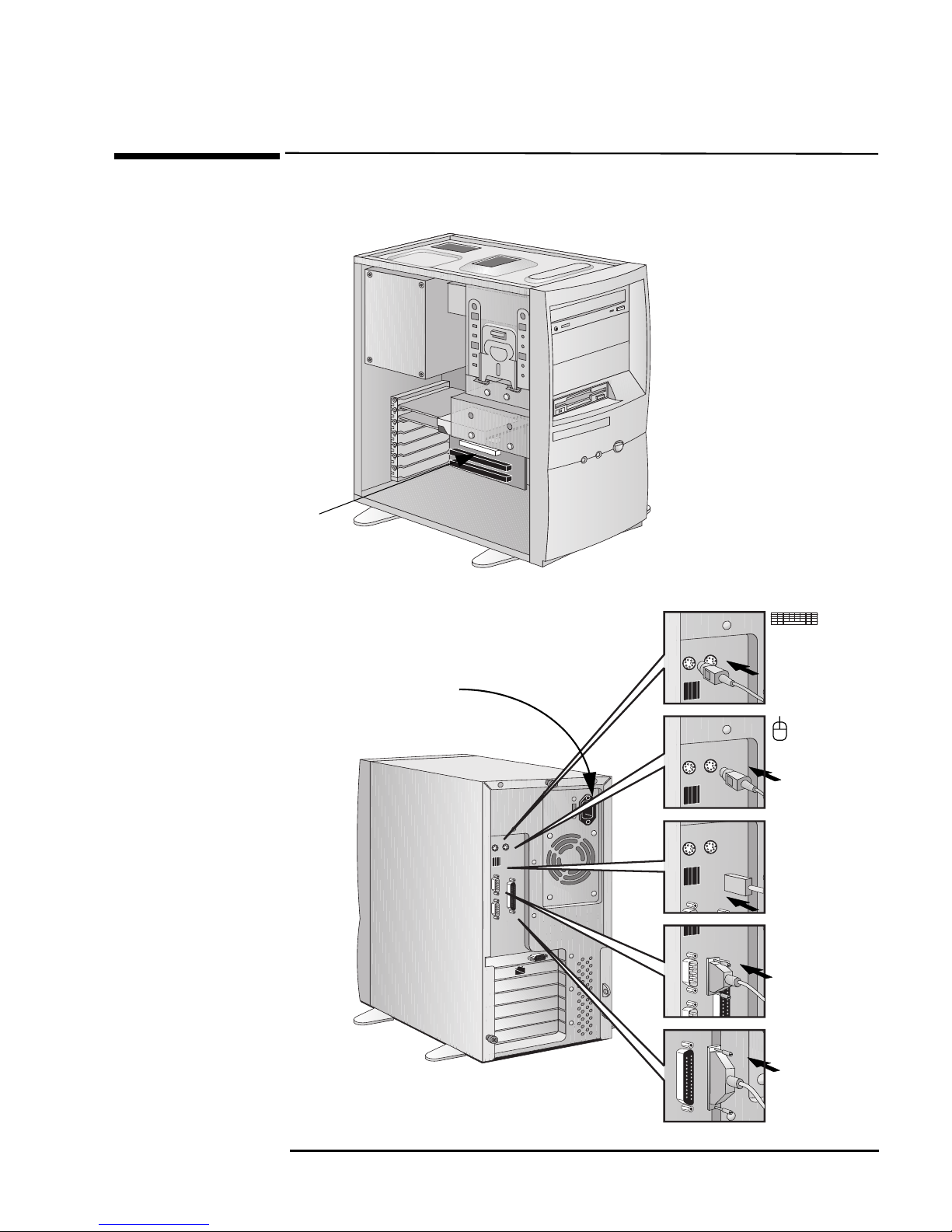
Front view with
cover removed
Same system board as
desktop models
Minitower Package
Minitower Package
Rear view
Keyboard
(left connector)
Voltage
Selection
Switch
Mouse (right
connector)
2 USB
Connectors
2 Serial
Connectors
Parallel
Connector
7
 Loading...