

HP Vectra VE5 2, Vectra VE 5/xxx, Vectra VE 5/xx User Manual

HP Vectra VE 5/xx
Series 2
User's Guide

NOTICE
Information contained in this document is subject to change without notice.
Hewlett-Packard makes no warranty of any kind with regard to this material, including,
but not limited to, the implied warranties of merchantability and fitness for a particular
purpose. Hewlett-Packard shall not be liable for errors contained herein or for incidental
or consequential damages in connection with the furnishing, performance, or use of
this material.
Hewlett-Packard assumes no responsibility for the use or reliability of its software on equipment
that is not furnished by Hewlett-Packard.
This document contains proprietary information which is protected by copyright. All rights are
reserved. No part of this document may be photocopied, reproduced, or translated into another
language without the prior written consent of Hewlett-Packard Company.
Centronics® is a U.S. registered trademark of Centronics Data Computer Corporation.
Matrox® is a registered trademark of Matrox Electronic Systems Ltd.
MGA™ and Millennium™ ae trademarks of Matrox Graphics Inc.
Microsoft® and MS-DOS® are registered trademarks of Microsoft Corporation. Microsoft ,
Windows®, and Windows® 95 are products of Microsoft Corporation.
Novell® and Netware® are registered trademarks of Novell Inc.
O/S2™ is a trademark of International Business Machines Corporation.
Pentium™ is a trademark of Intel Corporation.
UNIX® is a registered trademark of UNIX System Laboratories Inc. in the U.S.A. and other
countries.
©1996 Hewlett-Packard Company

Table of Contents
NOTICE 4
WELCOME TO YOUR HP VECTRA PC 8
1 SETTING UP YOUR PC 9
UNPACKING YOUR PC 9
CONNECTING THE MOUSE, KEYBOARD, AND DISPLAY 11
CONNECTING A PRINTER 11
CONNECTING THE POWER CORDS 12
STARTING THE PC FOR THE FIRST TIME 13
CREATING MASTER DISKETTES 16
2 USING YOUR PC 17
STARTING AND STOPPING YOUR PC 17
STARTING YOUR PC 17
STOPPING YOUR PC 18
THE HP VECTRA KEYBOARD 18
ADVANCED POWER MANAGEMENT 19
HP USER TOOLS 19
DESKTOP MANAGEMENT INTERFACE 19
3 HOW TO INSTALL ACCESSORIES IN YOUR PC 20
SUPPORTED HP ACCESSORIES 20
REMOVING THE COVER 22
REPLACING THE COVER AFTER INSTALLING ACCESSORIES 23
MOVING AND REPLACING THE POWER SUPPLY 23
REPLACING THE POWER SUPPLY AFTER INSTALLING
ACCESSORIES 2 4
INSTALLING MEMORY 25
MAIN MEMORY MODULES 25
INSTALLING AN OPTIONAL CACHE MEMORY MODULE 27
INSTALLING A VIDEO MEMORY UPGRADE 28
INSTALLING ACCESSORY BOARDS 29
CONFIGURING ACCESSORY BOARDS WITH PLUG AND PLAY 29
CONFIGURING NON-PLUG AND PLAY ISA ACCESSORY BOARDS 29
INSTALLING THE BOARD 30
INSTALLING MASS STORAGE DEVICES 33
CONFIGURING A DEVICE AFTER INSTALLATION 33
CONNECTING IDE DEVICES 33
INSTALLING A FLEXIBLE DISK DRIVE OR A CD-ROM DRIVE IN THE
MIDDLE SHELF 35
INSTALLING AN IDE HARD DISK DRIVE IN THE REAR SHELF 38
INSTALLING AN IDE HARD DISK DRIVE IN THE BOTTOM SHELF 40
INSTALLING A 5.25-INCH DISK DRIVE IN THE BOTTOM SHELF 43
INSTALLING A 3.5-INCH DISK DRIVE IN THE BOTTOM SHELF 46

INSTALLING AN UPGRADE PROCESSOR 49
INSTALLING THE SECURITY BRACKET 50
4 THE HP SETUP PROGRAM 52
USING THE HP SETUP PROGRAM 52
STARTING THE SETUP PROGRAM 52
UNDERSTANDING THE SETUP PROGRAM 54
SETTING PASSWORDS 59
SETTING PASSWORDS 59
AFTER INSTALLING AN IDE DRIVE 61
IF YOU LOSE THE KEY 62
5 TROUBLESHOOTING YOUR PC 63
SOLVING PROBLEMS 63
IF YOUR PC DOES NOT START PROPERLY 63
DISPLAY IS BLANK AND THERE ARE NO ERROR MESSAGES 63
IF YOU ARE UNABLE TO CHANGE ANY VALUES IN
IF A POST ERROR MESSAGE IS DISPLAYED 65
IF YOUR PC HAS A HARDWARE PROBLEM 66
DISPLAY DOES NOT WORK PROPERLY 67
IF YOUR KEYBOARD OR MOUSE DOES NOT WORK 68
IF YOUR PRINTER DOES NOT WORK 68
IF THE FLEXIBLE DISK DRIVE DOES NOT WORK 69
IF THE HARD DISK DOES NOT WORK 69
IF THE CD-ROM DRIVE DOES NOT WORK 70
IF AN ACCESSORY BOARD DOES NOT WORK 70
IF YOUR PC HAS A SOFTWARE PROBLEM 71
IF YOUR APPLICATION SOFTWARE DOES NOT WORK 71
IF POWER MANAGEMENT DOES NOT WORK 72
IF THE DATE AND TIME ARE INCORRECT 72
CHANGING THE BATTERY 73
IF THE SCSI HARD DISK STOPS WORKING 74
IF YOU LOSE THE KEY 74
SETUP
64
6 TECHNICAL INFORMATION 75
SPECIFICATIONS 75
FEATURES 76
POWER CONSUMPTION, WINDOWS 3.11 76
POWER CONSUMPTION, WINDOWS 95 77
IRQS, DMAS, AND I/O ADDRESSES USED BY YOUR PC 78
AVAILABLE VIDEO RESOLUTIONS 79
THE PC'S MEMORY MAP 80
THE PC'S REAR CONNECTORS 81
SYSTEM BOARD CONNECTORS AND SWITCHES 82
RECYCLING YOUR PC 8 3

7 HEWLETT PACKARD SUPPORT AND
INFORMATION SERVICES 84
INTRODUCTION 84
YOUR HP AUTHORIZED RESELLER 84
HP SUPPORTPACK 85
HP SUPPORT ASSISTANT CD-ROM 85
HEWLETT-PACKARD INFORMATION SERVICES 85
HP FORUM ON COMPUSERVE 85
HP FORUM ON AMERICA ONLINE 86
HP BBS LIBRARY 86
INTERNET—FTP LIBRARY SERVICE 8 7
ACCESS HP WORLD WIDE WEB SITE 87
HP FAXBACK ON DEMAND—HP FIRST 8 7
HP AUDIO TIPS (USA ONLY) HP AUTOMATED SUPPORT DIRECTORY 87
ORDERING DRIVERS AND BIOS ON DISKETTE 88
HP SUPPORT SERVICES 88
HEWLETT-PACKARD TELEPHONE SUPPORT 8 9
LIFELINE TELEPHONE SUPPORT 90
HP NETWORK PHONE-IN SUPPORT SERVICE (NPS) 9 0
SUMMARY 91
HEWLETT-PACKARD MARKETING HEADQUARTERS 92
HP WORLD WIDE WEB SERVER 92
HP ANONYMOUS FTP SERVER 92
EUROPEAN CUSTOMER SUPPORT CENTER 92
HP WORLD WIDE WEB SERVER 93
HP ANONYMOUS FTP SERVER 93
EUROPEAN CUSTOMER SUPPORT CENTER 93
GLOSSARY 94
7 REGULATORY INFORMATION AND WARRANTY97
REGULATORY INFORMATION 97
FCC (FOR USA ONLY) 97
HP HARDWARE WARRANTY 99
HP SOFTWARE PRODUCT LICENSE AGREEMENT AND SOFTWARE &
PRODUCT LIMITED WARRANTY 1 01

WELCOME TO YOUR HP VECTRA PC
Congratulations on the purchase of your new Hewlett-Packard desktop PC. Your highperformance PC provides:
• a Pentium™ processor in a Zero Insertion Force (ZIF) socket for easy processor upgrades
• an optional level-two cache of 256 KB for high performance
• a main memory of 8 MB, upgradeable to 128 MB
• an Ultra VGA PCI (Peripheral Component Interconnect) video controller with 1 MB of
video memory (upgradeable to 2 MB)
• an integrated Enhanced IDE (Integrated Drive Electronics) controller on the PCI bus
supporting Fast IDE and Standard IDE
• three front-access drive shelves (one can be used as an internal shelf)
• one internal drive shelf
• four free slots for accessory boards:
• one 32-bit PCI (Peripheral Component Interconnect) slot
• one 16-bit ISA (Industry Standard Architecture) full length slot
• one 16-bit ISA short slot (16 cm/6.3 inch maximum length)
• one combination ISA or PCI slot
• one parallel port and two serial ports
• preloaded HP utilities to ease system configuration tasks
• BIOS stored in Flash ROM
• BIOS support for ISA “Plug and Play”
• pre-installed Operating system and Software.
Your HP Vectra has other important attributes:
• DMI compliant
• designed for Windows® 95
• Vectra Ergonomic Power Solution — Windows 95 soft power-down using the mouse, and
keyboard power-on
• Energy Star compliant power management
The PC range described in this manual has a power saving capability which complies with
the Environment Protection Agency's (EPA) 30 watt maximum power consumption in
sleep mode, with the exception of those models which are fully loaded multimedia PCs.
The fully loaded multimedia PCs also have energy saving capabilities, but use slightly
more than the maximum 30 watt limit in power saving mode, required for the Energy Star
label approval.
1 SETTING UP YOUR PC
Typical Display
This chapter leads you through the first time installation of your HP Vectra PC.
UNPACKING YOUR PC
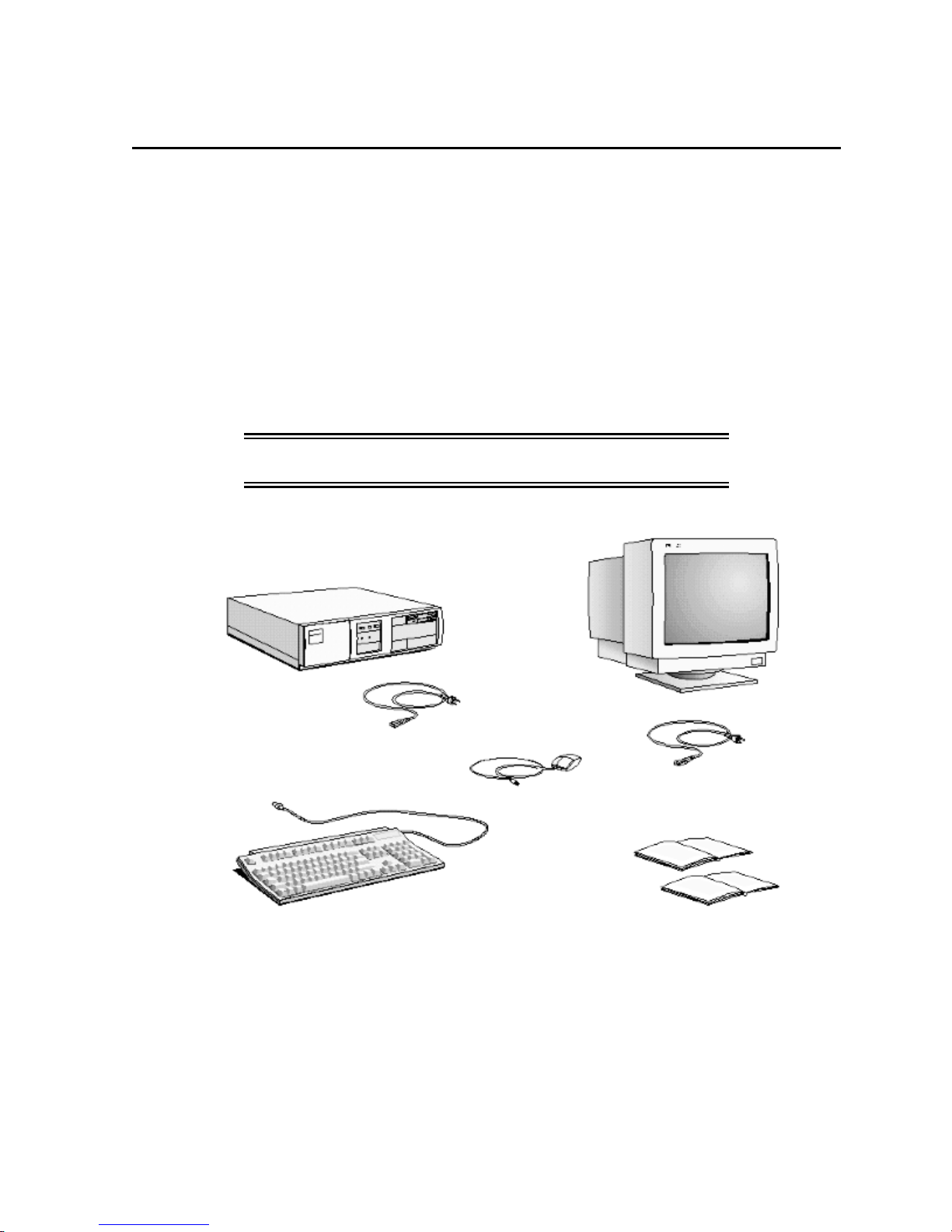
1 When you receive your PC, unpack all the components:
• the computer and power cord
• the display and its cables
• the keyboard and mouse
• the manuals.
On some models, the operating system software, drivers, and HP User Tools are preloaded on
the hard disk.
WARNING: If you have any doubt that you can lift the PC or
display safely, do not try to move it without help.
Computer
Computer Power Cord
Keyboard
Mouse
Display Power Cord
Manuals
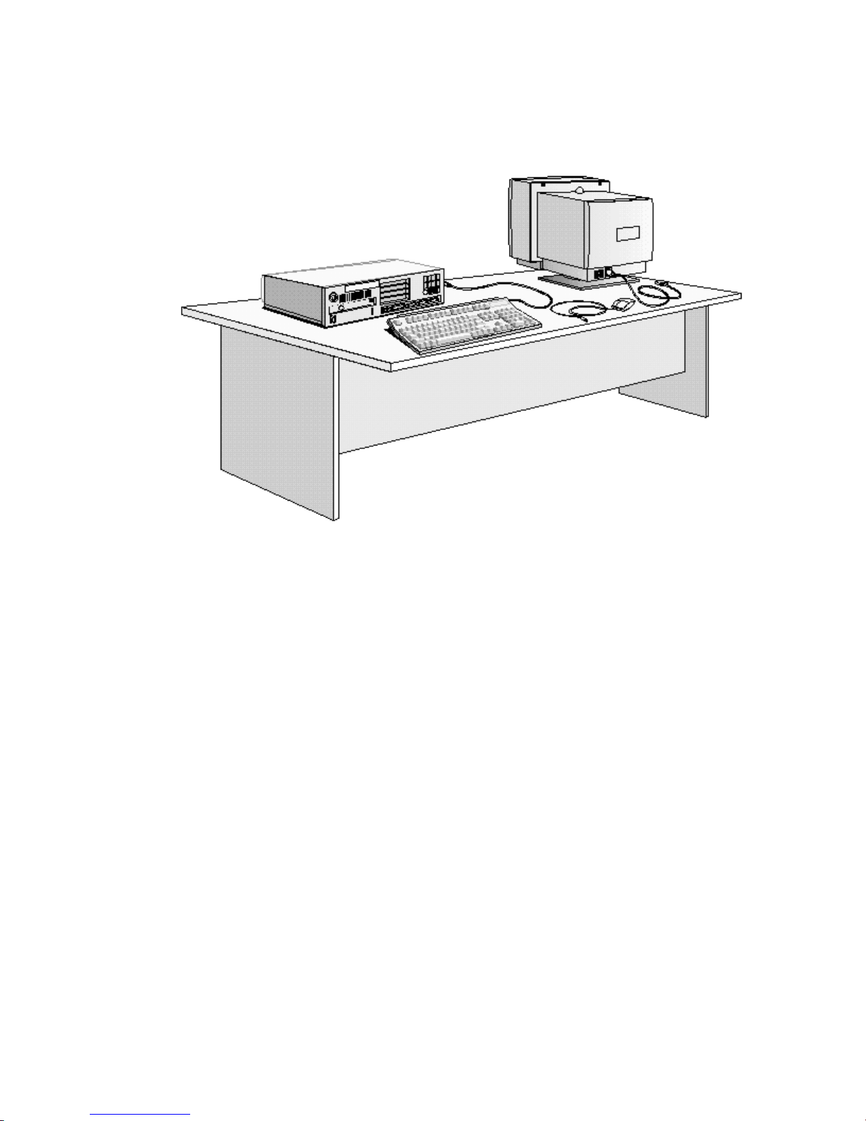
2 Place the PC on a sturdy desk near to easily accessible power outlets, with enough space for
the keyboard, mouse, and any other accessories.
3 Position the PC so that its rear connectors are easily accessible.
4 Place the display on top of the computer. If you have a large display, place it next to the
computer. Refer to the display’s manual for information about the display.
Installation Tools
No tools are required to set up your PC. However, if you plan to install a disk drive or an
accessory board in your PC, you will need a flat-blade screwdriver. For further information
about installing accessories, refer to chapter 3, “
How to Install Accessories In Your PC
”.
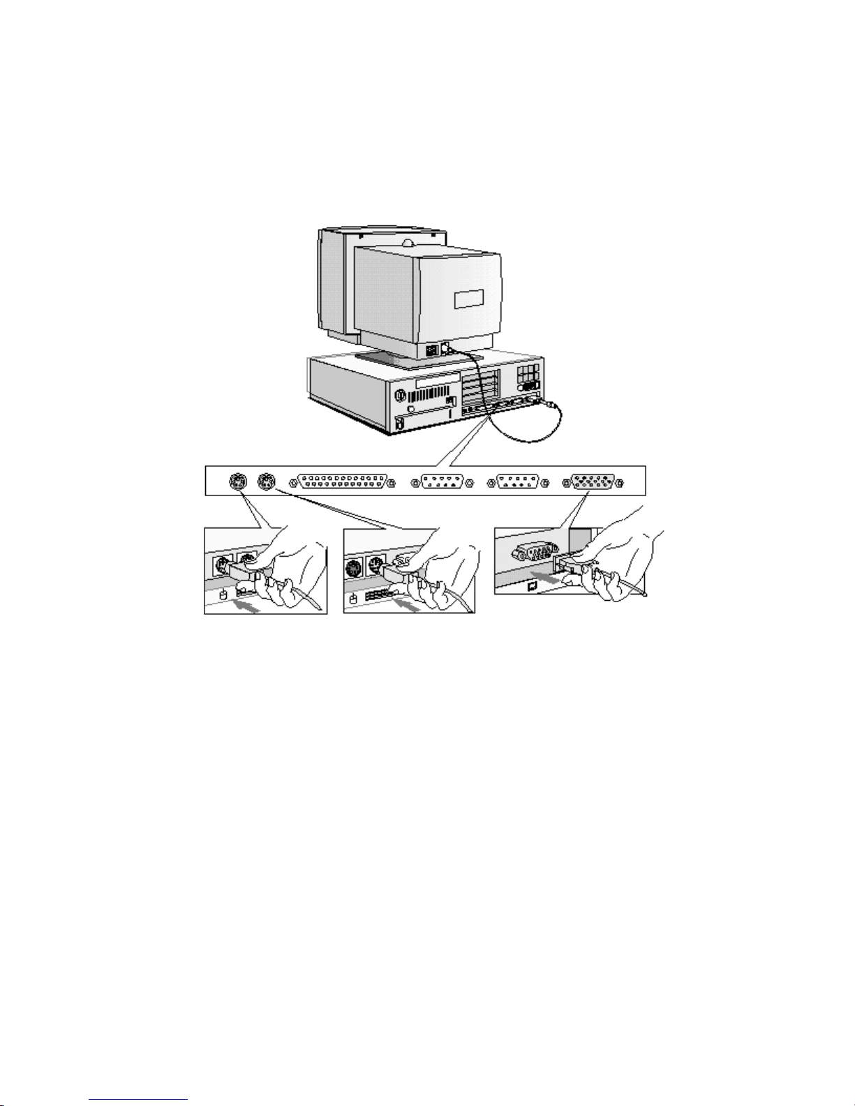
CONNECTING THE MOUSE, KEYBOARD, AND DISPLAY
1 Connect the mouse, keyboard, and display to the back of the computer.
are shaped to go in one way only
2 Tighten the display cable attachment screws.
.
The connectors
Mouse Keyboard Display
CONNECTING A PRINTER
Connect the printer cable to the back of the computer and tighten the attachment screws. Use
the connector labeled:
• Parallel (25-pin parallel connector) for a parallel device
• Serial A (9-pin serial connector) for a serial device
• Serial B (9-pin serial connector) for a second serial device.
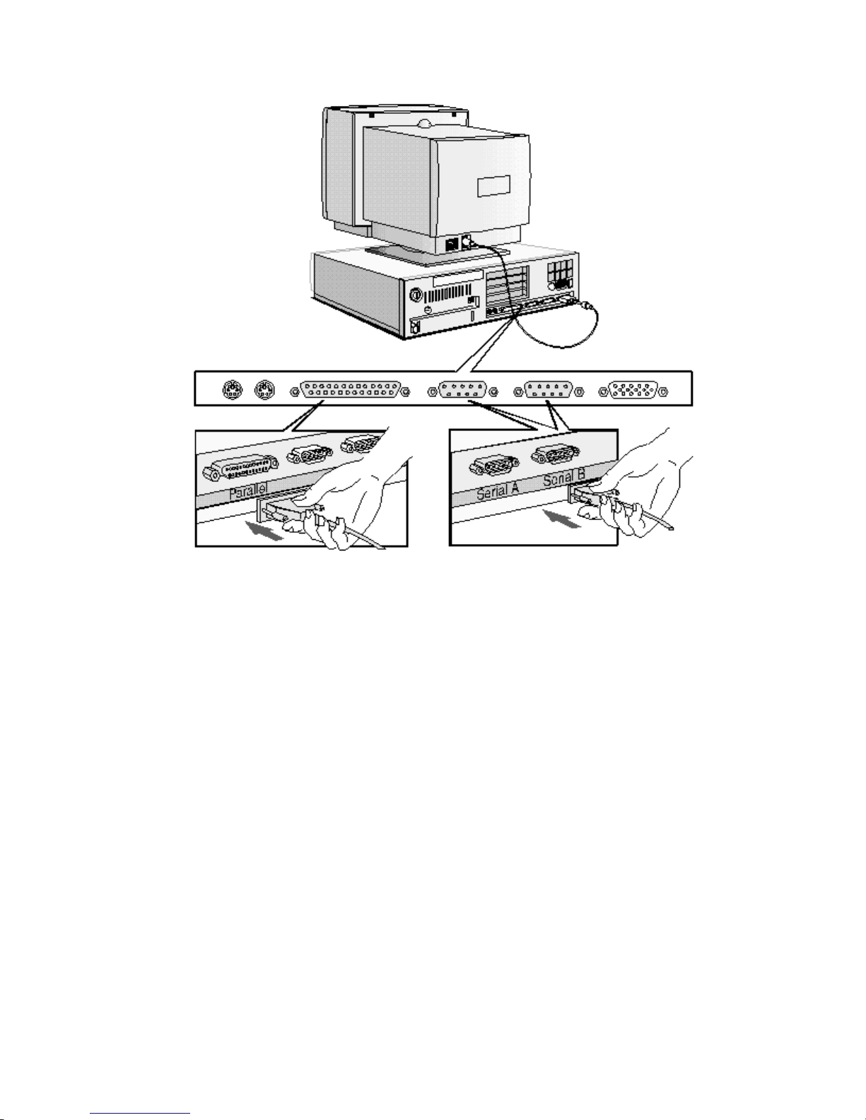
Parallel Connector Serial Connector
CONNECTING THE POWER CORDS
1 If fitted, remove the label covering the computer’s power connector.
2 Connect the power cords to the display and the computer.
3 Connect the display’s power cord and the computer’s power cord to a grounded outlet.
The connectors are shaped to go in one way only
(
.)
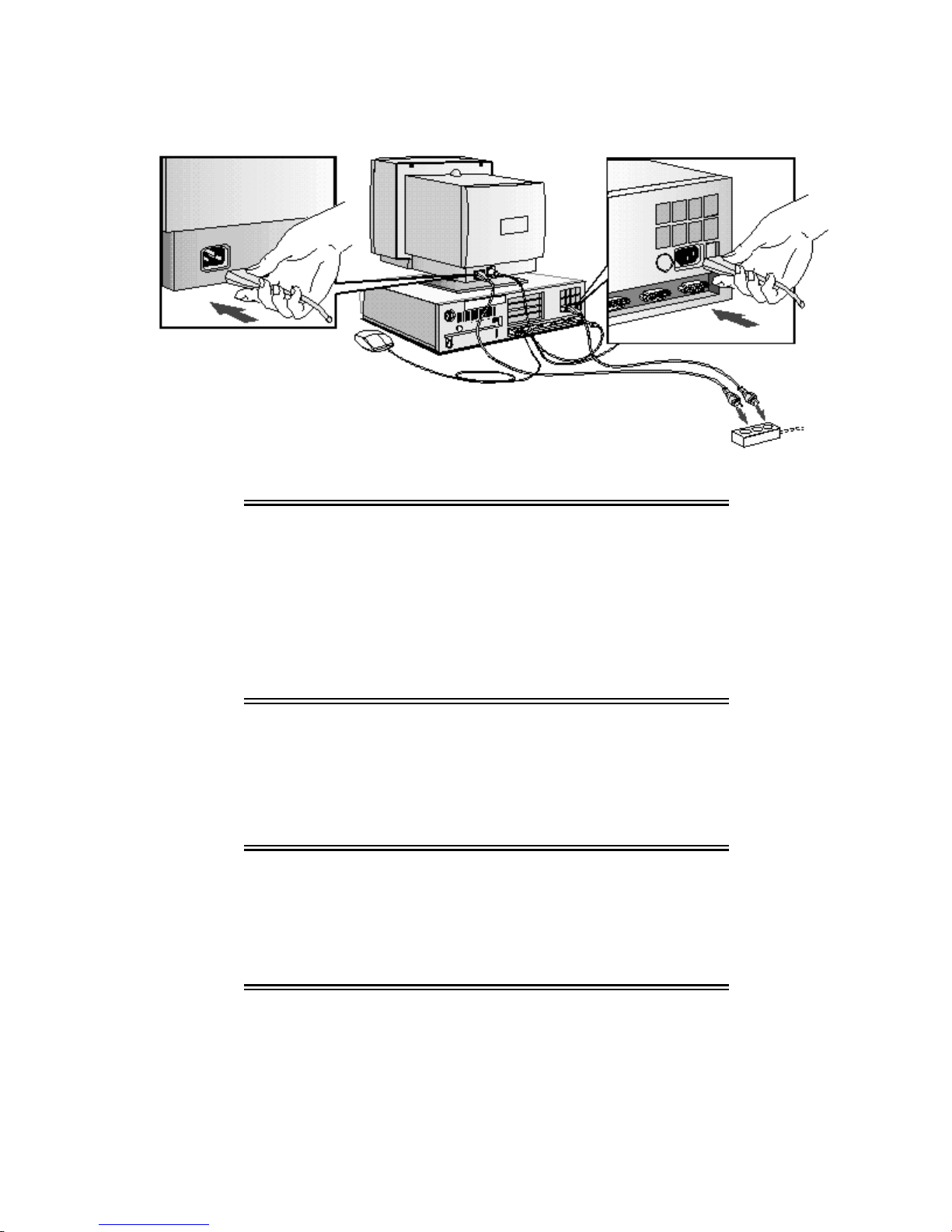
Display Power Cord Computer Power Cord
Grounded Outlet
WARNING: For your safety, always connect the equipment to
a grounded wall outlet. Always use a power cord
with a properly grounded plug, such as the one
provided with this equipment, or one in
compliance with your national regulations.
This PC is disconnected from the power by
removing the power cord from the power outlet.
This means the PC must be located close to a
power outlet that is easily accessible.
STARTING THE PC FOR THE FIRST TIME
If your PC has preinstalled software, it is initialized the first time you start the PC. The software
initialization process takes approximately three minutes. This process sets up the software in
your language and sets up your software to use the hardware installed in your computer (you
can change the settings after the software has been initialized).
CAUTION: Depending on which model PC you have, you may
also be asked to select which operating system you
want to use, for example Windows 3.11 or Windows
95. Once you have confirmed your selection of the
operating system, you cannot change that selection.
The operating system that you have NOT chosen will
be deleted from the computer’s hard disk.
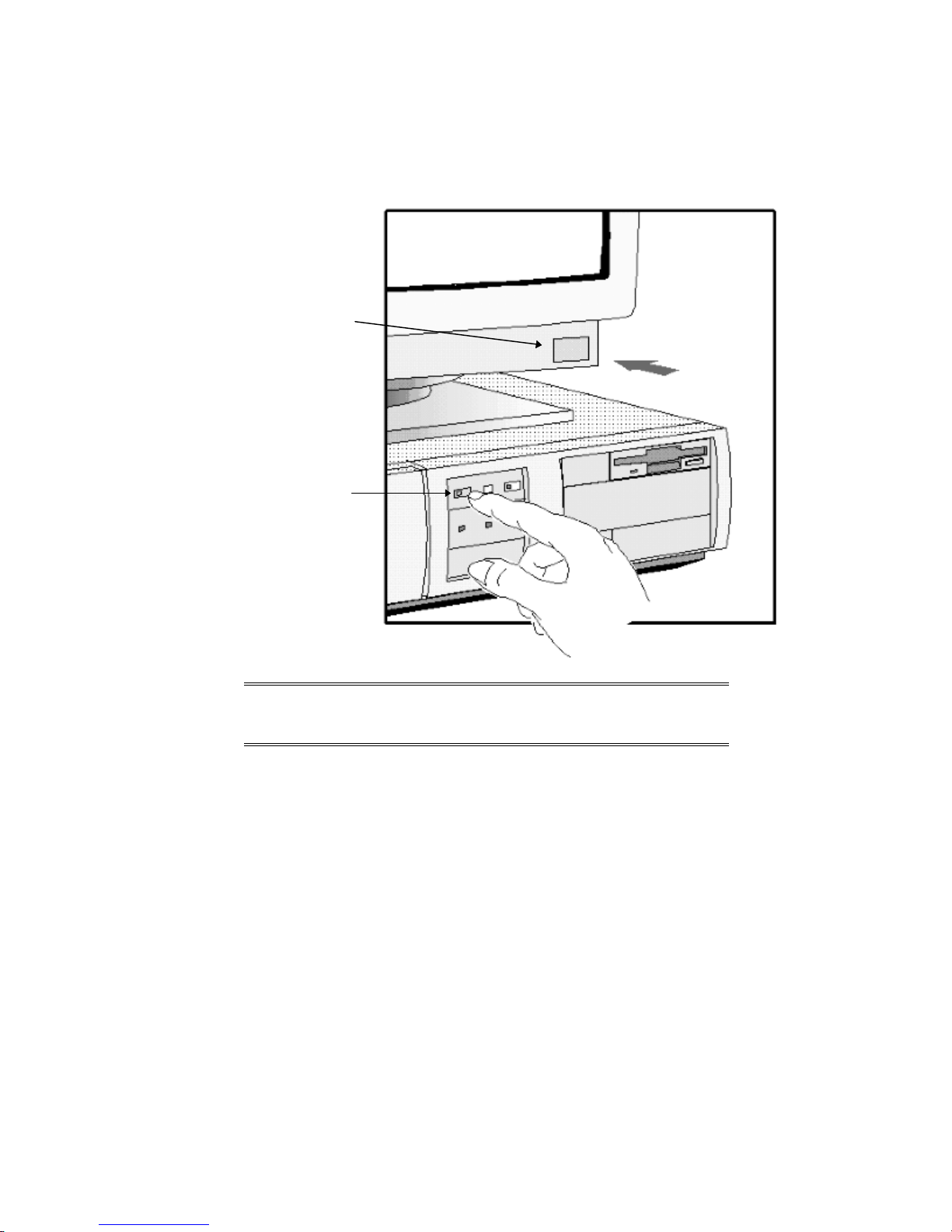
To initialize your software
1 Switch on the display first, and then the PC (this will allow your PC to recognize the type
of display you have).
Switch on the Display
Then switch on the PC
NOTE Do NOT switch OFF the PC while the software is
being initialized for the first time as this could cause
unexpected results.
When the PC is switched on, the Vectra Logo is displayed. The PC performs a Power-OnSelf-Test (POST). Press [ESC] if you want to view the POST information.
If an error is detected during the Power-On-Self-Test, the PC will automatically display the
error. If this occurs, refer to "If a POST Message is Displayed" in chaper 5.
2 The software initialization routine starts. It displays the software license agreement, gives
you an opportunity to read Working in Comfort (ergonomic advice for computer users),
and then asks questions about the PC. For example:
• The name of the person who will use the PC and your company name. (If necessary,
the name of the user can be modified later.)
• The current date and time.
• The type of printer (for example, HP LaserJet 4M). This is shown on the front of the
printer. You also need to enter the connection used by the printer.

• The model number of your display. The display’s model number is shown on the cover
of the manual supplied with the display and on a label on the rear of the display.
• You may also be asked to select which operating system you want to use, Windows
3.11 or Windows 95. Once you have confirmed your selection of the operating system,
you cannot change that selection. The operating system that you have NOT chosen
will be deleted from the computer’s hard disk
3 While the initialization program is running, you can complete the Warranty Registration
card that you will find inside the back of this manual.
When the initialization routine has finished, click on OK and the PC will restart.
4 When Your PC has restarted:
• Set the keyboard to a comfortable position.
• Adjust the display screen’s brightness and contrast to suit your needs. If the picture does
not fill the screen or is not centered, adjust it using the controls on the display. Refer to the
display’s manual for details.
Adjust Brightness and Contrast
Your Display
may be different
from the display
shown here

CREATING MASTER DISKETTES
NOTE It is very important that you create master diskettes
for your preloaded software as soon as
possible.These diskettes will be your unique means
of regenerating your system if you need to restore
the preloaded software onto your PC. Use new
diskettes to create master diskettes.
Windows 3.11
Choose this utility in the HP User Tools group in Program Manager and follow the screen
messages, which will tell you how many diskettes you need.
Windows 95
Use the Microsoft Create System Disk utility. Refer to the Windows 95 documentation for
further information.
Other Operating Systems
Refer to the documentation for your operating system.
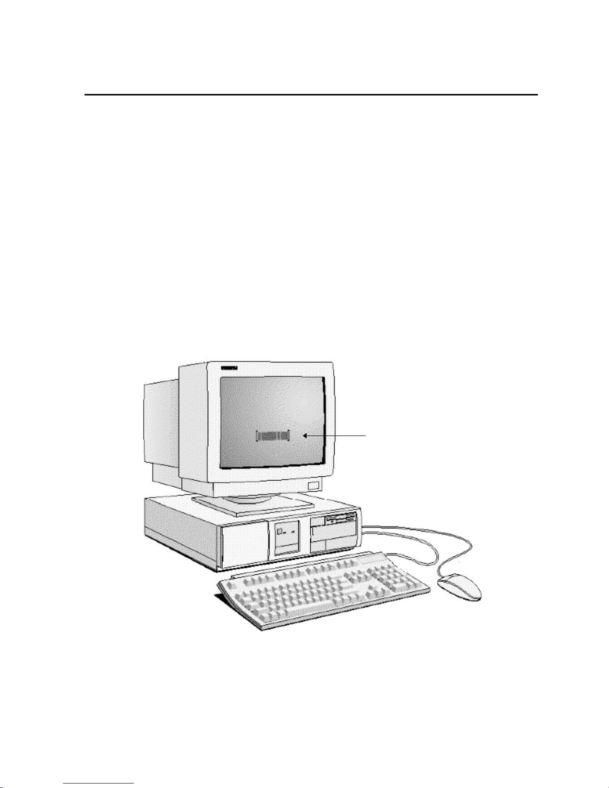
2 USING YOUR PC
Password
Prompt
This chapter explains how to use the HP Vectra PC to increase your productivity.
STARTING AND STOPPING YOUR PC
STARTING YOUR PC
1 Before you start your PC, always switch on the display first.
2 Start your PC in one of these ways:
• press the power button on the front panel
• press the space bar.
When you switch on the computer, the computer carries out the Power-On-Self-Test
(POST) while the Vectra logo is displayed. If you wish to view the POST details, press
[ESC]. If there is an error in the POST, the error will automatically be displayed.
3 If you have set a password in the PC’s Setup program, the password prompt displays after
the POST has completed. If the Password prompt is displayed, type your password and
press [ENTER] to be able to use the PC.
STOPPING YOUR PC
Stopping the PC when using Windows 3.11
To stop the PC, make sure that you have exited all programs and then exited Windows before
pressing the power button on the control panel.
Stopping the PC when using Windows 95
To stop or shut down the PC:
1 Click on Start.
2 Click on Shut Down.
3 Click on Shut down the computer.
You can return the PC to full power mode by pressing the space bar.
Other Operating Systems
For other operating systems refer to the operating system manual for details of how to exit the
operating system.
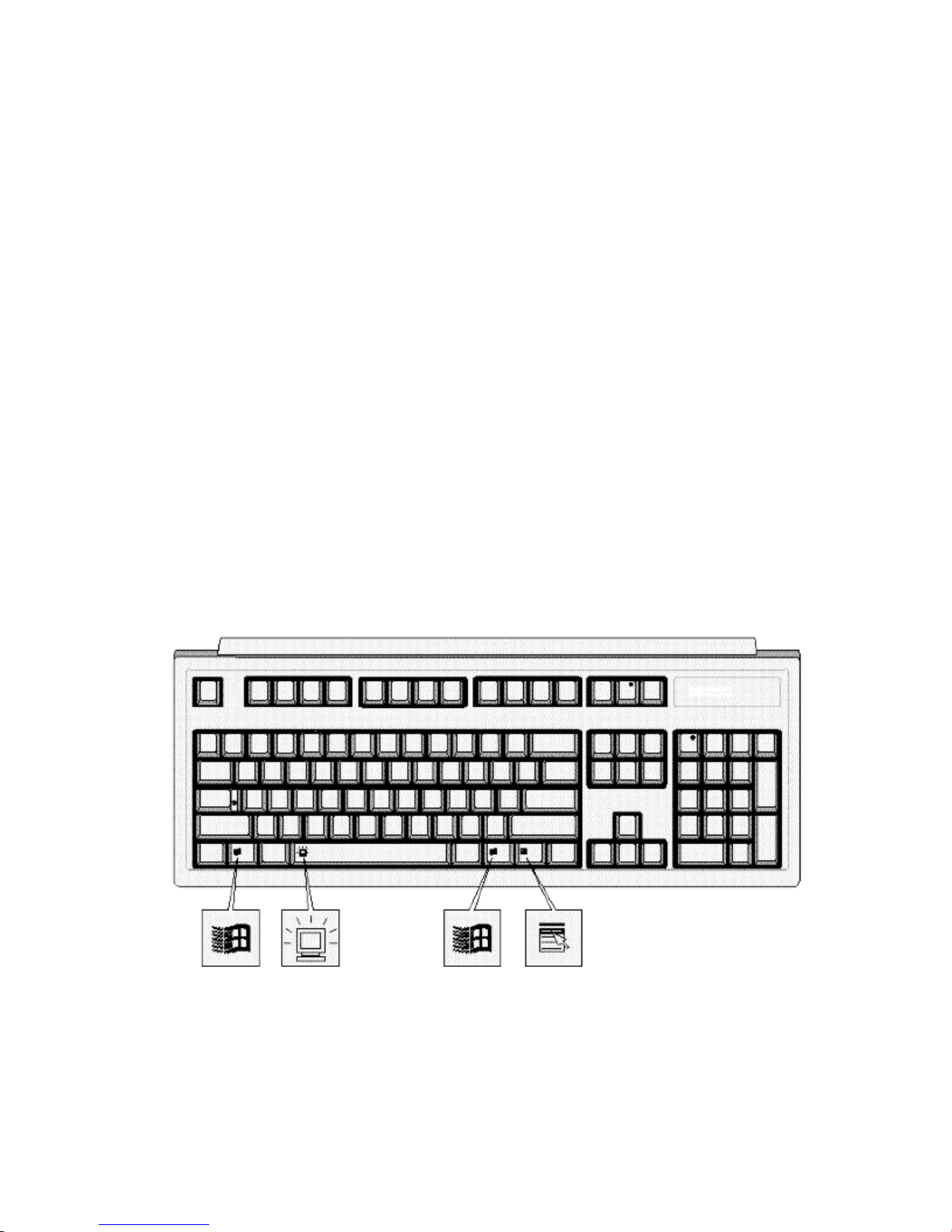
THE HP VECTRA KEYBOARD
The HP Vectra keyboard has three keys that give speedy access to Windows 95 functions.
These keys have icons indicating what these functions are. The space bar also has an
additional function, the Power-On function, which is not specific to Windows 95.
The Windows Icon
You can display the Windows 95 Start menu by pressing either of the two Windows keys,
which are on either side of the space bar. Refer to Windows 95 documentation for further
information about Windows 95.

The Application Key
The Application key allows you to access all the same functions as the right mouse button. It
can be used to copy and move files, to access shortcut menus and get Help information. The
Application key can also be programmed by your software.
The Power-On Icon on the Space Bar
The Power-On function enables you to start your PC by pressing the space bar. This function is
not specific to Windows 95, but is available whatever your operating system. The option can be
Setup
enabled or disabled in
with system board switch 9 (refer to "System Board Connectors and Switches" in chapter 6).
(default is “enabled”). You can also enable or disable this function
ADVANCED POWER MANAGEMENT
Power management enables you to reduce the PC’s power consumption when you are not
using it.
The following two power management modes are supported in Windows 3.11 and Windows 95:
• Standby Mode, which significantly reduces power consumption. In this mode, the display
is suspended. The system remains fully working, but runs slower. Any user event, such as
from the mouse or keyboard, will instantly cause the system to resume.
• Sleep Mode, which reduces power consumption to a minimum. Graphics, the processor,
and hard disks (IDE and SCSI) are stopped (placed in their respective off modes). While
the system is in this mode, the modem will still operate and the PC can receive faxes. A
key press will cause the system to resume to full mode within a few seconds.
Windows 95 supports a third mode, Shut Off Monitor.
Refer to your operating system documentation for detailed information about how to implement
power management. Also refer to "If Power Management Does Not Work", on page 89.
HP USER TOOLS
If your PC has preinstalled software, you will find HP User Tools on your system. These tools
help you to both configure your system and improve the functionality of your PC. They include
such items as configuring printers and setting video modes.
DESKTOP MANAGEMENT INTERFACE
Your PC supports the Desktop Management Interface (DMI). The DMI lets an application
request information about your computer. For example, an application can use the DMI to view:
• the hardware and software components installed in your PC
• the operating system used by your PC
• the number of available accessory board slots.
3 HOW TO INSTALL ACCESSORIES IN YOUR PC
This chapter explains how to install accessories, such as extra memory, accessory boards, and
additional disk drives, in your PC.
SUPPORTED HP ACCESSORIES
This chapter describes how to install memory, mass storage devices, and accessory boards in
your PC.
Refer to "Hewlett Packard Support and Information Services" (chapter 7) for information about
how to obtain an up-to-date list of supported devices.
One internal mass storage device
630 MB IDE, order D2929A or
1.2 GB IDE, order D2930A
Up to three front access drives, for accessories such as:
5.25 inch 1.2 MB flexible disk drive, (half height) order D2881B
3.5 inch 1.44 MB flexible disk drive, (one third height) order D2035B
Mounting Rails can be ordered for front
access devices:
5.25 inch disk drive rails, order D2880A
3.5 inch disk drive rails, order D3566A
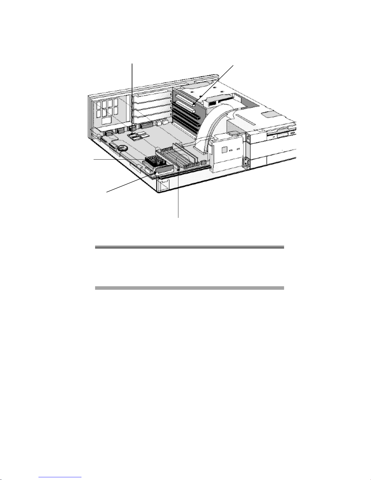
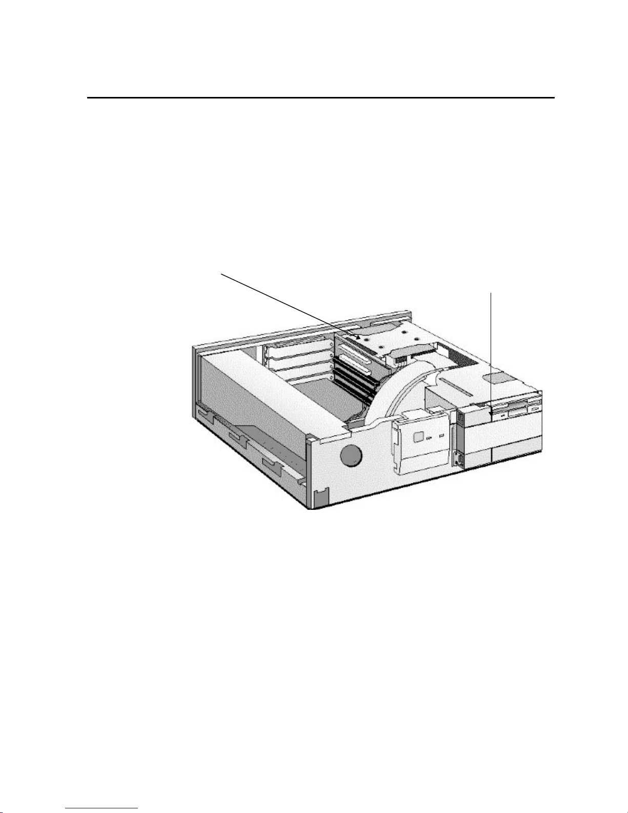
1 MB Video Memory Upgrade
Processor
Processor Voltage
Shorting Block
Up to four accessory boards
Top two: PCI
Bottom three: ISA
Main Memory Modules (32-bit EDO, 60 ns)
8 MB kit (2 x 4 MB modules) order D3646A
16 MB kit (2 x 8 MB modules) order D3647A
32 MB kit (2 x 16 MB jmodules) order D3648A
256 KB Level 2 Cache Memory (optional)
Order D3659A
WARNING: For your safety, never remove the PC’s cover
without first removing the power cord from the
power outlet, and any connection to a
telecommunications network. Always replace the
cover on the PC before switching it on again.
REMOVING THE COVER
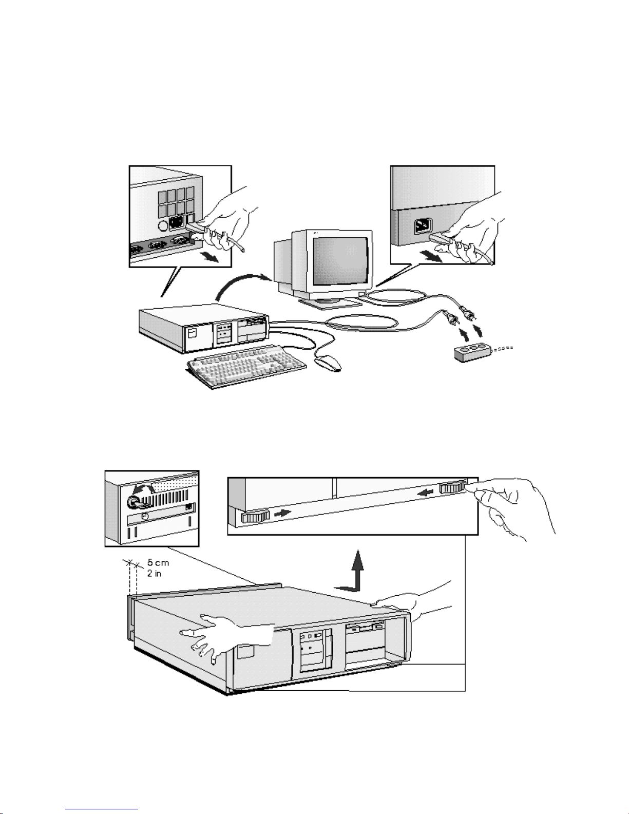
1 Switch off the display and the PC.
2 Disconnect the power cords from the power outlets, the PC, and the display. Disconnect
any connection to a telecommunications network. Then remove the display.
3 If necessary, unlock the cover using the key provided with the PC.
4 Slide the two tabs on the front of the computer inwards. Firmly slide the cover
forward 5 cm (2 inches), and lift it up and off the computer.
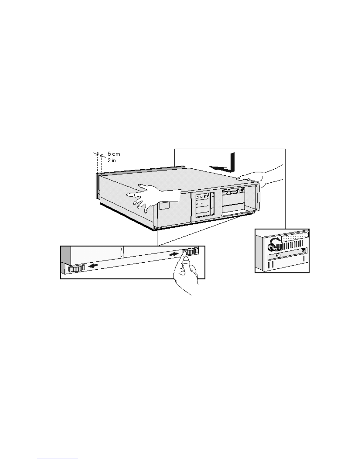
REPLACING THE COVER AFTER INSTALLING ACCESSORIES
1 Check that you have installed all your accessories.
2 Make sure that all internal cables are properly connected and safely routed so they will not
be entangled when you replace the cover.
3 Ensure the cover lock is unlocked and the tabs are inwards.
4 Lower the cover onto the computer, and firmly slide it into position.
5 Slide the two tabs on the front of the cover outwards.
6 If a keylock is fitted, lock the cover using the key.
7 Place the display on top of the computer. Reconnect all cables and power cords.
MOVING AND REPLACING THE POWER SUPPLY
You must move the power supply to access the sockets for the main memory, cache memory,
video memory, processor, battery, or accessory board slots.
1 Disconnect the computer’s power supply cord and any connection to a
telecommunications network.
2 Remove the computer’s cover.
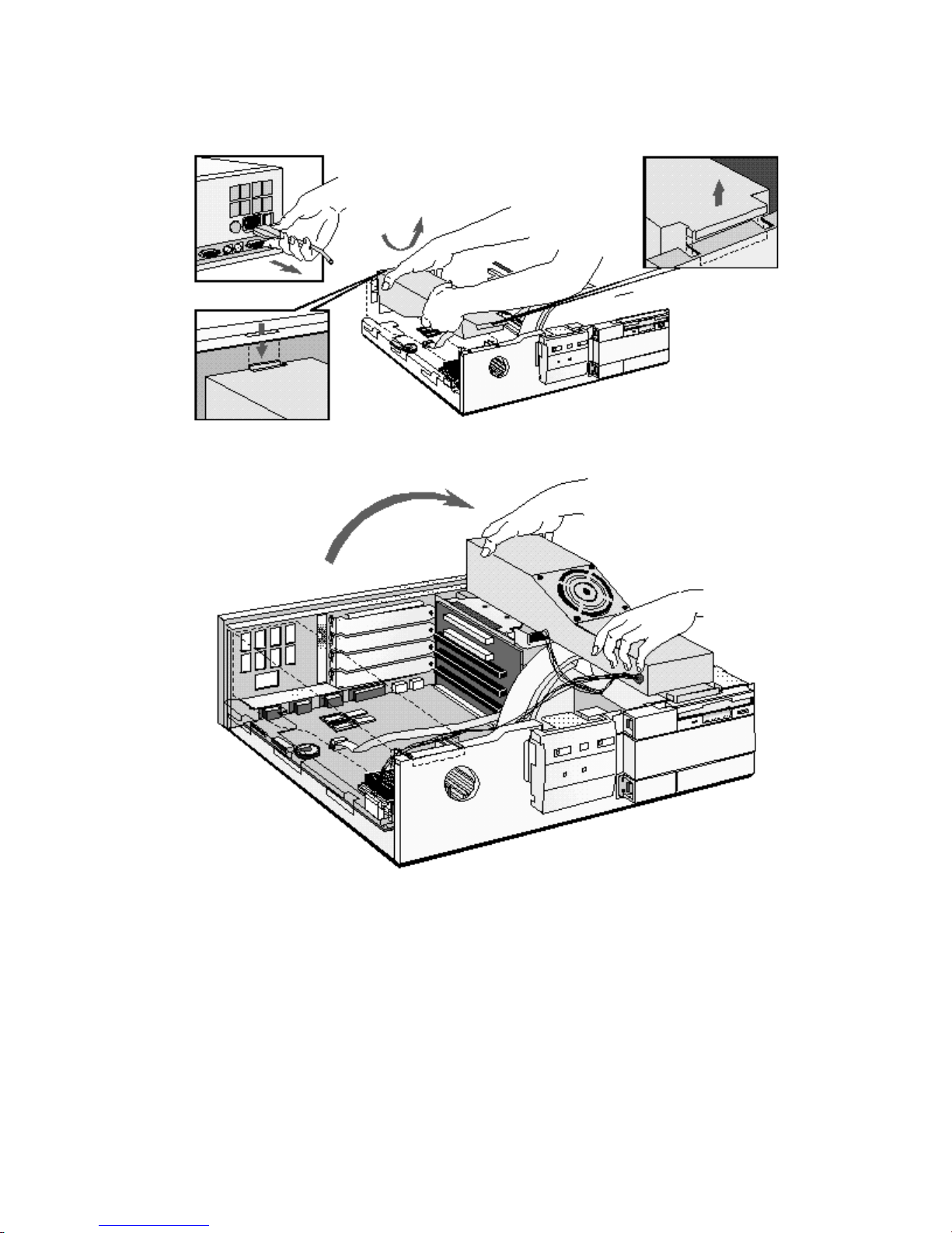
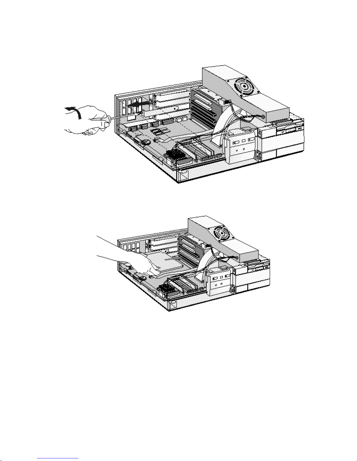
3 Lift the front of the power supply to disengage the hinge on the rear.
4 Lift the power supply clear and lay it upside down on the frame above the disk drives.
REPLACING THE POWER SUPPLY AFTER INSTALLING ACCESSORIES
1 Ensure that you have installed all your accessories in the PC.
2 Replace the power supply on the left-hand side of the PC, and ensure that the cables are
neatly routed around any accessory boards.
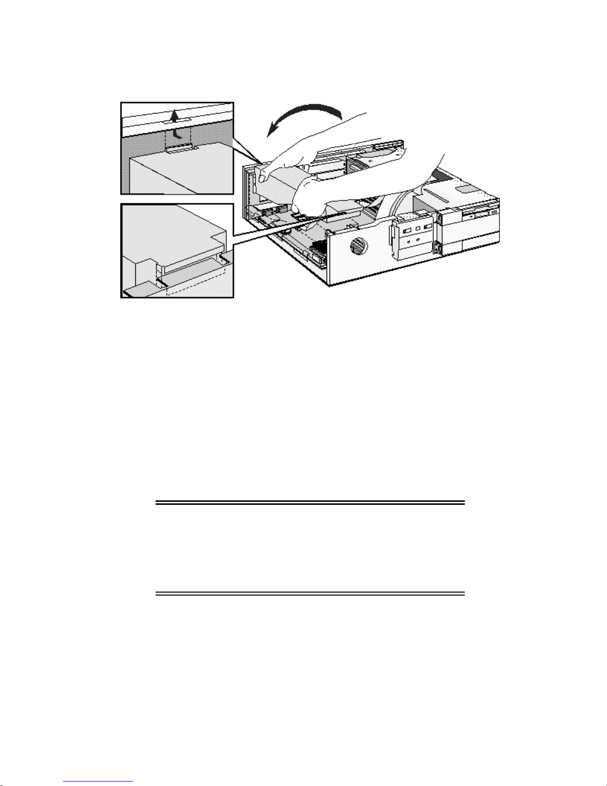
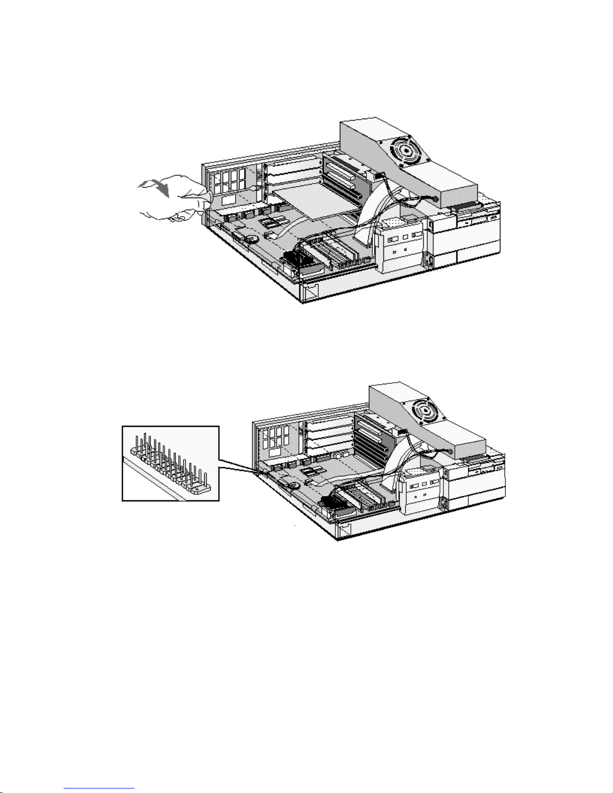
3 Raise the front of the power supply and engage the hinge on the rear.
4 Lower the front of the power supply into position so that it rests on the front panel.
INSTALLING MEMORY
MAIN MEMORY MODULES
Your PC is supplied with main memory. If you need more main memory to run your application
software, you can install up to a total of 128 MB.
Main memory is available in modules of 4 MB, 8 MB, 16 MB, or 32 MB. You must install
identical modules in pairs in each bank.
Banks A and B will take 4 MB, 8 MB, 16 MB or 32 MB modules. Use only 4 MB and 16 MB
modules in bank C, as 8 MB and 32 MB modules are not fully detected in this bank. 32 MB
modules are not available from HP. You can obtain 32 MB modules from your HP reseller.
CAUTION: Static electricity can damage electronic
components. Turn all equipment OFF. Don’t let
your clothes touch the accessory.To equalize the
static electricity, rest the accessory bag on top of
the power supply while you are removing the
accessory from the bag. Handle the accessory as
little as possible and with care.
To install a main memory module:
1 Disconnect the computer’s power supply cord and any connection to a
telecommunications network.
2 Remove the computer’s cover and power supply.
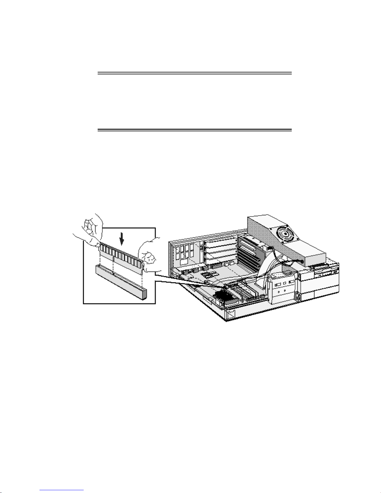
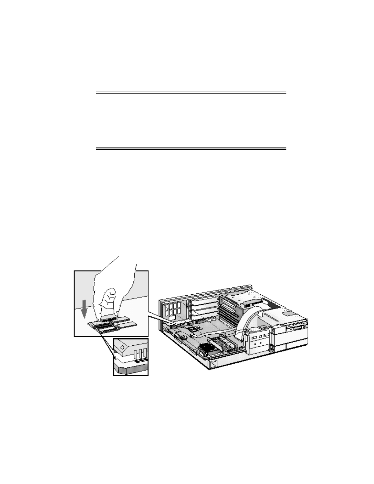
3 Align the main memory module directly over the socket. Slide the memory module into the
slot at 45°. Firmly press the memory module completely into the connector.
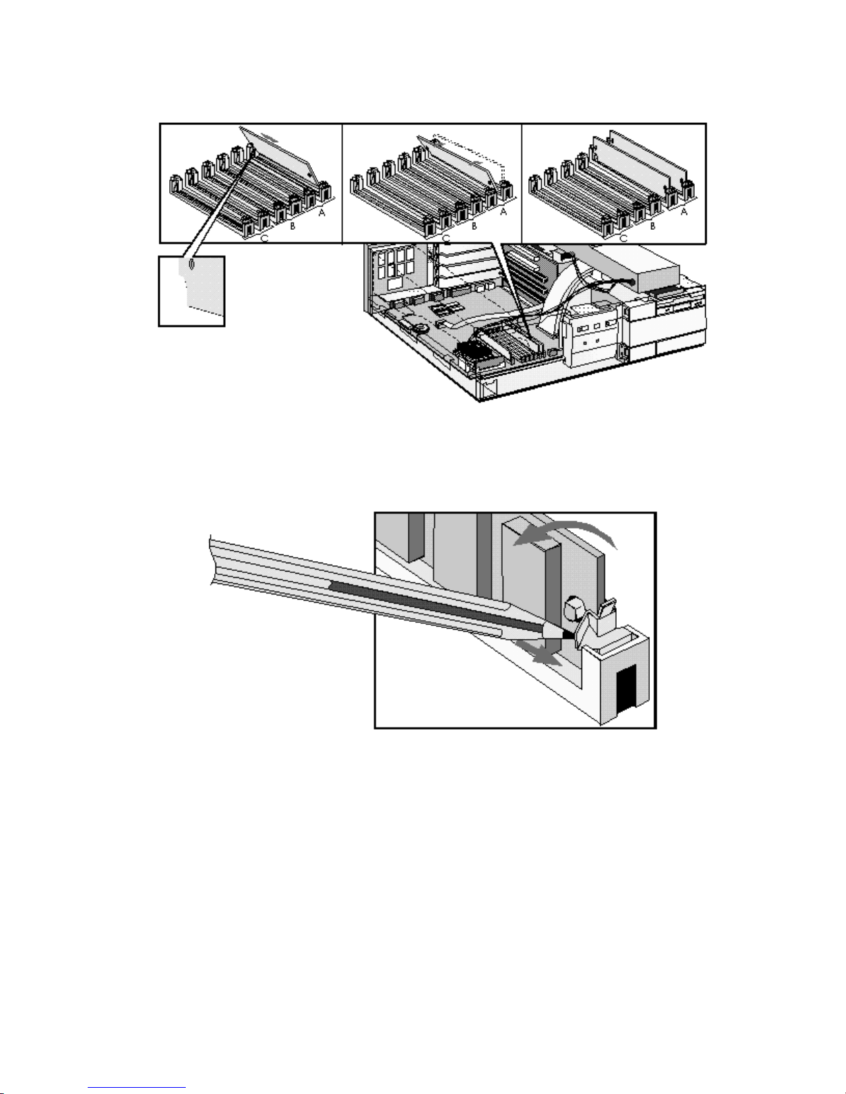
4 Pivot the memory module to the vertical position and click into place.
5 Repeat this procedure for each memory module you are installing.If you need to remove a
main memory module:
Release the retaining clip and pull the module forward and out of the socket
6 Install any other accessories before replacing the cover and power supply. Reconnect all
cables and power cords.
INSTALLING AN OPTIONAL CACHE MEMORY MODULE
You can install a 256 KB level 2 cache memory module. Order HP D3659A.
CAUTION: Static electricity can damage electronic
components. Turn all equipment OFF. Don’t let
your clothes touch the accessory.To equalize the
static electricity, rest the accessory bag on top of
the power supply while you are removing the
accessory from the bag. Handle the accessory as
little as possible and with care.
To install a cache memory module:
1 Disconnect the computer’s power supply cord and any connection to a
telecommunications network.
2 Remove the computer’s cover and power supply.
3 Align the cache memory module directly over the socket. Firmly press the memory
module completely into the connector.
4 Install any other accessories before replacing the cover and power supply. Reconnect all
cables and power cords.
INSTALLING A VIDEO MEMORY UPGRADE
Your PC is supplied with 1 MB of video memory on the system board. If you want better
performance, higher resolutions or more colors, you can install a pair of video memory
modules to increase your available video memory to 2 MB. Detailed information about
available video resolutions is given in chapter 5, Technical Information.
CAUTION: Static electricity can damage electronic
components. Turn all equipment OFF. Don’t let
your clothes touch the accessory.To equalize the
static electricity, rest the accessory bag on top of
the power supply while you are removing the
accessory from the bag. Handle the accessory as
little as possible and with care.
Installing Video Memory Modules
To install a pair of video memory modules on the system board, follow this procedure:
1 Disconnect the power supply cord and any connection to a telecommunications network.
2 Remove the computer’s cover and power supply. Refer to "Removing the Cover" and
"Moving and Replacing the Power Supply" earlier in this chapter.
3 Align the video memory module directly over the socket taking care to align the dot on the
Firmly
module with the corner notch on the socket as illustrated in the diagram.
memory module
in pairs.
completely
into the connector. Video memory modules must be installed
press the
4 Install any other accessories before replacing the cover and power supply. Reconnect all
cables and power cords.

After Installing a Video Memory Upgrade
1 Switch on the PC.
2 Select HP User Tools.
3 Click on the Video Mode button and follow the screen messages. You may be asked to
insert a diskette containing an appropriate video driver in drive A. For the latest available
version of a required driver, refer to the "HP BBS Library" in chapter 7.
INSTALLING ACCESSORY BOARDS
The PC has four accessory board slots:
• Slot 1 (the top slot) can be used for a 32-bit PCI board
• Slot 2 can be used for either a 32-bit PCI or a full-length 16-bit ISA board
• Slot 3 can be used for full-length 16-bit ISA boards
• Slot 4 (the bottom slot) can be used for short-length 16-bit ISA boards (16 cm/6.3-inch
maximum length).
CONFIGURING ACCESSORY BOARDS WITH PLUG AND PLAY
Plug and Play is an industry standard for automatically configuring your PC's hardware
resources and the accessory boards installed in it. Your PC has configurable support for Plug
and Play in the BIOS.
NOTE All PCI accessory boards are Plug and Play,
although not all ISA boards are. Check the accessory
board’s documentation if you are unsure.
When you start your PC after installing an accessory board, the Plug and Play BIOS
automatically detects which hardware resources (IRQs, DMAs, memory ranges, and I/O
addresses) are used by the system-based components.
CONFIGURING NON-PLUG AND PLAY ISA ACCESSORY BOARDS
If you install an ISA accessory board that is not Plug and Play you will need to configure the
board before your PC can use it.
Windows 3.11
For Windows 3.11 you must run the ISA Configuration Utility (ICU) program to declare the
resources used by the board:
1 Double-click on the Plug and Play group icon in the Windows Program Manager.
2 Double-click on the ICU Notes icon for up-to-date information about the Plug and Play
support for your PC.
3 Double-click on the ICU User Guide icon for detailed information about using the ICU.
4 Double-click on the ICU icon to launch the ISA Configuration Utility and configure system
resources for the accessory board.

The ICU is preloaded with configuration details for many non-Plug and Play accessory
boards. If your accessory board is not listed by the ICU, you have two options:
a Some non-Plug and Play accessory boards are supplied with a configuration file,
which can be used by the ICU to determine which resources are required by the board.
Insert the disk containing the configuration file when prompted by the ICU.
b If you do not have a configuration file for your accessory board, you will need to enter
the configuration details manually when prompted by the ICU. Refer to the
documentation supplied with your accessory board for information on the resources
required by the board.
Windows 95
For Windows 95 you will need to run the Add New Hardware wizard to configure the
accessory board. The settings selected by Windows 95 may be different from those
recommended by the board’s manufacturer. Should this be the case, it might be necessary to
alter the board’s jumpers. Refer to the documentation supplied with Windows 95 for further
details.
Other Operating Systems
For other operating systems, refer to the documentation supplied with the operating system for
details on how to configure non-Plug and Play accessory boards.
INSTALLING THE BOARD
1 Disconnect the computer’s power supply cord and any connection to a
telecommunications network.
2 Remove the computer’s cover and power supply.
3 Find a free slot. Some boards may have preferred locations and special installation
instructions detailed in their manuals.
4 Unscrew and remove the slot cover. Store it in a safe place. If the slot cover is tight,
loosen the screws on the adjacent slots.
5 Hold the board horizontally by its “top” edge. Slide it into the board guide of the chosen
slot. Do not bend the board.
6 Align the board’s connector with the slot’s socket and firmly press into the socket. Ensure
the board’s connector engages completely with the socket and does not touch components
on other boards.
7 Secure the board by replacing the slot cover screw. If you loosened the screws on
adjacent slots, tighten them.
8 If you install a VESA-standard video adapter board which uses the integrated video
graphics controller, connect the accessory board’s cable to the VESA pass-through
connector on the system board.
9 Install any other accessories before replacing the power supply and the cover. Reconnect
all cables and power cords.
 Loading...