

HP vc4820T, vc4825T Troubleshooting Manual

Troubleshooting Guide
HP vc4820T and vc4825T Thin Clients

© Copyright 2009 Hewlett-Packard
Development Company, L.P. The
information contained herein is subject to
change without notice.
Microsoft and Windows are trademarks of
Microsoft Corporation in the U.S. and other
countries.
The only warranties for HP products and
services are set forth in the express warranty
statements accompanying such products
and services. Nothing herein should be
construed as constituting an additional
warranty. HP shall not be liable for technical
or editorial errors or omissions contained
herein.
This document contains proprietary
information that is protected by copyright. No
part of this document may be photocopied,
reproduced, or translated to another
language without the prior written consent of
Hewlett-Packard Company.
Troubleshooting Guide
Thin Client
First Edition (May 2009)
Document Part Number: 575379-001

About This Book
WARNING! Text set off in this manner indicates that failure to follow directions could result in bodily
harm or loss of life.
CAUTION: Text set off in this manner indicates that failure to follow directions could result in damage
to equipment or loss of information.
NOTE: Text set off in this manner provides important supplemental information.
iii

iv About This Book

Table of contents
1 Product Description
Product features ................................................................................................................................... 1
Serial Number Location ....................................................................................................... 1
Front Panel Components ..................................................................................................... 2
Top Components ................................................................................................................. 3
Rear Panel Components ..................................................................................................... 4
Installing the Rubber Feet .................................................................................................... 4
Installing the Stand .............................................................................................................. 5
Removing the Stand ............................................................................................................ 6
Thin Client Management Solutions ...................................................................................................... 7
2 Hardware Changes
General Hardware Installation Sequence ............................................................................................. 8
Removing and Replacing the Secure USB Compartment Cover ......................................................... 9
Removing the Secure USB Compartment Cover ................................................................ 9
Replacing the Secure USB Compartment Cover ............................................................... 10
Removing and Replacing the Side Access Panel and Metal Side Cover ........................................... 11
Removing the Side Access Panel and Metal Side Cover .................................................. 11
Replacing the Metal Side Cover and Side Access Panel .................................................. 12
Installing Thin Client Options .............................................................................................................. 13
Installing the USB Device .................................................................................................. 13
Removing and Replacing the Battery ................................................................................ 14
External Drives .................................................................................................................. 15
Configuring Powered Serial Ports ...................................................................................................... 16
3 BIOS Settings, (F10) Utility
Using the BIOS Settings ..................................................................................................................... 25
Changing BIOS Settings from the repset utility ................................................................. 25
Changing BIOS Settings Using the F10 Utility ................................................................... 26
Setup Utility—System Information ..................................................................................... 27
Setup Utility—Standard CMOS Features .......................................................................... 27
Setup Utility—Advanced BIOS Features ........................................................................... 27
Setup Utility—Integrated Peripherals ................................................................................. 28
Setup Utility—Power Management Setup ......................................................................... 29
v

Setup Utility—Utility Task Actions ...................................................................................... 29
4 Diagnostics and Troubleshooting
LEDs ................................................................................................................................................... 30
Power-On Sequence .......................................................................................................................... 31
Power-On Diagnostic Tests ................................................................................................................ 31
Beep Codes ........................................................................................................................................ 32
POST Error Messages ....................................................................................................................... 32
Troubleshooting .................................................................................................................................. 33
Basic Troubleshooting ....................................................................................................... 33
Diskless (No-Flash) Unit Troubleshooting ......................................................................... 34
Troubleshooting Flowcharts ............................................................................................... 36
Initial Troubleshooting ....................................................................................... 36
Initial Troubleshooting Part 2 ............................................................................ 37
No Power, Part 1 ............................................................................................... 38
No Power, Part 2 ............................................................................................... 39
No Power, Part 3 ............................................................................................... 40
No Video, Part 1 ................................................................................................ 41
No Video, Part 2 ................................................................................................ 42
No Video, Part 3 ................................................................................................ 43
No Video, Part 4 ................................................................................................ 44
Error Messages ................................................................................................. 45
NO OS Loading ................................................................................................. 46
OS Not Loading from Flash ............................................................................... 47
Non-Functioning Pointing Device or Keyboard ................................................. 48
No Internal Network Connection ....................................................................... 49
No Audio ........................................................................................................... 50
No IP Address ................................................................................................... 51
Booting in Continuous Loop .............................................................................. 52
5 Restoring the Flash Image
System Requirements ........................................................................................................................ 53
Getting Started ................................................................................................................................... 53
Creating an ISO Image ....................................................................................................................... 54
Formatting a USB Flash Drive ............................................................................................................ 54
Unpacking the Image and Tools for Deployment ............................................................................... 55
Deploying with PXE ............................................................................................................................ 55
Appendix A Adding an Image Restore Tool
Appendix B Configuring a PXE Server
Prerequisites ...................................................................................................................................... 57
Installing Remote Installation Services (RIS PXE Server) ................................................................. 57
vi

Authorizing Remote Installation Services (RIS PXE Server) .............................................................. 57
Configuring Remote Installation Services .......................................................................................... 58
Set User Permissions on the Active Directory Server ........................................................................ 58
RIS Menu ........................................................................................................................................... 59
Creating Network Bootable Disk to Map Drives ................................................................................. 59
For More Information .......................................................................................................................... 59
Appendix C FTP Update
Server Requirements ......................................................................................................................... 60
DCHP Server ..................................................................................................................... 60
FTP Server ........................................................................................................................ 60
Description ......................................................................................................................................... 61
Host Settings ...................................................................................................................................... 61
Select Image to Update ...................................................................................................................... 62
Appendix D System BIOS
Restoring a Corrupt BIOS .................................................................................................................. 64
Updating a BIOS ................................................................................................................................ 65
Appendix E Electrostatic Discharge
Preventing Electrostatic Damage ....................................................................................................... 66
Grounding Methods ............................................................................................................................ 66
Appendix F Specifications
Index ................................................................................................................................................................... 69
vii

viii
1 Product Description
The following features are common to all HP thin clients:
●
no hard drives or diskette drives
●
5-minute hardware setup time
●
central deployment and management using HP Management Solutions
Operating systems
The vt4820T thin client models use the Windows Embedded Standard (WES) operating system.
The vt4825T Linux thin clients offer an extensible Linux image built upon Debian.
Product features
For more information, refer to the model-specific QuickSpecs at http://h18004.www1.hp.com/products/
quickspecs/QuickSpecs_Archives/QuickSpecs_Archives.html.
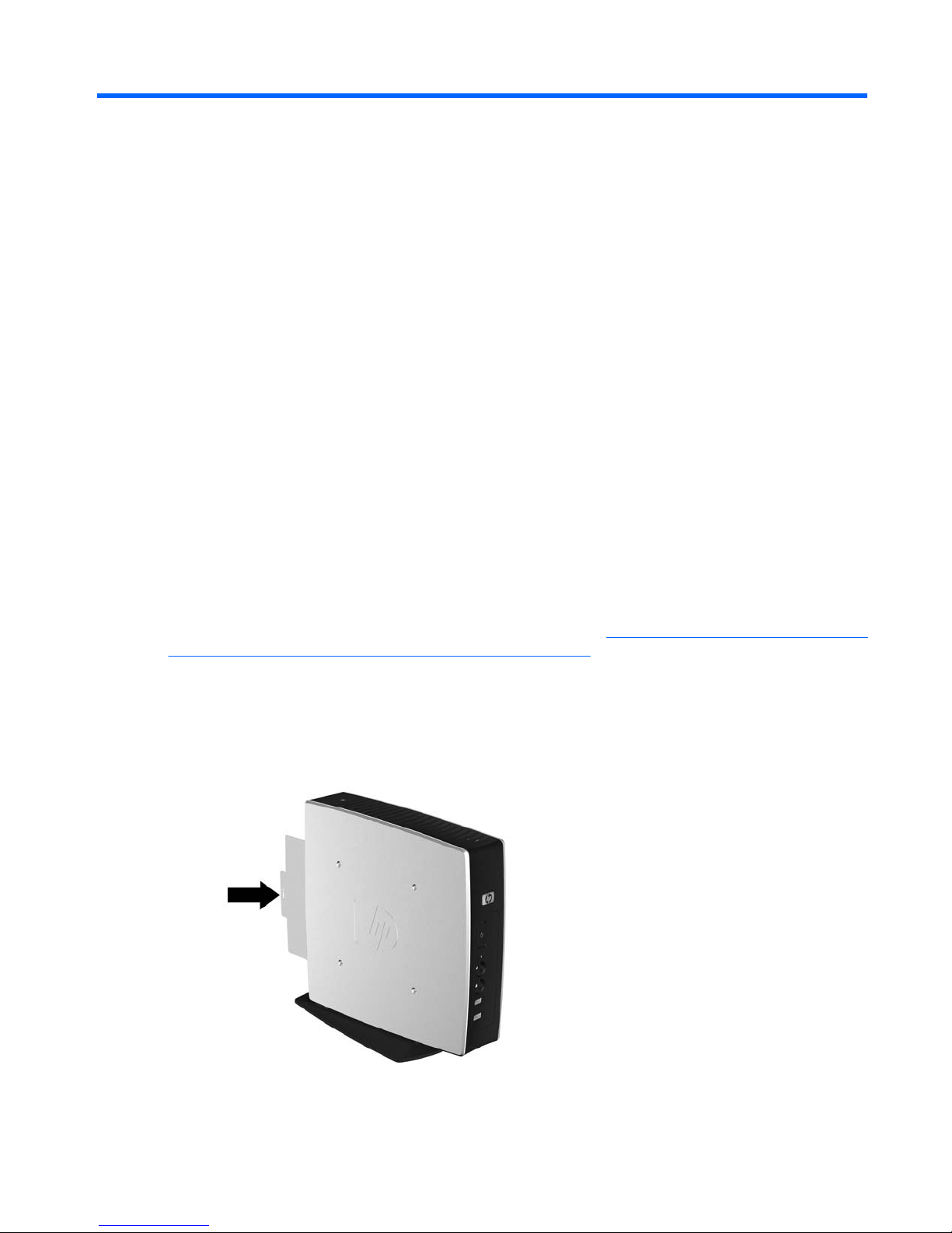
Serial Number Location
Every thin client includes a unique serial number located as shown in the following illustration. Have this
number available when contacting HP customer service for assistance.
Figure 1-1 Serial number location
Operating systems 1

Front Panel Components
For more information, http://www.hp.com and search for your specific thin client model to find the modelspecific QuickSpecs.
Figure 1-2 Front panel components
(1) Secure USB compartment (5) Power LED
(2) Power button (6) Line-out (headphone) audio connector
(3) Flash activity LED (7) Universal serial bus (USB) connectors (2)
(4) Line-in (microphone) connector
2 Chapter 1 Product Description
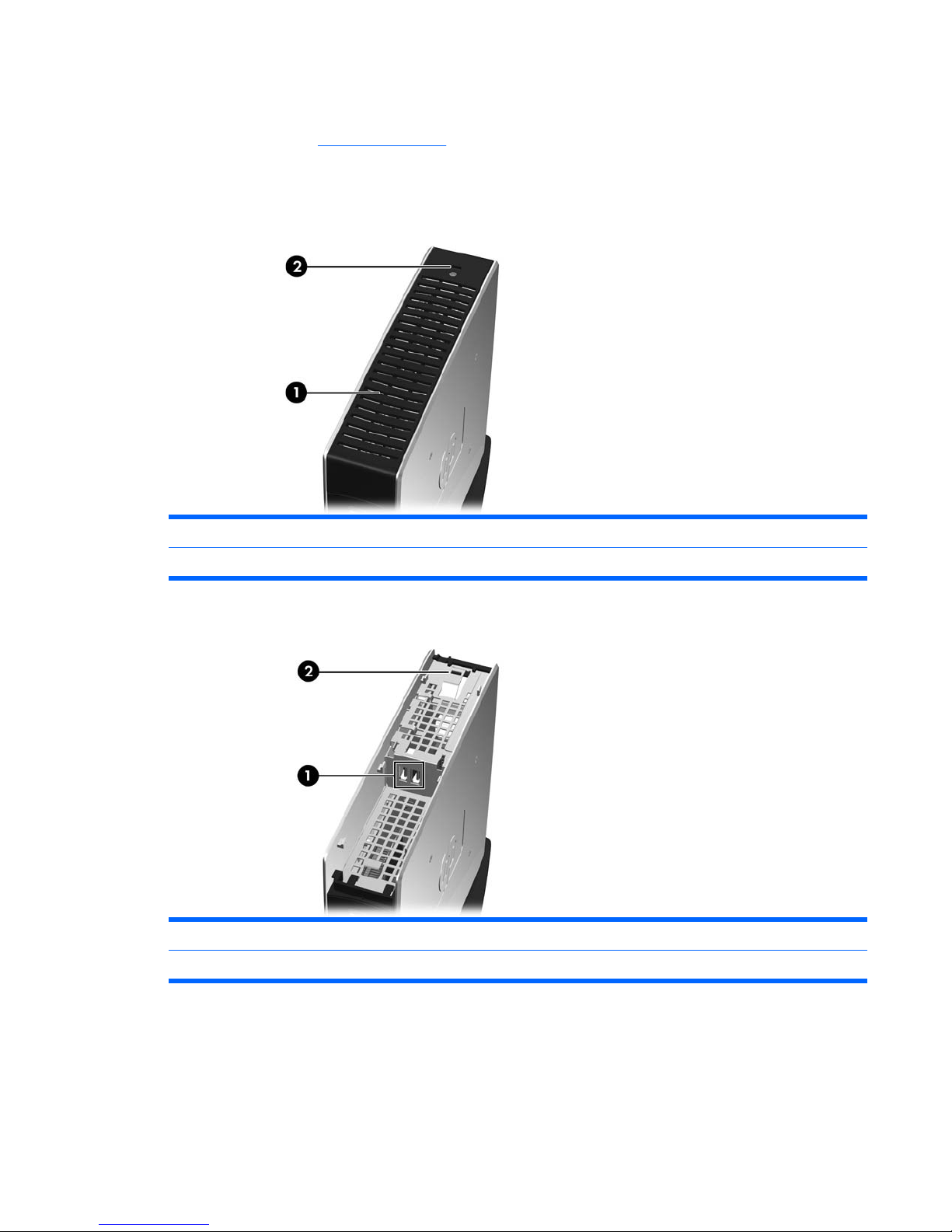
Top Components
For more information, http://www.hp.com and search for your specific thin client model to find the modelspecific QuickSpecs.
The secure USB compartment allows you to use two USB devices in a secured location.
Figure 1-3 Top components, external view
(1) Secure USB compartment
(2) Cable lock slot
Figure 1-4 Top components, internal view
(1) Secure USB compartment ports (2)
(2) Cable lock slot
Product features 3
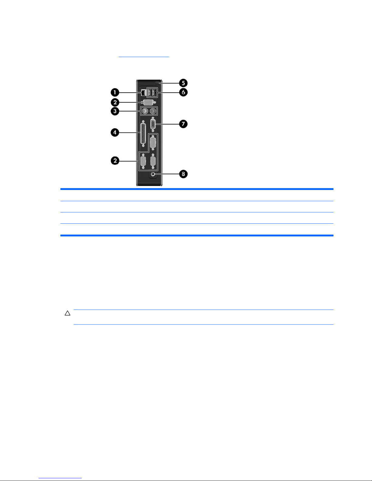
Rear Panel Components
For more information, http://www.hp.com and search for your specific thin client model to find the modelspecific QuickSpecs.
Figure 1-5 Rear panel components
(1) Ethernet RJ-45 connector (5) Secure cable routing slot
(2) Serial connectors (4) (6) Universal serial bus (USB) connectors (2)
(3) PS/2 connectors (2) (7) VGA connector
(4) Parallel connector (8) Power connector
Installing the Rubber Feet
You may want to use your thin client in a horizontal orientation. You can install rubber feet on the left
side of the unit to help keep the unit safely in place.
To install the rubber feet:
1. Locate the VESA (Video Electronics Standards Association) holes in the left side of the thin client.
CAUTION: If you use the thin client in a horizontal orientation without the rubber feet, it may slide
and result in equipment damage.
2. Remove the feet from their backing.
4 Chapter 1 Product Description
3. Align the feet with their holes and press them in securely.
Figure 1-6 Installing the rubber feet
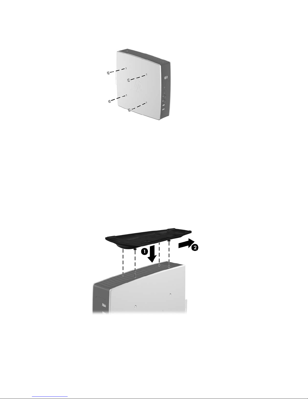
Installing the Stand
If you wish to use the thin client in a vertical orientation, you should install the stand for stability.
To install the stand:
1. Turn unit upside down.
2. Locate the slots on the bottom of the unit into which the tabs on the stand fit. Position the stand
with the wide part toward the front of the unit. Align the tabs on the widest part of the stand with
the slots approximately 7.6 cm (3 inches) from the front of the unit and the tabs on the narrower
part with the slots approximately 3.8 cm (1.5 inches) from the rear of the unit.
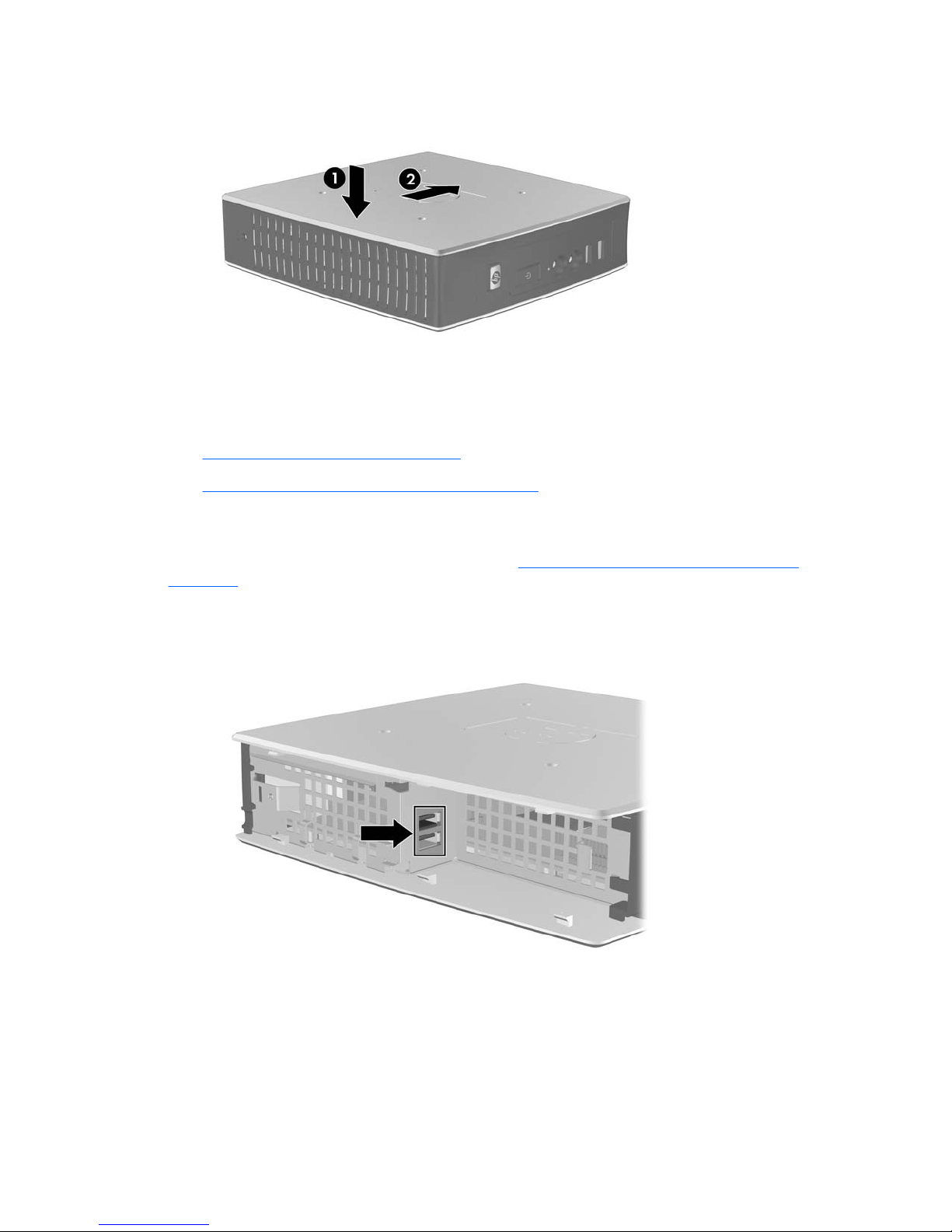
3. Insert the tabs into the slots (1) and slide the stand toward the back of the unit (2) until it locks into
place.
Figure 1-7 Installing the stand
Product features 5
Removing the Stand
To remove the stand:
1. Turn unit upside down.
2. Lift the tab (1), and then pull the stand up to remove it from the unit (2).
Figure 1-8 Removing the stand
6 Chapter 1 Product Description

Thin Client Management Solutions
HP has a comprehensive suite of management solutions to fit your needs. This allows you to choose
solutions that will work best in your environment.
HP ThinState Tools are a set of handy utilities that allow you to copy settings and software images from
one thin client to another using a USB drive key. HP ThinState tools complement other management
solutions and are included with HP thin client operating systems.
HP Device Manager is an enterprise-class thin client management software application that allows
customers to view their thin client assets remotely and to manipulate those thin clients to meet the
required business need. It is robust, yet easy to install and use. HP Device Manager lets you track,
configure, upgrade, clone, and manage thousands of individual devices from a centralized location. HP
Device Manager agents are included in most HP thin clients.
HP Client Automation is an industry-leading device management product, which is part of a bigger
Business Service Automation environment management solution. With HP Client Automation, you can
manage simple thin client deployments or highly complex IT environments that contain a combination
of thin clients, PCs, blades, servers and other common computer-based resources. HP Client
Automation agents work with all HP thin clients. For more information on HP Client Automation, please
visit the HP Web site at
http://www.hp.com and search for “Business Service Automation.”
HP continues to partner with Altiris to manage HP thin clients. Altiris Deployment Solution is a leading
tool for quick deployment and ongoing management of thin clients in your organization. With your thin
client hardware purchase, you are entitled to a complimentary, current release of Altiris Deployment
Solution. For additional information, refer to the Quick Setup and Getting Started Guide that came with
your thin client, and visit the Altiris Web site at
http://www.altiris.com/.
Thin Client Management Solutions 7

2 Hardware Changes
General Hardware Installation Sequence
To ensure the proper installation thin client hardware components:
1. Back up any data, if necessary.
2. If the thin client is powered on:
a. Turn off the computer properly through the operating system, then turn off any external
devices.
b. Disconnect the power cord from the power outlet and disconnect any external devices.
c. Disconnect any external devices or cables, such as a cable lock.
WARNING! To reduce the risk of personal injury from electrical shock and/or hot surfaces, be
sure to disconnect the power cord from the wall outlet and allow the internal system components
to cool before touching.
WARNING! To reduce the risk of electrical shock, fire, or damage to the equipment, do not plug
telecommunications or telephone connectors into the network interface controller (NIC)
receptacles.
CAUTION: Static electricity can damage the electronic components of the thin client or optional
equipment. Before beginning these procedures, ensure that you are discharged of static electricity
by briefly touching a grounded metal object. See
Electrostatic Discharge on page 66 for more
information.
3. Remove the secure USB compartment cover. See Removing and Replacing the Secure USB
Compartment Cover on page 9 for more information.
4. Remove the side access panel and metal side cover. See
Removing and Replacing the Side
Access Panel and Metal Side Cover on page 11 for more information.
5. Remove any hardware that you will replace.
6. Install or replace equipment. For removal and replacement procedures, see the following
sections:
●
Installing the USB Device on page 13
●
Removing and Replacing the Battery on page 14
NOTE: Option kits include more detailed installation instructions.
8 Chapter 2 Hardware Changes

7. Replace the side access panel and metal side cover. See Removing and Replacing the Side
Access Panel and Metal Side Cover on page 11.
8. Replace the secure USB compartment cover. See
Removing and Replacing the Secure USB
Compartment Cover on page 9.
9. Reconnect any external devices and power cords.
10. Turn on the monitor, the thin client, and any devices you want to test.
11. Load any necessary drivers.
NOTE: You can download select hardware drivers from HP. Go to http://www.hp.com and search
for your specific thin client model.
12. Reconfigure the thin client, if necessary.
Removing and Replacing the Secure USB Compartment
Cover
The secure USB compartment allows you to install two USB devices in a secure location inside the thin
client. The cable management feature allows you to install a USB mouse and a USB keyboard in this
compartment. See
Installing the USB Device on page 13 for more information. Along with providing
a hidden location, the secure USB compartment can be locked by the optional security cable lock.
CAUTION: The ambient temperature inside of the secure USB compartment can reach up to 55° C
(131° F) in worst case conditions. Make sure the specifications for any device you install in the
compartment indicate the device can tolerate a 55° C (131° F) ambient environment.
NOTE: In addition to following these instructions, follow the detailed instructions that accompany the
accessory you are installing.
Before beginning the installation process, review General Hardware Installation Sequence on page 8
for procedures you should follow before and after installing or replacing hardware.
Removing the Secure USB Compartment Cover
Use the following procedure to remove the secure USB compartment cover.
WARNING! Before removing the secure USB compartment cover, ensure that the thin client is turned
off and the power cord is disconnected from the electrical outlet.
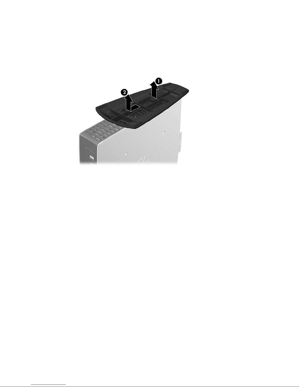
To remove the secure USB compartment cover:
1. Locate and remove the screw that secures the compartment cover (1) on the top of the thin client
toward the rear of the unit.
Removing and Replacing the Secure USB Compartment Cover 9
2. Push the compartment cover about .6 cm (1/4 inch) toward the front of the unit (2) and lift it off the
unit (3).
Figure 2-1 Removing the secure USB compartment cover
Replacing the Secure USB Compartment Cover
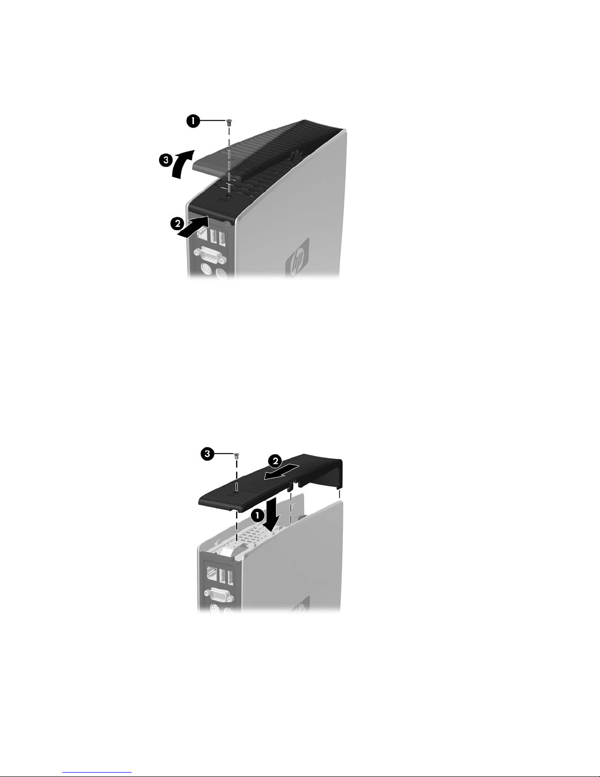
To replace the secure compartment cover:
1. Place the cover on top of the unit so it is offset about 0.6 cm (1/4 inch) toward the front of the unit,
allowing the tabs on the cover to align with the slots on the chassis (1).
2. Slide the cover toward the back of the unit until the cover is flush with the back panel of the
chassis (2).
3. Replace the screw (3).
Figure 2-2 Replacing the secure compartment cover
10 Chapter 2 Hardware Changes
Removing and Replacing the Side Access Panel and Metal
Side Cover
Removing the Side Access Panel and Metal Side Cover
WARNING! Before removing the side access panel, ensure that the thin client is turned off and the
power cord is disconnected from the electrical outlet.
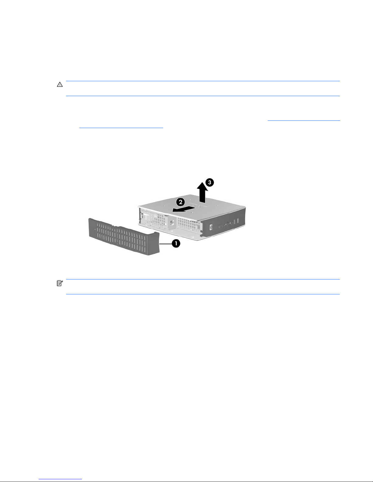
To remove the access panel:
1. Remove the secure compartment cover (1). For more information, see
Removing the Secure USB
Compartment Cover on page 9.
2. Lay the unit flat on a stable surface with the right side up and the left side down.
3. Slide the access panel about 3 mm (1/8 inch) toward the top of the unit (2), and then lift the access
panel up and off the unit (3).
Figure 2-3 Removing the side access panel
To remove the metal side cover:
NOTE: You must remove the metal side cover to access internal components such as the battery or
the memory.
1. Remove the four screws that secure the metal side cover to the chassis (1).
Removing and Replacing the Side Access Panel and Metal Side Cover 11
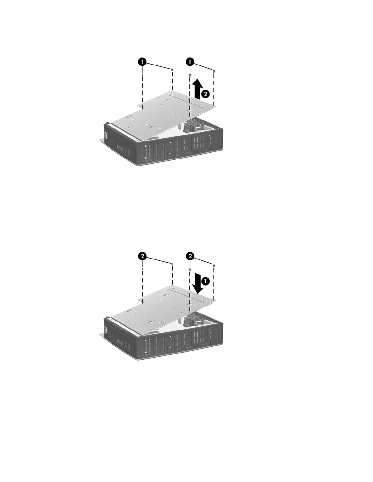
2. Lift the metal side cover, rear side first, off the unit (2).
Figure 2-4 Removing the metal side cover
Replacing the Metal Side Cover and Side Access Panel
To replace the metal side cover:
1. Slip the front edge of the metal side cover under the lip on the chassis and lower the cover until it
snaps into place (1).
2. Align the screw holes of the metal side cover with the chassis holes and insert and tighten the four
screws (2).
Figure 2-5 Replacing the metal side cover
To replace the access panel:
1. Align the tabs on the access panel with the slots in the metal side cover and place the access panel
on the side of the unit, offset about 3 mm (1/8 inch) toward the top of the unit (1).
12 Chapter 2 Hardware Changes
2. Slide the panel toward the bottom of the unit until the cover is flush with the bottom panel of the
chassis (2).
Installing Thin Client Options
Various options can be installed on the thin client:
●
Installing the USB Device on page 13
●
Removing and Replacing the Battery on page 14
Installing the USB Device
Before beginning the replacement process, review General Hardware Installation Sequence
on page 8 for procedures you should follow before and after installing or replacing hardware.
▲
Insert the USB device into the USB port in the secure USB compartment. See the following
illustration for the location of the ports in the secure USB compartment.
Figure 2-6 USB ports in the secure USB compartment
Installing Thin Client Options 13
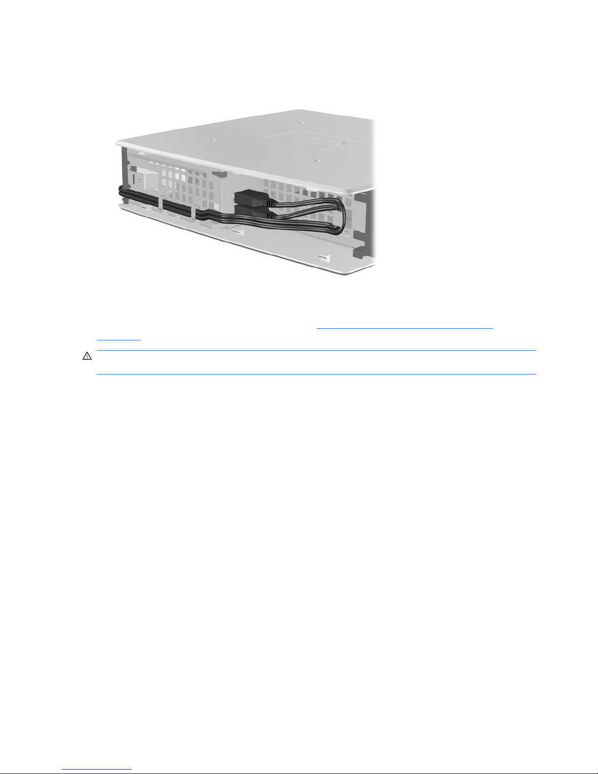
If you install a USB mouse and a USB keyboard in the secure USB compartment, route the cables
around and through the clips, then out the secure cable routing slot, as shown in the following illustration.
Figure 2-7 Using the secure cable routing slot
Removing and Replacing the Battery
Before beginning the replacement process, review General Hardware Installation Sequence
on page 8 for procedures you should follow before and after installing or replacing hardware.
WARNING! Before removing the side access panel, ensure that the thin client is turned off and the
power cord is disconnected from the electrical outlet.
To remove and replace the battery:
1. Locate the battery on the system board.
14 Chapter 2 Hardware Changes
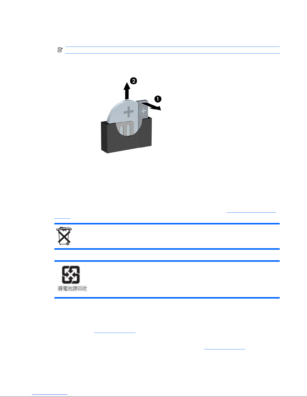
2. To release the battery from its holder, gently push the metal guard that extends above one edge
of the battery very slightly toward the rear of the unit, then lift the battery out (1).
NOTE: Be careful not to bend the metal guard.
Figure 2-8 Removing and replacing the internal battery
3. To insert the new battery, align the replacement battery with the positive side toward the + symbol
on the battery guard (facing the bottom of the thin client). Slide one edge of the battery into the slot
and push down until the guard snaps over the edge of the battery (2).
HP encourages customers to recycle used electronic hardware, HP original print cartridges, and
rechargeable batteries. For more information about recycling programs, go to
http://www.hp.com/go/
recycle.
Batteries, battery packs, and accumulators should not be disposed of together with the general household
waste. In order to forward them to recycling or proper disposal, please use the public collection system
or return them to HP, an authorized HP partner, or their agents.
The Taiwan EPA requires dry battery manufacturing or importing firms, in accordance with Article 15 or
the Waste Disposal Act, to indicate the recovery marks on the batteries used in sales, giveaways, or
promotions. Contact a qualified Taiwanese recycler for proper battery disposal.
External Drives
Various external USB drives are available as options for these thin clients. For more information about
these drives, visit
http://www.hp.com and search for your specific thin client model, or refer to the
instructions that accompany the option.
For more information about available options, visit the HP Web site
http://www.hp.com and search for
your specific thin client model.
Installing Thin Client Options 15
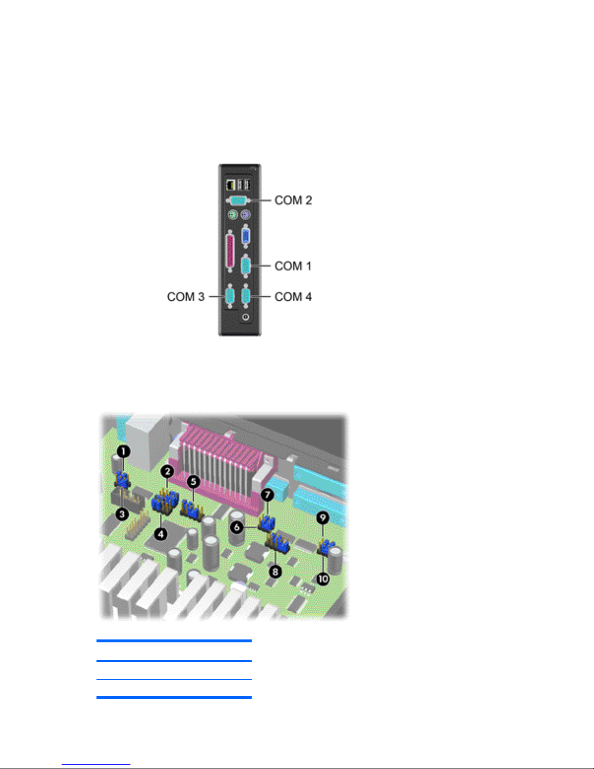
Configuring Powered Serial Ports
Three configurable, powered serial ports, COM 2, COM 3, and COM 4, are standard on the thin client.
COM 1 is a standard, non-powered serial port that cannot be configured. Some devices use a powered
serial port. If the serial port is configured as a powered port, devices that support a powered serial
interface do not require an external power source.
Figure 2-9 Powered Serial Ports
The serial port jumpers on the system board are located as shown in the following illustration:
Figure 2-10 Serial Port Jumper Locations on the System Board
Item Jumper
1 COM2 JP1
2COM2 JP4
16 Chapter 2 Hardware Changes
 Loading...