

Page 1

Service Reference Guide
HP Compaq vc4815 Thin Client
Document Part Number: 480421-001
January 2008
Page 2

© 2008 Hewlett-Packard Development Company, L.P.
HP, Hewlett Packard, and the Hewlett-Packard logo are trademarks of
Hewlett-Packard Company in the U.S. and other countries.
Compaq, and the Compaq logo are trademarks of Hewlett-Packard Development
Company, L.P. in the U.S. and other countries.
Microsoft, Windows, and Window s NT ar e U.S. registered trademarks of
Microsoft Corporation.
Transmeta, the Transmeta logo, Crusoe, the Crusoe logo, and combinations
thereof are trademarks of Transmeta Corporation in the U.S.A. and other
countries.
All other product names mentioned herein may be trademarks of their respective
companies.
The information contained herein is subject to change without notice. The only
warranties for HP products and services are set forth in the express limited
warranty statements accompanying such products and services. Nothing herein
should be construed as constituting an additional warranty. HP shall not be liable
for technical or editorial errors or omissions contained herein.
This document contains proprietary information that is protected by copyright. No
part of this document may be photocopied, reproduced, or translated to another
language without the prior written consent of Hewlett-Packard Company.
WARNING: Text set off in this manner indicates that failure to follow
directions could result in bodily harm or loss of life.
△
CAUTION: Text set off in this manner indicates that failure to follow
directions could result in damage to equipment or loss of information.
Service Reference Guide
HP Compaq vc4815 Series Thin Client
First Edition (Jan 2008)
Document Part Number: 480421-001
Page 3

Contents
Product Description
Network Firmware ..........................................................................................................1–1
HP Compaq Thin Client vc4815 Series ..........................................................................1–2
Serial Number Location ..................................................................................................1–6
Connecting USB Equipment ...........................................................................................1–6
Locating Additional Information ....................................................................................1–7
Spare Parts Lists
vc4815 Series Spare Parts List ........................................................................................2–1
HP vc4815 Series Setup (F10) Utility
Using HP vc4815 Series Setup (F10) Utility ..................................................................3–1
Diagnostics and Troubleshooting
Diagnostic Front Panel LEDs and Audible Codes ..........................................................4–1
Appendix A vc4815 Serial ports definition
Service Reference Guide www.hp.com iii
Page 4

Contents
Upload the Flash Image and system BIOS
Upload th e Flash image and BIOS ....................................................................................5–1
Thin Client vc4815 Specifications 6-1
iv
www.hp.com Service Reference Guide
Page 5

The HP Compaq Thin Client vc4815 Series are Redflag Linux-based
terminals that connect over a network to a server where all processing
and storage occurs. Because of the nature of the products,
troubleshooting is significantly simpler than on a standard PC and
previous thin clients.
The Graphical User Interface (GUI) is Chinese on all thin clients. If
you are using a foreign language keyboard, you will need to set
localized settings to perform the localization between a server-based
application and the device, but interaction with the unit itself remains in
Chinese.
Network Firmware
PXE (Pre-boot Execution Environment) is supported on all HP
Compaq Thin Client vc4815 Series products.
PXE allows a client to boot from a server on a network prior to
booting the embedded Operating System (OS) from the local Flash
module. As long as the system is connected to AC power, the Network
Interface Controller (NIC) on a PXE-enabled client remains powered
even when the system is turned off. This allows a network
administrator to remotely wake up the unit and perform various
management tasks, including loading the operating system and other
software onto the device from a server over the network.
1
Product Description
Service Reference Guide www.hp.com 1-1
Page 6
Product Description
HP Compaq Thin Client vc4815 Series
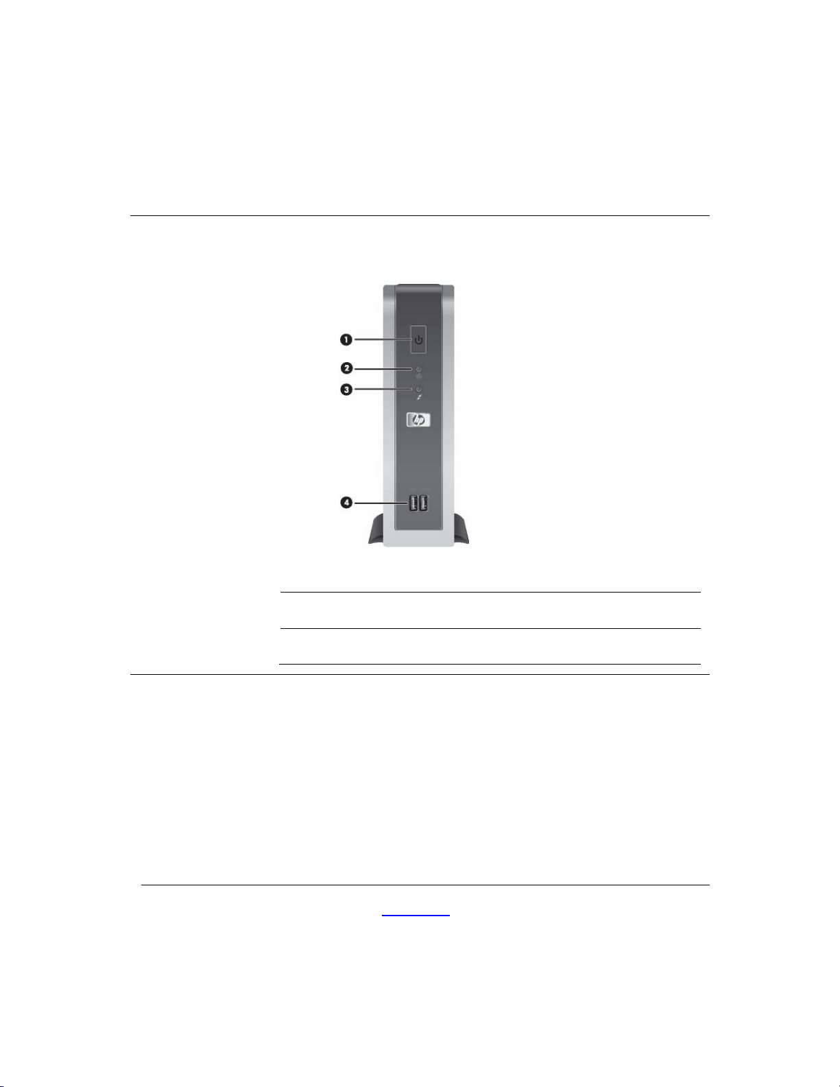
Front view - vc4815
Power button
1
Power LED
2
Service Reference Guide www.hp.com 1-2
Flash activity LED
3
USB ports (2)
4
Page 7
Product Description Product Description
HP Compaq Thin Client vc4815 Series
△
type as recommended by the manufacturer.
Service Reference Guide
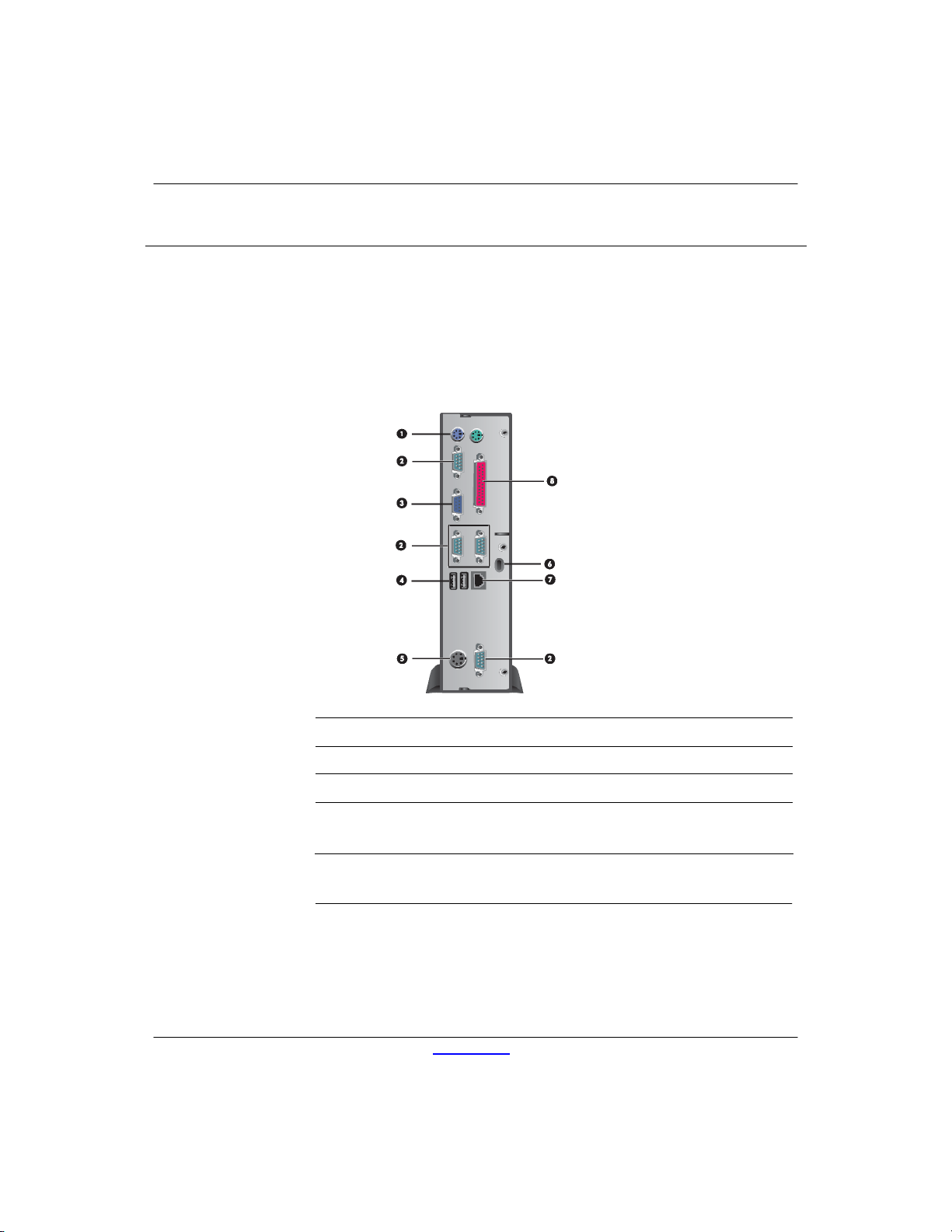
Rear View of the vc4815
PS/2 connectors (2)
1
Serial connectors (4)
2
Monitor connector
3
Universal Serial Bus (USB)
4
connectors (2)
CAUTION: The vc4815 Series power cord connector is for use only
with the supplied powe r adap tor . Re place only with the same or equival en t
www.hp.com 1-3
Power connector
5
Lock Slot
6
Ethernet RJ-45 connector
7
Parallel connector
8
Page 8
Product Description
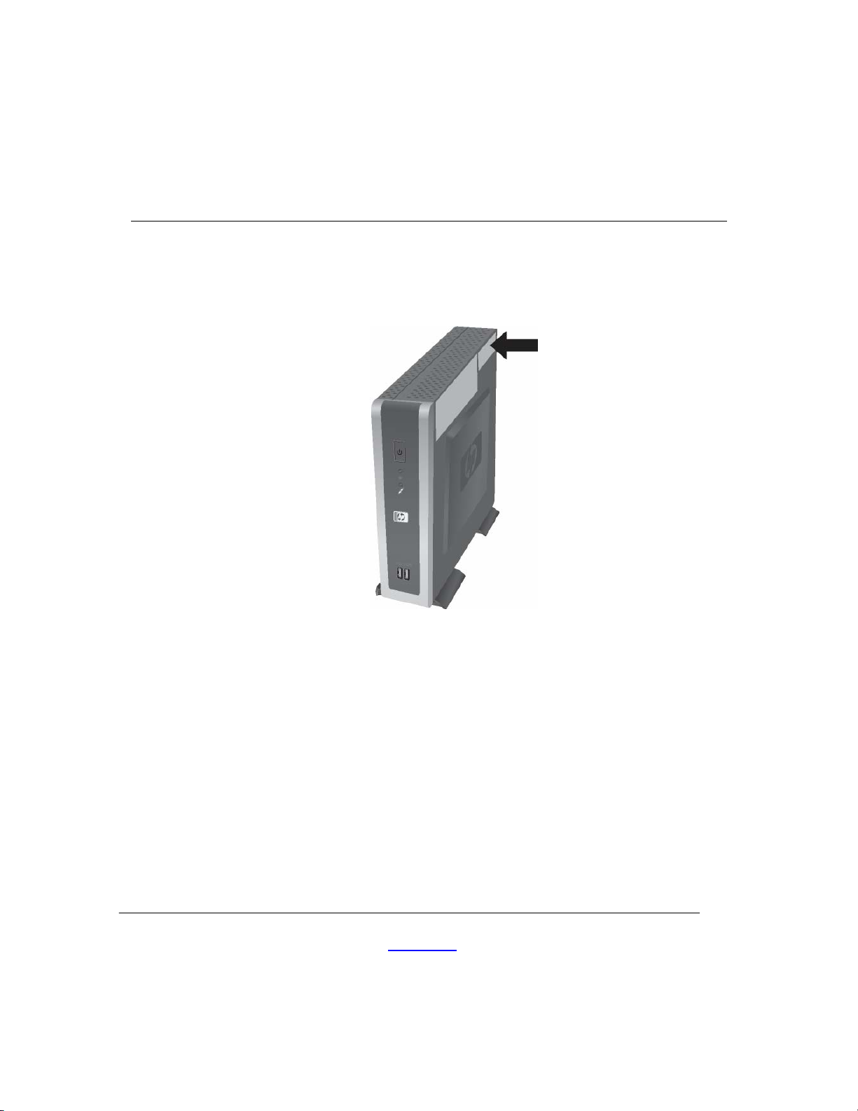
Serial Number Location
The serial number is displayed on the side of the unit.
Connecting USB Equipment
USB mouse devices and keyboards do not require special drivers and
are considered to be plug and play peripherals. Certain USB devices
such as printers and modems, however, may require special drivers.
For information on requirements for special drivers, refer to the
documentation that is included with the USB device.
Service Reference Guide
www.hp.com 1-4
Page 9

Locating Additional Information
The following documentation is available to support these products:
Quick Setup
Hardware Reference Guide
Redflag Linux User manual
Customer and Service Notifications, Bulletins and Advisories
Quickspecs
✎ Documentation, white papers, and drivers are subject to change. For the
latest HP thin client documentation, visit the following Web site:
http: //h18004.www1.hp.com/products/thinclients/software.html
Product Description
Service Reference Guide
www.hp.com 1-5
Page 10

Spare Parts Lists
vc4815 Series Spare Parts List
The spare parts tables that follow provide a listing of the spare parts
available for the Thin Client vc4815 Series.
vc4815 Series Spare Parts Table
Description Spare Part
SPS-Base, vc4815 512F/512R Linux 458813-001
SPS-Base, vc4815 1GBF/512R Linux 458814-001
SPS-Base, vc4815 2GBF/512R Linux 458815-001
SPS-KYBD USB, Basic, Vista-PRC 435382-AA1
SPS-MOUSE,OPTICAL CARBONITE 390938-001
For a full list of supported and leveraged Hewlett-Packard and third
party options, go to:
http://h18004.www1.hp.com/products/thinclients/software.html
2
Number
Service Reference Guide www.hp.com 1-6
Page 11

HP vc4815 Series Setup
(F10) Utility
Using HP vc4815 Series Setup (F10) Utility
The Setup utility can be accessed only by turning the co mputer on or
restarting the system. To access the Setup Utility menu, complete the
following steps:
1. Turn on or restart the computer.
2. When the F10 <BIOS Setup> message displays in the task bar
at the bottom of the screen, press the
✎ If you do not press the F10 key while the message is displayed, you
must restart the computer again to access the utility. When the F10
Post Screen display is set to zero seconds, it may be necessary to
press and hold
3. A choice of five menu headings and five task headings appears in
the Setup Utility menu:
Menu Headings: System Information, Standard CMOS Features,
Advanced BIOS Features, Integrated Peripherals, and Power
Management Setup.
Task Headings: Load Defaults Setting, Set Supervisor
Password, Set User Password, Save Setting and Exit, and
Exit without Saving.
F10 on the keyboard, then power on the computer.
F10 key.
3
Service Reference Guide www.hp. com 3-1
Page 12

HP vc4815 Series Setup (F10) Utility
4. Use the arrow (up and down, or left and right) keys to select the
appropriate heading, then press the
Setup Utility menu, press the
5. To apply and save changes, select Save Setting and Exit Setup.
✎ If you have made changes that you do not want applied, select
✎To reset to factory settings, select Load Defaults Setting. This
option will restore the original factory system defaults.
CAUTION: Do NOT turn the computer power OFF while the ROM
△
is saving your F10 Setup changes because the CMOS could become
corrupted. It is safe to turn off power to the computer ONLY after you exit
the F10 Setup screen.
vc4815 Series Setup Utility
Heading Option Description
System
Information
Enter key. To return to the
Esc key.
Exit without Saving.
Lists:
- Product name
- BIOS Version
- BIOS Release Date
- System Chipset Type
- Processor type
- Processor Speed
- CPU ID
- DDR Memory Size
- UUID (Universal Unique ID)
- Chassis Serial Number
- Set Asset TAG number
- Asset Tag Number
Service Reference Guide
✎ Support for specific Setup o p tions may vary depending on y our
hardware configuration.
www.hp.com 3-2
Page 13

HP vc4815 Series Setup (F10) Utility
vc4815 Series Setup Utility (Continued)
Heading Option Description
Standard
CMOS
Features
Advanced
BIOS
Features
System Date Allows you to set the date
System Time Allows you to set the time.
IDE channel 0
Indicates ATA Flash settings
Master
IDE Channel 1
Master
Halt on Allows you to select system response
when POST Error has been detected.
Quick Power
On Self Test
Hard Disk Boot
Priority
First Boot
Device
Second Boot
Device
Third Boot
Device
Allows the system to skip certain tests
while booting so the unit has a faster
boot.
Allows Setting of ATA Flash Disk or
Bootable Add-in Cards Boot Priority
Select Boot Device Priority. The default is
set to Hard Disk.
Select Boot Device Priority
Select Boot Device Priority
Service Reference Guide
Boot other
Device
Bootup
NumLock
Status
Security
Option
Enable/disable boot from other device
Select Power On state for NumLock.
Select whether the Password is required
every time the system boots or only when
you enter Setup.
✎Support for specific Setup options may vary depending on your
hardware configuration.
www.hp.com 3-3
Page 14

HP vc4815 Series Setup (F10) Utility
vc4815 Series Setup Utility (Continued)
Heading Option Description
Integrated
Peripherals
USB Controller Enable/disable USB controller
Power
Management Setup
Integrated
Audio
Network
Controller
Onboard Serial
port 1
Onboard Serial
port 2
Onboard Serial
port 3
Onboard Serial
port 4
Onboard Parallel
Port
Parallel Mode Select parallel port transfer mode
ECP Mode
Use DMA
Restore On
AC/Power Loss
Resume on PME
Wake on Ring
Enable/disable onboard AC97 audio
controller
Enable/disable onboard LAN de vice
Select serial port base IO port address
and IRQ
Select parallel port base IO port address
and IRQ
Select DMA channel if parallel is
Operated in ECP mode.
Allows you to set off, On, Last State
Enable/disable system wakeup capability
for onboard LAN device and PCI Card
Enable/disable Wake on Ring
Service Reference Guide
Load Defaults
Setting
Resume On
Alarm
Select Yes or No (Y/N)
Enable/disable Resume On Alarm, allow to
set Date(of month), Resume
Time(hh:mm:ss)
✎ Support for specific Setup o p tions may vary depending on y our
hardware configuration.
www.hp.com 3-4
Page 15

HP vc4815 Series Setup (F10) Utility
Heading Option Description
HP vc4815 Series Setup (F10) Utility
vc4815 Series Setup Utility
Heading Option Description
Set
Supervisor
Password
Allows you to set and enable the
administrative password.
✎ If the administrative password is set, it
(Continued)
is required to change the Setup options,
flash the ROM, and make changes to
certain plug and play settings under
Windows
Set User
Password
Allows you to set and enable the user
password.
✎ When the user password is set,
it prevents unauthorized access to the
user’s setup. User password provides
read-only access to Setup options.
Save
Setting
and Exit
Exit
without
Saving
Saves data to CMOS
Exits the Setup Utility without saving any
changes.
✎
Support for specific Setup o ptions may vary depending on your
hardware configuration.
Service Reference Guide
www.hp.com 3 -5
Page 16

4 Diagnostics and Troubleshooting
POST Diagnostic Front Panel LEDs and Audible
Codes
Diagnostic Front Panel LEDs and Audible Codes
Possible Cause
This section covers the front panel LED codes as well as the audible codes that may occur
before or during POST that do not necessarily have an error code or text message
associated with them.
✎If you see flashing LEDs on a PS/2 keyboard look for flashing LEDs on the front
panel of the computer and refer to the following table to determine the front panel
LED codes.
✎Recommended actions in the following table are listed in the order in which they
should be performed.
Beeps &
LED blink
Activity Recommended Action
Computer on. None Green Power LED On. None
Pre-video memory 5
Service Reference Guide www.hp.com 4 -1
Green Power LED flashes
five
times, once every second,
followed by a two second
pause.
Beeps stop after fifth
iteration but LEDs continue
until problem is solved.
CAUTION: To avoid damage to the DIMMs or the system
board, you must unplug the computer power cord before
attempting to reseat, install, or remove a DIMM module.
1. Reseat DIMMs.
2. Replace DIMMs one at a time
to isolate the faulty module.
3. Replace third-Party memory with HP memory.
4.Replace the system board
Page 17

Diagnostic Front Panel LEDs and Audible Codes
Possibl
e Cause
System
unable
to power
on.
Beeps
Activity Recommended Action
& LED
blink
None System does
not power on
and LEDs are
not flashing.
Press and hold the power button for less than 4
seconds.
If the hard drive LED turns green, the power butto n
is working correctly. Then, Replace th e system
board.
OR
If the hard drive LED does not turn on green
then:
1. Check that the unit is plugged into a working AC
outlet.
2. Check that both power supply cables are proper ly
connected
to the system board.
3. Check to see if the 5V_aux light on the system
board is turned on. If it is turned on, then replace
the power button
harness. If the problem persists, replace the system
board.
4. If the 5V_aux light on the system board is not
turned on, remove the expansion cards one a t a
time until the 5V_aux light on the system board
turns on. It the problem persists, replace the power
adapter.
✎
* Replacing the system board should ONLY be the last resort.
** Replacing the power supply should ONLY be the last resort.
Service Reference Guide www.hp.com 4-2
Page 18

5
Reload Flash Image and BIOS
System Requirements
To create a recovery device for the purpose of reflashing or restoring
the software image on the ROM, you will need the following:
One or more HP Compaq vc4815 Series Thin Clients
USB flash device 512MB Compatible USB flash devices (drive
keys) are available from
www.diskonkey.com.
This restore method will not work with all USB flash devices.
USB flash devices with multiple partitions generally do not
support this restore method. The range of USB flash devices
available on the market is constantly changing. Not all USB flash
devices (drive keys) have been tested with the HP Compaq Thin
Client Imaging Tool.
USB CD-ROM drive for thin client (if using the ISO Image
option)
Before using the utility, you must download the appropriate image
http://www.hp.com/products/thinclientsoftware.
from
Service Reference Guide www.hp.com 5-14
Page 19

Reload image and system BIOS
Hainan Image Reloading
1, Download the Image file *.gho from web.
2, Make a DOS Bootable USB flash drive(>=512M). Copy the image file and
ghost.exe (ver11.0.1) to the USB flash drive.
3, Boot from the USB device. Run ghost.exe.
System BIOS Update
1. Download the SoftPaq .EXE file to a directory on your hard drive.
2. Execute the downloaded file and follow the on-screen instructions.
3. Choose one of the following three options when presented:
- Create BIOS Flash Diskette,
- Create BIOS Flash DriveKey
4, Boot Unit with the diskette or Flash DriveKey made last in step.
Do not power off or reset the unit during flash BIOS process.
Service Reference Guide
www.hp.com 5-2
Page 20

GV665PA#AB2 vc4815
vc4815 LNX 512F/512R
PRC
GV666PA#AB2
vc4815 LNX 1GBF/512R
PRC
GV667PA#AB2
vc4815 LNX 2GBF/512R
PRC
6
Thin Client vc4815 Specifications
Specifications - vc4815 Series
Item Description
Processor VIA C7 1GHz
Chipset VIA CN700 + 8237R
Operating System Redflag Linux (Chinese version only)
Flash Memory Apacer ADMII series 44PIN 180 degree DOM,
512 MB, 1GB, 2GB
2 slots
Memory HP 512 MB DDR2 533 SDRAM or DDR2 667 SDRAM downgraded
to 533 One slot
(NOTE: 16 MB of system RAM is reserved for graphics memory)
Graphics VIA S3 Unichromo Pro Graphic integrated
PCI Expansion No
Browser Firefox Explorer with java support
Client Management
Software
Terminal Personalities
Standard
Power adapter 65W
Keyboard USB or PS/2 (both supported)
Mouse USB or PS/2 (both supported)
Foot stand Yes
Altiris Deployment Solution (client agen t)
Yes, terminal emulation tool under Linux
Keyboard included with every thin client. Type of included
keyboard (USB or PS/2) varies by region
Keyboard included with every thin client. Type of included
keyboard (USB or PS/2) varies by region
Service Reference Guide
www.hp.com 6-1
Page 21

Thin Client vc4815 Specifications
Specifications - vc4815 Series
Item Description
Flash Memory 512 MB , 1GB, 2GB, Apacer ADMII series 44PIN 180 degree DOM Memory
System Memory 512 MB DDR-II SDRAM
NOTE: 16 MB of system RAM is reserved for graphics memory
Graphics
VIA S3 Unichromo Pro VGA integrated
Mode Refresh Rates Color Depth
800 x 600 60-120 Hz 16/32 bit
1024 x 768 60-100 Hz 16/32 bit
1152 X 864 60-85 Hz 16/24 bit
1280 x 1024 60-85 Hz 16/32 bit
1600 x 1200 60-85 Hz 16/24 bit
640x480
800x600
1024x768
1280x720
1280x768
1280x800
1280x1024
1360x768
1366x768
1440x900
1600x1200
1920x 1440
1440x 900
1680 x 1050
1920x1200
Input/Output/
Peripheral Support
Keyboard HP USB or PS2 Standard Keyboard
Mouse HP USB or PS2 two-button scroll mouse
60-160 Hz
60-120 Hz
60-100 Hz
60-85 Hz
60-85 Hz
60-85 Hz
60-85 Hz
60-85 Hz
60-85 Hz
60-85 Hz
60-85 Hz
60-75Hz
60 Hz
60 Hz
60 Hz
Printer Local and/or network printers (RDP, ICA, LPD) as per the printer
support statement
Video VIA S3 Unichromo Pro VGA integrated
Security One security lock slot (cable lock sold separately)
Terminal Server
Protocols
Integrated rdesktop RDP client (1.4.1) and Citrix ICA 10.0 client support. Terminal
Emulation software re-development for finance
Networking 10/100 BaseT Fast Ethernet, twisted pair (RJ-45)
TCP/IP with DNS and DHCP, Direct Connection through RS-232
Point-to-Point Protocol (PPP),PPPoE, PPTP, EAP, PEAP, Wake on LAN (WOL), PXE
Service Reference Guide
www.hp.com 6-2
Page 22

I/O ports and
Four USB ports (two in front, two in rear), 4 serial, one parallel, one RJ-45, two PS/2
connectors
Resident Operating
Redflag Linux
System
Session Allocation
Managers/Session
Brokers
Server OS
Compatibility/
Support
HP PC Session Allocation Manager Software for the Consolidated Client Infrastructure,
Citrix Desktop Broker for Virtual Desktop Infrastructure
Open source Terminal Emulation:
CT100, VT100, VT220, VT382, Xenix, ANSI
Terminal service:
Microsoft® Windows® NT 4.0 Server, Windows NT 4.0 Terminal Server Edition, Windows
2000/2003 Server families, Windows 2000/2003 Server Terminal Services, Windows 2000
Advanced Server, Windows 2000 Advance Server Terminal Services
Citrix:
Citrix Presentation Server 4.0, including the Desktop Broker feature, Citrix Metaframe
Presentation Server 3.0, Citrix Metaframe XP Presentation Server, Citrix M etaframe 1.x,
and Linux Server versions
Software Included HP Connection Administrator, Firefox Browser, Citrix ICA, rdesktop RDP client (for RDP),
Altiris Deployment Solution 6. 8 (client agent) preinstalled.
Terminal Emulation software re-development for finance system.
Printing: support screen print, transparent print , 4 auxiliary serial ports terminal
emulation & Graphic display
Flash Player suppor t, txtpad , control panel support
Chinese input: Pinyin, Wu bi, Qu wei
Note: Altiris Deployment Solution (management console) available as free download
from Altiris at:
www.altiris.com/hptc
Other software available as add-ons (see
www.hp.com/support for latest list of
available add-ons)
Languages Chinese only
Page 23

Dimensions H x W x D
n
p
n
s
(approximate)
Weight (approximate) Without stand 1.9 kg
Environmental
Regulatory
Compliance
Emulations
Without stand 235 x 60 x 195 mm
Temperature range on 50° to 104° F (10° to 40° C)
Temperature range off -22° to 140° F (-30° to 60° C)
Humidity 20% to 80% condensing
10% to 95% non-condensing
1
Power
Agency CCC and CB
Environmental CECP (to be applied after product launch), ROHS complia
ESD 4KV for Direct, and 8KV for discharge
Three-year limited hardware warranty Warranty
NOTE: Certain restrictions apply. Consult the HP Customer Support Center for detail
Emulation Terminal ID
ANSI
CT100
VT100 VT100, VT220, VT382
Xenix
Worldwide auto-sensing 100-240 V AC, 50-60 Hz, energy-savi
automatic power-down, surge-tolerant, 65-watt power sup
Service Reference Guide www.hp.com 6-4
Page 24

义
Appendix A
HP Compaq vc4815 系列串口定义用户指南
HP Compaq vc4815终端默认具有4个串口,分别为串口一、串口二,串口三、
串口四。
定
引脚
1脚
主口
(串口1)
DCD/ +5V +5V / DCD +5V / DCD +5V / DCD
辅口1
(串口2)
辅口2
(串口3)
(TTL)
辅口3
(串口4)
2脚
3脚
4脚
5脚
6脚
7脚
8脚
9脚
RXD RXD RXD/TXD RXD
TXD TXD TXD/RXD TXD
DTR/ +12V DTR/+5V /+12V NC/DTR DTR/+5V /+12V
GND GND GND GND
DSR DSR NC/DSR DSR
RTS/+12V RTS/+12V NC/RTS RTS/+12V
CTS/RXD
(TTL)
RI/TXD
(TTL)
CTS RXD/TXD(TTL) CTS
RI TXD/RXD(TTL) RI
Page 25

义
HP Compaq vc4815终端默认出厂设置
定
主口
引脚
1脚
(串口1)
DCD DCD DCD DCD
辅口1
(串口2)
辅口2
(串口3)
(TTL)
辅口3
(串口4)
2脚
3脚
4脚
5脚
6脚
7脚
8脚
9脚
注:辅口2的 2、3脚为RS232,8、9脚为TTL
主串一的1脚可以提供+5V供电,8,9脚可跳选为RXD/TXD的TTL模式
RXD RXD RXD RXD
TXD TXD TXD TXD
DTR DTR NC DTR
GND GND GND GND
DSR DSR NC DSR
RTS RTS NC RTS
CTS CTS RXD CTS
RI RI TXD RI
Page 26

义
主口(串口1)定义:
定
主口
引脚
1脚
(串口1)
DCD/ +5V
2脚
3脚
4脚
5脚
6脚
7脚
8脚
9脚
RXD
TXD
DTR/ +12V
GND
DSR
RTS/+12V
CTS/RXD
(TTL)
RI/TXD
(TTL)
Page 27

跳线器默认如上图所示
COMA_JP1:更改跳线器将其置左(2连接3),可为主口(串口1)的1脚取+5V
COMA_JP2:更改跳线器将其置左(2连接3),可为主口(串口1)的4脚取+12V
COMA_JP3:更改跳线器将其置左(2连接3),可为主口(串口1)的7脚取+12V
COMA_JP4:更改跳线器将其置左(2连接3),可为主口(串口1)的8脚取RXD
(TTL电平)
COMA_JP5:更改跳线器将其置左(2连接3),可为主口(串口1)的8脚取TXD
(TTL电平)
Page 28

辅口2(串口3)(TTL)定义:
义
定
引脚
1脚
(串口3)
+5V / DCD
辅口2
(TTL)
2脚
3脚
4脚
5脚
6脚
7脚
8脚
9脚
RXD/TXD
TXD/RXD
NC/DTR
GND
NC/DSR
NC/RTS
RXD/TXD(TTL)
TXD/RXD(TTL)
Page 29

跳线器默认如上图所示
COMB_JP1:更改跳线器将其置右(2连接3),可为辅口2(串口3)(TTL)的1脚取
+5V
COMB_JP2:更改跳线器将其置左(2连接3),可为辅口2(串口3)(TTL)的2脚取
TXD(RS232)信号
COMB_JP3:更改跳线器将其置左(2连接3),可为辅口2(串口3)(TTL)的3脚取
RXD(RS232)信号
COMB_JP4:更改跳线器将其置左(2连接3),可为辅口2(串口3)(TTL)的8脚取TXD
(TTL电平)信号
COMB_JP5:更改跳线器将其置左(2连接3),可为辅口2(串口3)(TTL)的9脚取RXD
(TTL电平)信号
COMB_JP6:插上跳线器 (1连接2),可为辅口2(串口3)(TTL)
信号
COMB_JP7:插上跳线器 (1连接2),可为辅口2(串口3)(TTL)的6脚取RTS (RS232)
信号
COMB_JP8:插上跳线器 (1连接2),可为辅口2(串口3)(TTL)的7脚取DSR (RS232)
信号
的4脚取DTR (RS232)
Page 30

辅口1(串口2)与 辅口3(串口4)定义:
义
定
辅口1
引脚
1脚
(串口2)
+5V / DCD +5V / DCD
辅口3
(串口4)
2脚
3脚
4脚
5脚
6脚
7脚
8脚
9脚
DTR/+5V /+12V DTR/+5V /+12V
RTS/+12V RTS/+12V
RXD RXD
TXD TXD
GND GND
DSR DSR
CTS CTS
RI RI
Page 31

跳线器默认如上图所示
COMC_JP1:更改跳线器将其置下(2连接3),可为辅口1(串口2)的1脚取+5V
COMC_JP2:更改跳线器将其置下(2连接3),可为辅口1(串口2)的7脚取+12V
COMCD_JP1:
COMCD_JP1 DTR +5V +5V +12V
辅口1第 4脚 7连接9 5连接7 3连接5 1连接3
辅口4 第4脚 8连接10 6连接8 4连接6 2连接4
COMD_JP1:更改跳线器将其置下(2连接3),可为辅口3(串口4)的1脚取+5V
COMD_JP2:更改跳线器将其置下(2连接3),可为辅口3(串口4)的7脚取+12V
 Loading...