

Page 1

HP VAN SDN Controller Programming Guide
Document version: 1
Abstract
The HP VAN SDN Controller is a Java-based OpenFlow controller enabling SDN solutions such as network
controllers for the data center, public cloud, private cloud, and campus edge networks. This includes
providing an open platform for developing experimental and special-purpose network control protocols using
a built-in OpenFlow controller. This document provides detailed documentation for writing applications to run
on the HP VAN SDN Controller platform.
Part number: 5998-6079
Software version: 2.3.0
1
Page 2

© Copyright 2013, 2 014 Hewlett-Packard Development Company, L.P.
No part of this documentation may be reproduced or transmitted in any form or by any means without prior
written consent of Hewlett-Packard Development Company, L.P.
The information contained herein is subject to change without notice.
HEWLETT-PACKARD COMPANY MAKES NO WARRANTY OF ANY KIND WITH REGARD TO THIS
MATERIAL, INCLUDING, BUT NOT LIMITED TO, THE IMPLIED WARRANTIES OF MERCHANTABILITY AND
FITNESS FOR A PARTICULAR PURPOSE. Hewlett-Packard shall not be liable for errors contained herein or for
incidental or consequential damages in connection with the furnishing, performance, or use of this material.
The only warranties for HP products and services are set forth in the express warranty statements
accompanying such products and services. Nothing herein should be construed as constituting an additional
warranty. HP shall not be liable for technical or editorial errors or omissions contained herein.
ii
Page 3

Contents
1 Introduction ··································································································································································· 1
Overview ··········································································································································································· 1
Basic Architecture ····························································································································································· 2
Internal Applications vs. External Applications ············································································································· 5
Acronyms and Abbreviations ·········································································································································· 6
2 Establishing Your Test and Development Environments ··························································································· 7
Test Environment ······························································································································································· 7
Installing HP VAN SDN Controller ························································································································· 7
Authentication Configuration ·································································································································· 7
Development Environment················································································································································ 7
Pre-requisites ····························································································································································· 7
HP VAN SDN Controller SDK ································································································································ 8
3 Developing Applications ··········································································································································· 10
Introduction ······································································································································································ 10
Web Layer ······························································································································································ 12
Business Logic Layer ·············································································································································· 12
Persistence Layer ···················································································································································· 13
Authentication ································································································································································· 13
REST API··········································································································································································· 15
REST API Documentation ······································································································································· 16
Rsdoc ······································································································································································· 16
Rsdoc Extension ······················································································································································ 17
Rsdoc Live Reference ············································································································································· 17
Audit Logging ·································································································································································· 19
Alert Logging ··································································································································································· 20
Configuration ·································································································································································· 21
High Availability ····························································································································································· 23
Role orchestration ·················································································································································· 23
OpenFlow ········································································································································································ 26
Message Library ····················································································································································· 27
Core Controller······················································································································································· 33
Flow Rules ······························································································································································· 43
Metrics Framework ························································································································································· 46
External View·························································································································································· 46
GUI ··················································································································································································· 59
SKI Framework - Overview ··································································································································· 59
SKI Framework - Navigation Tree ························································································································ 60
SKI Framework - Hash Navigation ······················································································································· 61
SKI Framework - View Life-Cycle ·························································································································· 64
SKI Framework - Live Reference Application ······································································································· 64
UI Extension ···························································································································································· 65
Introduction ····························································································································································· 66
Controller Teaming ················································································································································ 67
Distributed Coordination Service ························································································································· 67
Persistence ······································································································································································· 85
iii
Page 4

Distributed Persistence Overview ························································································································· 85
Backup and Restore ····················································································································································· 111
Backup ································································································································································· 111
Restore ·································································································································································· 112
Device Driver Framework············································································································································ 114
Device Driver Framework Overview ················································································································· 114
Facets and Handler Facets ································································································································· 114
Device Type Information ····································································································································· 115
Component Responsibilities ······························································································································· 117
Example Operation ············································································································································ 118
Port-Interface Discovery ······································································································································ 119
Chassis Devices ··················································································································································· 120
Device Objects ···················································································································································· 120
Using the Device Driver Framework·················································································································· 121
4 Application Security ················································································································································ 126
Introduction ··································································································································································· 126
SDN Application Layer ··············································································································································· 126
Application Security ···················································································································································· 126
Assumptions ························································································································································· 127
Distributed Coordination and Uptime ··············································································································· 127
Secure Configuration ·········································································································································· 127
Management Interfaces ······································································································································ 128
System Integrity ··················································································································································· 129
Secure Upgrade ·················································································································································· 129
5 Including Debian Packages with Applications ····································································································· 130
Required Services ························································································································································ 130
AppService ·························································································································································· 130
AdminRest ···························································································································································· 130
Application zip file ······················································································································································ 130
Programming Your Application to Install a Debian Package on the Controller ··················································· 131
Determining when to install the Debian Package ···························································································· 131
AdminRest Interactions ······································································································································· 132
Removing the Debian Package ·································································································································· 134
App Event Listener ··············································································································································· 135
Uploading and Installing the Debian Package ································································································ 135
6 Sample Application ················································································································································ 137
Application Description ··············································································································································· 137
Creating Application Development Workspace······································································································· 137
Creating Application Directory Structure·········································································································· 138
Creating Configuration Files ······························································································································ 139
Creating Module Directory Structure ················································································································ 144
Application Generator (Automatic Workspace Creation)······················································································· 144
Creating Eclipse Projects ············································································································································· 145
Updating Project Dependencies ································································································································· 146
Building the Application ·············································································································································· 146
Installing the Application ············································································································································ 147
Application Code ························································································································································ 149
Defining Model Objects ····································································································································· 150
Controller Teaming ············································································································································· 152
Distributed Coordination Service ······················································································································ 152
iv
Page 5

Creating Domain Service (Business Logic) ······································································································· 156
Creating a REST API ··········································································································································· 169
Creating RSdoc ··················································································································································· 193
Creating a GUI···················································································································································· 197
Using SDN Controller Services ·························································································································· 208
Role orchestration ··············································································································································· 218
7 Testing Applications ················································································································································ 229
Unit Testing ··································································································································································· 229
Remote Debugging with Eclipse ································································································································· 232
8 Built-In Applications ················································································································································· 238
Node Manager ···························································································································································· 238
OpenFlow Node Discovery ········································································································································ 238
Link Manager ······························································································································································· 239
OpenFlow Link Discovery ··········································································································································· 240
Topology Manager ······················································································································································ 240
Path Diagnostics ··························································································································································· 241
Path Daemon ································································································································································ 241
Appendix A ································································································································································· 243
Using the Eclipse Application Environment ··············································································································· 243
Importing Java Projects ······································································································································· 243
Setting M2_REPO Classpath Variable ·············································································································· 246
Installing Eclipse Plug-ins ···································································································································· 246
Eclipse Perspectives ············································································································································ 248
Attaching Source Files when Debugging ········································································································· 248
Appendix B ·································································································································································· 251
Troubleshooting ···························································································································································· 251
Maven Cannot Download Required Libraries·································································································· 251
Path Errors in Eclipse Projects after Importing ·································································································· 252
Bibliography ································································································································································ 254
v
Page 6
1 Introduction
This document describes the process of developing applications to run on the HP VAN SDN
Controller platform.
The base SDN Controller serves as a delivery vehicle for SDN solutions. It provides a platform for
developing various types of network controllers, e.g. data-center, public cloud, private cloud,
campus edge networks, etc. This includes being an open platform for development of experimental
and special-purpose network control protocols using a built-in OpenFlow controller.
The SDN Controller meets certain minimum scalability requirements and it provides the ability to
achieve higher scaling and high-availability requirements via a scale-out teaming model. In this
model, the same set of policies are applied to a region of network infrastructure by a team of such
appliances, which will coordinate and divide their control responsibilities into separate partitions
of the control domain for scaling, load-balancing and fail-over purposes.
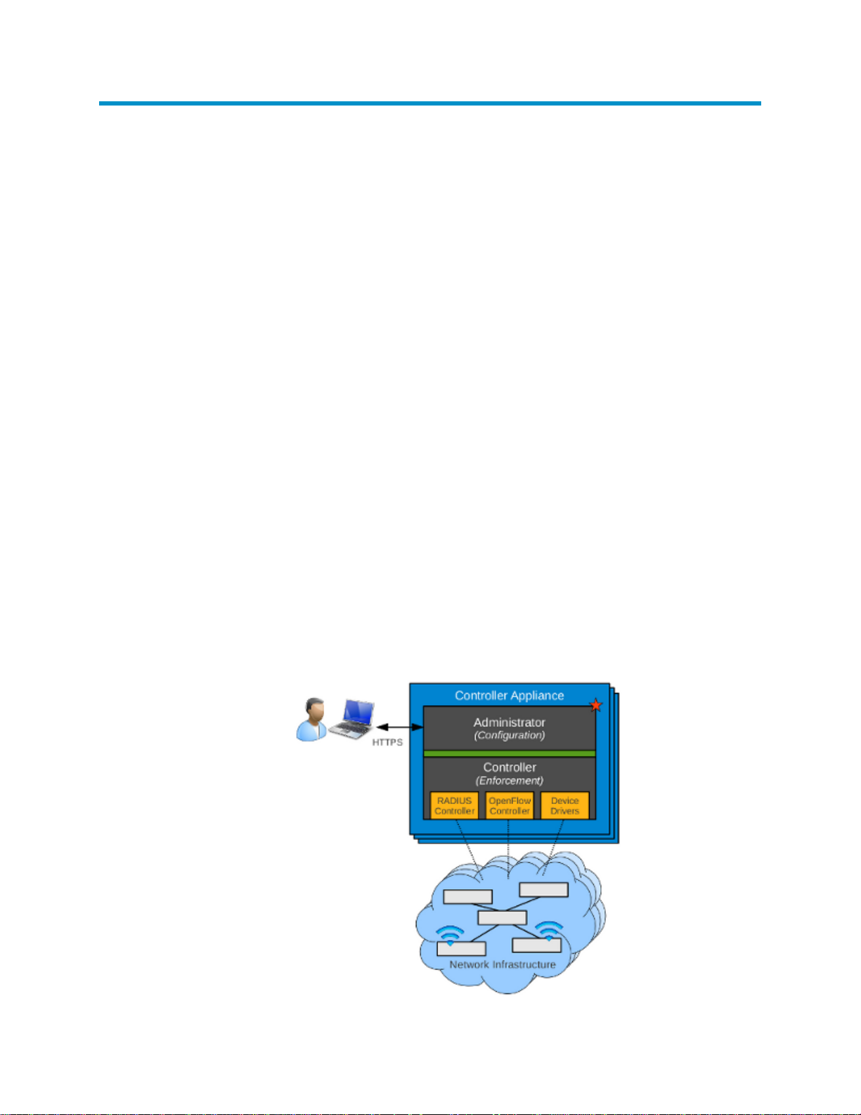
Overview
Regardless of the specific personality of the controller, the software stack consists of two major
tiers. The upper Administrator tier hosts functionality related to policy deployment, management,
personae interactions and external application interactions, for example slow-path, deliberating
operations. The lower Controller tier, on the other hand, hosts policy enforcement, sensing, device
interactions, flow interactions, for example fast-path, reflex, muscle-memory like operations. The
interface(s) between the two tiers provide a design firewall and are elastic in that they can change
along with the personality of the overall controller. Also, they are governed by a rule that no
enforcement-related synchronous interaction will cross from the Controller to Administrator tier.
Figure 1 Controller Tiers
1
Page 7
The Administration tier of the controller will host a web-layer through which software modules
installed on the appliance can expose REST APIs [1] [2] (or RESTful web services) to other external
entities. Similarly, modules can extend the available web-based GUI to allow network
administrators and other personae to directly interact with the features of the software running on
the SDN Controller.
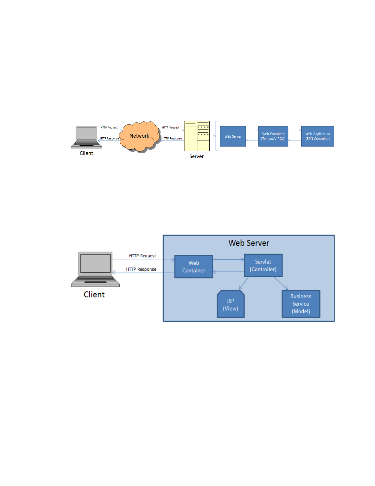
A web application is an application that is accessed by users over a network such as the Internet
or an intranet. The HP VAN SDN Controller runs on a web server as illustrated in Figure 2.
Figure 2 Web Application Architecture
Servlets [3] [4] is the technology used for extending the functionality of the web server and for
accessing business systems. Servlets provide a component-based, platform-independent method for
building Web-based applications.
SDN applications do not implement Servlets directly but instead they implement RESTful web
services [1] [2] which are based on Servlets; however RESTful web services also act as controllers
as described in the pattern from Figure 3.
Figure 3 Web Application Model View Controller Pattern
Basic Architecture
The principal software stack of the appliance uses OSGi framework (Equinox) [5] [6] and a
container (Virgo) [7] as a basis for modular software deployment and to enforce service
provider/consumer separation. The software running in the principal OSGi container can interact
with other components running as other processes on the appliance. Preferably, such IPC
interactions will occur using a standard off-the shelf mechanism, for instance RabbitMQ, but they
can exploit any means of IPC best suited to the external component at hand. Virgo, based on
Tomcat [8], is a module-based Java application server that is designed to run enterprise Java
applications with a high degree of flexibility and reliability. Figure 4 illustrates the HP VAN SDN
Controller software stack.
2
Page 8
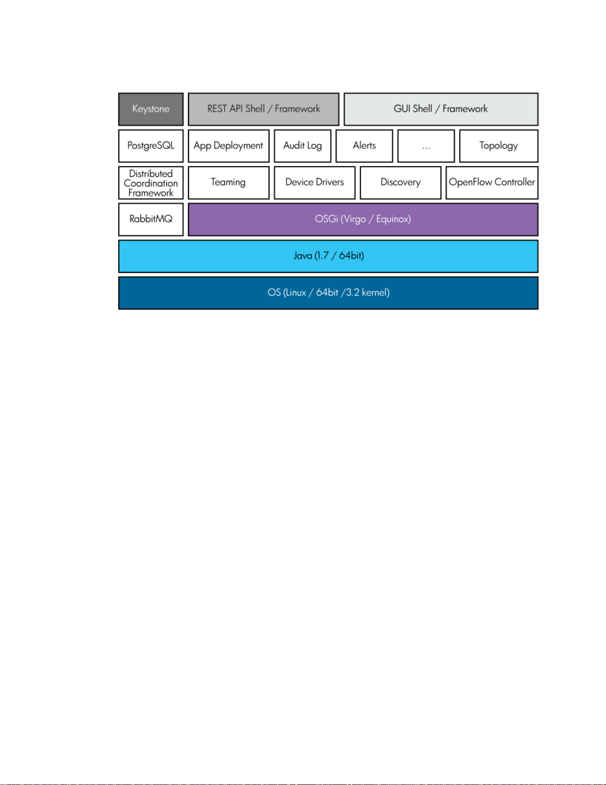
Figure 4 HP VAN SDN Controller Software Stack
Jersey [2] is a JAX-RS (JSR 311) reference Implementation for building RESTful Web services. In
Representational State Transfer (REST) architectural style, data and functionality are considered
resources, and these resources are accessed using Uniform Resource Identifiers (URIs), typically
links on the web. REST-style architectures conventionally consist of clients and servers and they are
designed to use a stateless communication protocol, typically HTTP. Clients initiate requests to
servers; servers process requests and return appropriate responses. Requests and responses are
built around the transfer of representations of resources. Clients and servers exchange
representations of resources using a standardized interface and protocol. These principles
encourage RESTful applications to be simple, lightweight, and have high performance.
The HP VAN SDN Controller also offers a framework to develop Web User Interfaces - HP SKI. The
SKI Framework provides a foundation on which developers can create a browser-based web
application.
The HP VAN SDN Controller makes use of external services providing APIs that allow SDN
applications to make use of them.
Keystone [9] is an external service that provides authentication and high level authorization
services. It supports token-based authentication scheme which is used to secure the RESTful web
services (Or REST APIs) and the web user interfaces.
Hazelcast[10] is an in-memory data grid management software that enables: Scale-out
computing, resilience and fast, big data.
Apache Cassandra [10] is a high performance, extremely scalable, fault tolerant (no single point
of failure), distributed post-relational database solution. Cassandra combines all the benefits of
Google Bigtable and Amazon Dynamo to handle the types of database management needs that
traditional RDBMS vendors cannot support.
Figure 5 illustrates with more detail the tiers that compose the HP VAN SDN Controller. It shows
the principal interfaces and their roles in connecting components within each tier, the tiers to each
other and the entire system to the external world.
3
Page 9

The approach aims to achieve connectivity in a controlled manner and without creating undue
dependencies on specifics of component implementations. The separate tiers are expected to
interact over well-defined mutual interfaces, with decreasing coarseness from top to bottom. This
means that on the way down, high-level policy communicated as part of the deployment
interaction over the external APIs is broken down by the upper tier into something similar to a
specific plan, which gets in turn communicated over the inter-tier API to the lower controller tier.
The controller then turns this plan into detailed instructions which are either pre-emptively
disseminated to the network infrastructure or are used to prime the RADIUS or OpenFlow [11] [ 12 ]
controllers so that they are able to answer future switch (other network infrastructure device)
queries.
Similarly, on the way up, the various data sensed by the controller from the network infrastructure,
regarding its state, health and performance, gets aggregated at administrator tier. Only the
administrator tier interfaces with the user or other external applications. Conversely, only the
controller tier interfaces with the network infrastructure devices and other supporting controller
entities, such as RADIUS, OpenFlow [11] [12], MSM controller software, and so on.
4
Page 10
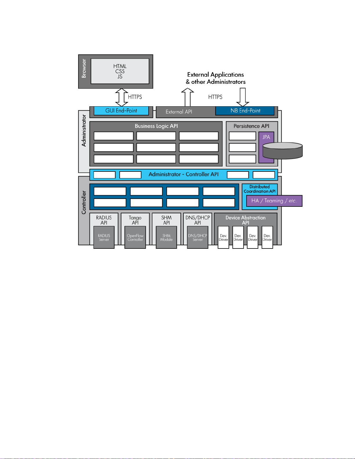
Figure 5 HP VAN SDN Controller Tiers
•
•
•
•
•
•
•
•
Internal Applications vs. External Applications
Internal applications (“Native” Applications / Modules) are ideal to exert relatively fine-grained,
frequent and low-latency control interactions with the environment, for example, handling packet-in
events. Some key points to consider when developing internal applications:
Authored in Java or a byte-code compatible language, e.g. Scala, or Scala DSL.
Deployed on the SDN Controller platform as collections of OSGi bundles.
Built atop services (Java APIs) exported and advertised by the platform and by other
applications.
Export and advertise services (Java APIs) to allow interactions with other applications.
Dynamically extend SDN Controller REST API surface.
Dynamically extend SDN Controller GUI by adding navigation categories, items, views, and
so on.
Integrate with the SDN Controller authentication & authorization framework.
Integrate with the SDN Controller Persistency & Distributed Coordination API.
Internal applications are deployed on the HP VAN SDN Controller and they interact with it by
consuming business services (Java APIs) published by the controller in the SDK.
5
Page 11

External applications are suitable to exert relatively coarse-grained, infrequent, and high-latency
•
•
•
•
Acronym
Description
DTO
Data Transfer Object
HP
Hewlett-Packard
HTTP
Hypertext Transfer Protocol
HTTPS
Hypertext Transfer Protocol Secure
HW
Hardware
LAN
Local Area Network
OF
OpenFlow
OSGi
Open Service Gatway Initiative
OWASP
Open Web Application Security Project
SNMP
Simple Network Management Protocol
VLAN
Virtual LAN
control interactions with the environment, such as path provisioning and flow inspections. External
applications can have these characteristics:
This can be written any language capable of establishing a secure HTTP connection.
Example: Java, C, C++, Python, Ruby, C#, bash, and so on.
They can be deployed on a platform of choice outside of the SDN Controller platform.
They use REST API services exported and advertised by the platform and by other
applications.
They do not extend the Java APIs, REST APIs, or GUI of the controller.
This guide describes writing and deploying internal applications. For information about the REST
APIs you can use for external applications, see the HP VAN SDN Controller REST API Reference
Guide.
Acronyms and Abbreviations
There are many acronyms and abbreviations that are used in this document. Table 1 contains some
of the more commonly used acronyms and abbreviations.
Table 1 Commonly Used Acronyms and Abbreviations
CLI Command Line Interface
6
Page 12

2 Establishing Your Test and Development
•
•
Environments
The suggested development environment contains two separate environments, a Test Environment
and a Development Environment. It is recommended to use a different machine for each of these
environments. The Test Environment is where the HP VAN SDN Controller and all the dependency
systems will be installed; it will be very similar to a real deployment, however virtual machines [13]
are useful during development phase. The Development Environment will be formed by the tools
needed to create, build and package the application. Once the application is ready for
deployment, the test environment will be used to install it.
One reason to keep these environments separated is because distributed applications may need a
team set up to test the application (Cluster of controllers). Another reason is that some unit test
and/or integration tests (RESTful Web Services [1] [2] for example) might open ports that are
reserved for services offered or consumed by the controller.
Test Environment
Installing HP VAN SDN Controller
To install the SDN controller follow the instructions from the HP VAN SDN Controller Installation
Guide [14].
Authentication Configuration
The HP VAN SDN Controller uses Keystone [9] for identity management. When it is installed, two
users are created, "sdn" and "rsdoc", both with a default password of "skyline". This password
can be changed using the keystone command-line interface from a shell on the system where the
controller was installed: Follow the instructions from the HP VAN SDN Controller Installation Guide
[14].
Development Environment
Pre-requisites
The development environment requirements are relatively minimal. They comprise of the following:
Operating System
Supported operating systems include:
Windows 7or later with MKS 9.4p1
Ubuntu 10.10 or later
7
Page 13
•
Java
Maven
Curl
OSX Snow Leopard or later.
The Software Development Language used is Java SE SDK 1.6 or later. To install Java go to [ 15 ]
and follow the download and installation instructions.
Apache Maven is a software project management and comprehension tool. Based on the concept
of a project object model (POM), Maven can manage a project's build, reporting and
documentation from a central piece of information [16].
To install Maven go to [16] and follow the download and installation instructions. Note that if you
are behind a fire-wall, you may need to configure your ~/.m2/settings.xml appropriately to
access the Internet-based Maven repositories via proxy, for more information see Maven Cannot
Download Required Libraries on page 251.
Maven 3.0.4 or newer is needed. To verify the installed version of Maven execute the following
command:
$ mvn –version
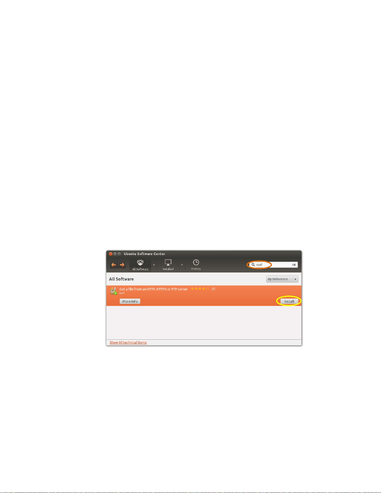
Curl (or cURL) is a command line tool for transferring data with URL syntax. This tool is optional.
Follow the instruction from [17] to install Curl, or if you use Linux Ubuntu as development
environment you may use the Ubuntu Software Center to install it as illustrated in Figure 6.
Figure 6 Installing Curl via Ubuntu Software Center
IDE
An IDE, or an Integrated Development Environment, is a software application that provides a
programmer with many different tools useful for developing. Tools that bundled with an IDE may
include: an editor, a debugger, a compi ler, and more. Eclipse is a popular IDE that can be used to
program in Java and for developing applications. Eclipse might be referenced in this guide.
HP VAN SDN Controller SDK
Download the HP VAN SDN Controller SDK from [18]. The SDK is contained in the hp-sdn-sdk-*.zip
file (for example: hp-sdn-sdk-2.0.0.zip). Unzip its contents in any location. To install the SDN
Controller SDK jar files into the local Maven repository, execute the SDK install tool from the
8
Page 14
Javadoc
directory where the SDK was unzipped, as follows (Note: Java SDK and Maven must already be
installed and properly configured):
$ bin/install-sdk
To verify that the SDK has been properly installed look for the HP SDN libraries installed in the local
Maven repository at:
~/.m2/repository/com/hp.
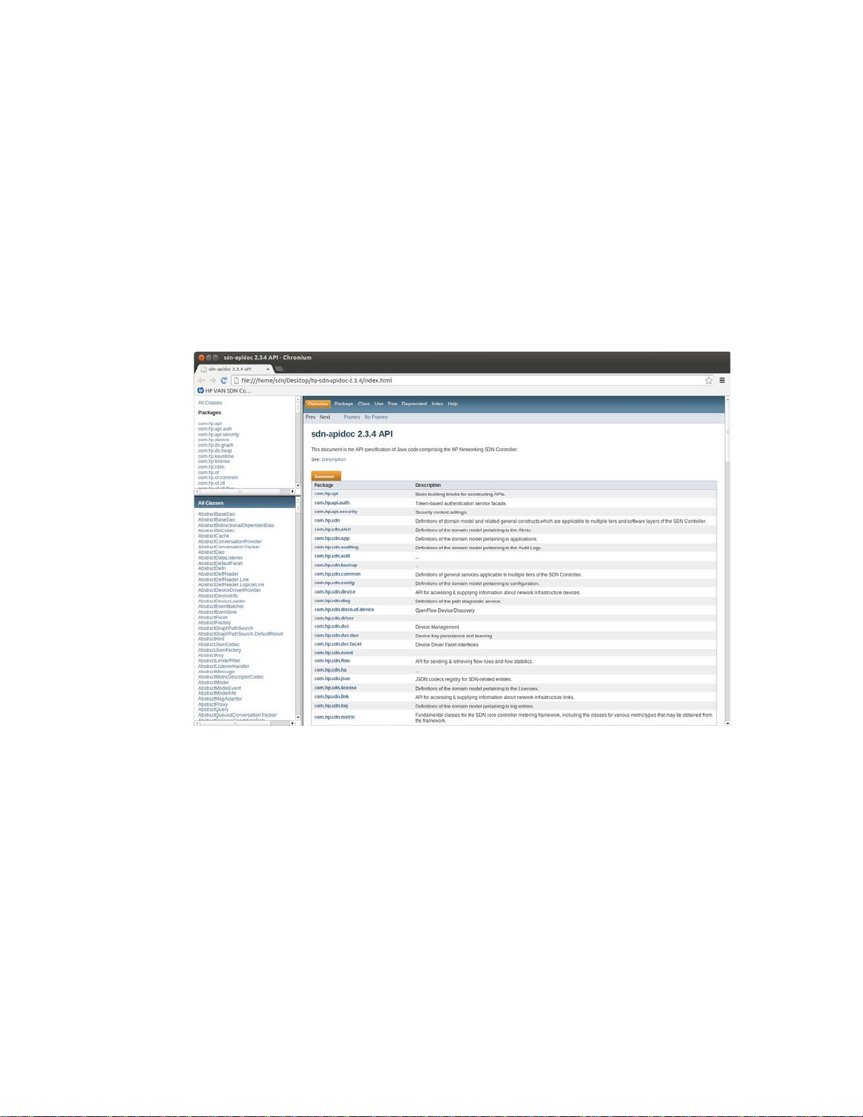
The controller Java APIs are documented in Javadoc format in the hp-sdn-apidoc-*.jar file.
Download the file and unzip its contents. To view the Java API documentation, open the index.html
file. Figure 7 illustrates an example of the HP VAN SDN Controller documentation.
Figure 7 HP VAN SDN Controller Javadoc
9
Page 15

3 Developing Applications
•
•
•
•
•
•
•
•
Internal applications (“Native” Applications / Modules) are ideal to exert relatively fine-grained,
frequent and low-latency control interactions with the environment, for example, handling packet-in
events. Some key points to consider when developing internal applications:
Authored in Java or a byte-code compatible language, e.g. Scala, or Scala DSL.
Deployed on the SDN Controller platform as collections of OSGi bundles.
Built atop services (Java APIs) exported and advertised by the platform and by other
applications.
Export and advertise services (Java APIs) to allow interactions with other applications.
Dynamically extend SDN Controller REST API surface.
Dynamically extend SDN Controller GUI by adding navigation categories, items, views, and
so on.
Integrate with the SDN Controller authentication & authorization framework.
Integrate with the SDN Controller Persistency & Distributed Coordination API.
Internal applications are deployed on the HP VAN SDN Controller and they interact with it by
consuming business services (Java APIs) published by the controller in the SDK.
Introduction
Figure 8 illustrates the various classes of software modules categorized by the nature of their
responsibilities and capabilities and the categories of the software layers to which they belong.
Also shown are the permitted dependencies among the classes of such modules. Note the explicit
separation of the implementations from interfaces (APIs). This separation principle is strictly
enforced in order to maintain modularity and elasticity of the application. Also note that these
represent categories, not necessarily the actual modules or components. This diagram only aims to
highlight the classes of software modules.
10
Page 16
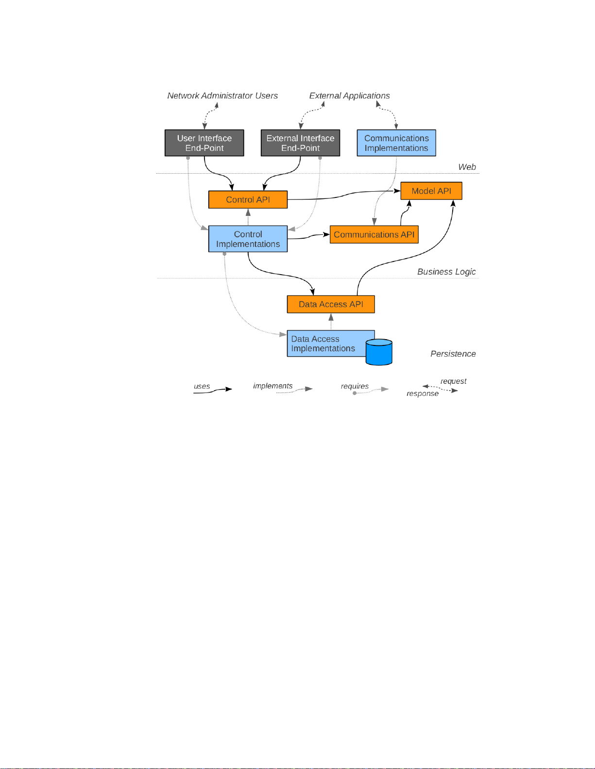
Figure 8 HP Application Modules
11
Page 17

Web Layer
Components in this layer are responsible for receiving and consuming appropriate external
representations (XML, JSON, binary...) suitable for communicating with various external entities
and, if applicable, for utilizing the APIs from the business logic layer to appropriately interact with
the business logic services to achieve the desired tasks and/or to obtain or process the desired
information.
User Interface End-Point (REST API) and end-point resources for handling inbound requests
providing control and data access capabilities to the administrative GUI.
External Interface End-Point (REST API) are end-point resources for handling inbound requests
providing control and data access capabilities to external applications, including other
orchestration and administrative tools (for example IMC, OpenStack , etc.)
Business Logic Layer
Components in this layer fall into two fundamental categories: model control services and
outbound communications services, and each of these are further subdivided into public APIs and
private implementations.
The public APIs are composed of interfaces and passive POJOs [19], which provide the domain
model and services, while the private implementations contain the modules that implement the
various domain model and service interfaces. All interactions between different components must
occur solely using the public API mechanisms.
Model API—Interfaces & objects comprising the domain model. For example: the devices, ports,
network topology and related information about the discovered network environment.
Control API—Interfaces to access the modeled entities, control their life-cycles and in general to
provide the basis for the product features to interact with each other.
Communications API—Interfaces which define the outbound forms of interactions to control,
monitor and discover the network environment.
Control Implementations—Implementations of the control API services and domain model.
Communications Implementations—Implementations of the outbound communications API
services. They are responsible for encoding / transmitting requests and receiving / decoding
responses.
Health Service API—Allows an application to report its health to the controller (via the
HealthMonitorable interface or proactively submitting health information to the HealthService
directly via the updateHealth method) and/or listen to health events from the controller and other
applications (via the HealthListener interface). There are 3 types of health statuses:
• OK – A healthy status to denote that an application is functioning as expected.
• WARN – An unhealthy status to denote that an application is not functioning as expected
and needs attention. This status is usually accompanied by a reason as to why the
application reports this status to provide clues to remedy the situation.
• CRITICAL – An unhealthy status to denote that some catastrophic event has happened to
the application that affects the controller’s functionality. When the controller receives a
CRITICAL event, it will assume that its functionality has been affected, and will proceed to
12
Page 18

shutdown the Openflow port to stop processing Openflow events. If in a teaming
•
•
•
•
•
•
•
•
•
•
environment, the controller will remove itself from the team.
Persistence Layer
Data Access API—Interfaces, which prescribe how to persist and retrieve the domain model
information, such as locations, devices, topology, etc. This can also include any prescribed routing
and flow control policies.
Data Access Implementations—Implementations of the persistence services to store and
retrieve the SDN-related information in a database or other non-volatile form.
Authentication
Controller REST APIs are secured via a token-based authentication scheme. OpenStack Keystone
[9] is used to provide the token-based authentication.
This security mechanism:
Provides user authentication functionality with RBAC support.
Completely isolates the security mechanism from the underlying REST API.
Works with OpenStack Keystone.
Exposes a REST API to allow any authentication server that implements this REST API to be
hosted elsewhere (outside the SDN appliance).
This security mechanism does not:
Provide authorization. Authorization needs to be provided by the application based on the
authenticated subject's roles.
Support filtering functionality such as black-listing or rate-limiting.
To achieve isolation of security aspects from the API, authentication information is encapsulated by
a token that a user receives by presenting his/her credentials to an Authentication Server. The user
then uses this token (via header X-Auth-Token) in any API call that requires authentication. The
token is validated by an Authentication Filter that fronts the requested API resource. Upon
successful authentication, requests are forwarded to the RESTful APIs with the principal's
information such as:
User ID
User name
User roles
Expiration Date
Upon unsuccessful authentication (either no token or invalid token), it is up to the application to
deny or allow access to its resource. This flexibility allows the application to implement its own
authorization mechanism, such as ACL-based or even allow anonymous operations on certain
resources.
The flow of token-based authentication in the HP VAN SDN Controller can be summarized as
illustrated in Figure 9.
13
Page 19
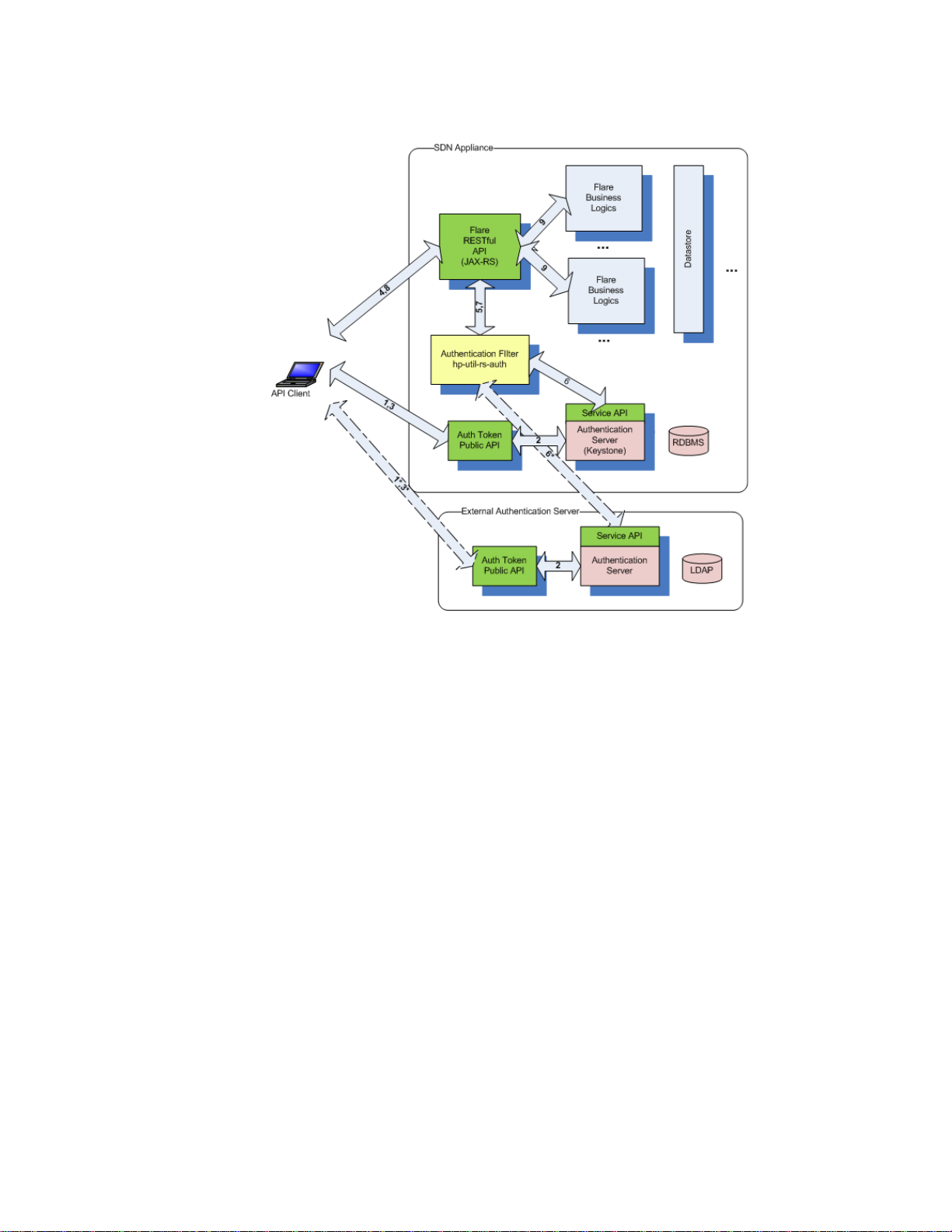
Figure 9 Token-based Authentication Flow
1) API Client presents credentials (username/password) to the AuthToken REST API.
2) Authentication is performed by the backing Authentication Server. The SDN Appliance
includes a local Keystone-based Authentication Server, but the Authentication Server may also
be hosted elsewhere by the customer (and maybe integrated with an enterprise directory such
as LDAP for example), as long as it implements the AuthToken REST API (described elsewhere).
The external Authentication Server use-case is shown by the dotted-line interactions. If the user
is authenticated, the Authentication Server will return a token.
3) The token is returned back to the API client.
4) The API client includes this token in the X-Auth-Token header when making a request to the HP
VAN SDN Controller’s RESTful API.
5) The token is intercepted by the Authentication Filter (Servlet Filter).
6) The Authentication Filter validates the token with the Authentication Server via another
AuthToken REST API.
7) The validation status is returned back to the REST API.
8) If the validation is unsuccessful (no token or invalid token), the HP VAN SDN Controller will
return a 401 (Unauthorized) status back to the caller.
9) If the validation is successful, the actual the HP VAN SDN Controller REST API will be invoked
and business logics ensue.
In order to isolate services and applications from Keystone specifics, two APIs in charge of
providing authentication services (AuthToken REST API's) are published:
14
Page 20

Public API:
•
•
•
•
•
•
•
•
1) Create token. This accepts username/password credentials and return back a unique token with
some expiration.
Service API:
1) Revoke token. This revokes a given token.
2) Validate token. This validates a given token and returns back the appropriate principal's
information.
Authentication services have been split into these two APIs to limit sensitive services (Service API) to
only authorized clients.
REST API
Internal applications do not make use of the HP VAN SDN Controller’s REST API, they extend it by
defining their own RESTful Web Services. Internal applications make use of the business services
(Java APIs) published by the controller. For external applications consult the RESTful API
documentation (or Rsdoc) as described at Rsdoc Live Reference on page 17.
Representational State Transfer (REST) defines a set of architectural principles by which Web
services are designed focusing on a system's resources, including how resource states are
addressed and transferred over HTTP by a wide range of clients written in different languages
[20].
Concrete implementation of a REST Web service follows four basic design principles:
Use HTTP methods explicitly.
Be stateless.
Expose directory structure-like URIs.
Transfer XML, JavaScript Object Notation (JSON), or both.
One of the key characteristics of a RESTful Web service is the explicit use of HTTP. HTTP GET, for
instance, is defined as a data-producing method that's intended to be used by a client application
to retrieve a resource, to fetch data from a Web server, or to execute a query with the expectation
that the Web server will look for and respond with a set of matching resources [20].
REST asks developers to use HTTP methods explicitly and in a way that's consistent with the
protocol definition. This basic REST design principle establishes a one-to-one mapping between
create, read, update, and delete (CRUD) operations and HTTP methods. According to this
mapping:
To create a resource on the server, use POST.
To retrieve a resource, use GET.
To change the state of a resource or to update it, use PUT.
To remove or delete a resource, use DELETE.
See [1] for guidelines to design REST APIs or RESTful Web Services and Creating a REST API on
page 169 for an example.
15
Page 21
REST API Documentation
In addition to the Rsdoc, the HP VAN SDN Controller REST API provides information for interacting
with the controller’s REST API.
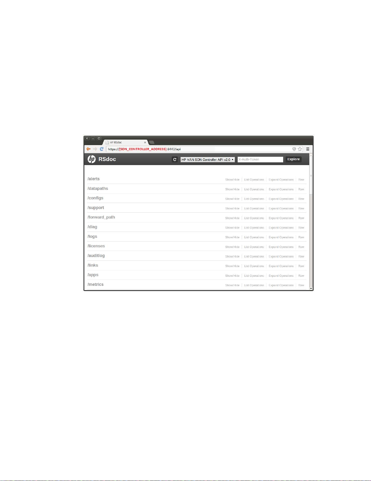
Rsdoc
Rsdoc is a semi-automated interactive RESTful API documentation. It offers a useful way to interact
with REST APIs.
Figure 10 RSdoc
It is called RSdoc because is a combination of JAX-RS annotations [2] and Javadoc [21] (Illustrated
in F i g u r e 11 ).
16
Page 22
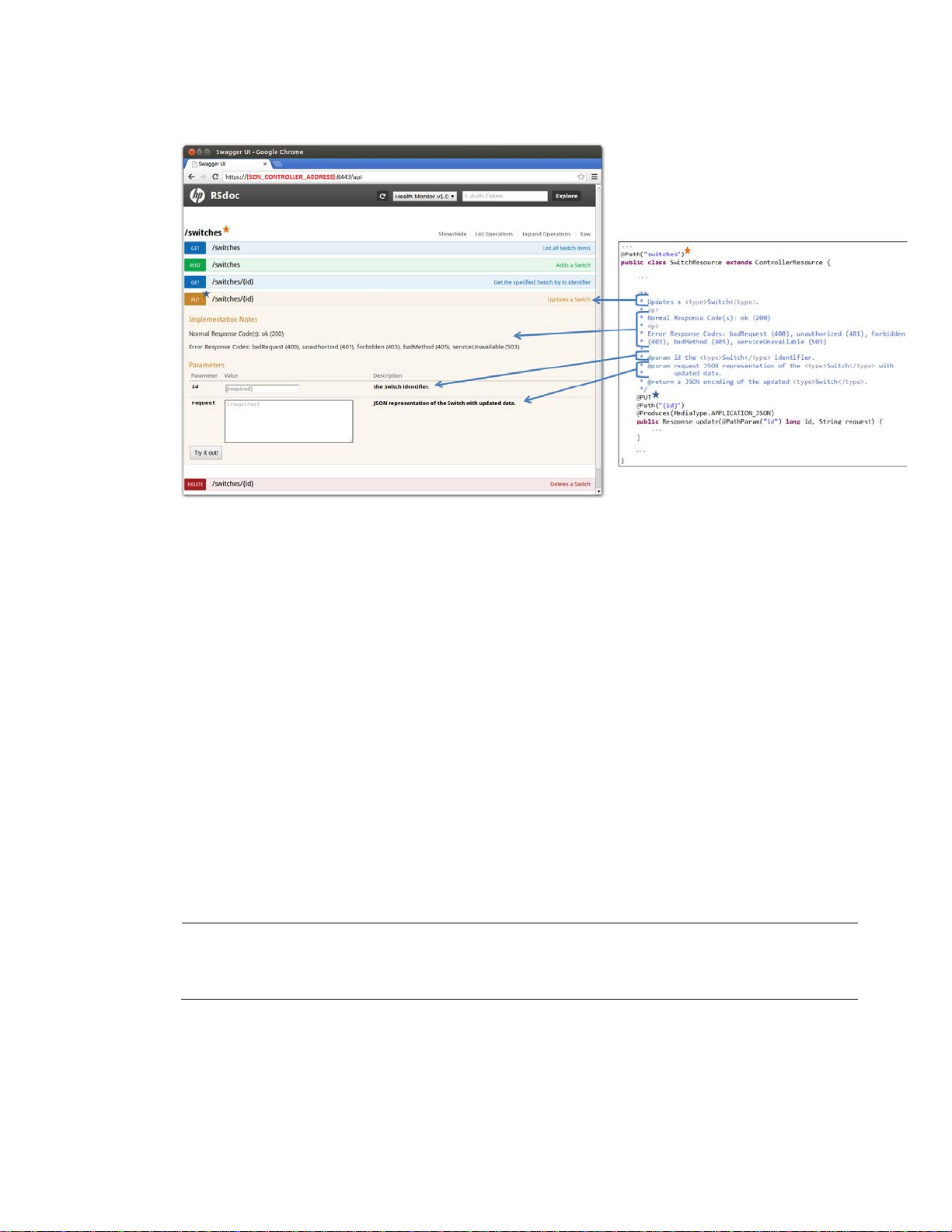
Figure 11 RSdoc, JAX-RS and Javadoc
NOTE
Use the correct password if it was changed following instructions from
on
page 7.
JAX-RS annotations and Javadoc are already written when implementing RESTful Web Services, and
they are re-used to generate an interactive API documentation.
Rsdoc Extension
The HP VAN SDN Controller SDK offers a method to extend the Rsdoc to include applications
specific RESTful Web Services (As the example illustrated in F i g u r e 11). Since JAX-RS annotations and
Javadoc are already written when implementing RESTful Web Services, in order to enable an
application to extend the RSdoc is relatively easy and automatic: a few configuration files need to
be updated. See Creating RSdoc on page 193 for an example.
Rsdoc Live Reference
To access the HP VAN SDN Controller’s Rsdoc (including extensions by applications):
1. Open a browser at https
2. Get an authentication token by entering the following authentication JSON document:
{"login":{"user":"sdn","password":"skyline","domain":"sdn"}} (as illustrated in Fi g ur e 12 ).
://SDN_CONTROLLER_ADDRESS:8443/api (As illustrated in F igu re 10 ).
Authentication Configuration
17
Page 23
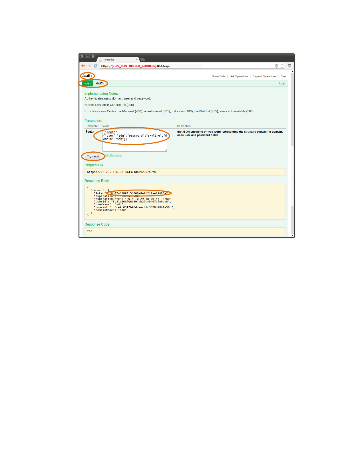
Figure 12 Authenticating via RSdoc Step 1
3. Set the authentication token as the X-AUTH-TOKEN in the RSdoc and then click “Explore,” as
illustrated in Fi g u re 13. From this point all requests done via RSdoc will be authenticated as long
as the token is valid.
18
Page 24
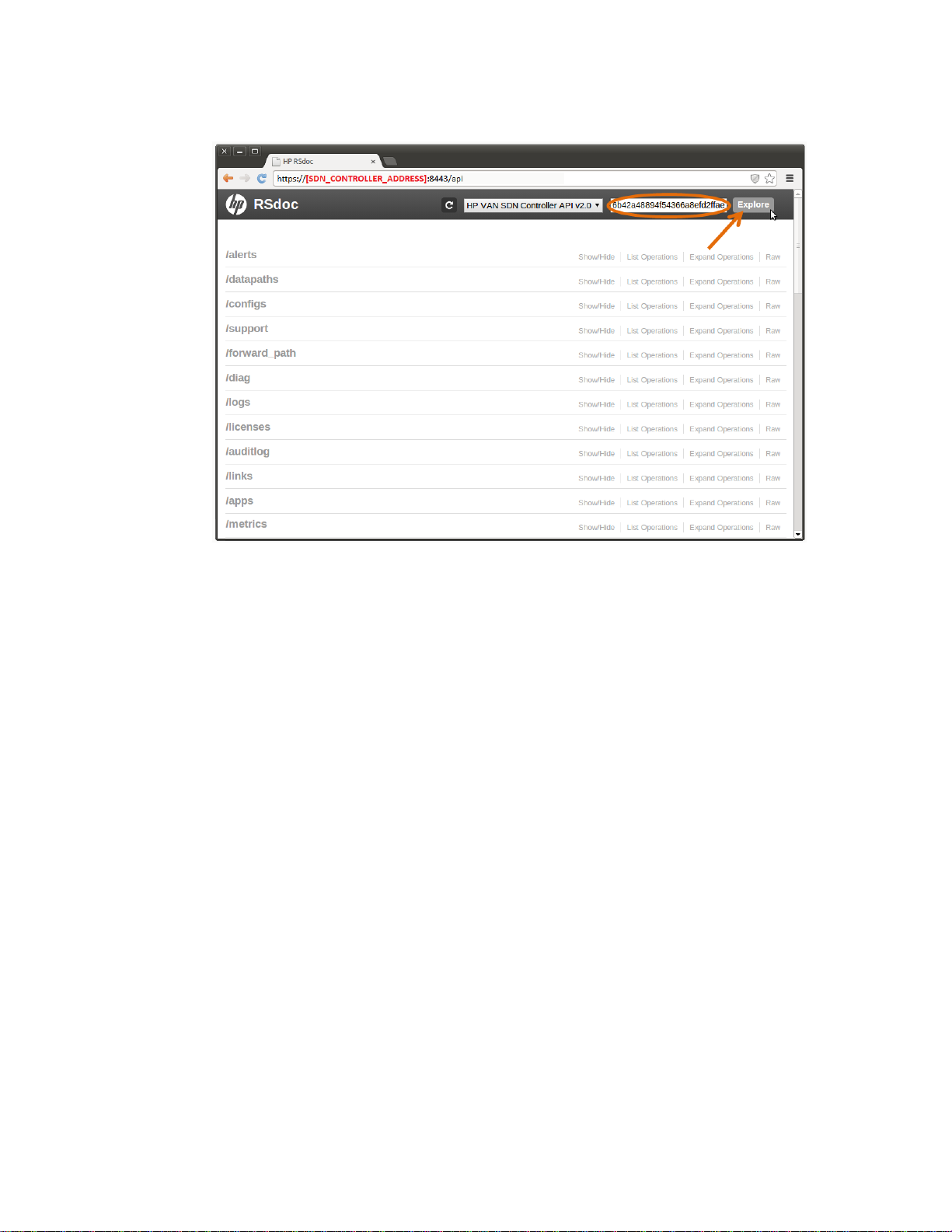
Figure 13 Authenticating via RSdoc Step 2
•
•
•
•
Audit Logging
The Audit Log retains information concerning activities, operations and configuration changes that
have been performed by an authorized end user. The purpose of this subsystem is to allow tracking
of significant system changes. This subsystem provides an API which various components can use to
record the fact that some important operation occurred, when and who triggered the operation and
potentially why. The subsystem also provides means to track and retrieve the recorded information
via an internal API as well as via external REST API. An audit log entry, once created, may not be
modified. Audit log entries, once created, may not be selectively deleted. Audit log entries are only
removed based on the age out policy defined by the administrator.
Audit Log data is maintained in persistence storage (default retention period is one year) and is
presented to the end user via both the UI and the REST API layers.
The audit log framework provides a cleanup task that is executed daily (by default) that ages out
audit log entries from persistent storage based on the policy set by the administrator.
An audit log entry consists of the following:
User—a string representation of the user that performed the operation which triggered the
audit log entry.
Time-stamp—the time that the audit log entry was created. The time information is persisted
in an UTC format.
Activity—a string representation of the activity the user was doing that triggered this audit log
entr y.
Data—a string description for the audit log entry. Typically, this contains the data associated
with the operation.
19
Page 25

•
•
•
•
•
•
•
•
Origin—a string representation of the application or component that originated this audit log
entr y.
Controller ID—the unique identification of the controller that originated the audit log entry.
Applications may contribute to the Audit Log via the Audit Log service. When creating an audit log
entry the user, activity, origin and data must be provided. The time-stamp and controller
identification is populated by the audit log framework. To contribute an audit log entry, use the
post(String us er, String origi n, String activi ty, String descr ip tion)
method provided by the AuditLogService API. This method will return the object that was created.
The strings associated with the user, origin and activity are restricted to a maximum of 255
characters, whereas the description string is restricted to a maximum of 4096 characters.
An example of an application consuming the Audit Log service is described at Auditing with Logs on
page 215.
Alert Logging
The purpose of this subsystem is to allow for management of alert data. The subsystem comprises of
an API which various components can use to generate alert data. The subsystem also provides
means to track and retrieve the recorded information via an internal API as well as via external REST
API. Once an alert entry has been created the state of the alert (active or not) is the only
modification that is allowed.
Alert data is maintained in persistent storage (default retention period is 14 days) and is presented
to the end user via both the UI and REST API layers. The alert framework provides a cleanup task
that is executed daily (by default) that ages out alert data from persistent storage based on the
policy set by the administrator.
An alert consists of the following:
Severity—one of Informational, Warning or Critical
Time-stamp—The time the alert was created. The time information is persisted in an UTC
format.
Description—a string description for the alert
Origin—a string representation of the application or component that originated the alert
Topic—the topic related to the alert. Users can register for notification when alerts related to
a given topic or set of topics occur
Controller ID—the unique identification of the controller that originated the alert
Applications may contribute alerts via the Alert service. When creating an alert the severity, topic,
origin and data must be provided. The time-stamp and controller identification is populated by the
alert framework. To contribute an alert, use the
post(Severity severity, Ale rtTopic topic, String origin, Stri ng data)
method provided by the AlertService API. This method returns the Alert DTO object that was created.
The string associated with the origin is restricted to a maximum of 255 characters, as well as the
data string.
An example of an application consuming the Alert service is described at Posting Alerts on page
212 .
20
Page 26

Configuration
The SDN controller presents configurable properties and allows the end user to modify
configurations via both the UI and REST API layers. The HP VAN SDN Controller uses the OSGi
Configuration Admin [22] [23] and MetaType [24] [25] services to present the configuration data.
For an application to provide configuration properties that are automatically presented by the SDN
controller, they must provide the MetaType information for the configurable properties. The metatype
information is contained in a “metatype.xml” file that must be present in the OSGI-INF/metatype
folder of the application bundle.
The necessary metatype.xml can be automatically generated via the use of the Maven SCR
annotations [26] and Maven SCR [27] plugin in a Maven pom.xml file for the application (See Root
POM File on page 139). The SCR annotations must be included as a dependency, and the SCR
plug-in is a build plugin.
Application pom.xml Example:
<?xml versio n="1.0" encoding="UTF-8"?>
<project xmlns=http://ma ven .apache.org/POM/4.0.0
xmlns:xsi="http://www.w3.org/2001/XMLSchema-instance"
xsi:schemaLocation="http://maven.apache.org/POM/4.0.0
http://maven.apache.org/maven-v4_0_0.xsd">
...
<dependencies>
...
<dependency>
<groupId>org.apache.felix</groupId>
<artifactId>org.apache.felix.scr.annotations</artifactId>
<version>1.9.4</version>
</dependency>
</dependencies>
<build>
<plugins>
...
<plugin>
<groupId>org.apache.felix</groupId>
<artifactId>maven-scr-plugin</artifactId>
<version>1.13.0</version>
<executions>
<execution>
<id>generate-scr-srcdescriptor</id>
<goals>
<goal>scr</goal>
</goals>
</execution>
</executions>
<configuration>
<supportedProjectTypes>
21
Page 27

<supportedProjectType>bundle</supportedProjectType>
<supportedProjectType>war</supportedProjectType>
</supportedProjectTypes>
</configuration>
</plugin>
</plugins>
</build>
</project>
The component can then use Annotations to define the configuration properties as illustrated in the
following listing.
Configurable Property Key Definition Example:
package com.hp.hm.impl;
import org.apache.felix. scr .annotations.*;
...
@Component (metatype=true)
public class SwitchComponen t im plements SwitchService {
@Property(intValue = 100, description="Some Configuration")
protected static final St ring CONFIG_KE Y = " cfg.key";
...
}
The component is provided the configuration data by the OSGi framework as a Java Dictionary
object, which can be referenced as a basic Map of key -> value pairs. The key will always be a
Java String object, and the value will be a Java Object. A component will be provided the
configuration data at component initialization via an annotated “activate” method. Live updates to
a components configuration will be provided via an annotated “modified” method. Both of these
annotated methods should define a Map<String, Object> as an input parameter. The following
listing shows an example.
Configurable Property Example:
...
import com.hp.sdn.misc.C onf igUtils;
@Component (metatype=tru e)
public class SwitchComponen t im plements SwitchService {
@Property(intValue = 100, description="Some Configuration")
protected static final Stri ng CONFIG_KEY = "cfg.key";
private int someCf gVariable;
@Activate
protected void activate(Map<String, Object> config) {
someIntVariable = ConfigUtils.readInt(config, CONF IG_KEY, null, 100);
}
@Modified
protected void modified(Map<String, Object> config) {
22
Page 28

someIntVariable = ConfigUtils.readInt(config, CONF IG_KEY, null, 100);
•
•
•
•
}
...
}
As the configuration property value can one of several different kinds of Java object (Integer, Long,
String, etc.) a utility class is provided to read the appropriate Java object type from the configuration
map. The ConfigUtils.java class provides methods to read integers, longs, strings, Booleans and
ports from the configuration map of key -> value pairs. The caller must provide the following
information:
The configuration map
The key (string) for the desired property in the configuration map
A data Validator object (can be null)
A default value. The default value is returned if the provided key is not found in the
configuration map, if the key does not map to an Object of the desired type, or if a provided
data validator object rejects the value.
A Validator is a typed class which performs custom validation on a given configuration value. For
example, a data validator which only allows integer values between 10 and 20 is illustrated in the
following listing.
Configurable Property Validator Example:
...
import com.hp.sdn.misc.Validator;
public class MyValidator impl em ents Validator<Integer> {
@Override
public boolean isValid( In teger value) {
return ((10 <= value) && (value <= 20));
}
}
To use this validator with the ConfigUtils class to obtain the configuration value from the
configuration map, just include it in the method call:
MyValidato r myValidator = new My Validator();
ConfigUtils.readInt(config, CONFIG_KEY, myValidator, 15);
High Availability
Role orchestration
Role Orchestration Service provides a federated mechanism to define the role of teamed controllers
with respect to the network elements in the controlled domain. The role that a controller assumes in
relation to a network element would determine whether it has abilities to write and modify the
configurations on the network element, or has only read-only access to it.
As a preparation to exercise the Role Orchestration Service (ROS) in the HP VAN SDN Controller,
there are two pre-requisite operations that needs to be carried out beforehand:
23
Page 29

1) Create controller team: Using the teaming interfaces, a team of controllers need to be defined
for leveraging High Availability features.
2) Create Region: the network devices for which the given controller has been identified as a
master are grouped into “regions”. This grouping is defined in the HP VAN SDN Controller
using the Region interface detailed in subsequent sections.
Once the region definition(s) are in place, the ROS would take care of ensuring that a master
controller is always available to the respective network element(s) even when the configured master
experiences a failure or there is effectively a disruption of the communication channel between the
controller and the network device(s).
Failover: ROS would trigger the failover operation in two situations:
1) Controller failure: The ROS detects the failure of a controller in a team via notifications from
the teaming subsystem. If the ROS determines that the failed controller instance was master to
any region, it would immediately elect one of the backup (slave) controllers to assume the
mastership over the affected region.
2) Device disconnect: The ROS instance in a controller would get notified of a communication
failure with network device(s) via the Controller Service notifications. It would instantly federate
with all ROS instances in the team to determine if the network device(s) in question are still
connected to any of the backup (slave) controllers within the team. If that is the case, it would
elect one of the slaves to assume mastership over the affected network device(s).
Failback: When the configured master recovers from a failure and joins the team again, or when
the connection from the disconnected device(s) with the original master is resumed, ROS would
initiate a failback operation i.e. the mastership is restored back to the configured master as defined
in the region definition.
ROS exposes API’s through which interested applications can:
1) Create, delete or update a region definition
2) Determine the current master for a given device identified by a datapathId or IP address
3) Determine the slave(s) for a given device identified by a datapathId or IP address
4) Determine if the local controller is a master to a given device identified by a datapath
5) Determine the set of devices that a given controller is playing the master or slave role.
6) Register for region and role change notifications.
Details of the RegionService and RoleService APIs may be found at the Javadocs provided with the
SDK. See Javadoc on page 9 for details.
Illustrative usages of Role Service API’s
- To determine the controller which is currently playing the role of Master to a given datapath,
applications can use the following API’s depending on the specific need:
import com.hp.sdn.adm.ro le. RoleService;
import com.hp.sdn.adm.sy ste m.SystemInforamationServ ice;
…
public class SampleService {
// Mandatory dependency.
private final Sy stemInformationService sysIn foService;
24
Page 30

// Mandatory dependency.
private final Ro leService roleService;
public void doAct() {
IpAddress masterIp = roleService.getM aster(dpid).ip();
if(masterIp.equals(sysInfoService.
getSystem().getAddress())){
log.debug(“this cont ro ller is the master to {}”,
dpid);
// now that we know this controller has master privil ages
// we could for exam ple initiate wri te operations on the
// datapath – like sending flow-mods
}
}
}
- To determine the role that a controller is playing with respect to a given datapath
import com.hp.of.lib.msg .Co ntrollerRole;
import com.hp.sdn.adm.ro le. RoleService;
import com.hp.sdn.region .Co ntrollerNode;
import com.hp.sdn.region.ControllerNodeModel;
…
public class SampleService {
// Mandatory dependency.
private final Ro leService roleService;
public void doAc t() {
...
ControllerNode co ntroller = new Cont ro llerNodeModel(“10.1.1.1” );
Contro llerRole role = ro leService.ge tC urrentRole(controller,de viceIp);
switch(role){
case MASTER:
// the given controll er has master privilages
// we can trigger write-operations from that co ntroller
...
Break;
Case SLAVE:
// we have only read priv ileges
...
break;
default:
// indicates the cont roller and device are not associated
// to any region.
break;
25
Page 31

}
}
Notification on Region and Role changes
Applications can express interest in region change notifications using the addListener(...) API in
RegionService and providing an implementation of the RegionListener. A sample listener
implementation is illustrated in the following listing:
Region Listener Example:
import com.hp.sdn.adm.re gio n.RegionListener;
import com.hp.sdn.region .Re gion;
...
public class RegionListener Im pl implements Re gionListener {
...
@Override
public void added(Regio n re gion) {
log.debug(“Mast e r of ne w region: {}”, region.master() );
}
@Override
public void removed(Reg io n region) {
log.debug(“Mast e r of re moved region: {}”, region.mast er());
}
}
Similarly applications can express interest in role change notifications using the addListener(...) API
in RoleService and providing an implementation of the RoleListener. A sample listener
implementation is illustrated in the following listing:
Role Listener Example:
import com.hp.sdn.adm.ro le. RoleEvent;
import com.hp.sdn.adm.ro le. RoleListener;
...
public class RoleListenerIm pl implements RoleListener {
...
@Override
public void rolesAsserted(RoleEvent roleEvent) {
log.debug(“Previous master: {}”, roleEvent.oldMaster());
log.debug(“New m ast er: {}”, roleEvent.newMaster ());
log.debug(“Affected datapaths: {}”, roleEvent.data paths());
}
}
OpenFlow
OpenFlow messages are sent and received between the controller and the switches (datapaths) it
manages. These messages are byte streams, the structure of which is documented in the OpenFlow
Protocol Specification documents published by the Open Networking Foundation (ONF) [28].
26
Page 32

The Message Library is a Java implementation of the OpenFlow specification, providing facilities for
•
•
•
•
•
•
encoding and decoding OpenFlow messages from and to Java rich data types.
The controller handles the connections from OpenFlow switches and provides the means for upper
layers of software to interact with those switches via the ControllerService API.
The following figure illustrates this:
Figure 14 OpenFlow Controller
Message Library
The Message Library is a Java implementation of the OpenFlow specification, providing facilities for
encoding and decoding OpenFlow messages from and to Java rich data types.
Design Goals
The following are the overall design goals of the library:
To span all OpenFlow protocol versions
However, actively supporting just 1.0.0 and 1.3.2
To be extensible
Easily accommodating future versions
To provide an elegant, yet simple, API for handling with OpenFlow messages
To reduce the burden on application developers
Insulating developers from differences across protocol versions, as much as possible
To expose the semantics but hide the syntax details
Developers will not be required to encode and decode bitmasks, calculate message
lengths, insert padding, etc.
To be robust and type-safe
Working with Java enumerations and types
27
Page 33

Design Choices
•
•
•
•
•
•
•
Some specific design choices were made to establish the underlying principles of the
implementation, to help meet the goals specified above.
All OpenFlow messages are fully creatable/encodable/decodable, making the library
completely symmetrical in this respect.
The controller (or app) never creates certain messages (such as PortStatus, FlowRemoved,
However, providing a complete solution allows us to emulate OpenFlow switches in Java
Message instances, for the most part, are immutable.
This means a single instance can be shared safely across multiple applications (and
This implies that the structures that make up the message (ports, instructions, actions, etc.)
Where possible, “Data Types” will be used to encourage API type-safety – see the
Where bitmasks are defined in the protocol, Java enumerations are defined with a constant
for each bit.
MultipartReply, etc.) as these are only ever generated by the switch. Technically, we
would only need to decode those messages, never encode them.
code. This facilitates the writing of automated tests to verify switch/controller interactions
in a deterministic manner.
multiple threads) without synchronization.
must also be immutable.
Javadocs for com.hp.util.ip and com.hp.of.lib.dt.
A specific bitmask value is represented by a Set of the appropriate enumeration
constants.
For example: Set<PortConfig>
A message instance is mutable only while the message is under construction (for example, an
application composing a FlowMod message). To be sent through the system it must be
converted to its immutable form first.
To create and send a message, an application will:
Use the Message Factory to create a mutable message of the required type
Set the state (payload) of the message
Make the message immutable
Send the message via the ControllerService API.
The Core Controller will use the Message Factory to encode the message into its byte-stream
form, for transmitting to the switch.
The Core Controller will use the Message Factory to decode incoming messages from their
byte-stream form into their (immutable) rich data type form.
28
Page 34

Figure 15 Message Factory Role
•
•
•
•
•
•
Message Composition and Type Hierarchy
All OpenFlow message instances are subclasses of the OpenflowMessage abstract class. Every
message includes an internal Header instance that encapsulates:
The protocol version
The message type
The message length (in bytes)
The transaction ID (XID)
In addition to the header, specific messages may include:
Data values, such as “port number”, “# bytes processed”, “metadata mask”, “h/w address”,
etc.
These values are represented by Java primitives, enumeration constants, or data types.
Other common structures, such as Ports, Matches, Instructions, Actions, etc.
These structure instances are all subclasses of the OpenflowStructure abstract class.
For each defined OpenFlow message type (see com.hp.of.lib.msg.MessageType) there are
corresponding concrete classes representing the immutable and mutable versions of the message.
For a given message type (denoted below as “Foo”) the following class relationships exist:
29
Page 35

Figure 16 OpenFlow Message Class Diagram
Each mutable subclass includes a private Mutable object that determines whether the instance is still
“writable”. While writable, the “payload” of the mutable message can be set. Once the message
has been made immutable, the mutable instance is marked as “no longer writable”; any attempt to
change its state will result in an InvalidMutableException being thrown.
Note that messages are passive in nature as they are simply data carriers.
Note also that structures (e.g. a Match) have a very similar class relationship.
Factories
Messages and structures are parsed or created by factories. Since the factories are all about
processing, but contain no state, the APIs consist entirely of static methods. Openflow messages are
created, encoded, or parsed by the MessageFactory class. Supporting structures are created,
encoded, or parsed by supporting factories, e.g. MatchFactory, FieldFactory, PortFactory, etc.
The main factory that application developers will deal with is the MessageFactory:
30
Page 36

Figure 17 Message Factory Class Diagram
•
•
•
•
•
•
•
•
•
The other factories that a developer might use are:
MatchFactory—creates matches, used in FlowMods
FieldFactory—creates match fields, used in Matches
InstructionFactory—creates instructions for FlowMods
ActionFactory—creates actions for instructions, (1.0 flowmods), and group buckets
PortFactory—creates port descriptions
Note that there are “reserved” values (special port numbers) defined on the Port class
(MAX, IN_PORT, TABLE, NORMAL, FLOOD, ALL, CONTROLLER, LOCAL, ANY)—see
com.hp.of.lib.msg.Port Javadocs
QueueFactory—creates queue descriptions
MeterBandFactory—creates meter bands, used in MeterMod messages
BucketFactory—creates buckets, used in GroupMod messages
TableFeatureFactory—creates table feature descriptions
Note that application developers should not ever need to invoke “parse” or “encode” methods on
any of the factories; those methods are reserved for use by the Core Controller.
An example: creating a FlowMod message
The following listing shows an example of how to create a flowmod message:
Flowmod Message Example:
public class SampleFlowModM es sageCreation {
private static fin al ProtocolVersi on PV = ProtocolVersion.V_1_3;
private static final long COOKIE = 0x00002468;
private static fin al TableId TABLE_I D = TableId.valueOf(200);
31
Page 37

private static final int FL OW_IDLE_TIME OU T = 300;
private static final int FL OW_HARD_TIME OU T = 600;
private static final int FL OW_PRIORITY = 50 ;
private static fin al Set<FlowModFl ag> FLAGS = EnumSet. of(
FlowModFlag.SEND_FLOW_REM,
FlowModFlag.CHECK_OVERLAP,
FlowModFlag.NO_BYTE_COUNTS
);
private static final MacAddress MAC =
MacAddress.valueOf("00001e:000000");
private static final MacAddress MAC_MASK =
MacAddress.valueOf("ffffff:000000");
private static final PortNumber SMTP_PORT = PortNumb er.valueOf(25);
private static final MacAddress MAC_DEST = MacAddress.BROADCAST;
private static final IpAd dress IP_DEST = Ip A ddress.LOOPBACK_IPv4;
private OfmFlowMod sampleFlowModCreation() {
// Create a 1.3 FlowMod ADD message...
OfmMutableFlowM o d fm = (OfmMutableFlowMod)
MessageFactory.create(PV, MessageType.FLOW_MOD,
FlowModCommand.ADD);
// NOTE: outPort = ANY an d outGroup = ANY by de fault so we don’t have
// to explicitly set them.
// Also, bufferId def au lts to BufferId.NO_BUFFER.
fm.cookie(COOKIE).tableId(TABLE_ID).priority(FLOW_PRIORITY)
.idleTimeout(FLOW_IDLE_TIMEOUT)
.hardTimeout(FLOW_HARD_TIMEOUT)
.flowModFlags(FLAGS)
.match(createMatch());
for (Instruction ins: createInstructio ns())
fm.addInstruction(ins);
return (OfmFlowMod) fm.toImmutable();
}
private Match crea teMatch() {
// NOTE static import s of:
// com.hp.of.lib.match.OxmBasicFieldType.*;
MutableMatch mm = MatchFactory.createMatch(PV)
32
Page 38

.addFie l d(createBasicField(PV, ETH_ SRC, MAC, MAC_MASK))
•
•
•
.addFie l d(createBasicField(PV, ETH_ TYPE, EthernetType.IPv4))
.addField(createBasicField(PV, IP_PROTO, IpProt oc ol.TCP))
.addField(createBasicField(PV, TCP_DST, SMTP_PORT));
return (Match) mm.t oI mmutable();
}
private static final long INS_META_MASK = 0xffff0000;
private static final long INS_META_DATA = 0x33ab0000;
private List<Ins truction> create Instructions() {
// NOTE static import s of:
// com.hp.of.lib.in st r.ActionFactory.createAc tion;
// com.hp.of.lib.in st r.InstructionFactory.createInstruction;
// com.hp.of.lib.instr.InstructionFactory.createMutableInstruction;
List<Instructio n > result = new ArrayList<Instruct ion>();
result.add(createInstruction(PV, InstructionType.WRITE_METADATA,
INS_MET A _DATA, INS_META_MASK));
InstrMutableAct i on apply = createMutableInstruc tion(PV,
InstructionType.APPLY_ACTIONS);
apply.addAction(createAction(PV, ActionType.DEC_NW_TTL))
.addAction(createActionSetField(PV, ETH_DST, MAC_DEST))
.addAction(createActionSetFi eld(PV, IPV4_DST, IP_DEST));
result.add((Instruction) apply.toImmutable());
return result;
}
}
Core Controller
The Core Controller handles the connections from OpenFlow switches and provides the means for
upper layers of software to interact with those switches via the ControllerService API.
Design Goals
The following are the overall design goals of the core controller:
To support OpenFlow 1.0.0 and 1.3.2 switches.
To provide the base platform for higher-level OpenFlow Controller functionality.
To implement the services of:
Accepting and maintaining connections from OpenFlow-capable switches
33
Page 39

Maintaining information about the state of all OpenFlow ports on connected switches
•
•
•
•
•
•
•
•
•
Conforming to protocol rules for sending messages back to switches
To provide a modular framework for controller sub-components, facilitating extensibility of the
core controller.
To provide an elegant, yet simple, API for Network Service components and SDN
Applications to access the core services.
To provide a certain degree of “sandboxing” of applications to protect them (and the
controller itself) from ill-performing applications.
Design Choices
Some specific design choices were made to establish the underlying principles of the
implementation, to help meet the goals specified above.
The controller will use the OpenFlow Message Library to encode / decode OpenFlow
messages; all APIs will be defined in terms of OpenFlow Java rich data-types.
All OpenFlow messages and structures passed into and out of the controller must be
immutable.
Services and Applications may register as listeners to be notified of events such as:
Datapaths connecting or disconnecting
Messages received from datapaths
Packets received from datapaths (packet-in processing)
Flows being added to or removed from datapaths
The controller will decouple incoming connection events and message events from the
consumption of those events by listeners, using bounded event queues.
This will provide some level of protection for the controller and for the listeners, from an
It is up to each listener to consume events fast enough to keep pace with the rate of
Services and Applications will interact with the controller via the ControllerService API.
The controller will be divided into several modules, each responsible for specific tasks:
Core Controller—listens for connections from, and maintains state information about,
Packet Sequencer—listens for Packet-In messages, orchestrates the processing and
Flow Tracker—provides basic management of flow rules, meters, and groups.
Controller Service
ill-performing listener implementation.
arrival.
− In the event that the listener is unable to do so, an out-of-band “queue-full” event will
be posted, and event queuing for that listener will be suspended.
OpenFlow switches (datapaths).
subsequent transmission of Packet-Out replies.
The ControllerService API provides a common façade for consumers to interact with the controller.
The implementing class (ControllerManager) delegates to the appropriate sub-component or to the
core controller. The following sections briefly describe the API methods, with some code examples –
see the Javadocs for more details.
34
Page 40

In the following code examples, it is assumed that a reference to the controller service
•
•
•
•
•
•
•
•
•
•
•
•
•
•
•
•
•
•
implementation has been stored in the field
private ControllerService cs = ...;
cs:
Datapath Information
Information about datapaths that have connected to the controller is available; either all connected
datapaths, or a datapath with a given ID:
getAllDataPathInfo() : Set<DataPathInfo>
getDataPathInfo(DataPathId) : DataPathInfo
The DataPathInfo API provides information about a datapath:
the datapath ID
the negotiated protocol version
the time at which the datapath connected to the controller
the time at which the last message was received from the datapath
the list of OpenFlow-enabled ports
the reported number of buffers
the reported number of tables
the set of capabilities
the remote (IP) address of the connection
the remote (TCP) port of the connection
a textual description
the manufacturer
the hardware version
the software version
the serial number
a device type identifier
The following listing shows an example of how to use Datapath information:
Datapath Information Example:
DataPathId dpid = DataPathId.valueOf("00:0 0:00:00:00:00:00:01");
DataPathInfo dpi;
try {
dpi = cs.getDataPa thInfo(dpid);
log.info("Datapath with ID {} is connected", dpid);
log.info("Nego tiated protocol ve rsion is {}", dpi.negotiated());
for (Port p: dpi.ports()) {
...
}
} catch (NotFo undException e) {
log.warn("Datapath w ith I D {} is not connected", dpid);
}
35
Page 41

Listeners
•
•
•
•
•
Application code may wish to be notified of events via a callback mechanism. A number of
methods allow the consumer to register as a listener for certain types of event:
Message Listeners – notified when OpenFlow messages arrive from a datapath. At
registration, the listener specifies the message types of interest. Note that one exception to
this is PACKET_IN messages; to hear about these, one must register as a
SequencedPacketListener.
Sequenced Packet Listeners – notified when PACKET_IN messages arrive from a datapath.
This mechanism is described in more detail in a following section.
Flow Listeners – notified when FLOW_MOD messages are pushed out to datapaths, or when
flow rules are removed from datapaths (either explicitly, or by timeout).
Group Listeners – notified when GROUP_MOD messages are pushed out to datapaths.
Meter Listeners – notified when METER_MOD messages are pushed out to datapaths.
The following listing shows an example that listens for ECHO_REPLY messages (presumably we
have some other code that is sending ECHO_REQUEST messages), and PORT_STATUS messages.
ECHO_REPLY and PORT_STATUS Example:
private static final Set<Mess ag eType> INTEREST = EnumSet.of(
MessageType.ECHO_REPLY,
MessageType.PORT_STATUS
);
private void initListener() {
cs.addMessageL istener(new MyLi stener(), INTEREST);
}
private clas s MyListener implements MessageL istener {
@Override
public void queueEvent(QueueEvent event) {
log.warn("Messa g e Listener Queue event: {}", even t);
}
@Override
public void event(MessageEvent event) {
if (event.type() == OpenflowEventType.MESSAGE_RX) {
OpenflowMessage msg = event.msg();
DataPathId dpid = event.dpid();
switch (msg. get Type()) {
case ECHO_REPLY:
handleEchoReply((OfmEchoReply) msg, dpid);
break;
case POR T_S TATUS:
handlePortStatus((OfmPortStatus) msg, dpid);
break;
}
36
Page 42

}
•
•
•
•
•
•
•
•
•
•
}
private void handl eEchoReply(Ofm EchoReply msg, DataPathId dpid) {
...
}
private void handlePort St atus(OfmPortStatus msg, Data PathId dpid) {
...
}
}
Statistics
The ControllerService API has a number of methods for retrieving various “statistics” about the
controller, or about datapaths in the network.
getStats()—returns statistics on byte and packet counts, from the controller’s perspective.
getPortStats(...)—queries the specified datapath for statistics on its ports.
getFlowStats(...)—queries the specified datapath for statistics on installed flows.
getGroupDescription(...)—queries the specified datapath for its group descriptions.
getGroupStats(...)—queries the specified datapath for statistics on its groups.
getGroupFeatures(...)—queries the specified datapath for the group features it supports.
getMeterConfig(...)—queries the specified datapath for its meter configurations.
getMeterStats(...)—queries the specified datapath for statistics on its meters.
getMeterFeatures(...)—queries the specified datapath for the meter features it supports.
getExperimenter(...)—queries the specified datapath for meter configuration or statistics for
OpenFlow 1.0 datapaths.
As an example, a method to print all the flows on a given datapath could be written as follows:
Flows Example:
private void printFlowStats (D ataPathId dpid) {
List<MBodyFlowStats > stats = cs.getFlowStats(dpid, Ta bleId.ALL);
// Note: the above is a blocking call, which will wait for the
// controller to send the request to the datapath and retrie ve the
// response, before retur ni ng.
print("All flows installed on datapath {} ...", dpid);
for (MBodyFlowSt ats fs: stats)
printFlow(fs);
}
private void printFlow(MBodyFlowStats fs) {
print("Table ID : {}", fs.getTableId());
print("Duratio n : {} secs", fs.getDu rationSec());
print("Idle Time out : {} secs", fs.get IdleTimeout());
print("Hard Time out : {} secs", fs.getHardTimeout());
37
Page 43

print("Match : {}", fs.ge tM atch());
•
•
•
•
•
•
•
// Note: this is one area where we need to be cogn izant of the version:
if (fs.getVersion() == Pr ot ocolVersion.V_1_0)
print("Actions : {}", fs.getActions());
else
print( "Instructions : {} ", fs.getInstructions());
}
Sending Messages
Applications may construct and send messages to datapaths via the “send” methods:
send(OpenflowMessage, DataPathId) : MessageFuture
send(List<OpenflowMessage>, DataPathId) : List<MessageFuture>
The returned MessageFuture(s) allow the caller to choose whether to wait synchronously (block
until the outcome of the request is known), or whether to do some other work and then check on
the result of the request later.
When a message is sent to a datapath, the corresponding MessageFuture encapsulates the state
of that request. Initially the future’s result is UNSATISF IED. Once the outcome is determined, the
future is “satisfied” with one of the following results:
SUCCESS—the request was a success; the reply message is available via reply().
SUCCESS_NO_REPLY—the request was a success; there is no associated reply.
OFM_ERROR—the request failed; the datapath issued an error, available via reply().
EXCEPTION—the request failed due to an exception; available via cause().
TIMEOUT—the request timed-out waiting for a response from the datapath.
The following listing shows a code example that attaches a timestamp payload to an
ECHO_REQUEST message, then retrieves the timestamp payload from the ECHO_REPLY sent back
by the datapath:
ECHO_REQUEST and ECHO_REPLY Example:
private static final Protocol Ve rsion PV = ProtocolVersion.V_1 _3;
private stat ic final int SIZE_OF _LONG = 8;
private static final String E_ECHO_FAILED =
"Failed to send Echo Request: {}";
private static final long REQUE ST_TIMEOUT_M S = 5 000;
private void latencyTest(DataPathId dpid) {
byte[] timestamp = new byte [SIZE_OF_LONG];
ByteUtils.setLong(timestamp, 0, System.currentTimeMillis());
OpenflowMessag e msg = createEchoRequest(timestamp);
try {
MessageFuture future = cs.send(msg, dpid);
future.await(REQUEST_TIMEOUT_MS); // BLOCKS
if (future.isSuccess ()) {
long now = S yst em.currentTimeMillis();
long then = retrieveTimestamp(future.reply());
38
Page 44

long duration = now - then;
log.info("ECHO Latency to {} is {} ms", dpid, duration);
} else {
log.warn(E_ECHO_FAILED, future.result());
}
} catch (Exception e) {
log.warn(E_ECHO_FAIL ED, e.toString());
}
}
private OpenflowMessage createEchoRequest(byte[] timestamp) {
OfmMutableEchoReque s t echo = (OfmMutableEchoRequest )
MessageFactory.create(PV, MessageType.ECHO_REQUEST );
echo.data(timestamp);
return echo.toImmutable();
}
private long retrieveTimest am p(OpenflowMessage reply) {
OfmEchoReply echo = (OfmE ch oReply) reply;
return ByteUtils.get Lon g(echo.getData(), 0);
}
Packet Sequencer
PACKET_IN messages are handled by the controller with the Packet Sequencer module. The design
of this module provides an orderly, deterministic, yet flexible, scheme for allowing code running on
the controller to register for participation in the handling of PACKET_IN messages. An application
wishing to participate will implement the SequencedPacketListener (SPL) interface.
The following figure illustrates the relationship between the Sequencer and the SPLs participating
in the processing chain:
39
Page 45

Figure 18 Packet-In Processing
•
•
•
•
•
•
•
•
The Roles provide three broad bands of participation with the processing of PACKET_IN messages:
An ADVISOR may analyze and provide additional metadata about the packet (attached as
“hints” for listeners further downstream), but does not contribute directly to the formation of
the PACKET_OUT message.
A DIRECTOR may contribute to the formation of the associated PACKET_OUT message by
adding actions to it; DIRECTORs may also determine that the PACKET_OUT message is ready
to be sent back to the datapath, and can instruct the Sequencer to send it on it s way.
An OBSERVER passively monitors the PACKET_IN/PACKET_OUT interactions.
Within each role, SPLs are processed in order of decreasing “altitude”. The altitude is specified
when the SPL registers with the controller. Between them, the role and altitude provide a
deterministic ordering of the “processing chain”.
When a PACKET_IN message event occurs, the PACKET_IN is wrapped in a MessageContext
which provides the context for the packet being processed. The packet is also decoded to the
extent where the network protocols present in the packet are identified; this information is attached
to the context.
The message context is passed from SPL to SPL (via the event() callback) in the predetermined
order, but only to those SPLs where at least one of the network protocols present in the packet is
also defined in the SPL’s “interest” set:
During an ADVISOR’s event() callback, hints might be attached to the context with a call to
addHint(Hint).
During a DIRECTOR’s event() callback, the PacketOut API may be utilized to:
Add an action to the PACKET_OUT message under construction.
Clear all the actions from the PACKET_OUT message under construction.
Indicate to the sequencer that the packet should be blocked (i.e. not sent back to the
source datapath).
40
Page 46

Indicate to the sequencer that the packet should be sent (i.e. the PACKET_OUT should be
•
•
•
•
•
transmitted back to the source datapath).
During an OBSERVER’s event callback, the context can be examined to determine the
outcome of the packet processing.
Once a DIRECTOR invokes the PacketOut.send() method from their callback, the sequencer will
convert the mutable PACKET_OUT message to its immutable form and attempt to send it back to
the datapath. If an error occurs during the send, this fact is recorded in the message context, and
the DIRECTOR’s errorEvent() callback is invoked.
Note that every SPL that registers with the sequencer is guaranteed to see every MessageContext
(subject to their ProtocolId “interest” set).
Here is some sample code that shows how to register as an observer of DNS packets sent to the
controller in PACKET_IN messages:
private static final int OBS_ALTITUDE = 25;
private static final Set<ProtocolId>
OBS_INTEREST = EnumSet.of(ProtocolId.DNS);
private fina l MyObserver myObserver = new MyObserver();
private void register() {
cs.addPacketListene r (myObserver, PacketListener Role.OBSERVER,
OBS_ALTITUDE, OBS_INTEREST);
}
private static class MyObserv er extends SequencedPacketAdapter {
@Override
public void event(MessageContex t context) {
Dns dns = context.decodedPacket().get(ProtocolId.DNS);
reportOnDnsPacket(dns, context.srcEvent().dpid());
}
private void reportOnDn sP acket(Dns dns, DataPathId dpid ) {
// Since packet proce ssing (this thread) is fast-path,
// queue the report task onto a separate thread, then return.
// ...
}
}
Note that event processing should happen as fast as possible, since this is key to the performance
of the controller. In the example above, it is suggested that the task of reporting on the DNS
packet is submitted to a queue to be processed in a separate thread, so as not to hold up the
main IO-Loop.
41
Page 47

•
•
•
•
•
•
•
•
•
•
•
•
•
•
•
•
•
•
•
•
•
Message Context
The MessageContext is the object which maintains the state of processing a PACKET_IN message,
and the formulation of the PACKET_OUT message to be returned to the source datapath. When a
PACKET_IN message is received by the controller, several things happen:
A new MessageContext is created
The PACKET_IN message event is attached
The packet data (if there is any) is decoded and the Packet model attached
A mutable PACKET_OUT message is created and attached (with appropriate fields set)
The MessageContext is passed from listener to listener down the processing chain
The MessageContext provides the following methods:
srcEvent() – returns the message event (immutable) containing the PACKET_IN message
received from the datapath.
getVersion() – returns the protocol version of the datapath / OpenFlow message.
getPacketIn() – returns the PACKET_IN message from the message event.
decodedPacket() – returns the network packet model (immutable) of the decoded packet data.
getProtocols() – returns an ordered list of protocol IDs for the protocol layers in the decoded
packet.
packetOut() returns the PacketOut API, through which actions may be applied to the
PACKET_OUT message under construction.
getCompletedPacketOut() – returns the PACKET_OUT message (immutable) that was sent
back to the datapath.
addHint(Hint) – adds a hint to the message context.
getHints() – returns the list of hints attached to the context.
isHandled() – returns true if a DIRECTOR has already instructed the sequencer to send or
block the PACKET_OUT message.
isBlocked() – returns true if a DIRECTOR has already instructed the sequencer to block the
PACKET_OUT message.
isSent() – returns true if a DIRECTOR has already instructed the sequencer to send the
PACKET_OUT message.
isTestPacket() – returns true if the associated packet has been determined to be a diagnostic
test packet.
requiresProcessing() – returns true if the associated packet is not a test packet, and has not
yet been blocked or sent.
failedToSend() – returns true if the attempt to send the PACKET_OUT message failed.
toDebugString() – returns a detailed, multi-line string representation of the message context.
42
Page 48

Flow Tracker and Pipeline Manager
•
•
•
•
•
•
•
•
•
The Flow Tracker is a sub-component of the core controller that facilitates management of flow
rules, meters and groups across all datapaths managed by the controller. Its functionality is
accessed through the ControllerService API.
The Pipeline Manager is a sub-component that maintains an in-memory model of the flow table
capabilities of (1.3) datapaths. When an application attempts to install a flow, the flow tracker will
consult the pipeline manager to choose a suitable table in which to install the flow, if no explicit
table ID has been provided by the caller.
Flow Management
Flow management includes:
Getting flow statistics from a specified datapath, for one or all flow tables
Adding or modifying flows on a specified datapath
Deleting flows from a specified datapath
See the earlier Message Library section for an example of how to create a FLOW_MOD message.
Group Management
Group management includes:
Getting group descriptions from a datapath, for one or all groups.
Getting groups statistics from a datapath, for one or all groups.
Sending group configuration to a datapath.
Note that groups are only supported for OpenFlow 1.3 datapaths.
Meter Management
Meter management includes:
Getting meter configurations from a datapath, for one or all meters
Getting meter statistics from a datapath, for one or all meters.
Sending meter configuration to a datapath
Note that meters are only supported for OpenFlow 1.3 datapaths. However, some 1.0 datapaths
can support metering through the use of EXPERIMENTER messages.
Flow Rules
The primary mechanism used in the implementation of SDN applications is the installation of flow
rules (aka “FlowMods”) on datapaths (aka switches).
Flow Classes
Before a FlowMod can be constructed and sent via the controller service, a corresponding “Flow
Class” must be registered. The flow class explicitly defines the match fields that will be present in the
flow, and the types of actions that will be taken when the flow rule is matched. The registration of
43
Page 49

flow classes also enables the controller to arbitrate flow priorities and therefore minimize conflicts
amongst co-resident SDN applications.
A flow class can be registered with code similar to the following:
import static com.hp.of.ctl .p rio.FlowClass.ActionClas s.FORWARD;
import static com.hp.of.lib .m atch.OxmBasicFieldType.* ;
private static final String L2_PATH_FWD = "com.foo.app.l2.path";
private static final String PASSWORD = "aPjk57";
private static final String L2_DESC = "Reactive path forwarding flows" ;
private volatile ControllerService controll e r = . .. ; // injected reference
private FlowClas s l2Class;
private void init() {
l2Class = new FlowClassRegistrator(L2_PATH_FWD, PASS WORD, L2_DESC)
.fields(ETH_SRC, ETH_DST, ETH_TYP E, IN_PORT)
.actions(FORWARD).register(controller);
}
On creating the Registrator, the first parameter is a logical name for the flow class, the second
parameter is a password used to verify ownership of the flow class (typically via the REST API), and
the third parameter is a short text description of the class (that is displayed in the UI).
“fields” should specify the list of match fields that will be set in the match; “actions” is the class of
actions that will be employed in the actions/instructions of the FlowMod.
Note the use of static imports making the code more concise and easier to read.
The flow class instance created by the controller service is needed to inject both the controllerassigned priority and controller-assigned base cookie for the class. On creating the flow mod
message, code such as the following might be used:
private static final long MY_COOKIE = 0x00beef00;
private static final ProtocolVersion pv = ProtocolVersion.V_1_3;
OfmMutableFlowMod flow = (OfmMutableFlowMod) MessageFactory.create(pv,
MessageType.FLOW_MOD, FlowModCommand.ADD);
flow.cookie(l2Class.baseCookie() | MY_COOKIE)
.priority(l2Class.priority());
// ... set match fields and act ions ...
// ... send flow ...
44
Page 50

The flow class is assigned a unique “base cookie” (top 16 bits of the 64 bit field) which must be
“OR”ed with any cookie value that you wish to include in the flow (bottom 48 bits of the 64 bit
field).
The flow class “priority” is a private, logical key to be stored in the FlowMod “priority” field. It is
used by the controller to look up the pre-registered flow class record, so that the match fields and
actions of the FlowMod can be validated against the list of intended matches/actions.
When your application gets uninstalled, be sure to unregister any flow classes you created:
private void cleanup() {
controller.unre g isterFlowClass(l2Class, PAS SWORD);
}
Flow Contributors
When a datapath first connects to the controller, an initial handshaking sequence is employed.
In brief...
1. Datapath connects
2. OpenFlow handshake (Hello/Hello, FeaturesRequest/Reply)
3. Extended handshake (MP-Request: Description, Ports, TableFeatures)
4. Device type determined
5. “Delete ALL Flows” command sent to datapath
6. Core “initial flows” generated
7. Contributed “initial flows” collated
8. Flows validated (via pre-registered flow classes)
9. Flows adjusted (via device driver subsystem)
10. Flows (and barrier request) sent to datapath
11. DATAPATH_READY event emit ted
A component may implement InitialFlowContributor and register itself with the controller service.
During step (7) above, the provideInitialFlows(...) callback method will be invoked on every
registered contributor, requesting any flows to be included in the set of initial flows to be laid down
on the newly-connected datapath.
A possible implementation might look like this:
@Override
public List<OfmFlowMod> provideInitialFlows(DataPathInfo info,
bo olean isHybrid) {
List<OfmFlowMod> result = new ArrayList<>(1);
if (isHybrid)
result.add(buildFlowMod(info));
return result;
}
45
Page 51

•
•
•
•
•
•
•
•
Note that the info parameter provides information about the newly-connected datapath, and the
isHybrid parameter indicates whether the controller is configured for hybrid mode or not.
Such a component must register with the controller service to have its callback invoked at the
appropriate times:
controller.registerInitialFlowContributor(this);
Metrics Framework
The fundamental objectives to be addressed by the metering framework are as follows.
Support components that are part of the HP VAN SDN Controller Framework and
applications that are not.
Make metrics simple to use.
Support the creation and updating of metrics within the controller and from outside, to
accommodate apps that have external components but want to keep all of their metric data
in one repository.
Support several metric types:
Counter
Gauge
Rolling counter
Ratio gauge
Histogram
Meter
Timer
Designed to be robust
Maintains functionality when the controller stops and restarts
Maintains functionality when the metering framework stops and restarts, but the
controller does not
Support persistence of data over time on different time scales.
Support display of specified metrics via JMX.
Support authorization-based REST access to persisted data over time.
External View
The overarching purpose of metering support is to provide a centralized facility that application
developers can use to track metric values over time, and to provide access to the resulting time
stamped values thereafter via REST. The use of this facility, as shown in the following conceptual
46
Page 52

diagram, should demand relatively little effort from a developer beyond creating and updating the
•
•
metrics they wish to utilize.
Figure 19 Metrics Architecture
Essentially a component or application must contact the MetricService to create a new
TimeStampedMetric on their behalf; they will be returned a reference to the resulting (new)
TimeStampedMetric object. The developer can then manipulate the returned TimeStampedMetric
object as appropriate for their own needs, updating its value at their own cadence, on a regular
or irregular basis, to reflect changes in whatever is being measured.
Behind the scenes, the MetricService API is backed by a MetricManagerComponent OSGi
component. This component delegates almost all of its work to a MetricManager singleton, which
(conceptually) contains a centralized Collection of the TimeStampedMetric references doled out at
the request of other components and applications. This Collection of TimeStampedMetric
references allows the metering framework to process the TimeStampedMetrics en masse,
irrespective of which application or component requested them, in a fashion that is completely
decoupled from the requesting application's or component's use of the TimeStampedMetrics.
The most essential processing done by the metering framework is to periodically persist
TimeStampedMetric values to disk, and to expose "live" TimeStampedMetric values through JMX.
Other processing is also done, such as aging out old TimeStampedMetric values. Decoupled from
this ongoing persistence of TimeStampedMetric values that are still being used, values that have
already been persisted from TimeStampedMetrics over time may be read via the REST API and
exported for further analysis or processing outside the controller
TimeStampedMetric Types
There are seven types of TimeStampedMetric. They are listed below, with an example of how each
type might be used.
TimeStampedCounter
A cumulative measurement that is incremented or decremented when some event occurs.
Example application: the number of OpenFlow devices discovered by the controller.
TimeStampedGauge
47
Page 53

An instantaneous measure.
•
•
•
•
•
•
•
Example application: the amount of disk space consumed by metric data.
TimeStampedHistogram
A distribution of values from a stream of data for which mean, minimum, maximum, and
various quartile values are tracked.
Example application: distribution of OpenFlow flow sizes.
TimeStampedMeter
Aggregates event durations to measure event throughput.
Example application: the frequency with which OpenFlow flow requests are sent to the
controller by a specific switch.
TimeStampedRatioGauge
A ratio between two non-cumulative instantaneous numbers.
Example application: the amount of disk space consumed by a specific application's
metric data compared to all metric data.
TimeStampedRollingCounter
A cumulative measurement that is asymptotically increased when some event occurs, and
may eventually roll over to zero and begin anew.
Example application: a MIB counter that represents the number of octets observed in a
specific subnet.
TimeStampedTimer (combines the functionality of TimeStampedHistogram and
TimeStampedMeter)
Aggregates event durations to provide statistics about the event duration and throughput.
Example application: the rate at which entries are placed on a queue and a histogram
of the time they spent on the queue.
TimeStampedMetric Life Cycle
Creating a TimeStampedMetric
It is possible to create a TimeStampedMetric and track its value from a component or application
that is running within the controller.
To request that the MetricService create a new TimeStampedMetric, a component or application
must provide a MetricDescriptor object that specifies the characteristics of the desired
TimeStampedMetric. A MetricDescriptor contains four fields that, when combined, produce a
combination (four-tuple) that is unique to that MetricDescriptor and the resulting
TimeStampedMetric: an application ID, a primary tag, a secondary tag, and a metric name. The
MetricDescriptor also contains other fields, as follows.
Required Field(s)
A name that is unique among TimeStampedMetrics of the same application ID, primary tag,
and secondary tag combination (String).
Optional Field(s)
The ID of the application creating the TimeStampedMetric instance (String, defaulted to the
application ID).
48
Page 54

•
•
•
•
•
•
•
•
•
•
TimeStampedMetric
Corresponding
Met ricDescr iptor
Required
MetricDescriptorBuilder
Tim eStam pedCounter
CounterDescriptor
CounterDescriptorBuilder
TimeStampedGauge
GaugeDescriptor
GaugeDescriptorBuilder
TimeStampedHistogram
HistogramDescriptor
HistogramDescriptorBuilder
TimeStampedMeter
MeterDescriptor
MeterDescriptorBuilder
TimeStampedRatioGauge
RatioGaugeDescriptor
RatioGaugeDescriptorBuilder
A primary tag (String, no default).
A secondary tag (String, no default).
A description (String, no default).
The summary interval in minutes (enumerated value, defaulted to 1 minute).
Whether values for the resulting TimeStampedMetric should be visible to the controller's JMX
server (boolean, defaulted to false).
Whether values for the resulting TimeStampedMetric should be persisted (boolean, defaulted
to true).
The summary interval uses an enumerated data type to restrict the possible values to 1, 5, or 15
minutes. Also, note that while the value of most TimeStampedMetrics will likely be persisted over
time there may be cases, for example troubleshooting metrics, in which it is not desired to persist
the values as a time series but just to view them in real time via JMX.
The primary and secondary tags are provided as a means of grouping metrics for a specific
application. For example, consider an application that is to monitor router port statistics; it might
have collected a metric called TxFrames from every port of every router. The primary and
secondary tags would then be used to segment the occurrences of the TxFrames metric from each
router port. For some router A, port X, the four-tuple that identifies the specific instance of
TimeStampedMetric corresponding to that port might be as follows.
Application ID—com.acme.app
Primary tag—RouterA
Secondary tag—PortX
Metric name—TxFrames
There is a MetricDescriptor subclass that corresponds to each type of TimeStampedMetric. These
MetricDescriptor subtypes can only be created by using the corresponding MetricDescriptorBuilder
subclasses. The relationship between the desired TimeStampedMetric type, corresponding
MetricDescriptor subtype, and the MetricDescriptorBuilder subclasses to use to produce an
instance of the right MetricDescriptor subtype are summarized below.
Table 2 Metric Descriptor Subtype
Subtype
Subtype
Subtype
49
Page 55

Tim eStam pedRollingCounter
RollingCounterDescriptor
RollingCounterDescriptorBuilder
TimeStampedTimer
TimerDescriptor
TimerDescriptorBuilder
Using MetricDescriptorBuilders represents the application of a well-known design pattern that
allows most of the fields of each MetricDescriptor subtype instance that is produced to be
defaulted to commonly-used values. Thus, for a typical use case in which the defaults are
applicable, the component or application that is using a MetricDescriptorBuilder to produce a
MetricDescriptor subtype instance can specify values only for the fields of the
MetricDescriptorBuilder subtype that are to differ from the default values.
Call MetricService
Once a MetricDescriptor has been created, the component or application creating a
TimeStampedMetric can invoke the appropriate MetricService method for the metric type they wish
to create. The MetricService methods that pertain to TimeStampedMetric creation are listed below.
Note that the creation of one TimeStampedMetric type, TimeStampedRollingCounter, offers the
option to specify an extra parameter above and beyond the properties conveyed by
theMetricDescriptor object.
MetricService:
public interface MetricServ ic e {
public TimeStampedCounter createCounter(CounterDescripto r descriptor);
public TimeStampedGauge createGauge(GaugeDescriptor descriptor);
public TimeStampedHistogram createHistogram(
HistogramDescriptor descriptor);
public TimeStampedMeter createMeter(MeterDescriptor descri ptor);
public TimeStampedRa tio Gauge createRatioGauge(
RatioGaugeDescript or descriptor);
public TimeStampedRo lli ngCounter createRollingCou nter(
RollingCounterD e scriptor descriptor);
public TimeStampedRo lli ngCounter createRollingCou nter(
RollingCounterDescriptor descriptor, long primingValue);
public TimeStampedT imer createTime r( TimerDescriptor descriptor );
}
The optional extra parameter for the TimeStampedRollingCounter is an initial priming value for the
rolling counter that will be used to take subsequent delta values. Otherwise the value of the
TimeStampedRollingCounter instance the first time it should be persisted will instead be used to
prime the rolling counter and no value will be observed until its second persistence occurs.
Upon acquiring a TimeStampedMetric instance from the MetricService, the component or
application that requested the creation has a reference to the resulting TimeStampedMetric. The
value of the TimeStampedMetric may be updated whenever the component or application wishes,
as frequently or infrequently as desired, on a schedule or completely asynchronously; the
framework's interaction with the TimeStampedMetric is unaffected by these factors. The method(s)
that may be used to update the value of a TimeStampedMetric will depend upon the type of
TimeStampedMetric. Each time the value of a TimeStampedMetric is updated, a time stamp in the
50
Page 56

TimeStampedMetric is updated, relative to the controller's system clock, to indicate when the
•
•
•
•
•
•
•
update occurred; this time stamp is used by the framework in processing the resultant values.
The following methods may be used to update the value of each TimeStampedMetric type.
TimeStampedCounter
dec()—Decrements the current count by one.
dec(long)—Decrements the current count by the specified number.
inc()—Increments the current count by one.
inc(long)—Increments the current count by the specified number.
TimeStampedGauge
setValue(long)—Stores the latest snapshot of the gauge value.
TimeStampedHistogram
update(int)—Adds the specified value to the sample set stored by the histogram.
update(long)—Adds the specified value to the sample set stored by the histogram.
TimeStampedMeter
mark()—Marks the occurrence of one event.
mark(long)—Marks the occurrence of the specified number of events.
TimeStampedRatioGauge
updateNumerator(double)—Stores the latest snapshot of the numerator value.
updateDenominator(double)—Stores the latest snapshot of the denominator value.
update(double, double)—Stores the latest snapshot of both numerator and denominator
values.
TimeStampedRollingCounter
setLatestSnapshot(long)—Stores the latest snapshot of the rolling counter.
TimeStampedTimer
time(Callable<T>)—Measures the duration of execution for the provided Callable and
incorporates it into duration and throughput statistics.
update(int)—Adds an externally-recorded duration in milliseconds.
update(long)—Adds an externally-recorded duration in milliseconds.
Unregistering a TimeStampedMetric
Depending upon where its creation was initiated, from within or from outside the controller, the
collection of values from a TimeStampedMetric may be halted by a component or an application
that is running within the controller or from outside of the controller via the southbound metering
REST interface.
When the component or application that requested the creation of a TimeStampedMetric wishes to
stop the metering framework from processing a TimeStampedMetric, presumably in preparation for
destroying it, it must do so via the following MetricService method.
Metric Removal API:
51
Page 57

public interface MetricServ ic e {
public void removeMetric(TimeStampedMetri c toRemove);
}
This method effectively unregisters the TimeStampedMetric from the metering framework so that the
framework no longer holds any references to it and thus no longer exposes it via JMX, summarizes
and persists its values, or does any other sort of processing on the TimeStampedMetric. Whether
the TimeStampedMetric is subsequently destroyed by the component or application that requested
its creation, it has disappeared from the framework's viewpoint.
Reregistering a TimeStampedMetric
If the controller bounces (goes down and then comes back up), all components and applications
that are using TimeStampedMetrics within the controller will be impacted as will the metering
framework; presumably they will initialize themselves in a predictable fashion, and if they register
their TimeStampedMetrics following the bounce using the same MetricDescriptor information they
used before the bounce metering should recover fine; the same UIDs will be assigned to their
various TimeStampedMetrics that were assigned before the bounce and the net effect will be a
gap in the data on disk for TimeStampedMetrics whose values are persisted. But for application
components outside the controller that created and are updating TimeStampedMetrics there may
be no indication that the controller has bounced - or gone down and stayed down - until the next
time they try to update TimeStampedMetricvalues.
Another possible, albeit unlikely, failure scenario arises should the metering service bounce while
other components and applications do not; this could happen if someone killed and restarted the
metering OSGi bundle. If this occurred, any components or applications that are using
TimeStampedMetrics within the controller might be oblivious to the bounce as their references to
the TimeStampedMetrics they requested will still be present, but they will be effectively unregistered
from the metering framework when it reinitializes. The UIDs and MetricDescriptor data will be
preserved by the framework for TimeStampedMetrics that have their data persisted, but they will
appear to be TimeStampedMetrics that are no longer in use and just have persisted data that is
waiting to be aged out. Again, for application components outside the controller that created and
are updating TimeStampedMetrics there may be no indication that the metering service has
bounced until the next time they try to update TimeStampedMetric values.
In order to be notified that the MetricService has gone down and/or come up, the OSGi
component that corresponds to a component or application using TimeStampedMetrics should
bind to the MetricService; then a method will be invoked when either occurrence happens to the
MetricService and the component or application can react accordingly. There is no change to
normal TimeStampedMetric creation required to handle the first failure scenario outlined above, as
all OSGi components within the controller will recover after a bounce just as they do whenever the
controller is initialized. But for the second failure scenario above, there is a way that a component
or application can react when notified that the metering service has initialized following a bounce
in which the component or application that owns TimeStampedMetrics has not bounced.
To handle such a scenario, components or applications should keep a Collection of the
TimeStampedMetrics that they allocate; each TimeStampedMetricthat is created on their behalf
should be added to the Collection. When the entire controller is initializing and the component or
application is notified that the MetricService is available this Collection will be empty or perhaps
not even exist yet, but in the second failure scenario above the Collection should contain
references to the pertinent TimeStampedMetrics when the MetricService becomes available. The
52
Page 58

component or application can then iterate through the Collection, calling the following
MetricService method for each TimeStampedMetric.
Metric Registration API:
public interface MetricServ ic e {
public void registerMetric(TimeStampedMetric toRegister);
}
This will re-register the existing TimeStampedMetric reference with the metering framework.
Depending upon how long the bounce took there may be a gap in the resulting data on disk for
TimeStampedMetrics that are to be persisted. It is also possible, depending on the type of
TimeStampedMetric, that the value produced by the first interval summary following the bounce is
affected by the bounce. For example, since TimeStampedRollingCounters take the delta of the last
value reported and the previous value reported, there could be a spike in value that span the
entire time of the bounce in the first value persisted for a TimeStampedRollingCounter.
Time Series Data
As noted for the preceding northbound REST API for data retrieval, time series values returned from
the REST API for TimeStampedMetrics may be returned in "raw" form or may be further
summarized to span specified time intervals. In "raw" form TimeStampedMetric values will be
returned at the finest granularity possible; if the values for the TimeStampedMetric specified were
summarized and persisted every minute then "raw" data will be returned such that each value
spans a one-minute interval, and if the values for a particular Metric were summarized and
persisted every five minutes then "raw" data will be returned such that each value spans a fiveminute interval. If time series data is requested for a TimeStampedMetric at a granularity that is
finer than that with which the TimeStampedMetric values were persisted, for example data is
requested at one-minute intervals for a TimeStampedMetric whose values were persisted every
fifteen minutes, an error will be returned to alert to the user that their request cannot be fulfilled.
It is important to note that while the persisted time series data for a given corresponding
TimeStampedMetric is computed from values that the TimeStampedMetric is updated with, the
resulting persisted data will typically not have the same form as the values that the
TimeStampedMetric is updated with. For example, consider the case of the
TimeStampedRollingCounter metric type; while TimeStampedRollingCounters are updated with 64bit rolling counter values, the only value persisted for such a metric is the delta between two such
64-bit values (the 64-bit values themselves are not persisted). Generally speaking, the value
persisted for a TimeStampedMetric is the change in its value since the last time the
TimeStampedMetric's value was persisted. This approach focuses the resulting data on what each
TimeStampedMetric was measuring during a persistence interval, rather than the mechanics used
to convey the measurements.
Returned Data
The content returned for each data point, whether "raw" or summarized, differs somewhat
depending upon the type of TimeStampedMetric the data resulted from. For "raw" data this
content is essentially just a JSON representation of the data persisted for each data point being
retrieved. For summarized data values that are computed from "raw" values, the content takes the
same form as that of a "raw" data point except that the values represent the combination of all
"raw" data points from the summarized interval. The content provided for each data point includes
the following.
53
Page 59

•
•
•
•
When the value of the TimeStampedMetric that the data point was formulated from was last
updated
How many milliseconds (prior to the last update time) are encompassed by the reported
value
The value measured over the milliseconds spanned by the data point
Sufficient information is thus provided should the data recipient wish to normalize the data to
a standard interval length to smooth fluctuations in value that may be introduced by
variations in the milliseconds spanned by time series values.
Summarized Values
Time series values may also be requested from the REST API in a form that is not "raw", such that
each value returned represents a longer interval than the "raw" values persisted for a
TimeStampedMetric. In this case the necessary data must be read in "raw" form from the data
store and further summarized to produce values that span the requested interval before being
returned. For example, if a particular TimeStampedMetric's values were persisted every five
minutes and the REST API was invoked to retrieve hourly time series values for that
TimeStampedMetric, twelve "raw" values that each span five minutes would be read from the data
store and combined to produce a single resulting data point that spans the same hour
encompassed by the twelve "raw" data points.
There may be gaps in the "raw" data points that span a specific interval when summarized values
are returned. Continuing the preceding example of returning values that each represent an hour
interval with "raw" data points that each represent five minutes, one would typically expect that
twelve such "raw" data values would be summarized to produce one returned value. But in some
cases there could be gaps in the "raw" data for a given hour, for example for one hour span there
may be only ten "raw" data points persisted. Such gaps should be relatively infrequent and may
be caused by various situations; the source of the metric's data, perhaps a device on the network,
might be inaccessible, or perhaps the controller rebooted. The effect of any such gaps will be
accounted for in the summarized values that are returned; the information provided by each
resulting value is sufficient for the recipient to normalize the data to smooth any inconsistencies
introduced by gaps if so desired.
When summarized values are returned each resulting value represents the summary of a set of
"raw" data points. These sets must be anchored somehow in the total time span encompassed by
the REST request. For example, the time series data requested could be for a week of hourly data
ending at the current time. Suppose that the "raw" data points for the specified metric were
persisted at one-minute intervals, but that they started only four days ago; the first hour of data
returned will span a time interval that starts at the time of the oldest data point within the time
span encompassed by the REST request, in this case beginning four days ago. Each summarized
value will be produced from "raw" data points that are offset from the starting time of the first data
point returned. Continuing our example every hour value returned will be produced by "raw"
minute data points that are offset by some multiple of 60 minutes from starting time of the first
returned data point, four days ago in this case.
The technique used to summarize "raw" TimeStampedMetric values to produce summarized values
is contingent upon the type of TimeStampedMetric the data resulted from. For all
TimeStampedMetric types, the milliseconds spanned by each "raw" value are simply summed over
the specified interval and the latest update time stamp among the "raw" values is reported as the
last updated time stamp of the resulting value.
54
Page 60

•
•
•
•
•
•
•
TimeStampedCounter
Counts from each "raw" data point are summed, producing a long value for the total
count during the summarized interval.
TimeStampedGauge
Values from each "raw" data point are averaged, producing a double value for the
gauge reading during the summarized interval.
TimeStampedHistogram
Sample counts from the "raw" data points are summed and the minimum and maximum
for the interval are computed by finding the lowest minimum and highest maximum
among the "raw" data points, producing three long values for the total sample count and
minimum and maximum sample values during the summarized interval. The means of the
"raw" data points are averaged and their standard deviations combined, producing two
double values for the mean and standard deviation of the sample values during the
summarized interval.
TimeStampedMeter
Sample counts from the "raw" data points are summed and rates from the "raw" data
points are averaged, producing a long value for the total sample count and a double
value for the average rate during the summarized interval.
TimeStampedRatioGauge
Ratio values from each "raw" data point are averaged, producing double values for the
numerator and denominator readings during the summarized interval.
TimeStampedRollingCounter
Delta values from each "raw" data point are summed, producing a long value for the
total delta during the summarized interval.
TimeStampedTimer
Sample counts from the "raw" data points are summed and the minimum and maximum
for the interval are computed by finding the lowest minimum and highest maximum
among the "raw" data points, producing three long values for the total sample count and
minimum and maximum sample values during the summarized interval. The means and
rates of the "raw" data points are averaged and their standard deviations combined,
producing three double values for the mean, average rate, and standard deviation of the
sample values during the summarized interval.
JMX Clients
JConsole or another JMX client may be used to connect to the HP VAN SDN Controller's JMX
server to view selected metric values "live". Access is only permitted for local JMX clients, so any
such clients must be installed on the controller system. No JMX clients are delivered with the
controller or are among the prerequisites for installing it; they must be installed separately. For
example, the openjdk-7-jdk package must be installed on the controller system to use JConsole.
Which TimeStampedMetrics are exposed via JMX is determined at the time of their creation, by a
field in the MetricDescriptor used to create each TimeStampedMetric. Once the controller has been
properly configured to permit local JMX access the user can inspect the exposed
TimeStampedMetrics as they are updated "live" by the components or applications within the
controller or external application components that created them.
55
Page 61

The content exposed for each TimeStampedMetric is contingent on the type of TimeStampedMetric,
but generally speaking the "live" values used by the TimeStampedMetric are visible as they are
updated by the creator of the TimeStampedMetric. Using JConsole as an example, one will see a
screen somewhat like Figure 20 (the exact appearance will depend upon what JVMs are running
on the system):
Figure 20 JConsole – New Connection
Choose a local connection to the JMX server instance that looks like the one highlighted in the
preceding screenshot and click the Connect button. Upon successfully connecting to that JMX
server instance, one should see a screen that looks something like Fi g ur e 21.
56
Page 62

Figure 21 JConsole
In the list of nodes shows on the left, note the one that says HP VAN SDN Controller; this is the
node under which all metrics exposed via JMX will be nested. Each application installed on the HP
VAN SDN Controller will have a similar node under which all of the metrics exposed by that
application are nested. Expanding the node will reveal all of the exposed metrics, which will look
something like Figure 22 (note that this is just an example; real metrics will have different names).
57
Page 63

Figure 22 JConsole – HP VAN SDN Controller Metrics
The name displayed for each TimeStampedMetric is a combination of the primary and secondary
tags and metric name specified in its MetricDescriptor during its creation; this combination will be
unique among all TimeStampedMetrics monitored for a specific application. If the optional
primary and/or secondary tags are not specified then only the fields provided will be used to
formulate the displayed name for the TimeStampedMetric. One may select a listed metric to
expand the node on the left. Selecting the Attributes subnode displays properties of the
TimeStampedMetric that are exposed via JMX.
58
Page 64

Figure 23 JConsole – Metric Example
•
The metric UID, value field(s), and time spanned by the reported value (in seconds) are among the
attributes that will be displayed.
For those TimeStampedMetrics that are persisted as well as exposed via JMX, it is possible to see
the seconds get reset when the value is stored; otherwise they grow forever.
GUI
SKI Framework - Overview
The SKI Framework provides a foundation on which developers can create a browser-based web
application. It is a toolkit providing assets that developers can use to construct a web-based
Graphical User Interface, as shown in Figure 24.
Third Party Libraries: (Client Side):
jQuery—A popular, powerful, general purpose, cross-browser DOM manipulation
engine
jQuery UI—An extension to jQuery, providing UI elements (widgets, controls, ...)
jQuery UI layout—An extension to jQuery, providing dynamic layout functionality
SlickGrid—grid/table implementation
59
Page 65

•
•
SKI Assets (Client Side):
HTML Templates—providing alternate layouts for the UI
Core SKI Framework—providing navigation, search, and basic view functionality
Reference Documentation—documenting the core framework and library APIs
Reference Implementation—providing an example of how application code might be
written
SKI Assets (Server Side):
Java Classes—providing assistance in formulating RESTful Responses
Figure 24 SDN Controller main UI
SKI Framework - Navigation Tree
The SKI framework implements a navigation model consisting of a list of top-level categories in
which each category consists of a list of navigation items. Each navigation item consists of a list of
views in which one of the views is considered the default View. The default View is selected when
the navigation item is selected. The other views associated with the navigation item can be
navigated to using the selector buttons located on the view toolbar. Figure 25 shows the SKI UI
view diagram.
60
Page 66

Figure 25 SKI UI view diagram
•
•
•
SKI Framework - Hash Navigation
The SKI Framework encodes context and navigation information in the URL hash. For example,
consider the URL:
http://appserver.rose.hp.com/webapp/ui/app/#hash
The #hash portion of the URL is encoded as #vid,ctx,sub, where:
vid—is the view ID, used to determine which view to display
ctx—is the context, used to determine what data to retrieve from the server
sub—is the sub-context, used to specific any additional context information with respect to the
view (that is, select a specific row in a table)
The following diagrams show the sequence of events on how SKI selects a view and loads the
data if a URL is pasted into the browser. The #hash is decoded into #vid,ctx,sub, as shown in
Figure 26. The vid (view ID) is used to determine the view, navigation item and category to be
selected.
61
Page 67

Figure 26 SKI UI view hash diagram
Next, the ctx (context), shown in Figure 27, can be used to help determine what data to retrieve
from the Server RESTlet.
Figure 27 SKI UI view and context hash diagram
When the Asynchronous HTTP request returns, the data (likely in JSON form), as shown in Figure
28, can be used to populate the view’s DOM (grids, widgets, etc.).
62
Page 68

Figure 28 SKI UI view data retrieval diagram
Finally, the sub (sub-context) can be used to specify addition context information to the view. In
this, case the second item is selected, as shown in Figure 29.
Figure 29 SKI UI view sub-context hash diagram
63
Page 69

SKI Framework - View Life-Cycle
•
•
•
•
•
•
•
All views are event driven and can react to the following life-cycle events:
Create—called a single time when the view needs to be created (that is, navigation item is
clicked for the first time). At this time, a view will return its created DOM structure (that is, an
empty table).
Preload—called only once, after the view is in the DOM. At this time, a view can perform
any initialization that can only be done after the DOM structure has been realized.
Reset—may be called multiple times, allows the view to clear any stale data
Load—may be called multiple times, allows the view to load its data. This is where a view
can make any Ajax calls needed to obtain server-side data.
Resize—may be called multiple times, allows the view to handle resize events caused by the
browser or main layout
Error—may be used to define an application specific error handler for the view
Unload—called to allow a view to perform any cleanup as it is about to be replaced by
another view
SKI Framework - Live Reference Application
The SKI reference application hp-util-ski-ui-X.XX.X.war is distributed with the SDK in the lib/util/
direct or y. You need to install the Apache Tomcat web server to run the reference application.
Simply copy this war file into your Tomcat webapps directory as the file ski-ui.war. You can
launch the reference application in your browser with URL: localhost:8080/ski-ui/ref/index.html.
Figure 30 shows the SKI UI reference application.
64
Page 70

Figure 30 SKI UI reference application
•
•
•
From these pages, you have access to the most up to date documentation and reference code.
The reference application includes examples on how to:
Add categories, navigation items and views.
Create a jQuery UI layout in your view.
Create various widgets (buttons, radios, and so on) in your view.
UI Extension
The SDN UI Extension framework allows third-party application to inject UI content seamlessly into
the main SDN UI. The following list is the important files a developer needs to be aware of to
make use of the UI Extensions framework. For more information, see Distributed Coordination
Primitives see 5 Sample Application
.
65
Page 71

Introduction
•
•
In a network managed by a controller, the controller itself stands out to be a single point of failure.
Controller failures can disrupt the entire network functionality. HP VAN SDN Controller Distributed
Coordination infrastructure provides various mechanisms that controller applications can make use
of in achieving active-active, active-standby Distributed Coordination paradigms and internode
communication. The Distributed Coordination infrastructure provides 2 services for the applications
to develop Distributed Coordination aware controller modules.
Controller Teaming
Distributed Coordination Service
Following figure describes the communication between the controller applications and the HP VAN
SDN Controller Distributed Coordination sub-systems. “App1 – 1” indicates instance of application
1 on controller instance 1. Distributed services, ensures the data synchronization across the
controller cluster nodes.
Figure 31 Application view of Coordination Services
66
Page 72

Controller Teaming
•
•
•
Teaming Configuration Service
The Teaming Configuration Service provides REST interfaces (/team) that can be used to set up a
team of controllers. Without team configuration, controller nodes will bootstrap in standalone
mode. As the teaming is configured, identified nodes form a cluster and the controller Applications
can communicate across the cluster using Coordination Service interfaces.
The following curl command is used to get the current team configuration. 192.168.66.1 is the IP
address of one of the teamed controllers.
curl --noprox y 192.168.66.1 --hea de r "X-Auth-Token:
19a4b8a048ef4965882eb8c570292bcd" --request GET --url
https://192.168.66.1:8443/sdn/v2.0/team -ksS
For team creation help and other configuration commands please refer to HP VAN SDN Controller
Administrator Guide [29].
Distributed Coordination Service
Distributed Coordination Service provides the building blocks to achieve high availability in the HP
VAN SDN Controller environment. This service can be retrieved from the Teaming Service. An
example java application that makes use of different functionalities of the Coordination Service is
described in the subsequent sections.
Distributed Coordination Service includes:
Publish Subscribe Service
Distributed Maps
Distributed Locks
Serialization
It is required to register a Serializer for each distributable object because of the multiple class
loaders approach followed by OSGi. No serializer is required for the following types: Byte,
Boolean, Character, Short, Integer, Long, Float, Double, byte[], char[], short[], int[], long[], float[],
double[], String.
If a distributable object implements Serializable, Distributable must be found before Serializable
in the class hierarchy going from the distributable object to its super classes. Unfortunately the
order matters: The class hierarchy is analyzed when registering the serializer. If Serializable is
found before Distributable an exception is thrown with a message describing this restriction.
Example of distributable object declarations:
67
Page 73

import com.hp.api.Distri but able
class ValidDistributableType implements Distributable {
}
class ValidDistributableType implements Distributable, Serializable {
}
class ValidDistributable Typ e extends SerializableType imp lements
Distributable {
}
class Invali dDistributableType implement s Serializable, Distributable {
}
Example of serializer registration:
@Component
public class Consumer {
@Reference(cardinal i ty = ReferenceCardinality.MAN DATORY_UNARY, policy =
ReferencePolicy.DYNAMIC)
private volatile Coordi na tionService coordinationSe rvice;
@Activate
public void activate() {
coordinationService.registerSerializer(new
MyDistributableObjectSe r ializer(), MyDistributableO bject.class);
}
@Deactivate
public void deactivate() {
coordinationService.unregisterSerializer(MyDistributableObject.class);
}
private static class MyDistributableObjectSerializer implements
Serializer<MyDistributableObject> {
@Override
public byte[] serialize(MyDistributableObject subject) {
...
}
@Override
public MyDistrib uta bleObject deserialize(byte [] serialization) throws
IllegalArg umentException {
...
}
}
}
Publish Subscribe Service
In a distributed environment, applications tend to communicate with each other. Applications might
be co-located on the same controller node or they may exist on different nodes of the same
controller cluster. The Publish Subscribe Service provides a way to accomplish this kind of
distributed communication mechanism. Note that communication can occur between the nodes of
a controller cluster and not across controller clusters. The Publish Subscribe Service provides a
mechanism where several applications on different controller nodes can register for various types
of bus messages, send and receive messages without worrying about delivery failures or out of
order delivery. When an application pushes a message, all the subscribers to that message type
for active members of the team are notified irrespective of their location in the controller cluster.
68
Page 74

Publish Subscribe service is provided by the Distributed Coordination Service which is in turn
provided by the Teaming service. Please refer to the Javadoc for a detailed explanation of
methods provided by publish-subscribe service.
Publish Subscribe service also provides mechanisms to enable global ordering for specific
message types. Global ordering is disabled by default. With global ordering enabled, all
receivers will receive all messages from all sources with the same order. If global order is disabled
two different receivers could receive messages from different sources in different orders. It is
important to note - since global ordering degrades performance - that messages from the same
source will still be ordered even with global ordering disabled.
Example:
Let A and B be message publishers (Sources).
Let R and W be message subscribers (Receivers).
Assume A sends messages a
Assume B sends messages b
1 b2 b3
1 a2 a3
in that order.
in that order.
With or without global ordering the following holds:
· a
· a
· b
· b
arrives before a2
1
arrives before a3
2
arrives before b2
1
arrives before b3
2
With global ordering
· Let a
1 b1 a2 a3 b2 b3
be the sequence of messages received by R
· Then W receives messages in the same order
Without global ordering
· Let a
1 b1 a2 a3 b2 b3
be the sequence of messages received by R
· Then W may (or may not) receives messages in the same order.
The global ordered sequence does not necessarily represent the sequence in which the events
were actually generated, but the sequence in which they were received by a node designated as a
reference automatically by the Distributed Coordination service. This reference node propagates
the events in the order received; this is how global ordering is commonly implemented. Thus,
global ordering is from the receiving point of view and not from the sending point of view (It is not
possible to determine the actual order events were generated - common problem in distributed
systems: It is not possible to get a global state of the system).
The example below presents a common implementation of publish subscribe service.
Publish-Subscribe Example:
PubSubExample.java
import com.hp.sdn.teamin g.T eamingService;
69
Page 75

import com.hp.util.dcord .Co ordinationService;
SampleMessag eListener<SampleMessage> list ener = new
import com.hp.sdn.demo.e xam ple.SampleMessage;
@Component
public class PubSubExample {
private Coordina tionService coor dinationService;
private PublishS ubscribeServic e pubSubService;
@Reference(cardinal i ty = ReferenceCardinality.MAN DATORY_UNARY, policy =
ReferencePolicy.DYNAMIC)
protected volati le TeamingServic e teamingSvc;
@Activate
protected void activate() {
coordinationService = teamingSvc.getCoordinationService();
pubSubService = coordinationService.getPublishSubscriberService();
}
public void subscr ibe() {
SampleMessageListener<SampleMessage>();
pubSubService.subscribe(listener, SampleMessag e.class);
}
public void publish(SampleMessage message) {
pubSubService.publish(message);
}
}
Message Listener Example:
SampleMessageListener.java
import com.hp.util.dcord .Me ssageEvent;
import com.hp.util.dcord.Subscriber;
import com.hp.sdn.demo.e xam ple.SampleMessage;
public class SampleMessageL is tener<M extends SampleMessag e> implements
Subscriber<M> {
@Override
public void onMessage(MessageEvent<M> messageEvent) {
// Any action to be taken on receipt of a messa ge notification.
// In this example, there is a simple print
System.out.println(“Message notification received”);
}
70
Page 76

Distributed Map
A Distributed Map is a class of a decentralized distributed system that provides a lookup service
similar to a hash table; (key, value) pairs are stored in a Distributed Map, and any participating
node can efficiently retrieve the value associated with a given key. Responsibility for maintaining
the mapping from keys to values is distributed among the nodes, in such a way that a change in
the set of participants causes a minimal amount of disruption. This allows a Distributed Map to
scale to extremely large numbers of nodes and to handle continual node arrivals, departures, and
failures.
The distributed map is an extension to the Java Map interface and due to this, the applications
can perform any operation that can be performed on a regular Java map. The data structure
internally distributes data across nodes in the cluster. The data is almost evenly distributed among
the members and backups can be configured so the data is also replicated. Backups can be
configured as synchronous or asynchronous; for synchronous backups when a map.put(key, value)
returns, it is guaranteed that the entry is replicated to one other node. Each distribute map is
distinguished by the namespace and it is set upon creation of the distributed map.
The Distributed Coordination Service provides a mechanism where applications running on
multiple controllers to register for notifications for specific distributed maps. Notifications of a
distributed map are received when entries in the distributed map are added, updated or removed.
Notifications are received per entry.
}
Distributed Map Example:
SampleDistributedMap.java
package com.hp.dcord_test.impl;
import java.util.Map.Ent ry;
import org.apache.felix. scr .annotations.Activate;
import org.apache.felix. scr .annotations.Component;
import org.apache.felix. scr .annotations.Reference;
import org.apache.felix.scr.annotations.ReferenceCardinality;
import org.apache.felix. scr .annotations.ReferencePo licy;
import com.fasterxml.jac kso n.databind.ObjectMapper;
import com.hp.sdn.teamin g.T eamingService;
import com.hp.util.dcord .Co ordinationService;
import com.hp.util.dcord.DistributedMap;
import com.hp.util.dcord .Na mespace;
@Component
public class SampleDistribu te dMap {
private Coordina tionService coor dinationService;
private SimpleEn tryListener list ener;
@Reference(cardinal i ty = ReferenceCardinality.MAN DATORY_UNARY,
policy = Refere nc ePolicy.DYNAMIC)
71
Page 77

protected volati le TeamingServic e teamingSvc;
@Activate
protected void activate() {
coordinationService = teamingSvc.getCoordinationService();
}
public void createDistributedMap(String namespace) {
Namespace mapNam esp ace = Namespace.valueOf(name space);
DistributedMap<String, String> distMap =
coordinationService.getMap(mapNamespace);
if(distMap == null) {
throw new RuntimeException("Can't get a Distributed Map
instance.");
}
}
public void deleteDistri butedMap(Str in g namespace) {
Namespace mapNamespace = Namespace.va lueOf(namespace);
DistributedMap<String, String> distMap =
coordinationService.getMap(mapNamespace);
if(distMap == null) {
throw new NullPo interExcepti on ();
}
distMap.clear();
}
public void readDistributedMap(String namespace) {
Namespace mapNamespace = Namespace.valu eOf(namespace);
DistributedMap<String, String> distMap =
coordinationService.getMap(mapNamespace);
if(distMap == null){
throw new RuntimeException("Can't get a Distributed Map
instance.");
}
for ( Entry<String, String> entry : distMap.entrySet()) {
String stringKey = "key " + entry.getKey().toString();
System.out.println(stringKey);
String stringValue = "value " + entry.getValue().toString();
}
72
Page 78

}
public void writeDistributedMap(String namespace, String key, String value)
{
ObjectMapper mapper = new ObjectMapper();
Namespace mapNames pac e = Na mespace.valueOf(namespac e);
DistributedMap<String, String> distMap =
coordinationService.getMap(mapNamespace);
if(distMap == null){
throw new RuntimeException("Can't get a Distributed Map
instance.");
}
distMap.put(key, value);
}
public void subscribeListener(String namespace) {
Namespace mapNamespace = Namespace.valueOf(namespace);
DistributedMap<String, String> distMap =
coordinationService.getMap(mapNamespace);
if(distMap == null){
throw new RuntimeException("Can't get a Distributed Map
instance.");
}
listener = new SimpleEn tr yListener();
if (listener == null) {
throw new RuntimeException("Can't get a SimpleEntryListener
instance.");
}
distMap.register(listener);
}
public void unSubscribeListener(String namespace) {
Namespace mapNamespace = Namespace.valueOf(namespace);
DistributedMap<String, String> distMap =
coordinationService.getMap(mapNamespace);
if(distMap == null){
throw new RuntimeException("Can't get a Distributed Map
instance.");
}
73
Page 79

if (listener != null) {
distMap.unregister(listener);
}
}
}
SimpleEntryListener.java
package com.hp.dcord_test.impl;
import com.hp.util.dcord .EntryEvent;
import com.hp.util.dcord .En tryListener;
public class SimpleEntryLis te ner implements EntryListener <String, String> {
@Override
public void added(EntryEvent<String, String> entry) {
// Any action to be taken on receipt of a message notification.
// In this example, there is a simple print
String string = "Added notification recieved";
System.out.println(string);
}
@Override
public void updated(Ent ry Event<String, String> entry) {
// Any action to be taken on receipt of a mess age notification.
// In this example, there is a simple print
String string = "Updated notification recieved";
System.out.println(string);
}
@Override
public void removed(Ent ry Event<String, String> entry) {
// Any action to be taken on receipt of a message noti fication.
// In this example, there is a simple print
String string = "Removed notification recieved";
System.out.println(string);
}
}
Performance Considerations
Keep in mind the following when using the distributed coordination services:
1. Java objects can be written directly to distributed coordination services.
- There is no need to serialize the data before it is written to these structures.
Thecoordination service will serialize/deserialize the data as it is distributed in the team
using the serializer you have registered.
2. Minimize other in-memory local caches for distributed map data.
74
Page 80

3. Minimize tying map entry listeners to persistence.
Distributed Lock
Protecting the access to shared resources becomes increasingly important in a distributed
environment. A lock is a synchronization primitive that ensures only a single thread is able to
access a critical section. Distributed Locks offered by the Coordination Service provides an
implementation of locks for distributed environments where threads can run either in the same JVM
or in different JVMs.
Applications needs to define a namespace that is used as the lock identity to make sure
application instances running on different JVMs acquire the right lock. Applications on different
controller nodes should agree upon the namespace and acquire the necessary lock on it before
accessing the shared resource.
A distributed lock extends the functionality of java.util.concurrent.locks.Lock and thus it can be
used as a regular Java lock with the following differences:
- The distributed map is already in memory and serves this purpose. If your application
needs this data to be available if and when the coordination service is down then a local
cache could be appropriate as well as reading from persistence any previously saved
records to startup the cache in those scenarios.
- Consider how important it is for your data to be persisted before automatically tying a
distributed map entry listener for the purpose of writing to the database.
Locks are automatically released when a member (node) has acquired a lock and this member
goes down. This prevents threads that are waiting for a lock from waiting indefinitely. This is
needed for failover to work in a distributed system. The downside however is that if a member
goes down that acquired the lock and started making changes, other members could start to see
partial changes.
Distributed Lock Example:
Namespace na mespace = Namespace.forReplica tedProcess(getClass());
Lock lock = coordinationService.getLock(namespace);
lock.lock();
try {
// access the resources protected by this lock
} finally {
lock.unlock();
}
Data Versioning with Google Protocol Buffers (GPB)
For the long term maintainability, interoperability, and extensibility of application data it is
recommended that applications version the data they write using the different coordination
services. Google Protocol Buffers (GPB) is the recommended versioning mechanism for these
services that is supported by the SDK. The section below introduces GPBs and their use for
message versioning with application’s model objects. It is recommended the reader reference the
official GPB documentation to understand the complete syntax and all the features available for
the programming language of choice for your application. [50]
75
Page 81

GPB is a strongly-typed Interface Definition Language (IDL) with many primitive data types. It also
allows for composite types and namespaces through packages. Users define the type of data they
wish to send/store by defining a protocol file (.proto) that defines the field names, types, default
values, requirements, and other metadata that specifies the content of a given record. [50, 51]
Versioning is controlled in the .proto IDL file through a combination of field numbers and tags
(REQUIRED/OPTIONAL/REPEATED). These tags designate which of the named fields must be
present in a message to be considered valid. There are well-known rules of how to design a .proto
file definition to allow for compatible versions of the data to be sent and received without errors
(see Versioning Rules section that follows).
From the protocol file a provided Java GPB compiler (protoc) then generates the data access
classes for the user’s language of choice. In the generated GPB class, field access and builder
methods are provided for the application to interact with the data. The compiler also enforces the
general version rules of messages to help flag not only syntax and semantic error, but also errors
related to incompatibility between versions of a message.
The application will ultimately use the Model Object it defines and maps to the GPB class that will
be distributed. The conversion from Model Object to GPB object takes place in the custom
serializer the programmer will have to write and register with the Coordination Service to bridge
the object usage in the application and its distribution over the Coordination Services (See
Application GPB Usage section that follows for more details).
Below is an example of a GPB .proto file that defines a Person by their contact information and an
AddressBook by a list of Persons. This example demonstrates the features and syntax of a GPB
message. String and int32 are just two of the 15 definable data types (including enumerated
types) which are similar to existing Java primitive types. Each field requires a tag, type, name, and
number to be valid. Default values are optional. Message structures can be composed of other
messages. In this example we see that a name, id and number are the minimum fields required to
make up a valid Person record. If this were version 1 of the message then, for example, version 2
could include an “optional string website = 5;” field to expand the record further without breaking
compatibility with version 1 of the Person record. The Addressbook message defines a
composition of this Person message to hold a list of people using the repeated tag. [51]
message Person {
required string name = 1;
required int32 id = 2;
optional string email = 3;
enum PhoneType {
MOBILE = 0;
HOME = 1;
WORK = 2;
}
message PhoneNumber {
required string num be r = 1;
optional PhoneTy pe ty pe = 2 [default = HOME ];
}
76
Page 82

repeated PhoneNumber phon e = 4;
}
message Addr essBook {
repeated Person person = 1;
}
The protocol file above would be run through GPB’s Java compiler (See “.proto Compilation
Process” Below) to generate the data access classes to represent these messages. Message
builders would allow new instances of the message to be created for distribution by the
Coordination Services. Normal set/get accessor methods will also be provided for each field.
Below are examples of creating a new instance of the message in Java. Reading the record out
will return this GPB generated object for the application to interact with as usual.
public class AddPerson {
// This function creates a simple instance of a GPB Person object
// that can then be written to one of the Coordination Services.
public static Person createTestPerson(){
// Initial GPB instance builder.
Person.Builder person = Person.newBuilder();
// Set REQUIRED Person fields.
person.setName(“John Doe”);
person.setId("1234”);
// Set OPTIONAL Peson fie lds.
person.setEmail(“john.doe@gmail.com”);
// Set REQUIRED Phone fie lds.
Person.PhoneNumber.Builder phoneNumber =
Person.PhoneNumber.newBuilder().setNumber(“555-555-5555”);
// Set OPTIONAL Phone fields.
phoneNumber.setType(Person.PhoneType.MOBILE);
person.addPhone(phoneNumber);
}
return person.build();
}
Versioning Rules
77
Page 83

A message version is a function of the field numbering and tags provided by GPB and how those
are changed between different iterations of the data structure. The following are general rules
about how .proto fields should be updated to insure compatible GPB versioned data:
· Do not change the numeric tags for any existing (previous version) fields.
· New fields should be tagged OPTIONAL/REPEATED (never REQUIRED). New fields should
also be assigned a new, unique field ID.
· Removal of OPTIONAL/REPEATED tagged fields are allowed and will not affect
compatibility.
· Changing a default value for a field is allowed. (Default values are sent only if the field is
not provided.)
· There are specific rules for changing the field types. Some type conversions are compatible
while others are not (see GPB documentation for specific details).
Note: It is generally advised that the minimal number of fields be marked with a REQUIRED tag as
these fields become fixed in the schema and will always have to be present in future versions of
the message.
.proto Compilation Process
The following is a description of the process by which .proto files should be defined for an
application, compiled with the Java GPB compiler, and how the derived data classes should
be imported and used in application code. Application developers that wish to make use of
GPB in their designs will need to download and install Google Protocol Buffers (GPB) on
their local development machine. Those steps are as follows for GPB 2.5.0v:
Compiling and installing the protoc binary
The protoc binary is the tool used to compile your text-based .proto file into a source file
based on the language of your choice (Java in this example). You will need to follow these
steps if you plan on being able to compile GPB-related code.
1. Download the "full source" of Google's Protocol Buffers. For this example we are
using 2.5.0v in the instructions below.
2. Extract it somewhere locally.
3. Run the following line:
cd protobuf-2.5.0
./configure && make && make check && sudo make install
4. Add the following to your shell profile and also run this command:
export LD_LIBRARY_PATH=/usr/local/lib
5. Try to run it standalone to verify protoc is in your path and the LD_LIBRARY_PATH is
set correctly. Running “protoc” on the command line should return “Missing input
file.” If everything is setup correctly.
Compiling .proto Files
78
Page 84

We recommend under the project you wish to define and use GBP you place .proto files
under the /src/main/proto directory. You can then make use of the GPB “option
java_package” syntax to control the subdirectory/package structure that will be created for
the generated Java code from the .proto file.
The projects pom.xml file requires the following GPB related fields:
<dependencies>
<dependency>
<groupId>com.google.protobuf</groupId>
<artifactId>protobuf-java</artifactId>
<version>2.5.0</version>
</dependency>
</dependencies>
<build>
<plugins>
<plugin>
<groupId>org.apache.maven.plugins</groupId>
<artifactId>maven-compiler-plugin</artifactId>
<version>2.3.2</version>
<configuration>
<source>1.7</source>
<target>1.7</target>
</configuration>
</plugin>
<plugin>
<groupId>com.google.protobuf.tools</groupId>
<artifactId>maven-protoc-plugin</artifactId>
<version>0.3.2</version>
<executions>
<execution>
<goals>
<goal>compile</goal>
</goals>
</execution>
</executions>
</plugin>
</plugins>
</build>
After running “mvn clean install” on the pom.xml file GPB’s protoc will be used to:
· Generate the necessary Java files under:
./target/generated-sources/protobuf/java/<optional java_package directory>
· Compile the generated Java file into class files
79
Page 85

· Package up the class files into a jar in the target directory
· Install the compiled jar into your local Maven cache (~/.m2/repository)
Have the .proto file and generated .java file displayed properly in your IDE from your
project’s root directory, i.e. where the project’s pom.xml file is, execute the following:
· mvn eclipse:clean
· mvn eclipse:eclipse
· Refresh the project in your IDE (Optional: clean the project as well).
As the resulting Java file is protoc generated code it is not recommended that it be checked
in to your local source code management repo but instead regenerated when the
application is built. The GPB Java Tutorial link on the official GPB website gives a more in
depth walk through of the resulting Java class.
Application GPB Usage
Generated GPB message classes are meant to serve as the versioned definition of data
distributed by the Coordination Service. They are not meant to be used directly by the
application to read/write to the various Coordination Services. It is recommended that a
Model Object be defined for this role. This scheme provides two notable benefits:
1) It allows the application to continue to evolve without concern for the data
versioning at the Coordination Service level.
2) It allows the Model Object to define fields for data it may want to store and use
locally for a version of the data but not have that data shared during distribution.
The recommended procedure for versioning Coordination Service data is shown below and
the sections that follow explain each of these steps with examples and best practices.
1) Define a POJO Model Object for the data that the application will want to operate
on and distribute via a Coordination Service.
2) Define a matching GPB .proto Message to specify which field(s) of the Model
Object are required/optional for a given version of message distributed by the
Coordination Services.
3) Implement and register a Custom Serializer with the Coordination Service that will
convert the Model Object the application uses to the GPB message class that will
be distributed.
Model Object
The application developer will define POJOs for his/her application. They will contain data
and methods necessary to the applications processing and may contain data that the
application wishes to distribute to other members of the controller team. Not all fields may
need to be (or want to be) distributed. The only requirement for the Model Object’s
implementation is that the class being written to the different Coordination Services
80
Page 86

implement com.hp.api.Distributable (a marker interface) to make it compatible with the
Coordination Service.
In terms of sharing these objects via the Coordination Service, the application developer
should consider which field(s) are required to constitute a version of the Model Object
versus which fields are optional. Commonly those fields that are defined in the objects
constructor arguments can be considered required fields for a version of the object. Later
versions may add additional optional fields to the object that are not set by a constructor.
New required fields may be added for new versions of the Model Object with their
presence as an argument in a new constructor. Note that adding new required fields will
require that field for future versions. Past versions of the application that receive a new
required field will just ignore it. Overall, thinking in terms of what fields are optional or
required will help with the next step in the definition of the GPB .proto message.
The following is an example of a Person Java class an application may want to define and
distribute via a PubSub Message Bus. The name and id fields are the only required as
indicated with the constructor arguments. The application may use other ways to indicate
what required fields are.
public class Person implement s Di stributable {
private String name;
private int id;
private String email;
private Date lastUpdated;
Person(String name, Id id ) {
this.name = name;
this.id = id;
}
// Accessor and other methods.
}
GPB .proto Message
The GPB .proto message serves as the definition of a versioned message to be distributed
by the Coordination Service. The application developer should write the .proto messages
with the Model Object in mind when considering the data type of fields, whether they are
optional or required. etc. The developer should consider all the GPB versioning rules and
best practices mentioned in the previous section. The programmer implements a message
per Model Object that will be distributed following the GPB rules and conventions
previously discussed.
Below is an example .proto message for the Person class. The field data types and
REQUIRED/OPTIONAL tags match the Model Object. Since email was not a field to be set
in the constructor it is marked optional while name and id are marked as required. Notice
that lastUpdated field of the Model Object is not included in the .proto message definition.
This is considered a transient field, in the serialization sense, for the Model Object and it is
not meant to be distributed in any version of the message. With this example the reader can
81
Page 87

see not all fields in the Person Model Object must be defined and distributed with the .proto
message.
option java_outer_classname = "PersonProto; // Wrapper class name.
message Person {
required string name = 1;
required int32 id = 2;
optional string email = 3;
}
The application developer will generate the matching wrapper and builder classes for the
.proto message to have a Java class that defines the message using protoc in the .proto
Compilation Process section above.
Custom Serializer
Finally, a customer serializer needs to be defined to translate between instances of the
Model Object being used in the Coordination Services and instances of the GPB message
that will ultimately be transported by that service. For example, we may wish to write the
Person Model Object on the PubSub Message Bus and have it received by another instance
of the application which has subscribed to Person messages through its local Coordination
Service.
In the custom serializer the developer will map the fields between these two objects on
transmit (serialization) and receive (deserialization). With data types and naming
conventions it should be clear what this 1:1 mapping is in the serializer. The Serializer must
implement the Serializer<Model Object> interface as shown in the example below. It is
recommended this serializer be kept in the <application>-bl project (if using the provided
application project generation script of the SDK). PersonProto is the java_outer_classname
we define in the GPB message above and will be the outer class from which inner GPB
message classes, and their builders, are defined.
import <your package>.Perso nP roto;
public class PersonSerializ er implements Serializer<Perso n> {
@Override
public byte[] serialize(Person subject) {
PersonProto.Person .Builder message =
PersonProto.Person.newBuilder();
message.setName(subject.getName());
message.setId(subject.getId());
return message.build().toByteArray();
}
@Override
public Person deserialize(byte[] serialization) {
82
Page 88

PersonProto.Person message = null;
try {
message = Person Proto.Person .p arseFrom(serialization);
} catch (InvalidProt ocolBufferEx ce ption e) {
// Handle the error
}
Person newPerson = new Person();
if (message != null) {
newPerson.setName(message.getName());
newPerson.setId(message.getId());
return newPerson;
}
return null;
}
}
In the serialize() method the builder pattern of the generated GPB message class is used to
create a GPB version of the Person Model Object. After the proper fields are set the
message is built and converted to a byte array for transport. In the deserialize() method on
the receiver the byte array is converted back to the expected GPB message object. An
instance of the Model object is then created and returned to be placed into the
Coordination Service for which the serializer is registered.
System Status
The system status (Which can be retrieved using SystemInformationService) depends on two
properties of the controller: Reachability and Health. The following table depicts the status:
The application must register this custom serializer with the Coordination Service it wishes to
use this Model Object and GPB message combination. Below is an example of that
registration process in an OSGI Component of an example application.
@Reference(cardinality = ReferenceCardinality.MANDATORY_UNARY,
policy = ReferencePolicy.DY NA MIC)
protected volatile Coordina ti onService coordinationSvc;
@Activate
public void activate() {
// Register Message Seria li zers
if (coordinationSvc != nu ll ) {
coordinationSvc.registe r Serializer(new PersonSer ializer(),Person.class);
}
}
83
Page 89

Table 3 System Status
System Status
Coordination Services
Reason
a quorum.
no quorum.
Depends whether active or
suspended
or network partition.
•
•
Active
Suspended
Unreachable
Available
Unavailable
The controller is healthy and part of a cluster with
The controller is unhealthy or part of a cluster with
The controller is unreachable because of failures
Considerations:
A system never sees itself as unreachable.
The strategy followed on the event of a network partition is to suspend controllers that are
part of a cluster with no quorum.
The following figure illustrates two examples of how each controller sees the status of the other
controllers that are part of the team. Examples show a 5-node cluster for simplicity; this does not mean
this release supports teams of such size. The behavior shown in the examples can easily be applied to
any cluster size.
84
Page 90

Figure 32 Application Directory Structure
•
•
•
•
•
•
•
Persistence
Distributed Persistence Overview
The SDN Controller provides a distributed persistence for applications in form of a Cassandra [10]
database node running on each controller instance. A team of controllers serves as a Cassandra
cluster. Cassandra provides the following benefit as a distributed database:
A distributed, peer-to-peer datastore with no single point of failure.
Automatic replication of data for improved reliability and availability.
An eventually-consistent view of the database from any node in the cluster.
Incremental, scale-out growth model.
Flexible schemas (column oriented keyspaces).
Hadoop integration for large-scale data processing.
SQL-like query support via Cassandra Query Language (CQL).
Distributed Persistence Use Case
The distributed persistence architecture is targeted at applications that have distributed activeactive requirements. Specifically, applications should use the distributed persistence framework if
they have one or more of following requirements:
85
Page 91

•
•
•
Business Object Data Access Object
Transfer Object
Data Source
Obtains /
Modifies
Uses
Encapsulates
Consumer applications have high scalability requirements i.e. there are generally multiple
instances of the app running on different controller nodes that need access to a common
distributed database store.
The distributed database should be available independent of whether individual nodes are
present or not e.g. if there are controller node crashes.
The applications have high throughput requirements: large number of I/O operations.
Further, they have requirements wherein as the number of controller nodes increases,
performance needs to scale linearly.
For addressing applications with such requirements, a distributed persistence layer that uses
Cassandra is exported as the underlying distributed database. The HP VAN SDN Controller
provides a Data Access Object (DAO) layer on top of Cassandra for performing distributed
persistence operations.
Persistence Data Model
Introduction to DAO Pattern
A data access object (DAO) is an object that provides an abstract interface to some type of
database or persistence mechanism, providing some specific operations without exposing details
of the database. It provides a mapping from application calls to the persistence layer. This
isolation separates the concerns of what data accesses the application needs, in terms of domainspecific objects and data types (the public interface of the DAO), and how these needs can be
satisfied with a specific DBMS, database schema, and so on. Figure 33 and Figure 34 show Data
Access Object pattern [30].
Figure 33 Data Access Object Pattern
86
Page 92

Figure 34 DAO pattern
Distributed Data Model Overview
Cassandra is a “column oriented” distributed database system and provides a structured key-value
store. It is a NOSQL database and this means it is completely non-relational in nature. A reference
table which can be useful for migration of a MySQL (RDBMS) to a NOSQL DB (Cassandra) is as
illustrated in Figure 35.
Figure 35 Mental Model Comparison between Relational Models and Cassandra
Although this table provides a mapping of the terms, a more accurate analogy is a nested sorted
map. Cassandra stores data in the format as follows:
Map<RowKey, SortedMap<Co lum nKey, ColumnValue>>
So, there is a sorted map of RowKeys to an internal Sorted map of Columns sorted by the
Colum nKey. The following figure illustrates a Cassandra row.
87
Page 93

Figure 36 Cassandra Row
•
•
•
•
•
•
This is a simple row with columns. There are other variants like Composite Columns and Super
Columns which allow more levels of nesting. These can be visited if there is a need for these in the
design.
One important characteristic of Cassandra is that it is schema-optional. This means the columns
need not be defined upfront. They can be added dynamically as and when required and further
all rows need not have the same number and type of columns.
Some important points to be noted during migration of data from RDBMS to NOSQL are as
follows:
Model data with nested sorted maps in mind as mentioned above. This provides an efficient
and faster response time for queries.
Model Column families around queries.
De-normalize data as needed. Too much of de-normalization can have side effects. A right
balance needs to be struck.
Modeling Data around Queries
Unlike with relational systems, where entities and relationships are modeled and then indexes are
added to support whatever queries become necessary, with Cassandra queries that need to be
supported efficiently are thought of ahead of time.
Cassandra does not support joins at the query time because of its high scale distributed nature.
This mandates duplication and de-normalization of data. Every column family in a Cassandra
keyspace is self-contained with all data necessary to satisfy a given query. Thus, moving towards a
“Column Family per query” model.
In the HP VAN SDN Controller, define a column family for every entity. For each query on that
entity, define a secondary column family. These secondary column families serve exactly one
quer y.
Reference Application using Distributed Persistence
Any application that needs to use the distributed persistence in the HP VAN SDN Controller needs
to include/define the following components:
A Business Logic component as an OSGi service.
A reference to Distributed DataStoreService and Distributed QueryService
A DTO (transport object) per entity.
88
Page 94

•
•
DAO–Data access object to interact with the persistence layer.
A sample of each of these will be presented in this section. For demonstration purposes a
Demo application that persists Alerts in the Distributed Database (Cassandra) has been
created.
Business Logic Reference
When the Cassandra demo application is installed, the OSGi service for business logic gets
activated. This service provides a north bound interface. Any external entity/app can use this
service via the API provided by this service. In this case, we have Alert service using Cassandra.
This service provides an API for all north bound operations such as posting an Alert into the
database, deleting the alerts and updating the alert state. There is another interface that provides
for the READ operations and is mostly used by the GUI interface. This second north bound service
is called CassandraAlertUIService.
The implementation of these services needs to interact with the underlying persistence layer. This is
done by using an OSGi @Reference as shown below.
CassandraAlertManager.java:
@Component
@Service
public class CassandraAlert Ma nager implements
CassandraAlertU I Service, CassandraAlertServ ice {
@Reference(policy = ReferencePolicy.DYNAMIC,
cardinality = ReferenceCardinality.MANDATORY_UNARY)
private volatile DataStoreServic e<DataStoreContext> dataStoreService;
@Reference(policy = ReferencePolicy.DYNAMIC,
cardinality = ReferenceCardinality.MANDATORY_UNARY)
private volatile DistQueryServic e<DataStoreContext> queryService;
...
}
The above snippet shows the usage of @Reference. OSGi framework caches the dataStoreService
and queryService objects in the CassandraAlertManager. Whenever, the client or application
issues a query to the database, these objects will be used to get access to the persistence layer.
DTO (Transport Object)
Data that needs to be persisted can be divided into logical groups and these logical groups are
tables of the database. Every table has fixed columns and every row has a fixed type of Row Key
or Primary Key.
DTO is a java representation of a row of a table in the database. Any application that needs to
write a row needs to fill data into a DTO and hand it over to the persistence layer. The persistence
layer understands a DTO and converts it into a format that is required for the underlying database.
The reverse holds too. When reading something from the database, the data will be converted into
a DTO (for a single row read) or a list of DTO (multi row read) or a page of DTO (paged read)
and given back to the requestor.
Here is an example DTO used in the demo app:
CassandraAlert.java:
89
Page 95

package com.hp.demo.cassandra.model.alert;
import com.hp.api.Id;
import com.hp.demo.cassa ndr a.model.AbstractTransportable;
...
public class CassandraAlert ext ends
AbstractTransp ortable<Cassan draAlert, String> {
...
private Severity severity;
private Date timestamp;
private String description;
private boolean state;
private String origin;
private String topicId;
public CassandraAler t(S tring sysId, boolean state, Stri ng topicId,
String origin, Date timestamp, Severity severity, String description) {
super(sysId);
init(topicId, origin, timestamp, severity, state, desc ription);
}
public CassandraAlert(String uid, String sysId, boolean state,
String topicId, Str in g origin, Date timestamp,
Severity sev eri ty, String description) {
super(uid, sysId);
init(topicId, origin, timestamp, severity, state, desc ription);
}
public CassandraAler t(S tring uid) {
super(uid, null);
}
@Override
public Id<CassandraAlert, String> getId() {
return Id.<CassandraAlert, String>value Of(this.uid());
}
// Implement getters for im mutable fields.
// Implement setters and ge tters for mutable fields.
// Good practice to overrid e th e following methods on transport o bj ects:
// equals(Object), hashCode() and toSt ring()
...
}
90
Page 96

The function of a DTO is to list out all the columns and provide setters/getters for each of the
•
•
•
•
•
•
•
•
attributes. The application fills out all the values as necessary and passes the object down to the
persistence layer using various queries.
Distributed Database Queries
The distributed persistence layer of the HP VAN SDN Controller exposes the following queries to the
application:
AddQuery
CountQuery
DeleteQuery
DeleteQueryWithFilter
FindQuery
GetQuery
PagedFindQuery
UpdateQuery
These are generic queries and need to be qualified appropriately by the application. The
following shows a Distributed Query Service interface that provides application specific queries.
Here is the interface code from the demo application.
DistQueryService.java:
package com.hp.demo.cassandra.dao;
import com.hp.demo.cassa ndr a.model.alert.CassandraA lert;
import com.hp.demo.cassa ndr a.model.alert.CassandraA lertFilter;
import com.hp.demo.cassa ndr a.model.alert.CassandraA lertSortAttribute;
import com.hp.util.MarkP age ;
import com.hp.util.MarkP ageRequest;
import com.hp.util.SortS pec ification;
import com.hp.util.persi ste nce.ReadQuery;
import com.hp.util.persi ste nce.WriteQuery;
...
public interface DistQueryS er vice<C> {
ReadQuery<List <CassandraAler t>, C>
getFindAlertsQu e ry(CassandraAlertFilter fil ter,
SortSpecification<CassandraAlertSortAttribute> so rtSpecification);
ReadQuery<Mark Page<Cassandra Alert>, C>
getPageAlertsQu e ry(CassandraAlertFilter fil ter,
SortSpecification<CassandraAl er tSortAttribute> sortSpecif ication,
MarkPageRequest<CassandraAlert> pageRequest);
WriteQuery<Cas sandraAlert, C> ge tAddAlertQuery(CassandraAlert alert);
91
Page 97

ReadQuery<CassandraAlert, C> getFindAlertByUidAndSysIdQuery(
String uid, String sysId);
WriteQuery<Cassandr a Alert, C> getUpdateAlertState Query(
CassandraAlert alert);
WriteQuery<Long, C> get Tr imAlertQuery(CassandraAl ertFilter alertFilter);
WriteQuery<Long, C> get Ad dAlertListQuery(List<CassandraAlert> alerts);
WriteQuery<Long, C> get Up dateAlertListQuery(
List<String> uids, S tring sysId, boole an state);
WriteQuery<Long, C> get De leteAlertListQuery(
List<String> uid s, St ring sysId);
ReadQuery<Long, C> getCountAlertQuery();
}
This interface has all the queries that are to be used by the demo application. Here is an
implementation example of the interface shown above.
The DistQueryManager provides all queries required by the business logic without exposing the
underlying generic queries directly. This also helps the application to keep a check on the queries
that can be issued to the database. Random queries are not to be accepted. The business logic
uses one of the interface API listed in the interface to perform persistence operations at a given
point in time. An example is shown below. Earlier examples showed that business logic references
distributed data store service and distributed query service. The following example shows how
these references are put to use.
CassandraAlertManager.java Posting Alert:
@Override
public Cassa ndraAlert post(Severity severi ty, CassandraAlertTopic topic,
String origin, String data) throws PersistenceException {
if (topic == null) {
throw new NullPointerExc eption(...);
}
CassandraAlert alert = new Ca ssandraAlert(sysId, true, to pic.id(),
origin, new Date(), severity , data);
WriteQuery<Cas sandraAlert, Dat aStoreContext> postAlertQuery =
queryService.getAddAlertQuery(alert);
try {
alert = dataStoreService.execute(postAlertQuery) ;
} catch (Exception e) {
...
}
92
Page 98

return alert;
}
The method from the previous listing posts a new Alert into the database. It is a write query that
creates a new row for every alert posted. The post method is called from other components
whenever they want to log an alert message in the database. In this method, the call flow is as
follows:
1. Create a transport object (DTO) for the incoming alert
2. Call the Distributed Query Service API (getAddAlertQuery) to get an object of type
AddQuery. Please see the implementation above for details. The DTO is an input to this
method.
3. Call the Distributed DataStoreService API (execute) to execute the query and pass the
postAlertQuery as an argument.
4. Return the stored Alert on success or throw a PersistenceException on a failure.
This sequence is followed for every write query to the persistence layer from business logic.
The following listing illustrates another example of business logic using persistence layer services
using a query service. This is a read operation and the example code is as follows.
CassandraAlertManager.java Reading from the Database:
@Override
public List<CassandraAle rt> find(CassandraAlertFilter alertFilter,
SortSpecification <CassandraAlertSortAttribute> sortSpec) {
try {
ReadQuery<List<CassandraAlert>, DataStoreContext> query =
querySe r vice.getFindAlertsQuery( alertFilter, sortSpec);
return dataStore Ser vice.execute(query);
} catch (Exception e) {
...
}
}
@Override
public MarkP age<CassandraAlert> find(Cas sandraAlertFilter alertFilter,
SortSpecification<CassandraAlertSortAttribute > sortSpec,
MarkPageRequest<CassandraAlert > pageRequest) {
ReadQuery<Mark Page<Cassandra Alert>, DataStoreContext> query =
queryService.getPageAlertsQuery(
alertFi l ter, sortSpec, pageRequest);
try {
return dataStore Ser vice.execute(query);
} catch (Exception e) {
...
93
Page 99

}
}
The two methods shown read from the database in different ways. The first one issues a find query
using a filter object. The filter specifies the pivot around which the query results are read. The
second method reads a page of alerts and is used when there is a need to paginate results. This is
mostly used by a GUI where pages of Alerts are displayed instead of a single long list of Alerts.
The following is an example of filter object as defined in the demo application.
CassandraAlertFilter.java:
package com. hp.hm.model;
import com.hp.util.filte r.E qualityCondition;
import com.hp.util.filte r.S etCondition;
import com.hp.util.filte r.S tringCondition;
...
public class CasssandraAler tFilter {
private SetCondition<Severity> severityCondition;
private EqualityCondition<Boolean> stateCondition;
private StringCo ndition topicCon dition;
private StringCo ndition originCo ndition;
...
// Implement setters and getters for all conditions.
// Good practice to overrid e toString()
}
Every application needs to define its filter parameters as in the above code. In the demo
application, there is severity filter to “find Alerts where Severity = CRITICAL, WARNING” for
example. So, Severity is a Set condition. The find method returns the row if one of the values in a
set condition match. The other conditions in the demo follow similar principles.
They cater to various conditional queries that can be issued as a read query to the database. The
caller who wants to read from the database needs to create a filter object and fill it with
appropriate values before issuing a find query.
Data Access Object - DAO
In the previous information, the business logic called the DataStoreService API to perform any
persistence operation. The API performs the operation using a DAO. The DAO is a layer that acts
as a single point of communication between the business logic and the database. The
infrastructure provides generic abstractions of the DAO. However, each table needs to have a
table or a Column family specific DAO defined. For this Alerts Demo application there is a
CassandraAlertDao. The example code is illustrated in the following listing.
CassandraAlertDao.java:
package com.hp.demo.cassandra.dao.impl;
...
public class CassandraAlert Da o extends
CassAbstractDao<String, String, CassandraAlert,
CassandraStorable<String, String>, CassandraAlertFilter,
94
Page 100

CassandraAlertSortAttribute> {
public CassandraAler tDa o() throws PersistenceConnEx ception {
cfList.add(new A ler tsBySeverity());
cfList.add(new AlertsByState());
cfList.add(new AlertsByTopic());
cfList.add(new A ler tsByOrigin());
cfList.add(new A ler tsByTimeStamp());
cfList.add(new AlertsCount());
cfList.add(new A ler tsByUidAndSysId());
}
private static class AlertColumnFamily {
private static final ColumnName<String, String> SYS_ID_NAME =
ColumnName.valueOf("sy sId", BasicType.UTF8, false);
private static fina l ColumnName<S tr ing, Severity> SEVERITY_COL_NAME =
ColumnName.valueOf("severity", Ba sicType.UTF8, false);
private static final ColumnName<String, Date> TIMESTAMP_COL_NAME =
ColumnName.valueOf("timestamp", BasicType.DATE, fals e);
private static final ColumnName<String, String> DESC_COL_NAME =
ColumnName.valueOf("description", BasicType.UTF8, fa lse);
private static fina l ColumnName<S tr ing, Boolean> STATE_COL_NAME =
ColumnName.valueOf("state", BasicType.BOOLEAN, false);
private static fina l ColumnName<S tr ing, String> ORIGIN_COL_NAME =
ColumnName. v alueOf("origin", BasicType. UTF8, false);
private static final ColumnName<String, String> TOPIC_COL_NAME =
ColumnName.valueOf("topic", BasicType.UTF8, false);
private static ColumnFamily<String, String> COL_FAMI LY =
ColumnFamily.newColumnFamily("Alerts", StringSerializer .get(),
StringSerializer .get(),
ByteSerializer .get());
private static Coll ec tion<ColumnName<String, ?> > cfMeta;
static {
Collection<ColumnName<String, ?>>tmpCfMeta =
new ArrayList<ColumnName<St ri ng, ?>>();
tmpCfMeta.add(SYS_ID_NAME);
tmpCfMeta.add(DESC_COL_NAME);
tmpCfMeta.add(ORIGIN_COL_NAME);
tmpCfMeta.add(SEVERITY_COL_NAME);
tmpCfMeta.add(STATE_COL_NAME);
tmpCfMeta.add(TIMESTAMP_COL_NAME);
tmpCfMeta.add(TOPIC_COL_NAME);
cfMeta = Collec ti ons.unmodifiableCollecti on(tmpCfMeta);
}
95
 Loading...