

Page 1

HP VAN SDN Controller 2.3 Administrator Guide
Abstract
This guide is intended for network administrators and support personnel involved in:
• configuring and managing HP VAN SDN (Virtual Area Network Software-Defined Networking) Controller installations
• registering and activating HP VAN SDN Controller licenses
The information in this guide is subject to change without notice.
HP Part Number: 5998-6076
Published: July 2014
Edition: 2
Page 2

© Copyright 2013, 2014 Hewlett-Packard Development Company, L.P.
Confidential computer software. Valid license from HP required for possession, use or copying. Consistent with FAR 12.211 and 12.212, Commercial
Computer Software, Computer Software Documentation, and Technical Data for Commercial Items are licensed to the U.S. Government under
vendor's standard commercial license.
The information contained herein is subject to change without notice. The only warranties for HP products and services are set forth in the express
warranty statements accompanying such products and services. Nothing herein should be construed as constituting an additional warranty. HP shall
not be liable for technical or editorial errors or omissions contained herein.
The HP VAN SDN Controller license text can be found in /opt/sdn/legal/EULA.pdf. The HP VAN SDN Controller incorporates materials from
several Open Source software projects. Therefore, the use of these materials by the HP VAN SDN Controller is governed by different Open Source
licenses. Refer to /opt/sdn/legal/HP-SDN-CONTROLLER-OPENSOURCE-LIST.pdf for a complete list of the materials used.
Acknowledgments
UNIX is a registered trademark of The Open Group.
Java and Oracle are registered trademarks of Oracle and/or its affiliates.
OpenFlow is a trademark of the Open Networking Foundation. Open Source is a trademark of the Open Source Initiative. Linux is a trademark of
Linus Torvalds. Ubuntu is a trademark of Canonical Group Limited.
Warranty
For the software end user license agreement and the hardware limited warranty information for HP Networking products, visit http://www.hp.com/
networking/support .
Open Source Software
For information on licenses for the open source software used by the HP VAN SDN Controller, see the HP VAN SDN Controller Open Source and
Third-Party Software License Agreements.
For information on acquiring the open source code for the HP VAN SDN Controller, send an email to HPN-Open-Source-Query@lists.hp.com.
Page 3

Contents
1 Introduction...............................................................................................8
1.1 Supported switches and OpenFlow compatibility ....................................................................9
1.1.1 OpenFlow requirements.................................................................................................9
1.1.2 IPv6 traffic...................................................................................................................9
2 Understanding the embedded applications..................................................10
2.1 Link manager....................................................................................................................10
2.2 Node manager................................................................................................................10
2.3 Path daemon....................................................................................................................10
2.4 Path diagnostics................................................................................................................12
2.5 Topology manager............................................................................................................13
2.6 Topology viewer...............................................................................................................13
3 Navigating the controller user interface.......................................................14
3.1 Starting the SDN controller console UI.................................................................................14
3.2 About the user interface.....................................................................................................14
3.2.1 Banner.....................................................................................................................15
3.2.2 Changing column widths............................................................................................16
3.2.3 Changing the background and text colors....................................................................16
3.3 Navigation menu..............................................................................................................16
3.3.1 About the navigation menu.........................................................................................16
3.3.2 Navigation menu screen details..................................................................................16
3.3.3 Expanding or collapsing the navigation menu...............................................................17
3.4 SDN User window............................................................................................................17
3.4.1 User window screen details.........................................................................................18
3.4.2 Expanding the SDN user window...............................................................................18
3.4.3 Collapsing the SDN user window................................................................................19
3.4.4 Logging out of the controller.......................................................................................19
3.5 Alerts screen....................................................................................................................19
3.5.1 About alerts..............................................................................................................19
3.5.2 About alert policies...................................................................................................19
3.5.3 Alert notification counter............................................................................................20
3.5.4 Alerts screen details...................................................................................................20
3.5.5 Viewing the ten most sever recent active alerts ..............................................................21
3.5.6 Acknowledging an alert.............................................................................................21
3.5.7 Deleting an alert.......................................................................................................21
3.5.8 Configuring the alert policies......................................................................................21
3.6 Applications screen...........................................................................................................22
3.6.1 About the application manager...................................................................................22
3.6.2 Applications screen details.........................................................................................22
3.6.3 Obtaining applications from the HP SDN AppStore.......................................................23
3.6.4 Adding or upgrading an application...........................................................................23
3.6.5 Disabling (stopping) or enabling (starting) an application...............................................24
3.6.6 Uninstalling an application.........................................................................................25
3.7 Configurations screen........................................................................................................25
3.7.1 About the configurable components..............................................................................25
3.7.1.1 About component keys.........................................................................................26
3.7.2 Summary of configurable controller components............................................................26
3.7.2.1 AdminREST Component.......................................................................................26
3.7.2.2 Alert manager...................................................................................................26
3.7.2.3 Alert post manager............................................................................................27
3.7.2.4 Audit log manager.............................................................................................27
Contents 3
Page 4

3.7.2.5 Authentication manager......................................................................................27
3.7.2.6 Controller manager............................................................................................27
3.7.2.7 Link manager....................................................................................................28
3.7.2.8 Log manager.....................................................................................................28
3.7.2.9 Metric manager component................................................................................28
3.7.2.10 Node manager................................................................................................29
3.7.2.11 Path diagnostic manager....................................................................................29
3.7.2.12 Path daemon....................................................................................................29
3.7.2.13 RestPerf provider...............................................................................................29
3.7.2.14 Role assert manager..........................................................................................30
3.7.2.15 Service REST component....................................................................................30
3.7.2.16 System watchdog manager................................................................................30
3.7.2.17 Trace manager.................................................................................................30
3.7.2.18 End-Host discovery via ARP protocol....................................................................31
3.7.2.19 End-Host discovery via DHCP protocol.................................................................31
3.7.2.20 End-Host discovery via IP Protocol......................................................................31
3.7.3 Configurations screen details.......................................................................................31
3.7.4 Modifying a component configuration .........................................................................31
3.8 Audit log screen...............................................................................................................32
3.8.1 About the audit Log ..................................................................................................32
3.8.1.1 About audit log policies.......................................................................................32
3.8.2 Audit Log screen details.............................................................................................32
3.8.3 Deleting a log entry...................................................................................................33
3.8.4 Configuring audit log policies.....................................................................................33
3.8.5 Exporting and archiving audit log data........................................................................33
3.9 Licenses screen.................................................................................................................33
3.9.1 About licenses...........................................................................................................33
3.9.2 Licenses screen details................................................................................................34
3.9.3 Installing, activating, uninstalling, or transferring licenses................................................34
3.10 Support logs screen.........................................................................................................34
3.10.1 About support logs...................................................................................................34
3.10.2 Support logs screen details........................................................................................35
3.10.3 Configuring the support log queue size ......................................................................35
3.10.4 Configure signed application zip file verification..........................................................35
3.10.5 Exporting the support logs ........................................................................................36
3.11 OpenFlow monitor screen..................................................................................................36
3.11.1 About the OpenFlow monitor......................................................................................36
3.11.2 OpenFlow monitor screen details................................................................................37
3.11.2.1 Main display.....................................................................................................37
3.11.2.2 Summary for data path view...............................................................................37
3.11.2.3 Ports for data path display..................................................................................37
3.11.2.4 Flows for data path display.................................................................................38
3.11.3 Discovering changes in the topopology........................................................................38
3.11.4 Viewing information about a specific device ................................................................38
3.12 OpenFlow topology screen...............................................................................................39
3.12.1 Displaying the network toplogy...................................................................................39
3.12.1.1 Configuring how the OpenFlow network topology is displayed.................................40
3.12.1.2 Viewing the shortest path between two nodes .......................................................42
3.12.1.3 Identifying flow details and flow options...............................................................43
3.13 OpenFlow trace display....................................................................................................44
3.13.1 About the trace log...................................................................................................44
3.13.2 OpenFlow trace display details..................................................................................45
3.13.3 Starting, stopping, or clearing OpenFlow trace ...........................................................45
3.13.4 Displaying trace event details.....................................................................................45
3.13.5 Exporting the OpenFlow trace log..............................................................................46
4 Contents
Page 5

3.13.6 Filtering the OpenFlow trace log in a CSV file..............................................................47
3.13.7 Changing the OpenFlow trace interval .......................................................................48
3.14 OpenFlow classes display.................................................................................................49
3.14.1 About OpenFlow classes............................................................................................49
3.14.2 Controller enforcement levels for OpenFlow classes.......................................................50
3.14.3 OpenFlow classes display details...............................................................................50
3.14.4 Changing the enforcement levels for OpenFlow classes.................................................51
3.15 Packet listeners display.....................................................................................................51
3.15.1 Packet listeners display details....................................................................................51
4 License Registration and Activation.............................................................52
4.1 Overview.........................................................................................................................52
4.1.1 License registration and activation process.....................................................................52
4.1.2 License types, usage, and expiration.............................................................................52
4.2 Preparing for license registration.........................................................................................53
4.2.1 Verifying registration prerequisites................................................................................53
4.2.2 Identifying the install ID..............................................................................................53
4.3 Registering and activating a license....................................................................................53
4.4 Registering your license and obtaining a license key.............................................................53
4.5 Activating a license on the controller...................................................................................58
4.6 Managing licenses...........................................................................................................59
4.6.1 Transferring licenses...................................................................................................59
4.6.1.1 Uninstalling licenses to prepare for transfer.............................................................60
4.6.1.2 Transferring licenses............................................................................................60
5 SDN Controller authentication ...................................................................63
5.1 SDN Controller security guidelines ......................................................................................63
5.2 SDN Controller authentication ...........................................................................................63
5.3 Creating SDN Controller keystore and truststore....................................................................63
5.4 SDN Controller keystore and truststore locations and passwords .............................................64
5.5 Configuration encryption ...................................................................................................65
5.6 Openflow Controller TLS ...................................................................................................65
5.6.1 Creating Openflow Controller keystore and truststore .....................................................65
5.6.2 Openflow Controller keystore and truststore locations and passwords...............................66
5.7 REST authentication...........................................................................................................66
5.7.1 Openstack Keystone ..................................................................................................67
5.7.2 Service and admin tokens ..........................................................................................68
5.8 Controller code verification ...............................................................................................68
5.8.1 Adding certificates to the jar-signing truststore ..............................................................68
5.8.2 Running the SDN Controller Without Jar-Signing Validation ...........................................68
5.9 Revoking Trust .................................................................................................................69
5.9.1 Revoking trust via truststore .........................................................................................69
5.9.2 Revoking trust via CRL ...............................................................................................69
5.10 SDN administrative REST API ............................................................................................69
5.11 Virgo admin UI access .....................................................................................................70
5.12 Virgo console access .......................................................................................................70
5.13 JMX console ...................................................................................................................71
5.14 Security practices ............................................................................................................71
5.14.1 Security procedure....................................................................................................71
5.14.2 Recommended administrative rules ............................................................................72
6 Hybrid mode for controlling packet-forwarding.............................................73
6.1 Overview.........................................................................................................................73
6.2 Viewing and changing the hybrid mode configuration...........................................................73
6.3 Coordinating controller hybrid mode and OpenFlow switch settings.........................................74
6.3.1 Supporting hybrid mode on OpenFlow switches.............................................................74
Contents 5
Page 6

6.3.2 Configuring controller settings to support hybrid mode...................................................75
6.4 Controller packet-forwarding when hybrid mode is disabled...................................................77
6.4.1 Controller packet forwarding when hybrid mode is enabled............................................78
6.4.2 Learning more about hybrid mode...............................................................................78
7 Team configuration ..................................................................................79
7.1 High availability................................................................................................................79
7.2 Team management ...........................................................................................................80
7.3 Requirements for controller teams........................................................................................80
7.4 Configuring a controller team ............................................................................................80
7.4.1 Team configuration prerequisites..................................................................................80
7.4.2 Configuration procedure............................................................................................81
7.5 Displaying team configuration ............................................................................................83
7.6 Disbanding a team ..........................................................................................................84
7.7 Controller fault tolerance ...................................................................................................85
7.8 Error log for team configuration .........................................................................................86
7.8.1 Team alias node........................................................................................................87
7.8.1.1 Configuring the alias ..........................................................................................87
7.8.1.2 Disabling the alias .............................................................................................87
8 Regional configuration .............................................................................88
8.1 Overview.........................................................................................................................88
8.1.1 Failover ....................................................................................................................88
8.1.2 Failback ..................................................................................................................88
8.2 Creating a region.............................................................................................................89
8.3 Aquiring a region UID ......................................................................................................90
8.4 Updating a region ...........................................................................................................90
8.5 Refreshing a region ..........................................................................................................91
8.6 Deleting a region.............................................................................................................91
9 Backing up and restoring .........................................................................92
9.1 Backing up a controller .....................................................................................................92
9.1.1 Backup operation .......................................................................................................92
9.1.2 Backing up a controller ..............................................................................................93
9.1.3 Downloading a backup from the controller to another location ........................................94
9.1.4 Recommended backup practices .................................................................................94
9.2 Restoring a controller from a backup ...................................................................................95
9.2.1 Restore operation ......................................................................................................95
9.2.2 System restore requirements .......................................................................................95
9.2.3 Restoring a controller from a backup............................................................................95
9.3 Distributed (team) backing up and restoring .........................................................................97
9.4 Backing up and restoring the keystone configuration and database.........................................97
10 Requirements for applications...................................................................98
10.1 Application requirements .................................................................................................98
10.2 Application descriptor file mandatory attributes...................................................................98
10.3 Application descriptor optional attributes............................................................................98
10.4 Application zip file content criteria....................................................................................99
10.5 Application state and OSGi artifacts..................................................................................99
11 Troubleshooting....................................................................................101
11.1 License troubleshooting....................................................................................................101
11.2 Host location not learned by controller..............................................................................101
11.3 Unexpected network or service problems...........................................................................101
11.4 Application management exceptions................................................................................102
11.5 Performance testing........................................................................................................103
11.6 Application management errors.......................................................................................104
6 Contents
Page 7

11.7 Path diagnostic application via REST command line API .....................................................104
11.7.1 Communication problems.........................................................................................104
11.7.2 Packet generator troubleshooting..............................................................................104
11.7.2.1 Packet generator troubleshooting procedure........................................................104
11.7.2.2 Run the packet generator process......................................................................105
12 Support and other resources...................................................................109
12.1 Gather information before contacting an authorized support representative............................109
12.2 How to contact HP........................................................................................................109
12.3 Get connected to the HP SDN online user forum................................................................109
12.4 Software technical support and software updates..............................................................109
12.4.1 Care packs...........................................................................................................110
12.4.2 Obtaining software updates....................................................................................110
12.4.3 Warranty..............................................................................................................110
12.5 Related information........................................................................................................110
13 Documentation feedback.......................................................................111
A cURL commands....................................................................................112
A.1 Export audit log data as a CSV file...................................................................................112
A.2 Licensing actions............................................................................................................112
A.2.1 Obtaining an install ID.............................................................................................112
A.2.2 Activating a license on the controller.........................................................................113
A.2.3 Uninstalling licenses to prepare for transfer.................................................................113
A.3 Application manager actions...........................................................................................115
A.3.1 Listing applications..................................................................................................115
A.3.2 Listing information about an application.....................................................................116
A.3.3 Getting application health status...............................................................................116
A.3.4 Uploading an application (new or upgrade)...............................................................117
A.3.5 Installing a new application.....................................................................................118
A.3.6 Upgrading an application........................................................................................118
A.3.7 Disabling an application.........................................................................................119
A.3.8 Enabling an application..........................................................................................119
A.3.9 Removing a staged application.................................................................................120
A.3.10 Deleting an application..........................................................................................120
B Scripts...................................................................................................121
B.1 Configuring a controller team............................................................................................121
B.2 Backing up a controller team............................................................................................121
B.3 Restoring a controller team ..............................................................................................126
Index.......................................................................................................131
Contents 7
Page 8

1 Introduction
This document describes the configuration and management of the HP VAN Controller in standalone
and team modes.
The HP VAN SDN Controller is a Java-based OpenFlow controller enabling SDN solutions such
as network controllers for the data center, public cloud, private cloud, and campus edge networks.
This includes providing an open platform for developing experimental and special-purpose network
control protocols using a built-in OpenFlow controller.
The HP VAN SDN Controller includes an SDK providing the tools needed to develop applications
to run on the Controller. The SDK includes sample source code, API specifications, and the HP
VAN SDN Controller Programming Guide. See the programming guide for SDK information.
The following publications are provided with the HP VAN SDN Controller:
• HP VAN SDN Controller Release Notes
• HP VAN SDN Controller Installation Guide
• HP VAN SDN Controller Administrator Guide
• HP VAN SDN Controller and Applications Support Matrix
• HP VAN SDN Controller Programming Guide
• HP VAN SDN Controller REST API Guide
• HP VAN SDN Controller Open Source and Third-Party Software License Agreements
• HP VAN SDN Controller and Applications Support Matrix
The HP VAN SDN Controller is a platform for developing SDN applications and deploying SDN
applications. The controller can be characterized as providing a Base Control Platform, a Distributed
Platform for High-Availability and Scalability, and an Extensible Platform.
The base control platform is built on the Linux operating system. The principal software stack uses
an OSGi framework (Equinox) and a container (Virgo) as the basis for modular software deployment.
The base platform provides services such as authentication, data persistence, logging, and alerts.
The base platform provides a device driver framework for out-of-band control and management
of devices. The base platform also includes network services that provide the following:
• Link Discovery service to discover the physical links between devices.
• Node Manager service to discover the existence of end hosts. OpenFlow Packet_In messages
are used to learn end-host MAC and IP addresses.
• Topology Manager service to create a network graph and compute the shortest path between
two hosts.
• Path Provisioning service to provision L2 paths by programming end-to-end flow rules between
discovered hosts.
• Path Diagnostic service to determine and verify the path taken by packets from a source host
to a destination host.
The SDN Controller is a distributed platform enabling high-availability and scalability. Controllers
can be configured in a team to enable load-balancing and control domain partitioning. Controllers
in the team synchronize state information for smooth and rapid failover.
The SDN Controller is an extensible platform supporting native applications (sometimes referred
to as modules) and external applications. Native applications are authored in Java or a byte-code
compatible language and are deployed on the controller as collections of OSGi bundles. Native
applications use the Java services exported and advertised by the controller platform and by other
applications. Native applications can dynamically extend the controller REST API surface, extend
the controller’s GUI, and integrate with the controller authentication and authorization framework.
8 Introduction
Page 9

Native application are well suited when the application needs frequent and low latency interactions
with network devices.
External applications can be developed in any language and are deployed on a platform outside
the controller platform or on the same platform as the controller. External applications interact with
the controller using the REST API services exported and advertised by the controller platform, and
by native applications deployed on the controller. Because external applications are deployed
outside the controller platform they cannot extend the REST API or GUI surface of the controller.
External applications are suitable for applications that have relatively infrequent and high latency
control interactions with network devices, and when deploying on a different platform is required.
1.1 Supported switches and OpenFlow compatibility
For information about supported network switches, OpenFlow versions, and switch configuration
requirements, see the HP VAN SDN Controller and Applications Support Matrix.
CAUTION: OpenFlow switches in a controller domain should not be connected in a loop topology
with switches outside the domain. Allowing such connections can create broadcast loops inside
the OpenFlow network. For more on packet-forwarding decisions, see “Hybrid mode for controlling
packet-forwarding” (page 73).
NOTE: Including a switch that does not support OpenFlow in a controller domain creates two
separate clusters.
1.1.1 OpenFlow requirements
The controller must be connected to a network that includes one or more switches configured to
run OpenFlow. HP recommends that you plan and implement the switch OpenFlow configurations
before connecting the controller to the network.
NOTE: Running the OpenFlow control mode on a specified switch VLAN disrupts the traffic on
that VLAN until the controller configures the required flow rules in the switch using the OpenFlow
controller API. For information on configuring OpenFlow, see the latest manual for the version of
OpenFlow running on your switches.
OpenFlow switches in the network must be configured to allow control by the SDN Controller. In
a controller domain, including a switch that does not support OpenFlow or allow control by the
SDN Controller creates separate clusters of OpenFlow networks.
1.1.2 IPv6 traffic
IPv6 traffic running in the data plane of an OpenFlow network is supported when the controller is
operating with hybrid mode set to “true” (the default). In this state the controller is not aware of
the IPv6 traffic. However, with hybrid mode set to “false” (all packets sent to the controller), the
controller drops IPv6 packets, and they do not reach their destinations. For more information, see
the release notes.
1.1 Supported switches and OpenFlow compatibility 9
Page 10

2 Understanding the embedded applications
2.1 Link manager
The Link Manager builds information about links between network elements in the controller domain.
This application maintains a table of source and destination devices and ports, and transmits
discovery packets to ports on attached datapaths.
Link Manager
• Learns and maintains all inter-switch links in the control domain.
• Provides data used by the controller topology module to construct end-to-end paths.
• Deciphering port state changes.
• Generates link events to notify interested listeners.
• Identifies multi-hop links between disconnected segments of the control domain.
• Provides information used by applications to reconfigure flows when a link goes down.
NOTE: The controller injects BDDP packets for discovery. No LLDP packets are sent.
To avoid sending discovery packets on certain ports such as an edge port, LinkManager maintains
a special list of ports identified as "Suppressed LLDP Ports". Adding ports to the suppressed LLDP
list can be done using the REST API.
Link Service sends BDDP packets with LLDP payloads containing a TLV with an associated link
controller ID in one of the optional LLDP TLVs. This enables Link Service to differentiate the BDDP
messages it has generated.
As it is possible for non-OpenFlow devices to be present between OpenFlow switches, Link Service
also sends out BDDP messages to discover "multi-hop links", which refer to a link between two
OpenFlow switches on a path through one or more non-OpenFlow devices.
2.2 Node manager
• Learns and maintains end-host locations in the network.
• Uses information received from network devices to maintain the ARP table and end host data.
• Uses the Topology Service to determine if a port receiving a packet is an edge port or not.
• Learns and maintains end nodes in the controller domain, and associates end nodes with
edge ports.
• Builds an ARP cache with MAC-IP translations of end hosts.
• Maintains ARPs on a per-VID basis.
• Provides the edge port details for end hosts.
Example ARP table data:
2.3 Path daemon
VIDMACIP Address
10000:00:5e:00:53:01192.0.2.1
11000:00:5e:00:53:20192.0.2.2
12000:00:5e:00:53:02192.0.2.3
Path daemon is a "proof of concept" network service application built on top of the SDN controller.
10 Understanding the embedded applications
Page 11

The Path Daemon application is responsible for pushing end-to-end flows for all ARP and IPv4 flow
misses that arrive at the controller. By default, Path Daemon is responsible for Layer-2 forwarding
only. This component depends on other network service components like Node manager and
Topology manager.
Path Daemon does the following:
• Registers with the controller as a Director. Directors are allowed to send a packet out.
• Registers for ARP packets and IPv4 packets.
• Uses the Node Manager to get the end hosts corresponding to the source and destination
MAC addresses and the switches to which these hosts are connected. It makes use of the
Topology Manager service to get the end-to-end path between the source and destination
switches. It makes use of the controller to push flows to the switches. The flowchart in Figure 1
provides more details of its operation.
• Path Daemon uses the following match fields when pushing a flow module. These match fields
have been chosen so that the flow modules are pushed on hardware tables in both Provision
and Comware switches.
◦ Ether Type
◦ Source Macaddress
◦ Destination Macaddress
◦ Input Port
◦ Output port
• Path Daemon also registers for Port Status Down messages. When such messages are received,
Path Daemon removes all flows configured for the impacted port, thereby causing the packet-ins
to again come to the controller.
Operation notes:
• Does not handle multicast and broadcast traffic
• Does not configure the reverse path along with the forward path
• Drops packets from sources that the controller has not learned
• Floods packets when their destinations are not known
• Does not support multi-pathing or fast-failover
• Performance is topology-dependent, recommended for 100-200 node environments
2.3 Path daemon 11
Page 12
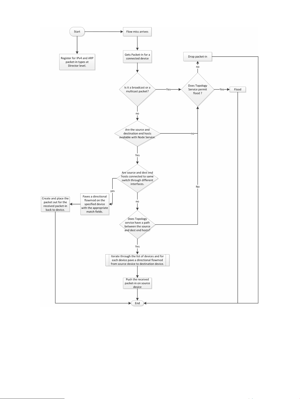
Figure 1 Path daemon flowchart
2.4 Path diagnostics
The path diagnostics application determines and verifies the path taken by a specific packet from
a source host to destination host.
• Evaluates flows configured across the switches in the control domain for diagnosis.
• Creates ‘Observation posts’ on every switch in the path that the packet would take.
• Tallys packet_in messagess from the observation posts to detect where a path is broken.
• Lists neighbors for any given device.
12 Understanding the embedded applications
Page 13

2.5 Topology manager
The topology manager computes the broadcast tree to avoid loops and broadcast storms. On a
given switch it also does the following:
• Provides a list of discovered ports on a given switch.
• Indicates whether a switch port is an edge port (connection point) or part of a link.
• Indicates whether a port is in a blocked or open state by determining whether ingress broadcast
traffic is allowed through the port.
• Verifies whether a path exists between two nodes.
• Enumerates the clusters of OpenFlow-capable switches.
• For a given switch, provides details of the cluster to which it belongs.
• The Topology Manager provides notification to subscribed applications regarding changes
in the broadcast tree and cluster. This enables development of intelligent and proactive
applications that can subscribe to topology change notifications.
2.6 Topology viewer
The topology viewer creates and updates a network graph for visualizing the network the controller
discovers. The Reload button will force a reload of all the nodes and links from the server. For
enhanced performance, the topology view caches nodes and links. In some situations this cache
may get out of sync with the controller. Performing a “Reload” will clear out the topology viewer
cache and regenerate the topology view.
The topology viewer uses the services of the topology manager and link manager.
2.5 Topology manager 13
Page 14
3 Navigating the controller user interface
3.1 Starting the SDN controller console UI
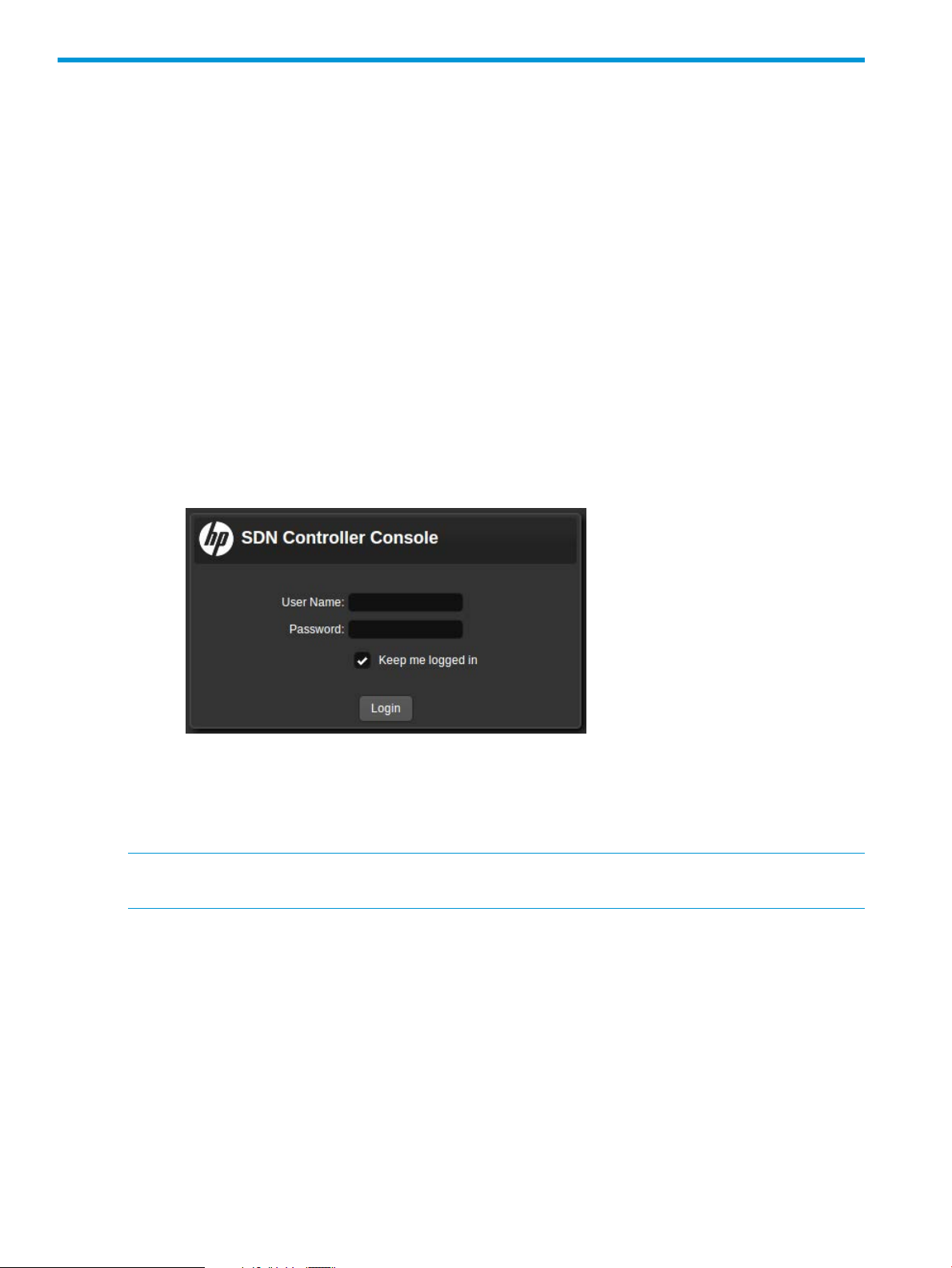
1. Use a supported browser, such as Google Chrome, to access the controller's GUI at the
controller IP address:
GUI
https://controller_ip_addr:8443/sdn/ui
Example
https://192.0.2.1:8443/sdn/ui
2. Enter user name and password credentials, then select Login.
Example
Default user name: sdn
Default password:skyline
3. The main controller screen appears with the Alerts screen displayed. For more information
about the controller console UI, see “About the user interface” (page 14).
3.2 About the user interface
NOTE: The names for common areas, icons, and controls on the UI screen appear after the
image.
14 Navigating the controller user interface
Page 15
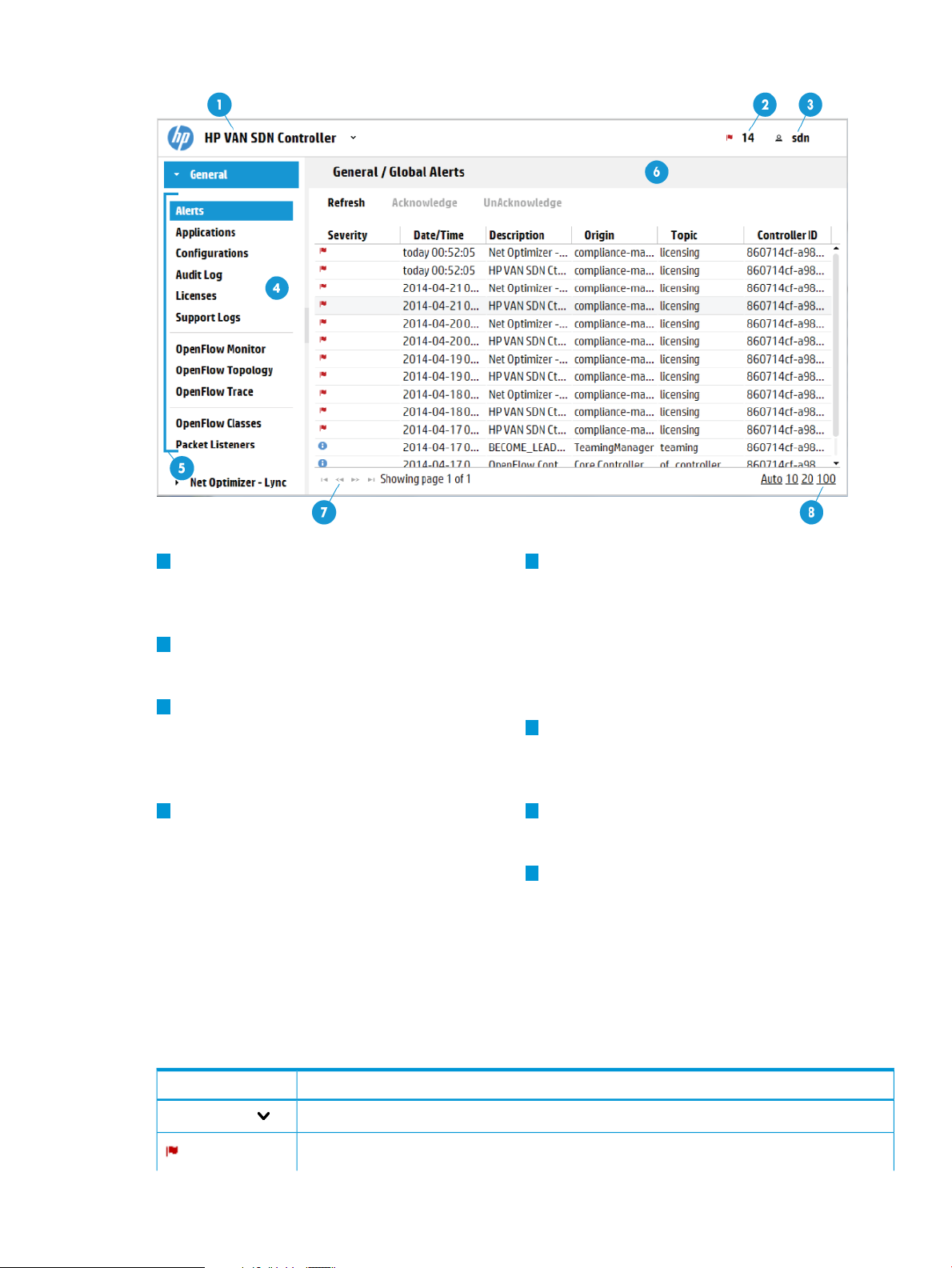
Figure 2 Screen topography
1
Banner: Identifies the user interface. Contains
the alert notification counter and links to the
navigation menu, alert information, and the
SDN User window.
2
Alert notification counter: Displays the current
number of active alerts. Clicking this icon
displays the Alerts as of Today window box.
3
SDN User window: Enables you to log out
of the controller, link to external websites,
identify the version of controller software
currently in use.
4 7
navigation menu: The primary menu for
navigating to controller and application
resources. Contains the controller navigation
tree, labelled General, and can contain
screen (see “Expanding or collapsing the
navigation menu” (page 17)).
5
navigation tree: Used to select the controller
or application screen to display in the details
pane. General is the controller navigation tree.
Navigation trees for installed applications are
displayed below or to the right of the General
navigation tree. In this figure, there are two
navigation trees: General and Net Optimizer
- Lync.
6
Details pane: Displays the detailed interface
for the controller or application resourcechange the theme for the controller, and
selected in the navigation menu. When the
controller starts, it displays the Alerts screen.
Pagination control: Can appear on screens
that have lists of items. Use these controls to
view the listings page by page.
8
Listing control: Can appear on screens that
have lists of items. Use these controls to selectadditional navigation trees for installed
the number of items to display in a singleapplications that integrate with the controller
view. The Auto option displays all items in aUI. Can be displayed as a pane (as shown)
single screen. For listings exceeding the lengthor as a window that overlays the controller
of the screen, you can use the scroll bar on
the right side of the screen.
3.2.1 Banner
SDN Controller
DescriptionScreen component
Expands or collapses the “navigation menu” (page 16) as an overlay window.
Expands or collapses the controller “Alerts as of today” (page 21) window.
3.2 About the user interface 15
Page 16

DescriptionScreen component
The number next to the icon is the “alert notification counter” (page 20), which provides a count
of the current active alerts.
Expands or collapses the “SDN User” (page 17) window.
3.2.2 Changing column widths
To change the column widths, drag the column head borders. For example:
• To narrow the Severity column width, click the border to the left of Date/Time and drag it to
the left.
• To change the width of the navigation menu pane, click and drag the divider between the
menu pane and the details pane.
3.2.3 Changing the background and text colors
The background and text colors are part of the theme of the controller UI. To change the theme:
1. Expand the SDN User window.
2. In Set Theme:, select one of the following options:
• Day
• Night
3.3 Navigation menu
3.3.1 About the navigation menu
The navigation menu is the primary menu for navigating to controller resources. The resources
included with the controller are described in this document. Applications installed on controller
might add resources to this menu.
Displays as a pane or an overlay window
You can display the navigation menu in the following ways:
• As a pane on the left side of the controller browser window.
• As a window that overlays part of the main screen of the controller browser window.
Contains one or more navigation trees
The navigation menu contains the General controller navigation tree and can contain additional
navigation trees for installed applications that integrate with the controller UI.
3.3.2 Navigation menu screen details
DescriptionScreen component
General
Displays the navigation tree for the resources that are provided with the controller. By default,
the General controller navigation tree is expanded and the Alerts screen is selected and
displayed.
To display the screen for another resource, select the resource in the navigation tree.
Expands or collapses the controller navigation menu. If the navigation menu is collapsed, this
icon is located in the left margin of the console screen.
Expands the selected navigation tree. This control is available in the navigation menu for the
General controller navigation tree and for each application that is installed and available through
the controller navigation menu.
16 Navigating the controller user interface
Page 17

DescriptionScreen component
When the navigation menu is displayed as a widow pane on the console, exactly one navigation
tree can be expanded. To collapse a navigation tree for the controller or an application, click
the expand icon for a different navigation tree.
Collapses the navigation window when it is displayed as an overlay window on the console
screen.
3.3.3 Expanding or collapsing the navigation menu
The navigation menu is displayed as a navigation pane by default. You can display the navigation
menu as a pane on the controller screen or as a window that overlays the controller screen.
Expanding or collapsing the navigation menu as a window pane
To expand or collapse the navigation menu as a window pane, click the following icon:
• When the navigation menu is expanded as a window pane, the icon is located on the right
side of the menu.
• When the navigation menu is collapsed, the icon is located in the left margin of the controller
screen.
Expanding or collapsing the navigation menu as an overlay window
To display the navigation menu as an overlay window, from the top banner of the controller screen,
click SDN Controller.
To collapse the navigation window, do one of the following:
• In the window, click
• From the top banner, click SDN Controller.
3.4 SDN User window
The SDN User window displays as an overlay on the controller screen.
3.4 SDN User window 17
Page 18
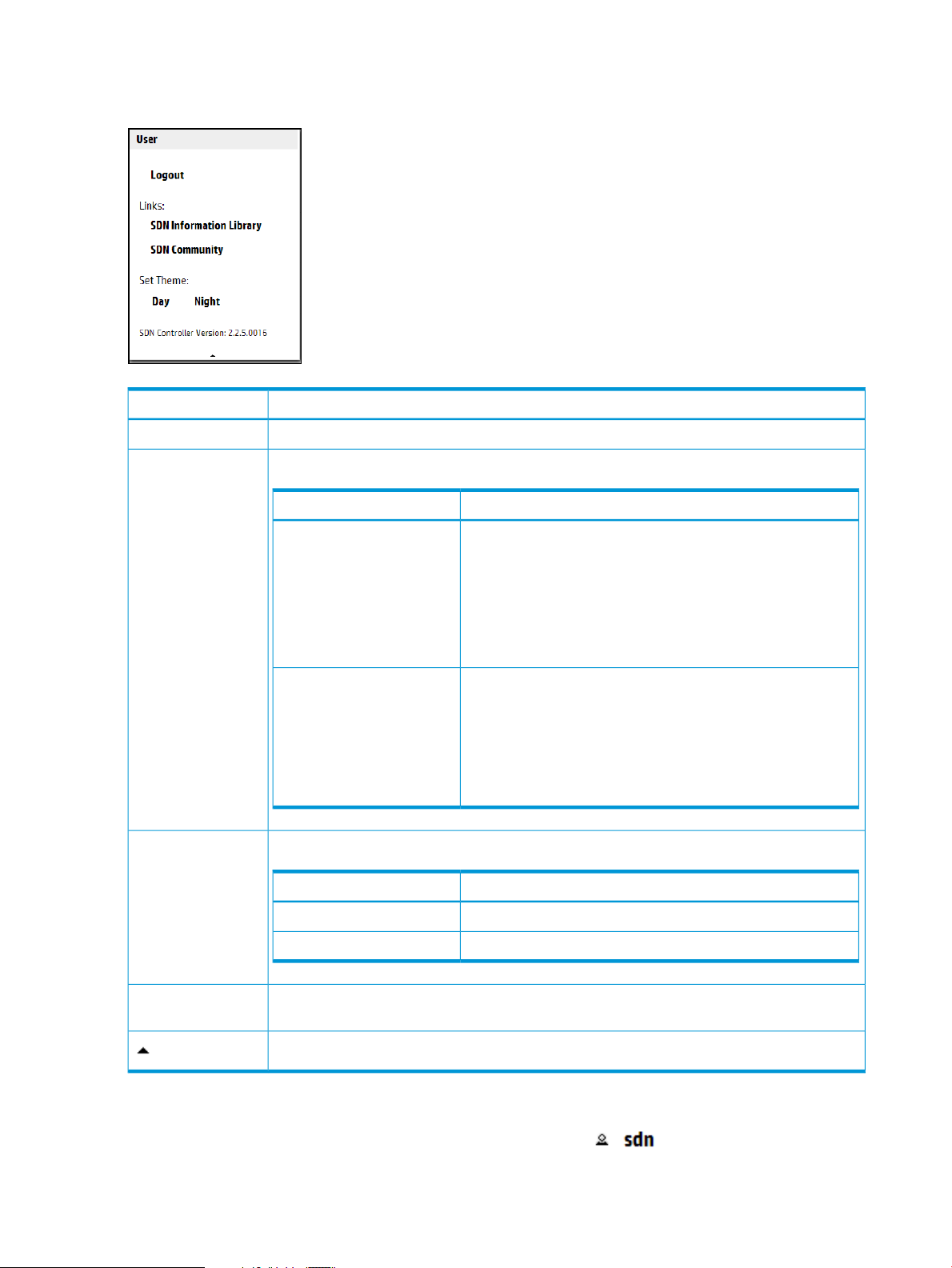
3.4.1 User window screen details
Figure 3 SDN user window
DescriptionScreen component
Logs the user out of the controller.Logout
Links:
Set Theme:
Links to websites outside of the controller:
DescriptionName
SDN Information Library
SDN Community
Changes the theme for the controller UI:
Links to the information library on the HP Software-Defined
Networking website. The HP SDN information library provides
links to the technical documentation for the HP VAN SDN
Controller and the HP SDN applications. The HP
Software-Defined Networking website provides fact sheets, case
studies, white papers, product summaries, technical and business
documentation, and other information to help you identify SDN
solutions for your business needs.
Links to the HP SDN community discussion forum website within
the HP Enterprise Business Community. This site offers resources
such as:
• SDN discussion boards
• SDN development information
• An SDN knowledge base
DescriptionName
When selected, plain text is black and the background is white.Day
Displays the version of the controller software that is running on this system.SDN Controller
Version:
Collapses the window.
3.4.2 Expanding the SDN user window
To expand the SDN User window, from the top banner, click .
18 Navigating the controller user interface
When selected, plain text is white and the background is black.Night
Page 19

3.4.3 Collapsing the SDN user window
To collapse the SDN User window, do one of the following:
• In the SDN User window, click .
• From the top banner, click .
3.4.4 Logging out of the controller
To log out of the controller UI:
• From the SDN User window, select Logout.
3.5 Alerts screen
3.5.1 About alerts
Alerts give notification of events that affect controller operation, and in some cases indicate that
some action is needed to correct a condition.
Alerts and controller teams
When controllers are operating in a team, alerts generated by any team member are visible in
the Alerts screen for all active team members.
Active, unacknowledged alerts
By default, alerts are in an unacknowledged, active state. An alert must be in an active state to
appear in the following places:
• The alert notification counter
• The Alerts as of today window
3.5.2 About alert policies
The values for the AlertManager component keys determine the alert age-out policy. The following
table describes the keys for the AlertManager component
(com.hp.sdn.adm.alert.impl.AlertManager).
trim.alert.age
trim.enabled
trim.frequency
DescriptionKey
Specifies the number of days an alert remains in persistent storage and remains displayed
on the Alerts screen.
Data type A number from 1 through 31
Default value 14
When true, specifies that the controller deletes alerts that have exceeded the
trim.alert.age limit.
Default value true
Specifies how often, in hours, the controller is to delete alerts that have exceeded the
trim.alert.age limit.
Data type A number from 8 through 168
Default value 24
Example Enter 8 to specify that the controller delete aged-out alerts every
eight hours.
3.5 Alerts screen 19
Page 20
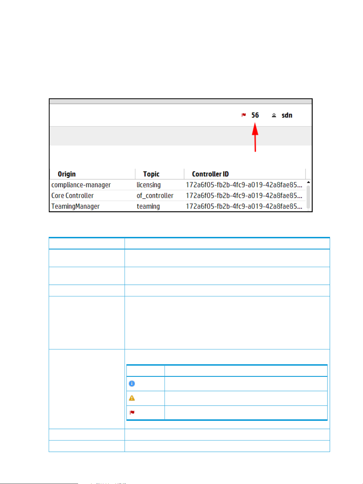
3.5.3 Alert notification counter
The alert notification counter is displayed in top banner and appears on all controller screens. This
counter indicates the number of active alerts:
• The controller increments this counter when each new alert occurs.
• The controller decrements this controller when you acknowledge an alert or when the controller
deletes an alert according to the “alert age-out policy” (page 21) .
Figure 4 Alert notification counter
3.5.4 Alerts screen details
Refresh
Acknowledge
Severity
DescriptionScreen component
Updates the alerts displayed on the screen. The controller does not update the display
as new alerts are generated. Use this action to refresh the display.
Changes the selected alert to an acknowledged state. The controller displays the alert
in gray text. Use this action to indicate that you have read the alert.
Changes the selected alert to an active, unacknowledged state.UnAcknowledge
Indicates the state of the alert:Alert text color
• The controller displays active, unacknowledged alerts the alert in the text color
corresponding to the controller theme. For example, when the controller theme is
daylight, the active alerts appear in black text.
• The controller displays the selected alert in blue text. Click an alert to select it.
• The controller displays acknowledged alerts in gray text.
Indicates the severity of the alert.
DescriptionIcon
Informational
Warning
20 Navigating the controller user interface
Critical
Indicates the date and time the alert was generated.Date/Time
Describes the alert in human readable text.Description
Page 21

DescriptionScreen component
Indicates which component or application generated the alert.Origin
Topic
Controller ID
Indicates of the category for this alert. Multiple origins can contribute alerts to the same
topic.
Identifies the controller that generated the alert. The controller is represented as a
hexadecimal number. When you use controller teaming, this ID enables you to identify
which controller in the team generated the alert.
3.5.5 Viewing the ten most sever recent active alerts
To display a summary of up to 10 alerts ranked by severity (highest to lowest) and then by date
and time (newest to oldest):
• In the top banner, click .
The Alerts as of today window is displayed.
To close the window, do one of the following:
• To close the window and display the Alerts screen, click All.
• At the bottom of the window, click the collapse icon ( ).
• In the top banner, click either the alert counter number or .
3.5.6 Acknowledging an alert
To acknowledge an alert from the Alerts as of today window:
1. Click the alert to select it.
2. Click Acknowledge.
The controller removes the alert from the Alerts as of today window, displays the alert in gray
text on the Alerts screen, and decrements the alert notification counter by one.
To acknowledge an alert from the Alerts screen:
1. Click the alert to select it.
2. Click Acknowledge.
The controller displays the alert in gray text on the Alerts screen, and decrements the alert
notification counter by one.
3.5.7 Deleting an alert
You can acknowledge an individual alert, but you can not clear or delete the alert.
The controller deletes alerts according to the configured alert age-out policy. To configure the
age-out policy, see “Configuring the alert policies” (page 21)
3.5.8 Configuring the alert policies
1. From the Configurations screen, under Component, select the
com.hp.sdn.adm.alert.impl.AlertManager component.
2. Click Modify.
The Modify Configuration dialog box appears.
3. Change the values for the keys. For more information about the keys and values that affect
the alert policy, see “About alert policies” (page 19).
4. Click Apply .
3.5 Alerts screen 21
Page 22

3.6 Applications screen
3.6.1 About the application manager
The Application Manager supports default and add-on network services, and enables installing,
upgrading, enabling (starting), disabling (stopping), and uninstalling SDN applications.
Application manager and controller teams
When controllers are operating in a team, actions performed on one controller are propagated
to the other controllers in the team. Actions you select in the Applications window for one controller,
such as Install, Enable, and Disable, are propagated to the other controllers.
Embedded applications
The following applications are embedded in the controller and are installed when you install the
controller:
• Link Manager
• Node Manager
• Path Daemon
• Path Diagnostics
• Topology Manager
• Topology Viewer
For more information about the embedded applications, see “Understanding the embedded
applications” (page 10).
Prerequisites for installing an application
Any application to be installed on the controller must meet the following requirements:
• It must be in a zip format.
• The zip file must be on the same system as the controller.
• It must contain an application descriptor file containing key value pairs of the attributes
associated with the application, including all mandatory attributes.
Applications you purchase from HP or the HP SDN App Store meet these requirements.
For information about developing applications that meet these requirements, see the HP VAN SDN
Controller Programming Guide.
3.6.2 Applications screen details
DescriptionScreen component
Reloads the view.Refresh
Installs an application on the controller.New
Installs an upgrade to an application that has already been installed on the controller.Upgrade
22 Navigating the controller user interface
Removes an application from the controller.Uninstall
Starts or allows an application to continue operations on the controller.Enable
Stops or prevents an application from operating on the controller.Disable
The name of the applicationName
Page 23

DescriptionScreen component
The version number of the applicationVersion
State
The most common states are listed in the following table.
DescriptionState
The application has been started and is servicing requests.ACTIVE
STAGED
DISABLED
A new application has been downloaded to the controller and is
ready to be installed.
The application has been stopped. Applications in this state are
not restarted when the controller restarts.
3.6.3 Obtaining applications from the HP SDN AppStore
When the AppStore becomes available you will be able to purchase and download applications
for your controller. Until the AppStore becomes available, the following buttons do not access
AppStore features:
• Log in to view applications…
• Launch AppStore
3.6.4 Adding or upgrading an application
Any application in the proper format can be added to the controller (see “About the application
manager” (page 22)).
After you complete this procedure:
• The application is started and in an ACTIVE state.
• If the controller is in a controller team, the controller propagates the application to all the
controllers in the team automatically.
Use this procedure to install either a new application or a new version of an existing application
on the controller using the UI.
1. Do one of the following:
• To install a new application, click New.
• To upgrade to a new version of an existing application, select the application from the
Name list and click Upgrade.
2. Click Browse to navigate to the location of the application zip file and select the file.
3. Click Upload to upload the file.
Wait for Completed to appear. For example:
3.6 Applications screen 23
Page 24
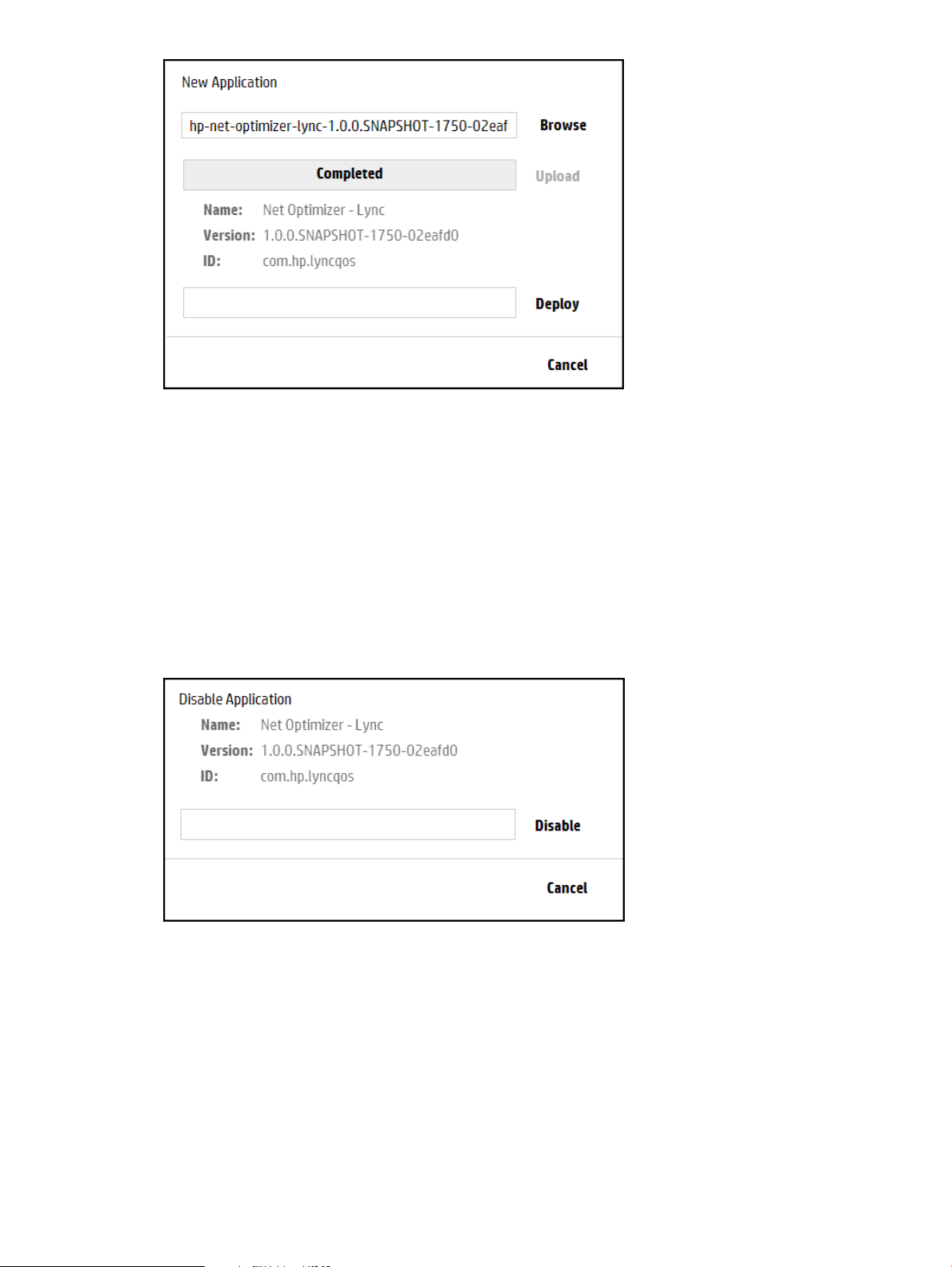
4. Click Deploy.
The new application then appears by name on the Applications screen as ACTIVE.
3.6.5 Disabling (stopping) or enabling (starting) an application
This procedure temporarily stops an active application from servicing requests, but retains the
application on the system. The application remains present on the system and can be restarted
when needed. (The application does not automatically restart when the controller restarts.)
Procedure 1 Disabling an application using the UI
1. In the Applications screen, select the application you want to stop.
2. Click Disable to display the Disable Application dialog box.
3. In the Disable Application dialog box, click Disable.
The Disable Application dialog box closes and the application state is changed to DISABLED.
Procedure 2 Enabling an application using the UI
1. In the Applications screen, select the application you want to enable.
2. Click Enable to display the Enable Application dialog box.
24 Navigating the controller user interface
Page 25
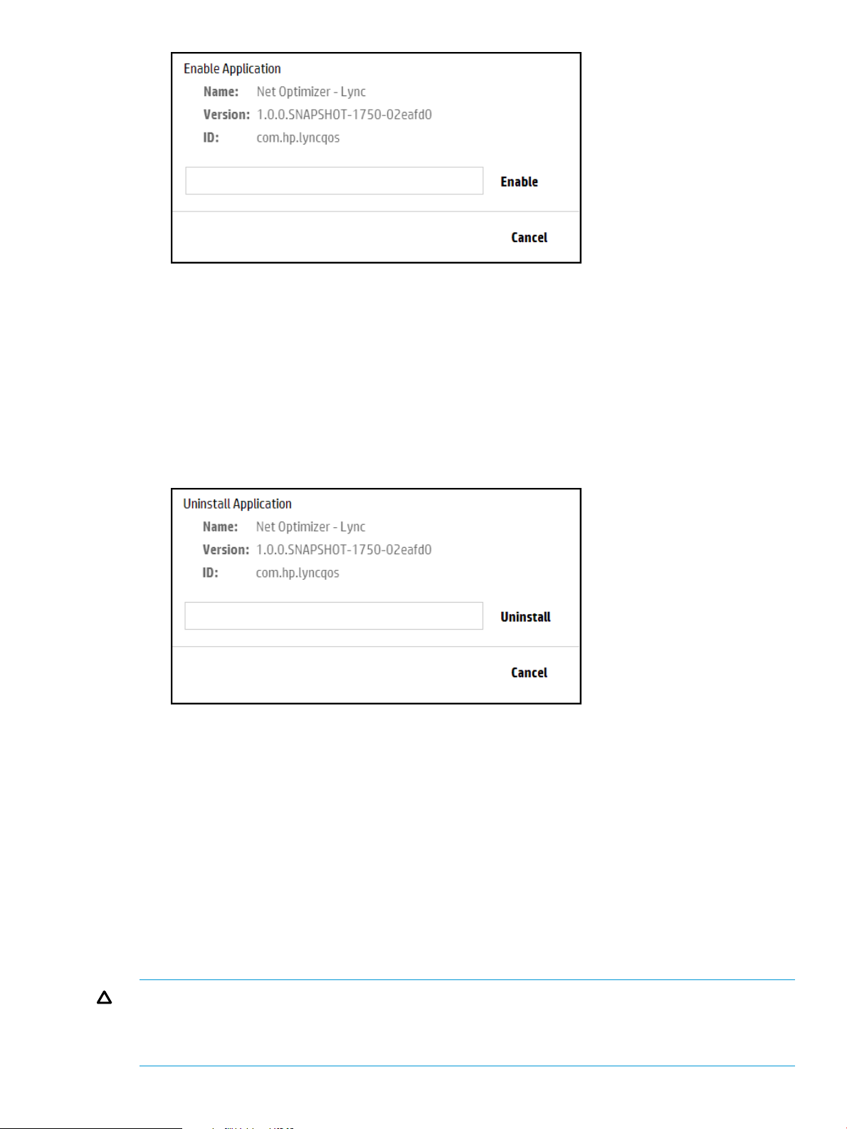
3. Click Enable button to activate the application. The application starts or resumes operation
and the application state is changed to ACTIVE.
3.6.6 Uninstalling an application
This procedure completely removes an application from the controller. To later restore the removed
application, see Adding or upgrading an application.
Use the following procedure to uninstall an application using the UI.
1. In the Applications screen, select the application you want to uninstall.
2. Click Uninstall.
3. Click the Uninstall button to remove (delete) the application.
3.7 Configurations screen
The Configurations screen enables access to the configurable components in the controller.
3.7.1 About the configurable components
The configuration components are used to manage the controller and application features. The
base set of controller components support the applications that are embedded in the controller.
Adding or removing an SDN application might add or remove additional configuration component.
However, direct addition or removal of configuration components is not supported.
Each configuration component contains one or more component keys, each of which identify a
configurable property of the component.
CAUTION: Inappropriate changes to key values can result in severely degraded system
performance. For this reason, HP strongly recommends that managing the default key values be
done only by experienced network administrators and programmers who have a strong
understanding of SDN controller systems.
3.7 Configurations screen 25
Page 26

Configurations and controller teams
When controllers are operating in a team, configuration changes on one active controller propagate
to the other active controllers in the team.
3.7.1.1 About component keys
Each configuration component contains one or more component keys, each of which identify a
configurable property of the component.
CAUTION: Inappropriate changes to key values can result in severely degraded system
performance. For this reason, HP strongly recommends that managing the default key values be
done only by experienced network administrators and programmers who have a strong
understanding of SDN controller systems.
Information about each component key includes the current value, the default value, and a brief
description. Where applicable, the range of suggested values is also included. Component key
information
Information about the component keys are available from:
• The Configuration screen of the controller UI.
• The controller Configs REST API.
3.7.2 Summary of configurable controller components
3.7.2.1 AdminREST Component
Component name
com.hp.sdn.misc.AdminRESTComponent
Description
The AdminRestComponent provides parameters for internal communication between SDN
components and the Admin REST API of the controller.
Component keys
Information about the configurable component keys, including descriptions, current values, suggested
ranges, and default values are available from:
• The Configuration screen of the controller UI.
• The controller Configs REST API.
3.7.2.2 Alert manager
Component name
com.hp.sdn.adm.alert.impl.AlertManager
Description
The AlertManager controls the quantity of alert data present on the system by periodically checking
for alert data to be deleted based on the configured age-out policy.
Component keys
Information about the configurable component keys, including descriptions, current values, suggested
ranges, and default values are available from:
• The Configuration screen of the controller UI.
• The controller Configs REST API.
26 Navigating the controller user interface
Page 27

3.7.2.3 Alert post manager
Component name
com.hp.sdn.api.impl.AlertPostManager
Description
The AlertPostManager uses the HTTP(s) protocol to send alert data as a a JSON string to registered
alert topic listeners.
Component keys
Information about the configurable component keys, including descriptions, current values, suggested
ranges, and default values are available from:
• The Configuration screen of the controller UI.
• The controller Configs REST API.
3.7.2.4 Audit log manager
Component name
com.hp.sdn.adm.auditlog.impl.AuditLogManager
Description
The AuditLogManager controls the quantity of audit log data present on the system by periodically
checking for audit log data to be deleted based on the configured age-out policy. For more
information about audit log policies, see “Configuring audit log policies” (page 33).
Component keys
Information about the configurable component keys, including descriptions, current values, suggested
ranges, and default values are available from:
• The Configuration screen of the controller UI.
• The controller Configs REST API.
3.7.2.5 Authentication manager
Component name
com.hp.sdn.adm.auth.impl.AuthenticationManager
Description
The AuthenticationManager provides for the authentication of external users to the SDN Controller.
Component keys
Information about the configurable component keys, including descriptions, current values, suggested
ranges, and default values are available from:
• The Configuration screen of the controller UI.
• The controller Configs REST API.
3.7.2.6 Controller manager
Component name
com.hp.sdn.ctl.of.impl.ControllerManager
Description
The ControllerManager provides parameters used in the implementation of the OpenFlow protocol.
3.7 Configurations screen 27
Page 28

Component keys
Information about the configurable component keys, including descriptions, current values, suggested
ranges, and default values are available from:
• The Configuration screen of the controller UI.
• The controller Configs REST API.
3.7.2.7 Link manager
Component name
com.hp.sdn.ctl.linkdisco.impl.LinkManager
Description
The LinkManager provides parameters used for discovering links between network elements.
Component keys
Information about the configurable component keys, including descriptions, current values, suggested
ranges, and default values are available from:
• The Configuration screen of the controller UI.
• The controller Configs REST API.
3.7.2.8 Log manager
Component name
com.hp.sdn.adm.log.impl.LogManager
Description
The LogManager controls the number of log message rows displayed in the Support Logs display.
Component keys
Information about the configurable component keys, including descriptions, current values, suggested
ranges, and default values are available from:
• The Configuration screen of the controller UI.
• The controller Configs REST API.
3.7.2.9 Metric manager component
Component name
com.hp.sdn.adm.metric.impl.MetricManagerComponent
Description
The MetricManagerComponent determines how measurement data is maintained by the controller.
The controller includes a metering framework that internal components and installed applications
can use to collect various types of data. (Data can be persisted on the controller from sources
external to the controller.) Any metric created with the framework may optionally be persisted over
time or directed to the controller JMX facility for viewing. Data persisted over time can be viewed
using the controller REST API, while data sent to JMX can be viewed using JConsole or another
JMX client. The MetricManagerComponent permits configuring default values for certain aspects
of the metering framework operation, such as how long the controller should retain persisted data,
at what time of day persisted data that is too old should be trimmed, and how often persisted
metric values should be saved to disk. (This value can be overridden for any metric when the metric
is created).
28 Navigating the controller user interface
Page 29

Component keys
Information about the configurable component keys, including descriptions, current values, suggested
ranges, and default values are available from:
• The Configuration screen of the controller UI.
• The controller Configs REST API.
3.7.2.10 Node manager
Component name
com.hp.sdn.ctl.nodemgr.impl.NodeManager
Description
The NodeManager provides parameters for discovering and maintaining end host locations in the
network.
Component keys
Information about the configurable component keys, including descriptions, current values, suggested
ranges, and default values are available from:
• The Configuration screen of the controller UI.
• The controller Configs REST API.
3.7.2.11 Path diagnostic manager
Component name
com.hp.sdn.ctl.diag.impl.PathDiagnosticManager
Description
The PathDiagnosticManager defines the lifetime of the diagnostics flows used for tracing a path.
Component keys
Information about the configurable component keys, including descriptions, current values, suggested
ranges, and default values are available from:
• The Configuration screen of the controller UI.
• The controller Configs REST API.
3.7.2.12 Path daemon
Component name
com.hp.sdn.ctl.path.impl.PathDaemon
Description
The PathDaemon provides parameters used by the path daemon to perform Layer-2 forwarding.
See also “Understanding the embedded applications” (page 10).
Component keys
Information about the configurable component keys, including descriptions, current values, suggested
ranges, and default values are available from:
• The Configuration screen of the controller UI.
• The controller Configs REST API.
3.7.2.13 RestPerf provider
Component name
com.hp.sdn.rs.RestPerfProvider
3.7 Configurations screen 29
Page 30

Description
The RestPerfProvider reports performance data for the REST API.
Component keys
Information about the configurable component keys, including descriptions, current values, suggested
ranges, and default values are available from:
• The Configuration screen of the controller UI.
• The controller Configs REST API.
3.7.2.14 Role assert manager
Component name
com.hp.sdn.adm.role.impl.RoleAssertManager
Description
The RoleAssertManager provides parameters the controller uses for determining role message
transmit retries and response periods.
Component keys
Information about the configurable component keys, including descriptions, current values, suggested
ranges, and default values are available from:
• The Configuration screen of the controller UI.
• The controller Configs REST API.
3.7.2.15 Service REST component
Component name
com.hp.sdn.misc.ServiceRestComponent
Description
The ServiceRestComponent provides parameters for internal communication between SDN
components and the SDN controller Northbound REST API.
Component keys
Information about the configurable component keys, including descriptions, current values, suggested
ranges, and default values are available from:
• The Configuration screen of the controller UI.
• The controller Configs REST API.
3.7.2.16 System watchdog manager
Component name
com.hp.sdn.adm.system.impl.SystemWatchdogManager
Description
The SystemWatchdogManager provides heartbeat status checking between SDN controllers that
are running as part of a team.
3.7.2.17 Trace manager
Component name
com.hp.sdn.ctl.of.impl.TraceManager
Description
The TraceManager specifies how long a trace is to run after it starts.
30 Navigating the controller user interface
Page 31

Component keys
Information about the configurable component keys, including descriptions, current values, suggested
ranges, and default values are available from:
• The Configuration screen of the controller UI.
• The controller Configs REST API.
3.7.2.18 End-Host discovery via ARP protocol
Component name
com.hp.sdn.disco.of.node.impl.OfArpDiscoveryComponent
Description
OpenFlow end-host discovery via the ARP protocol.
3.7.2.19 End-Host discovery via DHCP protocol
Component name
com.hp.sdn.disco.of.node.impl.OfDhcpDiscoveryComponent
Description
OpenFlow end-host discovery via the DHCP protocol
3.7.2.20 End-Host discovery via IP Protocol
Component name
com.hp.sdn.disco.of.node.impl.OfIpDiscoveryComponent
Description
OpenFlow end-host discovery via the IP protocol.
3.7.3 Configurations screen details
DescriptionScreen component
Opens the Modify Configuration dialog box for the selected component.Modify
The name of the component.Component
Click to display the key and value information for the component.expand icon
The display for each key includes the current value, the default value, and a brief description.
Where applicable, the range of suggested values is also included.
Click to hide the key and value information for the component.collapse icon
3.7.4 Modifying a component configuration
1. Select the component you want to modify.
2. Click Modify.
The Modify Configuration dialog box is displayed. For example:
3.7 Configurations screen 31
Page 32

3. Enter new values for each of the keys you want to modify.
4. Do one of the following:
• To save your changes and close the dialog box, click Apply.
• To close the dialog box without saving changes, click Cancel.
3.8 Audit log screen
3.8.1 About the audit Log
The audit log is available through both the controller GUI and the REST API, and records events
related to activities, operations, and configuration changes initiated by an authorized user. This
includes activities such as:
• Installing an application (or starting, stopping, uninstalling an application)
• Modification to a components configuration
• Installing a license
• Forming a controller team
Audit log and controller teams
When controllers are operating in a team, the audit log shows events for all controllers in the team.
3.8.1.1 About audit log policies
The values for the AuditLogManager component keys determine the alert age-out policies. The
following table describes the keys for the AuditLogManager component
(com.hp.sdn.adm.auditlog.impl.AuditLogManager).
365trim.auditlog.age
truetrim.enabled true Specifies that the controller deletes log entries that have
24trim.frequency
3.8.2 Audit Log screen details
DescriptionScreen component
DescriptionDefault ValueKey
Specifies the number of days to retain a log entry. Use this key to implement
your record retention policy.
Data type A number from 31 through 1825.
exceeded the trim.auditlog.age limit.
false Specifies that the controller does not delete log entries that
have exceeded the trim.auditlog.age limit.
Specifies how often, in hours, the controller is to delete log entries that have
exceeded the trim.alert.age limit.
Data type A number from 8 through 168
Example Enter 24 to specify that the controller delete aged-out log
entries every 24 hours (once per day).
Refresh
32 Navigating the controller user interface
Updates the log entries displayed on the screen. The controller does not update the
display as new entries are generated. Use this action to refresh the display.
The user that performed the operation that triggered the log entryUser
A time stamp (in UTC format) indicating when the controller created the log entry.Occurred
The type of activity that triggered the creation of the log entry.Activity
The application or controller component that generated the log entry.Origin
Page 33

DescriptionScreen component
Detailed information about the log entry.Data
Controller ID
For example, the audit log displays software license and teaming activity:
Figure 5 Audit Log screen example with licensing and teaming activity
3.8.3 Deleting a log entry
You cannot delete or modify a log entry. The controller deletes entries according to the configured
audit log policies. To configure the audit log policies, see “Configuring audit log policies” (page 33)
A hexadecimal number that identifies controller that generated the log entry. When
you use controller teaming, this ID enables you to identify which controller in the team
generated the alert.
3.8.4 Configuring audit log policies
1. From the Configurations screen, under Component, select the
com.hp.sdn.adm.auditlog.impl.AuditLogManager component.
2. Click Modify.
The Modify Configuration dialog box appears.
3. Change the values for the keys. For information about the keys and values for this component,
see “About audit log policies” (page 32).
4. Click Apply .
3.8.5 Exporting and archiving audit log data
To retain log records for longer than the trim.auditlog.age limit, you must export the audit
log from the controller to a file before the trim.auditlog.age limit is reached. Exporting audit
log data does not remove it from persistent storage.
To export the audit log, you must use the REST APIs.
3.9 Licenses screen
The Licenses screen displays the controller Install ID, activates new licenses, and deactivates installed
licenses (for transfer to another installation).
3.9.1 About licenses
Licenses are required for the controller and for any installed applications. For information about
licenses, see “License Registration and Activation” (page 52).
3.9 Licenses screen 33
Page 34

3.9.2 Licenses screen details
DescriptionScreen component
Updates the screen with the latest license information.Refresh
Adds and activates the specified license key on this controller.Add
Deactivates the selected license.Deactivate
Contains the installation identifier for this controller.Install ID
Serial#
Product
Licensed For
Qty
Type
Status
Expire By
Uninstall Key
3.9.3 Installing, activating, uninstalling, or transferring licenses
For information about installing, activating, uninstalling, and transferring licenses, see “License
Registration and Activation” (page 52).
3.10 Support logs screen
3.10.1 About support logs
The support logs maintain an internal record of events of interest from the operations of an active
SDN controller. This information is the type of data a support engineer would request when
troubleshooting an SDN installation.
Support logs and controller teams
In a controller team environment:
• Each controller maintains its own support logs.
• Changing the log.queue.size on any controller propagates to all active controllers in the
team.
• The Export action gathers the set of support log file data from all active controllers in the team,
and stores the data as a single compressed archive.
Multiple support logs
The controller allows up to five support logs; one active and four in storage:
• When the current log reaches 10MB, the controller copies the log to storage and starts a new
log.
• When the space allocated for all support logs is full, the controller purges the oldest log file
to make room for continued logging operation.
• Support logs are stored in the controller /var/log/sdn/virgo/logs directory.
• Support logs can be exported to a file (see “Exporting the support logs ” (page 36))
34 Navigating the controller user interface
Page 35

3.10.2 Support logs screen details
DescriptionScreen component
Refresh
Export
Level
Displays a listing of the most recent log messages, as determined by the currently
configured queue size. For example, with a queue size of 100, Refresh lists the 100
most recent log messages.
Gathers the set of support log file data from the standalone controller or all active
controllers in the team, and stores the data as a single compressed archive.
The severity level for the entry. Levels are:
DescriptionValue
Recorded in support logsERROR
WARN
INFO
DEBUG
TRACE
In the default configuration, the ERROR, WARN, and INFO levels are recorded in the
Support Logs. DEBUG and TRACE are verbose logging that are used in troubleshooting
situations that may involve support engineering.
The logging level for a component that is writing to the support log can be dynamically
changed using the Virgo Administrator console. For example, DEBUG level logging
can be enabled for just the NodeManager configuration component.
Logger
Thread
Message
Detailed information about the log entry.Data
Controller ID
A hexadecimal number that identifies controller that generated the log entry. When
you use controller teaming, this ID enables you to identify which controller in the team
generated the alert.
3.10.3 Configuring the support log queue size
The default queue size is 100 lines. To configure a different queue size, change the value for the
max.display.rows key of the LogManager component.
1. From the Configurations screen, under Component, select the
com.hp.sdn.adm.log.impl.LogManager component.
2. Click Modify.
The Modify Configuration dialog box appears.
3. Change the value for the max.display.rows key.
4. Click Apply.
3.10.4 Configure signed application zip file verification
By default, the SDN Controller does verify that an application zip file has been signed from a
trusted source as defined in your /opt/sdn/admin/sdnjar_trust.jks truststore. To enable or disable
checking that all application zip files downloaded through the application manager are signed
and are from a trusted source, you must change the value for the “verifyZips” key.
3.10 Support logs screen 35
Page 36

1. From the Configurations screen, under Component, select the
com.hp.sdn.adm.mgr.impl.AppManager component.
2. Click Modify.
The Modify Configuration dialog box appears.
3. Change the “verifyZips” key value to “False” to enable checking.
4. Click Apply.
NOTE: To download an application with this check enabled, the public certificate used to
recognize the signed zip file must be installed in the sdnjar_trust.jks truststore. See “Adding
certificates to the jar-signing truststore ” (page 68).
3.10.5 Exporting the support logs
The Export operation:
1. Gathers the set of support log file data from the controller, or in a team environment, all active
controllers in the team, and stores the data as a single compressed archive file:
sdn-all-logs.zip
2. Downloads the archive file from the controller to the default download directory specified by
your browser. For example, in Ubuntu installations, this is usually the Downloads directory.
1. Click Export.
The following menu appears in the lower-left corner of the controller console:
Figure 6 Completion of the export operation
2. When the download completes, you can either resume interaction with the controller or examine
the log by selecting an item from the menu, such as:
• Open a window showing the new log zip file.
• Set the default operation to always open the directory containing the log zip file.
• Show the log zip file in the default directory for receiving downloads.
NOTE: The actions resulting from these choices depend on the browser and operating system,
not on the controller.
3.11 OpenFlow monitor screen
When the controller is active in an OpenFlow domain, the OpenFlow Monitor enables tracking of
switch traffic summaries, packet traffic per port, and applied flow rules for switches detected in
the controller domain. The main display lists the Data Path IDs for the active switches and the
options for viewing traffic information.
3.11.1 About the OpenFlow monitor
When the controller is active in an OpenFlow domain, the OpenFlow Monitor enables tracking of
switch traffic summaries, packet traffic per port, and applied flow rules for switches detected in
the controller domain. The main display lists the Data Path IDs for the active switches and the
options for viewing traffic information.
36 Navigating the controller user interface
Page 37

3.11.2 OpenFlow monitor screen details
3.11.2.1 Main display
DescriptionScreen component
Updates the information displayed on the screen.Refresh
Displays the “Summary for data path view” (page 37) for the selected data path.Summary
Displays the “Ports for data path display” (page 37) for the selected data path.Ports
Displays the “Flows for data path display” (page 38) for the selected data path.Flows
Displays the Groups view for the selected data path.Groups
Data Path ID
Identifies a detected OpenFlow switch. The OpenFlow data path identification for
each detected OpenFlow switch. This ID also appears in the representation of the
switch in the OpenFlow Topology screen.
Identifies the IP address associated with an OpenFlow data path instance.IP Address
The version of OpenFlow in use with the corresponding data path.Negotiated Version
3.11.2.2 Summary for data path view
This view includes the following related to the selected device:
• Manufacturer
• Hardware and software version
• Serial number and device description
• Device identification (Data Path ID) and IP address
• TCP port on the device
• Negotiated OpenFlow version (latest OpenFlow version common to both the controller and
the switch)
• OpenFlow table and buffer information
• OpenFlow capabilities on the device
Figure 7 Summary for data path view
3.11.2.3 Ports for data path display
This view includes information on the ports used for OpenFlow traffic on the selected device.
3.11 OpenFlow monitor screen 37
Page 38

Figure 8 Ports view for a specific OpenFlow device
3.11.2.4 Flows for data path display
This view includes the current flows on the selected OpenFlow device. For a given flow, traffic
meeting the requirements specified in the "Matches" field is directed as specified in the
corresponding "Actions/Instructions" field.
Figure 9 Flows view for a specific OpenFlow device
NOTE: The Table ID applies to OpenFlow 1.3 and greater, but not to OpenFlow 1.0.
3.11.3 Discovering changes in the topopology
Click Refresh to update the display for topology changes, such as a newly discovered OpenFlow
device or the loss of a device that has failed.
3.11.4 Viewing information about a specific device
To view information about a specific device, click the Data Path ID for that device and then click
the button for the view you want to display.
For a graphical view of Data Path ID assignments to individual OpenFlow switches, see OpenFlow
topology screen.
38 Navigating the controller user interface
Page 39

3.12 OpenFlow topology screen
The OpenFlow screen displays a topology of discovered switches and end nodes in the controller
domain. The viewer creates and updates a graph of the network, and computes the broadcast tree
to avoid loops and broadcast storms. The shortest path is computed using Dijkstra’s graph search
algorithm. The viewer:
• Displays a topology of discovered switches and end nodes.
• Identifies the ports discovered on a given switch.
• Identifies the shortest path between two nodes.
• Provides node identification options (MAC or IP address label).
• Provides a view of switch port identifiers, active flow rules, and a tool for testing flow rule
options.
CAUTION: Do not allow a loop between the OpenFlow and non-OpenFlow portions of your
network unless you enable Spanning Tree Protocol on the non OpenFlow devices operating in the
network
NOTE: In a topology where two or more controlled switches connect to the same uncontrolled
switch, the controller will not learn the location of hosts connected to the uncontrolled switch.
3.12.1 Displaying the network toplogy
The OpenFlow Topology screen includes the switches and end-nodes in the controller domain.
Figure 10 Topology viewer
3.12 OpenFlow topology screen 39
Page 40

Figure 11 Default topology view with switch and end-nodes
3.12.1.1 Configuring how the OpenFlow network topology is displayed
Both of the following tools provide control for different parts of the OpenFlow Topology display:
• The icon for a list of keyboard shortcuts you can use to change the display.
• The View menu for:
Port labels on switches◦
◦ Switch datapath details
◦ A tool for selecting Packet selection criteria
End nodes can be labelled with one of the following:
• No Label (default)
• IP Address
• MAC Address
For example, to show the IP addresses of the end-nodes in the OpenFlow topology, click anywhere
in the topology display, then press N. The end-node IP addresses appear as labels in the topology
diagram:
40 Navigating the controller user interface
Page 41

Figure 12 End-node IP address labeling
Press N again to display the end-node MAC addresses as labels in the topology diagram:
Figure 13 End-node MAC addresses as labels
Press N again to return to the unlabeled end-node view.
Switches are always labelled with their data path ID. You can also:
• Add port labels to the links between switches and between switches and end nodes.
• Identify flow details and options. (See “Identifying flow details and flow options” (page 43).)
3.12 OpenFlow topology screen 41
Page 42

• "Pin" the switches and end nodes in the topology display.
• "Collapse" the topology display to show only the number of end nodes connected to each
switch, instead of showing all end nodes (the default) which can present a cluttered display
where a large number of end nodes are connected to the OpenFlow switches.
In the topology display:
• To display or remove port numbers for the links, press P or select View→Ports.
• To pin or unpin the switches and end nodes, press X or select View→Pin All.
• To hide or show all switch end nodes, pressG or select View→Collapse All.
Figure 14 Switch ports labels
Figure 15 Collapse All option
The number appearing under the Data Path ID for a switch in the topology diagram indicates the
number of detected end nodes connected to the switch.
To toggle between hiding or showing all switch end nodes, click anywhere in the topology display
and then press G.
To toggle between hiding or showing the end nodes for a particular switch, select the switch and
then press C.
3.12.1.2 Viewing the shortest path between two nodes
1. Select the source node and press S or click Src.
42 Navigating the controller user interface
Page 43

2. Select the destination node and press D or click Dst.
The controller displays the path between the two nodes as a red line (see Figure 16 (page 43)).
Figure 16 Locating the shortest path between two nodes
To exchange source and destination nodes, press A.
To clear the source and destination flags, press Z.
3.12.1.3 Identifying flow details and flow options
• Do one of the following:
• Select Shortest Path→Follow Flow
• Select a switch in the shortest path and press I, then select the switch again and press T.
The Switch Details window displays the flow details and the Abstract Packet window displays
selection criteria for packets moving between the Source-Destination node pair.
3.12 OpenFlow topology screen 43
Page 44

Figure 17 Flow details for the selected source-destination end nodes
Using the fields in the Abstract Packet window, search for flow rules for packets having criteria
dictating a path other than shortest path, for example, by entering port 80 for HTTP packets.
Figure 18 Searching for flows for specific packet types
3.13 OpenFlow trace display
This troubleshooting tool logs OpenFlow conversations captured in messages to and from the
controller and the OpenFlow devices it manages.
You can export the captured messages in the trace log to a CSV (Comma-Separated Values) file
that can be opened by applications such as Excel that are designed to accommodate this file type.
This enables you to create a filter to display only the messages from the specific data paths you
want to examine.
3.13.1 About the trace log
The number of events that can be held in the trace log is limited by system memory. For this reason,
HP recommends that you export to a remote storage location any trace log content you want to
retain, and to clear the controller trace log whenever its content is not needed on the controller
itself.
44 Navigating the controller user interface
Page 45

3.13.2 OpenFlow trace display details
DescriptionScreen component
Starts trace logging.
In the default configuration, the trace stops after ten seconds have passed. (To change the
trace interval, see “Changing the OpenFlow trace interval ” (page 48).)
Stops trace logging before the end of the configured trace interval.
Trace logging stops automatically at the end of the configured trace interval.
Multiple consecutive traces can be held in the trace log. To add additional trace results, start
another trace.
Clears (resets) the current trace log.
To preserve the contents of the trace log before clearing it, see “Exporting the OpenFlow
trace log” (page 46).
Displays details of the selected trace event.
Export
Copies the trace log into a CSV (comma-separated values) file. See see “Exporting the
OpenFlow trace log” (page 46).
The time the message event was generated.Time
The event type. For example:Event
CkPt Indicates a check point in the trace log, such as the starting or stopping of a trace
operation.
Rx Indicates an OpenFlow message recieved by the controller (from a datapath).
Tx Indicates an OpenFlow message sent from the controller (to a datapath).
The DPID (data path ID) of the data path associated with the event.DPID
The trace message.Message
3.13.3 Starting, stopping, or clearing OpenFlow trace
Use the buttons above the Time field to control trace operations (see “OpenFlow trace display
details” (page 45)).
3.13.4 Displaying trace event details
1. Select the event you want to examine.
2. Click . Alternatively, double-click on the event.
The Event Detail dialog box is displayed.
3.13 OpenFlow trace display 45
Page 46

Figure 19 Displaying event details
3. To close the Event Detail window, click Close.
3.13.5 Exporting the OpenFlow trace log
Exporting an OpenFlow Trace Log places the trace content in a CSV file that is stored in the default
downloads folder specified in your web browser settings.
For more information about CSV files, see RFC 4180.
NOTE: This section shows how to export and access OpenFlow Trace Log files using Google
Chrome. You may experience different results than shown here, depending on your web browser
and its configuration.
1. Click Export. This action places the trace log contents into a CSV file in the default downloads
folder in the system on which the controller is running. Check your web browser for an
indication that the file has been created.
2. To display and filter the CSV file content, see “Filtering the OpenFlow trace log in a CSV file”
(page 47).
46 Navigating the controller user interface
Page 47

3.13.6 Filtering the OpenFlow trace log in a CSV file
1. Open the CSV file in the default folder. For example, using Google Chrome, open the menu
adjacent to the file name (of-trace.csv) and select Show in folder.
Figure 20 Accessing the stored CSV file
In the resulting folder listing, locate the of-trace.csv file and open it using an application,
such as Excel, that enables you to read the log messages and configure a filter. For example,
to investigate the messages collected for data path 00.00.00.00.00.00.00.02:
2. Select the DPID (Data Path ID) column.
Figure 21 DPID column
3. Set the filter.
Figure 22 Setting the filter
4. Apply the filter by checking the box for data path 00.00.00.00.00.00.00.02.
3.13 OpenFlow trace display 47
Page 48

Figure 23 Applying the filter
5. In the resulting display, only the data filtered to data path 00:00:00:00:00:00:00:02 appears.
Figure 24 Filtered trace log
3.13.7 Changing the OpenFlow trace interval
The default trace interval is ten seconds. To change the interval:
1. From the navigation menu, select Configurations.
2. Open the com.hp.sdn.ctl.of.impl.TraceManager component.
3. Click Modify.
48 Navigating the controller user interface
Page 49

4. In the Value field, enter the desired duration in seconds for active trace recording.
5. Click Apply to set the new time span for active trace recording, and return to the OpenFlow
Trace view.
3.14 OpenFlow classes display
The OpenFlow classes display shows the OpenFlow classes that applications have registered with
the controller. For more information about OpenFlow classes, see “About OpenFlow classes”
(page 49).
3.14.1 About OpenFlow classes
When multiple applications share the same resource—the flow tables of OpenFlow switches—how
can their priorities relative to each other be determined and how can their actions be coordinated?
If flow table modification priorities are directly coded into each application, applications can end
up directly competing with other applications for the highest priorities, which can result in conflicts
in general network traffic control and unintended results when you implement a solution that has
multiple SDN applications attempting to act on the same packets. In addition, many environments
make it difficult to trace the origin of flow modification requests installed in switches.
The HP VAN SDN Controller uses OpenFlow classes to dynamically manage the priorities of the
OpenFlow rules being deployed to the network, thus enabling applications to execute their business
logic in a more orderly fashion.
1. For each class of flow modification message the application can send, the application must
register an OpenFlow class with the controller. The OpenFlow class must specify the types of
match fields, types of actions, and (optionally) the relative position (higher than or lower than)
for this class with respect to other flow classes.
2. The controller adds a unique base cookie to be used with each future flow modification to be
validated against this OpenFlow class, and assigns an actual priority for the OpenFlow class.
This actual priority is based on the logical priorities of all of the OpenFlow classes of all the
applications that are registered with the controller.
3. When the application sends a flow modification message, it must set the match and action to
be the same fields as specified in the OpenFlow class and, instead of providing an actual
priority, the application sets the logical priority as assigned by the flow class, and a cookie
that is derived from the base cookie of the OpenFlow class.
4. Before sending the flow table modification message to the switch, the controller evaluates the
requested flow modification against the registered OpenFlow classes and replaces the logical
priority provided by the application with an actual priority.
In addition to enabling the controller to manage priorities for multiple applications, OpenFlow
classes enable the controller to validate flow modifications an application makes against a set of
expected flow modification requests. This capability means that the behavior of an application
must match the intent that the application disclosed when it registered with the controller:
• The flow match must contain exactly the fields and field types that were disclosed when the
application registered with the controller. The controller validates field types but not field value.
• The action or instruction must fall into the category that was disclosed during registration.
An action is classified into one of the following categories:
FORWARD
DROP
PROCESS
STEAL
COPY
• The upper 16 bits of the flow modification cookie must match the upper 16 bits of the base
cookie that was issued during registration.
3.14 OpenFlow classes display 49
Page 50

3.14.2 Controller enforcement levels for OpenFlow classes
The following table lists the enforcement levels that the controller can use for applications that send
flows to switches.
DescriptionEnforcement level
none
weak
strict
The controller does not manage flow modification priorities or validate flow modification
requests:
• Applications that do not register OpenFlow classes with the controller are permitted to
send flow modifications to switches.
• The controller does not validate flow modifications, even for applications that register
OpenFlow classes with the controller.
• The controller does not replace logical priorities with actual priorities for flow modification
requests from any applications.
(Default) The controller manages flow modification priorities and validates flow modification
requests for applications that register OpenFlow classes:
• Applications that do not register OpenFlow classes with the controller are permitted to
send flow modifications to switches.
• The controller validates flow modifications from registered applications against the
OpenFlow classes that are registered.
• The controller replaces logical priorities with actual priorities for registered applications
only.
The controller manages all flow modification priorities and validates all flow modification
requests:
• Applications that do not register OpenFlow classes with the controller are not permitted
to send flow modifications to switches.
• The controller validates all flow modifications against the OpenFlow classes that are
registered.
• The controller replaces logical priorities with actual priorities for all applications.
3.14.3 OpenFlow classes display details
The OpenFlow classes screen displays the OpenFlow classes that are currently registered with the
controller:
DescriptionScreen component
Refreshes the list.Refresh
Flow Class ID
Cookie
Match Fields
Actions
Description
The symbolic name for the flow class. The prefix identifies the application that registered
the class; the suffix uniquely identifies the class.
The actual priority the controller assigns to flows of this class.Priority
The base value of the cookie assigned to this OpenFlow class. The application that
registered this class must use this base cookie when constructing flows that belong to
this class.
The types of match fields that are expected to be specified in flows that belong to this
class.
The general category of the action or instruction a flow that belongs to this class is
expected to include. For a list of categories, see “About OpenFlow classes” (page 49).
Short description of what the OpenFlow class does. The application describes the
OpenFlow class when it registers the class with the controller.
50 Navigating the controller user interface
Page 51

3.14.4 Changing the enforcement levels for OpenFlow classes
To change the enforcement level the controller applies to applications sending flows to switches,
change the value for the flow.mod.enforcement key of the
com.hp.sdn.ctl.of.impl.ControllerManager configuration component.
For more information about configuration components, see “Configurations screen” (page 25).
For information about the enforcement levels the controller can apply, see “Controller enforcement
levels for OpenFlow classes” (page 50).
3.15 Packet listeners display
The controller applications (and SDN applications) register packet listeners with the controller. The
order of processing an incoming packet is determined by the roles (Advisor, then Director, then
Observer), and then altitudes within a role (in decreasing value, with 0 the lowest altitude). An
incoming packet (OpenFlow Packet-In message) is wrapped in a Message Context (which also
holds a Packet-Out reply) which is passed to each packet listener in turn.
3.15.1 Packet listeners display details
The packet listeners screen displays the packet listeners that are currently running on the controller.
DescriptionScreen component
Refreshes the information on the screen.Refresh
Role
Altitude
# Samples
The role of the packet listener. Roles are one of the following:
DescriptionRole
ADVISOR
DIRECTOR
OBSERVER
Packets are given to packet listeners with role of ADVISOR first, DIRECTOR second,
and OBSERVER third. Every packet listener is guaranteed to see the packet-in message.
Depending on the action taken by higher altitude Directors, a lower altitude Director
may be too late to influence the packet processing.
The weight or priority this packet listener should have relative to other packet listeners
that have the same role. The controller gives packet listeners with higher numbers
priority over packet listeners with lower numbers.
The average time, in milliseconds, that the packet listener spent processing a packet.Average (ms)
The number of packets processed by that packet listener since the packet listener
registered.
Examines the incoming packet. Might add processing hints to
the message context, but does not modify the packet out
message.
Processes the packet. Might add actions or instructions to the
packet-out message. Can instruct the controller to block the
packet, or to send the packet out.
A passive observer who might examine the incoming packet
and any packet-out response.
3.15 Packet listeners display 51
Page 52

4 License Registration and Activation
4.1 Overview
NOTE: SDN applications can require licenses that are separate from the licenses for the controller.
Typically, you must have both a license for the controller and a license for each application. For
HP SDN applications, you register the license, obtain the license key, and activate the license on
the controller using the same methods you use to register and activate controller licenses. For
information about obtaining license keys for an application, see the administrator guide for the
application.
4.1.1 License registration and activation process
NOTE: To maintain license registration and activation across an HP VAN SDN Controller software
update, refer to “License types, usage, and expiration” (page 52).
After you have downloaded and installed the controller software, as described in the HP VAN
SDN Controller Installation Guide, you can begin the license registration and activation process.
The basic steps are:
1. Preparing for license registration and activation:
a. Verify registration prerequisites
b. Identify the Install ID displayed in the controller GUI.
2. Registering and activating a license:
a. Use the HP My Networking portal to enter your order information, register a license, and
obtain a license key
b. Use the license key to activate the license on the controller
3. Managing licenses:
• Transfer licenses:
1. Uninstall licenses to prepare for transfer
2. Transfer licenses to a new platform
3. Use new license keys to activate the licenses on the target controller.
4.1.2 License types, usage, and expiration
The following licenses are available for the HP VAN SDN Controller:
• High Availability “Add Controller” license (HP VAN SDN Ctrl HA E-LTU)—Enables the controller
to form a team for increased availability. The following guidelines apply:
• The minimum number of team members for an HP VAN SDN Controller team is three.◦
◦ When forming a team, only one HP VAN SDN Controller base license is required, along
with at least two High Availability licenses, all on the same Master controller. Once a
team is formed, Add Nodes licenses can be added to the team leader for increased
support. In addition, you must:
– Use non-previously licensed controller installations to form the team.
– Use a new hardware platform (or Virtual Machine) with a new installation of the HP
VAN SDN Controller.
– Run the same software version on all controllers.
• Application Licenses—Refer to the administrator guide for the specific application.
52 License Registration and Activation
Page 53

4.2 Preparing for license registration
4.2.1 Verifying registration prerequisites
Before beginning the license registration and activation process, be sure you have:
• Obtained an HP My Networking portal user account.
• Obtained the order number or product registration ID, and e-mail address from your HP VAN
SDN Controller license order confirmation.
• Installed the HP VAN SDN Controller software and have the controller running, as described
in the HP VAN SDN Controller Installation Guide.
4.2.2 Identifying the install ID
Each controller installation generates a unique Install ID that is used for licensing activities.
To view the Install ID using the UI, select Licences from the navigation menu. In the Licenses screen,
the Install ID appears before the list licenses.
4.3 Registering and activating a license
Using your Install ID, you must now register your license on the My Networking portal. Doing this
results in a license key, which enables you to activate the license on the controller.
NOTE: If you are registering licenses in addition to the base controller license, HP recommends
you do so in the following order:
1. Register the base controller license.
2. Register any Add Nodes licenses, and then activate the last license key generated.
3. Register any High Availability licenses, and then activate the last license key generated.
4. Register any application licenses you have acquired.
4.4 Registering your license and obtaining a license key
To register your license and obtain a license key:
1. Log on to the My Networking portal at http://www.hp.com/networking/mynetworking.
2. Select My Licenses.
Locate the Order number or Registration ID field, as shown in Figure 25 (page 53).
Figure 25 Entering an order number or registration ID
4.2 Preparing for license registration 53
Page 54

3. Enter your order number or registration ID in the field provided (above), and then click Next.
• If you enter a registration ID, go to “step 5” (page 54).
• If you enter an order number, the Email field appears, as shown in Figure 26.
Figure 26 Entering an e-mail address
4. In the Email field, enter either the “Ship to” or “Sold to” e-mail address listed in your sales
order confirmation, and then click Next.
A license selection screen appears, as shown in Figure 27.
Figure 27 Selecting licenses
5. Select the license type, enter the quantity to be registered to your Install ID, and then click
Next.
54 License Registration and Activation
Page 55

NOTE:
• For an HP VAN SDN Ctrl Base SW w/ 50–node E-LTU license, the quantity must be 1.
• For HP VAN SDN Ctrl 50–node E-LTU or HP VAN SDN Ctrl HA E-LTU licenses, quantity is
the number of licenses to be installed with a single Install ID.
• For information on using this process for an application license, see the administrator
guide for that application.
The registration details screen appears, as shown in Figure 28.
Figure 28 Entering the install ID
6. In the Install ID field, enter your Install ID number. (See “Identifying the install ID” (page 53).
7. Optional: Enter a Friendly name and Customer notes for this license.
8. Click Next.
The end user software license agreement screen appears, as shown in Figure 29.
4.4 Registering your license and obtaining a license key 55
Page 56

Figure 29 Accepting the license agreement
9. To continue after reading the license agreement, select I accept all of the above terms, and
then click Finish.
The confirmation screen appears, as shown in Figure 30.
Figure 30 Reviewing your registration
10. Review your license registration details, and record the License key listed.
11. Optional: To download the license key file, click Save as, and then save it to your local hard
drive.
56 License Registration and Activation
Page 57

12. Optional: To e-mail the registration details:
a. Enter one or more e-mail addresses, separated by a comma or semi-colon in the field
provided.
b. Optional: Enter Comments about this license.
c. Click Send email.
13. Optional: If you want to register additional licenses for this order:
a. Click Register more for this order to return to the license selection screen shown in
Figure 27.
b. Repeat steps “5” (page 54) through 13 until you have registered all licenses.
To view your license information:
1. Click on My Licenses on the My Networking portal.
Figure 31 My Licenses tab
2. Click on View Licenses to see a screen similar to the following.
Figure 32 Viewing licenses
3. To view the information for the license you just loaded, click on the Select button for that
license. You will then see a screen similar to the following:
Figure 33.
4.4 Registering your license and obtaining a license key 57
Page 58

Figure 33 Viewing your license and other information
Record the license key in the above screen for use when you activate the license on the controller.
4.5 Activating a license on the controller
To activate a license on the controller, you must add the license key. If the controller has no licenses
listed, enter the license key for the HP VAN SDN Ctrl Base SW w/50–node E-LTU before you add
any other license keys.
Use the following procedure to add and activate a license using the controller UI.
1. From the navigation menu, select Licenses.
2. On the Licenses screen, enter the license key you acquired in “Registering your license and
obtaining a license key” (page 53) in the text box next to the Add button.
Entering the key in the field enables the Add button.
58 License Registration and Activation
Page 59

Figure 34 Enter the License Key
3. To activate the license, click on the Add button shown in Figure 34 (page 59).
The active license is displayed in the table below the Install ID and the Add button is greyed
out:
Figure 35 Active License Displayed on License screen
4.6 Managing licenses
4.6.1 Transferring licenses
You can transfer a license from one controller to another. To do so, you must first uninstall all
licenses from the controller.
NOTE: Keeping a license on one controller while transferring one or more other licenses from
the same controller to another controller is not permitted.
When upgrading to version 2.3, no special effort is required to preserve the licenses. Note that
the license transfer mechanism is only required when you want to switch the SDN Controller currently
running hardware. You must install the SDN Controller on the new hardware and transfer the
licenses to that new hardware before retiring the old hardware.
Before you transfer licenses
Before you transfer licenses, you must first:
• Uninstall all licenses, as described in “Uninstalling licenses to prepare for transfer” (page 60).
• Obtain an Install ID for each destination controller, as described in “Identifying the install ID”
(page 53).
4.6 Managing licenses 59
Page 60

4.6.1.1 Uninstalling licenses to prepare for transfer
When you deactivate a license, the controller generates an Uninstall Key for that license, which
you will need when you transfer the license. Be prepared to record the Uninstall Key for each
license you deactivate. The Uninstall Key is a long text string. For example:
AE2RCLT7CJMDI-MAGAQHS2NBTOB-6VM4QKEQ4HAEZ-3AY4QELRPG4AA-3EMHQELRPGAYQ
To uninstall a license using the controller UI, use the following procedure.
1. From the navigation menu, select Licenses.
2. Select the license to uninstall.
3. Click Deactivate.
Click OK when the deactivation prompt appears:
4. Record the Uninstall key appearing in the Uninstall Key field for that license.
5. Repeat the preceding steps for each of the remaining licenses on the controller.
4.6.1.2 Transferring licenses
After you have uninstalled all of the licenses for a controller, you can transfer them to another
controller.
To transfer licenses:
1. Log on to the My Networking portal at http://www.hp.com/networking/mynetworking.
2. From the My Licenses section, select Transfer licenses to a new platform.
3. In the Search field, enter the Install ID for the controller from which you uninstalled the license,
and then click Search.
The transfer license screen displays a list of associated licenses, as shown in Figure 36.
Figure 36 Selecting licenses to transfer
4. Click the Select icon next to the license to be transferred.
The license details screen appears, as shown in Figure 37.
60 License Registration and Activation
Page 61

Figure 37 Reviewing details before transfer
5. Verify that this is the license you want to transfer, and then click Next.
The target install ID screen appears (Figure 38).
Figure 38 Entering target install and uninstall IDs
6. In the screen in Figure 38, do the following:
1. In the Target Install ID field, enter the Install ID of the controller to which you want to
transfer the license.
2. In each Uninstall field, enter a license uninstall key. (For more on acquiring uninstall keys,
see Section 4.6.1.1.)
4.6 Managing licenses 61
Page 62

NOTE: In order for the transfer process to succeed, you must enter an Uninstall value
for every registered license.
3. Click on the Transfer button in the lower-right corner of the screen.
New license registration information displays on the license transfer confirmation screen and
license details screen, as shown in Figure 39.
Figure 39 Viewing license transfer confirmation and details screens
7. Review the confirmation screen details.
8. For each license you are transferring, record the new license key so that it will be available
when you add and activate the license on the new controller.
9. Optional: To e-mail transferred license details:
a. Enter one or more e-mail addresses, separated by a comma or semi-colon in the field
provided.
b. Optional: Enter Comments about this license transfer.
c. Click Send email.
The license screen displays the status of the original licenses as Transferred, and the new Install
IDs as Active, as shown in Figure 40.
Figure 40 Review transferred license status screens
To register the transferred licenses on the new controller, see “Activating a license on the controller”
(page 58).
62 License Registration and Activation
Page 63

5 SDN Controller authentication
5.1 SDN Controller security guidelines
The HP VAN SDN controller communicates with different components, both internal and external
to the controller, via secure channels. This section documents these channels, their defaults, and
how to configure them in a deployment environment.
5.2 SDN Controller authentication
The SDN Controller identifies itself via Public-Key Infrastructure (PKI) for its communication with
external subsystems and other controllers. It uses a Java keystore and truststore to keep its private
key and public key respectively. For REST APIs, the controller does not rely on the truststore to
establish trust. Instead, it uses token authentication to authenticate the client. The client must present
a valid token via the X-Auth-Header to authenticate itself with the controller. Token authentication
is discussed more under “SDN Controller keystore and truststore locations and passwords ”
(page 64).
The controller ships with a self-signed certificate. Therefore, it is recommended that the self-signed
certificate be replaced by a certificate signed by a reputable Certificate Authority (CA). Also, the
default password for the keystore and truststore should be changed as well.
5.3 Creating SDN Controller keystore and truststore
1. Login to the system running the SDN Controller and stop the controller.
2. As the SDN user (i.e. sudo - sdn), do the following:
3. Back up your default /opt/sdn/admin/keystore and /opt/sdn/admin/truststore
to a safe location.
4. Create a new keystore using the following commands:
cd /opt/sdn/admin
rm keystore truststore
keytool -genkey -alias serverKey -keyalg rsa -keysize 2048 -keystore
keystore
You must specify a fully qualified domain for your server for the "first and last name" question
as some CAs, such as VeriSign, expect it.
5. Generate a CSR (Certificate Signing Request) for signing:
keytool -keystore keystore -certreq -alias serverKey -keyalg rsa
-file sdn-server.csr
6. Send the sdn-server.csr to a CA to be signed.
The CA will authenticate you and return a signed certificate and its CA certificate chain. We
assume the signed certificate from the CA is named signed.cer and the CA's certificate is
root.cer. If root.cer is from your own internal CA, then you need to import root.cer
into your browser as an authority.
7. Import the signed root certificate into your keystores:
keytool -importcert -trustcacerts -keystore keystore -file root.cer
-alias CARoot
keytool -importcert -trustcacerts -keystore truststore -file root.cer
-alias CARoot
5.1 SDN Controller security guidelines 63
Page 64

8. Replace your self-signed certificate in your serverKey entry with the signed certificate from
your CA (signed.cer).
keytool -importcert -keystore keystore -file signed.cer -alias
serverKey
9. If you are operating a team of controllers in your environment, turn off self-signing for
inter-controller communication:
Under /opt/sdn/virgo/repository/usr, change the "selfsigned" value to false for the following
component:
com.hp.sdn.misc.ServiceRestComponent.properties
10. If you set up a different password than the default "skyline" password for your keystore, you
will need to edit /opt/sdn/virgo/configuration/tomcat-server.xml and change
the keystorePass value in the <Connector port="8443"…> tag to the new keystore
password.
11. Start the controller. Continue to the next section if you are using a different keystore and
truststore password than the default "skyline" password.
5.4 SDN Controller keystore and truststore locations and passwords
The SDN Controller keystore and truststore are referenced by several components, and thus need
to be updated for these components:
• com.hp.sdn.api.impl.AlertPostManager
• com.hp.sdn.misc.AdminRestComponent
• com.hp.sdn.misc.ServiceRestComponent
To change these configuration of these components:
1. From the navigation menu, select Configurations.
2. Select one of the three components listed above.
3. Select Modify.
4. Repeat for the other two components.
64 SDN Controller authentication
Page 65

Figure 41 Components that reference controller keystore and truststore
The values for keystore and keystore.password contain the keystore location and encrypted keystore
password respectively. The values for truststore and truststore.password contain the truststore
location and encrypted truststore password respectively.
5.5 Configuration encryption
Sensitive information such as tokens and passwords are stored encrypted on the SDN Controller.
However, to encrypt and decrypt these properties, the controller requires a master key that is
passed into the controller upstart script via an environment variable. To change the default master
key (recommended):
1. First, stop these services:
sudo service sdnc stop
sudo service sdna stop
2. Then change the default master key:
sudo /opt/sdn/admin/sdnpass old_master_key new_master_key
5.6 Openflow Controller TLS
The Openflow controller component relies on PKI to establish mutual trust (2-way SSL) between
itself and the Openflow switches that it manages. It is recommended that the Openflow keystore
and truststore used for Openflow switch communication be separate from the SDN Controller’s
keystore and truststore used for north-bound communication.
5.6.1 Creating Openflow Controller keystore and truststore
The process for creating the Openflow keystore and truststore is similar to the steps outlined under
“Creating SDN Controller keystore and truststore” (page 63), and therefore is not repeated here.
The store names for both the Openflow keystore/truststore and the SDN Controller’s
keystore/truststore should be different. Please note that both the Controller and Device certificates
5.5 Configuration encryption 65
Page 66

must be signed by the same CA, so that the TLS connection will be established. See your switch’s
manual for information about configuring TLS on your switch.
5.6.2 Openflow Controller keystore and truststore locations and passwords
The Openflow Controller’s configurations for keystore/truststore are located in the
com.hp.sdn.ctl.of.impl.ControllerManager configuration. The keystore and keystore.password
properties capture the location of the keystore and the password of the keystore respectively.
Similarly, the truststore and truststore.password capture the location of the truststore and the
password of the truststore respectively.
Figure 42 Components that reference OpenFlow keystore and truststore
A controller restart is required if these configurations are changed.
5.7 REST authentication
The SDN Controller relies on token-based authentication to authenticate its REST APIs. In other
words, all REST APIs except the /auth and /rsdoc APIs require an authentication token embedded
in an "X-Auth-Token" header to be included with each REST request. The /auth API allows you to
obtain a token, while the /rsdoc API provides live REST API documentation information about the
controller’s REST API. The next section describes how to obtain a token from the /auth API.
66 SDN Controller authentication
Page 67

5.7.1 Openstack Keystone
The SDN Controller uses Openstack Keystone as an identity management for managing users,
generating tokens, as well as token validation. Upon installation, the SDN Controller creates the
following users and roles:
• User: sdn – This is the primary user that operates different SDN REST and UI operations. The
sdn user has roles sdn-user and sdn-admin.
• User: rsdoc – This is the primary user that is associated with API documentation operations.
The rsdoc user has sdn-user role.
• The Keystone version in use is based on the Folsom release. If a later Keystone version is in
use:
◦ Ensure that it supports the Keystone v2.0 REST API.
◦ Configure the token provider to use the UUID token (instead of PKI tokens). This is
configurable via /etc/keystone/keystone.conf.
◦ For keystone configuration details, see:
http://docs.openstack.org/developer/keystone/configuration.html
The SDN Controller currently does not enforce role-based permissions (RBAC); however, it may
do so in the future. Also, applications installed on the SDN Controller may choose to enforce RBAC
per their security requirements.
To authenticate, one needs to present username/password to the /auth API as below (using curl
as an example):
curl -sk -H 'Content-Type:application/json' -d
'{"login":{"user":"sdn","password":"password","domain":"sdn"}}'
https://<controller-ip>:8443/sdn/v2.0/auth
CAUTION: Credential information (user name, password, domain, and authentication tokens)
used in cURL commands may be saved in the command history. For security reasons, HP recommends
that you disable command history prior to executing commands containing credential information.
The above call returns this example JSON data structure that includes the authentication token,
which, by default, expires in 24 hours:
{
"record": {
"domainId": "62e312edff47413fad7e1d7fa6ac7bc7",
"domainName": "sdn",
"expiration": 1377917359000,
"expirationDate": "2013-08-30 19-49-19 -0700",
"token": "54a6f80a9ae243db89bfa05de4ced51d",
"userId": "bca3dea8a28b457e99e899ae16b79634",
"userName": "sdn"
}
}
CAUTION: Please guard this token information, as it can be used as an API key to gain access
to your SDN Controller REST APIs.
To gain access to the REST API, include the token in the X-Auth-Token header as in the following
curl example:
curl -sk -H "X-Auth-Token:54a6f80a9ae243db89bfa05de4ced51d"
https://controller-ip:8443/sdn/v2.0/systems
5.7 REST authentication 67
Page 68

One can continue using the same token for different SDN Controller APIs within the default 24-hour
period since token creation. If desired, one can change this default 24-hour timeout in the /etc/
keystone/keystone.conf file. (See the OpenStack Keystone Administration Guide for more
information). The CachedTokenTTL value under the configuration properties
com.hp.sdn.adm.auth.impl.AuthenticationManager needs to match the timeout set by
Keystone as well to allow efficient caching of tokens.
5.7.2 Service and admin tokens
The Service token is used for internal communication between controllers and is not exposed to
the user. Likewise, the Admin token is used for the communication between the controller and the
Keystone server and is not exposed to the user.
That said, the values for these tokens can be changed via the UI under the Configurations for
AuthenticationManager. Note that for the Service token, all controllers in a team must have the
same Service token to communicate successfully. Likewise, for the Admin token, both the controller
token value and the Openstack Keystone "admin_token" in /etc/keystone/keystone.conf must
match for authentication to work.
5.8 Controller code verification
All controller code is signed by HP. Validating the certificate via jarsigner should return an HP
X.509 certificate similar to the following:
X.509, CN=Hewlett-Packard, OU=HPGlobal, OU=Digital ID Class 3 - Java
Object Signing, O=Hewlett-Packard, L=Andover, ST=Massachusetts, C=US
[certificate is valid from 11/14/12 4:00 PM to 11/15/14 3:59 PM]
X.509, CN=VeriSign Class 3 Code Signing 2010 CA, OU=Terms of use at
https://www.verisign.com/rpa (c)10, OU=VeriSign Trust Network,
O="VeriSign, Inc.", C=US
[certificate is valid from 2/7/10 4:00 PM to 2/7/20 3:59 PM]
[CertPath not validated: null]
If a controller jar or war file is tampered with, the jar verification fails, and the container does not
start up.
If an application is not signed by HP, or has its certificate trusted by the controller (see section
below), the application is not allowed to run on the controller.
5.8.1 Adding certificates to the jar-signing truststore
To deploy other signed applications onto the controller, use the Java keytool to import the public
certificate that was used to sign the application jars and/or zips into the controller jar-signing
truststore (/opt/sdn/admin/sdnjar_trust.jks):
keytool -importcert -keystore /opt/sdn/admin/sdnjar_trust.jks -file
signed_app.cer -alias mysignedcert
The controller needs to be restarted for the new truststore to take effect.
5.8.2 Running the SDN Controller Without Jar-Signing Validation
The SDN Controller enforces jar-signing validation by default. For an experimental/development
environment where unsigned applications need to be deployed, jar-signing validation can be
turned off altogether:
1. Use the following command to stop the SDN Controller:
sudo service sdnc stop
68 SDN Controller authentication
Page 69

2. Modify the /opt/sdn/virgo/bin/dmk.sh script to add the following option to the list of
JMX_OPTS:
-Dsdn.signedJar=none
For example:
cd $KERNEL_HOME; exec $JAVA_EXECUTABLE \
$JAVA_OPTS \
$DEBUG_OPTS \
$JMX_OPTS \
-XX:+HeapDumpOnOutOfMemoryError \
-XX:ErrorFile=$KERNEL_HOME/serviceability/error.log \
-XX:HeapDumpPath=$KERNEL_HOME/serviceability/heap_dump.hprof \
-Dsdn.signedJar=none \
-Djava.security.auth.login.config=$AUTH_LOGIN \
-Dorg.eclipse.virgo.kernel.authentication.file=$AUTH_FILE \
3. Start the SDN Controller:
sudo service sdnc start
To enable jar-signing validation, remove the line containing the -Dsdn.signedJar=none option
from the /opt/sdn/virgo/bin/dmk.sh script and restart the controller.
5.9 Revoking Trust
5.9.1 Revoking trust via truststore
The controller components rely on the public certificates in the respective truststore to establish trust
with a given identity. Therefore, revoking trust from a client with a given public certificate amounts
to removing its certificate from the respective truststore. To remove a given certificate from the
truststore:
• List the certificates in your truststore:
keytool –list –v -keystore truststore [-storepass password]
• Delete certificate from truststore:
keytool –delete –alias cert-aliastruststore
5.9.2 Revoking trust via CRL
For the controller’s REST API, a CRL (Certificate Revocation List) may also be specified to allow
blacklisting of certain clients. This is done by modifying the /opt/sdn/virgo/configuration/
tomcat-server.xml file to include the CRL file location in the SSL connector:
<Connector port="8443" protocol="HTTP/1.1" SSLEnabled="true"
maxThreads="150" scheme="https" secure="true"
clientAuth="false" sslProtocol="TLS"
keystoreFile="../admin/keystore"
keystorePass="skyline"
crlFile="location_of_CRL file"/>
For the change to take effect, restart the controller.
5.10 SDN administrative REST API
The main SDN Controller daemon (SDNC) is accompanied by an ancillary daemon process (sdna),
which runs under user sdnadmin in order to grant it access to some elevated privileges.
The administrative REST API can be used to securely perform various management functions in a
privileged context. It would be undesirable for the main SDN Controller process to possess those
privileges as it may be hosting execution of third-party code.
5.9 Revoking Trust 69
Page 70

The SDN Administrator daemon can be accessed via the REST API vi HTTPS on port 8081. The
access is secured through either token-based authentication or basic authentication, against the
locally running keystone server, which is the same as the main SDN Controller REST API.
The following set of features are accessible through the administrative REST API:
• SDN Controller daemon (sdnc) stop/start/restart
• Adding/removing the team leader IP alias (required only when in team mode)
• Downloading the ZIP bundle of log files
• Uploading upgrade Debian bundles and installing/removing Debian packages
• Uploading upgrade ZIP bundles and executing upgrade commands
• System reboot
The install process adds a number of sudoers entries for the sdnadmin user. These are as follows:
• /sbin/ifconfig
• /sbin/reboot
• /usr/bin/service
• /usr/bin/at
• /usr/bin/dpkg
All, or any, of the above entries can be blocked or removed from the sudoers configuration. The
/sbin/ifconfig entry is only required when running in teamed mode. Otherwise the controller
cannot migrate the team IP address from node to node as team leader changes.
The sdna daemon can be completely disabled by stopping the daemon by using the sudo service
sdna stop command and then removing the /etc/init/sdna.conf file.
5.11 Virgo admin UI access
The Virgo admin UI is configured to only be accessible via a local host. Access to this UI can be
made via http://localhost:8080/admin. This should not be used under normal circumstances, but
can be useful for debugging purposes.
To change the credentials of this console, get root console access to the machine(s) running the
HP VAN SDN Controller and edit the following file:
/opt/sdn/virgo/configuration/org.eclipse.virgo.kernel.users.properties
This file includes the following two entries:
user.admin=sdn
role.admin=admin
where role.admin defines the user and user.admin defines the password. This file needs to
be owned by user:sdn, group:sdn. Changes to this file require a restart of the controller to
recognize the new credentials.
To disable access to the Virgo Admin UI, either remove the following file or move it to a safe
location outside the pickup directory.
5.12 Virgo console access
This allows Virgo administrative access via ssh/telnet. This service is disabled by default. The
following file configures these properties and requires the controller to restart to recognize the new
settings:
/opt/sdn/virgo/pickup/
org.eclipse.virgo.management.console_3.6.2.RELEASE.jar
70 SDN Controller authentication
Page 71

5.13 JMX console
The JMX console is only enabled for local access. This is used by the controller for metering and
can also be used for debugging.
To enable JMX console remote access, edit /opt/sdn/virgo/bin/dmk.sh. The following line
determines whether JMX allows remote access or not:
-Dcom.sun.management.jmxremote.local.only=true \
Any changes to this file require a controller restart to recognize the change.
5.14 Security practices
5.14.1 Security procedure
1. Update the following passwords:
• Keystore
• Truststore
• Jarsigning
• Admin Token
• Service Token
• Authentication Manager
2. Log into http://<cont_IP>:/8443/sdu/ui as the SDN user.
3. Select Configurations.
4. Select the component com.hp.sdn.ctl.of.impl.AuthenticationManager.
5. Select Modify.
6. Set the AdminToken to the newly chosen Keystore (authentication) admin token.
7. Set the ServiceToken to the newly chosen internal communication secret.
8. Set the KeystorePass to the value that you will be using to secure the SSL Keystore.
9. Set the TruststorePass to the value that you will be using to secure the SSL Truststore.
10. Update the Keystore Admin Token in the file etc/keystore/keystore.conf.
Change the Admin Token from admin_token=ADMIN to
admin_token=<AdminTokenSetInControllerConf>.
11. Update the Keystore password to match the password changed in Step 1 using the following:
keytool-storepasswd-storepassskylinenew<KeystorePassFromControllerConfig>-keystore/opt/sdn/admin/keystore.
12. Update the Keystore’s internal serverkey to match the keystore’s password using the following:
keytool-keypasswd-alias serverkey-storepass
<KeystorePassFromControllerConfig>-keystore skyline-new
<KeystorePassFromControllerConfig>-keystore/opt/sdn/admin/keystore.
13. Update the Truststore password to match the Truststore password in Step 1 using the following:
keytool-storepasswd-storepass skyline-new
foobar-keystore/opt/sdn/admin/truststore.
14. Update the jar signing keystore password (named sdnjar_trust.jks) using the following:
keytool-storepasswd-storepass skyline-new
<newpass4sign>-keystore/opt/sdn/admin/sdnjar_trust.jks.
This password does not have to match the others.
5.13 JMX console 71
Page 72

15. Update opt/sdn/virgo/bin/dmk.sh to insert environment variables that set the
sdnjar_trust.jks values in the controller.
a. Under the line containing “XX-HeadDumpPath...” add
—DSDN.trustpas=<NEWPASS4SIGN>.
b. Restart the Keystone service (sudo service keystore restart).
16. Restart the controller.
5.14.2 Recommended administrative rules
Observing these rules can help to prevent unauthorized access to the controller:
• Do not enable shell history on your controller.
• Do not allow other users besides sdn and sdnadmin to have access to your controller system.
• Do not store your authentication token in plain text, such as a non-encrypted cookie.
• Do not use self-signed certificates in a production environment.
• Do not alter contents under /opt/sdn/Cassandra and /opt/sdn/Hazelcast.
• Do not delete any of the following iptables rules as shown below:
iptables –L Chain INPUT (policy ACCEPT)
Table 1 IP tables Rules
Destinationprot opt sourceTarget
anywhere tcp dpt:5700 reject-with icmp-port-unreachabletcp --anywhereREJECT
anywhere tcp dpt:9160tcp – 127.0.0.0/8ACCEPT
anywhere tcp dpt:9160 reject-with icmp-port-unreachabletcp --anywhereREJECT
anywhere tcp dpt:7199tcp – 127.0.0.0/8ACCEPT
anywhere tcp dpt:7199 reject-with icmp-port-unreachabletcp --anywhereREJECT
72 SDN Controller authentication
Page 73

6 Hybrid mode for controlling packet-forwarding
6.1 Overview
The hybrid mode setting determines which packet-forwarding decisions are made by controlled
OpenFlow switches and which of these decisions are made by the controller itself.
• If hybrid mode is enabled (the default setting), the controller delegates normal packet forwarding
to the controlled switches, but overrides these switches for non-standard packet-forwarding
decisions required by installed applications for specific packet types. In this mode the controller
relies on the controlled switches to resolve loops and determine forwarding paths by using
traditional networking mechanisms (such as STP, OSPF).
• If hybrid mode is disabled, the controller makes the forwarding decisions for all packets in
the OpenFlow-controlled network. In this state, the controller resolves network loops and
determines forwarding paths.
Managing hybrid mode includes the following:
1. Viewing and (if needed) changing the hybrid mode configuration.
2. Coordinating the controller hybrid mode with the OpenFlow switch settings.
NOTE: In all cases, the controller only monitors or directs packets within OpenFlow instances.
The controller cannot direct or monitor packets outside of OpenFlow instances.
NOTE: For information on the switches that support can be used with the controller when
hybrid.mode is true, see the HP VAN SDN Controller and Applications Support Matrix.
6.2 Viewing and changing the hybrid mode configuration
1. Start the web interface on the controller.
2. Click on the Configurations tab.
3. Select the com.hp.sdn.ctl.of.impl.ControllerManager component.
4. Click on the Modify key.
5. Select the hybrid mode Value field.
Figure 43 Open the Controller Manager configuration
6.1 Overview 73
Page 74

Figure 44 Select the hybrid.mode Value field
In Figure 44 (page 74), the hybrid.mode field shows the current setting. Continue with the
following steps if you want to change the setting.
6. Set hybrid.mode to one of the following:
• true (the default): Enables hybrid mode. The controller makes packet-forwarding decisions
required by installed applications.
• false: Disables hybrid mode The controller makes all forwarding decisions. (Release 2.0
of the HP VAN SDN Controller operates only in this mode – pure OpenFlow mode. )
7. Restart the controller. In a controller team environment, restart all controllers in the team.
a. Close any instance of the web interface in which the controller may be running.
b. Using the command prompt at the root access on the Ubuntu system (sudo), restart the
controller with the following:
~$ sudo service sdnc restart
NOTE: In a controller team environment, a configuration change on one controller propagates
to the other controllers on the team. However, to implement a hybrid mode configuration
change, it is necessary to restart the controller. If the controller is operating in a team
environment, it is necessary to restart each controller in the team, as described above.
NOTE: You can also use the REST API to set or reset hybrid mode. See the "configs REST API"
section in the HP VAN SDN Controller REST API Guide
6.3 Coordinating controller hybrid mode and OpenFlow switch settings
6.3.1 Supporting hybrid mode on OpenFlow switches
The OpenFlow configuration on individual HP switches must support the controller hybrid mode
setting. Table Table 2 (page 74) shows the correspondence between the hybrid mode configuration
on the controller and the per-instance passive/active configuration on HP OpenFlow switches.
Table 2 Hybrid mode support on ProVision switches
74 Hybrid mode for controlling packet-forwarding
ProVision OpenFlow Instance ConfigurationHybrid Mode Settings
passiveEnabled (true)
activeDisabled (false)
Page 75

See the OpenFlow documentation for the specific switch.
See the latest OpenFlow documentation for HP switches for details on how to configure
passive/active mode (where applicable) and for how such switches behave if they lose their
control-plane connection to the controller.
6.3.2 Configuring controller settings to support hybrid mode
Network-related settings on the controller must agree with the controlled switches. Failure to achieve
agreement between the controller’s network-related settings and the settings in the controlled
switches may result in unpredictable network behavior. Table 3 (page 75) lists the specific
network-related controller settings that should agree with managed switches.
Table 3 Controller settings to support hybrid mode
CommentsKeyController Configurations Component
hybrid.modecom.hp.sdn.ctl.of.impl.ControllerManager
multihop.poll.intervalcom.hp.sdn.disco.of.link.impl.OpenflowLinkDiscoveryComponent
Enable this setting if you
want your controller to
operate in hybrid mode
(service restart required).
NOTE: Path Diag Tool
will not work with flowmod
strict mode as that wasn’t
designed to allow PDT to
manipulate flow priority.
The age.multihop.links
when set to true makes
multihop.poll.interval valid.
So whatever interval is set
for this key becomes the
polling interval for
multi-hop links. Using
polling interval use can
control how fast the
multi-hop links need to be
purged from controller if
they are no longer active
in the network. If
age.multihop.inks flag is set
to false then multi-hop links
are not polled for their
liveliness and never get
purged from controller even
if they have gone down.
age.multihop.links
6.3 Coordinating controller hybrid mode and OpenFlow switch settings 75
Flag indicating whether
multihop link aging is
enabled. Enable this setting
if there are switches in the
network that are not
controlled by the controller,
but the topology across
these switches must be
visible to the controller.
That is, if any controlled
OpenFlow switches in the
same OpenFlow instance
are separated by
non-OpenFlow switches,
use this setting.
Page 76

Table 3 Controller settings to support hybrid mode (continued)
CommentsKeyController Configurations Component
NOTE: Anytime user
changes values for either
age.multihop.links or
multihop.poll.interval the
"OpenFlow Link Discovery"
app needs to be bounced
so that those newly
changed values take into
effect.
dhcp.agecom.hp.sdn.disco.of.node.impl.OfDhcpDiscoveryComponent
arp.agecom.hp.sdn.disco.of.node.impl.OfArpDiscoveryComponent
lp.agecom.hp.sdn.disco.of.node.impl.OfIpDiscoveryComponent
learn.ip
Set this value equal to or
greater than your network’s
DHCP lease time. Timeout
(in minutes) for nodes
learned via DHCP.
OpenFlow end-host
discovery via the ARP
protocol. Timeout (in
minutes) for nodes learned
via ARP.
OpenFlow end-host
discovery via the IP
protocol. Timeout (in
minutes) for nodes learned
via IP.
Whether or not the
controller will discover
nodes from all IP packets it
receives.
To view or reconfigure any of the above controller configuration components, click on the
component, then click on the Modify button. For more on this topic, see the "Configurations" section
in chapter 2 of this guide.
Figure 45 Configuration components to modify for hybrid mode support
76 Hybrid mode for controlling packet-forwarding
Page 77

NOTE: For information about version support for ip-control-table-mode command options, see
HP VAN SDN Controller and Applications Support Matrix.
For information about version support for hardware-only mode, see HP VAN SDN Controller and
Applications Support Matrix.
NOTE: OpenFlow 1.0 is the default version of OpenFlow for HP ProVision switches. OpenFlow
does not allow the controller to optimize flow location in hardware tables. For concerns about
line-rate data plane performance, configure all managed switches to use OpenFlow 1.3. Failure
to properly configure the switch in this way may cause packet loss or other problems associated
with high switch CPU utilization.
Uncontrolled switches in an OpenFlow Hybrid network are not visible to or controlled by the HP
VAN SDN Controller. Uncontrolled switches are either controlled by another controller (outside
the team) or not controlled at all (traditional networking). Traffic by such switches is independently
managed.
The VAN SDN Controller Path Diagnostic Tool is useful only when hybrid mode is disabled. When
hybrid mode is enabled, the controller does not monitor or direct all flows in the network. As a
result, the path diagnostic tool (PathDiagnosticManager) does not have visibility into all flows on
the network, and should not be used.
6.4 Controller packet-forwarding when hybrid mode is disabled
Figure 46 Controller operation with hybrid mode disabled
When hybrid mode is disabled (set to "false"), the controller examines and directs the packets in
all flows for the given OpenFlow instance. The controller forwarding decisions for flows in a given
instance are based on the requirements of the installed applications. The forwarding decision is
communicated to controlled switches through OpenFlow. In instances where the controller has not
provided the switch with a rule for how to forward a packet type, the switch sends the packet to
the controller and waits for the controller to provide forwarding instructions.
Hybrid mode is commonly disabled in networks that are either used for experimental OpenFlow
work (such as developing a controller application) or for networks that are completely new and
designed to be fully controlled by OpenFlow.
6.4 Controller packet-forwarding when hybrid mode is disabled 77
Page 78

6.4.1 Controller packet forwarding when hybrid mode is enabled
Figure 47 Controller operation with hybrid mode enabled
When hybrid mode is enabled (the default), the specific packet types for which the controller
monitors and overrides switch forwarding rules depends on the applications installed and running
in the controller. That is, the controller overrides normal packet forwarding rules in the OpenFlow
switch with application-specific forwarding rules, such as:
• copying ARP request/reply and DHCP offer/ACK packets to the controller so that it can
discover end-hosts
• stealing BDDP packets to the controller so that it can discover inter-switch links
• changing the priority on Lync packets to improve instant messaging speed
• monitoring DNS requests to detect dangerous end-host behavior
Packets in flows that the controller does not examine or direct are forwarded through normal
switching operations without controller intervention.
NOTE: HP recommends that hybrid mode be enabled when controlling traditional, established
networks where applications-related traffic is responsible for only a subset of the overall traffic load
on the network. Hybrid mode is commonly enabled in established networks where new applications
are installed and running on the controller, creating a need to override normal switching behavior
for specific flows.
6.4.2 Learning more about hybrid mode
For more on hybrid mode as it relates to OpenFlow, see the latest OpenFlow Switch Specification
on the Open Networking Foundation website. For a list of HPN switches that support OpenFlow
operation, see the latest edition of the HP VAN SDN Controller and Applications Support Matrix.
78 Hybrid mode for controlling packet-forwarding
Page 79

7 Team configuration
Standalone controller operation provides management for the OpenFlow switches in a network.
However, it does not provide high availability (HA), with the result that a controller failure leaves
the network in an unmanaged state. Configuring a team of controllers and a corresponding
controller region creates a high availability network with failover capability, resulting in a
continuously managed network in the event that a controller in the team goes down. Controller
teaming also provides centralized controller configuration and monitoring. This chapter describes
how to configure a controller team. See “Regional configuration ” (page 88) to configure a region
for a controller team.
NOTE: Teaming operation requires the High Availability “Add Controller” license (HP VAN SDN
Ctrl HA E-LTU). For licensing information, see “License registration and activation process” (page 52).
7.1 High availability
The default configuration of the SDN Controller is the system’s eth0 interface. When a controller
team is formed via REST with the team IP Address, an alias will be configured automatically by
the system and will attach to the eth0 interface by default. If the SDN Controller has multiple Ethernet
interfaces a different interface can be required for the team IP Address. In this case the configuration
/etc/sdn/admin/options may be changed using vim or emacs to reflect the desired configuration.
sdncontroller:/opt/sdn/admin# cat options
export ADMIN_OPTS="-Dcom.hp.sdn.admin.interface=eth0"
Once the change has been made, the SDNA service must be restarted as shown with the following
command.
sdncontroller:/opt/sdn/admin# service sdna restart
sdna stop/waiting
This change must be made for every active controller within the team and does not require that
the team to be deleted via REST.
To view the team IP Address designation from the SDN Controller console or SSH session, use
ifconfig.
sdncontroller:$ ifconfig
eth0 Link encap:Ethernet HWaddr ac:16:2d:9a:62:60
inet addr:172.17.3.17 Bcast:172.17.15.255 Mask:255.255.240.0
inet6 addr: fe80::ae16:2dff:fe9a:6260/64 Scope:Link
UP BROADCAST RUNNING MULTICAST MTU:1500 Metric:1
RX packets:1151070 errors:0 dropped:284 overruns:0 frame:0
TX packets:1134356 errors:0 dropped:0 overruns:0 carrier:0
collisions:0 txqueuelen:1000
RX bytes:684988786 (684.9 MB) TX bytes:882495744 (882.4 MB)
Memory:f7f80000-f8000000
eth0:0 Link encap:Ethernet HWaddr ac:16:2d:9a:62:60
inet addr:172.17.3.41 Bcast:172.17.15.255 Mask:255.255.240.0
UP BROADCAST RUNNING MULTICAST MTU:1500 Metric:1
Memory:f7f80000-f8000000
lo Link encap:Local Loopback
inet addr:127.0.0.1 Mask:255.0.0.0
inet6 addr: ::1/128 Scope:Host
UP LOOPBACK RUNNING MTU:65536 Metric:1
RX packets:116581 errors:0 dropped:0 overruns:0 frame:0
TX packets:116581 errors:0 dropped:0 overruns:0 carrier:0
7.1 High availability 79
Page 80

collisions:0 txqueuelen:0
RX bytes:32894518 (32.8 MB) TX bytes:32894518 (32.8 MB)
7.2 Team management
Each controller belonging to a team is a team member. To centralize team management and
control, one controller is designated as the team leader. Teaming is configured on one controller
and is automatically propagated to the other controllers in the team, regardless of which controller
becomes the team leader.
Once a team is configured, the configuration and monitoring of team members and their associated
OpenFlow switches is performed by the team leader. If the team leader goes down, another active
controller becomes the team leader. If a team leader fails and then recovers, it resumes operation
as only a team member.
7.3 Requirements for controller teams
• Team size: 3 controllers.
• All controllers in a team must be running the same software version.
• A team requires one IP address for each controller, plus one IP address assigned to the team.
If the current team leader goes down, the failover process includes keeping the team IP address
active on the new team leader.
NOTE: The IP address for each team member, including the team leader, is the IP address of the
machine on which each controller is configured. The team IP address is a separate address
determined by the Administrator.
Ensure that route configuration in the controller domain enables the controller team IP address to
be reached from all areas of the domain.
7.4 Configuring a controller team
In the HP VAN SDN Controller, teaming is configured using the REST API. This section describes
configuring a controller team using cURL commands.
7.4.1 Team configuration prerequisites
1. Install and start three standalone HP VAN SDN Controllers in the network. (See the latest HP
VAN SDN Controller Installation Guide.)
2. Optional: To improve security, you can change the username and password from the default
settings on each of the standalone controllers in step 1.
3. Select any one of the controllers to use for configuring the team.
4. On the selected controller, acquire an Authentication Token. Use the following cURL command,
with the controller IP address, to acquire the token:
curl --noproxy controller_ip -X POST --fail -ksSfL --url
"https://controller_ip:8443/sdn/v2.0/auth" -H "Content-Type:
application/json" --data-binary '{"login": {"domain":
"domain","user": "user","password": "password"}}'
CAUTION: Credential information (user name, password, domain, and authentication tokens)
used in cURL commands may be saved in the command history. For security reasons, HP
recommends that you disable command history prior to executing commands containing
credential information.
80 Team configuration
Page 81

NOTE: The default domain and user settings are sdn. The default password setting is
skyline.
Examples of cURL commands in this guide use the --noproxy option, which is appropriate
where execution of cURL commands does not need a proxy to access controllers. If your
network is set up such that a proxy is needed to access controllers, use the --proxy option.
For details on cURL proxy options, visit http://curl.haxx.se/docs/manpage.html.
For example, in a controller using the default domain, user name, and password, the following
command generates the authentication token 1759f214479e4ffd9504acb42123ef40:
curl --noproxy 192.15.135.187 -X POST --fail -ksSfL
--url "https://192.15.135.187:8443/sdn/v2.0/auth"
-H "Content-Type: application/json"
--data-binary '{"login": {"domain": "sdn","user": "sdn","password": "skyline"}}'
{"record":{"token":"1759f214479e4ffd9504acb42123ef40",
"expiration":1381982391381982399000,"expirationDate":"2014-10-16 20-59-59 -0700",
"userId":"b00cb0e94c9441d58011f980cf9635ae","userName":"sdn","domainId":
"a6701f6593d84fa5b8f23f9ab4ed69db","domainName":"sdn"}}
5. Determine the team configuration parameters:
ValueParameter
Team IP Address
7.4.2 Configuration procedure
1. Select any active controller to initially configure the team.
2. Enter the following cURL command:
curl --noproxy member-ip --header X-Auth-Token:auth_token--fail -ksS
--request POST --url https://ip-addr:8443/sdn/v2.0/team --data-binary
'{"ip":"team-ip","members": [{"ip":"member-1-ip"},
{"ip":"member-2-ip"}, {"ip":"member-3-ip"}]}}'
NOTE: The member-ip-addr should be the IP address of the controller chosen to configure
the team.
3. After executing the command in step 2, the team elects a team leader. The team leader then
configures all team members and normal controller operation begins in the domain. The team
creation command does not block until the team creation is complete. You will need to check
the status of the system to verify the team was successfully created.
The team IP address is different from the individual controller IP
addresses. It is used as a virtual address for connecting to the
team leader.
7.4 Configuring a controller team 81
Page 82

Example 1 Configuration example
This example shows a team of controllers configured with the following team member values:
Member IP AddressesTeam IP Address
192.0.2.119192.0.2.100
192.0.2.125
192.0.2.127
Domain: sdn (the default domain name)
Username: myname
Password: mypass
NOTE: It is not mandatory that the team IP address be in the same subnet as the member IP
addresses. Other IP aliases can be used if the appropriate IP routes are present for the addresses
to be reachable and usable.
1. Enter the following cURL command to acquire the authentication token:
CAUTION: Credential information (user name, password, domain, and authentication tokens)
used in cURL commands may be saved in the command history. For security reasons, HP
recommends that you disable command history prior to executing commands containing
credential information.
curl --noproxy 192.0.2.119 -X POST --fail -ksSfL
--url "https:// 192.0.2.119:8443/sdn/v2.0/auth"
-H "Content-Type: application/json"
--data-binary '{"login": {"domain": "sdn","user": "myname","password": "mypass"}}'
{"record":{"token":"10f728e477cb4612b07069f339d0ca29","expiration":
1381119301000,"expirationDate":2013-12-06 21-15-01-0700",
"userId":"51802e12d16345fe9a4389290c1a04e2","username":"sdn","domainId":
"d45eca9bde1b4dc78bd7dff69ee9440d","domainName":"sdn"}}
2. Configure the controller team by using the above team values and token to enter the following
curl command:
NOTE: The IP address used in this step should be the same as used in step 1.
curl --noproxy 192.0.2.119 --header X-Auth-Token:
10f728e477cb4612b07069f339d0ca29 --fail -ksS --request POST
--url https://192.0.2.119:8443/sdn/v2.0/team
--Data-binary '{"team":{"ip":"<team-ip>","members":
[{"ip":"<member-1-ip>"},
{"ip":"<member-2-ip>"},
{"ip":"<member-3-ip>"}]}}'
Completing the above steps creates and enables the team.
Possible responses
Since team creation is asynchronous, the response is always 202 unless the ream configuration
(JSON) is not valid or there is a problem configuring the local controller. Possible codes are:
202 Accepted
400 Bad request
82 Team configuration
Page 83

401 Unauthorized
503 Service unavailable
In case the team is not created in a quorum or if the team is partially created an alert will be
posted.
Example of the alert description for team partially created
"Team partially created: [Successes: 192.168.1.1, 192.168.1.2], [Failures:
192.168.1.3]"
The error for failures is not part of the alert, however an entry to the log files will
be added with such errors.
Example of the alert description for team creation failed in a quorum
"Team could not be created on a quorum"
To fix the controllers where the create operation failed, the user will have to destroy
the team and create it again.
7.5 Displaying team configuration
1. Acquire an authentication token for the team leader. (See step 4 of “Team configuration
prerequisites” (page 80).)
7.5 Displaying team configuration 83
Page 84

2. Using the token acquired in the preceding step, execute this cURL command to view the team
configuration:
curl --noproxy member-ip
--header "X-Auth-Token:auth_token"
--fail -ksSfL --request GET
--url https://member-ip:8443/sdn/v2.0/team
For example:
curl --noproxy 192.0.2.100
--header "X-Auth-Token:auth_token"
--fail -ksSfL --request GET
--url https://192.0.2.100:8443/sdn/v2.0/team
The resulting team configuration output includes the following:
{
"team": {
"ip": "192.0.2.100",
"revision":0
"members": [
{
"ip": "192.0.2.119"
},
{
"ip": "192.0.2.125"
},
{
"ip": "192.0.2.127"
}
]
}
}
In the json format, the above appears in the following layout:
{"team":{"ip":"192.0.2.100","members":
[{"ip":"192.0.2.119"},
{"ip":"192.0.2.125"},
{"ip":"192.0.2.127"}]}}
7.6 Disbanding a team
Disbanding a team returns the teamed controllers to standalone operation.This action initiates the
team delete. The REST call may return before the delete has completed. The admin needs to check
the system to see the running state of the system.
NOTE: Before disbanding a team, delete the region configuration for that team. See “Deleting
a region” (page 91).
1. Acquire an authentication token for the team leader. (See step 4 of “Team configuration
prerequisites” (page 80).)
2. Using the token acquired in the preceding step, execute this cURL command to disband the
team:
curl --noproxy <team-ip> --header "X-Auth-Token:<auth_token>
" --fail
-ksSfL --request DELETE --url
https://<member-ip>:8443/sdn/v2.0/team
The resulting output includes the following:
84 Team configuration
Page 85

Possible responses
Since team deletion is asynchronous, the response is always 202 unless there is a problem
configuring the local controller as standalone. Possible codes:
202 Accepted
400 Bad request
401 Unauthorized
503 Service unavailable
In case the team is not deleted in a quorum or if the team is partially deleted an alert will be posted.
Example of the alert description for team partially deleted
"Team partially deleted: [Successes: 192.168.1.1, 192.168.1.2], [Failures:
192.168.1.3]"
The error for failures is not part of the alert, however an entry to the log files will
be added with such errors.
Example of the alert description for team deletion failed in a quorum
"Team could not be deleted on a quorum"
To fix the controllers where the delete operation failed, the user will have to execute
the delete operation again on the failed controllers.
7.7 Controller fault tolerance
The threshold for controller fault tolerance is 2n+1, where n is the number of failed controllers
allowed in an active team. HP VAN SDN Controller teaming supports a team of three controllers.
In a team of three controllers, n = 1; one controller in a team of three can fail without suspending
team operation. If one such controller does go down, a stateful failover occurs, in which the
remaining two members resume together from the point of failure, and the team continues to
operate. As long as any two of the teamed controllers in the network are active, the network remains
in a managed state. If a second controller in the team fails, then n exceeds the maximum allowed,
and the remaining controller transitions to a SUSPEND state. When a controller is suspended
because it is in the minority, it will return a 503 error to any REST API calls. When at least two
controllers in the team become active, a new team manager is elected and the team operation
resumes.
7.7 Controller fault tolerance 85
Page 86

NOTE: In teamed controller operation, maintaining the integrity of the controller state information
requires that a minimum of two controllers in a team of three must be active at all times. The failure
of all but one of the controllers places the entire team in a SUSPEND state, and the domain serviced
by the team becomes unmanaged. (The remaining teamed controller does not operate in standalone
mode.)
A controller may also transition to Suspended state because of healthy reasons. The following
summarizes the controller states:
• Active: The controller is healthy and part of a cluster with quorum (At least two controllers in
a team of three).
• Suspended: The controller is unhealthy or part of cluster with no quorum (at most one controller
in a team of three).
• Unreachable: If the connection between two controllers is broken then they see each other as
unreachable.
Considerations:
• A system never sees itself as unreachable. Unreachable is a state for the remote controllers.
• Health does not affect cluster quorum. If in a team of three controllers two are unhealthy, as
long as there is a link between controllers the third one will be active. A controller transitions
to suspended state if quorum is lost to protect data consistency.
7.8 Error log for team configuration
Table 4 Error log for team configuration
Build version not consistent on all the systems.
Local member must be part of the team configuration.
Team size must be greater than zero.
Team could not be created on a quorum.
Team not configured on this system.
DescriptionLog message
Not all systems on the team have the same controller build
version. Update the team as needed to have the same build
version.
The team configuration JSON is not valid.Invalid configuration.
If the members list from the JSON configuration does not
include the system where the team is being created (The
local system).
Teaming is already running on the system.A team has already been created.
Team configuration has failed on a majority of systems.
e.g. a team of three systems has experienced failures on
two systems.
A team delete has failed on a quorum number of systems.Team could not be deleted on a quorum.
An attempt has been made on a standalone controller to
disband a team.
See “Team alias node” (page 87).Programming team alias ip-address failed.
See “Team alias node” (page 87).Unprogramming team alias ip-address failed.
Recovering from Partial Team Creation
Recovering from Partial Team Deletion
86 Team configuration
In case the team is not successfully created in all controllers,
it is not possible to fix the failed controllers without
disbanding the team. To recover from this failure it is
recommended to delete the team, fix the problem in the
controllers where the create operation failed, and try again.
If the team is not successfully deleted in all controllers, the
failed controllers might go to suspended mode because
they might not have quorum – they won’t be able to connect
Page 87

Table 4 Error log for team configuration (continued)
DescriptionLog message
to those controllers where the operation was a success. To
recover from this failure it is recommended to delete the
team on each failed controller so configuration files are
removed and so the controllers transition to standalone
mode.
Table 5 Success log
DescriptionMessage
Team created.
Team created with the following configuration: [Team IP:
<team ip>, [Members<member list>].
Team disbanded.
Programmed Team alias: <team ip>.
Unprogrammed Team alias: <team ip>.
Table 6 Team IP error log
DescriptionMessage
Exception while checking alias: <team ip>, <exception>
Team alias: <team ip> already programmed
Exception while programing alias: <team ip>, <exception>
Exception while unprograming alias: <team ip>,
<exception>
7.8.1 Team alias node
An IP Address (North-Bound IP) alias is created on the node that is elected as team leader to allow
a controller team to be accessible with a single IP Address no matter which controller is the leader.
This IP Address is provided as part of the team configuration when creating a team. If the elected
node stops being team leader, the team IP Address must be removed from the aliases because this
address must be reassigned to the actual team leader. If assigning or removing an alias fails, one
of the following messages appears in the Alert log:
• Programming team alias ip-address failed
• Unprogramming team alias ip-address failed
In either of these instances, the condition is logged and the team continues to operate. In this case
you can manually program the team alias using the following commands:
7.8.1.1 Configuring the alias
sudo ifconfig Mask:network_masketh0:0 controller_ip netmask network_mask
eth0 up
7.8.1.2 Disabling the alias
sudo ifconfig Mask:network_mask eth0:0 controller_ipnetmask
network_masketh0 down
7.8 Error log for team configuration 87
Page 88

8 Regional configuration
8.1 Overview
This chapter describes the configuration needed to support High Availability (HA) for SDN
Controllers to OpenFlow switches. This is done by creating region configurations in the controllers
using the REST APIs provided by the Role Orchestration Service (ROS).
Putting the region configurations in place in a controller team ensures seamless failover and failback
among the configured controllers for the specified network devices in a region. That is, when a
master controller experiences a fault, the Role Orchestration Service ensures that a slave controller
immediately assumes the master role over the group of network devices to which the failed controller
was in the master role. Once the failed controller recovers and rejoins the team, the Role
Orchestration Service ensures restoration of this controller’s role; that is, the rejoining controller
takes back the role for which it was configured with respect to the other network devices. If the
controller was configured to operate as the master in a region, then it would be restored to the
master role. If it was configured to operate in the slave role, it would resume operation in the slave
role.
Once the region definition(s) are in place, the ROS ensures that a master controller is always
available to the respective network element(s) even if the configured master fails or there is a
disruption of the communication channel between the controller and the network device(s).
NOTE: All region configuration operations (create, update, refresh, and delete) using the REST
API require that every controller specified in the region, including the master controller and all
slave controllers, be in an active state. If any controller in the region is in a "down" state, then the
region configuration operations are disallowed
8.1.1 Failover
ROS triggers the failover operation in two cases:
• Controller failure: The ROS detects a controller failure in a team through notifications from the
teaming subsystem. If ROS determines that the failed controller instance was a master for any
region, it immediately elects one of the backup (slave) controllers to assume the master role
over the affected region.
• Device disconnect: The ROS instance in a controller is notified of a communication failure
with network device(s) through the Controller Service notifications. It instantly communicates
with all ROS instances in the team to determine if the network device(s) in question are still
connected to any of the backup (slave) controllers within the team. If that is the case, it elects
one of the slaves to assume the master role over the affected network device(s).
8.1.2 Failback
When the configured master recovers from a failure and rejoins the team, or when the connection
from the disconnected device(s) with the original master is resumed, ROS initiates a failback
operation in which the master role is restored to the configured master as defined in the region
definition.
The next section provides details about the various REST operations that can be used to create,
update, and delete region configurations.
NOTE: Examples of cURL commands in this guide use the --noproxy option, which is appropriate
where execution of cURL commands does not need a proxy to access controllers. If your network
is set up such that a proxy is needed to access controllers, use the --proxy option. For details
on cURL proxy options, visit http://curl.haxx.se/docs/manpage.html.
88 Regional configuration
Page 89

8.2 Creating a region
A region should have a minimum of two controllers. This example illustrates the cURL command to
use for creating a new region definition with the following controllers and devices:
NOTE: In this example, assume the following token has been acquired:
"X-Auth-Token:54a6f80a9ae243db89bfa05de4ced51d"
To acquire the authentication token for a controller, see “License registration and activation process”
(page 52).
curl --noproxy 15.146.194.80
--header "X-Auth-Token:54a6f80a9ae243db89bfa05de4ced51d"
--header "Content-Type:application/json" --fail -ksS
--request POST --url "https://15.146.194.80:8443/sdn/v2.0/regions/
--data-binary "{
\"region\": {
\"master\": {
\"ip\": \"15.146.194.80\",
\"name\": \"Controller_1\"
},
\"slaves\": [
{
\"ip\": \"15.146.194.103\",
\"name\": \"Controller_2\"
},
{
\"ip\": \"15.146.194.38\",
\"name\": \"Controller_3\"
}
],
\"devices\":
[
{
\"ip\": \"10.250.100.20\"
},
{
\"ip\": \"10.250.100.21\"
}
]
}
}"
OpenFlow SwitchesSlave ControllersMaster Controller
NamesIPAddressesNameIP Address
10.250.100.20Controller_215.146.194.103Controller_115.146.194.80
10.250.100.21Controller_315.146.194.38
NOTE: A region can have only one master and one or more slave controller(s).
8.2 Creating a region 89
Page 90

8.3 Aquiring a region UID
The region ID is required for updating, refreshing, or deleting a region. The cURL command to use
for acquiring a region is:
Syntax
curl --noproxy <controller-ip> --header
"X-Auth-Token:<auth_token>" --header
"Content-Type:application/json" --fail -ksS --request GET
--url https://<controller-ip>:8443/sdn/v2.0/regions/
For example, the following command acquires the region ID (uid) for the controller team in the
region created in “Creating a region” (page 89).
curl --noproxy 15.146.194.80 --header "X-Auth-Token:54a6f80a9ae243db89bfa05de4ced51d" --header
"Content-Type:application/json" --fail -ksS
--request GET --url https://15.146.194.80:8443/sdn/v2.0/regions/
{"regions":
[
{"uid":"f305338b-1253-401b-9ac3-a10b92666b45","master":
{"ip":"15.146.194.80","name":"controller_1"},
"slaves":
[{"ip":"15.146.194.38","name":"controller_3"},
{"ip":"15.146.194.103","name":"controller_2"}],
"devices":[{"ip":"172.16.21.23"},{"ip":"172.16.21.24"}]
8.4 Updating a region
You can update an existing region with more slave controllers or more devices. The cURL command
for updating a region is:
curl --noproxy controller-ip --header "X-Auth-Token:auth_token" --header "Content-Type:application/json" --fail
-ksS
--request PUT --url https://controller-ip:8443/sdn/v2.0/regions/region-id --data-binary "{
For example, to update the region created in “Creating a region” (page 89), with a new switch
(10.250.100.22), you would insert the master controller authentication token and the region ID
(uid) returned in the above example.
curl --noproxy 15.146.194.80
--header "X-Auth-Token:54a6f80a9ae243db89bfa05de4ced51d"
--header "Content-Type:application/json" --fail -ksS --request PUT
--url https://15.146.194.80:8443/sdn/v2.0/regions/f305338b-1253-401b-9ac3-a10b92666b45
--data-binary '{
\"region\": {
\"master\": {
\"ip\": \"15.146.194.80\",
\"name\": \"Controller_1\"
},
\"slaves\": [
{
\"ip\": \"15.146.194.103\",
\"name\": \"Controller_2\"
},
{
\"ip\": \"15.146.194.38\",
\"name\": \"Controller_3\"
}
],
{
\"devices\": [
\"ip\": \"10.250.100.20\"
},
{
\"ip\": \"10.250.100.21\"
},
{
\"ip\": \"10.250.100.22\"
}
]
}}'
90 Regional configuration
Page 91

8.5 Refreshing a region
In case of an inconsistency, and as a troubleshooting feature, you can initiate a re-assertion of the
configured roles in a region by using the "refresh" cURL command. This command refreshes all
devices in the region.
curl --noproxy controller-ip --header "X-Auth-Token:auth_token" --header
"Content-Type:application/json" --fail -ksS --request POST --url
https://controller_ip:8443/sdn/v2.0/regions/region_id/
NOTE: A refresh should be done only when the master controller in the region is up.
The following is the JSON structure for refreshing a selected OpenFlow device in a region. Using
this additional command structure limits the refresh to the specified device. This is not needed if
all devices in the region are to be refreshed:
{
"region_refresh": {
"devices": [
{
"ip": "10.250.100.20"
}
]
}
}
8.6 Deleting a region
To delete a configured region, use the following cURL command.
curl --noproxy controller-ip
--header "X-Auth-Token:auth_token"
--header "Content-Type:application/json" --fail -ksS
--request DELETE
--url https://controller_ip:8443/sdn/v2.0/regions/region_id/
8.5 Refreshing a region 91
Page 92

9 Backing up and restoring
This chapter describes controller backup and restore actions using cURL commands. For the REST
APIs related to backup and restore, go to /restore and /backup in the RSdoc facility on the
controller. (Using a Google Chrome browser window on the controller, enter https://
system_ip_address:8443/api .)
NOTE: You cannot use RSdoc to download or upload files.
NOTE: Only one backup, restore, upload, or download operation can be active at any time on
a given controller or controller team. Parallel operations are not supported.
9.1 Backing up a controller
A controller backup takes a snapshot of the controller state, and includes the following in a single
file:
• Controller databases
• License compliance history and metrics log data
• In a teaming environment, the teaming configuration
• User repository folder (for user-installed applications)
• Controller configuration folder
• Application data for applications that have implemented backup/restore functionality.
NOTE: Applications using Cassandra in a teamed mode cannot use the backup and restore
services in the SDN Controller. In this case, off-the-shelf solutions are recommended, such as rsync
or Amanda.
Examples of cURL commands in this guide use the --noproxy option, which is appropriate where
execution of cURL commands do not need a proxy to access controllers. If your network is set up
such that a proxy is needed to access controllers, use the --proxy option. For details on cURL
proxy options, visit http://curl.haxx.se/docs/manpage.html.
9.1.1 Backup operation
A controller backup includes the controller configuration and databases in one *.zip file.
• Backups run in the background, and, except for locking the Cassandra database to prevent
writes, do not interrupt system operation.
• Whether operating in a team or operating in standalone mode, each controller is backed-up
as a single system.
• When the controller is deployed in a VM, standard VM backup/restore tools (such as Snapshot
or Clone) can be used.
• When the controller is deployed on bare metal, standard Linux server-based backup/restore
tools (such as rsync, LVM snapshot, and Amanda/Zmanda) can be used.
• To complete a teamed backup, no controller can be in a failed state. (A controller team must
have three controllers.)
• On any controller or controller team, only one operation can run at any given time (backup,
restore, upload, or download). Also, starting a new backup while another backup is being
downloaded creates an error condition and halts the new backup.
• Only authenticated users are allowed to create and restore backups. In some cases the domain
name is also required.
92 Backing up and restoring
Page 93

NOTE: The default domain name is sdn. The default username is also sdn. The default password
is skyline.
The controller does not save a non-default domain, user name, or pass-word across a backup.
Changing these settings to non-default values and later backing up the controller, resets these
settings to their defaults in the backup file. Later restoring the backup to the controller resets the
domain, user name, and password to their default settings in the controller.
For backup and restore of the Keystone configuration and database, see “Backing up and restoring
the keystone configuration and database” (page 97).
• If uploading a backup fails, then no backup version remains on the system.
• Starting a new backup replaces any earlier backup remaining in the controller. If a backup
is being downloaded when a new backup is started, the new backup halts.
• Metering time-series data is not encompassed by the controller backup process. There can be
a large amount of data, possibly tens of GBs in size, which is keyed to time. Not only is the
time series data impractical to back up because of its size, but upon restoring it there is a
likelihood that some of the restored data will not be usable because it will be older than the
sliding window of time that metrics are retained for on the controller. However, there is one
metering file that is backed up and restored. It contains a mapping of metric descriptor
information (such as the ID of the application that created a metric and the metric's primary
tag, secondary tag, and name) to the UID that was assigned to each metric. When a restore
is performed, this file is restored, and any existing metering time-series data is deleted because
it might not match the restored file. The mappings that are restored may, depending upon
time elapsed since the backup was taken, be used to assign the same UID to a metric created
following the restore (and subsequent controller restart) that was assigned to the metric before
the backup was taken. This provides continuity for a metric across the time spanned between
backup and restore because all data for the metric is keyed to the same UID. Thus, while
time-series data from before the restore was not retained during the restore, UIDs used to key
time-series data that was exported to external tools or storage before the restore will continue
to be used for the same metrics.
9.1.2 Backing up a controller
1. 1. Acquire the authentication token for the controller backup:
url --noproxy controller_ip X POST --fail -ksSfL
-url "https://controller_ip:8443/sdn/v2.0/auth"
-H "Content-Type: application/json" --data-binary '{"login":
{"domain": "domain","user":
"user","password": "password"}}'
CAUTION: Credential information (user name, password, domain, and authentication tokens)
used in cURL commands may be saved in the command history. For security reasons, HP
recommends that you disable command history prior to executing commands containing
credential information.
2. Acquire the controller uid:
curl --noproxy controller_ip
--header "X-Auth-Token:auth_token" --fail -ksSfL --request GET
--url "https://controller_ip:8443/sdn/v2.0/systems"
3. Set the IP address of the controller using the following cURL command:
curl --noproxy controller_ip>
--header "X-Auth-Token:auth_token" --fail -ksSfL --request PUT
9.1 Backing up a controller 93
Page 94

"https://controller_ip:8443/sdn/v2.0/systems/controller_uid"
--data-binary '{"system":{"ip":"controller_ip"}}'
4. Perform the actual backup using the following cURL command:
curl --noproxy controller_ip
--header "X-Auth-Token:auth_token" --fail -ksS --request POST
--url "https://controller_ip:8443/sdn/v2.0/backup"
5. Get the checksum to verify the backup file has not been corrupted. The REST command to get
the checksum is as follows:
curl --noproxy <controller_ip> --header "X-Auth-Token:<auth_token>" --fail -ksS --request GET --url
"https://<controller_ip>:8443/sdn/v2.0/backup/checksum"
6. Check on the status of a backup.
curl --noproxy controller_ip
--header "X-Auth-Token:auth_token" --fail -ksSfL --request GET
--url "https://controller_ip:8443/sdn/v2.0/backup/status"
9.1.3 Downloading a backup from the controller to another location
The backup file should be downloaded to a secure location. Choose the correct name now; you
cannot rename the files later or you will get a file corruption error when you attempt to upload it
for a restore.
NOTE: The file name must begin with sdn_controller_backup.
• Download the Backup.zip File:
curl --noproxy controller_ip
--header "X-Auth-Token:auth_token" --fail -ksSfL --request GET
--url "https://system_ip:8443/sdn/v2.0/backup>path-and-file-name.zip
9.1.4 Recommended backup practices
• Do not run backup while making configuration changes. Instead, run the backup after
completing configuration changes. Otherwise, an inconsistent system state could result with
a subsequent restore.
• Always back up all of the controllers in a team after a configuration change. Just backing up
a subset of the controllers is not sufficient.
• Back up all of controllers in a team at approximately the same time. (Team backups can be
in sequence or in parallel). Do not allow days to pass in-between backups of different controllers
in the same team.
• A completed backup should be downloaded from the controller to another location for
safekeeping. Include the IP address in the backup filename, so you can easily determine which
backup belongs to which controller in a team. Recommended file naming is:
◦ sdn_controller_backup_ip-address.zip
• Store the backup files you take off each controller in the team together, so they can easily be
retrieved for a future restore.
NOTE: If any controller in a team fails to complete the backup, start the backup over for all
members of the controller team.
Examples of cURL commands in this guide use the --noproxy option, which is appropriate where
execution of cURL commands do not need a proxy to access controllers. If your network is set up
such that a proxy is needed to access controllers, use the --proxy option. For details on cURL
proxy options, visit http://curl.haxx.se/docs/manpage.html.
94 Backing up and restoring
Page 95

9.2 Restoring a controller from a backup
9.2.1 Restore operation
NOTE: To restore a controller from a backup, it is necessary to re-install the controller.
• In a controller team environment each active controller is restored as a single system.
• When the controller is deployed in a VM, standard VM restore tools (such as Snapshot or
Clone) can be used.
• When the controller is deployed on bare metal, standard Linux server-based backup/restore
tools (such as rsync, LVM snapshot, and Amanda/Zmanda) can be used.
• If a backed-up controller in a team fails, use single-system restore to restore the controller. The
HA synchronization updates the controller to the latest version.
• The controller blocks traffic over OpenFlow ports during a restore.
NOTE: The controller ceases to operate during a Restore operation.
9.2.2 System restore requirements
A system backup can be restored only to a system having the following:
• The same controller version that existed at the time the backup was taken.
• The same network settings (IP address) as were present at the backup.
• The same license ID as was in effect when the controller was installed.
NOTE: If you have modified any environment—specific settings in files such as
/opt/sdn/virgo/options or /etc/init/sdnc.conf, ensure that the appropriate changes
are made to these files after you re-install the controller and before you start the restore. For example,
the network interface that the Virgo service uses (default: eth0) may be eth1 or another setting
on some systems.
9.2.3 Restoring a controller from a backup
1. Uninstall the controller(s) to be restored. If this is a rollback to a previous state, uninstall all
controllers.
2. Before restoring a controller, set CTL_RESTORE_INSTALL_MODE=True in the ~/
.sdn_install_options file in the home directory. If this file is not present in the directory,
create it with the CTL_RESTORE_INSTALL_MODE entry. If the file is already present, ensure
that it includes the CTL_RESTORE_INSTALL_MODE entry. This entry directs the installer to
perform the necessary changes to direct the controller to start in recovery/restore mode, during
which OpenFlow activity is suspended for the subject controller.
3. Re-install the failed controller(s), making sure to use the same IP address configuration. During
the re-installation, log messages similar to the following appear in the Audit Log:
root@mak:~/dev/controller/dist# dpkg -i hp-sdn-ctl_1.11_amd64.deb
Selecting previously unselected package hp-sdn-ctl.
(Reading database ... 212350 files and directories currently installed.)
Unpacking hp-sdn-ctl (from hp-sdn-ctl_1.11_amd64.deb) ...
Setup has detected a compatible jre-headless - 1.7.0_25
Creating system group 'sdn'...
...done.
Creating system user 'sdn'...
...done.
Creating system user 'sdnadmin'...
...done.
Configuring PostgreSQL database...
* Restarting PostgreSQL 9.1 database server [ OK ]
9.2 Restoring a controller from a backup 95
Page 96

...done.
Adding SDN-related items to Keystone...
keystone stop/waiting
keystone start/running, process 11514
...done.
Setting up hp-sdn-ctl (1.11) ...
Certificate was added to keystore
CTL_RESTORE_INSTALL_MODE option is set
SDN controller will be started in restore mode
sdna start/running, process 11633
sdnc start/running, process 11636
Processing triggers for ureadahead ...
CAUTION: Do not re-install any applications before you complete the restore process. The
restoration adds data from the backup file into the current database contents. If you re-install
applications that are part of the controller backup, then those applications might end up with
duplicate or conflicting entries in their database. If required, only re-install applications after
you have completed all steps of the restore process.
4. Acquire the authentication token for the system restore:
curl --noproxy <controller_ip>" -X POST --fail -ksSfL --url
"https://<controller_ip>:8443/sdn/v2.0/auth" -H
"Content-Type: application/json" --data-binary '{"login":
{"domain": "<domain>","user": "<user>","password":
"<password>"}}'
CAUTION: Credential information (user name, password, domain, and authentication tokens)
used in cURL commands may be saved in the command history. For security reasons, HP
recommends that you disable command history prior to executing commands containing
credential information.
5. Acquire the controller uid:
curl --noproxy controller_ip
--header "X-Auth-Token:auth_token" --fail -ksSfL --request GET
--url https://controller_ip:8443/sdn/v2.0/systems
6. Use the following cURL command to set the IP address:
curl --noproxy controller_ip --header "X-Auth-Token:auth_token" --fail -ksSfL --request PUT
"https://controller_ip:8443/sdn/v2.0/systems/controller_uid"
--data-binary '{"system":{"ip":"controller_ip"}}'
7. Perform a single controller restore onto each controller needing restoration.
a. Upload the backup files that will be restored:
curl --noproxy controller_ip -X POST --fail -ksSfL
--url "https://controller_ip:8443/sdn/v2.0/restore backup"
-H "X-Auth-Token:auth_token"--data-binary @path-and-file-name.zip
where path-and-file-name is the full path to the file and the filename. The filename
MUST match the name you used during the backup.
b. Initiate the restore:
curl --noproxy controller_ip --header "X-Auth-Token:auth_token" --fail -ksS --request POST --url
"https://controller_ip:8443/sdn/v2.0/restore”
8. For a controller team, wait for HA synchronization to complete to all the controllers and wait
for the team to become connected. The team can take a few minutes to come back up. Be
sure to verify that team status has all controllers as ACTIVE and one of the team members is
a leader.
96 Backing up and restoring
Page 97

curl --noproxy controller_ip
--header "X-Auth-Token:auth_token" --fail -ksSfL --request GET
--url "https://controller_ip:8443/sdn/v2.0/systems
• If less than a quorum of controllers are restored, then those controllers are updated to the
latest state of the running team via HA synchronization. (A quorum is n/2+1 where n is
the total number of controllers in a team. In a three-controller team, a quorum is two
controllers.)
• If the entire team is restored, then each controller is reset to the previous backed-up state.
9. After the controller restore is complete, change the value of CTL_RESTORE_INSTALL_MODE
to false in the ~/.sdn_install_options file on each controller so that it does not impact
a future installation. This is because a future installation of the controller may not involve
starting in recovery mode. (This is the opposite of step 2 of “Restoring a controller from a
backup ” (page 95).)
10. It is possible to query the restore status by using the get command at v2.0/restore/
status. Since the restore is not hitless, the REST query will fail until the controller has
successfully restarted.
NOTE: To restore a controller team, restore each controller as a standalone controller. See
“Distributed (team) backing up and restoring ” (page 97).
NOTE: Attempting to restore a backup taken on any release prior to version 2.3 will not
complete.
9.3 Distributed (team) backing up and restoring
In a team environment, all team members must successfully complete the backup.
A team backup consists of using the single-system backup process. All controllers in the team must
be active, and all of the backups in the team should be done either serially at approximately the
same time, or in parallel. To complete a teamed backup, no controller can be in a failed state. (A
controller team must have three controllers.) In a team environment, all team members must
successfully complete the backup for the backup to be successful.
A team restore consists of using the single-system restore process on each controller in the team.
Like backups, a system restore in a team should be done either serially at approximately the same
time, or in parallel.
NOTE: When restoring a team, be sure to re-install all of the controllers, before initiating the
actual restore on any of the controllers.
Also, if backing up the team controllers was done serially, then the restore of the team controllers
should be done in reverse order.
A controller that fails a restore operation is not allowed to rejoin the team, and must be re-added
as a new controller.
There are reference scripts to automate the backup and restore of an entire team. See “Scripts”
(page 121).
9.4 Backing up and restoring the keystone configuration and database
Backup/Restore for the Keystone configuration and database are separate actions from the controller
Backup/Restore. The backup/restore does not backup any keystone related configuration/credentials
therefore any changes made to keystone will be lost after the restore.
NOTE: These instructions apply to the default local Keystone instance (Keystone 2012.2) as
specified in the HP VAN SDN Controller Installation Guide. If you are using a different Keystone
installation, please follow the OpenStack instructions for backup/restore of the Keystone instance
specific to your installation. For OpenStack documentation, visit http://docs.openstack.org.
9.3 Distributed (team) backing up and restoring 97
Page 98

10 Requirements for applications
10.1 Application requirements
Any application to be installed using application manager on the controller must meet the following
requirements:
• It must be in a zip format.
• The zip file must be on the same system as the controller.
• It must contain an application descriptor file containing key value pairs of the attributes
associated with the application.
10.2 Application descriptor file mandatory attributes
The application descriptor file must contain the following attribute key value pairs. If a key is missing
or the key value is invalid, the application upload will fail and you will not be able to deploy this
application.
• id – Unique string that identifies this application. No other application may have this value.
It may contain alpha-numeric characters and the period, underscore, and dash characters.
The id string should not start with a dash or period character and can’t exceed 255 characters.
HP recommends you use the same convention that Java uses for class paths. For example:
com.hp.sdn.app-name.
• name – User visible name for this application. The value must follow the rules for a properly
formatted Java properties file key value.
• version – OSGi version number. A valid OSGi version number is composed of the following:
major-#.minor-#.micro-#.alpha-numeric-qualifier
Note that not all elements are required. See the OSGi version documentation for the precise
version string format rules. Typical examples might be: 6.24.0.build64 or 6.27.
10.3 Application descriptor optional attributes
The following attribute key-value pairs are optional.
• order – Comma separated list of bundle symbolic names indicating the order each bundle
should be started in. The first bundle in the list is started by OSGi first, the last bundle in the
list is started last.
• scoped – true/false. Defaults to false. If true, all services (APIs) supplied by the application
are private to the application. Note: OSGi declarative services cannot be used in the
application when scoped is set to true.
• atomic – true/false. Defaults to true. If true, all parts/components of the application are treated
as an atomic unit by OSGi, when starting/stopping/deploying the application. For example,
if one of the application bundles/components fails to start, then none of the
bundles/components that make up the application will start.
• vendor – User visible name of the vendor that created this application. The value must follow
the rules for a properly formatted Java properties file key value.
• description – Description for this application. The value must follow the rules for a properly
formatted Java properties file key value.
98 Requirements for applications
Page 99

10.4 Application zip file content criteria
The application zip file contains all of the component files that make up an OSGi application. In
order for the Application Manager to accept this as a valid application, certain criteria must be
met:
• Must contain one file with a “.descriptor” extension containing the key-value pairs described
above.
• Must contain at least one bundle (JAR), PAR, or WAR file.
• All application component files must be valid OSGi artifacts. That is, all JAR, PAR, and WAR
files must contain a manifest file with valid OSGi meta-data in it.
• The application must be self-contained, in that any third party dependency not already delivered
by the SDN Controller must be included with the application. Note that in most cases you
must convert the third party JARs into OSGi bundles or embed the third party content in the
application. The details on how to accomplish this is beyond the scope of this manual and
you should consult the appropriate OSGi/Virgo reference documentation.
• By default, all JAR files must be signed by a trusted authority. Note that this can be disabled
in the controller. See “Running the SDN Controller Without Jar-Signing Validation ” (page 68).
• You may also sign the application zip file itself. Verifying that application zip files have been
properly signed, have not been modified, and use a trusted certification can be enabled
through the the AppManager "verifyZips" property value in "Configurations". If enabled, only
applications that are signed by a trusted authority can be downloaded to the controller.
• The application must be properly signed by an authority that is recognized by the SDN
Controller. For the SDN Controller to recognize a trusted authority, the public certificate used
to sign the jar and/or zip files must be placed into the /opt/sdn/admin/sdnjar_trust.jks
keystore.
A Virgo Plan file will be used if provided, but is not required. The Application Manager will only
deploy JAR, PAR, WAR, Plan, and “.properties” files. Other files in the application zip file are
ignored unless they are declared as an artifact in a Plan file.
10.5 Application state and OSGi artifacts
In the default state, or when an application has been started, it is in the ACTIVE state and is
servicing requests. Application states include the following:
Table 7 Application States
DescriptionState
The application is running and servicing requests.ACTIVE
A new application has been downloaded to the controller and is ready to be installed.STAGED
UPGRADE_STAGED
UPGRADING
A new version of an existing running application has been downloaded to the controller and the new
version is ready to be installed (upgrade/downgrade).
A transitive state indicating a new application is in the process of being installed.INSTALLING
A transitive state indicating the existing application is being stopped and a new version of the
application is being installed.
DISABLED
A transitive state indicating a non-installed version of an application is being deleted from the controller.CANCELING
A transitive state indicating the application is in the process of being disabled (stopping).DISABLING
The application is disabled (stopped). A disabled application is not automatically started when the
controller restarted.
A transitive state indicating the application is being started.ENABLING
10.4 Application zip file content criteria 99
Page 100

Table 7 Application States (continued)
DescriptionState
A transitive state indication an application is being stopped and completely removed from the controller.UNINSTALLING
RESOLVED
The application is stopped and not servicing requests. An application can only be in this state when
it is stopped externally to the SDN Controller (e.g. the virgo console).
Table 8 Error condition management
NEW > STAGEDNEW > UPGRADE-STAGED
STAGED > ACTIVE
UPGRADE-STAGED > ACTIVE
ANY STATE – UNINSTALLED
DescriptionState
If an error condition occurs when “staging” the application,
then it actually does not exist. (Error conditions in this stage
clean up after themselves.)
If an OSGi deployment exception is encountered, the
application is moved to DISABLED if it fails to deploy as it
is. If a File I/O or URI exception is encountered, the
application remains in the installing state.
If an exception is encountered (OSGi deployment, File I/O,
or URI), rollback attempt is made, as listed below.
(Depending on the original exception, not all options may
be possible).
1. Calls AppStore.deleteStore on the upgraded version of
the application.
2. Attempts to redeploy the original version of the
application.
If any exception is encountered, the application remains
in UNINSTALLING state
ANY STATE – DISABLED
DISABLED > ENABLED
If an exception is encountered, remains in DISABLING
state.
If an OSGi deployment exception is encountered, the
application is moved to the DISABLED state if it fails to
deploy as it is. If any other exception is encountered (file
I/O or URI), the application remains in the ENABLING
state.
To access the link to the OSGi artifacts for an application, click on the bullet for the application
in the web GUI. For example, clicking on the bullet for the “Path Diagnostics” application displays
the link to identity of the associated OSGi artifacts:
Figure 48 Links to OSGi artifacts associated with individual applications
100 Requirements for applications
 Loading...