

Page 1

Hewlett-Packard VA 7100/7400
Microsoft Cluster Services
Installation Guide
for
HP Netservers
Version 1.0
October 12, 2001
Page 2

VA 7100/7400 Cluster Installation Guide
Notice
The information contained in this document is subject to change without notice.
Hewlett-Packard makes no warranty of any kind with regard to this material, including, but not limited to, the
implied warranties of merchantability and fitness for a particular purpose. Hewlett-Packard shall not be liable for
errors contained herein or for incidental or consequential damages in connection with the furnishing, performance, or
use of this material.
Hewlett-Packard assumes no responsibility for the use or reliability of its software on equipment that is not furnished
by Hewlett-Packard.
This document contains proprietary information that is protected by copyright. All rights are reserved. No part of this
document may be photocopied, reproduced, or translated to another language without the prior written consent of
Hewlett-Packard Company.
Microsoft and Windows are registered trademarks of Microsoft in the U.S. and other countries.
Hewlett-Packard Company
Network Server Division
Technical Communications/ MS 45SLE
10955 Tantau Avenue
Cupertino, CA 95014 USA
© Copyright 2001, Hewlett-Packard Company.
10/12/01 ii
Page 3

VA 7100/7400 Cluster Installation Guide
Contents
1 Overview ................................................................................................................................................. 1
General Information .................................................................................................................................. 1
Document Description .............................................................................................................................. 1
2 Pre-Installation Requirements .............................................................................................................. 2
Introduction ............................................................................................................................................... 2
Equipment Required ................................................................................................................................. 2
Applicable Documents/Reference Material .............................................................................................. 2
Hardware Connections ............................................................................................................................. 3
Local System Configuration...................................................................................................................... 4
3 Configuring the Virtual Array................................................................................................................ 5
Introduction ............................................................................................................................................... 5
Preliminary Operations ............................................................................................................................. 5
Virtual Array Setup and Configuration Procedure .................................................................................... 6
Command View SDM Software Installation ......................................................................................... 6
AutoPath Setup .................................................................................................................................. 19
Secure Manager Setup ...................................................................................................................... 20
Create Permission File ....................................................................................................................... 21
Load Permission File .......................................................................................................................... 21
Identifying World-Wide Node Names ................................................................................................. 22
4 Create the Cluster Service Domain Account, Service Group, OU Group Policy........................... 23
Introduction ............................................................................................................................................. 23
General Information ................................................................................................................................ 23
Preliminary Operations ........................................................................................................................... 23
Account/Group Creation Procedure ....................................................................................................... 24
5 Node 1 (Primary Node) Configuration................................................................................................ 31
Introduction ............................................................................................................................................. 31
Preliminary Operations ........................................................................................................................... 31
Configuration Procedure......................................................................................................................... 31
6 Cluster Setup........................................................................................................................................ 38
Introduction ............................................................................................................................................. 38
Preliminary Operations ........................................................................................................................... 38
Cluster Setup Procedure ........................................................................................................................ 39
7 Node 2 (Secondary/Passive Node) Configuration ............................................................................ 46
Introduction ............................................................................................................................................. 46
Preliminary Operations ........................................................................................................................... 46
Configuration Procedure......................................................................................................................... 46
A Configuration Worksheet .................................................................................................................... 49
10/12/01 iii
Page 4

VA 7100/7400 Cluster Installation Guide
1 Overview
General Information
This document provides procedures for setting up a Windows 2000 cluster on a Hewlett Packard VA series highavailability platform, based on Windows 2000 Advanced Server.
The HP Surestore Virtual Array 7100/7400 is a SPOFless (no single point of failure) high-availability cluster solution
for shared disk storage. This cluster contains dual-path components, including redundant Fibre Channel host bus
adapters installed in the server nodes, Fibre Channel hubs, and Fibre Channel controllers installed in the external
storage array. These components provide the high-availability features of this configuration, supplementing the failover capabilities of Microsoft cluster software.
Document Description
This document contains step-by-step procedures that detail all processes involved in installing a clustered solution
using the Advanced Server edition of the Windows 2000 operating system. Included in the document is a listing of the
required hardware configuration, with more detailed descriptions of the hardware contained in referenced resource
material and support documents. Finally, all steps necessary for RAID configuration of the external Fibre Channel
storage array using HP Surestore Command View SDM software are provided in this document. The purpose of this
document is to cover all necessary steps of each setup process (whether contained within this document or referenced
to an external document) for a Windows 2000 cluster in an active/passive configuration on an HP server connected to
the VA 7100/7400 in a dual-path configuration.
CAUTION To properly install, set up, and configure a cluster, it is critical that this procedure be followed
exactly. Failure to do so could result in improper operation of the cluster, loss of critical data,
improper fail-over of the cluster, or even require complete re-provisioning and rebuild of the
entire cluster. Follow the exact sequence of the steps as written, and do not skip any steps.
NOTE Before beginning the installation procedures, review each step of the document to become familiar
with its content.
10/12/01 1
Page 5

VA 7100/7400 Cluster Installation Guide
2 Pre-Installation Requirements
Introduction
This chapter provides a sequence of pre-installation checks and tasks to be performed before beginning installation of
the VA 7100/7400 disk array in a dual-path cluster configuration. These checks and tasks include the following:
• Equipment supplied
• Applicable documents/reference material
• Hardware connections
• Local system configuration
Equipment Required
The following list identifies all HP hardware and software required to assemble and install the VA 7100/7400 disk
array product in a Windows 2000 cluster configuration. Before beginning the installation, perform an inventory to
ensure that all items on the list are available and ready for use.
NOTE In the future, the components listed below will be supplied in kit form as part of the
VA 7100/7400 Series Cluster kit
• Two HP servers, each with two NICs (four ports, total). HP server models currently certified are LH 6000,
LT 6000r, and LXr 8500r.
• VA enclosure, containing two VA controllers
• CD containing the Surestore Command View SDM software and the associated Command View SDM
Installation and User Manual
• Two HP D8602B Fibre Channel Host Bus Adapters (HBAs) per server.
• Two HP Fibre Channel hubs (Brocade A5667A or A5624A), or loop switches (HP P4459A).
• A dedicated Ethernet interconnect. This is the Ethernet controller that will be used for the crossover or heartbeat
Ethernet cable.
• Gigabit interface connectors (GBICs). There should be ten GBICs, minimum. They will be inserted into each
Fibre Channel interface connection, including both HBAs and hubs.
• Fibre Channel optical cables. There should be six fiber optic cables, minimum. They should be equal in length
and color-coded. Do not mismatch color-coded (fiber cable type) cables.
• HP rail kits for each of the bundled hardware components and servers.
• Null modem cable
Applicable Documents/Reference Material
Included in the requirements to assemble and install the VA 7100/7400 disk array product in a Windows 2000 cluster
configuration are three Hewlett Packard VA Series technical manuals and one VA configuration diagram. Before
beginning the installation, perform an inventory to ensure that all documentation on the list below is available and
ready for use.
10/12/01 2
Page 6

VA 7100/7400 Cluster Installation Guide
NOTE In the future, the documentation listed below will be supplied in kit form as part of the
VA 7100/7400 Series cluster kit
• Hewlett-Packard Command View SDM Installation and User manual (supplied in both printed form and on
Command View CD containing product software, refer to listing under Equipment Required). Also available in
pdf format on HP SureStore Virtual Arrays 7100 /7400 User & Service Documentation website.
• Hewlett-Packard Secure Manager VA manual (available on Command View CD). Also available in pdf format
on HP SureStore Virtual Arrays 7100 /7400 User & Service Documentation website.
• Hewlett-Packard AutoPath for Windows 2000 manual (available on Command View CD). Also available in pdf
format on HP SureStore Virtual Arrays 7100 /7400 User & Service Documentation website.
• Hewlett-Packard VA Configuration poster (HP part/drawing number A5183-96130). Supplied with equipment
and reference documentation.
The manuals provide instructions for interconnection of all components and interfaces, installation of software like
Microsoft Cluster Server, and verification of proper installation and configuration of the cluster. The configuration
poster has a detailed diagram that shows the entire VA layout, including all interfaces, connections, and descriptions.
NOTE Use the manuals and configuration poster as additional guides and information. Do not use the
configuration poster and its instructions as replacements for the procedures of this document.
Hardware Connections
For cluster hardware interconnection, proceed as follows:
CAUTION Use of hardware not certified or approved by HP, unless specifically indicated in this procedure,
may result in the improper operation of any or all components comprising the cluster. Different
hardware, such as the FCAL or SCSI RAID controllers, HBAs, storage hubs, fabric switches,
Fibre Channel GBICs, fiber optic cabling (short-wave or long-wave, distinguished by color
coding), or server models may require additional configuration procedures, not contained in this
document. Refer to the manuals and configuration poster described in the preceding paragraph for
detailed information associated with the installation and configuration of vendor-specific
hardware and/or software.
1. Disconnect the back-end and VPN (if applicable) network interfaces until after the cluster has been completely
installed. They may be reconnected and configured later, but not until the procedures of this document have been
completed.
CAUTION The storage array should be powered up before either server node is powered up. Also, power
down both server nodes before the storage array is powered down.
2. For detailed hardware installation instructions, schematic diagrams, and component nomenclature, refer to the
Command View SDM Installation and User manual, Secure Manager VA manual, AutoPath for Windows 2000
manual, and the VA Configuration poster described in the preceding paragraph.
CAUTION It is critical that both server nodes be set up exactly the same; that is, identical components should
be used and installed in identical locations on both nodes.
3. Following the directions in the Command View SDM Installation and User manual, Secure Manager VA manual,
and AutoPath for Windows 2000 manual, set up the VA external storage array, Fibre Channel storage hub or
switch, GBIC interface converters, and the cables for each node.
4. Using the VA Configuration poster, attach the servers to the storage hub.
10/12/01 3
Page 7

VA 7100/7400 Cluster Installation Guide
Local System Configuration
The remainder of this procedure assumes that both HP Netservers have been configured with Microsoft Windows
2000 Advanced Server operating system and the latest service packs. For more information about installing Microsoft
Windows 2000 software on HP Netservers, refer to the HP information library on the website
http://www.hp.com/netserver
10/12/01 4
Page 8

VA 7100/7400 Cluster Installation Guide
3 Configuring the Virtual Array
Introduction
This chapter contains detailed instructions for setup and configuration of the virtual array.
Preliminary Operations
The following preliminary operations must be successfully completed before beginning the Virtual Array Setup and
Configuration Procedure.
1. Ensure that all requirements detailed in chapter 2 have been thoroughly reviewed and successfully completed.
2. Storage array is powered up.
3. Node 1 (primary node) is powered up and running.
4. Verify that all network cables and fiber cables are connected correctly and securely. The HBAs should display a
flashing green light and a constant orange light. The orange light indicates that a link has been established.
5. The CD included in the VA equipment shipment should contain Surestore Command View SDM software.
Refer to the Equipment Required paragraph of chapter 2. This CD contains all required management software.
6. If applicable, the local RAID disk arrays on both nodes and external storage array must be configured identically.
For example, use the same driver letters and labels for local hard drives, CD-ROMs, and drives on the external
disk storage array. Otherwise, the cluster will not function after fail-over from active node to passive node.
Refer to the Hardware Connections paragraph of chapter 2.
7. If applicable, ensure that the Backend and VPN network interfaces are disconnected. They can be reconnected at
the completion of this procedure. Refer to the Hardware Connections paragraph of chapter 2.
CAUTION The storage array should be powered up before either server node is powered up. Also, power
down both server nodes before the storage array is powered down.
NOTE Ensure that the latest version of the HP Surestore Command View SDM software is being used.
Refer to the Equipment Required and Applicable Documents/Reference Material paragraphs of
chapter 2.
10/12/01 5
Page 9
Virtual Array Setup and Configuration Procedure
To perform the virtual array setup and configuration process, proceed as follows:
Command View SDM Software Installation
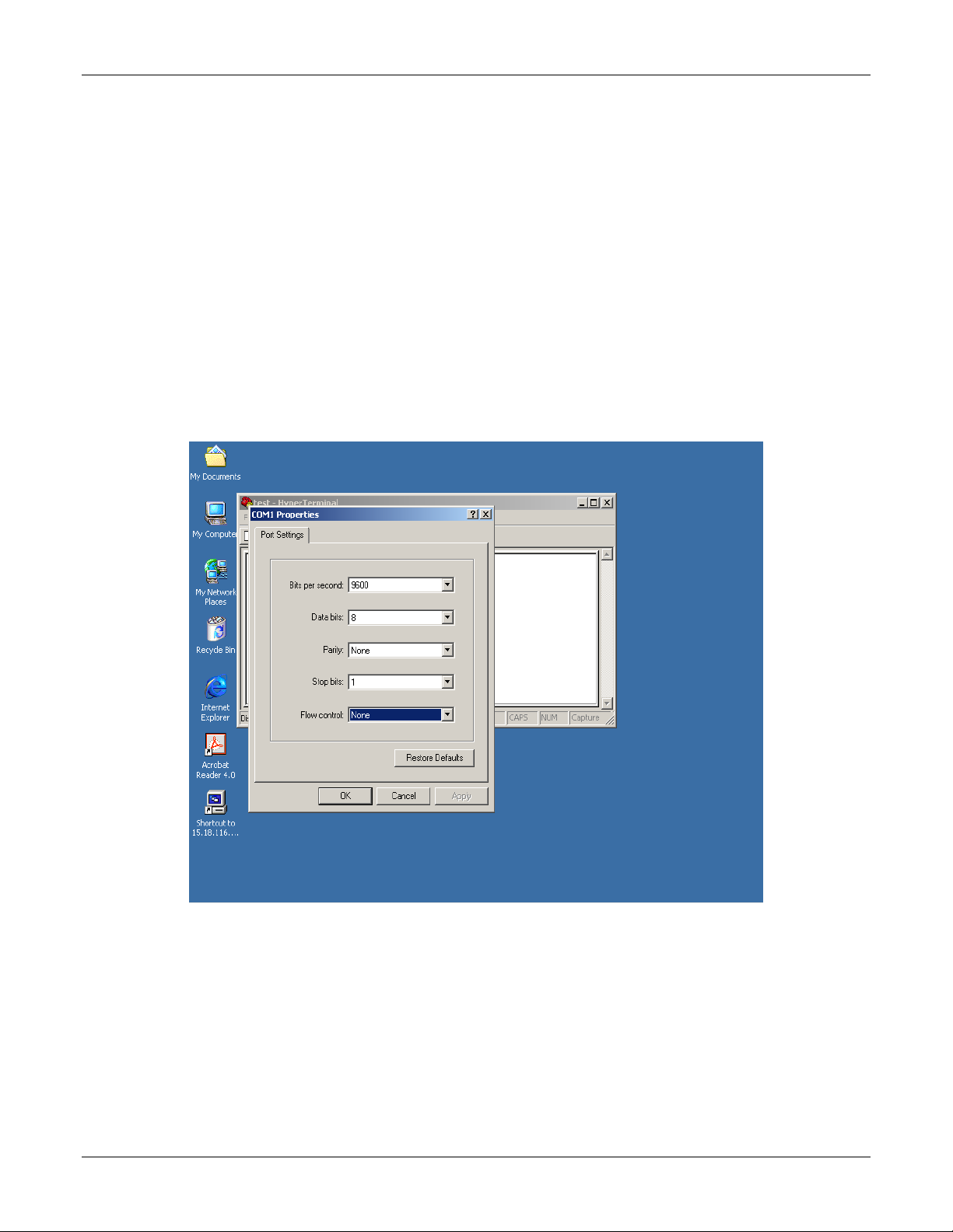
1. Connect a null modem cable to one of the controllers in the VA. As shown below, the settings are as follows:
o Bits per second: 9600
o Data bits: 8
o Parity: None
o Stop bits: 1
o Flow control: None
Then, click OK.
VA 7100/7400 Cluster Installation Guide
10/12/01 6
Page 10
VA 7100/7400 Cluster Installation Guide
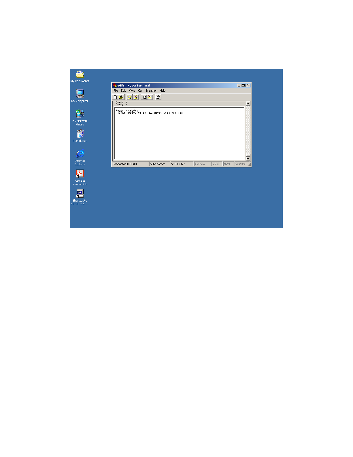
2. Referring to the window shown below, type vfpfmt at the Ready prompt, then strike the Enter key on the
keyboard. At the following (yes/no): prompt, type yes, then strike the Enter key on the keyboard.
10/12/01 7
Page 11
VA 7100/7400 Cluster Installation Guide
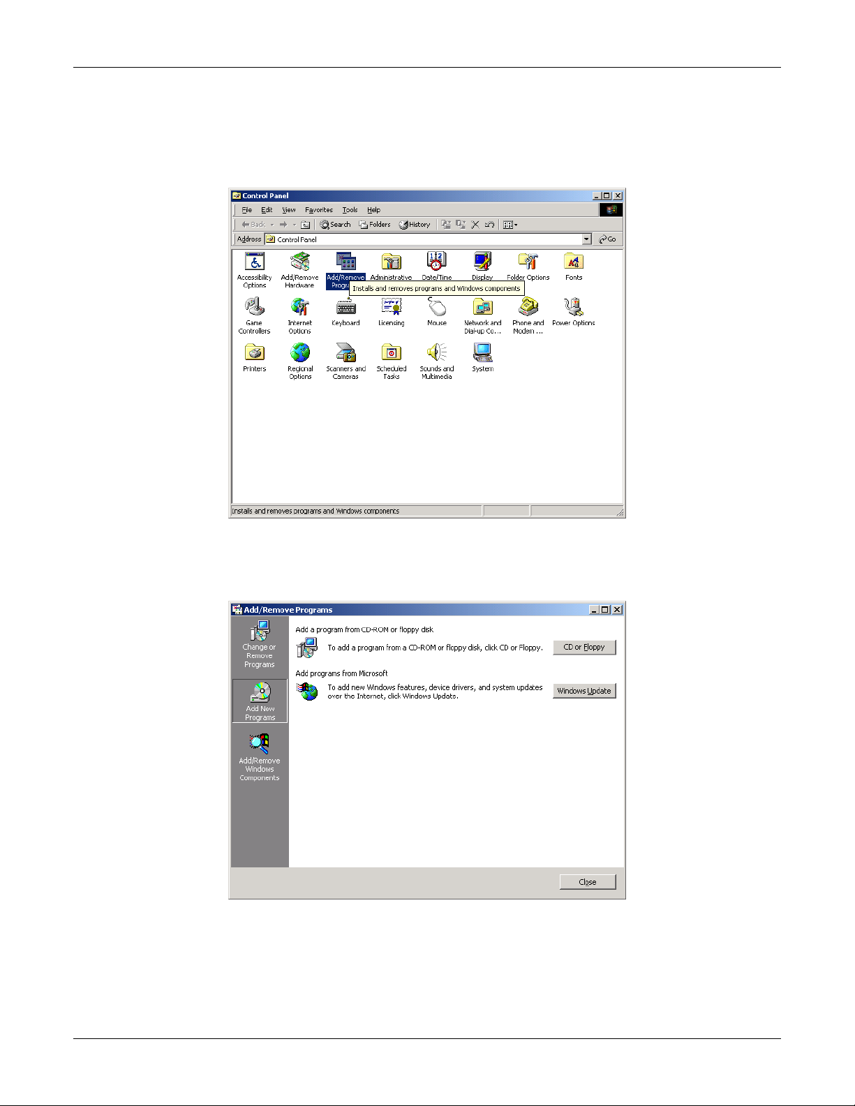
3. Insert the CD containing the HP Surestore Command View SDM software in the CD-ROM drive. On the
Windows 2000 desktop, click the desktop Start -> Settings -> Control Panel to obtain the Control Panel
window, as shown below. In the Control Panel window shown below, click Add/Remove Programs.
4. On the Add/Remove Programs window shown below, select the Add New Programs icon, then choose the
CD or Floppy option.
10/12/01 8
Page 12
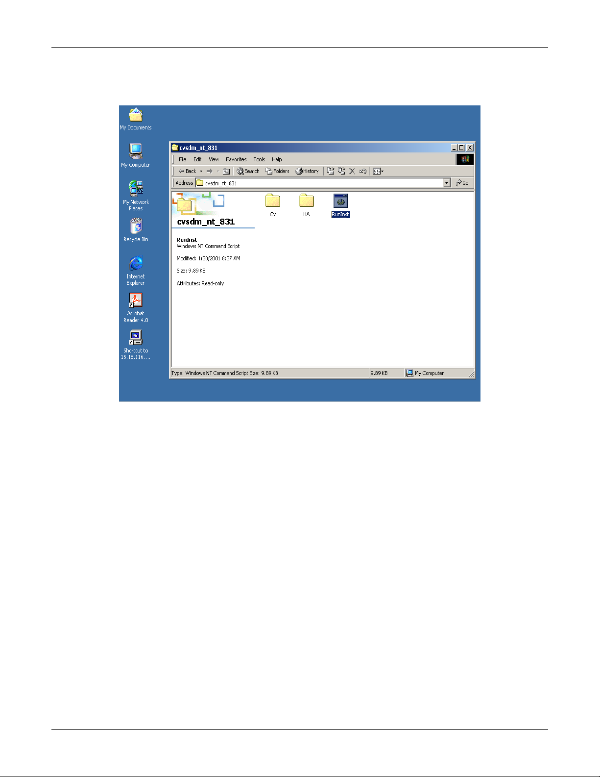
5. On the Command View CD window shown below, click RunInst.
VA 7100/7400 Cluster Installation Guide
10/12/01 9
Page 13
VA 7100/7400 Cluster Installation Guide
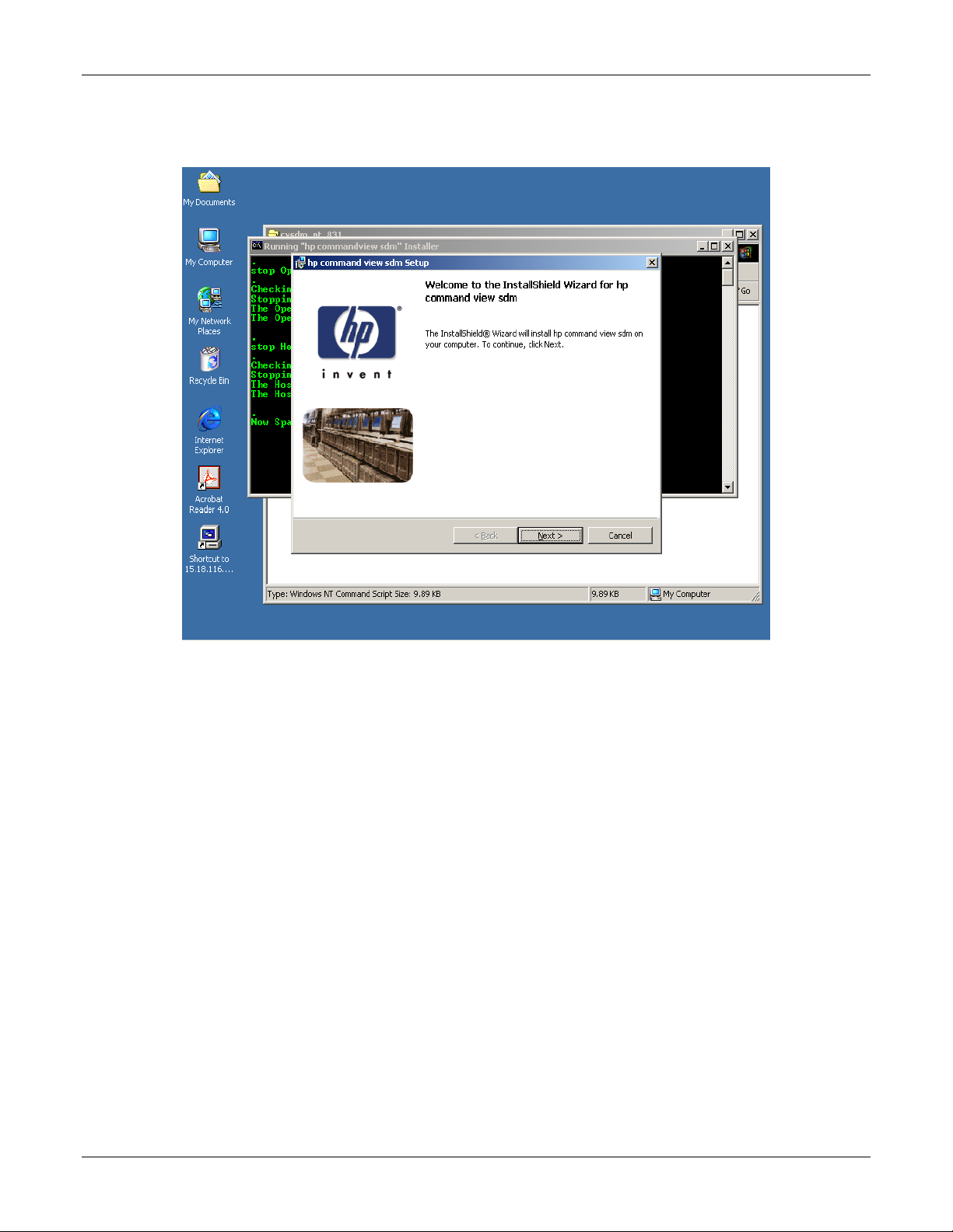
6. On the InstallShield Wizard for hp command view sdm window shown below, click Next.
10/12/01 10
Page 14
VA 7100/7400 Cluster Installation Guide
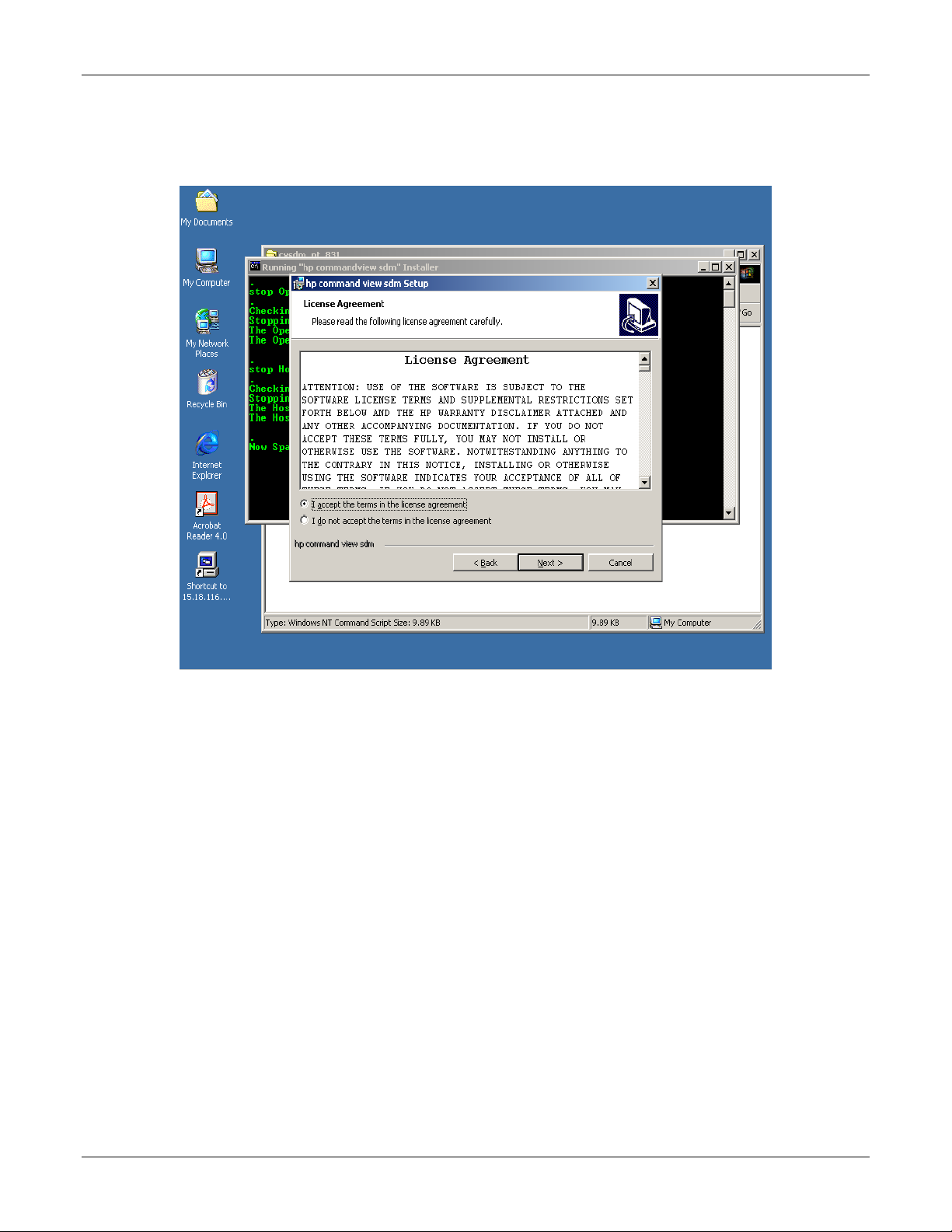
7. On the License Agreement window shown below, click the I accept the terms in the license agreement
button, then click Next.
10/12/01 11
Page 15
VA 7100/7400 Cluster Installation Guide
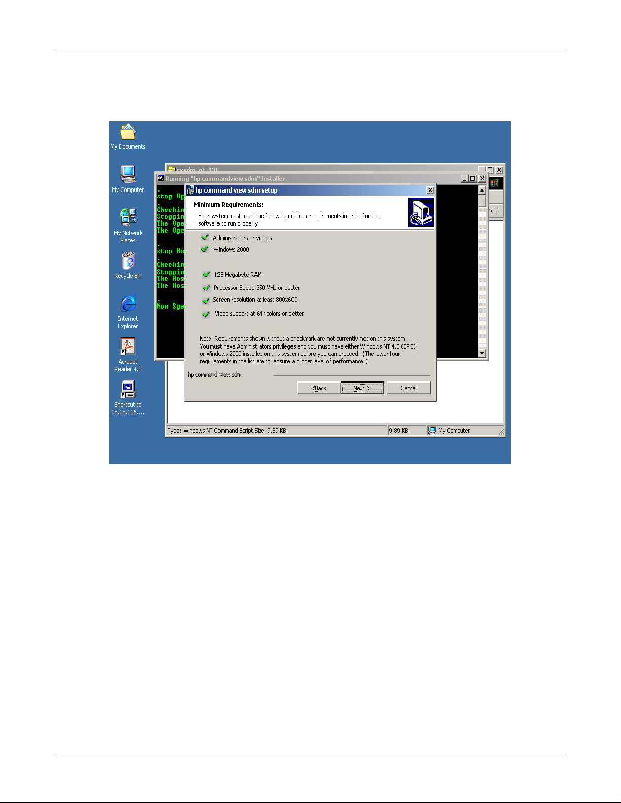
8. On the Minimum Requirements window shown below, verify that the six settings are checked as shown. Then,
click Next.
10/12/01 12
Page 16
VA 7100/7400 Cluster Installation Guide
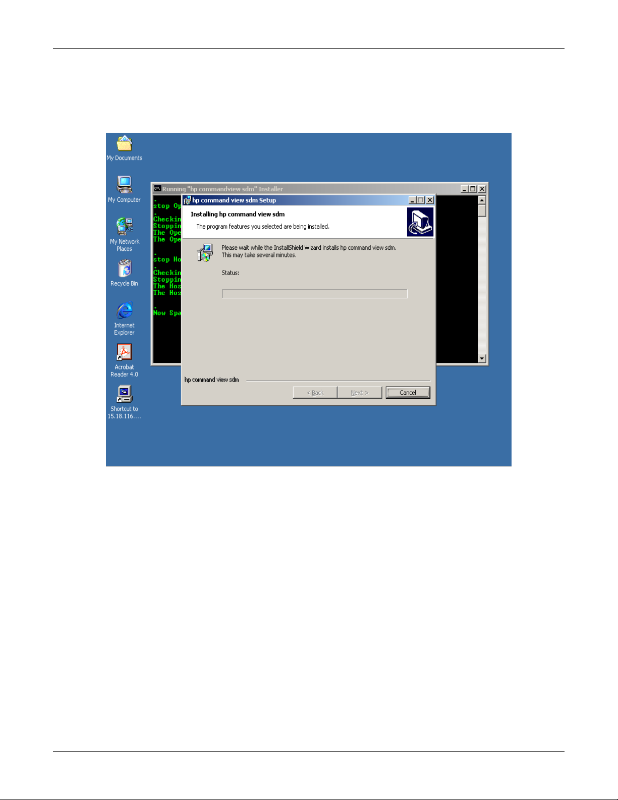
9. The Installing hp command view sdm window as shown below appears and begins the software installation. It
may require several minutes to complete the installation, however. Observe the Status bar in the displayed
window. When the software installation is complete, click Next.
10/12/01 13
Page 17

VA 7100/7400 Cluster Installation Guide
10. On the InstallShield Wizard Completed window shown below, click Finish.
10/12/01 14
Page 18

VA 7100/7400 Cluster Installation Guide
11. The Starting HostAgent window shown below appears, and remains for a few minutes.
12. The Command Prompt window appears as shown below. The term armdiscover appears at the first C-prompt
of the window display, followed by a set of device (First VA) characteristics, as shown.
10/12/01 15
Page 19

13. On the desktop display shown below, click the hp command view sdm icon.
VA 7100/7400 Cluster Installation Guide
14. The hp command view sdm launcher window appears, as shown below. This window shows the devices (and
their characteristics) that the Command View SDM software has found. Click the FirstVA icon on the display.
10/12/01 16
Page 20

VA 7100/7400 Cluster Installation Guide
15. The hp command view sdm window appears. If necessary, click the Identity tab to obtain the VA identity
display as shown below. Then, click the LUN Management tab.
10/12/01 17
Page 21

VA 7100/7400 Cluster Installation Guide
16. The display of the hp command view sdm window under the LUN Management tab appears. Use the display
as shown below to create the following LUNs, as required:
a. Create a LUN 0 to be a 10-MB partition (this LUN will not be managed by the cluster).
NOTE The VA needs LUN 0 so that Microsoft Cluster can see LUNs over number 7.
b. Create the desired (user-definable) quorum LUNs.
c. Create the desired (user-definable) data LUNs.
10/12/01 18
Page 22

AutoPath Setup
To set up AutoPath for Windows 2000, proceed as follows:
1. Ensure that AutoPath for Windows 2000 software has been installed. Refer to the Hardware Connections and
Applicable Documents/Reference Material paragraphs of chapter 2.
2. On the desktop display, click the Start HP Auto Path Server/Client icon. The HP AutoPath - Adapters
window appears, as shown below. Verify that the Fibre Channel host adapters are listed under Adapter # and
Adapter Name. Then, click Devices.
VA 7100/7400 Cluster Installation Guide
3. The HP AutoPath - Devices window appears, as shown below. Verify that those VA LUNs that have been
configured are listed under Device # and Device Name. Then, click on one of the devices listed.
10/12/01 19
Page 23

VA 7100/7400 Cluster Installation Guide
4. Click on Device Settings and observe that the Device Settings window for the selected LUN is displayed as
shown below. On the display below, use the pull-down menu to select the desired Load Balancing Policy.
5. Repeat steps 3 and 4 for each LUN that has been configured.
6. AutoPath configuration is now complete.
Secure Manager Setup
To set up Secure Manager for Windows 2000, proceed as follows:
1. Ensure that Secure Manager for Windows 2000 software has been installed. Refer to the Hardware Connections
and Applicable Documents/Reference Material paragraphs of chapter 2.
NOTE Secure Manager is not required if this cluster is the only host communicating with the virtual array.
If there are other hosts or clusters in the system, Secure Manager is required.
2. To enable Secure Manager, proceed as follows:
a. Open a DOS window, and type the following:
armfeature -a -f LUN_SECURITY_xxGB –k <LicenseKey> <SerialNUMBER>
b. To ensure that the Secure Manager feature has been installed, type the following:
Armfeature –r <serialnumber>
10/12/01 20
Page 24

VA 7100/7400 Cluster Installation Guide
Create Permission File
An ASCII permission file for the disk array to read must be created. Permission file structure and definitions are
detailed in the following steps:
1. The listing below is an example of a Permission file.
NODEWWN 50060b00000203cb 1 CW
NODEWWN 50060b00000203cb 0 CW
NODEWWN 50060b00000202f1 1 CW
NODEWWN 50060b00000202f1 0 CW
NODEWWN 50060b000002076d 0 0
NODEWWN 50060b000002076d 1 0
NODEWWN 50060b000002120b 0 0
NODEWWN 50060b000002120b 1 0
2. In the listing of step 1 above, the indicator NODEWWN specifies the host adapter. The 16-character number that
follows is the World Wide node address
3. The first number after the node address (0 or 1, in this case) identifies the specific LUN to which permissions are
being granted.
4. The final character set of each entry is the indicator for type(s) of permissions. Types of permissions are:
o C Configure
o W Write
o R Read
o 0 None
5. As shown in the listing of step 1, permissions (CW) have been granted to LUNs 0 and 1 of four host adapter
nodes, and no permissions (0) have been granted the other four host adapter nodes. The cluster host bus adapters
get full access to LUNs 0 and 1, and the other host bus adapters get none.
Load Permission File
To load the permission file, proceed as follows:
1. Open a DOS window, and type the following:
armsecure –w –c –f c:\temp\mysecure –p <password> <serialnumber>
where
–w is for write
–c is for clear
–f is for the file
–p is for the password
2. The disk array responds with a message indicating that the array has updated the security.
3. Type the following:
armsecure –e –p <password> <serialnumber>
4. Secure Manager is now enabled.
10/12/01 21
Page 25

VA 7100/7400 Cluster Installation Guide
Identifying World-Wide Node Names
The simplest method to identify world-wide node names is to use the Brocade switches (refer to the Equipment
Required listing in chapter 2).
1. Open a browser, and enter the IP address of the Brocade switch in the disk array system.
NOTE There may be two Brocade switches in the disk array system. In that case, enter the IP address of
each Brocade switch in the system.
2. Click on the Name Server Table tab of the display as shown below, and observe the world-wide node name
(circled) for each node.
3. The Virtual Array Setup and Configuration Process is now complete. Proceed to Create the Cluster Service
Domain Account, Service Group, and OU Group Policy of chapter 4.
10/12/01 22
Page 26

VA 7100/7400 Cluster Installation Guide
4 Create the Cluster Service Domain Account, Service
Group, OU Group Policy
Introduction
This procedure of this chapter should be performed by a Network Administrator, familiar with Windows 2000 Group
Policies and Security.
General Information
The cluster service on each cluster node will run under the security context of a domain user account. This account
must be created in the customer organizational unit (OU) and named OUName clusteradmin. In addition, a new user
group called OUName Cluster Group must be created in the customer OU (ensure that the Group Scope is set to
Global and the Group Type is set to Security). This user account must have the following local rights on each cluster
node:
• Act as part of the operating system
• Back up files and directories
• Increase quotas
• Increase scheduling priority
• Load and unload device drivers
• Lock pages in memory
• Log on as a service
• Restore files and directories
These local rights will be implemented via a Group Policy created later in this chapter.
NOTE Ensure that the customer OU already exists. It should have been created when the first server for
the customer site was provisioned. Do not manually create the OU.
The domain user account (OUName clusteradmin) to be created can also be used for the SQL server service and SQL
server agent service in the SQL server cluster environment (unless the Local System account is used instead). The
new user group (OUName Cluster Group) to be created is a global security group and will initially have only one
member, the domain user account OUName clusteradmin. The global security group, however, is a container designed
to hold additional cluster user accounts. If the customer installs additional clusters into their architecture, this group
will already have the appropriate user rights set by a Cluster GPO, and no additional security changes will be required.
This group (OUName Cluster Group) must also be made a member of the Service Accounts universal security group
located in the user container for the domain.
Preliminary Operations
Ensure that all requirements detailed in chapters 2 and 3 have been thoroughly reviewed and successfully completed
before proceeding to the Account/Group Creation Procedure.
10/12/01 23
Page 27

VA 7100/7400 Cluster Installation Guide
Account/Group Creation Procedure
To create the domain user account and the new user (global security) cluster group, proceed as follows:
1. Log in to a machine that belongs to the domain where the cluster is being installed, or log in to the domain
controller itself. Go to Start, Programs, Administrative Tools, then click Active Directory Users and
Computers. Ensure that the domain that appears is the correct one; if not, right-click on Active Directory Users
and Computers, and click Connect to Domain. Enter the domain that the cluster is in, and click OK.
2. Locate the customer OU. In this procedure, the customer OU name is Genuity.
NOTE The OUName associated with the accounts and groups of this chapter should be abbreviated as
necessary to ensure that its length does not exceed the maximum numbers of characters allowed.
The OUName is user-definable, but is designated Genuity in the examples of steps 3 through 14 of
this procedure.
3. Right-click the customer OU (Genuity), and click Create New. Select User. Name the new user account
clusteradmin
(Genuity clusteradmin). Select the Password never expires option and User cannot change password options.
4. To create the cluster group, right-click the OU (Genuity), and click Create New. Select Group. Ensure that the
Group Scope Global and Group Type Security radio buttons are selected. Name the new group
Cluster Group
(Genuity Cluster Group).
5. As shown below, the clusteradmin account and the Cluster Group are highlighted in the display pane in blue.
The actual cluster group created will also have the customer OUName associated with the cluster group; in this
example, Genuity Cluster Group.
10/12/01 24
Page 28

VA 7100/7400 Cluster Installation Guide
6. After the account has been created and made a member of the cluster group, ensure that it is not a member of any
other group. Right-click the user account, go to Properties, then the Members of tab. Click Add, and add the
account to the group just created called Cluster Group (Genuity Cluster Group). As shown below, click on
Cluster Group to highlight it, and then click Set Primary Group. Membership in all other groups can now be
removed.
7. Highlight all group(s) that the account is a member of except Cluster Group (Genuity Cluster Group), and click
to remove those group names. Then, select OK. This should leave only the newly-created Cluster Group
(Genuity Cluster Group), as shown below.
10/12/01 25
Page 29

VA 7100/7400 Cluster Installation Guide
NOTE The following step places the newly-created Cluster Group (Genuity Cluster Group) into the
domain-level group called Service Accounts.
8. In the customer OU (Genuity), right-click Cluster Group (Genuity Cluster Group), and select Properties. Then,
click the Members of tab. Click Add, and select Service Accounts. Ensure that the Service Accounts group is
associated with the hosting domain folder (NTENG.NCS.BBNPLANET.com/Users), as shown below. (In the
example below, the hosting domain designation is NTENG.NCS, and the hosting domain zone is
BBNPLANET.com.) Then, click OK.
9. As shown below under the Member Of tab of the Cluster Group Properties window, observe that the
Cluster Group (Genuity Cluster Group) is a member of only the Service Accounts group. Then, click OK.
10/12/01 26
Page 30

VA 7100/7400 Cluster Installation Guide
NOTE The following steps create a GPO at the OU level to contain the security policy settings that will be
applied locally to each cluster node. This will ensure that the local computer User Rights
Assignments settings are correctly modified to assign proper permissions to the clusteradmin
(Genuity clusteradmin) account.
10. Right-click the customer OU (Genuity), then click Properties. Under the Group Policy tab of the
Genuity Properties window shown below, click New. Name the policy
Cluster Group
(Genuity Cluster Group), then click Edit to modify the GPO.
10/12/01 27
Page 31

VA 7100/7400 Cluster Installation Guide
11. When the Group Policy window shown below opens, in the left-hand pane, click Windows Settings beneath
Computer Configuration. Then, click Security Settings, Local Policies, and finally User Rights Assignment.
This is a machine policy that applies to any user who logs into the machine, although due to policy object
settings, it will only make a difference to the user in the Cluster Group (Genuity Cluster Group).
12. To edit a policy setting, right-click on the policy setting to be modified (in the right-hand pane of the Group
Policy window shown in step 11), and select Security. This opens the Security Policy Setting window, as
shown below. Click the Define these policy settings checkbox, then click the Add button. This opens another
window containing names of various cluster groups, and a Browse button. In this window, click the Browse
button, and select the newly-created (Genuity) Cluster Group. Then, click OK in the Security Policy Setting
window shown below. Note that the term Cluster Group appears in the display field, preceded by hosting
domain designation NTENG. Thus, in the window below, the display field is NTENG\Cluster Group.
10/12/01 28
Page 32

VA 7100/7400 Cluster Installation Guide
13. Perform step 12 above to edit the policy setting for each of the following user rights:
o Load and unload device drivers
o Act as part of the operating system
o Back up files and directories
o Increase quotas
o Increase scheduling priority
o Lock pages in memory
o Log on as a service
o Restore files and directories
In the right-hand pane of the Group Policy window shown in step 11, each of the above user rights must contain
the term Cluster Group, preceded by the hosting (NTENG) domain designation. In the case of Load and
unload device drivers, the following two groups must also be specified:
o Enterprise admins
o Domain admins
NOTE The Security Policy Setting window shown in step 12 is an example of what policy settings
should look like for all user rights explicitly defined, with the exception of Load and unload
device drivers.
14. When all user rights listed in step 13 have been defined, close the Group Policy window shown in step 11, and
then click OK in the Security Policy Setting window shown in step 12.
15. If logged into the domain controller, log off at this time.
10/12/01 29
Page 33

VA 7100/7400 Cluster Installation Guide
NOTE The following two steps are to be performed locally on each cluster node. Log on to each node
individually to perform these steps.
16. Open the directory C:\winnt\system32\group_policy. Set the Permissions on the gpt.ini file by right-clicking on
the file, select Properties, and then go to the Security tab. Click Add, select Service Accounts, then click OK.
Set the Permissions for the Service Accounts group to explicitly deny Read & Execute, and Read access, as
shown below. Then, click OK.
17. Finally, refresh the local machine policy on the cluster nodes by opening a command prompt and typing the
following:
C:\> secedit /refreshpolicy machine_policy /enforce
This completes creation of the Cluster Group GPO. Proceed to Chapter 5, Node 1 (Primary Node) Configuation.
10/12/01 30
Page 34

VA 7100/7400 Cluster Installation Guide
5 Node 1 (Primary Node) Configuration
Introduction
This chapter contains the step-by-step procedure for configuration of node 1, the primary node, of the VA 7100/7400
disk array in a dual-path cluster configuration.
Preliminary Operations
The following preliminary operations must be successfully completed before beginning the node 1 configuration
procedure.
1. Ensure that all requirements detailed in chapters 2 through 4 have been thoroughly reviewed and successfully
completed.
2. Ensure that configuration of the internal and external arrays has been completed.
Configuration Procedure
To configure node 1 of the cluster, proceed as follows:
1. Reboot node 1.
2. Configuration screen of the dedicated Ethernet interconnect (crossover or heartbeat) NIC for node 1 is shown
below. Enter only the IP address and Subnet mask values. For node 1 TCP/IP values, set IP address to
10.0.0.1 and Subnet mask to 255.0.0.0. Leave all other fields empty.
10/12/01 31
Page 35

VA 7100/7400 Cluster Installation Guide
3. Open the Run window as shown below by clicking the desktop Start -> Run. In the Open text box of the Run
window, enter diskmgmt.msc. Then, click OK.
4. The Write Signature and Upgrade Disk Wizard welcome window appears. Click Next.
5. The Select Disk to Write Signature window appears. Check all the disks, then click Next, as shown below.
10/12/01 32
Page 36

VA 7100/7400 Cluster Installation Guide
CAUTION It is very important not to upgrade disks because the cluster can only use basic disks, not dynamic
disks.
6. The Select Disks to Upgrade window appears. Uncheck all the disks, then click Next, as shown below.
7. The Completing the Write Signature and Upgrade Disk Wizard window appears. Click Finish.
8. The Disk Manager window appears, as shown below. Determine those disks that are basic and unpartitioned (or
unallocated). These disks are labeled Unknown and are black in color. In the Disk Manager window example
shown below, the basic, unallocated disks are Disk 3 and Disk 6.
10/12/01 33
Page 37

VA 7100/7400 Cluster Installation Guide
9. In the Disk Manager window of step 8, right-click on one of the Unknown disks (Disk 3, in this example), and
the Write Signature Disk Manager window appears as shown below.
10. Right-click in the space labeled Unallocated on Disk 3. Select Create Partition. Then, click Next when the
Create Partition Wizard window appears.
11. In the Select Partition Type window that appears as shown below, select Primary partition (the default), then
click Next.
10/12/01 34
Page 38

VA 7100/7400 Cluster Installation Guide
12. In the Specify Partition Size window that appears as shown below, enter the desired partition size in the
Amount of disk space to use: text box (1024, minimum), then click Next.
13. In the Assign Drive Letter or Path window that appears as shown below, select Assign a drive letter: (the
default) and D: from the associated pull-down menu. Then, click Next.
NOTE If D: is assigned to another drive or partition, the other drive or partition must be assigned an
alternate.
10/12/01 35
Page 39

VA 7100/7400 Cluster Installation Guide
14. In the Format Partition window that appears as shown below, select Format this partition with the following
settings: (the default). Ensure that the following settings are entered in the Formatting frame, then click Next.
o File system to use: NTFS
o Allocation unit size: Default
o Volume label: Content
o Perform a Quick Format is checked.
10/12/01 36
Page 40

VA 7100/7400 Cluster Installation Guide
15. In the Completing the Create Partition Wizard window that appears as shown below, review the entered
selections to verify accuracy. If required, click Back and make corrections as necessary. Then, click Finish to
create and format the Content partition.
NOTE The formatting time will vary with the Content partition size being created.
NOTE The following step is necessary for configuration of the dedicated Ethernet interconnect (private)
network (refer to step 2 of this procedure). Refer to Microsoft Knowledge Base article Q242430
for more information.
16. At this time, turn on node 2 power and strike the Pause key on the keyboard when the controller begins
initiating. Leave node 2 in the Pause state.
NOTE Do not perform any further node 2 operations until specifically instructed in chapter 7 because both
nodes cannot simultaneously access the external storage array before cluster service has been
installed, configured, and is up and running.
17. Continue with node 1 configuration by proceeding to Chapter 6, Cluster Setup.
10/12/01 37
Page 41

VA 7100/7400 Cluster Installation Guide
6 Cluster Setup
Introduction
This chapter provides detailed instructions for performing the cluster setup.
Preliminary Operations
The following preliminary operations must be successfully completed before beginning the Cluster Setup Procedure.
1. Ensure that all requirements detailed in chapters 2 through 5 have been thoroughly reviewed and successfully
completed.
2. Ensure that storage array is powered up and maintained in accordance with the procedure of chapter 3.
3. Ensure that node 1 is powered up and running.
4. Ensure that node 2 is powered up but in Pause mode. Refer to step 16 of the Configuration Procedure of
chapter 5.
5. Ensure that the cluster Configuration Worksheet located in Appendix A has been completely filled out.
6. On the node 1 Windows 2000 Configure Your Server window shown below, click Finish setup.
10/12/01 38
Page 42

Cluster Setup Procedure
To perform the cluster setup procedure, proceed as follows:
1. In the Add/Remove Programs window shown below, click button labeled Configure to configure cluster
service.
VA 7100/7400 Cluster Installation Guide
2. The Cluster Service Configuration Wizard Welcome window appears. Click Next.
3. In the Hardware Configuration window shown below, click I Understand to activate the Next button. Then,
click Next.
10/12/01 39
Page 43

VA 7100/7400 Cluster Installation Guide
4. In the Create or Join a Cluster window shown below, select The first node in the cluster, then click Next.
5. In the Cluster Name window shown below, type the cluster name CLUS2, then click Next.
6. In the Select an Account window shown below, enter cluster in the User name: field and the applicable
password in the Password: field for the specified domain. Then, click Next.
10/12/01 40
Page 44

VA 7100/7400 Cluster Installation Guide
7. In the Add or Remove Managed Disks window shown below, select the disk array to be used for this cluster.
Select disks in the Unmanaged disks: field, and click Add to transfer them to the Managed disks: field. After
all the desired disks have been added to the Managed disks: field, click Next.
8. In the Cluster File Storage window shown below, select disk Q: (Quorum) as the disk to store cluster files.
Then, click Next.
10/12/01 41
Page 45

9. In the Configure Cluster Network dialog box shown below, click Next.
VA 7100/7400 Cluster Installation Guide
10. In the Network Connections window for the public access NIC shown below, verify that the Network name
(Local Area Connection, in this case) is correct, check the Enable this network for cluster use box, and click
the All communications (mixed network) button. Then, click Next.
10/12/01 42
Page 46

VA 7100/7400 Cluster Installation Guide
11. In the Network Connections window for the dedicated Ethernet internal connection shown below, verify that the
Network name (private network, in this case) is correct, check the Enable this network for cluster use box,
and click the Internal cluster communications only (private network) button. Then, click Next.
12. In the Internal Cluster Communication window shown below, ensure that Private (internal cluster
communication NIC) is positioned above the Local Area Connection 2 (public access) in the Networks field. If
adjustment of the order is required, select one entry, then click Up or Down button, as required. Then, click
Next.
10/12/01 43
Page 47

VA 7100/7400 Cluster Installation Guide
13. In the Cluster IP Address window shown below, enter 15.18.116.215 in the IP address field, and repeat
verification of the public access NIC as performed in step 10. Then, click Next.
14. In the Completing the Cluster Service Configuration Wizard window shown below, click Finish to complete
the cluster node 1 configuration.
15. The message shown below appears to indicate that cluster service has started.
10/12/01 44
Page 48

VA 7100/7400 Cluster Installation Guide
16. Open the Cluster Administrator window as shown below by clicking the desktop Start -> Programs ->
Administrative Tools -> Cluster Administrator. Verify that cluster node 1 has started and is running correctly.
17. With node 1 up and running, configuration of node 2 can be performed. Proceed to chapter 7.
10/12/01 45
Page 49

VA 7100/7400 Cluster Installation Guide
7 Node 2 (Secondary/Passive Node) Configuration
Introduction
This chapter contains the step-by-step procedure for configuration of node 2, the secondary/passive node, of the
VA 7100/7400 disk array in a dual-path cluster configuration.
Preliminary Operations
The following preliminary operations must be successfully completed before beginning the cluster setup procedure.
1. Ensure that all requirements detailed in chapters 2 through 6 have been thoroughly reviewed and successfully
completed.
2. Ensure that storage array is powered up and maintained in accordance with the procedure of chapter 5.
3. Ensure that node 1 is powered up and running.
4. Remove node 2 from the Pause state, and allow node 2 to finish its booting.
Configuration Procedure
Perform the following procedure to configure node 2, the secondary or passive node.
1. Repeat the setup process of node 1 to set up node 2; that is, repeat the procedure of chapter 5. Check for
detection of any dynamic drives and change them to basic as performed in steps 4 through 7 of chapter 5. This
time, there is no need to pause any server, as was done with node 2 at the end of chapter 5. Ensure that the drive
letters are identical on both nodes (refer to step 13 of chapter 5).
2. Repeat the procedures of chapter 6 for node 2 up through step 3 of the Cluster Setup Procedure.
3. In the Create or Join a Cluster window shown below, select The second or next node in the cluster, then
click Next.
10/12/01 46
Page 50

VA 7100/7400 Cluster Installation Guide
4. In the Cluster Name window shown below, type CLUS2 in the cluster name field. Then, enter cluster in the
User name: field and the applicable password in the Password: field for the specified domain. Check the entry
in the Domain: field. All entries on the window shown below must be identical to the entries in steps 5 and 6 of
the Cluster Setup Procedure of chapter 6. Then, click Next.
5. In the Select an Account window shown below, enter the applicable password in the Password: field again.
Then, click Next.
10/12/01 47
Page 51

VA 7100/7400 Cluster Installation Guide
6. In the Completing the Cluster Service Configuration Wizard window shown below, click Finish to complete
the cluster node 2 configuration.
7. Open the Cluster Administrator window as shown below by clicking the desktop Start -> Programs ->
Administrative Tools -> Cluster Administrator. Verify that both cluster nodes 1 and 2 have started and are
running correctly. At this point, cluster setup and installation are complete and ready for installation of a cluster
resource application such as Microsoft SQL Server 2000 Enterprise Edition.
10/12/01 48
Page 52

VA 7100/7400 Cluster Installation Guide
A Configuration Worksheet
Manual Configuration Worksheet
This sheet should be filled out completely before beginning the provisioning process. Specific documents referencing
appropriate servers, DNS entries, etc. should be available for each data center. If your data center does not have one,
generate one from this base and make it available to all administrators.
Node 1 Node 2
1
Organizational Unit (OU)
2
Computer Name
3
Cluster Name
4
Cluster Account / (Password)
5
Cluster IP Address
6
Cluster Subnet Mask
7
Windows 2000 Domain Name
Items 8 - 14 Refer to the Front-End (Public) Network Adapter
8
Front-End IP Address
9
Front-End Subnet Mask
10
Front-End Default Gateway
11
Front-End Primary DNS
12
Front-End Secondary DNS
13
Front-End Duplex Mode Half Full Half Full
14
Front-End Media Type 10 100 (Mbps) 10 100 (Mbps)
Items 15 – 16 Refer to the Crossover (Private) Network Adapter
15
Private IP Address 10.0.0.1 10.0.0.2
16
Private Subnet Mask 255.0.0.0 255.0.0.0
Items 17 - 20 Refer to the Back-End Network Adapter
17
Back-End IP Address
18
Back-End Subnet Mask
19
Back-End Duplex Mode Half Full Half Full
20
Back-End Media Type 10 100 (Mbps) 10 100 (Mbps)
10/12/01 49
 Loading...