

Page 1

HP V1910 Switch Series
User Guide
59982269
Part number: 5998-2269
Software version: Release 1108
Document version: 6W100-20110615
Page 2

Legal and notice information
© Copyright 2011 Hewlett-Packard Development Company, L.P.
No part of this documentation may be reproduced or transmitted in any form or by any means without
prior written consent of Hewlett-Packard Development Company, L.P.
The information contained herein is subject to change without notice.
HEWLETT-PACKARD COMPANY MAKES NO WARRANTY OF ANY KIND WITH REGARD TO THIS
MATERIAL, INCLUDING, BUT NOT LIMITED TO, THE IMPLIED WARRANTIES OF MERCHANTABILITY
AND FITNESS FOR A PARTICULAR PURPOSE. Hewlett-Packard shall not be liable for errors contained
herein or for incidental or consequential damages in connection with the furnishing, performance, or
use of this material.
The only warranties for HP products and services are set forth in the express warranty statements
accompanying such products and services. Nothing herein should be construed as constituting an
additional warranty. HP shall not be liable for technical or editorial errors or omissions contained
herein.
Page 3

Preface
The HP V1910 Switch Series User Guide describes the software features for the HP 1910 switches and
guides you through the software configuration procedures. It also provide configuration examples to
help you apply software features to different network scenarios.
This preface includes:
Audience
Conventions
Contacting HP
Subscription service
Warranty
Documents
Audience
This documentation set is intended for:
Network planners
Field technical support and servicing engineers
Network administrators working with the HP V1910 switches
Conventions
This section describes the conventions used in this documentation.
Command conventions
Convention Description
Boldface Bold text represents commands and keywords that you enter literally as shown.
italic Italic text represents arguments that you replace with actual values.
[ ] Square brackets enclose syntax choices (keywords or arguments) that are optional.
{ x | y | ... }
Braces enclose a set of required syntax choices separated by vertical bars, from which
you select one.
[ x | y | ... ]
Square brackets enclose a set of optional syntax choices separated by vertical bars, from
which you select one or none.
{ x | y | ... } *
Asterisk marked braces enclose a set of required syntax choices separated by vertical
bars, from which you select at least one.
[ x | y | ... ] *
Asterisk marked square brackets enclose optional syntax choices separated by vertical
bars, from which you select one choice, multiple choices, or none.
&<1-n>
The argument or keyword and argument combination before the ampersand (&) sign can
be entered 1 to n times.
# A line that starts with a pound (#) sign is comments.
Page 4

GUI conventions
Convention Descri
p
tion
Boldface
Window names, button names, field names, and menu items are in Boldface. For
example, the New User window appears; click OK.
> Multi-level menus are separated by angle brackets. For example, File > Create > Folder.
Symbols
Convention Descri
p
tion
WARNING
An alert that calls attention to important information that if not understood or followed can
result in personal injury.
CAUTION
An alert that calls attention to important information that if not understood or followed can
result in data loss, data corruption, or damage to hardware or software.
IMPORTANT
An alert that calls attention to essential information.
NOTE
An alert that contains additional or supplementary information.
TIP
An alert that provides helpful information.
Network topology icons
Represents a generic network device, such as a router, switch, or firewall.
Represents a routing-capable device, such as a router or Layer 3 switch.
Represents a generic switch, such as a Layer 2 or Layer 3 switch, or a router that supports
Layer 2 forwarding and other Layer 2 features.
Port numbering in examples
The port numbers in this document are for illustration only and might be unavailable on your device.
Contacting HP
For worldwide technical support information, see the HP support website:
http://www.hp.com/support
Before contacting HP, collect the following information:
Product model names and numbers
Technical support registration number (if applicable)
Product serial numbers
Error messages
Operating system type and revision level
Detailed questions
Page 5

Subscription service
HP recommends that you register your product at the Subscriber's Choice for Business website:
http://www.hp.com/go/e-updates
After registering, you will receive e-mail notification of product enhancements, new driver versions,
firmware updates, and other product resources.
Warranty
The Hewlett-Packard Limited Warranty Statement for this product and the HP Software License Terms
which apply to any software accompanying this product are available on the HP networking Web site
at www.hp.com/networking/warranty. The customer warranty support and services information are
available on the HP networking Web site at www.hp.com/networking/support. Additionally, your
HP-authorized network reseller can provide you with assistance, both with services that they offer and
with services offered by HP.
Documents
To find related documents, browse to the Manuals page of the HP Business Support Center website:
http://www.hp.com/support/manuals
Page 6

i
Contents
Overview ······································································································································································ 1
Configuration through the web interface ··················································································································· 2
Web-based network management operating environment ·························································································· 2
Logging in to the web interface ······································································································································· 2
Default login information ········································································································································· 2
Example ····································································································································································· 3
Logging out of the web interface ····································································································································· 4
Introduction to the web interface ····································································································································· 4
Web user level ·································································································································································· 4
Introduction to the web-based NM functions ················································································································· 5
Introduction to the common items on the web pages ································································································· 12
Configuration guidelines ··············································································································································· 15
Configuration at the CLI ············································································································································· 16
Getting started with the CLI ··········································································································································· 16
Setting up the configuration environment ··········································································································· 16
Setting terminal parameters ·································································································································· 17
Logging in to the CLI ············································································································································· 20
CLI commands ································································································································································ 21
initialize ·································································································································································· 21
ipsetup ···································································································································································· 21
password ································································································································································ 22
ping ········································································································································································· 22
quit ·········································································································································································· 23
reboot ····································································································································································· 24
summary ································································································································································· 24
upgrade ·································································································································································· 25
Configuration example for upgrading the system software image at the CLI ························································· 26
Configuration wizard ················································································································································· 28
Overview ········································································································································································· 28
Basic service setup ························································································································································· 28
Entering the configuration wizard homepage ···································································································· 28
Configuring system parameters ··························································································································· 28
Configuring management IP address ·················································································································· 29
Finishing configuration wizard ···························································································································· 31
IRF stack management ··············································································································································· 32
Configuring stack management ···································································································································· 32
Stack management configuration task list ·········································································································· 32
Configuring global parameters of a stack ·········································································································· 33
Configuring stack ports ········································································································································· 35
Displaying topology summary of a stack ············································································································ 35
Displaying device summary of a stack ················································································································ 36
Logging into a member switch from the master switch ····················································································· 36
Stack configuration example ········································································································································ 36
Configuration guidelines ··············································································································································· 42
Summary ····································································································································································· 43
Displaying device summary ·········································································································································· 43
Page 7

ii
Displaying system information ····························································································································· 43
Displaying device information ····························································································································· 44
Device basic information configuration ···················································································································· 46
Configuring device basic information ·························································································································· 46
Configuring system name ····································································································································· 46
Configuring idle timeout period ··························································································································· 46
System time configuration ·········································································································································· 48
Configuring system time ················································································································································ 48
System time configuration example ····························································································································· 49
Configuration guidelines ··············································································································································· 51
Log management configuration ································································································································ 52
Configuring log management ······································································································································· 52
Configuration task list ··········································································································································· 52
Setting syslog related parameters ························································································································ 52
Displaying syslog ·················································································································································· 53
Setting loghost ······················································································································································· 55
Configuration management ······································································································································· 56
Back up configuration ···················································································································································· 56
Restore configuration ····················································································································································· 56
Save configuration ························································································································································· 57
Initialize ··········································································································································································· 58
Device maintenance ··················································································································································· 59
Software upgrade ·························································································································································· 59
Device reboot ································································································································································· 60
Electronic label ······························································································································································· 60
Diagnostic information ·················································································································································· 61
File management ························································································································································ 63
File management configuration ···································································································································· 63
Displaying file list ·················································································································································· 63
Downloading a file ··············································································································································· 64
Uploading a file····················································································································································· 64
Removing a file ······················································································································································ 64
Port management configuration ································································································································ 65
Configuring a port ························································································································································· 65
Setting operation parameters for a port ············································································································· 65
Viewing the operation parameters of a port ······································································································ 69
Port management configuration example ···················································································································· 70
Port mirroring configuration ······································································································································ 74
Introduction to port mirroring ········································································································································ 74
Implementing port mirroring ································································································································· 74
Configuring local port mirroring ·································································································································· 74
Configuration task list ··········································································································································· 74
Creating a mirroring group ·································································································································· 75
Configuring ports for a mirroring group ············································································································· 76
Configuration examples ················································································································································ 77
Local port mirroring configuration example ······································································································· 77
Configuration guidelines ··············································································································································· 80
User management ······················································································································································ 81
Overview ········································································································································································· 81
Page 8

iii
Managing users ····························································································································································· 81
Adding a local user ··············································································································································· 81
Setting the super password ·································································································································· 82
Switching to the management level ····················································································································· 83
Loopback test configuration ······································································································································ 84
Overview ········································································································································································· 84
Loopback operation ······················································································································································· 84
Configuration guidelines ··············································································································································· 85
VCT·············································································································································································· 86
Overview ········································································································································································· 86
Testing cable status ························································································································································ 86
Flow interval configuration ········································································································································ 88
Overview ········································································································································································· 88
Monitoring port traffic statistics ···································································································································· 88
Setting the traffic statistics generating interval ··································································································· 88
Viewing port traffic statistics ································································································································ 88
Storm constrain configuration ··································································································································· 90
Overview ········································································································································································· 90
Configuring storm constrain ·········································································································································· 90
Setting the traffic statistics generating interval ··································································································· 90
Configuring storm constrain ································································································································· 91
RMON configuration ················································································································································· 94
Working mechanism ············································································································································· 94
RMON groups ······················································································································································· 95
Configuring RMON ······················································································································································· 96
Configuration task list ··········································································································································· 96
Configuring a statistics entry ································································································································ 98
Configuring a history entry ··································································································································· 99
Configuring an event entry ································································································································· 100
Configuring an alarm entry ································································································································ 101
Displaying RMON statistics information ··········································································································· 103
Displaying RMON history sampling information ····························································································· 105
Displaying RMON event logs ···························································································································· 107
RMON configuration example ··································································································································· 107
Energy saving configuration ··································································································································· 112
Overview ······································································································································································· 112
Configuring energy saving on a port ························································································································ 112
SNMP configuration ··············································································································································· 114
SNMP mechanism ··············································································································································· 114
SNMP protocol version ······································································································································· 115
SNMP configuration ···················································································································································· 115
Configuration task list ········································································································································· 115
Enabling SNMP ··················································································································································· 116
Configuring an SNMP view ······························································································································· 118
Configuring an SNMP community ····················································································································· 120
Configuring an SNMP group ····························································································································· 121
Configuring an SNMP user ································································································································ 122
Configuring SNMP trap function ······················································································································· 124
SNMP configuration example ····································································································································· 125
Page 9

iv
Interface statistics ···················································································································································· 131
Overview ······································································································································································· 131
Displaying interface statistics ······································································································································ 131
VLAN configuration ················································································································································ 133
Introduction to VLAN ··········································································································································· 133
VLAN fundamentals············································································································································· 133
VLAN types ·························································································································································· 134
Introduction to port-based VLAN ······················································································································· 135
Configuring a VLAN ···················································································································································· 136
Configuration task list ········································································································································· 136
Creating VLANs ··················································································································································· 136
Selecting VLANs ·················································································································································· 137
Modifying a VLAN ·············································································································································· 138
Modifying ports ··················································································································································· 140
VLAN configuration example ······································································································································ 141
Configuration guidelines ············································································································································· 145
VLAN interface configuration ································································································································· 146
Configuring VLAN interfaces ······································································································································ 146
Configuration task list ········································································································································· 146
Creating a VLAN interface ································································································································· 146
Modifying a VLAN interface ······························································································································ 147
Voice VLAN configuration ······································································································································ 149
OUI addresses ····················································································································································· 149
Voice VLAN assignment modes ························································································································· 149
Security mode and normal mode of voice VLANs ··························································································· 150
Configuring the voice VLAN ······································································································································· 151
Configuration task list ········································································································································· 151
Configuring voice VLAN globally ······················································································································ 153
Configuring voice VLAN on a port ···················································································································· 153
Adding OUI addresses to the OUI list ·············································································································· 155
Voice VLAN configuration examples ························································································································· 155
Configuring voice VLAN on a port in automatic voice VLAN assignment mode ········································· 155
Configuring a voice VLAN on a port in manual voice VLAN assignment mode ········································· 160
Configuration guidelines ············································································································································· 166
MAC address configuration ··································································································································· 167
Configuring MAC addresses ······································································································································ 168
Configuring a MAC address entry ···················································································································· 168
Setting the aging time of MAC address entries ······························································································· 170
MAC address configuration example ························································································································ 170
MSTP configuration ················································································································································· 172
STP ················································································································································································· 172
STP protocol packets ··········································································································································· 172
Basic concepts in STP ·········································································································································· 172
How STP works ···················································································································································· 173
RSTP ··············································································································································································· 179
MSTP ·············································································································································································· 179
STP and RSTP limitations ····································································································································· 179
MSTP features ······················································································································································ 180
MSTP basic concepts ·········································································································································· 180
How MSTP works ················································································································································ 184
Implementation of MSTP on devices ·················································································································· 18 4
Page 10

v
Protocols and standards ····································································································································· 185
Configuring MSTP ························································································································································ 185
Configuration task list ········································································································································· 185
Configuring an MST region ······························································································································· 185
Configuring MSTP globally ································································································································ 187
Configuring MSTP on a port ······························································································································ 189
Displaying MSTP information of a port ············································································································· 191
MSTP configuration example ······································································································································ 194
Configuration guidelines ············································································································································· 198
Link aggregation and LACP configuration ············································································································ 200
Basic concepts ····················································································································································· 200
Link aggregation modes ····································································································································· 201
Load sharing mode of an aggregation group ·································································································· 203
Configuring link aggregation and LACP ··················································································································· 203
Configuration task list ········································································································································· 203
Creating a link aggregation group ··················································································································· 204
Displaying information of an aggregate interface ·························································································· 206
Setting LACP priority ··········································································································································· 206
Displaying information of LACP-enabled ports ································································································ 207
Link aggregation and LACP configuration example ································································································· 209
Configuration guidelines ············································································································································· 211
LLDP configuration ··················································································································································· 213
Background ·························································································································································· 213
Basic concepts ····················································································································································· 213
How LLDP works ·················································································································································· 217
Compatibility of LLDP with CDP ························································································································· 217
Protocols and standards ····································································································································· 218
Configuring LLDP ·························································································································································· 218
LLDP configuration task list ································································································································· 218
Enabling LLDP on ports ······································································································································· 219
Configuring LLDP settings on ports ···················································································································· 220
Configuring global LLDP setup ··························································································································· 224
Displaying LLDP information for a port ············································································································· 226
Displaying global LLDP information ··················································································································· 230
Displaying LLDP information received from LLDP neighbors ··········································································· 232
LLDP configuration examples ······································································································································ 232
Basic LLDP configuration example ····················································································································· 232
CDP-compatible LLDP configuration example ··································································································· 238
Configuration guidelines ············································································································································· 244
IGMP snooping configuration ································································································································ 245
Overview ······································································································································································· 245
Principle of IGMP snooping ······························································································································· 245
IGMP snooping related ports ····························································································································· 245
Work mechanism of IGMP snooping ················································································································ 246
IGMP snooping querier ······································································································································ 248
Protocols and standards ····································································································································· 248
Configuring IGMP snooping ······································································································································· 248
Configuration task list ········································································································································· 248
Enabling IGMP snooping globally ···················································································································· 249
Configuring IGMP snooping in a VLAN ··········································································································· 249
Configuring IGMP snooping port functions ······································································································ 251
Display IGMP snooping multicast entry information ························································································ 252
IGMP snooping configuration example ····················································································································· 253
Page 11

vi
Routing configuration ·············································································································································· 259
Routing table ························································································································································ 259
Static route ··························································································································································· 259
Default route ························································································································································· 260
Configuring IPv4 routing ············································································································································· 260
Displaying the IPv4 active route table ··············································································································· 260
Creating an IPv4 static route ······························································································································ 261
Static route configuration example ···························································································································· 262
Precautions ···································································································································································· 266
DHCP overview ······················································································································································· 267
Introduction to DHCP ··················································································································································· 267
DHCP address allocation ············································································································································ 267
Allocation mechanisms ······································································································································· 267
Dynamic IP address allocation process············································································································· 268
IP address lease extension·································································································································· 268
DHCP message format ················································································································································· 269
DHCP options ······························································································································································· 270
DHCP options overview ······································································································································ 270
Introduction to DHCP options ····························································································································· 270
Introduction to Option 82 ··································································································································· 270
Protocols and standards ·············································································································································· 271
DHCP relay agent configuration ···························································································································· 272
Introduction to DHCP relay agent ······························································································································ 272
Application environment ····································································································································· 272
Fundamentals ······················································································································································· 272
DHCP relay agent configuration task list ··················································································································· 273
Enabling DHCP and configuring advanced parameters for the DHCP relay agent ············································· 274
Creating a DHCP server group ·································································································································· 275
Enabling the DHCP relay agent on an interface ······································································································ 276
Configuring and displaying clients' IP-to-MAC bindings ························································································· 277
DHCP relay agent configuration example ················································································································· 277
DHCP snooping configuration ······························································································································· 281
DHCP snooping overview ··········································································································································· 281
Functions of DHCP snooping······························································································································ 281
Application environment of trusted ports ·········································································································· 282
DHCP snooping support for Option 82 ············································································································ 283
DHCP snooping configuration task list ······················································································································ 283
Enabling DHCP snooping ··········································································································································· 284
Configuring DHCP snooping functions on an interface ··························································································· 285
Displaying clients' IP-to-MAC bindings ······················································································································ 285
DHCP snooping configuration example ···················································································································· 286
Service management configuration ······················································································································· 291
Configuring service management ······························································································································ 292
Diagnostic tools ······················································································································································· 294
Ping ······································································································································································· 294
Trace route ··························································································································································· 294
Diagnostic tool operations ·········································································································································· 295
Ping operation ····················································································································································· 295
Trace route operation·········································································································································· 296
ARP management ···················································································································································· 298
ARP overview ································································································································································ 298
Page 12

vii
ARP function ························································································································································· 298
ARP message format ··········································································································································· 298
ARP operation ······················································································································································ 299
ARP table ······························································································································································ 299
Managing ARP entries ················································································································································· 300
Displaying ARP entries ········································································································································ 300
Creating a static ARP entry ································································································································ 301
Static ARP configuration example ····················································································································· 301
Gratuitous ARP ····························································································································································· 305
Introduction to gratuitous ARP ···························································································································· 305
Configuring gratuitous ARP ································································································································ 305
ARP attack defense configuration ·························································································································· 307
ARP detection ······························································································································································· 307
Introduction to ARP detection ····························································································································· 307
Configuring ARP detection ································································································································· 309
Creating a static binding entry ·························································································································· 311
802.1X fundamentals ············································································································································· 312
Architecture of 802.1X ················································································································································ 312
Controlled/uncontrolled port and port authorization status ···················································································· 312
802.1X-related protocols ············································································································································ 313
Packet formats ······················································································································································ 313
EAP over RADIUS ················································································································································ 315
Initiating 802.1X authentication ································································································································· 315
802.1X client as the initiator ······························································································································ 315
Access device as the initiator ····························································································································· 315
802.1X authentication procedures····························································································································· 316
A comparison of EAP relay and EAP termination ···························································································· 316
EAP relay ······························································································································································ 317
EAP termination ··················································································································································· 319
802.1X configuration ············································································································································· 320
HP implementation of 802.1X ···································································································································· 320
Access control methods ······································································································································ 320
Using 802.1X authentication with other features ···························································································· 320
Configuring 802.1X ···················································································································································· 321
Configuration prerequisites ································································································································ 321
802.1X configuration task list ···························································································································· 322
Configuring 802.1X globally ····························································································································· 322
Configuring 802.1X on a port ··························································································································· 324
Configuration examples ·············································································································································· 326
802.1X configuration example ·························································································································· 326
ACL assignment configuration example············································································································ 333
AAA configuration ·················································································································································· 342
Overview ······································································································································································· 342
Introduction to AAA ············································································································································ 342
Domain-based user management ······················································································································ 343
Configuring AAA ························································································································································· 343
Configuration prerequisites ································································································································ 343
Configuration task list ········································································································································· 343
Configuring an ISP domain ································································································································ 344
Configuring authentication methods for the ISP domain ················································································· 345
Configuring authorization methods for the ISP domain ·················································································· 346
Configuring accounting methods for the ISP domain ······················································································ 347
Page 13

viii
AAA configuration example ······································································································································· 349
RADIUS configuration ············································································································································· 354
Introduction to RADIUS ······································································································································· 354
Client/server model ············································································································································ 354
Security and authentication mechanisms ·········································································································· 354
Basic message exchange process of RADIUS ·································································································· 355
RADIUS packet format ········································································································································ 356
Extended RADIUS attributes ······························································································································· 358
Protocols and standards ····································································································································· 359
Configuring RADIUS ···················································································································································· 359
Configuration task list ········································································································································· 359
Configuring RADIUS servers ······························································································································ 360
Configuring RADIUS parameters ······················································································································· 361
RADIUS configuration example ·································································································································· 363
Configuration guidelines ············································································································································· 369
Users ········································································································································································ 370
Configuring users ························································································································································· 370
Configuring a local user ····································································································································· 370
Configuring a user group ··································································································································· 372
PKI configuration ····················································································································································· 374
PKI overview ································································································································································· 374
PKI terms ······························································································································································· 374
Architecture of PKI ··············································································································································· 374
Applications of PKI ·············································································································································· 375
Operation of PKI ·················································································································································· 376
Configuring PKI ···························································································································································· 376
Configuration task list ········································································································································· 376
Creating a PKI entity ··········································································································································· 379
Creating a PKI domain ······································································································································· 380
Generating an RSA key pair ······························································································································ 383
Destroying the RSA key pair ······························································································································ 383
Retrieving a certificate ········································································································································ 384
Requesting a local certificate ····························································································································· 385
Retrieving and displaying a CRL ························································································································ 386
PKI configuration example ·········································································································································· 388
Configuring a PKI entity to request a certificate from a CA ··········································································· 388
Configuration guidelines ············································································································································· 393
Port isolation group configuration ·························································································································· 394
Overview ······································································································································································· 394
Configuring a port isolation group ···························································································································· 394
Port isolation group configuration example ·············································································································· 395
Authorized IP configuration ···································································································································· 397
Overview ······································································································································································· 397
Configuring authorized IP ··········································································································································· 397
Authorized IP configuration example ························································································································· 398
Authorized IP configuration example ················································································································ 398
ACL configuration ··················································································································································· 401
ACL overview ······························································································································································· 401
Introduction to IPv4 ACL ····································································································································· 401
Effective period of an ACL ································································································································· 402
ACL step ······························································································································································· 402
Page 14

ix
Configuring an ACL ····················································································································································· 403
Configuration task list ········································································································································· 403
Configuring a time range ··································································································································· 403
Creating an IPv4 ACL ········································································································································· 405
Configuring a rule for a basic IPv4 ACL ··········································································································· 40 5
Configuring a rule for an advanced IPv4 ACL ································································································· 407
Configuring a rule for an Ethernet frame header ACL ···················································································· 410
Configuration guidelines ············································································································································· 412
QoS configuration ··················································································································································· 413
Introduction to QoS ······················································································································································ 413
Networks without QoS guarantee ····················································································································· 413
QoS requirements of new applications ············································································································· 413
Congestion: causes, impacts, and countermeasures ······················································································· 413
End-to-end QoS ···················································································································································· 415
Traffic classification ············································································································································· 415
Packet precedences ············································································································································· 416
Queue scheduling ··············································································································································· 418
Line rate ································································································································································ 420
Priority mapping ·················································································································································· 421
Introduction to priority mapping tables ············································································································· 422
QoS configuration························································································································································ 423
Configuration task lists ········································································································································ 423
Creating a class ··················································································································································· 425
Configuring match criteria ································································································································· 426
Creating a traffic behavior ································································································································· 428
Configuring traffic mirroring and traffic redirecting for a traffic behavior ··················································· 429
Configuring other actions for a traffic behavior ······························································································ 430
Creating a policy················································································································································· 431
Configuring classifier-behavior associations for the policy ············································································ 431
Applying a policy to a port ································································································································ 432
Configuring queue scheduling on a port ·········································································································· 433
Configuring line rate on a port ·························································································································· 434
Configuring priority mapping tables ················································································································· 435
Configuring priority trust mode on a port ········································································································· 436
Configuration guidelines ············································································································································· 438
ACL/QoS configuration examples ························································································································ 439
ACL/QoS configuration example ······························································································································ 439
PoE configuration ···················································································································································· 448
PoE overview ································································································································································ 448
Advantages ·························································································································································· 448
Composition ························································································································································· 448
Protocol specification ·········································································································································· 449
Configuring PoE ··························································································································································· 449
Configuring PoE ports ········································································································································· 449
Configuring non-standard PD detection ············································································································ 451
Displaying information about PSE and PoE ports ···························································································· 452
PoE configuration example ········································································································································· 452
Index ········································································································································································ 455
Page 15

1
Overview
The HP V1910 Switch Series can be configured through the command line interface (CLI), web interface,
and SNMP/MIB. These configuration methods are suitable for different application scenarios.
The web interface supports all V1910 Switch Series configurations.
The CLI provides some configuration commands to facilitate your operation. To perform other
configurations not supported by the CLI, use the web interface.
Page 16

2
Configuration through the web interface
Web-based network management operating
environment
HP provides the web-based network management function to facilitate the operations and maintenance
on HP’s network devices. Through this function, the administrator can visually manage and maintain
network devices through the web-based configuration interfaces.
Figure 1 Web-based network management operating environment
Logging in to the web interface
Default login information
The device is provided with the default Web login information. You can use the default information to log
in to the web interface.
Table 1 The default web login information
Information needed at lo
g
in Default value
Username admin
Password None
IP address of the device (VLAN-interface 1)
Default IP address of the device, depending on the status
of the network where the device resides.
1. The device is not connected to the network, or no DHCP server exists in the subnet where the
device resides
If the device is not connected to the network, or no DHCP server exists in the subnet where the device
resides, you can get the default IP address of the device on the label on the device, as shown in Figure
2. The default subnet mask is 255.255.0.0.
Figure 2 Default IP address of the device
2. A DHCP server exists in the subnet where the device resides
Page 17
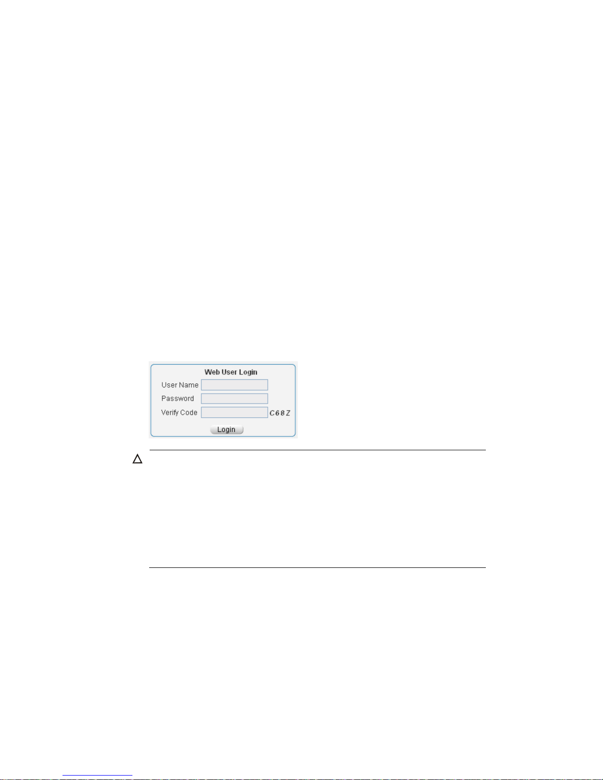
3
If a DHCP server exists in the subnet where the device resides, the device will dynamically obtain its
default IP address through the DHCP server. You can log in to the device through the console port, and
execute the summary command to view the information of its default IP address.
<Sysname> summary
Select menu option: Summary
IP Method: DHCP
IP address: 10.153.96.86
Subnet mask: 255.255.255.0
Default gateway: 0.0.0.0
<Omitted>
Example
Assuming that the default IP address of the device is 169.254.52.86, follow these steps to log in to the
device through the web interface.
Connect the device to a PC
Connect the GigabitEthernet interface of the device to a PC by using a crossover Ethernet cable (by
default, all interfaces belong to VLAN 1).
Configure an IP address for the PC and ensure that the PC and device can communicate with each
other properly.
Select an IP address for the PC from network segment 169.254.0.0/16 (except for the default IP address
of the device), for example, 169.254.52.86.
Open the browser, and input the login information.
On the PC, open the browser (IE 5.0 or later), type the IP address http://169.254.52.86 in the address
bar, and press Enter to enter the login page of the web interface, as shown in Figure 3.Input the
username admin and the verification code, leave the password blank, and click Login.
Figure 3 Login page of the web interface
CAUTION:
The PC where you configure the device is not necessarily a web-based network mana
g
ement terminal.
A web-based network management terminal is a PC used to log in to the web interface and is required
to be reachable to the device.
After logging in to the web interface, you can select Device > Users from the navigation tree, create a
new user, and select Wizard or Network > VLAN interface to configure the IP address of the VLAN
interface acting as the management interface. For more information, see the corresponding
configuration guides of these modules.
If you click the verification code displayed on the web login page, you can get a new verification code.
Up to five users can concurrently log in to the device through the web interface.
Page 18
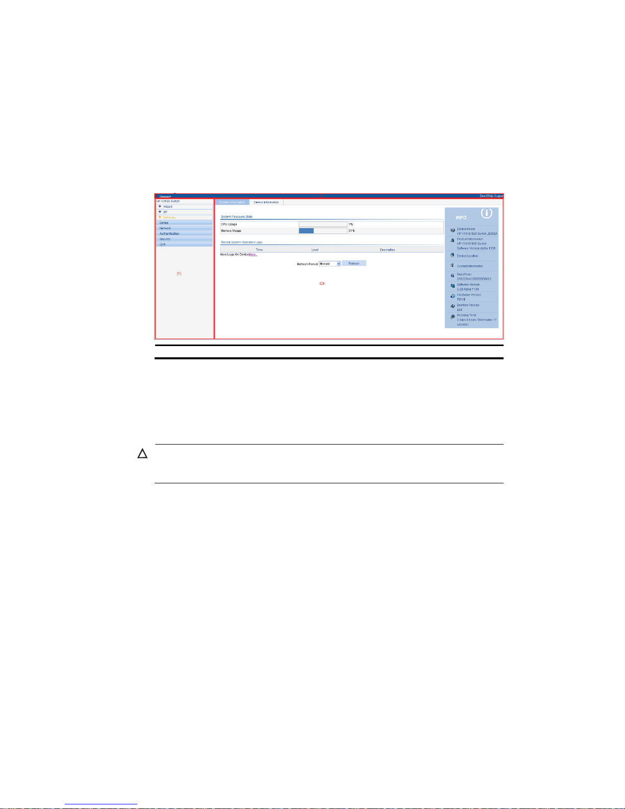
4
Logging out of the web interface
Click Logout in the upper-right corner of the web interface, as shown in Figure 4 to quit the web console.
The system does not save the current configuration automatically. Therefore, you are recommended to
save the current configuration before logout.
Introduction to the web interface
The Web interface is composed of three parts: navigation tree, title area, and body area, as shown in
Figure 4.
Figure 4 Web-based configuration interface
(1) Navigation tree (2) Body area (3) Title area
Navigation tree—Organizes the web-based NM functions as a navigation tree, where you can
select and configure functions as needed. The result is displayed in the body area.
Body area—Allows you to configure and display features.
Title area—Displays the path of the current configuration interface in the navigation tree; provides
the Help button to display the web related help information, and the Logout button to log out of the
web interface.
CAUTION:
The web network management functions not supported by the device are not displayed in the navi
g
ation
tree.
Web user level
Web user levels, from low to high, are visitor, monitor, configure, and management. A user with a
higher level has all the operating rights of a user with a lower level.
Visitor—Users of this level can only use the network diagnostic tools ping and Trace Route. They can
neither access the device data nor configure the device.
Monitor—Users of this level can only access the device data but cannot configure the device.
Page 19

5
Configure—Users of this level can access device data and configure the device, but they cannot
upgrade the host software, add/delete/modify users, or back up/restore configuration files.
Management—Users of this level can perform any operations to the device.
Introduction to the web-based NM functions
NOTE:
User level in Table 2 indicates that users of this level or users of a higher level can perform the
corresponding operations.
Table 2 Description of Web-based NM functions
Function menu Descri
p
tion
User level
Wizard IP Setup
Allows you to perform quick configuration of the
device.
Management
IRF
Setup
Displays global settings and port settings of a
stack.
Configure
Allows you to configure global parameters and
stack ports.
Management
Topology
Summary
Displays the topology summary of a stack. Configure
Device
Summary
Displays the control panels of stack members. Configure
Summary
System
Information
Displays the basic system information, system
resource state, and recent system operation logs.
Monitor
Device
Information
Displays the port information of the device. Monitor
Devi
ce
Basic
System Name
Displays and allows you to configure the system
name.
Configure
Web Idle
Timeout
Displays and allows you to configure the idle
timeout period for logged-in users.
Configure
Device
Maintenan
ce
Software
Upgrade
Allows you to configure to upload upgrade file
from local host, and upgrade the system software.
Management
Reboot Allows you to configure to reboot the device. Management
Electronic Label Displays the electronic label of the device. Monitor
Diagnostic
Information
Generates diagnostic information file, and allows
you to view or save the file to local host.
Management
System
Time
System Time
Displays and allows you to configure the system
date and time.
Configure
Syslog
Loglist
Displays and refreshes system logs. Monitor
Allows you to clear system logs. Configure
Loghost Displays and allows you to configure the loghost. Configure
Log Setup
Displays and allows you to configure the buffer
capacity, and interval for refreshing system logs.
Configure
Page 20

6
Function menu Descri
p
tion
User level
Configurati
on
Backup
Allows you to back up the configuration file to be
used at the next startup from the device to the host
of the current user.
Management
Restore
Allows you to upload the configuration file to be
used at the next startup from the host of the current
user to the device.
Management
Save
Allows you to save the current configuration to the
configuration file to be used at the next startup.
Configure
Initialize Allows you to restore the factory default settings. Configure
File
Managem
ent
File
Management
Allows you to manage files on the device, such as
displaying the file list, downloading a file,
uploading a file, and removing a file.
Management
Port
Managem
ent
Summary Displays port information by features. Monitor
Detail Displays feature information by ports. Monitor
Setup
Allows you to create, modify, delete, and
enable/disable a port, and clear port statistics.
Configure
Port
Mirroring
Summary
Displays the configuration information of a port
mirroring group.
Monitor
Create Allows you to create a port mirroring group. Configure
Remove Allows you to remove a port mirroring group. Configure
Modify Port
Allows you to configure ports for a mirroring
group.
Configure
Users
Summary
Displays the brief information of FTP and Telnet
users.
Monitor
Super Password
Allows you to configure a password for a
lower-level user to switch from the current access
level to the management level.
Management
Create Allows you to create an FTP or Telnet user. Management
Modify
Allows you to modify FTP or Telnet user
information.
Management
Remove Allows you to remove an FTP or a Telnet user. Management
Switch To
Management
Allows you to switch the current user level to the
management level.
Visitor
Loopback Loopback
Allows you to perform loopback tests on Ethernet
interfaces.
Configure
VCT VCT
Allows you to check the status of the cables
connected to Ethernet ports.
Configure
Flow
Interval
Port Traffic
Statistics
Displays the average rate at which the interface
receives and sends packets within a specified time
interval.
Monitor
Interval
Configuration
Allows you to set an interval for collecting traffic
statistics on interfaces.
Configure
Page 21

7
Function menu Descri
p
tion
User level
Storm
Constrain
Storm Constrain
Displays and allows you to set the interval for
collecting storm constrain statistics.
Displays, and allows you to create, modify, and
remove the port traffic threshold.
Configure
RMON
Statistics
Displays, and allows you to create, modify, and
clear RMON statistics.
Configure
History
Displays, and allows you to create, modify, and
clear RMON history sampling information.
Configure
Alarm
Allows you to view, create, modify, and clear
alarm entries.
Configure
Event
Allows you to view, create, modify, and clear event
entries.
Configure
Log Displays log information about RMON events. Configure
Energy
Saving
Energy Saving
Displays and allows you to configure the energy
saving settings of an interface.
Configure
SNMP
Setup
Displays and refreshes SNMP configuration and
statistics information.
Monitor
Allows you to configure SNMP. Configure
Community
Displays SNMP community information. Monitor
Allows you to create, modify and delete an SNMP
community.
Configure
Group
Displays SNMP group information. Monitor
Allows you to create, modify and delete an SNMP
group.
Configure
User
Displays SNMP user information. Monitor
Allows you to create, modify and delete an SNMP
user.
Configure
Trap
Displays the status of the SNMP trap function and
information about target hosts.
Monitor
Allows you to enable or disable the SNMP trap
function, or create, modify and delete a target host.
Configure
View
Displays SNMP view information. Monitor
Allows you to create, modify and delete an SNMP
view.
Configure
Interface
Statistics
Interface
Statistics
Displays and allows you to clear the statistics
information of an interface.
Configure
Net
VLAN Select VLAN Allows you to select a VLAN range. Monitor
Page 22

8
Function menu Descri
p
tion
User level
Create Allows you to create VLANs. Configure
Port Detail Displays the VLAN-related details of a port. Monitor
Detail Displays the member port information of a VLAN. Monitor
Modify VLAN
Allows you to modify the description and member
ports of a VLAN.
Configure
Modify Port
Allows you to change the VLAN to which a port
belongs.
Configure
Remove Allows you to remove VLANs. Configure
VLAN
Interface
Summary
Displays information about VLAN interfaces by
address type.
Monitor
Create
Allows you to create VLAN interfaces and
configure IP addresses for them.
Configure
Modify
Allows you to modify the IP addresses and status of
VLAN interfaces.
Configure
Remove Allows you to remove VLAN interfaces. Configure
Voice
VLAN
Summary
Displays voice VLAN information globally or on a
port.
Monitor
Setup Allows you to configure the global voice VLAN. Configure
Port Setup Allows you to configure a voice VLAN on a port. Configure
OUI Summary
Displays the addresses of the OUIs that can be
identified by voice VLAN.
Monitor
OUI Add
Allows you to add the address of an OUI that can
be identified by voice VLAN.
Configure
OUI Remove
Allows you to remove the address of an OUI that
can be identified by voice VLAN.
Configure
MAC
MAC
Displays MAC address information. Monitor
Allows you to create and remove MAC addresses. Configure
Setup
Displays and allows you to configure MAC address
aging time.
Configure
MSTP
Region
Displays information about MST regions. Monitor
Allows you to modify MST regions. Configure
Global Allows you to set global MSTP parameters. Configure
Port Summary Displays the MSTP information of ports. Monitor
Port Setup Allows you to set MSTP parameters on ports. Configure
Link
Aggregati
on
Summary
Displays information about link aggregation
groups.
Monitor
Create Allows you to create link aggregation groups. Configure
Modify Allows you to modify link aggregation groups. Configure
Remove Allows you to remove link aggregation groups. Configure
Page 23

9
Function menu Descri
p
tion
User level
LACP
Summary
Displays information about LACP-enabled ports
and their partner ports.
Monitor
Setup Allows you to set LACP priorities. Configure
LLDP
Port Setup
Displays the LLDP configuration information, local
information, neighbor information, statistics
information, and status information of a port.
Monitor
Allows you to modify LLDP configuration on a port. Configure
Global Setup
Displays global LLDP configuration information. Monitor
Allows you to configure global LLDP parameters. Configure
Global
Summary
Displays global LLDP local information and
statistics.
Monitor
Neighbor
Summary
Displays global LLDP neighbor information. Monitor
IGMP
Snooping
Basic
Displays global IGMP snooping configuration
information or the IGMP snooping configuration
information in a VLAN, and allows you to view the
IGMP snooping multicast entry information.
Monitor
Allows you to configure IGMP snooping globally or
in a VLAN.
Configure
Advanced
Displays the IGMP snooping configuration
information on a port.
Monitor
Allows you to configure IGMP snooping on a port. Configure
IPv4
Routing
Summary Displays the IPv4 active route table. Monitor
Create Allows you to create an IPv4 static route. Configure
Remove Allows you to delete the selected IPv4 static routes. Configure
DHCP
DHCP Relay
Displays information about the DHCP status,
advanced configuration information of the DHCP
relay agent, DHCP server group configuration,
DHCP relay agent interface configuration, and the
DHCP client information.
Monitor
Allows you to enable/disable DHCP, configure
advanced DHCP relay agent settings, configure a
DHCP server group, and enable/disable the DHCP
relay agent on an interface.
Configure
DHCP
Snooping
Displays the status, trusted and untrusted ports and
DHCP client information of DHCP snooping.
Monitor
Allows you to enable/disable DHCP snooping,
and configure DHCP snooping trusted and
untrusted ports.
Configure
Service Service
Displays the states of services: enabled or
disabled.
Configure
Allows you to enable/disable services, and set
related parameters.
Management
Page 24

10
Function menu Descri
p
tion
User level
Diagnostic
Tools
Ping Allows you to ping an IPv4 address. Visitor
Trace Route Allows you to perform trace route operations. Visitor
ARP
Managem
ent
ARP Table
Displays ARP table information. Monitor
Allows you to add, modify, and remove ARP
entries.
Configure
Gratuitous ARP
Displays the configuration information of gratuitous
ARP.
Monitor
Allows you to configure gratuitous ARP. Configure
ARP
Anti-Attack
ARP Detection
Displays ARP detection configuration information. Monitor
Allows you to configure ARP detection. Configure
Auth
entic
ation
802.1X 802.1X
Displays 802.1X configuration information
globally or on a port.
Monitor
Allows you to configure 802.1X globally or on a
port.
Configure
AAA
Domain Setup
Displays ISP domain configuration information. Monitor
Allows you to add and remove ISP domains. Management
Authentication
Displays the authentication configuration
information of an ISP domain.
Monitor
Allows you to specify authentication methods for an
ISP domain.
Management
Authorization
Displays the authorization method configuration
information of an ISP domain.
Monitor
Allows you to specify authorization methods for an
ISP domain.
Management
Accounting
Displays the accounting method configuration
information of an ISP domain.
Monitor
Allows you to specify accounting methods for an
ISP domain.
Management
RADIUS
RADIUS Server
Displays and allows you to configure RADIUS
server information.
Management
RADIUS Setup
Displays and allows you to configure RADIUS
parameters.
Management
Users
Local User
Displays configuration information about local
users.
Monitor
Allows you to create, modify and remove a local
user.
Management
User Group
Displays configuration information about user
groups.
Monitor
Allows you to create, modify and remove a user
group.
Management
PKI Entity Displays information about PKI entities. Monitor
Page 25

11
Function menu Descri
p
tion
User level
Allows you to add, modify, and delete a PKI entity. Configure
Domain
Displays information about PKI domains. Monitor
Allows you to add, modify, and delete a PKI
domain.
Configure
Certificate
Displays the certificate information of PKI domains
and allows you to view the contents of a certificate.
Monitor
Allows you to generate a key pair, destroy a key
pair, retrieve a certificate, request a certificate, and
delete a certificate.
Configure
CRL
Displays the contents of the CRL. Monitor
Allows you to receive the CRL of a domain. Configure
Secu
rity
Port Isolate
Group
Summary Displays port isolation group information. Monitor
Modify Allows you to configure a port isolation group. Configure
Authorized
IP
Summary
Displays the configurations of authorized IP, the
associated IPv4 ACL list, and the associated IPv6
ACL list.
Management
Setup Allows you to configure authorized IP. Management
QoS
Time
Range
Summary Displays time range configuration information. Monitor
Create Allows you to create a time range. Configure
Remove Allows you to delete a time range. Configure
ACL IPv4
Summary Displays IPv4 ACL configuration information. Monitor
Create Allows you to create an IPv4 ACL. Configure
Basic Setup Allows you to configure a rule for a basic IPv4 ACL. Configure
Advanced
Setup
Allows you to configure a rule for an advanced
IPv4 ACL.
Configure
Link Setup Allows you to create a rule for a link layer ACL. Configure
Remove Allows you to delete an IPv4 ACL or its rules. Configure
Queue
Summary Displays the queue information of a port. Monitor
Setup Allows you to configure a queue on a port. Configure
Line Rate
Summary Displays line rate configuration information. Monitor
Setup Allows you to configure the line rate. Configure
Classifier
Summary Displays classifier configuration information. Monitor
Create Allows you to create a class. Configure
Setup
Allows you to configure the classification rules for a
class.
Configure
Remove
Allows you to delete a class or its classification
rules.
Configure
Behavior
Summary Displays traffic behavior configuration information. Monitor
Create Allows you to create a traffic behavior. Configure
Page 26

12
Function menu Descri
p
tion
User level
Setup
Allows you to configure actions for a traffic
behavior.
Configure
Port Setup
Allows you to configure traffic mirroring and traffic
redirecting for a traffic behavior
Configure
Remove Allows you to delete a traffic behavior. Configure
QoS Policy
Summary Displays QoS policy configuration information. Monitor
Create Allows you to create a QoS policy. Configure
Setup
Allows you to configure the classifier-behavior
associations for a QoS policy.
Configure
Remove
Allows you to delete a QoS policy or its
classifier-behavior associations.
Configure
Port Policy
Summary Displays the QoS policy applied to a port. Monitor
Setup Allows you to apply a QoS policy to a port. Configure
Remove Allows you to remove the QoS policy from the port. Configure
Priority
Mapping
Priority
Mapping
Displays priority mapping table information. Monitor
Allows you to modify the priority mapping entries. Configure
Port Priority Port Priority
Displays port priority and trust mode information. Monitor
Allows you to modify port priority and trust mode. Configure
PoE PoE
Summary
Displays PSE information and PoE interface
information.
Monitor
Setup Allows you to configure a PoE interface. Configure
Introduction to the common items on the web pages
Buttons and icons
Table 3 Commonly used buttons and icons
Button and icon Function
Used to apply the configuration on the current page.
Used to cancel the configuration on the current page, and return to the
corresponding list page or the Device Info page.
Used to refresh the information on the current page.
Used to clear all the information on a list or all statistics.
Used to enter a page for adding an item.
,
Used to remove the selected items.
Used to select all the entries on a list, or all the ports on the device panel.
Page 27
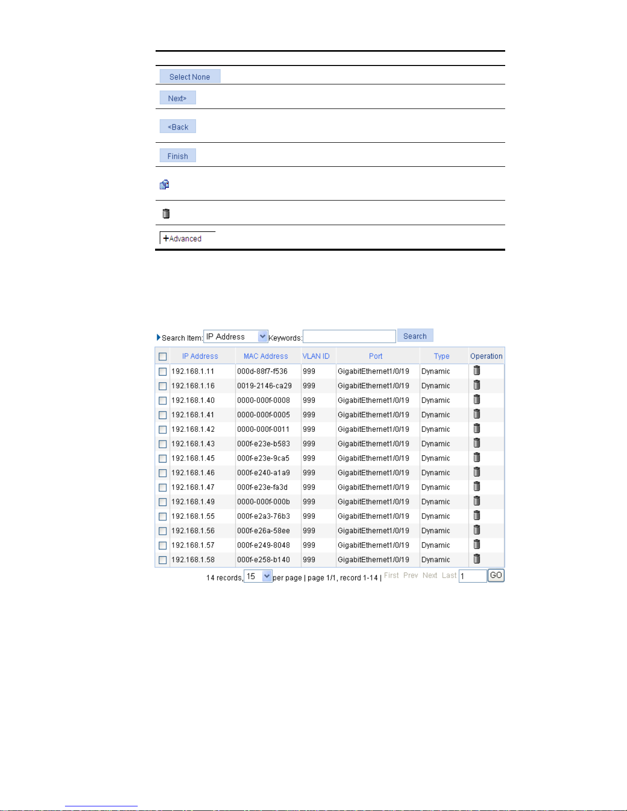
13
Button and icon Function
Used to deselect all the entries on a list, or all the ports on the device panel.
Generally present on the configuration wizard; used to buffer but not apply
the configuration of the current step and enter the next configuration step.
Generally present on the configuration wizard; used to buffer but not apply
the configuration of the current step and return to the previous configuration
step.
Generally present on the configuration wizard; used to apply the
configurations of all configuration steps.
Generally present on the “Operation” column on a list; used to enter the
modification page of an item so that you can modify the configurations of
the item.
Generally present on the “Operation” column on a list; used to delete the
item corresponding to this icon.
Click the plus sign before a corresponding item. You can see the collapsed
contents.
Page display
The web interface can display a long list by pages, as shown in Figure 5. You can set the number of
entries displayed per page, and use the First, Prev, Next, and Last links to view the contents on the first,
previous, next, and last pages, or go to any page that you want to view.
Figure 5 Content display by pages
Page 28
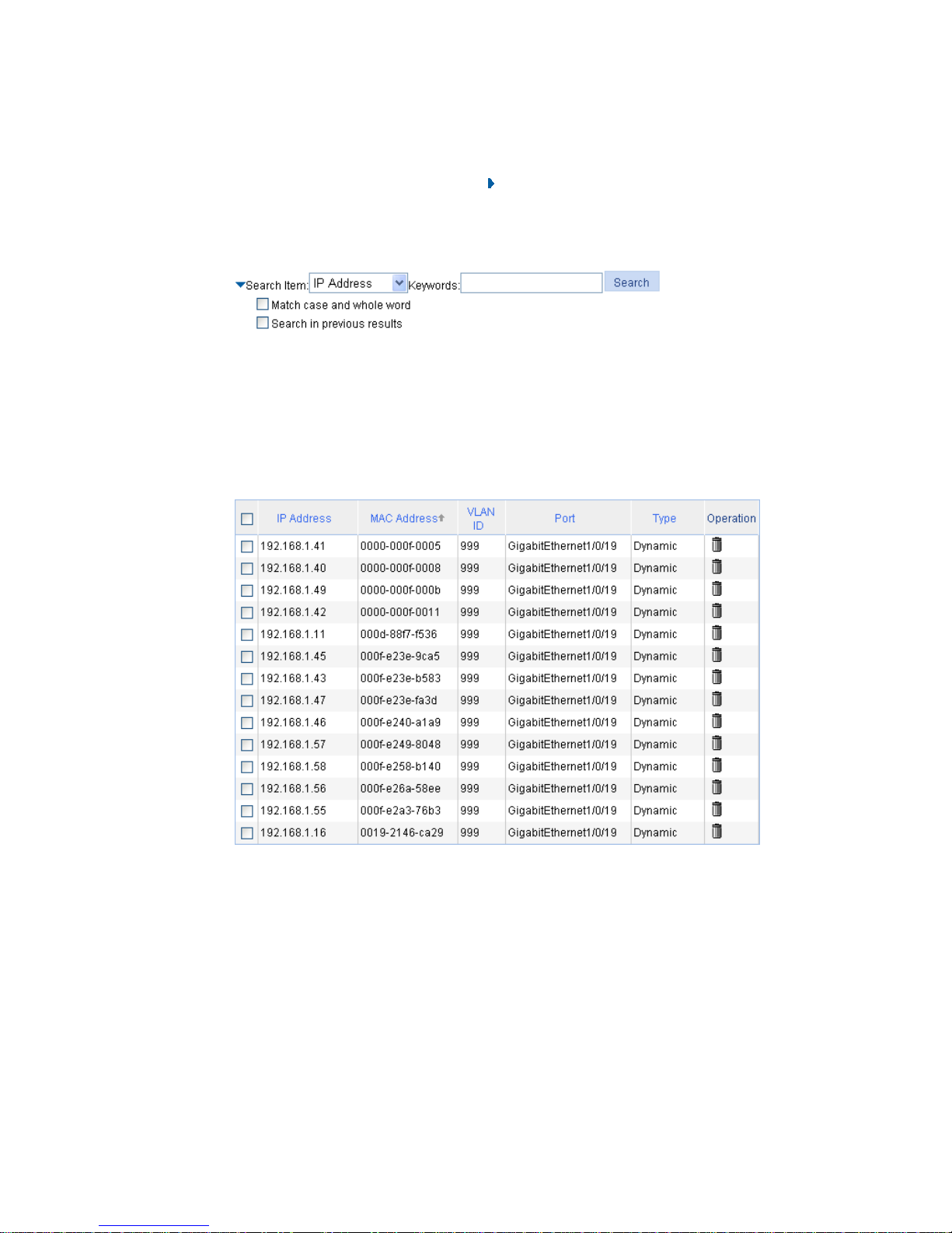
14
Search function
On some list pages, the web interface provides basic and advanced search functions. You can use the
search function to display those entries matching certain search criteria.
Basic search function—Select a search item from the drop-down list as shown in Figure 5, input the
keyword, and click the Query button to display the entries that match the criteria.
Advanced search function—You can click
before Search Item, as shown in Figure 6. You can
select Match case and whole word, that is, the item to be searched must completely match the
keyword, or you can select Search in previous results. If you do not select exact search, fuzzy search
is performed.
Figure 6 Advanced search
Sorting function
On some list pages, the web interface provides the sorting function to display the entries in a certain
order.
As shown in Figure 7, you can click the blue heading item of each column to sort the entries based on the
heading item you selected. Then, the heading item is displayed with an arrow beside it. The upward
arrow indicates the ascending order, and the downward arrow indicates the descending order.
Figure 7 Sort display (based on MAC address in the ascending order)
Page 29

15
Configuration guidelines
The web console supports Microsoft Internet Explorer 6.0 SP2 and higher.
The web console does not support the Back, Next, Refresh buttons provided by the browser. Using
these buttons may result in abnormal display of web pages.
When the device is performing spanning tree calculation, you cannot log in to or use the web
interface.
The Windows firewall limi ts th e num ber of TCP connections, so when you use I E to log in to th e we b
interface, sometimes you may be unable to open the web interface. To avoid this problem, turn off
the Windows firewall before login.
If the software version of the device changes, when you log in to the device through the web
interface, delete the temporary Internet files of IE; otherwise, the web page content may not be
displayed correctly.
Page 30
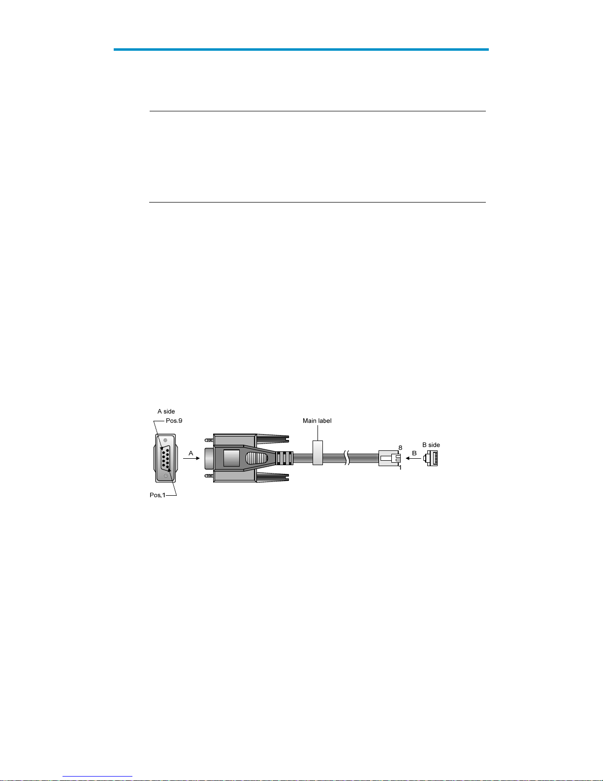
16
Configuration at the CLI
NOTE:
The HP V1910 Switch Series can be confi
g
ured through the CLI, web interface, and SNMP/MIB, amon
g
which the web interface supports all V1910 Switch Series configurations. These configuration methods
are suitable for different application scenarios. As a supplementary to the web interface, the CLI
provides some configuration commands to facilitate your operation, which are described in this chapter.
To perform other configurations not supported by the CLI, use the web interface.
You will enter user view directly after you log in to the device. Commands in the document are all
performed in user view.
Getting started with the CLI
As a supplementary to the web interface, the CLI provides some configuration commands to facilitate
your operation. For example, if you forget the IP address of VLAN-interface 1 and cannot log in to the
device through the web interface, you can connect the console port of the device to a PC, and
reconfigure the IP address of VLAN-interface 1 at the CLI.
This section describes using the CLI to manage the device.
Setting up the configuration environment
To set up the configuration environment, connect a terminal (a PC in this example) to the console port on
the switch with a console cable.
A console cable is an 8-core shielded cable, with a crimped RJ-45 connector at one end for connecting
to the console port of the switch, and a DB-9 female connector at the other end for connecting to the
serial port on the console terminal.
Figure 8 Console cable
Use a console cable to connect a terminal device to the switch, as follows:
Step1 Plug the DB-9 female connector to the serial port of the console terminal or PC.
Step2 Connect the RJ-45 connector to the console port of the switch.
Page 31

17
Figure 9 Network diagram for configuration environment setup
CAUTION:
Identify the mark on the console port to ensure that you are connecting to the correct port.
NOTE:
The serial port on a PC does not support hot swapping. When you connect a PC to a powered-on switch,
connect the DB-9 connector of the console cable to the PC before connecting the RJ-45 connector to the
switch.
When you disconnect a PC from a powered-on switch, Disconnect the DB-9 connector of the console
cable from the PC after disconnecting the RJ-45 connector from the switch.
Setting terminal parameters
To configure and manage the switch, you must run a terminal emulator program on the console terminal,
for example, a PC. This section uses Windows XP HyperTerminal as an example.
The following are the required terminal settings:
Bits per second—38400
Data bits—8
Parit y—None
Stop bits—1
Flow control—None
Emulation—VT100
Follow these steps to set terminal parameters, for example, on a Windows XP HyperTerminal:
Step1 Select Start > All Programs > Accessories > Communications > HyperTerminal, and in the Connection
Description dialog box that appears, type the name of the new connection in the Name text box and
click OK.
Page 32

18
Figure 10 Connection description of the HyperTerminal
Step2 Select the serial port to be used from the Connect using drop-down list, and click OK.
Figure 11 Set the serial port used by the HyperTerminal connection
Step3 Set Bits per second to 38400, Data bits to 8, Parity to None, Stop bits to 1, and Flow control to None,
and click OK.
Page 33

19
Figure 12 Set the serial port parameters
Step4 Select File > Properties in the HyperTerminal window.
Figure 13 HyperTerminal window
Step5 Click the Settings tab, set the emulation to VT100, and click OK in the Switch Properties dialog box.
Page 34

20
Figure 14 Set terminal emulation in Switch Properties dialog box
Logging in to the CLI
The login process requires a username and password. The default username for first time configuration
is admin, no password is required. Usernames and passwords are case sensitive.
To log in to the CLI:
Step1 Press Enter. The Username prompt displays:
Login authentication
Username:
Step2 Enter your username at the Username prompt.
Username:admin
Step3 Press Enter. The Password prompt display
Password:
The login information is verified, and displays the following CLI menu:
<HP V1910 Switch>
If the password is invalid, the following message appears and process restarts.
% Login failed!
Page 35

21
CLI commands
This Command section contains the following commands:
To do… Use the command…
Display a list of CLI commands on the device ?
Reboot the device and run the default configuration initialize
Specify VLAN-interface 1 to obtain an IP address through
DHCP or manual configuration
ipsetup { dhcp | ip address ip-address { mask
| mask-length } [ default-gateway
ip-address ] }
Modify the login password of a user password
Download the Boot ROM image or system software image file
from the TFTP server and specify as the startup configuration
file
upgrade server-address source-filename
{ bootrom | runtime }
Reboot the device and run the main configuration file reboot
View the summary information of the device summary
Ping a specified destination ping host
initialize
Syntax
initialize
Parameters
None
Description
Use the initialize command to delete the configuration file to be used at the next startup and reboot the
device with the default configuration being used during reboot.
Use the command with caution because this command deletes the configuration file to be used at the
next startup and restores the factory default settings.
Examples
# Delete the configuration file to be used at the next startup and reboot the device with the default
configuration being used during reboot.
<Sysname> initialize
The startup configuration file will be deleted and the system will be rebooted.Continue?
[Y/N]:y
Please wait...
ipsetup
Syntax
ipsetup { dhcp | ip address ip-address { mask | mask-length } [ default-gateway ip-address ] }
Parameters
dhcp: Specifies the interface to obtain an IP address through DHCP.
Page 36

22
ip-address ip-address: Specifies an IP address for VLAN-interface 1 in dotted decimal notation.
mask: Subnet mask in dotted decimal notation.
mask-length: Subnet mask length, the number of consecutive ones in the mask, in the range of 0 to 32.
default-gateway ip-address: Specifies the IP address of the default gateway or the IP address of the
outbound interface. With this argument and keyword combination configured, the command not only
assigns an IP address to the interface, but also specifies a default route for the device.
Description
Use the ipsetup dhcp command to specify VLAN-interface 1 to obtain an IP address through DHCP.
Use the ipsetup ip address ip-address { mask | mask-length } command to assign an IP address to
VLAN-interface 1.
By default, the device automatically obtains its IP address through DHCP; if fails, it uses the assigned
default IP address. For more information, see Figure 2.
If there is no VLAN-interface 1, either command creates VLAN-interface 1 first, and then specifies its IP
address.
Examples
# Create VLAN-interface 1 and specify the interface to obtain an IP address through DHCP.
<Sysname> ipsetup dhcp
# Create VLAN-interface 1 and assign 192.168.1.2 to the interface, and specify 192.168.1.1 as the default
gateway.
<Sysname> ipsetup ip-address 192.168.1.2 24 default-gateway 192.168.1.1
password
Syntax
password
Parameters
None
Description
Use the password command to modify the login password of a user.
Examples
# Modify the login password of user admin.
<Sysname> password
Change password for user: admin
Old password: ***
Enter new password: **
Retype password: **
The password has been successfully changed.
ping
Syntax
ping host
Page 37

23
Parameters
host: Destination IP address (in dotted decimal notation), URL, or host name (a string of 1 to 20
characters).
Description
Use the ping command to ping a specified destination.
You c a n e nter Ctrl+C to terminate a ping operation.
Examples
# Ping IP address 1.1.2.2.
<Sysname> ping 1.1.2.2
PING 1.1.2.2: 56 data bytes, press CTRL_C to break
Reply from 1.1.2.2: bytes=56 Sequence=1 ttl=254 time=205 ms
Reply from 1.1.2.2: bytes=56 Sequence=2 ttl=254 time=1 ms
Reply from 1.1.2.2: bytes=56 Sequence=3 ttl=254 time=1 ms
Reply from 1.1.2.2: bytes=56 Sequence=4 ttl=254 time=1 ms
Reply from 1.1.2.2: bytes=56 Sequence=5 ttl=254 time=1 ms
--- 1.1.2.2 ping statistics -- 5 packet(s) transmitted
5 packet(s) received
0.00% packet loss
round-trip min/avg/max = 1/41/205 ms
The output shows that IP address 1.1.2.2 is reachable and the echo replies are all returned from the
destination. The minimum, average, and maximum roundtrip intervals are 1 millisecond, 41 milliseconds,
and 205 milliseconds respectively.
quit
Syntax
quit
Parameters
None
Description
Use the quit command to log out of the system.
Examples
# Log out of the system.
<Sysname> quit
******************************************************************************
* Copyright (c) 2004-2011 Hewlett-Packard Development Company, L.P. *
* Without the owner's prior written consent, *
* no decompiling or reverse-engineering shall be allowed. *
******************************************************************************
User interface aux0 is available.
Page 38

24
Please press ENTER.
reboot
Syntax
reboot
Parameters
None
Description
Use the reboot command to reboot the device and run the main configuration file.
Use the command with caution because reboot results in service interruption.
If the main configuration file is corrupted or does not exist, the device cannot be rebooted with the reboot
command. In this case, you can specify a new main configuration file to reboot the device, or you can
power off the device, and then power it on, and the system will automatically use the backup
configuration file at the next startup.
If you reboot the device when file operations are being performed, the system does not execute the
command to ensure security.
Examples
# If the configuration does not change, reboot the device.
<Sysname> reboot
Start to check configuration with next startup configuration file, please
wait.........DONE!
This command will reboot the device. Continue? [Y/N]:y
Now rebooting, please wait...
# If the configuration changes, reboot the device.
<Sysname> reboot
Start to check configuration with next startup configuration file, please
wait.........DONE!
This command will reboot the device. Current configuration will be lost in next startup
if you continue. Continue? [Y/N]:y
Now rebooting, please wait...
summary
Syntax
summary
Parameters
None
Description
Use the summary command to view the summary information of the device, including the IP address of
VLAN-interface 1, and software version information.
Page 39

25
Examples
# Display summary information of the device.
<Sysname> summary
Select menu option: Summary
IP Method: DHCP
IP address: 10.153.96.86
Subnet mask: 255.255.255.0
Default gateway: 0.0.0.0
Current boot app is: flash:/v1910-cmw520-a1108.bin
Next main boot app is: flash:/v1910-cmw520-a1108.bin
Next backup boot app is: NULL
HP Comware Platform Software
Comware Software, Version 5.20 Alpha 1108,
Copyright (c) 2004-2011 Hewlett-Packard Development Company, L.P.
HP V1910-24G-PoE (365W) Switch uptime is 0 week, 0 day, 6 hours, 28 minutes
HP V1910-24G-PoE (365W) Switch
128M bytes DRAM
128M bytes Nand Flash Memory
Config Register points to Nand Flash
Hardware Version is REV.B
CPLD Version is 002
Bootrom Version is 138
[SubSlot 0] 24GE+4SFP+POE Hardware Version is REV.B
upgrade
Syntax
upgrade server-address source-filename { bootrom | runtime }
Parameters
server-address: IP address or host name (a string of 1 to 20 characters) of a TFTP server.
source-filename: Software package name on the TFTP server.
bootrom: Specifies the Boot ROM image in the software package file as the startup configuration file.
runtime: Specifies the system software image file in the software package file as the startup configuration
file.
Description
Use the upgrade server-address source-filename bootrom command to upgrade the Boot ROM image. If
the Boot ROM image in the downloaded software package file is not applicable, the original Boot ROM
image is still used as the startup configuration file.
Use the upgrade server-address source-filename runtime command to upgrade the system software
image file. If the system software image file in the downloaded software package file is not applicable,
the original system software image file is still used as the startup configuration file.
Page 40

26
To make the downloaded software package file take effect, reboot the device.
NOTE:
The HP V1910 Switch Series does not provide an independent Boot ROM image; instead, it integrates the
Boot ROM image with the system software image file together in a software package file with the
extension name of .bin.
Examples
# Download software package file main.bin from the TFTP server and use the Boot ROM image in the
package as the startup configuration file.
<Sysname> upgrade 192.168.20.41 main.bin bootrom
# Download software package file main.bin from the TFTP server and use the system software image file
in the package as the startup configuration file.
<Sysname> upgrade 192.168.20.41 main.bin runtime
Configuration example for upgrading the system
software image at the CLI
Network requirements
As shown in Figure 15, a V1910 switch is connected to the PC through the console cable, and connected
to the gateway through GigabitEthernet 1/0/1. The IP address of the gateway is 192.168.1.1/24, and
that of the TFTP server where the system software image (suppose its name is SwitchV1910.bin) is located
is 192.168.10.1/24. The gateway and the switch can reach each other.
The administrator upgrades the Boot ROM image and the system software image file of the V1910 switch
through the PC and sets the IP address of the switch to 192.168.1.2/24.
Figure 15 Network diagram for upgrading the system software image of the V1910 switch at the CLI
Configuration procedure
1. Run the TFTP server program on the TFTP server, and specify the path of the file to be loaded.
(Omitted)
2. Perform the following configurations on the switch.
# Configure the IP address of VLAN-interface 1 of the switch as 192.168.1.2/24, and specify the default
g a te wa y a s 19 2.16 8.1.1.
<Switch> ipsetup ip-address 192.168.1.2 24 default-gateway 192.168.1.1
# Download the software package file SwitchV1910.bin on the TFTP server to the switch, and upgrade
the system software image in the package.
<Switch> upgrade 192.168.10.1 SwitchV1910.bin runtime
File will be transferred in binary mode
Downloading file from remote TFTP server, please wait.../
TFTP: 10262144 bytes received in 71 second(s)
Page 41

27
File downloaded successfully.
# Download the software package file SwitchV1910.bin on the TFTP server to the switch, and upgrade
the Boot ROM image.
<Switch> upgrade 192.168.10.1 SwitchV1910.bin bootrom
The file flash:/SwitchV1910.bin exists. Overwrite it? [Y/N]:y
Verifying server file...
Deleting the old file, please wait...
File will be transferred in binary mode
Downloading file from remote TFTP server, please wait.../
TFTP: 10262144 bytes received in 61 second(s)
File downloaded successfully.
BootRom file updating finished!
# Reboot the switch.
<Switch> reboot
After getting the new image file, reboot the switch to have the upgraded image take effect.
Page 42

28
Configuration wizard
Overview
The configuration wizard guides you through the basic service setup, including the system name, system
location, contact information, and management IP address (IP address of the VLAN interface).
Basic service setup
Entering the configuration wizard homepage
From the navigation tree, select Wizard to enter the configuration wizard homepage, as shown in Figure
16 .
Figure 16 Configuration wizard homepage
Configuring system parameters
In the wizard homepage, click Next to enter the system parameter configuration page, as shown in
Figure 17.
Page 43

29
Figure 17 System parameter configuration page
Table 4 System parameter configuration items
Item Descri
p
tion
Sysname
Specify the system name.
The system name appears at the top of the navigation tree.
You can also set the system name in the System Name page you enter by selecting
Device > Basic. For more information, see the chapter “Device basic information
configuration.”
Syslocation
Specify the physical location of the system.
You can also set the physical location in the setup page you enter by selecting Device >
SNMP. For more information, see the chapter “SNMP configuration.”
Syscontact
Set the contact information for users to get in touch with the device vendor for help.
You can also set the contact information in the setup page you enter by selecting
Device > SNMP. For more information, see the chapter “SNMP configuration.”
Configuring management IP address
NOTE:
Modifying the management IP address used for the current login will tear down the connection to the
device. Use the new management IP address to re-log in to the system.
Page 44

30
A management IP address is the IP address of a VLAN interface, which can be used to access the device.
You can also set configure a VLAN interface and its IP address in the page you enter by selecting
Network > VLAN Interface. For more information, see the chapter “VLAN interface configuration.”
After finishing the configuration, click Next to enter the management IP address configuration page, as
shown in Figure 18.
Figure 18 Management IP address configuration page
Table 5 Management IP address configuration items
Item Descri
p
tion
Select VLAN Interface
Select a VLAN interface.
Available VLAN interfaces are those configured in the page you enter by selecting
Network > VLAN Interface and selecting the Create tab.
Admin Status
Enable or disable the VLAN interface.
When errors occurred on the VLAN interface, disable the interface and then enable
the port to bring the port to work properly.
By default, the VLAN interface is down if no Ethernet ports in the VLAN is up. The
VLAN is in the up state if one or more ports in the VLAN are up.
IMPORTANT:
Disabling or enabling the VLAN interface does not affect the status of the Ethernet ports
in the VLAN. That is, the port status does not change with the VLAN interface status.
Configure IPv4
address
DHCP
Configure how the VLAN interface obtains an IPv4 address.
DHCP: Specifies the VLAN interface to obtain an IPv4 address by
DHCP.
BOOTP: Specifies the VLAN interface to obtain an IPv4 address
BOOTP
Page 45

31
Item Description
Manual
through BOOTP.
Manual: Allows you to specify an IPv4 address and a mask length.
IMPORTANT:
Support for IPv4 obtaining methods depends on the device model.
IPv4
address
Specify an IPv4 address and the mask length for the VLAN interface.
These two text boxes are configurable if Manual is selected.
MaskLen
Finishing configuration wizard
After finishing the management IP address configuration, click Next, as shown in Figure 19.
Figure 19 Configuration finishes
The page displays your configurations. Review the configurations and if you want to modify the settings
click Back to go back to the page. Click Finish to confirm your settings and the system performs the
configurations.
Page 46

32
IRF stack management
The HP V1910 IRF stack management feature enables you to configure and monitor a stack of connected
HP V1910 switches by logging in to one switch in the stack, as shown in Figure 20.
IMPORTANT:
The HP V1910 IRF stack management feature does not provide the functions of HP Intelligent Resilient
Framework (IRF) technology. To avoid confusion, IRF stack management is simply called stack
management in this document.
Figure 20 Network diagram for stack management
To set up a stack, you must log in to one switch to create the stack, and this switch is the master for the
stack, and you configure and monitor all other member switches on the master switch. The ports that
connect the stack member switches are called stack ports.
Configuring stack management
Stack management configuration task list
Perform the tasks in Table 6 to configure stack management.
Table 6 Stack management configuration task list
Task Remarks
Configuring
the master
switch of a
stack
Configuring global
parameters of a
stack
Required
Configure a private IP address pool for a stack and establish the stack,
and meantime the switch becomes the master switch of the stack.
By default, n o IP add ress pool is configured for a stack and no stack is
established.
Page 47

33
Task Remarks
Configuring stack
ports
Required
Configure the ports of the master switch that connect to member
switches as stack ports.
By default, a port is not a stack port.
Configuring
member
switches of a
stack
Configuring stack
ports
Required
Configure a port of a member switch that connects to the master switch
or another member switch as a stack port.
By default, a port is not a stack port.
Displaying topology summary of a
stack
Optional
Display the information of stack members.
Displaying device summary of a stack
Optional
Display the control panels of stack members.
IMPORTANT:
Before viewing the control panel of a member switch, you must ensure
that the username, password, and access right you used to log on to the
master switch are the same with those configured on the member switch;
otherwise, the control panel of the member switch cannot be displayed.
Logging into a member switch from
the master switch
Optional
Log in to the web interface of a member switch from the master switch.
IMPORTANT:
Before logging into a member switch, you must ensure that the
username, password, and access right you used to log on to the master
switch are the same with those configured on the member switch;
otherwise, you cannot log into the member switch. You can configure
them by selecting Device and then clicking Users from the navigation
tree.
Configuring global parameters of a stack
Select IRF from the navigation tree to enter the page shown in Figure 21. You can configure global
parameters of a stack in the Global Settings area.
Page 48

34
Figure 21 Setup
Table 7 Configuration items of global parameters
Item Descri
p
tion
Private Net IP
Configure a private IP address pool for the stack.
The master switch of a stack must be configured with a private IP address pool to
ensure that it can automatically allocate an available IP address to a member switch
when the device joints the stack.
IMPORTANT:
When you configure a private IP address pool for a stack, the number of IP addresses
in the address pool needs to be equal to or greater than the number of switches to be
added to the stack. Otherwise, some switches may not be able to join the stack
automatically for lack of private IP addresses.
Mask
Page 49

35
Item Description
Build Stack
Enable the switch to establish a stack.
After you enable the switch to establish a stack, the switch becomes the master switch
of the stack and automatically adds the switches connected to its stack ports to the
stack.
IMPORTANT:
You can delete a stack only on the master switch of the stack. The Global Settings area
on a member switch is grayed out.
Return to Stack management configuration task list.
Configuring stack ports
Select IRF from the navigation tree to enter the page shown in Figure 21. You can configure stack ports
in the Port Sett ings area.
Select the check box before a port name, and click Enable to configure the port as a stack port.
Select the check box before a port name, and click Disable to configure the port as a non-stack port.
Return to Stack management configuration task list.
Displaying topology summary of a stack
Select IRF from the navigation tree and click the Topology Summary tab to enter the page shown in
Figure 22.
Figure 22 Topology summary
Table 8 Fields of topology summary
Fields Descri
p
tion
Member ID
Member ID of the device in the stack:
Value 0 indicates that the switch is the master switch of the stack.
A value other than 0 indicates that the switch is a member switch and the value is
the member ID of the switch in the stack.
Role Role of the switch in the stack: master or member.
Return to Stack management configuration task list.
Page 50

36
Displaying device summary of a stack
Select IRF from the navigation tree and click the Device Summary tab to enter the page shown in Figure
23. On this page, you can view interfaces and power socket layout on the panel of each stack member
by clicking the tab of the corresponding member switch.
Figure 23 Device summary (the master switch)
Return to Stack management configuration task list.
Logging into a member switch from the master switch
Select IRF from the navigation tree, click the Device Summary tab, and click the tab of a member switch
to enter the page shown in Figure 24.
Click the Configuring the Device hyperlink, you can log on to the web interface of the member switch to
manage and maintain the member switch directly.
Figure 24 Device summary (a member switch)
Return to Stack management configuration task list.
Stack configuration example
Network requirements
As shown in Figure 25, Switch A, Switch B, Switch C, and Switch D are connected with one another.
Page 51

37
Create a stack, where Switch A is the master switch, Switch B, Switch C, and Switch D are stack
members. An administrator can log in to Switch B, Switch C and Switch D through Switch A to
perform remote configurations.
Figure 25 Network diagram for stack management
Eth1/0/1
Eth1/0/3
Switch B
Eth1/0/1Eth1/0/1
Switch C Switch D
Stack
Eth1/0/1
Eth1/0/2
Switch A
(Master switch)
Configuration procedure
1. Configure the master switch
# Configure global parameters for the stack on Switch A.
Select IRF from the navigation tree of Switch A to enter the page of the Setup tab.
Page 52

38
Figure 26 Configure global parameters for the stack on Switch A
Type 19 2.168 .1.1 in the text box of Private Net IP.
Type 255.255.255.0 in the text box of Mask.
Select Enable from the Build Stack drop-down list.
Click Apply.
Now, switch A becomes the master switch.
# Configure a stack port on Switch A.
Page 53

39
On the page of the Setup tab, perform the following configurations, as shown in Figure 27.
Figure 27 Configure a stack port on Switch A
In the Port Sett ings area, select the check box before GigabitEthernet1/0/1.
Click Enable.
2. Configure the member switches
# On Switch B, configure local ports GigabitEthernet 1/0/2 connecting with switch A, GigabitEthernet
1/0/1 connecting with Switch C, and GigabitEthernet 1/0/3 connecting with Switch D as stack ports.
Page 54

40
Select IRF from the navigation tree of Switch B to enter the page of the Setup tab.
Figure 28 Configure stack ports on Switch B
In the Port S ettings area, select the check boxes before GigabitEthernet1/0/1,
GigabitEthernet1/0/2, and GigabitEthernet1/0/3.
Click Enable.
Now, switch B becomes a member switch.
# On Switch C, configure local port GigabitEthernet 1/0/1 connecting with Switch B as a stack port.
Page 55

41
Select IRF from the navigation tree of Switch C to enter the page of the Setup tabFigure 29.
Figure 29 Configure a stack port on Switch C
In the Port Sett ings area, select the check box before GigabitEthernet1/0/1.
Click Enable.
Now, Switch C becomes a member switch.
# On Switch D, configure local port GigabitEthernet 1/0/1 connecting with Switch B as a stack port.
Select IRF from the navigation tree of Switch D to enter the page of the Setup tab.
Page 56

42
In the Port Sett ings area, select the check box before GigabitEthernet1/0/1.
Click Enable.
Now, Switch D becomes a member switch.
3. Verify the configuration
# Display the stack topology on Switch A.
Select IRF from the navigation tree of Switch A and click the Topology Summary tab.
You can view the information as shown in Figure 30.
Figure 30 Verify the configuration
Configuration guidelines
When configuring a stack, note the following issues:
1. If a switch is already configured as the stack master, you are not allowed to modify the private IP
address pool on the switch.
2. If a switch is already configured as a stack member, the Global Settings area on the member
switch is grayed out.
Page 57

43
Summary
The device summary module helps you understand the system information, port information, power
information, and fan information on the device. The system information includes the basic system
information, system resources state, and recent system operation logs.
Displaying device summary
Displaying system information
After you log in to the web interface, the System Information tab appears by default, as shown in Figure
31.
Figure 31 System information
If you select a certain period , the system refreshes the system information at the specified interval.
If you select Manual from the Refresh Period drop-down list, the system refreshes the information
only when you click the Refresh button.
The system information tab is divided into three sections, which display the following information:
Basic system information
System resource state
Recent system operation logs
Basic system information
The INFO area on the right of the page displays the basic system information such as device name,
product information, device location, contact information, serial number, software version, hardware
Page 58

44
version, Boot ROM version, and running time. The running time displays how long the device is up since
the last boot.
You can configure the device location and contact information on the Setup page you enter by selecting
Device > SNMP.
System resource state
The System Resource State displays the latest CPU usage and memory usage.
Recent system operation logs
Table 9 Description about the recent system operation logs
Field Descri
p
tion
Time Displays the time when the system operation logs are generated.
Level Displays the severity of the system operation logs.
Description Displays the description of the system operation logs.
NOTE:
The Summary page displays up to five latest system operation lo
g
s about the login and logout events.
For more system operation logs, click More to enter the Log List pa
g
e. You can also enter this page b
y
selecting Device > Syslog. For more information, see the chapter “Log management configuration.”
Displaying device information
After logging in to the web interface, you can click the Device Information tab to enter the page
displaying the device ports. Hover the cursor over a port and the port details appears, including the port
name, type, speed, utilization, and status, as shown in Figure 32. For the description about the port
number and its color, see Figure 32. Similarly, you can view the power type and working status and the
fan working status.
Page 59

45
Figure 32 Device information
If you select a certain period from the Refresh Period drop-down list, the system refreshes the
information at the specified interval.
If you select Manual from the Refresh Period drop-down list, the system refreshes the information
only when you click the Refresh button.
Page 60

46
Device basic information configuration
The device basic information feature provides the following functions:
Set the system name of the device. The configured system name is displayed on the top of the
navigation bar.
Set the idle timeout period for logged-in users. The system logs an idle user off the web for security
purpose after the confiugred period.
Configuring device basic information
Configuring system name
Select Device > Basic from the navigation tree to enter the system name configuration page, as shown in
Figure 33.
Figure 33 Configure system name
Table 10 System name configuration item
Item Descri
p
tion
Sysname Set the system name.
Configuring idle timeout period
Select Device > Basic from the navigation tree, and then click the Web Idle Timeout tab to enter the page
for configuring idle timeout period, as shown in Figure 34.
Page 61

47
Figure 34 Configure idle timeout period
Table 11 Idle timeout period configuration item
Item Descri
p
tion
Idle timeout Set the idle timeout period for logged-in users.
Page 62

48
System time configuration
The system time module allows you to display and set the device system time on the web interface. The
device supports setting system time through manual configuration and automatic synchronization of NTP
server time.
An administrator can keep time synchronized among all the devices within a network by changing the
system clock on each device, because this is a huge amount of workload and cannot guarantee the clock
precision.
Defined in RFC 1305, the Network Time Protocol (NTP) synchronizes timekeeping among distributed
time servers and clients. NTP allows quick clock synchronization within the entire network and ensures a
high clock precision so that the devices can provide diverse applications based on the consistent time.
Configuring system time
Select Device > System Time from the navigation tree. The system time configuration page appears by
default, as shown in Figure 35. The current system time and clock status are displayed.
Figure 35 System time configuration page
Page 63

49
Table 12 System time configuration items
Item Descri
p
tion
Manual
Select to manually configure the system time, including the setting
of Year, Month, Day, Hour, Minute, and Second.
NTP
Source Interface
Set the source interface for an NTP message.
If you do not want the IP address of a certain interface on the local
device to become the destination address of response messages,
you can specify the source interface for NTP messages, so that the
source IP address in the NTP messages is the primary IP address of
this interface.
Key 1 Set an NTP authentication key.
The NTP authentication feature should be enabled for a system
running NTP in a network where there is a high security demand.
This feature enhances the network security by means of
client-server key authentication, which prohibits a client from
synchronizing with a device that has failed authentication.
You can set two authentication keys, each of which is composed of
a key ID and key string.
ID is the ID of a key.
Key string is a character string for MD5 authentication key.
Key 2
External
Reference
Source
NTP Server
1/Reference
Key ID
Specify the IP address of an NTP server, and configure the
authentication key ID used for the association with the NTP server.
Only if the key provided by the server is the same with the
specified key will the device synchronize its time to the NTP server.
You can configure two NTP servers. The clients will choose the
optimal reference source.
IMPORTANT:
The IP address of an NTP server is a unicast address, and cannot be
a broadcast or a multicast address, or the IP address of the local
clock source.
NTP Server
2/Reference
Key ID
TimeZone Set the time zone for the system.
System time configuration example
Network requirements
As shown in Figure 36, the local clock of Device A is set as the reference clock.
Switch B works in the client mode, and uses Device A as the NTP server.
Configure NTP authentication on Device A and Switch B.
Figure 36 Network diagram for configuring system time
Page 64

50
Configuration procedure
1. Configure Device A
# Configure the local clock as the reference clock, with the stratum of 2. Enable NTP authentication, set
the key ID to 24, and specify the created authentication key aNiceKey as a trusted key. (Configuration
omitted.)
2. Configure Switch B
# Configure Device A as the NTP server of Switch B.
Select Device > System Time from the navigation tree, and then select the Net Time tab to perform
the configurations as shown in Figure 37.
Figure 37 Configure Device A as the NTP server of Switch B
Select NTP.
Type 24 in the ID box, and type aNiceKey in the Key String text box for key 1.
Type 1. 0.1.11 in the NTP Server 1 text box and type 24 in the Reference Key ID text box.
Click Apply.
3. Verify the configuration
After the above configuration, you can see that the current system time on Device A is the same as Switch
B.
Page 65

51
Configuration guidelines
When configuring system time, note the following guidelines:
A device can act as a server to synchronize the clock of other devices only after its clock has been
synchronized. If the clock of a server has a stratum level higher than or equal to that of a client’s
clock, the client does not synchronize its clock to the server’s.
The synchronization process takes a period of time. Therefore, the clock status may be
unsynchronized after your configuration. In this case, you can refresh the page to view the clock
status and system time later on.
Page 66

52
Log management configuration
System logs contain a large amount of network and device information, including running status and
configuration changes. System logs are an important way for administrators to know network and device
status. With system log information, administrators can take corresponding actions against network
problems and security problems.
System logs can be stored in the log buffer, or sent to the loghost.
Configuring log management
Configuration task list
Perform the tasks in Table 13 to configure log management.
Table 13 Log management configuration task list
Task Descri
p
tion
Setting syslog related parameters
Optional
Set the number of logs that can be stored in the log buffer.
Set the refresh period of the log information displayed on the
web interface.
Displaying syslog Display detailed information of system logs.
Setting loghost
Optional
Set the loghost that can receive system logs.
Setting syslog related parameters
Select Device > Syslog from the navigation tree, and click the Log Setup tab to enter the syslog
configuration page, as shown in Figure 38.
Page 67

53
Figure 38 Set system logs related parameters
Table 14 Syslog configuration items
Item Descri
p
tion
Buffer Capacity
Set the number of logs that can be stored in the log buffer.
Refresh Interval
Set the refresh period on the log information displayed on the web interface.
You can select manual refresh or automatic refresh:
Manual—You need to click Refresh to refresh the Web interface when displaying
log information.
Automatic—You can select to refresh the Web interface every 1 minute, 5
minutes, or 10 minutes.
Return to Log management configuration task list.
Displaying syslog
Select Device > Syslog from the navigation tree to enter the syslog display page, as shown in Figure 39.
Page 68

54
Figure 39 Display syslog
Table 15 Syslog display items
Item Descri
p
tion
Time/Date
Displays the time/date when system logs are generated.
Source
Displays the module that generates system logs.
Level
Displays the severity level of system logs. For more information about severity levels,
see Table 16.
Digest Displays the brief description of system logs.
Description
Displays the contents of system logs.
Table 16 System logs severity level
Severity level Description Value
Emergency
The system is unavailable.
0
Alert Information that demands prompt reaction
1
Critical Critical information
2
Error Error information
3
Warning Warnings
4
Notification Normal information that needs to be noticed
5
Informational Informational information to be recorded
6
Debugging Information generated during debugging
7
Note: A smaller value represents a higher severity level.
Return to Log management configuration task list.
Page 69

55
Setting loghost
Select Device > Syslog from the navigation tree, and click the Loghost tab to enter the loghost
configuration page, as shown in Figure 40.
Figure 40 Set loghost
Table 17 Loghost configuration item
Item Descri
p
tion
Loghost IP
IP address of the loghost.
You can specify up to four loghosts.
You must input a valid IP address.
Return to Log management configuration task list.
Page 70

56
Configuration management
Back up configuration
Configuration backup provides the following functions:
Open and view the configuration file (.cfg file or .xml file) for the next startup
Back up the configuration file (.cfg file or .xml file) for the next startup to the host of the current user
Select Device > Configuration from the navigation tree to enter the backup configuration page, as shown
in Figure 41.
Figure 41 Backup configuration page
When you click the upper Backup button in this figure, a file download dialog box appears. You
can select to view the .cfg file or to save the file locally.
When you click the lower Backup button in this figure, a file download dialog box appears. You
can select to view the .xml file or to save the file locally.
Restore configuration
Configuration restore provides the following functions:
Upload the .cfg file on the host of the current user to the device for the next startup
Upload the .xml file on the host of the current user to the device for the next startup, and delete the
previous .xml configuration file that was used for the next startup
Select Device > Configuration from the navigation tree, and then click the Restore tab to enter the
configuration restore page, as shown in Figure 42.
Page 71

57
Figure 42 Configuration restore page
When you click the upper Browse button in this figure, the file upload dialog box appears. Select
the .cfg file to be uploaded, and then click OK.
When you click the lower Browse button in this figure, the file upload dialog box appears. Select
the .xml file to be uploaded, and then click OK.
Save configuration
The save configuration module provides the function to save the current configuration to the configuration
file (.cfg file or .xml file) for the next startup.
CAUTION:
Saving the configuration takes some time.
The system does not support the operation of savin
g
configuration of two or more consecutive users. If
such a case occurs, the system prompts the latter users to try later.
You can save the configuration in one of the following ways:
Fast—Click the Save button at the upper right of the auxiliary area.
Common—Select Device or Configuration from the navigation tree, and then click the Save tab to
enter the save configuration confirmation page, as shown in Figure 43. Click Save Current Settings.
Figure 43 Save configuration confirmation
Page 72

58
Initialize
This operation restores the system to factory defaults, deletes the current configuration file, and reboots
the device.
Select Device > Configuration from the navigation tree, and then click the Initialize tab to enter the
initialize confirmation page as shown in Figure 44.
Figure 44 Initialize confirmation dialog box
Click the Restore Factory-Default Settings button to restore the system to factory defaults.
Page 73

59
Device maintenance
Software upgrade
A system software image file is used to boot the device. Software upgrade allows you to obtain a target
system software image file from the local host and set the file as the startup configuration file. In addition,
you can select whether to reboot the device to bring the upgraded system software image file into effect.
CAUTION:
Software upgrade takes some time. Avoid performing any operation on the web interface during the
upgrading procedure. Otherwise, the upgrade operation may be interrupted.
Select Device > Device Maintenance from the navigation tree to enter the software upgrade configuration
page, as shown in Figure 45.
Figure 45 Software upgrade configuration page
Table 18 Software upgrade configuration items
Item Descri
p
tion
File
Specifies the filename of the local system software image file, which must be with an
extension .bin.
Filename
Specifies a filename for the file to be saved on the device. The filename must have
an extension, which must be the same as that of the source file.
File Type
Specifies the type of the startup configuration file:
Main
Backup
Page 74

60
Item Description
If a file with same name
already exists, overwrite
it without prompt.
Specifies whether to overwrite the file with the same name.
If you do not select the option, when a file with the same name exists, a dialog box
appears, telling you that the file already exists and you can not continue the
upgrade.
Reboot after the
upgrading finished.
Specifies whether to reboot the device to make the upgraded system software
image file take effect after the system software image file is uploaded.
Device reboot
CAUTION:
Before rebooting the device, save the configuration; otherwise, all unsaved configuration will be lost
after device reboot.
When the device reboots, you need to re-log in to the web interface.
Select Device > Device Maintenance from the navigation tree, click the Reboot tab to enter the device
reboot configuration page, as shown in Figure 46.
Figure 46 Device reboot page
Click Apply to reboot the device. You can check whether the current configuration has been saved to the
startup configuration file.
If you select Check configuration with next startup configuration file, the system checks the
configuration before rebooting the device. If the check succeeds, the system reboots the device; if
the check fails, a dialog box appears, telling you that the current configuration and the saved
configuration are inconsistent, and the device will not be rebooted. In this case, you need to save
the current configuration manually before you can reboot the device.
If you do not select the check box, the system reboots the device directly.
Electronic label
Electronic label allows you to view information about the device electronic label, which is also known as
the permanent configuration data or archive information. The information is written into the storage
medium of a device or a card during the debugging and testing processes, and includes card name,
product bar code, MAC address, debugging and testing date(s), manufacture name, and so on.
Page 75

61
Select Device > Device Maintenance from the navigation tree, and click the Electronic Label tab to enter
the page as shown in Figure 47.
Figure 47 Electronic label
Diagnostic information
Each functional module has its own running information, and generally, you view the output information
for each module one by one. To receive as much information as possible in one operation during daily
maintenance or when system failure occurs, the diagnostic information module allows you to save the
running statistics of multiple functional modules to a file named default.diag, and then you can locate
problems faster by checking this file.
Select Device > Device Maintenance from the navigation tree, and click the Diagnostic Information tab to
enter the page as shown in Figure 48.
Figure 48 Diagnostic information
When you click Create Diagnostic Information File, the system begins to generate a diagnostic
information file, and after the file is generated, the page is as shown in Figure 49.
Figure 49 The diagnostic information file is created
Click Click to Download, and the File Download dialog box appears. You can select to open this file or
save this file to the local host.
Page 76

62
NOTE:
The generation of the d iagnostic file takes so me time. During this process, do not perform any operation
on the web page.
After the diagnostic file is generated successfully, you can view this file by selecting Device > File
Management, or downloading this file to the local host. For more information, see the chapter “File
management configuration.”
Page 77

63
File management
The device saves files such as host software and configuration file into the storage device, and provides
the file management function for users to manage those files conveniently and effectively. File
management function provides the following operations:
Displaying file list
Downloading a file
Uploading a file
Removing a file
File management configuration
Displaying file list
Select Device > File Management from the navigation tree to enter the file management page, as shown
in Figure 50. Select a disk from the Please select disk drop-down list on the top of the page, and the page
then displays used space, free space and capacity of the disk at the right of the drop-down list, and all
files saved in this disk (in the format of path + filename) and file sizes.
Figure 50 File management
Page 78

64
Downloading a file
Select Device > File Management from the navigation tree to enter the file management page, as shown
in Figure 50. Select a file from the list, click the Download File button, and then a File Download dialog
box appears. You can select to open the file or to save the file locally, and you can download only one
file at a time.
Uploading a file
Select Device > File Management from the navigation tree to enter the file management page, as shown
in Figure 50. In the Upload File area, select a disk from the Please select disk drop-down list to save the
file, and then select the file path and filename by clicking Browse. Click Apply to upload the file to the
specified storage device.
CAUTION:
Uploading a file takes some time. HP recommends you not to perform any operation on the web interface
during the upgrading procedure.
Removing a file
Select Device > File Management from the navigation tree to enter the file management page, as shown
in Figure 50. You can remove a file by using one of the following ways:
Click the
icon to remove a file.
Select one or multiple files from the file list, and then click Remove File.
Page 79

65
Port management configuration
You can use the port management feature to set and view the operation parameters of a Layer 2 Ethernet
port, including but not limited to its state, rate, duplex mode, link type, PVID, MDI mode, flow control
settings, MAC learning limit, and storm suppression ratios.
Configuring a port
Setting operation parameters for a port
Select Device > Port Manag ement from the navigation tree, and then select the Setup tab on the page
that appears to enter the page as shown in Figure 51.
Figure 51 The Setup tab
Page 80

66
Table 19 Port configuration items
Item Descri
p
tion
Port State
Enable or disable the port. Sometimes, after you modify the operation
parameters of a port, you need to disable and then enable the port to have the
modifications take effect.
Speed
Set the transmission rate of the port.
Available options include:
10: 10 M b p s
100: 100 Mbps
1000: 1000 Mbps
Auto: auto-negotiation
Auto 10: auto-negotiated to 10 Mbps
Auto 100: auto-negotiated to 100 Mbps
Auto 1000: auto-negotiated to 1000 Mbps
Au to 10 10 0 : au t o -ne g o t i a t e d to 10 o r 100 M b ps
Auto 10 1000: auto-negotiated to 10 or 1000 Mbps
Auto 100 1000: auto-negotiated to 100 or 1000 Mbps
Auto 10 100 1000: auto-negotiated to 10, 100, or 1000 Mbps
IMPORTANT:
SFP optical ports do not support the 10 or 100 option.
Duplex
Set the duplex mode of the port.
Auto: auto-negotiation
Full: full duplex
Half: half duplex
IMPORTANT:
Ethernet electrical ports whose transmission rate is configured as 1000 Mbps
and SFP optical ports do not support the half option.
Link Type
Set the link type of the current port, which can be access, hybrid, or trunk. For
more information, see the chapter “VLAN configuration.”
IMPORTANT:
To chang e the link type of a port from trunk to hybrid or vice versa, you must first
set its link type to access.
PVID
Set the default VLAN ID of the interface. For more information about setting the
PVID, see the chapter “VLAN configuration.”
IMPORTANT:
To enable a link to properly transmit packets, be sure the trunk or hybrid ports at
the two ends of the link have the same PVID.
Page 81

67
Item Description
MDI
Set the Medium Dependent Interface (MDI) mode of the port. Two types of
Ethernet cables can be used to connect Ethernet devices: crossover cable and
straight-through cable. To accommodate these two types of cables, an Ethernet
port can operate in one of the following three MDI modes: across, normal, and
auto.
An Ethernet port is composed of eight pins. By default, each pin has its
particular role. For example, pin 1 and pin 2 are used for transmitting signals;
pin 3 and pin 6 are used for receiving signals. You can change the pin roles
by setting the MDI mode.
For an Ethernet port in across mode, pin 1 and pin 2 are used for
transmitting signals; pin 3 and pin 6 are used for receiving signals. The pin
roles are not changed.
For an Ethernet port in auto mode, the pin roles are decided through auto
negotiation.
For an Ethernet port in normal mode, the pin roles are changed. Pin 1 and
pin 2 are used for receiving signals; pin 3 and pin 6 are used for
transmitting signals.
To enable normal communication, you must connect the local transmit pins to
the remote receive pins. Therefore, you should configure the MDI mode
depending on the cable types.
HP does not recommend you to use the auto mode. The other two modes
are used only when the device cannot determine the cable type.
When straight-through cables are used, the local MDI mode must be
different from the remote MDI mode.
When crossover cables are used, the local MDI mode must be the same as
the remote MDI mode, or the MDI mode of at least one end must be set to
auto.
IMPORTANT:
SFP optical ports do not support this feature.
Flow Control
Enable or disable flow control on the port.
With flow control enabled at both sides, when traffic congestion occurs on the
ingress port, the ingress port will send a Pause frame notifying the egress port
to temporarily suspend the sending of packets. The egress port is expected to
stop sending any new packet when it receives the Pause frame. In this way,
flow control helps to avoid dropping of packets.
IMPORTANT:
Flow control works only after it is enabled on both the ingress and egress ports.
Power Save
Enable or disable auto power down on the port.
With auto power down enabled, when an Ethernet port does not receive any
packet for a certain period of time, it automatically enters the power save
mode and resumes its normal state upon the arrival of a packet.
By default, auto power down is disabled.
Max MAC Count
Set the MAC learning limit on the port. Available options include:
User Defined: Select this option to set the limit manually.
No Limited: Select this option to set no limit.
Page 82

68
Item Description
Broadcast Suppression
Set broadcast suppression on the port. You can suppress broadcast traffic by
percentage or by PPS as follows:
ratio: Sets the maximum percentage of broadcast traffic to the total
bandwidth of an Ethernet port. When this option is selected, you need to
input a percentage in the box below.
pps: Sets the maximum number of broadcast packets that can be forwarded
on an Ethernet port per second. When this option is selected, you need to
input a number in the box below.
kbps: Sets the maximum number of broadcast kilobits that can be
forwarded on an Ethernet port per second. When this option is selected,
you need to input a number in the box below.
IMPORTANT:
Do not configure this item if the storm constrain function for broadcast traffic is
enabled on the port. Otherwise, the suppression result will be unpredictable. To
set storm constrain for broadcast traffic on a port, select Device > Storm
Constrain.
Multicast Suppression
Set multicast suppression on the port. You can suppress multicast traffic by
percentage or by PPS as follows:
ratio: Sets the maximum percentage of multicast traffic to the total
bandwidth of an Ethernet port. When this option is selected, you need to
input a percentage in the box below.
pps: Sets the maximum number of multicast packets that can be forwarded
on an Ethernet port per second. When this option is selected, you need to
input a number in the box below.
kbps: Sets the maximum number of multicast kilobits that can be forwarded
on an Ethernet port per second. When this option is selected, you need to
input a number in the box below.
IMPORTANT:
Do not configure this item if the storm constrain function for multicast traffic is
enabled on the port. Otherwise, the suppression result will be unpredictable. To
set storm constrain for multicast traffic on a port, select Device > Storm
Constrain.
Unicast Suppression
Set unicast suppression on the port. You can suppress unicast traffic by
percentage or by PPS as follows:
ratio: Sets the maximum percentage of unicast traffic to the total bandwidth
of an Ethernet port. When this option is selected, you need to input a
percentage in the box below.
pps: Sets the maximum number of unicast packets that can be forwarded on
an Et her net po rt per se con d. Wh en th is opt ion is s elect ed, y ou ne ed to i nput
a number in the box below.
kbps: Sets the maximum number of unicast kilobits that can be forwarded
on an Ethernet port per second. When this option is selected, you need to
input a number in the box below
IMPORTANT:
Do not configure this item if the storm constrain function for unicast traffic is
enabled on the port. Otherwise, the suppression result will be unpredictable. To
set storm constrain for unicast traffic on a port, select Device > Storm Constrain.
Page 83

69
Item Description
Selected Ports
Port or ports that you have selected from the chassis front panel and the
aggregate interface list below, for which you have set operation parameters
IMPORTANT:
Only in the presence of link aggregations groups, Aggregation ports will
be displayed under the chassis front panel.
You can set only the state and MAC learning limit for an aggregate
interface.
Viewing the operation parameters of a port
Select Device > Port Management from the navigation tree. The Summary tab is displayed by default.
Select the parameter you want to view by clicking the radio button before it to display the setting of this
parameter for all the ports in the lower part of the page, as shown in Figure 52.
Figure 52 The Summary tab
Select Device > Port Management from the navigation tree, select the Details tab on the page that
appears, and then click the port whose operation parameters you want to view in the chassis front panel,
as shown in Figure 53. The operation parameter settings of the selected port are displayed on the lower
part of the page (in the square brackets).
Page 84

70
Figure 53 The Details tab
Port management configuration example
Network requirements
As shown in Figure 54:
Server A, Server B, and Server C are connected to GigabitEthernet 1/0/1, GigabitEthernet
1/0/2, and GigabitEthernet 1/0/3 or the switch respectively. The rates of the network adapters of
these servers are all 1000 Mbps.
The switch connects to the external network through GigabitEthernet 1/0/4 whose rate is 1000
Mbps.
To avoid congestion at the egress port, GigabitEthernet 1/0/4, configure the auto-negotiation rate
range on GigabitEthernet 1/0/1, GigabitEthernet 1/0/2, and GigabitEthernet 1/0/3 as 100
Mbps.
Figure 54 Network diagram for port rate configuration
Page 85

71
Configuration procedure
# Set the rate of GigabitEthernet 1/0/4 to 1000 Mbps.
Select Device > Port M anagement from the navigation tree, click the Setup tab to enter the page
shown in Figure 55, and make the following configurations:
Figure 55 Configure the rate of GigabitEthernet 1/0/4
Select 1000 in the Speed dropdown list.
Select GigabitEthernet 1/0/4 on the chassis front panel.
Click Apply.
# Batch configure the auto-negotiation rate range on GigabitEthernet 1/0/1, GigabitEthernet 1/0/2,
and GigabitEthernet 1/0/3 as 100 Mbps.
Select Auto 100 in the Speed dropdown list on the page shown in Figure 56.
Select GigabitEthernet 1/0/1, GigabitEthernet 1/0/2, and GigabitEthernet 1/0/3 on the chassis
front panel.
Click Apply.
Page 86

72
Figure 56 Batch configure port rate
# Display the rate settings of ports.
Click the Summary tab.
Select the Speed option to display the rate information of all ports on the lower part of the page, as
shown in Figure 57.
Page 87

73
Figure 57 Display the rate settings of ports
Page 88

74
Port mirroring configuration
Introduction to port mirroring
Port mirroring is the process of copying the packets passing through a port (called a mirroring port) to
another port (called the monitor port) connected with a monitoring device for packet analysis.
You can mirror inbound, outbound, or bidirectional traffic on a port as needed.
Implementing port mirroring
Port mirroring is implemented through local port mirroring groups. The following subsections describe
how local port mirroring is implemented.
Local port mirroring
In local port mirroring, all packets (including protocol and data packets) passing through a port can be
mirrored. Local port mirroring is implemented through a local mirroring group.
As shown in Figure 58, packets on the mirroring port are mirrored to the monitor port for the data
monitoring device to analyze.
Figure 58 Local port mirroring implementation
PC
Mirroring port
Monitor port
Data monitoring device
Mirroring port
How the device processes packets
Monitor port
Traffic
mirrored to
Configuring local port mirroring
Configuration task list
Configuring local port mirroring
To configure local port mirroring, you must create a local mirroring group and then specify the mirroring
ports and monitor port for the group.
Page 89

75
Table 20 Local port mirroring configuration task list
Task Remarks
Create a local mirroring group
Required
For more information, see “Creating a mirroring group.”
Configure the mirroring ports
Required
For more information, see “Configuring ports for a mirroring group.”
During configuration, you need to select the port type Mirror Port. You
can configure multiple mirroring ports for a mirroring group.
Configure the monitor port
Required
For more information, see “Configuring ports for a mirroring group.”
During configuration, you need to select the port type Monitor Port. You
can configure one only monitor port for a mirroring group.
Creating a mirroring group
Select Device > Port Mirrori ng from the navigation tree and click Create to enter the page for creating a
mirroring group, as shown in Figure 59.
Figure 59 Create a mirroring group
Table 21 Configuration items of creating a mirroring group
Item Descri
p
tion
Mirroring Group ID
ID of the mirroring group to be created
Type
Specify the type of the mirroring group to be created:
Local: Creates a local mirroring group.
Page 90

76
Return to Local port mirroring configuration task list.
Configuring ports for a mirroring group
Select Device > Port Mirroring from the navigation tree and click Modify Port to enter the page for
configuring ports for a mirroring group, as shown in Figure 60.
Figure 60 The Modify Port tab
Table 22 Configuration items of configuring ports for a mirroring group
Item Descri
p
tion
Mirroring
Group ID
ID of the mirroring group to be configured
The available groups were created previously.
Port Type
Set the type of
the port to be
configured
Configure ports for a local mirroring group:
Monitor Port: Configures the monitor ports for the local mirroring group.
Mirror Port: Configures mirroring ports for the local mirroring group.
Stream
Orientation
Set the direction of the traffic monitored by the monitor port of the mirroring group
This configuration item is available when Mirror Port is selected is the Port Type drop-down
list.
both: Mirrors both received and sent packets on mirroring ports.
inbound: Mirrors only packets received by mirroring port.
outbound: Mirrors only packets sent by mirroring ports.
Select port(s)
Click the ports to be configured on the chassis front panel. If aggregate interfaces are
configured on the device, the page displays a list of aggregate interfaces below the chassis
front panel. You can select aggregate interfaces from this list and configure them as
mirroring ports of a port mirroring group.
Page 91

77
Return to Local port mirroring configuration task list.
Configuration examples
Local port mirroring configuration example
Network requirements
Department 1 accesses Switch C through GigabitEthernet 1/0/1.
Department 2 accesses Switch C through GigabitEthernet 1/0/2.
Server is connected to GigabitEthernet 1/0/3 of Switch C.
Configure port mirroring to monitor the bidirectional traffic of Department 1 and Department 2 on the
server.
To satisfy the requirement through local port mirroring, perform the following configuration on Switch C:
Configure GigabitEthernet 1/0/1 and GigabitEthernet 1/0/2 as mirroring ports.
Configure GigabitEthernet 1/0/3 as the monitor port.
Figure 61 Network diagram for local port mirroring configuration
Configuration procedure
# Create a local mirroring group.
Select Device > Por t Mirroring from the navigation tree and click Create to enter the page for creating
mirroring groups, as shown in Figure 62.
Page 92

78
Figure 62 Create a local mirroring group
Type in mirroring group ID 1.
Select Local in the Type drop-down list.
Click Apply.
# Configure the mirroring ports.
Click Modify Port to enter the page for configuring ports for the mirroring group, as shown in Figure 63.
Page 93

79
Figure 63 Configure the mirroring ports
Select 1 – Local in the Mirroring Group ID drop-down list.
Select Mirror Port in the Port Type drop-down list.
Select both in the Stream Orientation drop-down list.
Select GigabitEthernet 1/0/1 and GigabitEthernet 1/0/2 on the chassis front panel.
Click Apply. A configuration progress dialog box appears, as shown in Figure 64.
Figure 64 Configuration progress dialog box
After the configuration process is complete, click Close.
# Configure the monitor port.
Click Modify Port to enter the page for configuring ports for the mirroring group, as shown in Figure 65.
Page 94

80
Figure 65 Configure the monitor port
Select 1 – Local in the Mirroring Group ID drop-down list.
Select Monitor Port in the Port Type drop-down list.
Select GigabitEthernet 1/0/3 on the chassis front panel.
Click Apply. A configuration progress dialog box appears.
After the configuration process is complete, click Close in the dialog box.
Configuration guidelines
Pay attention to the following points during local port mirroring configuration:
To ensure operation of your device, do not enable STP, MSTP, or RSTP on the monitor port.
You can configure multiple mirroring ports but only one monitor port for a local mirroring group.
Page 95

81
User management
Overview
The switch provides the following user management functions:
Add local user accounts for FTP and Telnet users, and specify the password, access level, and
service types for each user.
Set the super password for non-management level users to switch to the management level.
Switch to the management level from a lower level.
Managing users
Adding a local user
Select Device > Users from the navigation tree, and click the Create tab to add a local user, as shown in
Figure 66.
Figure 66 Add a user
Table 23 Local user configuration items
Item Descri
p
tion
Username Set a username for the user
Page 96

82
Item Description
Access Level
Select an access level for the user.
Users of different levels can perform different operations. User levels, in order from low
to high, are visitor, monitor, configure, and management.
Visitor: Users of this level can only perform ping and traceroute operations. They can
neither access data on the switch nor configure the switch.
Monitor: Users of this level can perform ping and traceroute operations and access
data on the switch but cannot configure the switch.
Configure: Users of this level can perform ping and traceroute operations, access
data on the switch, and configure the switch, but they cannot upgrade the host
software, add/delete/modify users, or back up/restore the configuration file.
Management: Users of this level can perform any operations on the switch.
Password
Set the password for the user.
Confirm Password
Input the same password again. Otherwise, the system will prompt that the two
passwords are not consistent when you apply the configuration.
Password Display
Mode
Set the password displaying mode.
Options include:
Simple: Saves the password in the configuration file in plain text so that the password
is displayed in plain text.
Cipher: Saves the password in the configuration file in cipher text so that the
password is displayed in cipher text.
A plaintext password is not safe. It is good practice to use the cipher mode.
Service Type Set the service type, including FTP and Telnet services. You must select either of them.
Setting the super password
A management level user can set the password for non-management level users to switch to the
management level. If no such password is configured, no switchover can occur.
Select Device > Users from the navigation tree, and click the Super Password tab to set the super
password.
Figure 67 Super password
Page 97

83
Table 24 Super password configuration items
Item Descri
p
tion
Create/Remove
Select the operation type.
Options include:
Create: Configure or modify the super password.
Remove: Remove the current super password.
Password
Set the password for non-management level users to switch to the management level.
Confirm Password
Input the same password again. Otherwise, the system will prompt that the two
passwords input are not consistent when you apply the configuration.
Password Display
Mode
Set the password displaying mode.
Options include:
Simple: Saves the password in the configuration file in plain text so that the password
is displayed in plain text.
Cipher: Saves the password in the configuration file in cipher text so that the
password is displayed in cipher text.
A plaintext password is not safe. It is good practice to use the cipher mode.
Switching to the management level
This function allows a user to switch from the current user level to the management level. To switch to the
management level, a user must provide the correct super password.
The access level switchover of a user is valid for the current login only; it does not change the access level
configured for the user. When the user re-logs in to the Web interface, the access level of the user is still
the original level.
To switch to the management level, select Device > Users from the navigation tree, click the Switch To
Management tab, input the correct super password, and click Login.
Figure 68 Switch to the management level.
Page 98

84
Loopback test configuration
Overview
You can check whether an Ethernet port works normally by performing the Ethernet port loopback test,
during which the port cannot forward data packets normally.
Ethernet port loopback test can be an internal loopback test or an external loopback test.
In an internal loopback test, self loop is established in the switching chip to check whether there is
a chip failure related to the functions of the port.
In an external loopback test, a loopback plug is used on the port. Packets forwarded by the port will
be received by itself through the loopback plug. The external loopback test can be used to check
whether there is a hardware failure on the port.
Loopback operation
Select Device > Loopback from the navigation tree to enter the loopback test configuration page, as
shown in Figure 69.
Figure 69 Loopback test configuration page
Table 25 Loopback test configuration items
Item Descri
p
tion
Testing
type
External
Set the loopback test type, which can be External or Internal.
Internal
After selecting a testing type, you need to select a port on which you want to perform the loopback test
from the chassis front panel.
Page 99

85
After that, click Test to start the loopback test, and you can see the test result in the Result box, as shown
in Figure 70.
Figure 70 Loopback test result
Configuration guidelines
Note the following when performing a loopback test:
You can perform an internal loopback test but not an external loopback test on a port that is
physically down, but you can perform neither test on a port that is manually shut down.
The system does not allow Rate, Duplex, Cable Type and Port Status configuration on a port under
a loopback test.
An Ethernet port works in full duplex mode when the loopback test is performed, and restores its
original duplex mode after the loopback test.
Page 100

86
VCT
Overview
NOTE:
The fiber interface of a SFP port does not support this feature.
A link in the up state goes down and then up automatically if you perform this operation on one of the
Ethernet interfaces forming the link.
You can use the Virtual Cable Test (VCT) function to check the status of the cable connected to an Ethernet
po rt on t he devic e. The ch eck result is ret urn ed in les s tha n 5 se con ds. The test covers wh ether sho rt circuit
or open circuit occurs on the cable and the length of the faulty cable.
Testing cable status
Select Device > VCT from the navigation tree to enter the page for testing cable status. Select the port you
want to test in the chassis front panel and then click Test. The test result is returned in less than 5 seconds
and displayed in the Result text box, as shown in Figure 71.
Figure 71 Test the status of the cable connected to an Ethernet port
 Loading...