

Page 1
Dimensions and Standards
Standards
Functional: ISO 8802/3, IEEE 802.3, 802.3u
Safety: UL 60950-1, EN 60950-1, CSA 22.2 #60950-1,
IEC60950-1
EMC: EN 55022 Class B, EN 55024,
FCC Part 15 Class B*
ICES-003 Class B
Environmental: EN 60068 (IEC 68)
Category 5 screened cables must be used to ensure compliance
with the Class B requirements of the above standards. The use of
unscreened cables complies with the Class A requirements.
* Refer to Regulatory Notices in the Support and Safety Information sheet.
Operating Conditions
HP V1405-5G Switch
3.4W / 12BTU/hr
HP V1405-8G Switch
4W / 14BTU/hr
HP V1405-5 Switch
3.8W / 13BTU/hr
HP V1405-8 Switch
4.7W / 16.5BTU/hr
0 to 40ºC (32 to 104ºF)
operating temperature
0 to 95% (noncondensing) humidity
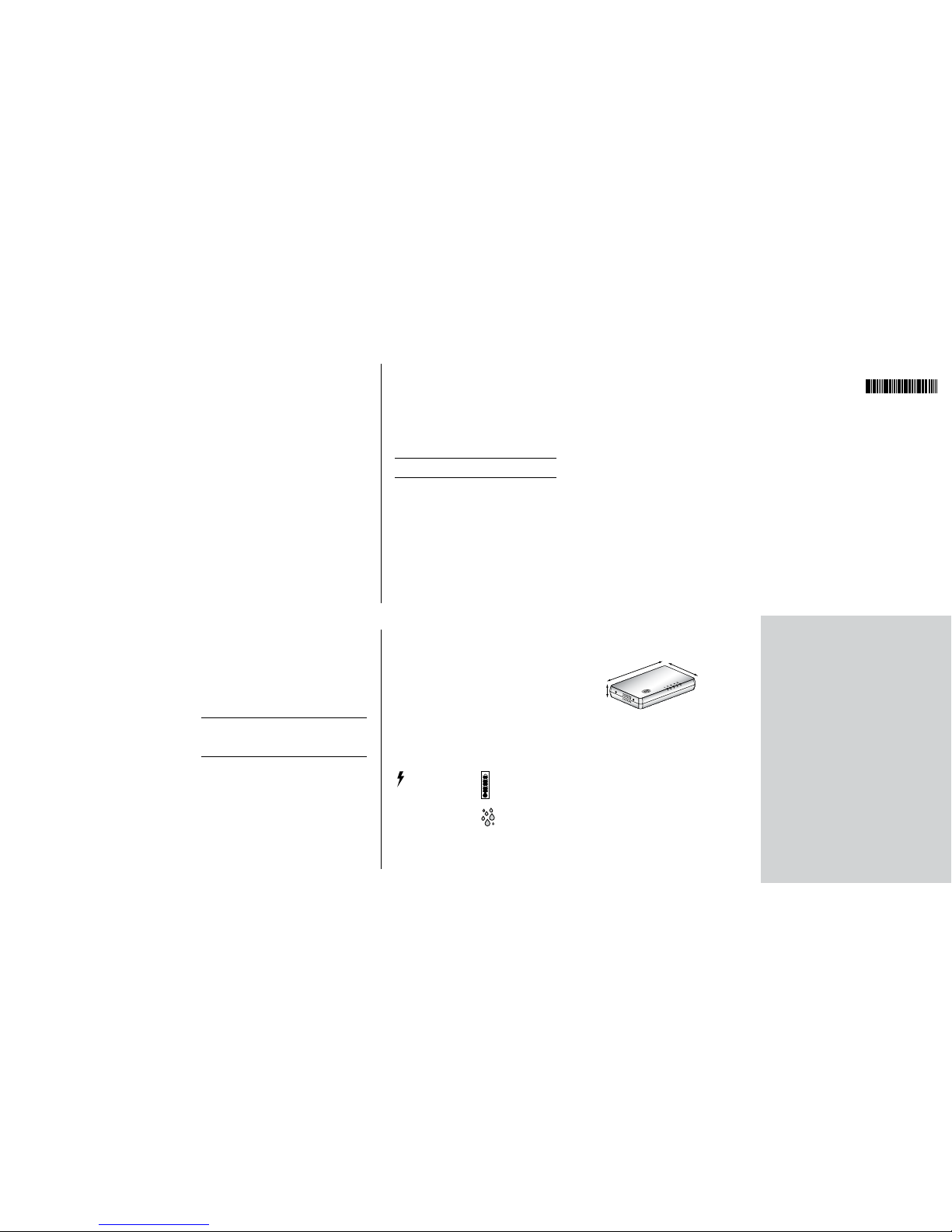
Dimensions
HP V1405-5G Switch
1 Height: 30 mm (1.18 in.)
2 Width: 178 mm (7.00 in.)
3 Depth: 108 mm (4.25 in.)
Weight: 275g (9.7 ounces)
HP V1405-5 Switch
1 Height: 30 mm (1.18 in.)
2 Width: 143 mm (5.60 in.)
3 Depth: 108 mm (4.25 in.)
Weight: 255g (8.99 ounces)
HP V1405-8G Switch
1 Height: 30 mm (1.18 in.)
2 Width: 178 mm (7.00 in.)
3 Depth: 108 mm (4.25 in.)
Weight: 310g (10.93 ounces)
HP V1405-8 Switch
1 Height: 30 mm (1.18 in.)
2 Width: 143 mm (5.60 in.)
3 Depth: 108 mm (4.25 in.)
Weight: 308g (10.87 ounces)
HP V1405-5 Switch (JD866A)
HP V1405-8 Switch (JD867A)
HP V1405-5G Switch (JD869A)
HP V1405-8G Switch (JD871A)
Installation Guide
Connecting Workstations
Twisted Pair (TP) Cables
Cables can be shielded (screened) or unshielded. Cables must be
Category 5 or above. HP recommends Category 5E or 6 cable for
Gigabit connections. The maximum length you can use is 100 m
(328 ft).
Twisted Pair (TP) cable is very easy to use. To connect a TP cable,
simply slot the connector into the relevant RJ-45 Port. When a
connector is fully in, its latch locks into place. To disconnect the
cable, push the connector’s latch in and remove it.
When one end of a TP cable is connected to the Switch and
the other end is connected to the network interface card of a
workstation or other device, the Switch will automatically detect
whether a straight-through or crossover cable is being used and
will compensate if required. The units will then autonegotiate to
determine the fastest possible link speed between them. This may
take a few seconds and the outcome will be reflected in the LEDs
on the front of the Switch.
If the equipment connected to the Switch does not support
autonegotiation or it has been disabled, it must be configured to
operate in half duplex mode.
Problem Solving
The Switch has been designed to aid you when detecting and
solving possible problems with your network. These problems are
rarely serious; the cause is usually a disconnected or damaged
cable, or incorrect configuration. If this section does not solve
your problem, contact your supplier for information on what to
do next.
Perform these actions first:
• Ensure all network equipment is powered on.
• Power each piece of network equipment off, wait about five
seconds and then power each one on.
NOTE: Do not power the Switch off and then immediately on. Wait about
five seconds between power cycles.
Check the following symptoms and solutions:
Power Status Logo not lit.
This is probably because the switch does not have power. Check
the following:
• Make sure the power lead from the power adapter is properly
connected and the cord is not damaged.
• Ensure the power adapter is correctly fitted into the power
outlet socket and that the socket switch is turned on if
applicable.
• Ensure you are using only the power adapter supplied with
the switch.
Port Status LED not lit for a port that has a TP cable connected.
After connection, it may take several seconds for the Port Status
LEDs to illuminate. The Port Status LED should turn Blue, for each
port that is connected.
If the Port Status LED is not lit after several seconds, ensure that
the connected device is powered on, that the TP cable is not
damaged and that it is correctly inserted at both ends.
You may find that a TP cable works when connected to the
Switch, but does not work if disconnected from the Switch and
connected to another device. This may be because the other
device does not have the automatic MDI/MDIX feature.
The Port Status LED is lit but the network performance of the
switch is poor.
The switch supports full-duplex autonegotiation. If the connected
device does not support autonegotiation, ensure it is configured
for half duplex operation only.
How Your Switch Can Be Used
Switching Overview
When a network of repeater hubs is in operation, any information
that is sent by the workstation is passed around the whole network
(regardless of the destination of the information). This can result
in a lot of unnecessary traffic that can slow the network down.
The Switch solves this problem because it “listens” to the network
and automatically learns what workstations can be reached
through its ports. It can then selectively pass on any information by
transmitting the traffic from the relevant port only. This operation is
called “switching”.
The Switch effectively divides up your network, localizing the
network traffic and passing on traffic as necessary. If you have any
high performance workstations that require a lot of bandwidth,
connect them directly to the Switch.
Traffic Prioritization (Gigabit Switch Only)
The Switch has a built in feature to aid network performance at
times of excessive load. It is called Priority Queuing. When a
packet is received, the Switch will examine it to see if it has been
priority encoded. If it has, the Switch will then read the priority
level and determine whether it should be directed through the
normal or high priority channel. This feature can be useful during
excessive loads, for example, when one type of traffic may require
priority over another.
Expanding Your Network
You can increase the number of workstations and other devices
that can connect to your network by adding switches. You can
connect a 10BASE-T, 100BASE-TX or 1000BASE-T to each port of
the Switch.
The Switch has automatic MDI/MDIX. Simply plug in the cable,
and the Switch will automatically detect which wiring practice has
been followed, and will compensate accordingly.
Checking Unit Connections
When you have connected all your units, power on the units and
the Switch. The Port Status LEDs for the ports you have used should
be lit. If they are not, check your connections.
Hewlett-Packard
3000 Hanover St.
Palo Alto, CA 94304, U.S.A.
Copyright © 2011 Hewlett-Packard Company. All rights reserved.
Microsoft, MS-DOS and Windows are registered trademarks of
Micorsoft Corporation.
All other company and product names may be trademarks of their
respective companies.
Part No: 5998-2274
Published: May 2011
Connecting 10BASE-T/100BASE-TX/1000BASE-T
Networks
The ports can each be connected to an Ethernet network. If you
have various connection speeds in your network, you can join
them together using the Switch allowing all your workstations
to communicate. For example, by connecting one of the ports
to a server, all the workstations connected to the server can
communicate with devices connected to the Switch, significantly
increasing the size of your network.
NOTE: The Fast Ethernet Switch models can be used to connect to
1000BASE-T (Gigabit) networks.However, the speed of connection between
the Fast Ethernet Switch and the 1000BASE-T network will operate at 100
Mbps. Ensure that the 1000BASE-T network equipment is configured for
auto-negotiation to ensure the link operates correctly.
1
3
2
* 5 9 9 8 - 2 2 7 4 *
5998-2274
Page 2
Introduction
Thank you for purchasing this Switch. This high quality
Switch is an easy, efficient way of creating a network or
expanding an existing network. The Switch’s Gigabit/Fast
Ethernet ports (depending on model) provide support for
bandwidth intensive applications, and allow highspeed
connections to servers, and to the rest of the network.
Your package contains:
• Switch
• Power adapter for use with the V1405-5G and 1405-8G,
or power cord for use with the V1405-5 and V1405-8
• Four rubber feet
• This installation guide
• Support and Safety Information sheet
• Warranty flyer
NOTE: This guide will use the terms Switch 5/8 when referring to HP V14055/8 Switch and Gigabit Switch 5/8 when referring to HP V1405-5G/8G
Switch.
WARNING: Please read the ‘Important Safety Information’ section in
the Support and Safety Information sheet before you start.
VORSICHT: Lesen Sie zuerst im Informationsblatt mit Support- und
Sicherheitshinweisen den Abschnitt „Wichtige Sicherheitshinweise“.
ADVERTENCIA: Antes de empezar, lea la sección “Información
importante sobre seguridad” de la hoja Información de soporte y
seguridad.
AVISO: Leia a seção ‘Informações Importantes sobre Segurança’ na
folha Informações de Suporte e Segurança antes de você começar.
AVERTISSEMENT: Avant de commencer, veuillez prendre
connaissance des informations de la section «Informations
importantes sur la sécurité» de la fiche Informations relatives à
l›assistance et à la sécurité.
Configuration
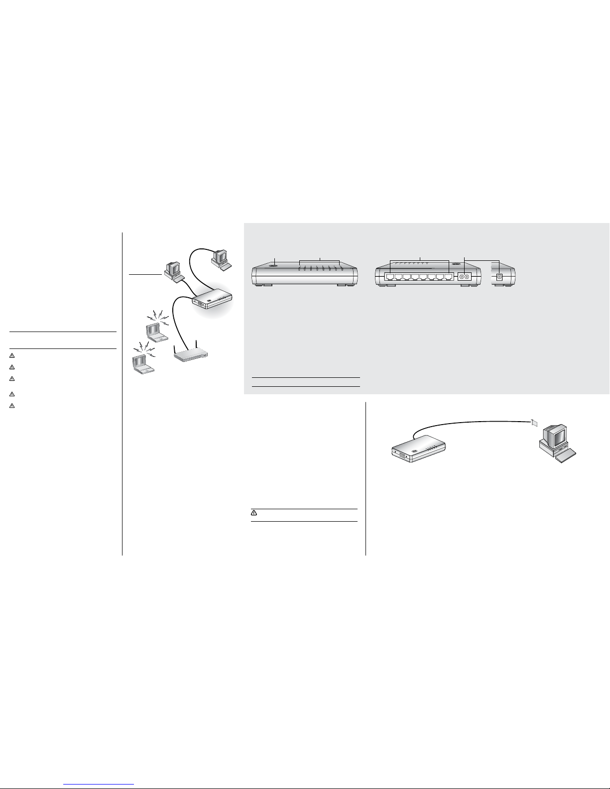
1 Illuminated Power Status Logo (White)
Indicates that the Switch is powered on. If the LED is off, there
may be a problem. Refer to Problem Solving.
2 Five/Eight Port Status LEDs (Blue)
If the LED is on, the link between the port and the next piece
of equipment is OK. If the LED is flashing, the link is OK and
data is being transmitted or received. If the LED is off, nothing
is connected or the connected device is turned off, or there is
a problem with the connection (refer to the Problem Solving
section).
NOTE: Product may vary from model shown.
3 10BASE-T/100BASE-TX Ports *(Switch 5/Switch 8)
Use suitable TP cable (see Section 3) with RJ-45 connectors.
You can connect your Switch to a workstation, or any
other piece of equipment that has 10BASE-T/ 100BASE-TX
connectivity.
10BASE-T/100BASE-TX/1000BASE-T Ports*
(GIgabit Switch 5/Gigabit Switch 8)
Use suitable TP cable (see Section 3) with RJ-45 connectors.
You can connect your Switch to a workstation, or any
other piece of equipment that has 10BASE-T/100BASETX/1000BASE-T connectivity.
* Each port is capable of autosensing for 10 Mbps, 100
Mbps or 1000 Mbps operation.
All ports have an automatic MDI/MDIX feature, which means
either straight-through or crossover cable can be used to
connect to any port.
4 Power Adapter Socket
Only use the power adapter that is supplied with the Switch.
About Your HP V1405-8 Switch
Front Rear
1
2
3
1
3 42
Sample configuration with Switch or Gigabit Switch.
Desktop PC
Switch: Desktop PC
Gigabit Switch:
Workstation requiring
High Bandwith
Connection
Gigabit Switch only:
1000 Mbps
Connections
Switch/
Gigabit Switch
Wireless 11g
Access Point
Positioning Your Switch
When positioning your Switch, ensure:
• It is out of direct sunlight and away from sources of heat
• Cabling is away from power lines, fluorescent lighting fixtures,
and sources of electrical noise such as radios, transmitters and
broadband amplifiers
• Water or moisture cannot enter the case of the unit
• Air flow around the unit and through the vents in the side of
the case is not restricted. It is recommended that you provide a
minimum of 25 mm (1 in.) clearance
Using the Rubber Feet
Use the four self-adhesive rubber feet to prevent your Switch from
moving around on your desk, or when stacking with other units.
Only stick the feet to the marked areas at each corner on the
underside of your Switch.
Wall Mounting
There are two slots on the underside of the Switch that can be used
for wall mounting. The Switch must be mounted with the LEDs facing
upwards.
Before you Install Your Switch
Unit Connections
To connect other units (such as gateways or other switches) to your
Switch you need:
1 One suitable Twisted Pair cable for each workstation.
HP recommends Category 5E or 6 cable for Gigabit connections.
Workstation Connections
To connect workstations or other equipment (such as servers)
directly to your Switch, you need:
1 One suitable Twisted Pair cable for each workstation.
2 One adapter card for each workstation to be connected to
a port on the Switch. The adapter card must be capable
of communicating at the required connection speed. For
example, if you want to use a Gigabit connection, you must
install a 1000BASE-T adapter card.
3 An operating system (for example, Netware, Windows, MAC
or Linux) with network support configured, running on your
workstation.
Mounting Instructions for Cement Walls
Make two holes 124 mm (4.9 in.) apart and insert two nylon or
similar screw anchors that are suitable for the wall construction.
Fix two suitable screws into the anchors, leaving their heads 3 mm
(0.12 in.) clear of the wall surface. The screws should be at least
30 mm (1.2 in.) long,
Remove any connections in the Switch and locate it over the screw
heads. When in line, gently push the Switch on to the wall and
move it downwards to secure.
Mounting Instructions for Wood Walls
Make two holes 124 mm (4.9 in.) apart.
Fix two suitable screws directly into the wall, leaving their heads
3 mm (0.12 in.) clear of the wall surface. The screws should be at
least 20 mm (0.75 in.) long.
Remove any connections in the Switch and locate it over the screw
heads. When in line, gently push the Switch on to the wall and
move it downwards to secure.
CAUTION: When making connections, be careful not to push the
Switch up and off the wall.
 Loading...