

HP TippingPoint, TippingPoint 110, TippingPoint 10, TippingPoint 330 Hardware Installation And Safety Manual
Page 1

HP TippingPoint
TippingPoint 10/110/330 Hardware Installation
and Safety Guide
Abstract
This document describes safety guidelines and procedures for hardware installation for the TippingPoint 10,
TippingPoint 110, and TippingPoint 330.
*5998-2868*
5998-2868
Part number: 5998-2868
Edition: October 2013
Page 2

Legal and notice information
© Copyright 2010-2013 Hewlett-Packard Development Company, L.P.
Hewlett-Packard Company makes no warranty of any kind with regard to this material, including, but not limited to, the implied warranties of
merchantability and fitness for a particular purpose. Hewlett-Packard shall not be liable for errors contained herein or for incidental or consequential
damages in connection with the furnishing, performance, or use of this material.
This document contains proprietary information, which is protected by copyright. No part of this document may be photocopied, reproduced, or
translated into another language without the prior written consent of Hewlett-Packard. The information is provided “as is” without warranty of any
kind and is subject to change without notice. The only warranties for HP products and services are set forth in the express warranty statements
accompanying such products and services. Nothing herein should be construed as constituting an additional warranty. HP shall not be liable for
technical or editorial errors or omissions contained herein.
TippingPoint® , the TippingPoint logo, and Digital Vaccine® are registered trademarks of Hewlett-Packard. All other company and product names
may be trademarks of their respective holders. All rights reserved. This document contains confidential information, trade secrets or both, which are
the property of Hewlett-Packard No part of this documentation may be reproduced in any form or by any means or used to make any derivative
work (such as translation, transformation, or adaptation) without written permission from Hewlett-Packard or one of its subsidiaries.
Adobe® and Acrobat® are trademarks of Adobe Systems Incorporated.
Intel and Itanium are trademarks or registered trademarks of Intel Corporation or its subsidiaries in the United States and other countries.
Microsoft, Windows, Windows NT, and Windows XP are U.S. registered trademarks of Microsoft Corporation.
Oracle® is a registered U.S. trademark of Oracle Corporation, Redwood City, California.
UNIX® is a registered trademark of The Open Group.
Printed in the US.
TippingPoint 10/110/330 Hardware Installation and Safety Guide
Page 3

Table of Contents
About This Guide . . . . . . . . . . . . . . . . . . . . . . . . . . . . . . . . . . . . . . . . . . . . . . . . . . . . . . 5
Overview. . . . . . . . . . . . . . . . . . . . . . . . . . . . . . . . . . . . . . . . . . . . . . . . . . . . . . . . . . . . . . . . . . . . . . 5
Target Audience . . . . . . . . . . . . . . . . . . . . . . . . . . . . . . . . . . . . . . . . . . . . . . . . . . . . . . . . . . . . . . . . . 5
Conventions. . . . . . . . . . . . . . . . . . . . . . . . . . . . . . . . . . . . . . . . . . . . . . . . . . . . . . . . . . . . . . . . . . . . 5
Typefaces . . . . . . . . . . . . . . . . . . . . . . . . . . . . . . . . . . . . . . . . . . . . . . . . . . . . . . . . . . . . . . . . . . . 5
Document Messages . . . . . . . . . . . . . . . . . . . . . . . . . . . . . . . . . . . . . . . . . . . . . . . . . . . . . . . . . . . 6
Product Documentation . . . . . . . . . . . . . . . . . . . . . . . . . . . . . . . . . . . . . . . . . . . . . . . . . . . . . . . . . . . . 7
Customer Support . . . . . . . . . . . . . . . . . . . . . . . . . . . . . . . . . . . . . . . . . . . . . . . . . . . . . . . . . . . . . . . . 7
Contact Information . . . . . . . . . . . . . . . . . . . . . . . . . . . . . . . . . . . . . . . . . . . . . . . . . . . . . . . . . . . . 7
1 System Overview . . . . . . . . . . . . . . . . . . . . . . . . . . . . . . . . . . . . . . . . . . . . . . . . . . . . 1
Overview. . . . . . . . . . . . . . . . . . . . . . . . . . . . . . . . . . . . . . . . . . . . . . . . . . . . . . . . . . . . . . . . . . . . . . 1
TippingPoint Architecture . . . . . . . . . . . . . . . . . . . . . . . . . . . . . . . . . . . . . . . . . . . . . . . . . . . . . . . . . . . 1
Security Management System (SMS) . . . . . . . . . . . . . . . . . . . . . . . . . . . . . . . . . . . . . . . . . . . . . . . . . . . 2
SMS Server. . . . . . . . . . . . . . . . . . . . . . . . . . . . . . . . . . . . . . . . . . . . . . . . . . . . . . . . . . . . . . . . . . 2
SMS Client . . . . . . . . . . . . . . . . . . . . . . . . . . . . . . . . . . . . . . . . . . . . . . . . . . . . . . . . . . . . . . . . . . 2
Intrusion Prevention System Devices (IPS) . . . . . . . . . . . . . . . . . . . . . . . . . . . . . . . . . . . . . . . . . . . . . . . . 3
IPS Local Clients . . . . . . . . . . . . . . . . . . . . . . . . . . . . . . . . . . . . . . . . . . . . . . . . . . . . . . . . . . . . . . 3
Core Controller . . . . . . . . . . . . . . . . . . . . . . . . . . . . . . . . . . . . . . . . . . . . . . . . . . . . . . . . . . . . . . . . . 4
High Availability. . . . . . . . . . . . . . . . . . . . . . . . . . . . . . . . . . . . . . . . . . . . . . . . . . . . . . . . . . . . . . . . . 4
Threat Suppression Engine. . . . . . . . . . . . . . . . . . . . . . . . . . . . . . . . . . . . . . . . . . . . . . . . . . . . . . . . . . 4
Threat Management Center . . . . . . . . . . . . . . . . . . . . . . . . . . . . . . . . . . . . . . . . . . . . . . . . . . . . . . . . . 5
2 TippingPoint Hardware Safety and Compliance . . . . . . . . . . . . . . . . . . . . . . . . . . . . . . . 7
Overview. . . . . . . . . . . . . . . . . . . . . . . . . . . . . . . . . . . . . . . . . . . . . . . . . . . . . . . . . . . . . . . . . . . . . . 7
Safety and Compliance Requirements . . . . . . . . . . . . . . . . . . . . . . . . . . . . . . . . . . . . . . . . . . . . . . . . . . 7
Safety Guidelines and Warnings . . . . . . . . . . . . . . . . . . . . . . . . . . . . . . . . . . . . . . . . . . . . . . . . . . . 7
Cautions. . . . . . . . . . . . . . . . . . . . . . . . . . . . . . . . . . . . . . . . . . . . . . . . . . . . . . . . . . . . . . . . . . . . 7
Warnings . . . . . . . . . . . . . . . . . . . . . . . . . . . . . . . . . . . . . . . . . . . . . . . . . . . . . . . . . . . . . . . . . . . 8
Rack and Clearance Requirements . . . . . . . . . . . . . . . . . . . . . . . . . . . . . . . . . . . . . . . . . . . . . . . . . . . 10
Ventilation and Location . . . . . . . . . . . . . . . . . . . . . . . . . . . . . . . . . . . . . . . . . . . . . . . . . . . . . . . . . . 10
Environmental Requirements. . . . . . . . . . . . . . . . . . . . . . . . . . . . . . . . . . . . . . . . . . . . . . . . . . . . . . . . 11
Reliable Earthing . . . . . . . . . . . . . . . . . . . . . . . . . . . . . . . . . . . . . . . . . . . . . . . . . . . . . . . . . . . . . . . 11
ESD Requirements. . . . . . . . . . . . . . . . . . . . . . . . . . . . . . . . . . . . . . . . . . . . . . . . . . . . . . . . . . . . . . . 11
Hot Swapping Guidelines . . . . . . . . . . . . . . . . . . . . . . . . . . . . . . . . . . . . . . . . . . . . . . . . . . . . . . . . . 11
Unpack the Product . . . . . . . . . . . . . . . . . . . . . . . . . . . . . . . . . . . . . . . . . . . . . . . . . . . . . . . . . . . . . 12
3 TippingPoint 10 Overview. . . . . . . . . . . . . . . . . . . . . . . . . . . . . . . . . . . . . . . . . . . . . 13
Overview. . . . . . . . . . . . . . . . . . . . . . . . . . . . . . . . . . . . . . . . . . . . . . . . . . . . . . . . . . . . . . . . . . . . . 13
Chassis Overview . . . . . . . . . . . . . . . . . . . . . . . . . . . . . . . . . . . . . . . . . . . . . . . . . . . . . . . . . . . . . . . 13
LEDs. . . . . . . . . . . . . . . . . . . . . . . . . . . . . . . . . . . . . . . . . . . . . . . . . . . . . . . . . . . . . . . . . . . . . . 14
Technical Specifications. . . . . . . . . . . . . . . . . . . . . . . . . . . . . . . . . . . . . . . . . . . . . . . . . . . . . . . . . . . 15
Hardware Specifications. . . . . . . . . . . . . . . . . . . . . . . . . . . . . . . . . . . . . . . . . . . . . . . . . . . . . . . . 15
Software Specifications . . . . . . . . . . . . . . . . . . . . . . . . . . . . . . . . . . . . . . . . . . . . . . . . . . . . . . . . 15
Hardware Installation and Configuration . . . . . . . . . . . . . . . . . . . . . . . . . . . . . . . . . . . . . . . . . . . . . . . 16
Install the Chassis . . . . . . . . . . . . . . . . . . . . . . . . . . . . . . . . . . . . . . . . . . . . . . . . . . . . . . . . . . . . 16
Connect cables . . . . . . . . . . . . . . . . . . . . . . . . . . . . . . . . . . . . . . . . . . . . . . . . . . . . . . . . . . . . . . 20
Connect the Power . . . . . . . . . . . . . . . . . . . . . . . . . . . . . . . . . . . . . . . . . . . . . . . . . . . . . . . . . . . 21
Setup Wizard . . . . . . . . . . . . . . . . . . . . . . . . . . . . . . . . . . . . . . . . . . . . . . . . . . . . . . . . . . . . . . . 21
USB Update and Restore . . . . . . . . . . . . . . . . . . . . . . . . . . . . . . . . . . . . . . . . . . . . . . . . . . . . . . . 22
4 TippingPoint 110/330 Overview . . . . . . . . . . . . . . . . . . . . . . . . . . . . . . . . . . . . . . . . 23
Overview. . . . . . . . . . . . . . . . . . . . . . . . . . . . . . . . . . . . . . . . . . . . . . . . . . . . . . . . . . . . . . . . . . . . . 23
Chassis Overview . . . . . . . . . . . . . . . . . . . . . . . . . . . . . . . . . . . . . . . . . . . . . . . . . . . . . . . . . . . . . . . 23
TippingPoint 10/110/330 Hardware Installation and Safety Guide 3
Page 4

LEDs. . . . . . . . . . . . . . . . . . . . . . . . . . . . . . . . . . . . . . . . . . . . . . . . . . . . . . . . . . . . . . . . . . . . . . 24
Technical Specifications. . . . . . . . . . . . . . . . . . . . . . . . . . . . . . . . . . . . . . . . . . . . . . . . . . . . . . . . . . . 25
Hardware Specifications. . . . . . . . . . . . . . . . . . . . . . . . . . . . . . . . . . . . . . . . . . . . . . . . . . . . . . . . 25
Software Specifications . . . . . . . . . . . . . . . . . . . . . . . . . . . . . . . . . . . . . . . . . . . . . . . . . . . . . . . . 26
Hardware Installation and Configuration . . . . . . . . . . . . . . . . . . . . . . . . . . . . . . . . . . . . . . . . . . . . . . . 26
Install the Chassis . . . . . . . . . . . . . . . . . . . . . . . . . . . . . . . . . . . . . . . . . . . . . . . . . . . . . . . . . . . . 26
Connect cables . . . . . . . . . . . . . . . . . . . . . . . . . . . . . . . . . . . . . . . . . . . . . . . . . . . . . . . . . . . . . . 26
Connect the Power . . . . . . . . . . . . . . . . . . . . . . . . . . . . . . . . . . . . . . . . . . . . . . . . . . . . . . . . . . . 27
Setup Wizard . . . . . . . . . . . . . . . . . . . . . . . . . . . . . . . . . . . . . . . . . . . . . . . . . . . . . . . . . . . . . . . 28
USB Update and Restore . . . . . . . . . . . . . . . . . . . . . . . . . . . . . . . . . . . . . . . . . . . . . . . . . . . . . . . 28
A Connector and Pinout Specifications . . . . . . . . . . . . . . . . . . . . . . . . . . . . . . . . . . . . . . 29
RJ-45 (COM) Console . . . . . . . . . . . . . . . . . . . . . . . . . . . . . . . . . . . . . . . . . . . . . . . . . . . . . . . . . . . . 29
RJ-45 Ethernet Connectors . . . . . . . . . . . . . . . . . . . . . . . . . . . . . . . . . . . . . . . . . . . . . . . . . . . . . . . . . 29
Index . . . . . . . . . . . . . . . . . . . . . . . . . . . . . . . . . . . . . . . . . . . . . . . . . . . . . . . . . . . . . 31
<Manual Title> <Manual Subtitle> <manual type> 4
Page 5

About This Guide
Explains intended audience, where related information is located, and how to obtain
customer support.
Overview
Welcome to the HP TippingPoint N-Platform Hardware Installation and Safety Guide.
This section includes the following items:
• ”Target Audience” on page 5
• ”Conventions” on page 5
• ”Product Documentation” on page 7
• ”Customer Support” on page 7
Target Audience
The intended audience includes technicians and maintenance personnel responsible for installing,
configuring, and maintaining TippingPoint security systems and associated devices. Users should be
familiar with networking concepts and the following standards and protocols:
• TCP/IP
• UDP
• ICMP
• Ethernet
• Simple Network Time Protocol (SNTP)
• Simple Mail Transport Protocol (SNMP)
• Simple Network management Protocol (SNMP)
Conventions
This guide uses the following document conventions.
• Typefaces, page 5
• Document Messages, page 6
Typefaces
TippingPoint publications use the following typographic conventions for structuring information:
TippingPoint 10/110/330 Hardware Installation and Safety Guide 5
Page 6

Table 1 Document Typographic conventions
Convention Element
Medium blue text: Figure 1
Medium blue, underlined text
(http://www.hp.com)
Bold font • Key names
Italics font Text emphasis, important terms, variables, and publication titles.
Monospace font • File and directory names
Monospace, italic font • Code variables
Monospace, bold font Emphasis of file and directory names, system output, code, and text
Document Messages
Document messages are special text that is emphasized by font, format, and icons. This <manual type>
contains the following types of messages:
Cross-reference links and e-mail addresses
Web site addresses
• Text typed into a GUI element, such as into a box
• GUI elements that are clicked or selected, such as menu and list
items, buttons, and check boxes. Example: Click
• System output
• Code
• Text typed at the command-line
• Command-line variables
typed at the command line
OK to accept.
• Warning
• Caution
• Note
• Tip
WARNING! Warning notes alert you to potential danger of bodily harm or other potential harmful
consequences.
CAUTION: Caution notes provide information to help minimize risk, for example, when a failure to follow
directions could result in damage to equipment or loss of data.
NOTE: Notes provide additional information to explain a concept or complete a task. Notes of specific
importance in clarifying information or instructions are denoted as such.
IMPORTANT: Another type of note that provides clarifying information or specific instructions.
TIP: Tips provide helpful hints and shortcuts, such as suggestions about how you can perform a task more
easily or more efficiently.
6
Page 7

Product Documentation
TippingPoint Systems have a full set of documentation. For the most current documentation, check the Threat
Management Center (TMC) Web site at https://tmc.tippingpoint.com
Customer Support
TippingPoint is committed to providing quality customer support to all of its customers. Each customer is
provided with a customized support agreement that provides detailed customer and support contact
information.
For the most efficient resolution of your problem, take a moment to gather some basic information from your
records and from your system before contacting customer support, including your customer number.
Information Location
Your customer number You can find this number on your Customer Support
Your device serial number You can find this information on the bottom of the server
.
Agreement and on the shipping invoice that came with your
TippingPoint system.
chassis. Also, from the TippingPoint CLI, you can run the
show version
command.
Your device version number From the TippingPoint CLI, you can run the show version
Contact Information
For additional information or assistance, contact the HP TippingPoint Technical Assistance Center (TAC):
Telephone
North America: +1 866 681 8324
International: +1 512 681 8324
For a list of international toll-free contact numbers, consult the following web page:
https://tmc.tippingpoint.com/TMC/Content/support/Support_Contacts
Online Support Request
1. Log on to the TippingPoint Threat Management Center (TMC) with your HP Passport credentials.
NOTE: If you don’t have HP Passport (HPP) credentials, access the TMC and on the Login page, select the
New User Registration option to register for login credentials. If you are an existing registered TMC user
and you have not updated your TMC account to an HPP account, you must log on using your email
address registered on the TMC and reset your password. To reset your password, access the TMC and on
the Login page, select Forgot Password and set a new password.
command.
2. In the menu bar click Support > Support Request.
3. Complete the information required in the Support Request form and submit the form.
tippingpoint.support@hp.com
TippingPoint 10/110/330 Hardware Installation and Safety Guide 7
Page 8

8
Page 9
1System Overview
The TippingPointTM system is a high-speed, comprehensive security system that includes the Intrusion
Prevention System (IPS),
System Appliance
TM
TM
Local Security Manager (LSM), Digital Vaccine™, the Security Management
, and the Core Controller.
Overview
Enterprise security schemes once consisted of a conglomeration of disparate, static devices from multiple
vendors. Today, TippingPoint’s security system provides the advantages of a single, integrated, highly
adaptive security system that includes powerful hardware and an intuitive management interface.
This section includes the following topics:
• ”TippingPoint Architecture” on page 1
• ”Security Management System (SMS)” on page 2
• ”Intrusion Prevention System Devices (IPS)” on page 3
• ”Core Controller” on page 4
• ”High Availability” on page 4
• ”Threat Suppression Engine” on page 5
• ”Threat Management Center” on page 5
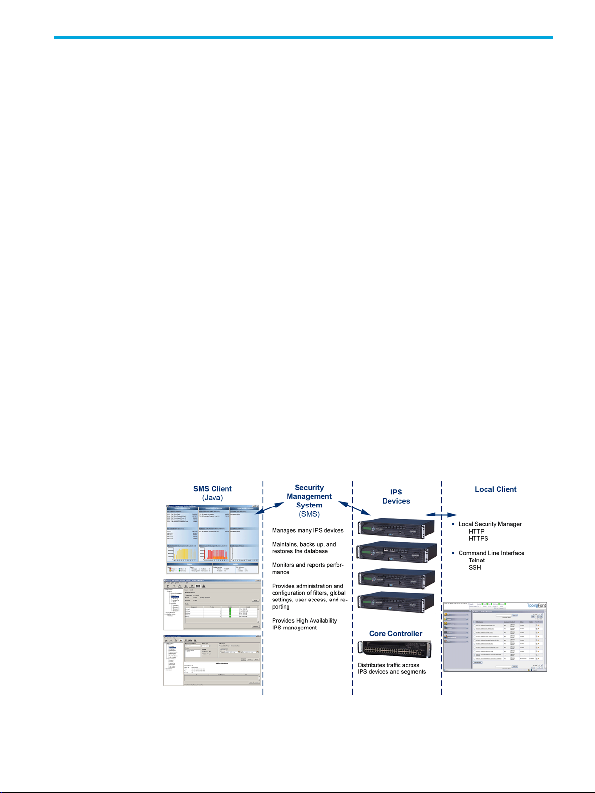
TippingPoint Architecture
The TippingPoint System uses a flexible architecture that consists of a Java-based SMS Client, SMS
Management Server, IPS device(s), and Local Clients including the Local Security Manager (LSM) and
Command Line Interface (CLI). The system may also include the Core Controller, a hardware appliance that
balances traffic loads for one or more IPSes. The following diagram provides an overview of the
architecture:
Figure 1-1 TippingPoint Architecture
TippingPoint 10/110/330 Hardware Installation and Safety Guide 1
Page 10

Security Management System (SMS)
The SMS core components include:
• SMS Secure Server —hardware appliance for managing multiple devices
• SMS Home Page — web-based interface with links to current Client software, documentation, and the
Threat Management Center
• SMS Management Client — Java-based application for Windows or Linux workstations used to manage
your TippingPoint system
• Graphical User Interface (GUI)
• Dashboard
• Command Line Interface (CLI)
The SMS communicates with managed devices that are installed in your network.
The SMS architecture also includes the following components:
• Threat Management Center (TMC) — Centralized service center that monitors global threats and
distributes up-to-date attack filter packages, software updates, and product documentation.
• Digital Vaccine (DV) — Update service that includes up-to-date filter packages for protecting your
network
• Managed Devices — TippingPoint IPS or Core Controller devices that are installed in your network
SMS Server
The SMS Server is an enterprise-class management platform that provides centralized administration,
configuration, monitoring and reporting for well over a hundred TippingPoint IPS devices. The SMS
provides the following functionality:
• Enterprise-wide device status and behavior monitoring — Stores logs and device status
• IPS networking and configuration — Stores device information and configures devices
• Filter customization — Stores filter customizations in profiles as maintained by the SMS client.
• Filter and software distribution — Monitors and maintains the distribution and import of filters,
SMS Client
The TippingPoint Security Management System (SMS) client provides services and functions to monitor,
manage, and configure the entire TippingPoint system. This client is a Java-based application installed and
accessed on a computer running the appropriate operating system. Each user receives a specific user level
with enhanced security measures to protect access and configuration of the system.
information, manages updates, and monitors filter, device, software, and network status.
according to the settings that are modified, imported, or distributed by clients. These settings affect the
flow and detection of traffic according to device, segment, or segment group.
These settings are distributed and imported to devices, which can be reviewed and modified by local
clients. If a device is managed by the SMS Server, the local clients cannot modify settings.
Digital Vaccine packages, and software for the TippingPoint Operating System and SMS Client. The
SMS client and Central Management Server can distribute these packages according to segment group
settings. The Central Management Server maintains a link to the Threat Management Center (TMC) for
downloading and installing package updates.
You can monitor the entire TippingPoint system through the SMS client on a computer with the following
requirements:
• One of the following operating systems:
• Windows 98, 2nd edition
• Windows NT, Service Pack 5 or later
• Windows 2000, Service Pack 3 or later
•Windows XP
•Windows 7
2 System Overview
Page 11

• Apple
•Red Hat Linux
• One of the following browsers:
• Microsoft Internet Explorer, version 6.0 or higher
•Firefox
• Safari
The SMS features a policy-based operational model for scalable and uniform enterprise management. It
enables behavior and performance analysis with trending reports, correlation and real-time graphs including reports on all, specific, and top attacks and their sources and destinations as well as all, specific,
and top peers and filters for misuse and abuse (peer-to-peer piracy) attacks. You can create, save, and
schedule reports using report templates. All reports are run against system and audit logs stored for each
device managed by the system. These logs detail triggered filters. You can modify, update, and control
distribution of these filters according to segment groups for refined intrusion prevention.
The SMS dashboard provides at-a-glance monitors, with launch capabilities into the targeted management
applications that provide global command and control of TippingPoint. It displays the entries for the top 5
filters triggered over the past hour in various categories, a graph of triggered filters over the past 24 hours,
the health status of devices, and update versions for software of the system. Through the Dashboard, you
gain an overview of the current performance of your system, including notifications of updates and
possible issues with devices monitored by the SMS.
Intrusion Prevention System Devices (IPS)
Intrusion Prevention System (IPS) devices protect your network with the Threat Suppression Engine (TSE) by
scanning, detecting, and responding to network traffic according to the filters, action sets, and global
settings maintained on each device by a client.
Each device provides intrusion prevention for your network according to the number of network
connections and hardware capabilities. IPS devices also have built-in intrinsic high-availability features,
guaranteeing that the network keeps running in the event of system failure.
TippingPoint Intrusion Prevention Systems are optimized to provide high resiliency, high availability security
for remote branch offices, small-to-medium and large enterprises and collocation facilities. Each
TippingPoint can protect network segments from both external and internal attacks.
Multiple TippingPoint devices can be deployed to extend this unsurpassed protection to hundreds of
enterprise zones. You can monitor and manage the devices by using the local client available on each
device, or by using the SMS client to monitor and manage well over a hundred devices. The TippingPoint
660N/1400N/2500N/5100N support IPv6, tunneling (including GRE and multi-layer tunnels), and
inspection bypass rules for trusted traffic.
IPS Local Clients
The TippingPoint System provides various points of interaction, management, and configuration of the
intrusion prevention system. The clients include graphical user interfaces (GUI) and command line
interfaces (CLI). These clients include the following:
• Local Security Manager (LSM) — Web-based GUI for managing one IPS device. The LSM provides
HTTP and HTTPS (secure management) access. This access requires access from a supported web
browser (Internet Explorer, Mozilla Firefox, and Netscape). Using the LSM, you have a graphical
display for reviewing, searching, and modifying settings. The GUI interface also provides reports to
monitor the device traffic, triggered filters, and packet statistics.
• Command Line Interface (CLI) — Command line interface for reviewing and modifying settings on the
device. The CLI is accessible through Telnet and SSH (secure access).
• LCD Panel — Several IPS TippingPoint devices provide an LCD panel to view, configure and modify
some device settings.
TippingPoint 10/110/330 Hardware Installation and Safety Guide 3
Page 12

Core Controller
The TippingPoint Core Controller is a hardware-based device that enables inspection of up to 20 Gbps of
traffic by sending the traffic to as many as 24 IPS device segments. The CoreController can control traffic
across its three 10GbE network segment pairs and across multiple TippingPoint E-Series IPS devices. IPS
devices are connected by 1GbE uplinks, and each packet that is received on a 10GbE CoreController
interface passes through a load balancer that then determines the IPS connection to use for transmitting the
packet.
The Core Controller provides:
• 10GbE bidirectional traffic inspection and policy enforcement
• High Availability with an optional Smart ZPHA module
• Central management through the SMS
NOTE: The Core Controller can be used with the 2400E and 5000E IPS devices, and with all N-Platform
and NX-Platform devices.
High Availability
TippingPoint devices are designed to guarantee that your network traffic always flows at wire speeds in the
event of internal device failure. The TippingPoint System provides Network High Availability settings for
Intrinsic Network HA (INHA) and Transparent Network HA (TNHA). These options enact manually or
automatically, according to settings you enter using the clients (LSM and SMS) or LCD panel for IPS
devices. Zero-Power High Availability (ZPHA) is available for the IPS as an external modular device, as
optional bypass I/O modules on NX-Platform devices, and for the Core Controller as an optional Smart
ZPHA module.
The IPS uses INHA for individual device deployment and TNHA for devices deployed in redundant
configurations in which one device takes over for another in the event of system failure. With INHA, a
failure puts the device into Layer-2 Fallback mode and permits or blocks traffic on each segment. In TNHA,
multiple IPS devices are synchronized so that when one device experiences a system failure, traffic is routed
to the other device with no interruption in intrusion prevention services.
SMS high availability provides continuous administration through an active-passive SMS system
configuration. A passive SMS is configured, synchronized with the active system, and waits in standby
mode and monitors the health of the active system. If the health or communications check fails, the passive
SMS will be activated.
The ZPHA modular device can be attached to an IPS to route traffic in the event of power loss. Smart ZPHA
modules, which are wired into the device, and bypass I/O modules, which are installed directly into
NX-Platform devices, perform the same function.
Threat Suppression Engine
The Threat Suppression Engine (TSE) is a line-speed hardware engine that contains all the functions
needed for Intrusion Prevention, including IP defragmentation, TCP flow reassembly, statistical analysis,
traffic shaping, flow blocking, flow state tracking and application-layer parsing of over 170 network
protocols.
The TSE reconstructs and inspects flow payloads by parsing the traffic at the application layer. As each
new packet of the traffic flow arrives, the engine re-evaluates the traffic for malicious content. The instant
the engine detects malicious traffic, it blocks all current and all subsequent packets pertaining to the traffic
flow. The blocking of the traffic and packets ensures that the attack never reaches its destination.
The combination of high-speed network processors and custom chips provide the basis for IPS technology.
These highly specialized traffic classification engines enable the IPS to filter with extreme accuracy at
gigabit speeds and microsecond latencies. Unlike software-based systems whose performance is affected
4 System Overview
Page 13

by the number of filters installed, the highly-scalable capacity of the hardware engine allows thousands of
filters to run simultaneously with no impact on performance or accuracy.
Threat Management Center
The Threat Management Center (TMC) is a centralized service center that monitors global threats and
distributes up-to-date attack filter packages, software updates, and product documentation.
The Threat Management Center (TMC) collects threat information and creates Digital Vaccine packages
that are made available on the TMC web site. The packages include filters that block malicious traffic and
attacks on your network. The filters provide the following protections:
• Application Protection — Defend against known and unknown exploits that target applications and
operating systems:
• Attack Protection filters — Detect and block traffic known to be malicious, suspicious, and to have
known security implications. These filters include the following: Vulnerabilities and Exploits filters.
• Security Policy filters — Detect and block traffic that may or may not be malicious. This traffic may
be different in its format or content from standard business practice, aimed at specific software or
operating systems, or contrary to your company’s security policies.
• Reconnaissance filters — Detect and block scans, sweeps, and probes for vulnerabilities and
information about your network. These filters include the following: Probes and Sweeps/Scans
filters.
• Informational filters — Detect and block classic Intrusion Detection System (IDS) infiltration
• Infrastructure Protection — Protect network bandwidth and network infrastructure elements such as
routers and firewalls from attack using a combination of filter types:
• Advanced DDoS filters — Available on the 2400E and 5000E. Detect and block denial of service
and flood requests, such as SYN Requests, that can overwhelm a system.
• Network Equipment Protection filters — Protect networked equipment from attacks
• Traffic Normalization filters — Detect and block abnormal or malicious traffic
• Performance Protection — Allow key applications to have prioritized bandwidth access setting that
ensure mission critical applications have adequate performance during times of high congestion:
• Misuse and Abuse filters — Protect the resources and usage of file sharing across networks and
personal computers. These filters protect peer-to-peer services.
• Traffic Management filters — Protect the network by shielding against IP addresses or permitting
only a set of IP addresses
TippingPoint 10/110/330 Hardware Installation and Safety Guide 5
Page 14

6 System Overview
Page 15

2 TippingPoint Hardware Safety and Compliance
This document describes TippingPoint product regulatory compliance and provides safety requirements and
warnings.
Overview
Before installing your TippingPoint product, you must read through all preparation instructions and safety
requirements.
• ”Safety and Compliance Requirements” on page 7
• ”Rack and Clearance Requirements” on page 10
• ”Ventilation and Location” on page 10
• ”Environmental Requirements” on page 11
• ”Reliable Earthing” on page 11
• ”ESD Requirements” on page 11
• ”Hot Swapping Guidelines” on page 11
• ”Unpack the Product” on page 12
Safety and Compliance Requirements
For detailed regulatory compliance information, refer to the HP TippingPoint Hardware Safety and
Compliance Guide, available on the TMC and included with your product.
Safety Guidelines and Warnings
Before you start the installation procedures, read this entire section for important information and safety
warnings.
If not properly installed and maintained, electrical circuitry equipment can pose dangers to both personnel
and equipment. To prevent accidents, adhere to the following guidelines to ensure general safety:
• Remove any dust from the area and keep the area around the product clear and dust-free during and
after installation.
• Wear safety glasses if you are working under conditions that might be hazardous to your eyes.
• This product has serviceable modules and hot-swappable power supplies. It has no other serviceable
parts inside.
Cautions
Cautions tell you how to avoid a serious loss that stops short of physical damage such as the loss of data,
time, or security. Cautions tell you what you should or should not do to avoid such losses, and the
consequences of not heeding the caution.
CAUTION: Do not power up the equipment while you install and connect the system.
If you connect the power improperly and then apply power, the cards and chassis could be damaged.
You are responsible for installing an AC power disconnect for the entire rack unit. This main disconnect
must be readily accessible, and it must be labeled as controlling power to the entire unit, not just to the
server.
TippingPoint 10/110/330 Hardware Installation and Safety Guide 7
Page 16

CAUTION: The equipment rack must be anchored to an unmovable support to prevent it from falling over
when one or more servers are extended in front of it on slide assemblies. The equipment rack must be
installed according to the manufacturer’s instructions. You must also consider the weight of any other
device installed in the rack.
Make sure that the chassis cooling fans run continuously while the system is powered.
CAUTION: Make sure all cards are completely connected to the backplane. Improper connections can
disrupt system operation.
Warnings
Warnings tell you how to avoid physical injury to people or equipment. For people, injury includes
anything from temporary conditions, such as pain, to irreversible conditions such as death. For equipment,
injury means anything requiring repair. Warnings tell you what you should or should not do, and the
consequences of not heeding the warning.
Installation Warnings
WARNING! Only trained and qualified personnel should install, replace, or service this equipment.
Disconnect the power and network cables before servicing.
WARNING! Read all of the installation instructions before you connect the system to its power source.
WARNING! When installing the product, always make the ground connection before applying power to
the unit. This equipment needs to be grounded to an external ground connection. Use a green and yellow
14 AWG ground wire to connect the host to earth ground during normal use. Disconnect the ground
connection only when the unit is completely powered down.
WARNING! On the product during this procedure, wear grounding wrist straps to avoid ESD damage to
cards and modules. Do not directly touch the backplane with your hand or any metal tool, or you could
shock yourself.
WARNING! To prevent personal injury or damage to the chassis, lift the chassis from underneath its lower
edge.
WARNING! This equipment is to be installed and maintained by service personnel only as defined by
AS/NZS 60950-1 Service Personnel.
WARNING! The Installation of this product must comply with local and national electrical codes.
8 TippingPoint Hardware Safety and Compliance
Page 17

WARNING! This unit is intended for installation in restricted access areas only.
WARNING! This product requires short-circuit (overcurrent) protection, to be provided as part of the
building installation. Install only in accordance with national and local wiring regulations.
WARNING! Do not work on the system or connect or disconnect cables during periods of lightning
activity.
WARNING! To prevent the unit from overheating, do not operate it in an area that exceeds the maximum
recommended ambient temperature of 104° F (40° C). To prevent airflow restriction, allow at least 3 inches
(7.6 cm) of clearance around the ventilation openings.
WARNING! Enclosed racks may have higher ambient temperatures than open racks. Ensure enclosed
racks ambient temperatures do not exceed maximum recommended ambient temperature of 104 °F (40 °C)
WARNING! The final disposal of this product must be done according to all national laws and
regulations.
Parts Warnings
WARNING! Do not operate the system unless all cards and top cover is in place.
WARNING! On the product, do not operate the system unless all cards, faceplates, front covers, and rear
covers are in place. Blank faceplates and cover panels serve three important functions: they prevent
exposure to hazardous voltages and currents inside the chassis; they contain electromagnetic interference
(EMI) that could disrupt other equipment; and they direct the flow of cooling air through the chassis.
WARNING! To reduce the risk of fire, use only No. 26 AWG or larger telecommunication line cord.
WARNING! Risk of explosion if battery is replaced by an incorrect type. Dispose of used batteries
according to the instructions.
WARNING! When connecting equipment to IT power distributions, Phase to phase voltage must not
exceed 240 V.
TippingPoint 10/110/330 Hardware Installation and Safety Guide 9
Page 18

WARNING! The ports on the front of the product are Safety Extra-Low Voltage (SELV) circuits. SELV circuits
should only be connected to other SELV circuits.
WARNING! This product might have more than one power supply source. All power sources must be
removed to de-energize the unit.
WARNING! Never touch uninsulated telephone wires or terminals unless the telephone line has been
disconnected at the network interface.
WARNING! All optical interfaces and sources connected to this product and its modules must only use
Class 1 lasers. Using any other Laser Class source can create hazardous conditions to the user.
WARNING! This product can contain Class 1 lasers. Do not stare into the laser beam or view it directly
with optical instruments. Install covers for the laser connectors when they are not in use.
WARNING! The cards and modules can get hot during operation. When removing a card or module,
hold it by the faceplate and bottom edge. Allow the card or module to cool before touching any other part
of it or before placing it in an antistatic bag.
WARNING! The product uses double pole/neutral fusing. Use caution when servicing this product.
Rack and Clearance Requirements
Tipping Point recommends that you mount the product in a standard 19-or 23-inch rack. The vertical hole
spacing on the rack rails must meet standard EIA-310-C requirements, which call for a 1.75 inch (44.45
mm) spacing. Ensure that you have a minimum of three inches clearance at the side of the ventilation slots.
Ventilation and Location
Ventilation and proper location are essential to the proper operation of the product. Follow these
guidelines to ensure that the product receives adequate ventilation.
• When mounting this unit in a partially filled rack, load the rack from the bottom to the top with the
heaviest component at the bottom of the rack.
• Ensure that the unit is positioned properly on the rack
• There should be three inches clearance at the ventilation openings.
• When mounting this unit in an enclosed or multi-rack assembly, the operating ambient temperature of
the rack may be greater than the room ambient temperature. Ensure that the maximum ambient
temperature of 104° F (40 ° C) is not exceeded.
10 TippingPoint Hardware Safety and Compliance
Page 19

Environmental Requirements
For the product to run properly, your environment must meet the proper criteria. The following table details
the recommendations for temperature, humidity, and altitude settings for the Service Provider (SP)
environment.
Table 2-1 Environmental Requirements
Environmental
Specifications
Temperature 0 to 40 ° C (32 to 104 ° F) — Operating
Humidity 5 to 95% (non-condensing)
Altitude No degradation up to 10,000 feet above sea level
Reliable Earthing
Ensure that an external grounding connection is available for the product and follow these guidelines:
• For AC-powered products, use only the AC power cords that have been provided with the product.
Using other cords could be hazardous to your safety.
• For DC-powered products, ensure that the product is grounded to the ground termination connector
labeled with the IEC 60417-5019 symbol:
Always make the ground connection first when you install the product, ensuring that it is in place before
turning on the power or connecting any network cables. When disconnecting the product, remove the
ground connection last, only after the power has been completely turned off and all cables have been
disconnected.
Description
-20 to 80° C (-4 to 176 ° F) — Storage
ESD Requirements
Damage from Electromagnetic Static Discharge (ESD) can occur when electronic components are
improperly handled. Its results can be complete or intermittent system failures. Proper ESD protection is
required whenever you handle equipment. It is not necessary to open the product chassis to add or remove
any components. The following general grounding guidelines apply in the event that a power supply
module or ZPHA module must be replaced.
• Always use an ESD wrist strap when adding or removing components from the chassis.
• Avoid touching the circuit boards or connectors on all cards and modules.
• Avoid contact between the printed circuit boards and clothing. The wrist strap only protects components
from ESD voltages on the body. ESD voltages on clothing can still cause damage.
• Place a removed component board-side-up on an antistatic surface or in a static-shielding container
that is also grounded to the same point as the IPS. If you plan to return the component to the factory,
immediately place it in a static-shielding container.
Hot Swapping Guidelines
Hot swapping allows you to remove and replace cards without disconnecting power to the system. Some
TippingPoint devices allow you to hot swap cards or modules. The TippingPoint has a comprehensive
detection system that senses automatically when you add or remove a card or module. It then runs
diagnostic and discovery routines and acknowledges the presence or absence of the card.
TippingPoint 10/110/330 Hardware Installation and Safety Guide 11
Page 20

If you remove a card or module and replace it with the same type of card or module, the system resumes
operation without any operator intervention.
• Do not force the card or module into its slot. This can damage the pins on the backplane if they are not
aligned properly with the card or module.
• Ensure that the card or module is straight and not at an angle when you install it in the slot, which can
damage the equipment. Use the guide rails to install the card or module correctly.
• Fully depress the ejector tabs to ensure that the card connector mates with the backplane correctly.
Firmly seat the card in the slot by locking the card with the black levers.
Unpack the Product
Each chassis is securely packaged in a shipping box.
CAUTION: ESD can damage the product if you do not take necessary precautions. Installation and
maintenance personnel should be properly grounded using ground straps to eliminate the risk of ESD
damage to the equipment. All cards and modules are subject to ESD damage whenever they are removed
from the chassis.
Use caution when opening the product boxes.
To unpack the product, complete the following steps:
1. Inspect the packing container. If you see any damage or other signs of mishandling, inform both the
local freight provider and TippingPoint before unpacking. Your freight provider can provide you with the
procedures necessary to file a claim for damages.
2. Carefully open the box.
3. Remove all packing material.
4. Verify the contents in the shipping package. Compare the packing list to your shipment and to your
order. Are all items included? If items are missing, contact your TippingPoint sales or field
representative.
5. Remove the chassis from the box.
6. Open the accessory kit. It contains the cables, documentation, and management software.
7. Inspect all the equipment inside for damage. If you think any equipment might be damaged, contact
your freight provider for how to lodge a damage claim. Also, contact your TippingPoint sales or field
representative for instructions.
NOTE: The shipping materials are recyclable. Please save for later use or dispose of
them appropriately.
12 TippingPoint Hardware Safety and Compliance
Page 21

3 TippingPoint 10 Overview
This chapter introduces TippingPoint concepts and functionality. It provides an overview of the
TippingPoint 10.
Overview
This chapter details the components, chassis, requirements, and installation of the TippingPoint 10 IPS. This
information applies to the following part numbers:
Device HP SKU TippingPoint SKU
TippingPoint 10 Copper Port,
Single Device
Before you begin the installation process, obtain the TippingPoint Command Line Interface Reference. After
the components are installed, the TippingPoint Setup Wizard guides you through the rest of the installation
and configuration procedures.
This chapter includes the following topics:
• ”Chassis Overview” on page 13
• ”Technical Specifications” on page 15
• ”Hardware Installation and Configuration” on page 16
Chassis Overview
The TippingPoint 10 system comprises a compact chassis that provides access to two network segments.
Figure 3-1 shows the front chassis interface for a TippingPoint 10.
Figure 3-1 TippingPoint 10 - Front Panel
JC184A TPRN0010CAS96
TippingPoint 10/110/330 Hardware Installation and Safety Guide 13
Page 22

Figure 3-2 shows the chassis back panel for a TippingPoint 10.
Figure 3-2 TippingPoint 10 - Back Panel
The TippingPoint 10 ships with the following pre-installed components:
• Two 10/100/1000 Gigabit Ethernet segments supporting up to 20 Mbps aggregate across all
segments
• One 10/100/1000 Gigabit Ethernet management port
• One serial console RJ-45 port (Pinout: 1-RTS, 2-DTR, 3-TXD, 4-GND, 5-GND, 6- RXD, 7-DSR, 8-CTS)
• Two USB ports
LEDs
The following table describes the status LEDs used by the TippingPoint 10.
Table 3-1 TippingPoint 10 LEDs
LED Location Description
Power The right side of the front panel. Green: Indicates that the device has
power and is running.
Status The right side of the front panel,
above the Power LED.
Link The right side of each RJ45 port. Green: The link on the port is active.
Off: No power
Yellow: Device is booting OR one of
the following faults has occurred:
• A Critical or Error event in the
system log
• A thermal, memory, or disk alert
• High availability failover status
due to another event
Green: The device is running
normally.
No light: The link is down.
Packet Activity The left side of each RJ45 port. Flashing Yellow: The port is passing
14 TippingPoint 10 Overview
data.
Solid Yellow: Link is present, but
there is no packet activity.
No light: No data is passing.
Page 23

Table 3-1 TippingPoint 10 LEDs
LED Location Description
ACTIVE In the middle of each port pair that
comprises a segment.
Power button On the Power button on the back of
the device.
Technical Specifications
The following section details the hardware and software specification for the TippingPoint 10.
• ”Hardware Specifications” on page 15
• ”Software Specifications” on page 15
Hardware Specifications
This section details the specifications for the hardware components.
Table 3-2 TippingPoint 10 Specifications
Green: The unit is passing and
inspecting traffic.
No Light: The unit has no power or
is using the internal ZPHA to pass
traffic without inspection.
Off: No power is coming from the
AC/DC adapter.
Red: The unit is standing by to start.
Press the power button again to
start the unit.
Blue: The unit is running.
Feature Description
Dimensions 10.63 in x 7.32 in x 2.01 in
Weight 5.1 lbs (2.3 kg)
Temperature Requirements 0 to 40 ° C (32 to104 ° F) — Operating
Humidity Requirements 5% to 95% (non-condensing)
Power Specifications Power Adapter: 110-240 VAC universal, 50-60 Hz, 5A
Maximum Data Rate 20 Mbps aggregate throughput between both segments
Rate Limits: Kbps 50, 100, 150, 200, 250, 300, 350, 400, 450, 500, 600,
Rate Limits: Mbps 1, 1.5, 2, 3, 4, 5, 6, 7, 8, 9, 10, 11, 12, 13, 14, 15, 20
Software Specifications
To run the TippingPoint Intrusion Prevention System (IPS), you must use one of the following:
(27.0 cm x 18.6 cm x 5.1 cm)
-25 to 70° C (-13 to 158 ° F) — Storage
Note: Please allow time for the device to return to room
temperature before powering the device on.
Power Output: 12 V DC
700, 800, 900
• A network-connected PC that supports Internet Explorer 7.x or higher or Mozilla Firefox 3.x or higher.
• TippingPoint Security Management System (SMS) Software, Version 3.6 and above.
TippingPoint 10/110/330 Hardware Installation and Safety Guide 15
Page 24

Hardware Installation and Configuration
Prior to installation, you should also obtain the TippingPoint Command Line Interface Reference. After
installation of the components, you will need to run through the TippingPoint Setup Wizard as part of the
installation and configuration procedures.
This chapter includes the following sections:
• ”Install the Chassis” on page 16
• ”Connect cables” on page 20
• ”Setup Wizard” on page 21
Install the Chassis
The TippingPoint 10 can be placed on a shelf or table on rubber feet, attached to a wall, or mounted in a
rack.
CAUTION: The TippingPoint 10 is greater than 1 RU in height and requires 3" (7.62 cm) overhead
clearance and 0.31" (8 mm) side clearance. Do not stack devices. If the devices are stacked, the cooling
features of the devices will be compromised. This may lead to reliability problems or device failure.
Attaching Rubber Feet to the Chassis
The TippingPoint 10 comes with four rubber feet that can be attached to the unit. These feet should be
detached from the square and attached to the base of the unit in the places marked by the etched circles.
The device can then be placed on a shelf or on a table.
NOTE: The rubber feet should not be used with the wall mount or rack mount kits.
Using the TippingPoint 10 Wall and Rack Mount Kit
You can order an accessory kit for the TippingPoint 10 that enables you to mount the device on the wall or
on a rack. The accessory kit includes:
• A mounting plate that is attached to the TippingPoint 10 and can then be attached to the wall.
• A pair of rack ears that attach to a server rack, on which the TippingPoint 10 and mounting plate can
be placed.
NOTE: To use the rack ears, the TippingPoint 10 must be installed on the mounting plate first.
16 TippingPoint 10 Overview
Page 25

The following diagram shows the TippingPoint 10 on the fully-assembled mounting plate, with the rack ears
attached.
Figure 3-3 TippingPoint 10 Rack and Wall Mount Assembly
To attach the TippingPoint 10 to the mounting plate
1. Place the mounting plate on a flat surface.
2. Place the TippingPoint 10 between the device brackets on the mounting plate.
3. Secure the TippingPoint 10 to the device brackets with screws.
4. Loosen the screws that secure the top of the AC power cord sufficiently to allow the AC power cord
connector to pass through. (See Figure 3-5, “TippingPoint 10 Power Adapter Bracket,” on page 18.)
5. Ensure that the AC power cord is not attached to the power adapter and slide the adapter into the
bracket on the mounting plate: the power adapter in the power adapter bracket.
Figure 3-4 Placing the Power Adapter On the Mounting Plate
TippingPoint 10/110/330 Hardware Installation and Safety Guide 17
Page 26

6. Attach the cables to the AC adapter. Refer to the following diagram:
Figure 3-5 TippingPoint 10 Power Adapter Bracket
a. Slide the AC power cord through the retention camp on the wall mount plate and plug the cord into
the AC socket on the adapter.
b. Ensure the AC adapter is securely placed and screw the retention clamp down over the AC cord
connector.
c. Route the AC power cord through the cable guidesand connect to AC power.
d. Attach the DC power output of the adapter to the back of the TippingPoint 10.
To attach the TippingPoint 10 to a wall
To attach the TippingPoint 10 to a wall, hold the device and mounting plate vertically so that the network
ports are facing down. Use the four mounting holes in the plate to fasten the plate securely to the wall. The
screws should have a head diameter of at least 8mm (0.31 in) and a thread shaft diameter of at least 4mm
(0.16 in).
Figure 3-6 Positioning of the TippingPoint 10 On a Wall
MGM
CAUTION: When mounting the TippingPoint 10 on a wall, the device should only be mounted with the
ports facing down.
18 TippingPoint 10 Overview
Page 27

To attach the TippingPoint 10 to a rack
If you plan to install the TippingPoint 10 on a rack, follow these steps to attach the ears:
1. Attach the rack mount ears to the server rack with screws.
2. Place the mounting plate containing the TippingPoint 10 on to the rack mount ears with the ear lugs
resting in the attachment holes.
Figure 3-7 Placing the Mounting Plate On the Rack Mount Ears
3. Slide the plate forward to lock it into place on the ear lugs.
Figure 3-8 Locking the Mounting Plate On the Rack Mount Ears
The following figure shows the completed assembly:
Figure 3-9 Mounting Plate Locked On the Rack Mount Ears
TippingPoint 10/110/330 Hardware Installation and Safety Guide 19
Page 28

NOTE: You should always attach the TippingPoint 10 to the mounting plate before attaching the plate to
the rack mount ears. The diagrams show the mounting plate and rack mount ears without the TippingPoint
10 for demonstration purposes only.
Connect cables
This section describes the steps for connecting cables to the TippingPoint 10.
• ”Console Connection” on page 20
• ”Management Port Connection” on page 20
• ”Segment/Port Connections” on page 20
Console Connection
The initial configuration for the TippingPoint 10 is performed using the command line interface (CLI) on a
serial terminal client.
1. Connect one end of the supplied serial cable to the Console port located on the front panel. The default
settings are:
• Baud rate: 115200
• Character size: 8 bits
• Parity: None
• Stop Bits: 1
• Flow Control: None
2. Connect the other end of the cable to the terminal.
Management Port Connection
Use the 10/100/1000 management port to access the TippingPoint 10 CLI or LSM from another computer
on your network.
1. Connect one end of a Category 5e Ethernet cable to the MGMT port labeled located on the front
panel.
2. Connect the other end of the cable to an Ethernet port connected to your network.
Segment/Port Connections
The TippingPoint 10 has two 10/100/1000 Gigabit Ethernet segments.
1. Attach the cable for incoming traffic to the A port on the segment.
2. Attach the cable for outgoing traffic to the B port on the segment.
3. Connect the cables to the appropriate ports on your network router.
Special Wiring Considerations
The TippingPoint 10 includes integrated Zero-Power High Availability (ZPHA) relays. The ZPHA relays
provide a network bypass for Ethernet traffic in the event that the IPS loses power.
When you install and configure a device with integrated ZPHA, you should first connect the network cables
with the device powered off and ensure that link is established and traffic passes successfully. If so,
installation can proceed normally.
If the device does not pass traffic while powered off, ensure that you have the appropriate cable for your
network. In many cases, replacing a straight-through cable with a cross-over cable will resolve link issues.
In addition, ensure that all IPS interfaces and connected switches have the same linespeed and duplex
settings.
20 TippingPoint 10 Overview
Page 29

Connect the Power
The TippingPoint 10 includes an AC/DC power adapter. Follow these steps to connect power to the device.
NOTE: You must always use the TippingPoint-supplied AC/DC power adapter with the TippingPoint 10.
Do not use any other power adapters with this device.
1. Plug the included AC/DC power adapter into the power input at the back of the device.
2. Plug one end of the provided power cord into the AC/DC adapter.
3. Plug the other end into an AC outlet, power strip, or UPS. The power should meet the following
requirements:
• Voltage: 110-240 VAC
•Current
• A t 110 V : 1.11 A m p s
• At 240 V: 0.414 Amps
•Frequency: 50-60 Hz
The unit starts automatically when power is first connected. The LED on the rear power button will turn blue,
and the Power LED on the front panel will turn green.
Using the Power Button
To power down the TippingPoint 10 while power is connected, press and hold the Power button on the
back of the device for four seconds, then release it. Press the Power button to turn the device back on.
If power is disconnected while the TippingPoint 10 is off, the device will start automatically when power is
re-connected. The first time that the TippingPoint 10 is unpacked and powered up and after the device is
powered off with the Power button, the Power LED will be red when power is connected. After the unit is
started by pressing the Power button, the power LED will be blue.
Setup Wizard
After you have powered on, the TippingPoint setup wizard displays on the COM port terminal. The wizard
prompts you to perform basic configuration tasks and periodically input information. You can run the
wizard through one of the following processes:
• Out-of-the-Box-Experience (OBE) Terminal Setup Wizard — Runs when the setup wizard is activated for
the first time or later with the
such as a workstation or laptop.
• Additional Configuration — After running the setup wizard using the serial terminal, you can configure
the system using subsequent setup commands through the Command Line Interface (CLI).
See the TippingPoint Command Line Interface Reference for detailed instructions.
NOTE: When using the command line interface, configure the terminal emulation package to transmit a
Ctrl-H character when the Backspace key is pressed.
SETUP command. This wizard is run on a serial port connected system,
TippingPoint 10/110/330 Hardware Installation and Safety Guide 21
Page 30

USB Update and Restore
The TippingPoint 10 supports TOS updates and snapshot restorations from update and snapshot files stored
on a USB thumb drive. The device must be unconfigured or reset to pre-OBE factory settings.
1. Ensure that the desired TOS update or snapshot file with a
directory of the USB drive.
2. With the device powered off, insert the USB drive.
3. Power on the device.
4. The device boots up and searches for the update or snapshot file and begins installation of the file.
5. Allow the device to complete installation and reboot.
If an update package and a snapshot file are both present on the device, the update package is installed
first. The device reboots, and then the snapshot file is installed, and the device reboots a second time.
.PKG extension is available in the top level
22 TippingPoint 10 Overview
Page 31

4 TippingPoint 110/330 Overview
This chapter introduces TippingPoint concepts and functionality. It provides an overview of the
TippingPoint 110 and the TippingPoint 330.
Overview
This chapter details the components, chassis, requirements, and installation of the TippingPoint 110 and
TippingPoint 330 IPS. This information applies to the following part numbers:
Device HP SKU TippingPoint SKU
TippingPoint 110 Copper Port JC186A TPRN0110CAS96
TippingPoint 330 Copper Port JC187A TPRN0330CAS96
Before you begin the installation process, obtain the TippingPoint Command Line Interface Reference. After
the components are installed, the TippingPoint Setup Wizard guides you through the rest of the installation
and configuration procedures.
This chapter includes the following topics:
• ”Chassis Overview” on page 23
• ”Technical Specifications” on page 25
• ”Hardware Installation and Configuration” on page 26
Chassis Overview
The TippingPoint 110/330 systems comprise a 1U chassis that provides access to four network segments.
The models differ in the levels of network traffic supported.
The following figures show the front and back chassis interfaces for the TippingPoint 110/330.
Figure 4-1 TippingPoint 110/330 - Front Panel
TippingPoint 10/110/330 Hardware Installation and Safety Guide 23
Page 32

Figure 4-2 shows the chassis back panel for a TippingPoint 110/330.
Figure 4-2 TippingPoint 110/330 - Back Panel
The TippingPoint 110 and the TippingPoint 330 ship with the following pre-installed components:
• Four 10/100/1000 Gigabit Ethernet segments supporting up to:
• 100 Mbps aggregate across all segments on the TippingPoint 110
• 300 Mbps aggregate across all segments on the TippingPoint 330
• One 10/100/1000 Gigabit Ethernet management port
• One serial console RJ-45 port (Pinout: 1-RTS, 2-DTR, 3-TXD, 4-GND, 5-GND, 6- RXD, 7-DSR, 8-CTS)
• Two USB ports
LEDs
The following table describes the status LEDs used by the TippingPoint 110/330.
Table 4-1 TippingPoint 110/330 LEDs
LED Location Description
Power The right side of the front panel. Green: Indicates that the unit has
power and is running.
Device Status The right side of the front panel,
above the Power LED.
Segment
Status LEDs
In a row of four at the right of the
front panel.
Off: No power, or the unit has been
shut down by CLI command.
Yellow: Unit is booting OR one of
the following faults has occurred:
• A Critical or Error event in the
system log
• A thermal, memory, or disk alert
• High availability failover status
due to another event
Green: The device is running
normally.
Green: The unit is passing and
inspecting traffic on the identified
segment.
24 TippingPoint 110/330 Overview
No Light: The unit has no power or
is using the internal ZPHA to pass
traffic without inspection on this
segment.
Page 33

Table 4-1 TippingPoint 110/330 LEDs
LED Location Description
Link The left side of each RJ45 port. Green: The link on the port is active.
Packet Activity The right side of each RJ45 port. Flashing Yellow: The port is passing
Technical Specifications
The following section details the hardware and software specification for the TippingPoint 110/330.
• ”Hardware Specifications” on page 25
• ”Software Specifications” on page 26
Hardware Specifications
This section details the specifications for the hardware components.
Table 4-2 TippingPoint 110/330 Specifications
Feature Description
No light: The link is down.
data.
No light: No data is passing.
Dimensions 18 in x 16.78 in x 1.73 in
(45.72 cm x 42.62 cm x 4.4 cm)
Weight 18.74 lbs (8.5 kg) excluding shipping packaging
Temperature Requirements 0 to 40 ° C (32 to104 ° F) — Operating
-20 to 85° C (-4 to 185 ° F) — Storage
Note: Please allow time for the device to return to room
temperature before powering the device on.
Humidity Requirements 5% to 90% (non-condensing)
Power Specifications 100 -240 VAC universal, 50 -60 Hz
Maximum Power Consumption: 121W or 412 BTU/hour
Maximum Data Rate TippingPoint 110: 100 Mbps aggregate throughput across all
segments
TippingPoint 330: 300 Mbps aggregate throughput across all
segments
Memory 2 GB
Flash Storage 1 GB
Rate Limits: Kbps 50, 100, 150, 200, 250, 300, 350, 400, 450, 500, 600,
700, 800, 900
Rate Limits: Mbps • TP 110: 1, 1.5, 2, 3, 4, 5, 6, 7, 8, 9, 10, 11, 12, 13, 14, 15,
20, 25, 30, 35, 40, 50, 62, 83
• TP 330: 1, 1.5, 2, 3, 4, 5, 6, 7, 8, 9, 10, 11, 12, 13, 14, 15,
20, 25, 30, 35, 40, 50, 62, 83, 125, 200, 250, 320
TippingPoint 10/110/330 Hardware Installation and Safety Guide 25
Page 34

Software Specifications
To run the TippingPoint Intrusion Prevention System (IPS), you must use one of the following:
• A network-connected PC that supports Internet Explorer 7.x or higher or Mozilla Firefox 3.x or higher.
• TippingPoint Security Management System (SMS) Software, Version 3.6 and above.
Hardware Installation and Configuration
Prior to installation, you should also obtain the TippingPoint Command Line Interface Reference. After
installation of the components, you will need to run through the TippingPoint Setup Wizard as part of the
installation and configuration procedures.
This chapter includes the following sections:
• ”Install the Chassis” on page 26
• ”Connect cables” on page 26
• ”Connect the Power” on page 27
• ”Setup Wizard” on page 28
Install the Chassis
The TippingPoint 110/330 comes with a pair of rack mount ears that enable you to attach the device to a
rack. Attach the ears to the side of the unit with the provided screws.
When you install the chassis in the rack, ensure that the vents on the side and rear of the unit are clear to
enable sufficient air circulation. The unit draws cool air in through the side vents by the rack mount ears.
Connect cables
This section describes the steps for connecting cables to the TippingPoint 110/330.
Console Connection
The initial configuration for the TippingPoint 110/330 is performed using the command line interface (CLI)
on a serial terminal client.
1. Connect one end of the supplied serial cable to the Console port located on the front panel. The default
settings are:
• Baud rate: 115200
• Character size: 8 bits
• Parity: None
• Stop Bits: 1
• Flow Control: None
2. Connect the other end of the cable to the terminal.
Management Port Connection
Use the 10/100/1000 management port to access the TippingPoint 110/330 CLI or LSM from another
computer on your network.
1. Connect one end of a Category 5e Ethernet cable to the MGMT port located on the front panel.
2. Connect the other end of the cable to an Ethernet port connected to your network.
Segment/Port Connections
The TippingPoint 110/330 has four segments comprising two ports each.
1. Attach the Category 5e cable for incoming traffic to the A port on the segment.
2. Attach the Category 5e cable for outgoing traffic to the B port on the segment.
3. Connect the cables to the appropriate ports on your network router.
26 TippingPoint 110/330 Overview
Page 35

Special Wiring Considerations
The TippingPoint110 and 330 include integrated Zero-Power High Availability (ZPHA) relays. The ZPHA
relays provide a network bypass for Ethernet traffic in the event that the IPS loses power.
When you install and configure a device with integrated ZPHA, you should first connect the network cables
with the device powered off and ensure that link is established and traffic passes successfully. If so,
installation can proceed normally.
If the device does not pass traffic while powered off, ensure that you have the appropriate cable for your
network. In many cases, replacing a straight-through cable with a cross-over cable will resolve link issues.
In addition, ensure that all IPS interfaces and connected switches have the same linespeed and duplex
settings.
Connect the Power
The TippingPoint 110/330 includes a power cable. Follow these steps to connect power to the device.
1. Plug one end of the provided power cable into the power input at the back of the device.
2. Plug the other end into an AC outlet, power strip, or UPS. The power should meet the following
requirements:
• Voltage: 110-240 VAC
•Current
•At 110 V: 6A
•At 240 V: 3A
•Frequency: 50-60 Hz
After you plug in the unit, push the power switch on the rear of the device into the On position. The Power
LED on the front panel will turn green to show that power is present.
Using the Power Switch
Use the following procedure to power down the TippingPoint 110/330 while power is connected:
1. In the CLI, issue the
When the command is successfully executed, the Status LED will turn off.
2. Push the power switch on the rear of the device into the Off position.
Push the switch into the On position to turn the device back on.
If AC power is lost while the power switch is in the On position, the device will start automatically when AC
power is re-connected.
CAUTION: Do not turn off the power using the switch without first shutting down the unit with a clean
shutdown.
Using the Reset Button
Use the Reset button to perform a graceful shutdown or to restart the TippingPoint 110/330 in the event that
the unit becomes unresponsive to LSM and CLI commands.
To perform a graceful shutdown with the Reset button, press and hold the Reset button for 2 seconds. After
2 seconds, the unit beeps and begins the shutdown sequence. The status LED turns yellow, the unit goes
into bypass mode, and the segment active LEDs are extinguished. When the graceful shutdown is
complete, the status LED on the front is extinguished. You may then disconnect the power or use the power
switch to complete the system shutdown.
SHUTDOWN command.
TippingPoint 10/110/330 Hardware Installation and Safety Guide 27
Page 36

CAUTION: Be sure to release the power button as soon as the unit begins the shutdown sequence. If you
hold the button for 4 seconds, the unit will perform a hard reset and power off without performing a
graceful shutdown, which may result in loss of data.
Perform a hard reset only in case of emergency, when the standard shutdown procedure fails.
Setup Wizard
After you have powered on, the TippingPoint setup wizard displays on the COM port terminal. The wizard
prompts you to perform basic configuration tasks and periodically input information. You can run the
wizard through one of the following processes:
• Out-of-the-Box Experience (OBE) Terminal Setup Wizard — Runs when the setup wizard is activated for
the first time or later with the
such as a workstation or laptop.
• Additional Configuration — After running the setup wizard using the serial terminal, you can configure
the system using subsequent setup commands through the Command Line Interface (CLI).
See the TippingPoint Command Line Interface Reference for detailed instructions.
NOTE: When using the command line interface, configure the terminal emulation package to transmit a
Ctrl-H character when the Backspace key is pressed.
SETUP command. This wizard is run on a serial port connected system,
USB Update and Restore
The TippingPoint 110/330 devices support TOS updates and snapshot restorations from update and
snapshot files stored on a USB thumb drive. The device must be unconfigured or reset to pre-OBE factory
settings.
1. Ensure that the desired TOS update or snapshot file with a
directory of the USB drive.
2. With the device powered off, insert the USB drive.
3. Power on the device.
The device boots up and searches for the update or snapshot file and begins installation of the file.
4. Allow the device to complete installation and reboot.
If an update package and a snapshot file are both present on the device, the update package is installed
first. The device reboots, and then the snapshot file is installed, and the device reboots a second time.
.pkg extension is available in the top level
MGM
28 TippingPoint 110/330 Overview
Page 37

A Connector and Pinout Specifications
This appendix provides connector and pinout information for the TippingPoint system. This appendix
contains the following sections:
• ”RJ-45 (COM) Console” on page 29
• ”RJ-45 Ethernet Connectors” on page 29
RJ-45 (COM) Console
The following figure displays the RJ-45 connector.
Figure A-1 RJ-45 Connector
Table A-1 shows the RJ-45 console connector pinouts.
Table A-1 RJ-45 Console Connector Pinouts
Pin Number Signal Name
1Request to Send (RTS)
2 Data Terminal Ready (DTR)
3 Transmit Data (TxD)
4Ground (GND)
5 Ground (GND)
6 Receive Data (RxD)
7 Data Set Ready (DSR)
8 Clear to Send (CTS)
RJ-45 Ethernet Connectors
Use the following pinout information when your RJ-45 device is operating in 10Mbps/100Mbps mode.
Table A-2 RJ-45 Ethernet Connector Pinouts
Pin Number Signal Name
1 Transmit positive (Tx+)
2 Transmit negative (Tx-)
3 Receive positive (Rx+)
4Ground (GND)
5Ground (GND)
6Receive negative (Rx-)
TippingPoint 10/110/330 Hardware Installation and Safety Guide 29
Page 38

Table A-2 RJ-45 Ethernet Connector Pinouts
Pin Number Signal Name
7Ground (GND)
8Ground (GND)
Use the following pinout information when your RJ-45 device is operating in 1000Mbps (1GbE) mode.
Table A-3 RJ-45 Connector Pinouts
Pin Number Signal Name
1 Twisted Pair 1 positive (TP1+)
2 Twisted Pair 1 negative (TP1-)
3 Twisted Pair 2 positive (TP2+)
4 Twisted Pair 3 positive (TP3+)
5 Twisted Pair 3 negative (TP3-)
6 Twisted Pair 2 negative (TP2-)
7 Twisted Pair 4 positive (TP4+)
8 Twisted Pair 4 negative (TP4-)
NOTE: These ports can auto-negotiate their mode and can automatically detect whether they should
operate in straight-through or cross-over mode.
30 Connector and Pinout Specifications
Page 39

Index
A
altitude 11
ambient temperature
architecture
1
10
C
configuration
LCD setup wizard
terminal setup wizard
connector & pinout specifications
21, 28
21, 28
29
E
electromagnetic static discharge (ESD) 8, 11
F
filters
Application Protection
Infrastructure Protection
Performance Protection
5
5
5
G
guide
conventions
document conventions
documentation, related
overview
target audience
5
6
7
5
5
H
high availability
Intrinsic Network HA (INHA)
Transparent Network HA (TNHA)
humidity
11
4
4
I
Intrusion Prevention System (IPS)
client
3
devices
3
Security Management System (SMS)
client
2
components
server
setup wizard
LCD
21, 28
terminal
site preparation
support
contacting
system overview
2
2
21, 28
7
7
1
T
technical support 7
temperature
Threat Suppression Engine (TSE)
TippingPoint 10
connecting cables
connecting power
hardware installation
hardware specifications
power adapter
power button
rack installation
rubber feet
software specifications
wall and rack mount kit
TippingPoint 110/330
connecting cables
connecting power
hardware installation
hardware specifications
power switch
software specifications
TippingPoint architecture
typeface conventions and symbols
11
4
20
21
16
15
17, 21
21
19
16
15
16, 17
26
27
26
25
27
26
1
5
U
unpacking 12
15, 26
R
related documentation 7
requirements
earthing
environmental
rack space
system grounding
ventilation
RJ-45 (COM)
11
11
10
11
10
29
S
Safety Extra-Low Voltage (SELV) 10
safety requirements
7
Z
Zero-Power High Availability (ZPHA) 20, 27
TippingPoint 10/110/330 Hardware Installation and Safety Guide 31
Page 40

32
 Loading...