

Page 1

Maintenance & Service Guide
HP t820 Flexible Thin Client
Page 2

© Copyright 2013 Hewlett-Packard
Development Company, L.P. The information
contained herein is subject to change
without notice.
Microsoft and Windows are U.S. registered
trademarks of the Microsoft group of
companies.
The only warranties for HP products and
services are set forth in the express warranty
statements accompanying such products and
services. Nothing herein should be
construed as constituting an additional
warranty. HP shall not be liable for technical
or editorial errors or omissions contained
herein.
This document contains proprietary
information that is protected by copyright.
No part of this document may be
photocopied, reproduced, or translated to
another language without the prior written
consent of Hewlett-Packard Company.
First Edition (November 2013)
Document Part Number: 730519-001
Product notice
This guide describes features that are
common to most models. Some features may
not be available on your computer.
Page 3

About This Book
WARNING! Text set off in this manner indicates that failure to follow directions could result in bodily
harm or loss of life.
CAUTION: Text set off in this manner indicates that failure to follow directions could result in damage
to equipment or loss of information.
NOTE: Text set off in this manner provides important supplemental information.
iii
Page 4

iv About This Book
Page 5

Table of contents
1 Product features ............................................................................................................... 1
Standard configuration features ................................................................................................. 1
Front panel components ............................................................................................................ 2
Rear panel components ............................................................................................................ 3
Serial number location .............................................................................................................. 4
2 Illustrated parts catalog .................................................................................................... 5
Computer major components ..................................................................................................... 5
Drives ..................................................................................................................................... 6
Misc boards ............................................................................................................................ 6
Misc parts ............................................................................................................................... 7
Sequential part number listing .................................................................................................... 8
3 Routine care and disassembly preparation ..................................................................... 10
Electrostatic discharge information ........................................................................................... 10
Generating static .................................................................................................... 11
Preventing electrostatic damage to equipment ............................................................. 11
Personal grounding methods and equipment .............................................................. 12
Grounding the work area ......................................................................................... 12
Recommended materials and equipment .................................................................... 12
Operating guidelines .............................................................................................................. 13
Routine care .......................................................................................................................... 14
General cleaning safety precautions .......................................................................... 14
Cleaning the Computer Case .................................................................................... 14
Cleaning the keyboard ............................................................................................ 14
Cleaning the monitor ............................................................................................... 15
Cleaning the mouse ................................................................................................. 15
Service considerations ............................................................................................................ 15
Tools and software requirements ............................................................................... 15
Screws ................................................................................................................... 16
Cables and connectors ............................................................................................ 16
v
Page 6

Lithium coin cell battery ............................................................................................ 16
4 Removal and replacement procedures ............................................................................ 17
Preparation for disassembly .................................................................................................... 17
Access panel ......................................................................................................................... 18
Front bezel ............................................................................................................................ 19
Front bezel security ................................................................................................................ 20
Memory ................................................................................................................................ 22
SODIMMs .............................................................................................................. 22
DDR3-SDRAM SODIMMs ......................................................................................... 22
Populating SODIMM sockets .................................................................................... 23
Installing SODIMMs ................................................................................................ 24
Front fan ............................................................................................................................... 25
Speaker ................................................................................................................................ 26
Heat sink .............................................................................................................................. 27
Processor .............................................................................................................................. 29
Smart Cover Lock (solenoid lock) .............................................................................................. 30
Drive cage (fiber NIC assembly holder) .................................................................................... 34
mSATA drive ......................................................................................................................... 35
Hood sensor .......................................................................................................................... 36
Installing the fiber NIC assembly .............................................................................................. 37
WLAN module ...................................................................................................................... 41
Graphics board ..................................................................................................................... 42
Power switch ......................................................................................................................... 43
System board ........................................................................................................................ 44
Rear fan ................................................................................................................................ 47
Antennas .............................................................................................................................. 49
Changing from desktop to tower configuration .......................................................................... 52
Port cover ............................................................................................................................. 53
Power supply, external ............................................................................................................ 54
Appendix A Battery replacement ....................................................................................... 55
Appendix B Computer Setup (F10) Utility, BIOS Settings ..................................................... 58
Computer Setup (F10) Utilities ................................................................................................. 58
Using Computer Setup (F10) Utilities .......................................................................... 59
Computer Setup—File .............................................................................................. 60
Computer Setup—Storage ........................................................................................ 61
Computer Setup—Security ........................................................................................ 62
Computer Setup—Power .......................................................................................... 65
vi
Page 7

Computer Setup—Advanced .................................................................................... 66
Recovering the Configuration Settings ....................................................................................... 67
Changing BIOS Settings from the REPSETUP utility ...................................................................... 68
Appendix C Diagnostics and Troubleshooting ..................................................................... 71
LEDs ..................................................................................................................................... 71
Wake-on LAN ....................................................................................................................... 72
Power-On Sequence ............................................................................................................... 72
Resetting the Administrator and power-on passwords .................................................................. 73
Power-On Diagnostic Tests ...................................................................................................... 73
Interpreting POST Diagnostic Front Panel LEDs and Audible Codes ............................................... 74
POST Numeric Codes and Text Messages ................................................................................. 77
Troubleshooting ..................................................................................................................... 79
Basic Troubleshooting .............................................................................................. 79
Diskless (No-Flash) Unit Troubleshooting ..................................................................... 80
Configuring a PXE Server ........................................................................................................ 81
Appendix D Restoring the Flash Image .............................................................................. 82
System Requirements .............................................................................................................. 82
Getting Started ...................................................................................................................... 82
Formatting a USB Flash Drive .................................................................................................. 83
Unpacking the Image and Tools for Deployment ........................................................................ 83
Deploying with PXE ................................................................................................................ 83
Appendix E Device management ........................................................................................ 84
Appendix F Adding an Image Restore Tool ........................................................................ 85
Appendix G System BIOS ................................................................................................... 86
Updating or restoring a BIOS .................................................................................................. 86
Appendix H Power cord set requirements .......................................................................... 89
General requirements ............................................................................................................. 89
Japanese power cord requirements .......................................................................................... 89
Country-specific requirements .................................................................................................. 90
Appendix I Statement of Volatility ..................................................................................... 91
Appendix J Specifications .................................................................................................. 93
vii
Page 8

Index ................................................................................................................................. 94
viii
Page 9
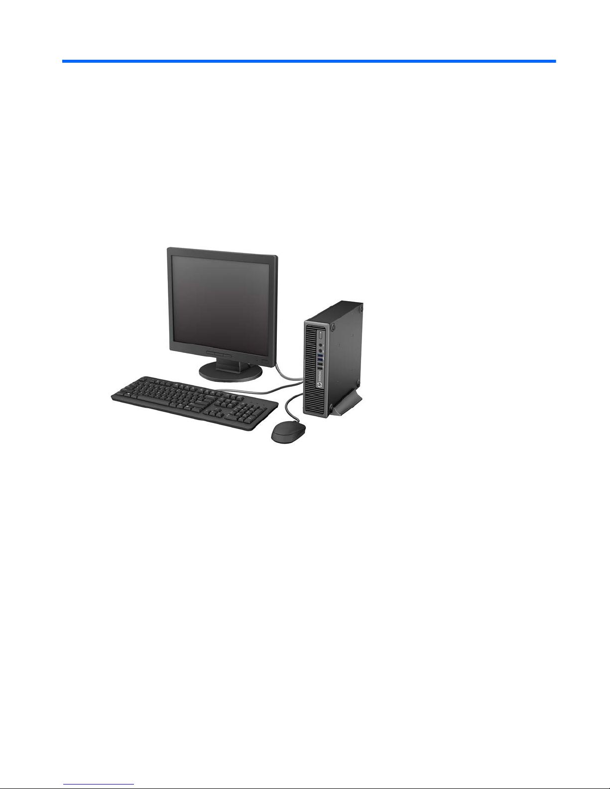
1 Product features
Standard configuration features
Standard configuration features
1
Page 10
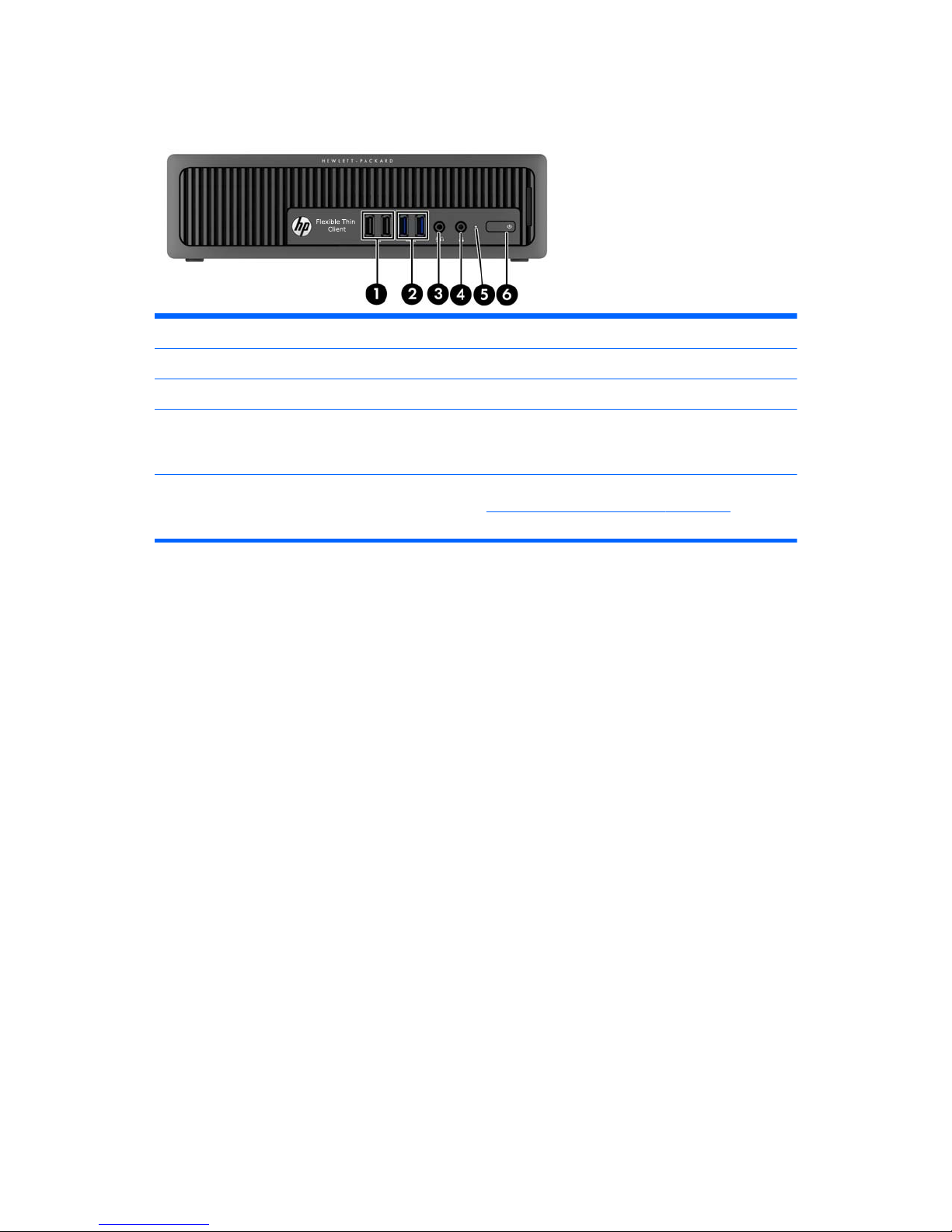
Front panel components
1 USB 2.0 Ports (black) 4 Headphone Connector
2 USB 3.0 Ports (blue) 5 Hard Drive Activity Light
3 Microphone/Headphone Connector 6 Dual-State Power Button
NOTE: When a device is plugged into the Microphone/Headphone Connector, a dialog box appears asking if
you want to use the connector for a microphone Line-In device or a headphone. You can reconfigure the connector
at any time by double-clicking the Audio Manager icon in the Windows
®
taskbar.
NOTE: The Power On Light is normally white when the power is on. If it is flashing red, there is a problem with the
computer and it is displaying a diagnostic code. Refer to the
Diagnostics and Troubleshooting on page 71 to
interpret the code.
2 Chapter 1 Product features
Page 11

Rear panel components
1 Line-Out Connector for powered audio devices
(green)
7 Power Cord Connector
2
USB 2.0 Ports (black) 8 Line-In Audio Connector (blue)
3
USB 3.0 Ports (blue) 9 RJ-45 Network Connector
4
Dual-Mode DisplayPort Monitor Connectors 10 PS/2 Mouse Connector (green)
5
PS/2 Keyboard Connector (purple) 11 Fiber NIC (optional)
6
VGA Monitor Connector
NOTE: When a device is plugged into the blue Line-In Audio Connector, a dialog box will pop up asking if you
want to use the connector for a line-in device or a microphone. You can reconfigure the connector at any time by
double-clicking the Audio Manager icon in the Windows taskbar.
If an MXM graphics card is installed, all of the video connectors may be used at the same time. However, for such a
configuration, only the display connected to the upper DisplayPort will display POST messages.
The system board graphics can be disabled by changing settings in Computer Setup.
Rear panel components
3
Page 12
Serial number location
Each computer has a unique serial number and a product ID number that are located on the exterior of
the computer. Keep these numbers available for use when contacting customer service for assistance.
4 Chapter 1 Product features
Page 13
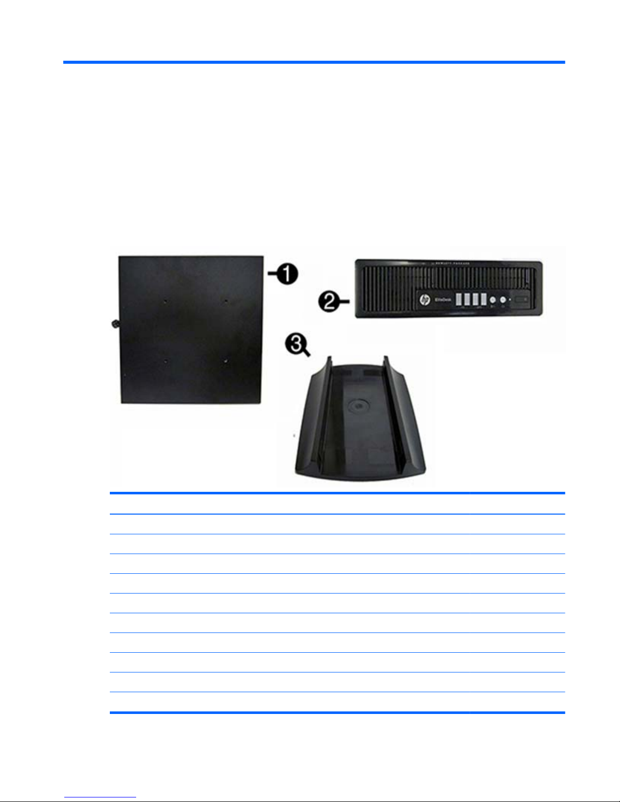
2 Illustrated parts catalog
Computer major components
Item Description Spare part number
(1) Access panel 732763-001
(2) Front bezel 732764-001
(3) Stand 612496-001
System board (includes replacement thermal material)
For use in models with WES7 737729-001
AC adapter
180W, standard 613766-001
135W, standard 648964-001
Memory modules (PC3-12800)
8-GB 689374-001
Computer major components
5
Page 14

Item Description Spare part number
4-GB 689373-001
2-GB 689372-001
Processors (include replacement thermal material)
Intel Pentium G3220 (3.0-GHz, 3-MB L3 cache, 54W) 742564-001
Intel Core i5 4570s (2.9-GHz, 6-MB L3 cache, 65W) 732505-001
Drives
Description Spare part number
mSATA drive
32-GB 719566-001
16-GB 719565-001
Misc boards
Description Spare part number
AMD Radeon HD 7650A 2GB MXM Graphics 708866-001
HP WLAN 802.11 a/b/g/n 2x2 PCIe NIC 695915-001
6 Chapter 2 Illustrated parts catalog
Page 15
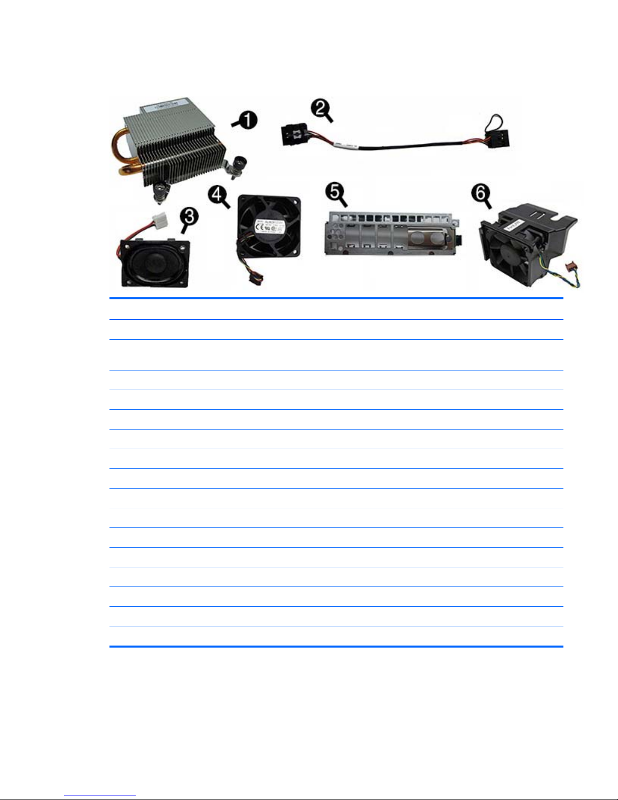
Misc parts
Item Description Spare part number
(1) Heat sink for use with the processor (includes replacement thermal material) 587456-001
Heat sink for use with the discrete graphics card (includes replacement thermal
material; not illustrated)
689369-001
(2) Power switch assembly 732767-001
(3) Speaker 689384-001
(4) Fan, rear 691352-001
(5) Front I/O panel 732762-001
(6) Chassis fan, front 732765-001
SATA data cable, 25.2-inch 638814-001
Solenoid lock 732772-001
Drive cage 732761-001
Mouse
PS2, optical 674315-001
USB, optical 674316-001
Keyboard
USB 724724-xx1
PS/2 701423-xx1
Misc parts
7
Page 16

Sequential part number listing
Spare part
number
Description
587456-001 Heat sink for use with the processor (includes thermal material)
612496-001 Stand
613766-001 180-W power adapter, standard
638814-001 SATA data cable, 25.2-inch
638816-001 Hood sensor
648964-001 AC adapter, 135W, standard
674315-001 Mouse, PS2, optical
674316-001 Mouse, USB, optical
689369-001 Heat sink for use on models with discrete graphics cards (includes thermal material)
689372-001 Memory module, 2-GB, PC3-12800
689373-001 Memory module, 4-GB, PC3-12800
689374-001 Memory module, 8-GB, PC3-12800
689384-001 Speaker
691352-001 Chassis fan, rear
695915-001 HP WLAN 802.11 a/b/g/n 2x2 PCIe NIC
701423-xx1 Keyboard, PS/2
701424-xx1 Keyboard, USB
708866-001 AMD Radeon HD 7650A 2GB MXM Graphics
719565-001 16-GB mSATA drive
719566-001 32-GB mSATA drive
729624-001 Fiber NIC assembly, AT-2711FXa, PCIe
732505-001 Intel Core i5 4570s (2.9-GHz, 6-MB L3 cache, 65W)
732761-001 Drive cage
732762-001 Front I/O assembly
732763-001 Access panel
732764-001 Front bezel
732765-001 Front fan
732767-001 Power switch assembly
732772-001 Solenoid lock
8 Chapter 2 Illustrated parts catalog
Page 17

Spare part
number
Description
737729-001 System board for use in models with WES7 (includes replacement thermal material)
742564-001 Intel Pentium G3220 processor (3.0-GHz, 3-MB L3 cache, 54W)
Sequential part number listing
9
Page 18

3 Routine care and disassembly
preparation
This chapter provides general service information for the computer. Adherence to the procedures and
precautions described in this chapter is essential for proper service.
CAUTION: When the computer is plugged into an AC power source, voltage is always applied to
the system board. You must disconnect the power cord from the power source before opening the
computer to prevent system board or component damage.
Electrostatic discharge information
A sudden discharge of static electricity from your finger or other conductor can destroy static-sensitive
devices or microcircuitry. Often the spark is neither felt nor heard, but damage occurs. An electronic
device exposed to electrostatic discharge (ESD) may not appear to be affected at all and can work
perfectly throughout a normal cycle. The device may function normally for a while, but it has been
degraded in the internal layers, reducing its life expectancy.
Networks built into many integrated circuits provide some protection, but in many cases, the discharge
contains enough power to alter device parameters or melt silicon junctions.
10 Chapter 3 Routine care and disassembly preparation
Page 19

Generating static
The following table shows that:
●
Different activities generate different amounts of static electricity.
●
Static electricity increases as humidity decreases.
Relative Humidity
Event 55% 40% 10%
Walking across carpet
Walking across vinyl floor
Motions of bench worker
Removing DIPs from plastic tube
7,500 V
3,000 V
400 V
400 V
15,000 V
5,000 V
800 V
700 V
35,000 V
12,000 V
6,000 V
2,000 V
Removing DIPs from vinyl tray
Removing DIPs from Styrofoam
Removing bubble pack from PCB
Packing PCBs in foam-lined box
2,000 V
3,500 V
7,000 V
5,000 V
4,000 V
5,000 V
20,000 V
11,000 V
11,500 V
14,500 V
26,500 V
21,000 V
These are then multi-packaged inside plastic tubes, trays, or Styrofoam.
NOTE: 700 volts can degrade a product.
Preventing electrostatic damage to equipment
Many electronic components are sensitive to ESD. Circuitry design and structure determine the degree
of sensitivity. The following packaging and grounding precautions are necessary to prevent damage to
electric components and accessories.
●
To avoid hand contact, transport products in static-safe containers such as tubes, bags, or boxes.
●
Protect all electrostatic parts and assemblies with conductive or approved containers or
packaging.
●
Keep electrostatic sensitive parts in their containers until they arrive at static-free stations.
●
Place items on a grounded surface before removing them from their container.
●
Always be properly grounded when touching a sensitive component or assembly.
●
Avoid contact with pins, leads, or circuitry.
●
Place reusable electrostatic-sensitive parts from assemblies in protective packaging or conductive
foam.
Electrostatic discharge information
11
Page 20

Personal grounding methods and equipment
Use the following equipment to prevent static electricity damage to equipment:
●
Wrist straps are flexible straps with a maximum of one-megohm ± 10% resistance in the ground
cords. To provide proper ground, a strap must be worn snug against bare skin. The ground cord
must be connected and fit snugly into the banana plug connector on the grounding mat or
workstation.
●
Heel straps/Toe straps/Boot straps can be used at standing workstations and are
compatible with most types of shoes or boots. On conductive floors or dissipative floor mats, use
them on both feet with a maximum of one-megohm ± 10% resistance between the operator and
ground.
Static Shielding Protection Levels
Method Voltage
Antistatic plastic
Carbon-loaded plastic
Metallized laminate
1,500
7,500
15,000
Grounding the work area
To prevent static damage at the work area, use the following precautions:
●
Cover the work surface with approved static-dissipative material. Provide a wrist strap connected
to the work surface and properly grounded tools and equipment.
●
Use static-dissipative mats, foot straps, or air ionizers to give added protection.
●
Handle electrostatic sensitive components, parts, and assemblies by the case or PCB laminate.
Handle them only at static-free work areas.
●
Turn off power and input signals before inserting and removing connectors or test equipment.
●
Use fixtures made of static-safe materials when fixtures must directly contact dissipative surfaces.
●
Keep work area free of nonconductive materials such as ordinary plastic assembly aids and
Styrofoam.
●
Use field service tools, such as cutters, screwdrivers, and vacuums, that are conductive.
Recommended materials and equipment
Materials and equipment that are recommended for use in preventing static electricity include:
●
Antistatic tape
●
Antistatic smocks, aprons, or sleeve protectors
●
Conductive bins and other assembly or soldering aids
12 Chapter 3 Routine care and disassembly preparation
Page 21

●
Conductive foam
●
Conductive tabletop workstations with ground cord of one-megohm +/- 10% resistance
●
Static-dissipative table or floor mats with hard tie to ground
●
Field service kits
●
Static awareness labels
●
Wrist straps and footwear straps providing one-megohm +/- 10% resistance
●
Material handling packages
●
Conductive plastic bags
●
Conductive plastic tubes
●
Conductive tote boxes
●
Opaque shielding bags
●
Transparent metallized shielding bags
●
Transparent shielding tubes
Operating guidelines
To prevent overheating and to help prolong the life of the computer:
●
Keep the computer away from excessive moisture, direct sunlight, and extremes of heat and cold.
●
Operate the computer on a sturdy, level surface. Leave a 10.2-cm (4-inch) clearance on all vented
sides of the computer and above the monitor to permit the required airflow.
●
Never restrict the airflow into the computer by blocking any vents or air intakes. Do not place the
keyboard, with the keyboard feet down, directly against the front of the desktop unit as this also
restricts airflow.
●
Occasionally clean the air vents on all vented sides of the computer. Lint, dust, and other foreign
matter can block the vents and limit the airflow. Be sure to unplug the computer before cleaning
the air vents.
●
Never operate the computer with the cover or side panel removed.
●
Do not stack computers on top of each other or place computers so near each other that they are
subject to each other’s re-circulated or preheated air.
●
If the computer is to be operated within a separate enclosure, intake and exhaust ventilation must
be provided on the enclosure, and the same operating guidelines listed above will still apply.
●
Keep liquids away from the computer and keyboard.
Operating guidelines
13
Page 22

●
Never cover the ventilation slots on the monitor with any type of material.
●
Install or enable power management functions of the operating system or other software, including
sleep states.
Routine care
General cleaning safety precautions
1. Never use solvents or flammable solutions to clean the computer.
2. Never immerse any parts in water or cleaning solutions; apply any liquids to a clean cloth and
then use the cloth on the component.
3. Always unplug the computer when cleaning with liquids or damp cloths.
4. Always unplug the computer before cleaning the keyboard, mouse, or air vents.
5. Disconnect the keyboard before cleaning it.
6. Wear safety glasses equipped with side shields when cleaning the keyboard.
Cleaning the Computer Case
Follow all safety precautions in General cleaning safety precautions on page 14 before cleaning the
computer.
To clean the computer case, follow the procedures described below:
●
To remove light stains or dirt, use plain water with a clean, lint-free cloth or swab.
●
For stronger stains, use a mild dishwashing liquid diluted with water. Rinse well by wiping it with
a cloth or swab dampened with clear water.
●
For stubborn stains, use isopropyl (rubbing) alcohol. No rinsing is needed as the alcohol will
evaporate quickly and not leave a residue.
●
After cleaning, always wipe the unit with a clean, lint-free cloth.
●
Occasionally clean the air vents on the computer. Lint and other foreign matter can block the vents
and limit the airflow.
Cleaning the keyboard
Follow all safety precautions in General cleaning safety precautions on page 14 before cleaning the
keyboard.
To clean the tops of the keys or the keyboard body, follow the procedures described in
Cleaning the
Computer Case on page 14.
When cleaning debris from under the keys, review all rules in
General cleaning safety precautions
on page 14 before following these procedures:
14 Chapter 3 Routine care and disassembly preparation
Page 23

CAUTION: Use safety glasses equipped with side shields before attempting to clean debris from
under the keys.
●
Visible debris underneath or between the keys may be removed by vacuuming or shaking.
●
Canned, pressurized air may be used to clean debris from under the keys. Caution should be used
as too much air pressure can dislodge lubricants applied under the wide keys.
●
If you remove a key, use a specially designed key puller to prevent damage to the keys. This tool
is available through many electronic supply outlets.
CAUTION: Never remove a wide leveled key (like the space bar) from the keyboard. If these
keys are improperly removed or installed, the keyboard may not function properly.
●
Cleaning under a key may be done with a swab moistened with isopropyl alcohol and squeezed
out. Be careful not to wipe away lubricants necessary for proper key functions. Use tweezers to
remove any fibers or dirt in confined areas. Allow the parts to air dry before reassembly.
Cleaning the monitor
●
Wipe the monitor screen with a clean cloth moistened with water or with a towelette designed for
cleaning monitors. Do not use sprays or aerosols directly on the screen; the liquid may seep into
the housing and damage a component. Never use solvents or flammable liquids on the monitor.
●
To clean the monitor body follow the procedures in
Cleaning the Computer Case on page 14.
Cleaning the mouse
Before cleaning the mouse, ensure that the power to the computer is turned off.
●
Clean the mouse ball by first removing the retaining plate and the ball from the housing. Pull out
any debris from the ball socket and wipe the ball with a clean, dry cloth before reassembly.
●
To clean the mouse body, follow the procedures in
Cleaning the Computer Case on page 14.
Service considerations
Listed below are some of the considerations that you should keep in mind during the disassembly and
assembly of the computer.
Tools and software requirements
To service the computer, you need the following:
●
Torx T-15 screwdriver
●
Torx T-15 screwdriver with small diameter shank (for certain front bezel removal)
●
Flat-bladed screwdriver (may sometimes be used in place of the Torx screwdriver)
●
Phillips #2 screwdriver
Service considerations
15
Page 24

●
Diagnostics software
●
Tamper-resistant T-15 wrench
Screws
The screws used in the computer are not interchangeable. They may have standard or metric threads
and may be of different lengths. If an incorrect screw is used during the reassembly process, it can
damage the unit. HP strongly recommends that all screws removed during disassembly be kept with the
part that was removed, then returned to their proper locations.
CAUTION: Metric screws have a black finish. U.S. screws have a silver finish and are used on hard
drives only.
CAUTION: As each subassembly is removed from the computer, it should be placed away from the
work area to prevent damage.
Cables and connectors
Most cables used throughout the unit are flat, flexible cables. These cables must be handled with care
to avoid damage. Apply only the tension required to seat or unseat the cables during insertion or
removal from the connector. Handle cables by the connector whenever possible. In all cases, avoid
bending or twisting the cables, and ensure that the cables are routed in such a way that they cannot be
caught or snagged by parts being removed or replaced.
CAUTION: When servicing this computer, ensure that cables are placed in their proper location
during the reassembly process. Improper cable placement can damage the computer.
Lithium coin cell battery
The battery that comes with the computer provides power to the real-time clock and has a minimum
lifetime of about three years.
See the appropriate removal and replacement chapter for the chassis you are working on in this guide
for instructions on the replacement procedures.
WARNING! This computer contains a lithium battery. There is a risk of fire and chemical burn if the
battery is handled improperly. Do not disassemble, crush, puncture, short external contacts, dispose in
water or fire, or expose it to temperatures higher than 140ºF (60ºC). Do not attempt to recharge the
battery.
NOTE: Batteries, battery packs, and accumulators should not be disposed of together with the
general household waste. In order to forward them to recycling or proper disposal, please use the
public collection system or return them to HP, their authorized partners, or their agents.
16 Chapter 3 Routine care and disassembly preparation
Page 25

4 Removal and replacement
procedures
Adherence to the procedures and precautions described in this chapter is essential for proper service.
After completing all necessary removal and replacement procedures, run the Diagnostics utility to verify
that all components operate properly.
NOTE: Not all features listed in this guide are available on all computers.
Preparation for disassembly
See Routine care and disassembly preparation on page 10 for initial safety procedures.
1. Remove/disengage any security devices that prohibit opening the computer.
2. Remove all removable media, such as compact discs or USB flash drives, from the computer.
3. Turn off the computer properly through the operating system, then turn off any external devices.
4. Disconnect the power cord from the power outlet and disconnect any external devices.
CAUTION: Turn off the computer before disconnecting any cables.
Regardless of the power-on state, voltage is always present on the system board as long as the
system is plugged into an active AC outlet. In some systems the cooling fan is on even when the
computer is in the “Standby,” or “Suspend” modes. The power cord should always be
disconnected before servicing a unit.
5. If the computer is on a stand, remove the computer from the stand and lay the computer down.
NOTE: During disassembly, label each cable as you remove it, noting its position and routing.
Keep all screws with the units removed.
Preparation for disassembly
17
Page 26
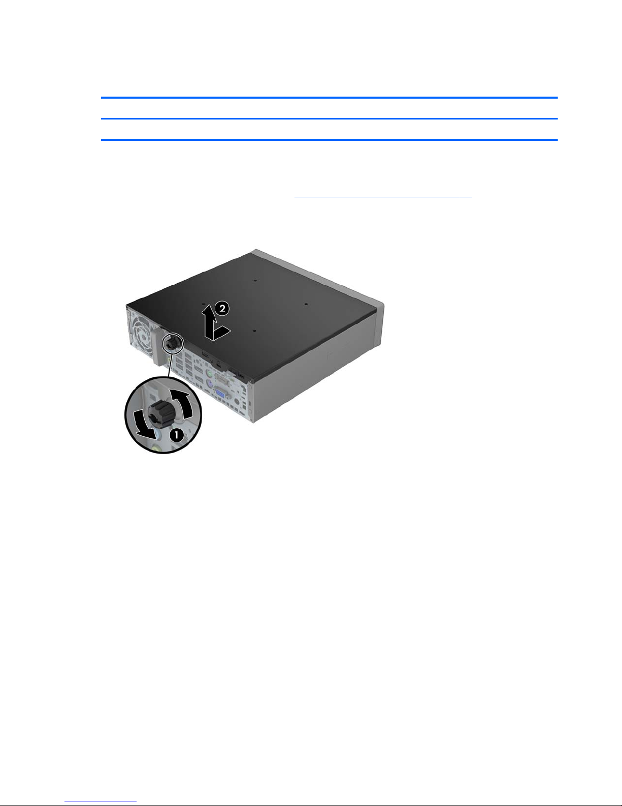
Access panel
Description Spare part number
Access panel 732763-001
To access internal components, you must remove the access panel:
1. Prepare the computer for disassembly (
Preparation for disassembly on page 17).
2. Loosen the thumbscrew on the rear of the computer (1), slide the access panel toward the rear of
the computer, then lift it off (2).
To install the access panel, reverse the removal procedure.
18 Chapter 4 Removal and replacement procedures
Page 27
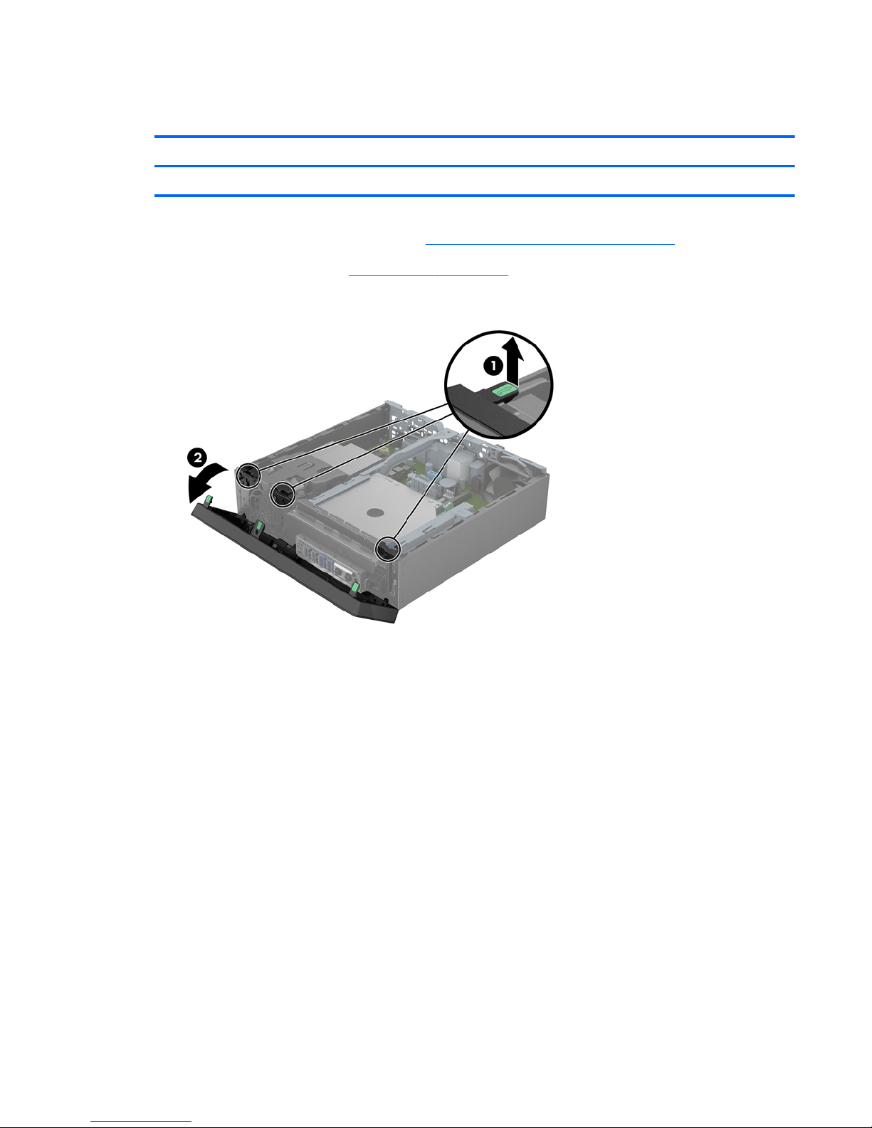
Front bezel
Description Spare part number
Front bezel 732764-001
1. Prepare the computer for disassembly (Preparation for disassembly on page 17).
2. Remove the access panel (
Access panel on page 18).
3. Lift up the three tabs on the side of the bezel (1), then rotate the bezel off the chassis (2).
To install the front bezel, reverse the removal procedure.
Front bezel
19
Page 28
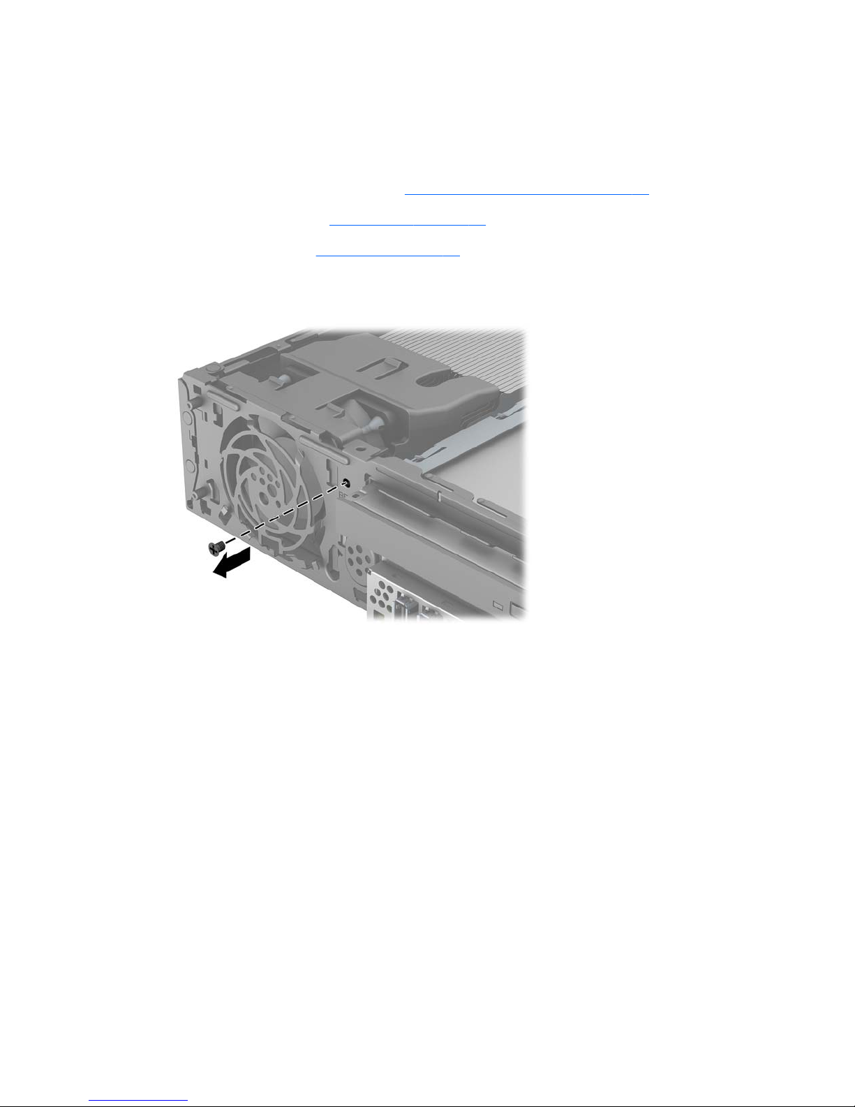
Front bezel security
The front bezel can be locked in place by installing a security screw provided by HP. To install the
security screw:
1. Prepare the computer for disassembly (
Preparation for disassembly on page 17).
2. Remove the access panel (
Access panel on page 18).
3. Remove the front bezel (
Front bezel on page 19).
4. Remove the black screw on the front of the chassis behind the bezel. The screw is labeled
"BEZEL."
5. Replace the front bezel.
20 Chapter 4 Removal and replacement procedures
Page 29
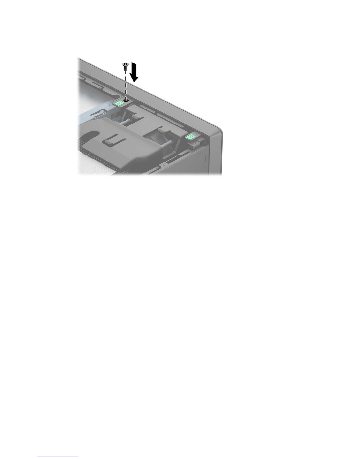
6. Install the security screw through the middle front bezel release tab and into the chassis to secure
the front bezel in place.
Front bezel security
21
Page 30

Memory
Description Spare part number
8-GB, PC3-12800, SODIMM 689374-001
4-GB, PC3-12800, SODIMM 689373-001
2-GB, PC3-12800, SODIMM 689372-001
The computer comes with double data rate 3 synchronous dynamic random access memory (DDR3SDRAM) small outline dual inline memory modules (SODIMMs).
SODIMMs
The memory sockets on the system board can be populated with up to two industry-standard
SODIMMs. These memory sockets are populated with at least one preinstalled SODIMM. To achieve
the maximum memory support, you can populate the system board with up to 16-GB of memory.
DDR3-SDRAM SODIMMs
For proper system operation, the SODIMMs must be:
●
industry-standard 204-pin
●
unbuffered non-ECC PC3-12800 DDR3-1600 MHz-compliant
●
1.35 volt or 1.5 volt DDR3-SDRAM SODIMMs
The DDR3-SDRAM SODIMMs must also:
●
support CAS latency 11 DDR3 1600 MHz (11-11-11 timing)
●
contain the mandatory Joint Electronic Device Engineering Council (JEDEC) specification
In addition, the computer supports:
●
512-Mbit, 1-Gbit, and 2-Gbit non-ECC memory technologies
●
single-sided and double-sided SODIMMS
●
SODIMMs constructed with x8 and x16 devices; SODIMMs constructed with x4 SDRAM are not
supported
NOTE: The system will not operate properly if you install unsupported SODIMMs.
22 Chapter 4 Removal and replacement procedures
Page 31

Populating SODIMM sockets
There are two SODIMM sockets on the system board, with one socket per channel. The sockets are
labeled DIMM1 and DIMM3. The DIMM1 socket operates in memory channel B. The DIMM3 socket
operates in memory channel A.
Item Description System Board Label Socket Color
1 SODIMM1 socket, Channel B DIMM1 Black
2 SODIMM3 socket, Channel A DIMM3 Black
The system will automatically operate in single channel mode, dual channel mode, or flex mode,
depending on how the SODIMMs are installed.
●
The system will operate in single channel mode if the SODIMM sockets are populated in one
channel only.
●
The system will operate in a higher-performing dual channel mode if the memory capacity of the
SODIMM in Channel A is equal to the memory capacity of the SODIMM in Channel B.
●
The system will operate in flex mode if the memory capacity of the SODIMM in Channel A is not
equal to the memory capacity of the SODIMM in Channel B. In flex mode, the channel populated
with the least amount of memory describes the total amount of memory assigned to dual channel
and the remainder is assigned to single channel. If one channel will have more memory than the
other, the larger amount should be assigned to channel A.
●
In any mode, the maximum operational speed is determined by the slowest SODIMM in the
system.
Memory
23
Page 32

Installing SODIMMs
CAUTION: You must disconnect the power cord and wait approximately 30 seconds for the power
to drain before adding or removing memory modules. Regardless of the power-on state, voltage is
always supplied to the memory modules as long as the computer is plugged into an active AC outlet.
Adding or removing memory modules while voltage is present may cause irreparable damage to the
memory modules or system board.
The memory module sockets have gold-plated metal contacts. When upgrading the memory, it is
important to use memory modules with gold-plated metal contacts to prevent corrosion and/or
oxidation resulting from having incompatible metals in contact with each other.
Static electricity can damage the electronic components of the computer or optional cards. Before
beginning these procedures, ensure that you are discharged of static electricity by briefly touching a
grounded metal object. For more information, refer to
Electrostatic discharge information on page 10.
When handling a memory module, be careful not to touch any of the contacts. Doing so may damage
the module.
1. Prepare the computer for disassembly (Preparation for disassembly on page 17).
2. Remove the access panel (
Access panel on page 18).
3. Locate the memory module sockets on the system board.
WARNING! To reduce risk of personal injury from hot surfaces, allow the internal system
components to cool before touching.
4. To remove a SODIMM, press outward on the two latches on each side of the SODIMM (1) then
pull the SODIMM out of the socket (2).
To install memory modules, reverse the removal procedure.
The computer automatically recognizes the additional memory when you turn on the computer.
24 Chapter 4 Removal and replacement procedures
Page 33

Front fan
Description Spare part number
Front fan 732765-001
The front fan sits against the front on the left side of the chassis.
1. Prepare the computer for disassembly (
Preparation for disassembly on page 17).
2. Remove the access panel (
Access panel on page 18).
3. Disconnect the fan control cable from the red system board connector labeled CHFAN (1).
4. Lift the fan straight up and out of the chassis (2).
To install the front fan, reverse the removal procedure.
Front fan
25
Page 34

Speaker
Description Spare part number
Speaker 689384-001
The speaker is secured to the front of the chassis between the fan and the I/O ports. Remove the screws
from the outside and then remove the speaker from the inside.
1. Prepare the computer for disassembly (
Preparation for disassembly on page 17).
2. Remove the access panel (
Access panel on page 18).
3. Remove the front bezel (
Front bezel on page 19).
4. Remove the front fan (
Front fan on page 25).
5. Disconnect the speaker cable from the white system board connector labeled SPKR.
6. On the outside of the chassis, remove the two Torx T8 screws that secure the speaker to the
chassis (1), and then from the inside of the chassis, slide the speaker up to remove it (2).
To install the speaker, reverse the removal procedure.
26 Chapter 4 Removal and replacement procedures
Page 35

Heat sink
Description Spare part number
Heat sink 587456-001
The heat sink is secured by four Torx screws. It does not have an attached fan.
1. Prepare the computer for disassembly (
Preparation for disassembly on page 17).
2. Remove the access panel (
Access panel on page 18).
3. Lift the front fan up and place it on top of the drive cage. You do not need to disconnect the fan
cable from the system board.
4. Loosen the four Torx T15 screws that secure the heat sink to the system board, and then lift the
heat sink from the system board.
CAUTION: Heat sink retaining screws should be removed in diagonally opposite pairs (as in an
X) to even the downward forces on the processor to avoid damage that could require replacing
the system board.
5. Lay the heat sink on its top in a safe area to prevent the thermal grease from contaminating the
work surface.
If reusing the existing heat sink go to step 1.
Heat sink
27
Page 36

If using a new heat sink, go to step 3.
1. If reusing the existing heat sink, clean bottom of the heat sink and apply the thermal material
provided in the spares kit to the top of the processor.
2. Position the heat sink atop the processor.
3. If using a new heat sink, remove the protective covering from the bottom of the heat sink and
place it in position atop the processor.
4. Secure the heat sink to the system board with the 4 captive screws.
CAUTION: Heat sink retaining screws should be tightened in diagonally opposite pairs (as in
an X) to evenly seat the heat sink on the processor. This is especially important as the pins on the
socket are very fragile and any damage to them may require replacing the system board.
28 Chapter 4 Removal and replacement procedures
Page 37

Processor
Description Spare part number
Intel Pentium G3220 (3.0-GHz, 3-MB L3 cache, 54W) 742564-001
Intel Core i5 4570s (2.9-GHz, 6-MB L3 cache, 65W) 732505-001
1. Prepare the computer for disassembly (Preparation for disassembly on page 17).
2. Remove the access panel (
Access panel on page 18).
3. Remove the front bezel (
Front bezel on page 19).
4. Remove the heat sink (
Heat sink on page 27).
5. Rotate the processor locking lever to its full open position (1).
6. Raise and rotate the microprocessor retainer to its fully open position (2).
7. Carefully lift the processor from the socket (3).
CAUTION: Do NOT handle the pins in the processor socket. These pins are very fragile and
handling them could cause irreparable damage. Once pins are damaged it may be necessary to
replace the system board.
To install the processor, reverse the removal procedures.
NOTE: After installing a new processor onto the system board, always update the system ROM to
ensure that the latest version of the BIOS is being used on the computer. The latest system BIOS can be
found on the Web at:
http://www8.hp.com/us/en/support-drivers.html.
Processor
29
Page 38

Smart Cover Lock (solenoid lock)
Description Spare part number
Solenoid lock 732772-001
NOTE: The Smart Cover Lock is an optional feature included on some models only.
The Smart Cover Lock is a software-controllable cover lock, controlled by the setup password. This lock
prevents unauthorized access to the internal components. The computer ships with the Smart Cover Lock
in the unlocked position.
If you enable the Smart Cover Lock and cannot enter your password to disable the lock, you will need
a Smart Cover FailSafe Key to open the computer cover. You will need the key to access the internal
computer components in any of the following circumstances:
●
Power outage
●
Startup failure
●
PC component (for example, processor or power supply) failure
●
Forgotten password
NOTE: The Smart Cover FailSafe Key is a specialized tool available from HP. Be prepared; order this
key before you need it.
To obtain a FailSafe Key:
●
Contact an authorized HP reseller or service provider. Order PN 166527-001 for the wrench-style
key or PN 166527-002 for the screwdriver bit key.
●
Refer to the HP Web site (
http://www.hp.com) for ordering information.
●
Call the appropriate number listed in the warranty.
The solenoid lock is mounted to the back of the computer. Remove it using one security screw on the
outside of the computer.
1. Prepare the computer for disassembly (
Preparation for disassembly on page 17).
2. Remove the access panel (
Access panel on page 18).
30 Chapter 4 Removal and replacement procedures
Page 39

3. From the outside, rear side of the chassis, remove the silver security screw that secures the lock to
the chassis.
4. From the inside of the chassis, lift the lock up to gain access to the system board connector.
Smart Cover Lock (solenoid lock)
31
Page 40

5. Disconnect the cable from the system board connector labeled HLOCK.
To install the Smart Cover Lock, reverse the removal procedure.
Refer to the following image for the location of the slots on the back of the chassis in which to install the
lock. When installing, insert the top tabs into the top slots, and then rotate the lock downward. Then
install the security screw on the outside of the computer. Plug the connector into the system board
connector.
32 Chapter 4 Removal and replacement procedures
Page 41

Smart Cover Lock (solenoid lock)
33
Page 42

Drive cage (fiber NIC assembly holder)
Description Spare part number
Drive cage 732761-001
The drive cage sits behind the USB ports on the front of the chassis.
On this thin client, the drive cage does not support drives. The only component the drive cage houses is
the fiber NIC assembly.
1. Prepare the computer for disassembly (
Preparation for disassembly on page 17).
2. Remove the access panel (
Access panel on page 18).
3. Remove the two Torx screws that secure cage to the chassis (1), lift the tab (2) on the cage, slide
the cage toward the rear of the unit (3), and then pull the cage up and out of the chassis.
To install the drive cage, reverse the removal procedures.
34 Chapter 4 Removal and replacement procedures
Page 43

mSATA drive
Description Spare part number
32-GB mSATA drive 719566-001
16-GB mSATA drive 719565-001
The mSATA drive is installed onto the system board underneath the hard drive cage.
Remove the mSATA drive:
1. Prepare the computer for disassembly (
Preparation for disassembly on page 17).
2. Remove the access panel (
Access panel on page 18).
3. Remove the drive cage (
Drive cage (fiber NIC assembly holder) on page 34).
4. Remove the two Phillips screws (1) that secure the drive to the computer.
5. Slide the drive away to remove it from the socket (2).
Reverse this procedure to install the mSATA drive.
mSATA drive
35
Page 44

Hood sensor
Description Spare part number
Hood sensor 638816-001
1. Prepare the computer for disassembly (Preparation for disassembly on page 17).
2. Remove the access panel (
Access panel on page 18).
3. Remove the drive cage (
Drive cage (fiber NIC assembly holder) on page 34).
4. Unplug the hood sensor cable from the white system board connector labeled HSENSE (1) and
remove the cable from the white clip mounted on the inside chassis wall (2).
5. Slide the hood sensor into the chassis to remove it from its slot (3). Disengaging the hood sensor
from the chassis may require use of a screwdriver or similar tool.
To install the hood sensor, reverse the removal procedures.
36 Chapter 4 Removal and replacement procedures
Page 45

Installing the fiber NIC assembly
Description Spare part number
Fiber NIC assembly 729624-001
1. Prepare the computer for disassembly (Preparation for disassembly on page 17).
2. Remove the access panel (
Access panel on page 18).
3. Remove the drive cage (
Drive cage (fiber NIC assembly holder) on page 34).
4. Insert the Fiber NIC assembly into the hard drive carrier.
5. Insert the four Torx isolation screws to secure the assembly into the carrier.
Installing the fiber NIC assembly
37
Page 46

6. Insert the smaller fiber card into the PCI slot in the system board (1), and rotate the board
downward.
7. Insert the two Torx screws that secure the card onto the system board (1), and the insert the FFC
cable into the connector on the card.
8. Install the hard drive carrier assembly into the hard drive cage. For more information, see Drive
cage (fiber NIC assembly holder) on page 34.
38 Chapter 4 Removal and replacement procedures
Page 47

9. Route the cable through the front of the hard drive carrier cage, and then insert the cable into the
connector on the larger fiber card..
10. Install the clips in the two locations as shown in the following image, and then route the cables
through the clips.
Installing the fiber NIC assembly
39
Page 48

11. Disconnect the cable ends from the connector.
12. On the outside, rear of the computer, install the connector by inserting the connector through the
slot on the computer, and then inserting the two Torx screws to secure the connector.
13. From the inside, rear of the computer, plug the cables into the connector. Plug the white cable into
the port labeled ‘R’ and the green cable into the port labeled ‘T’.
To remove the fiber NIC assembly, reverse the removal procedures.
40 Chapter 4 Removal and replacement procedures
Page 49

WLAN module
Description Spare part number
HP WLAN 802.11 a/b/g/n 2x2 PCIe NIC 695915-001
1. Prepare the computer for disassembly (Preparation for disassembly on page 17).
2. Remove the access panel (
Access panel on page 18).
3. Remove the drive cage (
Drive cage (fiber NIC assembly holder) on page 34).
4. Disconnect the two antenna cables from the connectors on the module (1).
5. Remove the two Phillips screws (2) that secure the module to the system board.
6. Lift the module to a 45 degree angle, and then remove the module from the connector by pulling it
away at an angle (3).
To install the WLAN module, reverse the removal procedure. Make sure the antenna cables are
correctly routed.
WLAN module
41
Page 50

Graphics board
Description Spare part number
AMD Radeon HD 7650A 2GB MXM Graphics 708866-001
CAUTION: Be very careful when removing or replacing the system board to prevent damaging it.
1. Prepare the computer for disassembly (Preparation for disassembly on page 17).
2. Remove the access panel (
Access panel on page 18).
3. Remove the drive cage (
Drive cage (fiber NIC assembly holder) on page 34).
4. Remove the two Torx T8 screws (1) that secure the graphics board to the system board, rotate the
board upward to a 45-degree angle (2), and the pull it away from the system board connector
and out of the computer (3).
NOTE: Graphics card appearance may vary.
To install the graphics board, reverse the removal procedure.
If you need to remove the heat sink from the graphics board, loosen the four captive Torx screws that
secure the heat sink from the graphics board, and then lift the heat sink from the graphics board.
42 Chapter 4 Removal and replacement procedures
Page 51

Power switch
Description Spare part number
Power switch 732767-001
1. Prepare the computer for disassembly (Preparation for disassembly on page 17).
2. Remove the access panel (
Access panel on page 18).
3. Remove the front bezel (
Front bezel on page 19).
4. Remove the drive cage (
Drive cage (fiber NIC assembly holder) on page 34).
5. Disconnect the power switch cable from the system board connector labeled PB/LED.
6. Remove the power switch cable from atop the front I/O bracket.
7. From the front of the computer, press down (or squeeze) on the top on the power switch (1), and
then rotate it down (2) to disengage it from the chassis.
8. Pull the power switch and cable assembly out through the hole in the front of the chassis.
To install the power switch, reverse the removal procedure.
Power switch
43
Page 52

System board
Description Spare part number
System board for use in models with WES7 737729-001
Front I/O panel 732762-001
CAUTION: Be very careful when removing or replacing the system board to prevent damaging it.
When replacing the system board, make sure to remove the following components (as applicable) from
the old system board and install them on the new system board:
●
Memory modules (
Memory on page 22).
●
mSATA drive (
mSATA drive on page 35).
●
Processor (
Processor on page 29).
●
WLAN module (
WLAN module on page 41).
●
Graphics board (
Graphics board on page 42).
1. Prepare the computer for disassembly (
Preparation for disassembly on page 17).
2. Remove the access panel (
Access panel on page 18).
3. Remove the front fan (
Front fan on page 25).
4. Remove the drive cage (
Drive cage (fiber NIC assembly holder) on page 34).
5. Remove the fiber NIC assembly (
Installing the fiber NIC assembly on page 37).
6. Remove the heat sink (
Heat sink on page 27).
7. Disconnect the rear fan cable from the system board.
8. Remove the power button cable from atop the front I/O panel.
9. Disconnect any remaining cables connected to the system board, noting their location for
reinstallation.
44 Chapter 4 Removal and replacement procedures
Page 53

10. Remove the front I/O panel:
a. Remove the Torx T15 screw from the right side of the panel that secures it to the front of the
chassis.
b. Press the tab on right side of the panel (1), and then swing the right side of the cage away
from the chassis to remove it (2).
System board
45
Page 54

11. Remove the three remaining Torx T15 screws that secure the system board to the chassis.
12. Slide system board toward the front of the unit until the rear connectors are clear of their slots in
the chassis (1).
13. Lift the rear of the system board until it clears the chassis, and then remove the system board from
the chassis (2).
To install the system board, reverse the removal procedure.
NOTE: When replacing the system board, you must also change the chassis serial number in the
BIOS.
46 Chapter 4 Removal and replacement procedures
Page 55

Rear fan
Description Spare part number
Rear fan 691352-001
The rear fan is secured to the rear right corner of the chassis. You must remove the system board before
you can remove the rear fan.
1. Prepare the computer for disassembly (
Preparation for disassembly on page 17).
2. Remove the access panel (
Access panel on page 18).
3. Remove the front fan (
Front fan on page 25).
4. Remove the drive cage (
Drive cage (fiber NIC assembly holder) on page 34).
5. Remove the fiber NIC assembly (
Installing the fiber NIC assembly on page 37).
6. Remove the heat sink (
Heat sink on page 27).
7. Remove the system board (
System board on page 44).
8. From the outside of the chassis, remove the four Phillips screws that secure the fan to the chassis.
Rear fan
47
Page 56

9. From the inside of the chassis, slide the fan out from underneath the chassis lip, and then remove
the fan.
To install the rear fan, reverse the removal procedure.
48 Chapter 4 Removal and replacement procedures
Page 57

Antennas
Two antennas are secured to chassis – one on the front, one on the back. You must remove all other
components to remove the antennas.
1. Prepare the computer for disassembly (
Preparation for disassembly on page 17).
2. Remove the access panel (
Access panel on page 18).
3. Remove the front fan (
Front fan on page 25).
4. Remove the drive cage (
Drive cage (fiber NIC assembly holder) on page 34).
5. Remove the fiber NIC assembly (
Installing the fiber NIC assembly on page 37).
6. Remove the heat sink (
Heat sink on page 27).
7. Remove the system board (
System board on page 44).
8. Remove the rear fan (
Rear fan on page 47).
9. To remove the front antenna, from the inside of the front of the chassis, remove the antenna from
the clips built into the base pan.
10. From the outside of the front of the chassis, remove the two Torx T8 screws (1) that secure the
antenna to the chassis.
Antennas
49
Page 58

11. Pull the antenna out of the clips on the front of the chassis (2), and then pull the antenna out of the
hole it routes through (3).
12. To remove the rear antenna, from the inside of the front of the chassis, remove the antenna from
the plastic clips attached to the side of the chassis.
50 Chapter 4 Removal and replacement procedures
Page 59

13. From the outside of the rear of the chassis, remove the two Torx T8 screws that secure the antenna
to the chassis.
14. Pull the antenna through the hole it routes through.
To install the rear fan, reverse the removal procedure.
Antennas
51
Page 60

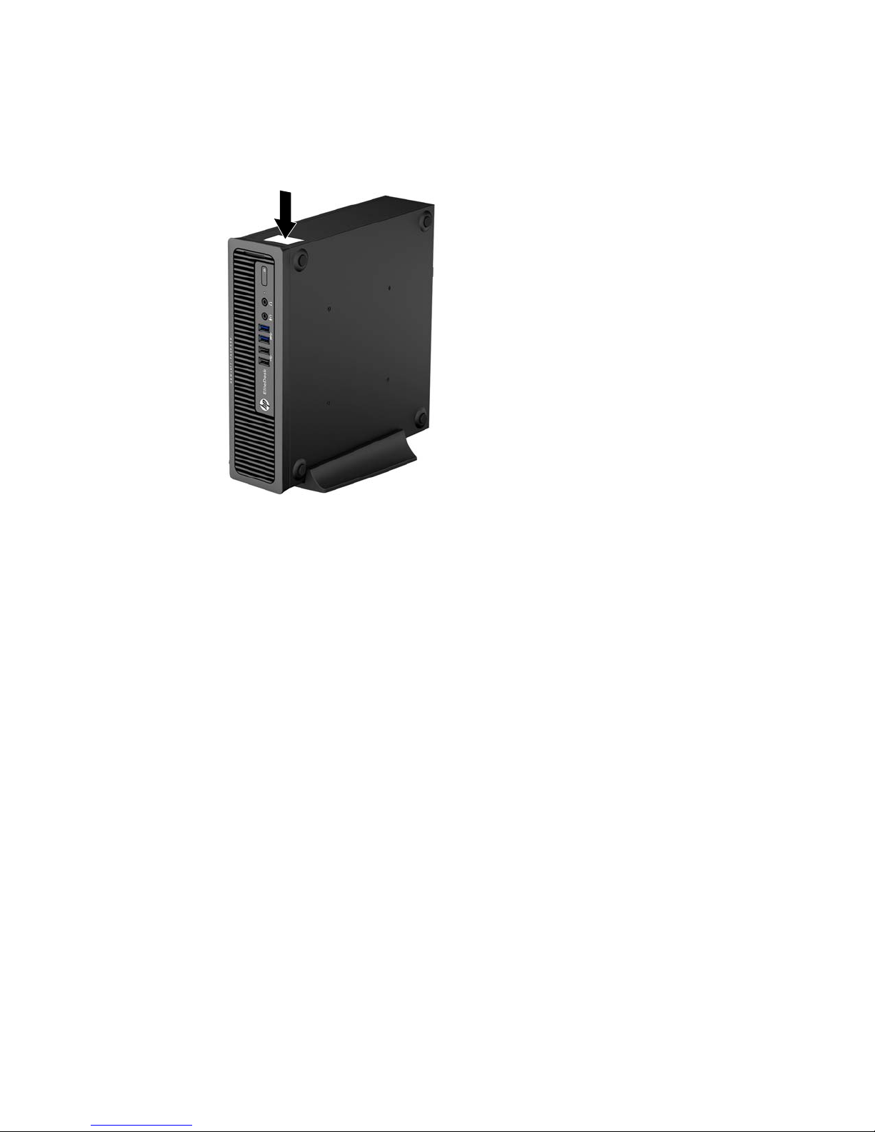
Changing from desktop to tower configuration
The computer can be used in a tower orientation with the tower stand included with the computer.
1. Remove/disengage any security devices that prohibit opening the computer.
2. Remove all removable media, such as compact discs or USB flash drives, from the computer.
3. Turn off the computer properly through the operating system, then turn off any external devices.
4. Disconnect the power cord from the power outlet and disconnect any external devices.
CAUTION: Regardless of the power-on state, voltage is always present on the system board as
long as the system is plugged into an active AC outlet. You must disconnect the power cord to
avoid damage to the internal components of the computer.
5. Orient the computer so that its left side is facing down, and place the computer firmly down into
the stand.
6. Reconnect the external equipment, plug the power cord into a power outlet, and turn the computer
on.
NOTE: Ensure at least 10.2 centimeters (4 inches) of space on all sides of the computer remains
clear and free of obstructions.
NOTE: An optional Quick Release mounting bracket is available from HP for mounting the computer
to a wall, desk, or swing arm. When the mounting bracket is used, do not install the computer with the
I/O ports oriented towards the ground.
52 Chapter 4 Removal and replacement procedures
Page 61

Port cover
An optional rear port cover is available for the computer.
To install the port cover:
1. Thread the cables through the bottom hole on the port cover (1) and connect the cables to the rear
ports on the computer.
2. Insert the hooks on the port cover into the slots on the rear of the chassis, then slide the cover to
the right to secure it in place (2).
NOTE: For security purposes, you can install an optional cable lock to the chassis that locks the port
cover and secures the computer.
The port cover is secured in place by a retention lever just inside the port cover opening. To remove the
port cover, pull the lever back towards the port cover opening (1), then slide the cover to the left and
off the computer (2).
Port cover
53
Page 62

Power supply, external
The chassis uses an external power supply.
WARNING! To reduce potential safety issues, only the power supply provided with the computer, a
replacement power supply provided by HP, or a power supply purchased as an accessory from HP
should be used with the computer.
54 Chapter 4 Removal and replacement procedures
Page 63

A Battery replacement
The battery that comes with the computer provides power to the real-time clock. When replacing the
battery, use a battery equivalent to the battery originally installed in the computer. The computer comes
with a 3-volt lithium coin cell battery.
WARNING! The computer contains an internal lithium manganese dioxide battery. There is a risk of
fire and burns if the battery is not handled properly. To reduce the risk of personal injury:
Do not attempt to recharge the battery.
Do not expose to temperatures higher than 60°C (140ºF).
Do not disassemble, crush, puncture, short external contacts, or dispose of in fire or water.
Replace the battery only with the HP spare designated for this product.
CAUTION: Before replacing the battery, it is important to back up the computer CMOS settings.
When the battery is removed or replaced, the CMOS settings will be cleared.
Static electricity can damage the electronic components of the computer or optional equipment. Before
beginning these procedures, ensure that you are discharged of static electricity by briefly touching a
grounded metal object.
NOTE: The lifetime of the lithium battery can be extended by plugging the computer into a live AC
wall socket. The lithium battery is only used when the computer is NOT connected to AC power.
HP encourages customers to recycle used electronic hardware, HP original print cartridges, and
rechargeable batteries. For more information about recycling programs, go to
http://www.hp.com/
recycle.
1. Remove/disengage any security devices that prohibit opening the computer.
2. Remove all removable media, such as compact discs or USB flash drives, from the computer.
3. Turn off the computer properly through the operating system, then turn off any external devices.
4. Disconnect the power cord from the power outlet and disconnect any external devices.
CAUTION: Regardless of the power-on state, voltage is always present on the system board as
long as the system is plugged into an active AC outlet. You must disconnect the power cord to
avoid damage to the internal components of the computer.
5. Remove the access panel.
55
Page 64

6. Locate the battery and battery holder on the system board.
NOTE: On some computer models, it may be necessary to remove an internal component to
gain access to the battery.
7. Depending on the type of battery holder on the system board, complete the following instructions
to replace the battery.
Type 1
a. Lift the battery out of its holder.
b. Slide the replacement battery into position, positive side up. The battery holder automatically
secures the battery in the proper position.
Type 2
a. To release the battery from its holder, squeeze the metal clamp that extends above one edge
of the battery. When the battery pops up, lift it out (1).
b. To insert the new battery, slide one edge of the replacement battery under the holder’s lip
with the positive side up. Push the other edge down until the clamp snaps over the other edge
of the battery (2).
Type 3
a. Pull back on the clip (1) that is holding the battery in place, and remove the battery (2).
56 Appendix A Battery replacement
Page 65

b. Insert the new battery and position the clip back into place.
NOTE: After the battery has been replaced, use the following steps to complete this procedure.
8. Replace the access panel.
9. Plug in the computer and turn on power to the computer.
10. Reset the date and time, your passwords, and any special system setups using Computer Setup.
11. Lock any security devices that were disengaged when the access panel was removed.
57
Page 66

B Computer Setup (F10) Utility, BIOS
Settings
Computer Setup (F10) Utilities
Use Computer Setup (F10) Utility to do the following:
●
Change factory default settings.
●
Set the system date and time.
●
Set, view, change, or verify the system configuration, including settings for processor, graphics,
memory, audio, storage, communications, and input devices.
●
Modify the boot order of bootable devices such as solid-state drives or USB flash media devices.
●
Select Post Messages Enabled or Disabled to change the display status of Power-On Self-Test
(POST) messages. Post Messages Disabled suppresses most POST messages, such as memory
count, product name, and other non-error text messages. If a POST error occurs, the error is
displayed regardless of the mode selected. To manually switch to Post Messages Enabled during
POST, press any key (except F1 through F12).
●
Establish an Ownership Tag, the text of which is displayed each time the system is turned on or
restarted.
●
Enter the Asset Tag or property identification number assigned by the company to this computer.
●
Enable the power-on password prompt during system restarts (warm boots) as well as during
power-on.
●
Establish a setup password that controls access to the Computer Setup (F10) Utility and the settings
described in this section.
●
Secure integrated I/O functionality, including the USB, audio, or embedded NIC, so that they
cannot be used until they are unsecured.
●
Enable or disable removable media boot ability.
●
Replicate the system setup by saving system configuration information on a USB device and
restoring it on one or more computers.
●
Enable or disable DriveLock security (when supported by drive).
58 Appendix B Computer Setup (F10) Utility, BIOS Settings
Page 67

Using Computer Setup (F10) Utilities
Computer Setup can be accessed only by turning the computer on or restarting the system. To access
the Computer Setup Utilities menu, complete the following steps:
1. Turn on or restart the computer.
2. Press either Esc or F10 while the “Press the ESC key for Startup Menu” message is displayed at the
bottom of the screen.
Pressing Esc displays a menu that allows you to access different options available at startup.
NOTE: If you do not press Esc or F10 at the appropriate time, you must restart the computer and
again press Esc or F10 when the monitor light turns green to access the utility.
NOTE: You can select the language for most menus, settings, and messages using the Language
Selection option in the ESC (Startup) Menu or using the F8 key in Computer Setup.
3. If you pressed Esc, press F10 to enter Computer Setup.
4. A choice of five headings appears in the Computer Setup Utilities menu: File, Storage, Security,
Power, and Advanced.
5. Use the arrow (left and right) keys to select the appropriate heading. Use the arrow (up and down)
keys to select the option you want, then press Enter. To return to the Computer Setup Utilities
menu, press Esc.
6. To apply and save changes, select File > Save Changes and Exit.
●
If you have made changes that you do not want applied, select Ignore Changes and
Exit.
●
To reset to factory settings or previously saved default settings (some models), select Apply
Defaults and Exit. This option will restore the original factory system defaults.
CAUTION: Do NOT turn the computer power OFF while the BIOS is saving the Computer Setup
(F10) changes because the CMOS could become corrupted. It is safe to turn off the computer only after
exiting the F10 Setup screen.
Table B-1 Computer Setup (F10) Utility
Heading Table
File
Computer Setup—File on page 60
Storage
Computer Setup—Storage on page 61
Security
Computer Setup—Security on page 62
Power
Computer Setup—Power on page 65
Advanced
Computer Setup—Advanced on page 66
Computer Setup (F10) Utilities
59
Page 68

Computer Setup—File
NOTE: Support for specific Computer Setup options may vary depending on the hardware
configuration.
Table B-2 Computer Setup—File
Option Description
System Information Lists:
●
Product name
●
SKU number (some models)
●
Processor type/speed/stepping
●
Cache size (L1/L2)
●
Installed memory size/speed, number of channels (single or dual) (if applicable)
●
Integrated MAC address for embedded, enabled NIC (if applicable)
●
System BIOS (includes family name and version)
●
Chassis serial number
●
Asset tracking number
About Displays copyright notice.
Set Time and Date Allows you to set system time and date.
Flash System ROM Allows you to update the system ROM with a BIOS image file located on removable media.
Replicated Setup Save to Removable Media
Saves system configuration to a formatted USB flash media device.
Restore from Removable Media
Restores system configuration from a USB flash media device.
Default Setup Save Current Settings as Default
Saves the current system configuration settings as the default to be used whenever “Apply Defaults
and Exit” is selected.
Restore Factory Settings as Default
Loads the original factory system configuration settings for use by a subsequent “Apply Defaults and
Exit” action.
Apply Defaults and
Exit
Applies the currently selected default settings.
Ignore Changes
and Exit
Exits Computer Setup without applying or saving any changes.
Save Changes and
Exit
Saves changes to system configuration or default settings and exits Computer Setup.
60 Appendix B Computer Setup (F10) Utility, BIOS Settings
Page 69

Computer Setup—Storage
NOTE: Support for specific Computer Setup options may vary depending on the hardware
configuration.
Table B-3 Computer Setup—Storage
Option Description
Device
Configuration
Lists all installed BIOS-controlled storage devices. When a device is selected, detailed information
and options are displayed. The following options may be presented:
Hard Disk: Size, model, firmware version, serial number, connector color.
●
SMART (ATA disks only)
Storage Options SATA Emulation
CAUTION: SATA emulation changes may prevent access to existing drive data and degrade or
corrupt established volumes.
Allows you to choose how the SATA controller and devices are accessed by the operating system.
There are two supported options: IDE and AHCI (default).
IDE - This is the most backwards-compatible setting of the three options. Operating systems usually
do not require additional driver support in IDE mode.
AHCI (default option) - Allows operating systems with AHCI device drivers loaded to take
advantage of more advanced features of the SATA controller.
Removable Media Boot
Enables/disables ability to boot the system from removable media. Default is enabled.
Boot Order Allows you to:
●
Specify the order in which EFI boot sources (such as a internal drive, USB hard drive, or USB
optical drive) are checked for a bootable operating system image. Each device on the list may
be individually excluded from or included for consideration as a bootable operating system
source. EFI boot sources always have precedence over legacy boot sources.
●
Specify the order in which legacy boot sources (such as a network interface card, internal
drive, or USB optical drive) are checked for a bootable operating system image. Each device
on the list may be individually excluded from or included for consideration as a bootable
operating system source.
●
Specify the order of attached hard drives. The first hard drive in the order will have priority in
the boot sequence and will be recognized as drive C (if any devices are attached).
NOTE: You can use F5 to disable individual boot items, as well as disable EFI boot and/or
legacy boot.
MS-DOS drive lettering assignments may not apply after a non-MS-DOS operating system has
started.
Shortcut to Temporarily Override Boot Order
To boot one time from a device other than the default device specified in Boot Order, restart the
computer and press Esc (to access the boot menu) and then F9 (Boot Order), or only F9 (skipping
the boot menu) when the monitor light turns green. After POST is completed, a list of bootable
devices is displayed. Use the arrow keys to select the preferred bootable device and press Enter.
The computer then boots from the selected non-default device for this one time.
Computer Setup (F10) Utilities
61
Page 70

Computer Setup—Security
NOTE: Support for specific Computer Setup options may vary depending on the hardware
configuration.
Table B-4 Computer Setup—Security
Option Description
Setup Password Allows you to set and enable a setup (administrator) password.
NOTE: If the setup password is set, it is required to change Computer Setup options, flash the
ROM, and make changes to certain plug and play settings under Windows.
Power-On
Password
Allows you to set and enable a power-on password. The power-on password prompt appears after
a power cycle or reboot. If the user does not enter the correct power-on password, the unit will not
boot.
Password Options
(This selection appears
only if a power-on
password or setup
password is set.)
Allows you to enable/disable:
●
Lock Legacy Resources (determines whether or not Windows Device Manager is allowed to
change resource settings for serial and parallel ports).
●
Setup Browse Mode (appears if a setup password is set) (allows viewing, but not changing,
the F10 Setup Options without entering setup password). Default is enabled.
●
Password prompt on F9 & F12 (requires setup password to use these boot functions). Default is
enabled.
●
Network Server Mode. Default is disabled.
Device Security Allows you to set Device Available/Device Hidden (default is Device Available) for:
●
Embedded security device (some models)
●
System audio
●
USB 3.0 controller
●
Network controller
●
SATA Port 0
●
SATA Port 1
●
SATA Port 2
USB Security Allows you to set Enabled/Disabled (default is Enabled) for:
●
Front USB Ports
◦
USB3 Port 1
◦
USB3 Port 2
●
Rear USB Ports
◦
USB Port 3
◦
USB Port 4
62 Appendix B Computer Setup (F10) Utility, BIOS Settings
Page 71

Table B-4 Computer Setup—Security (continued)
◦
USB3 Port 1
◦
USB3 Port 2
●
Accessory USB Ports
◦
USB Port 1
Slot Security Allows you to disable any PCI Express slot. Default is enabled.
Network Boot Enables/disables the computer’s ability to boot from an operating system installed on a network
server. (Feature available on NIC models only; the network controller must be either a PCI
expansion card or embedded on the system board.) Default is enabled.
System IDs Allows you to set:
●
Asset tag (18-byte identifier), a property identification number assigned by the company to the
computer.
●
Ownership tag (80-byte identifier) displayed during POST.
●
Universal Unique Identifier (UUID) number. The UUID can only be updated if the current
chassis serial number is invalid. (These ID numbers are normally set in the factory and are used
to uniquely identify the system.)
●
Keyboard locale setting for System ID entry.
Master Boot Record
Security
Restores the backup Master Boot Record to the current bootable disk. Default is disabled.
Only appears if all of the following conditions are true:
●
MBR security is enabled
●
A backup copy of the MBR has been previously saved
●
The current bootable disk is the same disk from which the backup copy was saved
CAUTION: Restoring a previously saved MBR after a disk utility or operating system has modified
the MBR, may cause the data on the disk to become inaccessible. Only restore a previously saved
MBR if you are confident that the current bootable disk's MBR has been corrupted or infected with a
virus.
Computer Setup (F10) Utilities
63
Page 72

Table B-4 Computer Setup—Security (continued)
System Security
(some models: these
options are hardware
dependent)
Data Execution Prevention (enable/disable) - Helps prevent operating system security breaches.
Default is enabled.
SVM CPU Virtualization (enable/disable). Controls the virtualization features of the processor.
Changing this setting requires turning the computer off and then back on. Default is disabled.
Embedded Security Device Support (some models) (enable/disable) - Permits activation and
deactivation of the Embedded Security Device.
NOTE: To configure the Embedded Security Device, a Setup password must be set.
●
Reset to Factory Settings (some models) (Do not reset/Reset) - Resetting to factory defaults will
erase all security keys. Changing this setting requires turning the computer off and then back
on. Default is Do not reset.
CAUTION: The embedded security device is a critical component of many security schemes.
Erasing the security keys will prevent access to data protected by the Embedded Security
Device. Choosing Reset to Factory Settings may result in significant data loss.
OS management of Embedded Security Device (some models) (enable/disable) - This option allows
the user to limit operating system control of the Embedded Security Device. Changing this setting
requires turning the computer off and then back on. This option allows the user to limit OS control of
the Embedded Security Device. Default is disabled.
Reset of Embedded Security Device through OS (some models) (enable/disable) - This option allows
the user to limit the operating system ability to request a Reset to Factory Settings of the Embedded
Security Device. Changing this setting requires turning the computer off and then back on. Default is
disabled.
NOTE: To enable this option, a Setup password must be set.
DriveLock Security Allows you to assign or modify a master or user password for drives. When this feature is enabled,
the user is prompted to provide one of the DriveLock passwords during POST. If neither is
successfully entered, the drive will remain inaccessible until one of the passwords is successfully
provided during a subsequent cold-boot sequence.
NOTE: This selection will only appear when at least one drive that supports the DriveLock feature
is attached to the system.
See the Desktop Management Guide for more information.
64 Appendix B Computer Setup (F10) Utility, BIOS Settings
Page 73

Computer Setup—Power
NOTE: Support for specific Computer Setup options may vary depending on the hardware
configuration.
Table B-5 Computer Setup—Power
Option Description
OS Power
Management
●
Idle Power Savings—Extended/Auto/Normal. Allows certain operating systems to decrease
the processors power consumption when the processor is idle. Default is extended.
●
Runtime Power Management— Enable/Disable. Allows certain operating systems to reduce
processor voltage and frequency when the current software load does not require the full
capabilities of the processor. Default is enabled.
●
Unique Sleep State Blink Rates—Enable/Disable. This feature is designed to provide a visual
indication of what sleep state the system is in. Each sleep state has a unique blink pattern.
Default is disabled.
◦
S0 (On) = Solid white LED.
◦
S3 (Stand By)= 3 blinks at 1Hz (50% duty cycle) followed by a pause of 2 seconds
(white LED) — repeated cycles of 3 blinks and a pause.
◦
S4 (Hibernation)= 4 blinks at 1Hz (50% duty cycle) followed by a pause of 2 seconds
(white LED) — repeated cycles of 4 blinks and a pause.
◦
S5 (Soft Off) = LED is off.
Hardware Power
Management
SATA Power Management – Enables or disables SATA bus and/or device power management.
Default is enabled.
S5 Maximum Power Savings – Turns off power to all nonessential hardware when system is off to
meet EUP Lot 6 requirement of less than 0.5 Watt power usage. Default is disabled.
PCI Express x16 Slot 1 – Sets Active State Power Management (ASPM) of the bus. ASPM lets you
set lower power modes that activate when the bus is not being used. Options are Disabled, LOs,
L1, LOs and L1. Default is ASPM.
PCI Express x1 Slot 1 – Sets Active State Power Management (ASPM) of the bus. ASPM lets you set
lower power modes that activate when the bus is not being used. Options are Disabled, LOs, L1,
LOs and L1. Default is ASPM.
Network Controller – Sets ASPM of the bus. ASPM lets you set lower power modes that activate
when the bus is not being used. Options are Disabled, LOs, L1, LOs and L1. Default is ASPM.
USB 3.0 Controller – Sets ASPM of the bus. ASPM lets you set lower power modes that activate
when the bus is not being used. Options are Disabled, LOs, L1, LOs and L1. Default is ASPM.
Thermal Fan idle mode—This bar graph controls the minimum permitted fan speed.
NOTE: This setting only changes the minimum fan speed. The fans are still automatically
controlled.
Computer Setup (F10) Utilities
65
Page 74

Computer Setup—Advanced
NOTE: Support for specific Computer Setup options may vary depending on the hardware
configuration.
Table B-6 Computer Setup—Advanced (for advanced users)
Option Heading
Power-On Options Allows you to set:
●
POST mode (QuickBoot, Clear Memory, FullBoot, or FullBoot Every x Days).
●
POST messages (enable/disable). Default is disabled.
●
Press the ESC key for Startup Menu (Enable/Disable). Controls display of the message at the
bottom of the POST screen during boot. It This option does not control the actual ESC hotkey
function. Default is enabled.
●
Option ROM Prompt (enable/disable). Enabling this feature will cause the system to display a
message before loading option ROMs. Default is enabled.
●
After Power Loss (off/on/previous state). Default is Power off. Setting this option to:
◦
Power off—causes the computer to remain powered off when power is restored.
◦
Power on—causes the computer to power on automatically as soon as power is restored.
◦
Previous state—causes the computer to power on automatically as soon as power is
restored, if it was on when power was lost.
NOTE: If you turn off power to the computer using the switch on a power strip, you will not be
able to use the suspend/sleep feature or the Remote Management features.
●
POST Delay (in seconds). Enabling this feature will add a user-specified delay to the POST
process. This delay is sometimes needed for hard disks on some PCI cards that spin up very
slowly, so slowly that they are not ready to boot by the time POST is finished. The POST delay
also gives you more time to select F10 to enter Computer (F10) Setup. Default is None.
●
Remote Wakeup Boot Source (remote server/local drive). Default is Local drive.
●
Bypass F1 Prompt on Configuration Changes (Enable/Disable). Allows you to set the computer
not to confirm when changes were made. Default is disabled.
BIOS Power-On Allows you to set the computer to turn on automatically at a time you specify.
Onboard Devices Allows you to set resources for or disable Legacy devices.
66 Appendix B Computer Setup (F10) Utility, BIOS Settings
Page 75

Table B-6 Computer Setup—Advanced (for advanced users) (continued)
Bus Options On some models, allows you to enable or disable:
●
PCI SERR# Generation. Default is enabled.
●
PCI VGA Palette Snooping, which sets the VGA palette snooping bit in PCI configuration
space; only needed when more than one graphics controller is installed. Default is disabled.
Device Options Allows you to set:
●
Printer mode (Bi-Directional, EPP + ECP, Output Only). Default is EPP+ECP.
●
Num Lock State at Power-On (off/on). Default is off.
●
Integrated Graphics (Auto/Disable/Force). Use this option to manage integrated (UMA)
graphics memory allocation. The value you choose is allocated permanently to graphics and is
unavailable to the operating system. For example, if you set this value to 512M on a system
with 2 GB of RAM, the system always allocates 512 MB for graphics and the other 1.5 GB for
use by the BIOS and operating system. Default is Auto which sets memory allocation to 512
MB.
If you select Force, the UMA Frame Buffer Size option displays, which lets you set the UMA
memory size allocation between 32 MB and 1 GB.
●
Internal Speaker (some models) (does not affect external speakers). Default is enabled.
●
NIC Option ROM Download (PXE, disabled). The BIOS contains an embedded NIC option
ROM to allow the unit to boot through the network to a PXE server. This is typically used to
download a corporate image to a hard drive. The NIC option ROM takes up memory space
below 1MB commonly referred to as DOS Compatibility Hole (DCH) space. This space is
limited. This F10 option will allow users to disable the downloading of this embedded NIC
option ROM thus giving more DCH space for additional PCI cards which may need option
ROM space. The default will be to have the NIC option-ROM-enabled. Default is PXE.
Recovering the Configuration Settings
This method of recovery requires that you first perform the Save to Removable Media command
with the Computer Setup (F10) Utility before Restore is needed.
NOTE: It is recommended that you save any modified computer configuration settings to a USB flash
media device and save the device for possible future use.
To restore the configuration, insert the USB flash media device with the saved configuration and
perform the Restore from Removable Media command with the Computer Setup (F10) Utility.
NOTE: Do not install the USB key that you use for Recovery in a USB3 (blue) port.
Recovering the Configuration Settings
67
Page 76

Changing BIOS Settings from the REPSETUP utility
Some BIOS settings may be changed locally within the operating system without having to go through
the F10 utility
1
. This table identifies the items that can be controlled with this method.
BIOS Setting Default Value Other Values
Setup Language English Danish, Finnish, French, German, Italian, Japanese, Dutch,
Norwegian, Portuguese, Swedish, Spanish
Removable Media Boot Enable Disable
SATA Emulation IDE AHCI
EFI Boot Order USB Floppy/CD USB Hard Drive, ATAPI CD-ROM Drive, ATAPI CD-ROM Drive,
Other
Legacy Boot Order USB Floppy/CD Hard Drive, Network Controller, ATAPI CD-ROM Drive, PnP Device
#1 - #10
Lock Legacy Resources Disable Enable
Network Server Mode Disable Enable
Setup Browse Mode Disable Enable
Password prompt on F9 &
F12
Enable Disable
Cover Removal Sensor Disable Notify User, Setup Password
Front USB Ports Enable Disable
Front USB Port 1 & 2 Disable Enable
Rear USB Ports Enable Disable
Rear USB Port 1 & 2 Disable Enable
Rear USB3 Port 1 & 2 Disable Enable
Accessory USB Ports Enable Disable
Accessory USB Port 1 Disable Enable
PCI Express x16 Slot 1 Disable Enable
PCI Express x1 Slot 1 Disable Enable
Embedded Security Device Device available Device hidden
System Audio Device available Device hidden
Network Controller Device available Device hidden
USB 3.0 Controller Device available Device hidden
SATA0 Device available Device hidden
SATA1 Device available Device hidden
SATA2 Device available Device hidden
68 Appendix B Computer Setup (F10) Utility, BIOS Settings
Page 77

Network Service Boot Disable Enable
Enter Ownership Tag na na
Enter UUID na na
Data Execution Prevention Disable Enable
SVM CPU Virtualization Disable Enable
Activate Embedded Security
On Next Boot
Disable Enable
Embedded Security
Activation Policy
F1 to Boot Allow user to reject, No Prompts
OS management of
Embedded Security Device
Disable Enable
Reset of Embedded Security
Device through OS
Disable Enable
Master Boot Record Security Disable Enable
Runtime Power
Management
Enable Disable
Idle Power Savings Extended Normal, Auto
Unique Sleep State Blink
Rates
Disable Enable
S5 Maximum Power
Savings
Disable Enable
SATA Power Management Disable Enable
Fan Idle Mode + ++, +++, ++++, +++++, ++++++
POST Mode QuickBoot FullBoot, FullBoot Every 07 Days, 14 Days, 21 Days, 28 Days,
Clear Memory
POST Messages Disable Enable
Press ESC for Startup Menu
Prompt
Enable Disable
Option ROM Prompt Enable Disable
Remote Wakeup Boot
Source
Local Hard Drive Remote Server
After Power Loss Off On Previous State
POST Delay (in seconds) None 5, 10, 15, 20
Bypass F1 Prompt on
Configuration Changes
Disable Enable
Sunday – Saturday Disable Enable
BIOS Power-On Time
(hh:mm)
00:00 na
PCI SERR# Generation Enable Disable
Changing BIOS Settings from the REPSETUP utility
69
Page 78

PCI VGA Palette Snooping Disable Enable
Printer Mode EPP+ECP Bi-Directional, Output-Only
Num Lock State at Power-OnOff On
Integrated Video Auto Disable, Force
UMA Size 512M 32M, 64M, 256M, 512M, 1G
Internal Speaker Enable Disable
NIC Option ROM
Download
PXE Disable
Default Setup Leave Defaults As Is (No
Update)
Save Current Settings as Default, Restore Factory Settings as Default
Apply Defaults and Exit Do Not Apply Apply
Power-On Password na na
Setup Password na na
NOTE: Settings that can be controlled from the operating system with repset can also be controlled
remotely by sending the client an Altiris job that uses the repset tool to apply the setting changes.
70 Appendix B Computer Setup (F10) Utility, BIOS Settings
Page 79

C Diagnostics and Troubleshooting
LEDs
Table C-1 Power and IDE Flash Activity LEDs
LED Status
Power LED Off When the unit is plugged into the wall socket and the Power LED is off, the unit is powered off.
However, the network can trigger a Wake On LAN event in order to perform management
functions.
Power LED On Displays during boot sequence and while the unit is on. During boot sequence, hardware
initialization is processed and startup tests are performed on the following:
●
Processor initialization
●
Memory detection and initialization
●
Video detection and initialization
NOTE: If one of the tests fails, the unit will simply stop, but the LED will stay on. If the video test
fails, the unit beeps. There are no messages sent to video for any of these failed tests.
NOTE: After the video is initialized, anything that fails will have an error message.
NOTE: RJ-45 LEDs are located inside the RJ-45 connector on the top, rear panel of the thin client. The LEDs are visible when
the connector is installed. Blinking green indicates network activity, and amber indicates a 100MB speed connection.
IDE LED is Off When the unit is powered on and the flash activity light is off, then there is no access to the
system flash.
IDE LED blinks white Indicates the system is accessing the internal IDE flash.
LEDs
71
Page 80

Wake-on LAN
Wake-on LAN (WOL) allows a computer to be turned on or resumed from sleep or hibernation state by
a network message. You can enable or disable WOL in Computer Setup using the S5 Maximum
Power Savings setting.
To enable or disable WOL:
1. Turn on or restart the computer.
2. Press either Esc or F10 while the “Press the ESC key for Startup Menu” message is displayed at the
bottom of the screen.
NOTE: If you do not press Esc or F10 at the appropriate time, you must restart the computer and
again press Esc or F10 when the monitor light turns green to access the utility.
3. If you pressed Esc, press F10 to enter Computer Setup.
4. Navigate to Power > Hardware Power Management.
5. Set S5 Maximum Power Savings as follows:
●
Disable WOL = Enabled
●
Enable WOL = Disabled
6. Press F10 to accept any changes.
7. Select File > Save Changes and Exit.
Power-On Sequence
At power-on, the flash boot block code initializes the hardware to a known state, then performs basic
power-on diagnostic tests to determine the integrity of the hardware. Initialization performs the
following functions:
1. Initializes CPU and memory controller.
2. Initializes VGA software.
3. Initializes and configures all PCI devices.
4. Initializes the video to a known state.
5. Initializes USB devices to a known state.
6. Performs power-on diagnostics. For more information, see “Power-On Diagnostic Tests”.
7. The unit boots the operating system.
72 Appendix C Diagnostics and Troubleshooting
Page 81

Resetting the Administrator and power-on
passwords
You can reset the Administrator and power-on passwords as follows:
1. Turn off the computer and disconnect the power cord from the power outlet.
2. Remove the side access panel and the metal side cover.
3. Remove the password jumper from the system board header labeled PSWD.
4. Replace the metal side cover and the side access panel.
5. Connect the computer to AC power, and then turn on the computer.
6. Turn off the computer and disconnect the power cord from the power outlet.
7. Remove the side access panel and the metal side cover.
8. Replace the password jumper.
9. Replace the metal side cover and the side access panel.
Power-On Diagnostic Tests
The Power-on diagnostics performs basic integrity tests of the hardware to determine its functionality
and configuration. If a diagnostic test fails during hardware initialization the unit simply stops. There
are no messages sent to video.
NOTE: You may try to restart the unit and run through the diagnostic tests a second time to confirm
the first shutdown.
The following table lists the tests that are performed on the unit.
Table C-2 Power-On Diagnostic Test
Test Description
Boot Block Checksum Tests boot block code for proper checksum value
DRAM Simple write/read pattern test of the first 640k of memory
Parallel Port Initiates the port’s driver and determines if the device is present
Serial Port Tests the serial port using simple port verification test to determine if ports are present
Timer Tests timer interrupt by using polling method
RTC CMOS battery Tests integrity of RTC CMOS battery
NAND flash device Tests for proper NAND flash device ID present
Resetting the Administrator and power-on passwords
73
Page 82

Interpreting POST Diagnostic Front Panel LEDs and
Audible Codes
This section covers the front panel LED codes as well as the audible codes that may occur before or
during POST that do not necessarily have an error code or text message associated with them.
WARNING! When the computer is plugged into an AC power source, voltage is always applied to
the system board. To reduce the risk of personal injury from electrical shock and/or hot surfaces, be
sure to disconnect the power cord from the wall outlet and allow the internal system components to cool
before touching.
NOTE: Recommended actions in the following table are listed in the order in which they should be
performed.
Not all diagnostic lights and audible codes are available on all models.
Table C-3 Diagnostic Front Panel LEDs and Audible Codes
Activity Beeps Possible Cause Recommended Action
White Power LED On. None Computer on. None
White Power LED flashes every
two seconds.
None Computer in Suspend to
RAM mode (some models
only) or normal Suspend
mode.
None required. Press any key or move the mouse
to wake the computer.
Red Power LED flashes two
times, once every second,
followed by a two second
pause. Beeps stop after fifth
iteration but LEDs continue until
problem is solved.
2 Processor thermal
protection activated:
A fan may be blocked or
not turning.
OR
The heat sink/fan
assembly is not properly
attached to the processor.
OR
The unit has vents blocked
or is in a location where
the ambient temperature is
too high.
1. Ensure that the computer air vents are not
blocked and the processor cooling fan is
plugged in and running, if equipped.
2. Contact an authorized reseller or service
provider.
74 Appendix C Diagnostics and Troubleshooting
Page 83

Table C-3 Diagnostic Front Panel LEDs and Audible Codes (continued)
Activity Beeps Possible Cause Recommended Action
Red Power LED flashes four
times, once every second,
followed by a two second
pause. Beeps stop after fifth
iteration but LEDs continue until
problem is solved.
4 Power failure (power
supply is overloaded).
OR
The incorrect external
power supply adapter is
being used on the unit.
1. Check if a device is causing the problem by
removing ALL attached devices. Power on
the system. If the system enters the POST,
then power off and replace one device at a
time and repeat this procedure until failure
occurs. Replace the device that is causing
the failure. Continue adding devices one at
a time to ensure all devices are functioning
properly.
2. Replace the power supply.
3. Replace the system board.
Red Power LED flashes five
times, once every second,
followed by a two second
pause. Beeps stop after fifth
iteration but LEDs continue until
problem is solved.
5 Pre-video memory error. CAUTION: To avoid damage to the memory
modules or the system board, you must unplug the
computer power cord before attempting to reseat,
install, or remove a memory module.
1. Reseat memory modules.
2. Replace memory modules one at a time to
isolate the faulty module.
3. Replace third-party memory with HP
memory.
4. Replace the system board.
Red Power LED flashes six
times, once every second,
followed by a two second
pause. Beeps stop after fifth
iteration but LEDs continue until
problem is solved.
6 Pre-video graphics error. For systems with a graphics card:
1. Reseat the graphics card.
2. Replace the graphics card.
3. Replace the system board.
For systems with integrated graphics, replace the
system board.
Interpreting POST Diagnostic Front Panel LEDs and Audible Codes
75
Page 84

Table C-3 Diagnostic Front Panel LEDs and Audible Codes (continued)
Activity Beeps Possible Cause Recommended Action
Red Power LED flashes eight
times, once every second,
followed by a two second
pause. Beeps stop after fifth
iteration but LEDs continue until
problem is solved.
8 Invalid ROM based on
bad checksum.
1. Reflash the system ROM with the latest BIOS
image using the BIOS Recovery procedure.
2. Replace the system board.
System does not power on and
LEDs are not flashing.
None System unable to power
on.
Press and hold the power button for less than 4
seconds. If the hard drive LED turns white, the
power button is working correctly. Try the
following:
1. Remove the power cord from the computer.
2. Open the computer and press the yellow
CMOS button on the system board for 4
seconds (located near the front USB ports).
3. Verify that the AC cord is plugged into the
power supply.
4. Close the unit and reattach the power cord.
5. Try to power on the computer.
6. Replace the unit.
76 Appendix C Diagnostics and Troubleshooting
Page 85

POST Numeric Codes and Text Messages
This section covers those POST errors that have numeric codes associated with them. The section also
includes some text messages that may be encountered during POST.
NOTE: The computer will beep once after a POST text message is displayed on the screen.
Table C-4 Numeric Codes and Text Messages
Control panel message Description Recommended action
103-System Board Failure DMA or timers. 1. Clear CMOS.
2. Remove expansion boards.
3. Replace the system board.
110-Out of Memory Space for Option ROMs Recently added PCI expansion card contains
an option ROM too large to download
during POST.
1. If a PCI expansion card was recently
added, remove it to see if the problem
remains.
2. In Computer Setup, set Advanced >
Device Options > NIC PXE Option
ROM Download to DISABLE to
prevent PXE option ROM for the internal
NIC from being downloaded during
POST to free more memory for an
expansion card's option ROM. Internal
PXE option ROM is used for booting
from the NIC to a PXE server.
161-Real-Time Clock Power Loss Invalid time or date in configuration memory.
RTC (real-time clock) battery may need to
be replaced.
Reset the date and time under Control
Panel (Computer Setup can also be used). If
the problem persists, replace the RTC
battery. See the Removal and Replacement
section for instructions on installing a new
battery, or contact an authorized dealer or
reseller for RTC battery replacement.
164-MemorySize Error Memory amount has changed since the last
boot (memory added or removed).
Press the F1 key to save the memory
changes.
201-Memory Error RAM failure. 1. Ensure memory modules are correctly
installed.
2. Verify proper memory module type.
3. Remove and replace the identified
faulty memory module(s).
4. If the error persists after replacing
memory modules, replace the system
board.
214-DIMM Configuration Warning Populated DIMM Configuration is not
optimized.
Rearrange the DIMMs so that each channel
has the same amount of memory.
POST Numeric Codes and Text Messages
77
Page 86

Table C-4 Numeric Codes and Text Messages (continued)
Control panel message Description Recommended action
301-Keyboard Error Keyboard failure. 1. Reconnect keyboard with computer
turned off.
2. Check connector for bent or missing
pins.
3. Ensure that none of the keys are
depressed.
4. Replace keyboard.
510-Flash Screen Image Corrupted Flash Screen image has errors. Reflash the system ROM with the latest BIOS
image.
512-Chassis, Rear Chassis, or Front Chassis
Fan not Detected
Chassis, rear chassis, or front chassis fan is
not connected or may have malfunctioned.
1. Reseat chassis, rear chassis, or front
chassis fan.
2. Reseat fan cable.
3. Replace chassis, rear chassis, or front
chassis fan.
513-Front Chassis fan not detected Front chassis fan is not connected or may
have malfunctioned.
1. Reseat front chassis fan.
2. Reseat fan cable.
3. Replace front chassis fan.
912-Computer Cover Has Been Removed
Since Last System Startup
Computer cover was removed since last
system startup.
No action required.
921-Device in PCI Express slot failed to
initialize
There is an incompatibility/problem with this
device and the system or PCI Express Link
could not be retrained to an x1.
Try rebooting the system. If the error
reoccurs, the device may not work with this
system
1720-SMART Hard Drive Detects Imminent
Failure
Hard drive is about to fail. (Some hard
drives have a hard drive firmware patch that
will fix an erroneous error message.)
1. Determine if hard drive is giving correct
error message. Run the Drive Protection
System test using F2 Diagnostics.
2. Apply hard drive firmware patch
if applicable. (Available at
http://www.hp.com/support.)
3. Back up contents and replace hard
drive.
Invalid Electronic Serial Number Electronic serial number is missing. Enter the correct serial number in Computer
Setup.
78 Appendix C Diagnostics and Troubleshooting
Page 87

Table C-4 Numeric Codes and Text Messages (continued)
Control panel message Description Recommended action
Network Server Mode Active and No
Keyboard Attached
Keyboard failure while Network Server
Mode enabled.
1. Reconnect keyboard with computer
turned off.
2. Check connector for bent or missing
pins.
3. Ensure that none of the keys are
depressed.
4. Replace keyboard.
Parity Check 2 Parity RAM failure. Run Computer Setup and Diagnostic utilities.
Troubleshooting
Basic Troubleshooting
If the thin client is experiencing operating problems or will not power on, review the following items.
Table C-5 Power-On Troubleshooting
Issue Procedures
The thin client unit is experiencing
operating problems.
Ensure that the following connectors are securely plugged into the thin client unit:
●
Power connector
●
Keyboard
●
Mouse
●
Network RJ-45 connector
●
Monitor
The thin client unit does not power on. 1. Verify that the power supply is good by installing it on a known working
unit and testing it. If the power supply does not work on the test unit,
replace the power supply.
2. If the unit does not work properly with the replaced power supply, have the
unit serviced.
The thin client unit powers on and displays
a splash screen, but does not connect to
the server.
1. Verify that the network is operating and the network cable is working
properly.
2. Verify that the unit is communicating with the server by having the System
Administrator ping the unit from the server:
◦
If the thin client pings back, then the signal was accepted and the unit
is working. This indicates a configuration issue.
◦
If the thin client does not ping back and the thin client does not
connect to the server, re-image the unit.
Troubleshooting
79
Page 88

Table C-5 Power-On Troubleshooting (continued)
No link or activity on the network RJ-45
LEDs or the LEDs do not illuminate blinking
green after powering on the thin client unit.
(The network LEDs are located inside the
RJ-45 connector on the top, rear panel of
the thin client. Indicator lights are visible
when the connector is installed.)
1. Verify that the network is not down.
2. Make sure the RJ-45 cable is good by installing the RJ-45 cable onto a
known working device—if a network signal is detected then the cable is
good.
3. Verify the power supply is good by replacing the power cable to the unit
with a known working power supply cable and testing it.
4. If network LED's still do not light and you know the power supply is good,
then re-image the unit.
5. If network LED’s still do not light, run the IP configuration procedure.
6. If network LED’s still do not light, have the unit serviced.
A newly connected unknown USB
peripheral does not respond or USB
peripherals connected prior to the newly
connected USB peripheral will not complete
their device actions.
An unknown USB peripheral may be connected and disconnected to a running
platform as long as you do not reboot the system. If problems occur, disconnect
the unknown USB peripheral and reboot the platform.
Video does not display. 1. Verify that the monitor brightness is set to a readable level.
2. Verify the monitor is good by connecting it to a known working computer
and ensure its front LED turns green (assuming the monitor is Energy Star
compliant). If the monitor is defective, replace it with a working monitor and
repeat testing.
3. Re-image the thin client unit and power on the monitor again.
4. Test the thin client unit on a known working monitor. If the monitor does not
display video, replace the thin client unit.
Diskless (No-Flash) Unit Troubleshooting
This section is only for those units that do not have ATA Flash capability. Because there is no ATA Flash
in this model the boot priority sequence is:
●
USB device
●
PXE
1. When the unit boots, the monitor should display the following information:
Table C-6 Diskless Unit Troubleshooting
Item Information Action
MAC Address NIC portion of the system board isOKIf no MAC Address, the system board is at fault. Contact
the Call Center for service.
GUID General system board information If no GUID information, the system board is at fault and
should be replaced.
80 Appendix C Diagnostics and Troubleshooting
Page 89

Table C-6 Diskless Unit Troubleshooting (continued)
Client ID Information from server If no Client ID information there is no network
connection. This may be caused by a bad cable, the
server is down, or a bad system board. Contact the Call
Center for service for the bad system board.
MASK Information from server If no MASK information there is no network connection.
This may be caused by a bad cable, the server is down,
or a bad system board. Contact the Call Center for
service for the bad system board.
DHCP IP Information from server If no DHCP IP information there is no network
connection. This may be caused by a bad cable, the
server is down, or a bad system board. Contact the Call
Center for service for the bad system board.
2. If you are running in a Microsoft RIS PXE environment press the F12 key to activate the network
service boot as soon as the DHCP IP information appears on the screen.
If the unit does not boot to the network the server is not configured to PXE.
If you missed the F12 cue, the system will try to boot to the ATA flash that is not present. The
message on the screen will read: ERROR: Non-system disk or disk error. Replace and
press any key when ready.
Pressing any key will restart the boot cycle.
Configuring a PXE Server
NOTE: All PXE software is supported by authorized service providers on a warranty or service
contract basis. Customers that call the HP Customer Service Center with PXE issues and questions
should be referred to their PXE provider for assistance.
Additionally, refer to the following:
– For Windows 2008 R2:
http://support.microsoft.com/kb/891275
– For Windows 2012:
http://technet.microsoft.com/en-us/library/cc766320(WS.10).aspx
The services listed below must be running, and they may be running on different servers:
1. Domain Name Service (DNS)
2. Remote Installation Services (RIS)
NOTE: Active Directory DHCP is not required, but is recommended.
Configuring a PXE Server
81
Page 90

D Restoring the Flash Image
System Requirements
To create a recovery device for the purpose of reflashing or restoring the software image on the ROM,
you will need the following:
●
A personal computer running Microsoft Windows XP Professional or Windows 7.
●
One or more HP t820 Flexible Thin Clients
●
8-GB USB flash device for Microsoft Windows Embedded Standard 7 (WES 7) (if using the USB
format).
This restore method will not work with all USB flash devices. USB flash devices with
multiple partitions generally do not support this restore method. The range of USB flash devices
available on the market is constantly changing. Not all USB flash devices have been tested with
the HP Thin Client Imaging Tool.
Before using the utility, you must download the appropriate image from
http://www.hp.com.
Getting Started
There are two deployment options supported by this utility. You can choose to do one or more of the
following using your personal computer:"
●
Create a bootable flash image on a USB flash device.
●
Unbundle the image to a directory for use in a custom deployment scenario or PXE image.
Download and run the Package-for-the-Web deliverable (an .exe file) that contains the original factory
image for the thin client. The HP Thin Client Imaging Tool (CRStart.exe) runs automatically.
Choose one of the deployment options: Each option is described in the following paragraphs.
●
USB Format
●
Deployment
During the restore process, the thin client flash drive will be reformatted and all data
on it will be erased before the system image is copied to it. To prevent loss of data,
be sure that you have saved any user-created data from the flash drive. During the
82 Appendix D Restoring the Flash Image
Page 91

first restart of the thin client following the restore process, it may take approximately
15 minutes to unbundle the software before the Windows Desktop is displayed.
Formatting a USB Flash Drive
CAUTION: To prevent loss of data, be sure that you have saved any user-created data from the USB
drive to another drive.
1. Connect your USB flash device (drive key) to your personal computer. Ensure that only one USB
flash device is connected to the system.
2. Click USB Format.
3. Select the USB drive from the list, using the up and down arrows to display the correct drive letter.
(If the USB drive does not appear in the list, click Update Drives, then scroll through the list
again.)
During the next step, the USB drive will be reformatted and all data on it will be erased before the
bootable image is copied to it. To prevent loss of data, be sure that you have saved any data from
the USB drive to another drive.
4. Click Format. Connect the bootable USB flash device to the thin client. Only one bootable USB
device may be attached to the thin client during this process.
NOTE: Do not use USB 3.0 devices.
5. Restart the thin client.
6. When prompted Do you want to continue? [Y/N] click Y to begin the image restore process
on the thin client.
Unpacking the Image and Tools for Deployment
▲
Click Deployment.
The components that comprise the thin client recovery image (DSKIMG.BIN) are unbundled.
When this process is complete, the four most important files include: IBRPE.EXE (the image restoration
utility), FLASH.IBR (the OS image), the ReadMe.TXT file, and boot.wim (the pre-install environment).
Deploying with PXE
1. Ensure that IBRPE.EXE and FLASH.IBR file exist.
2. Add the following command to execute IBRPE in WinPE environment: [full path]
\IBRPE.EXE [full path]\FLASH.IBR HD0
To view the IBR command line options: At the command prompt, type IBR.EXE /? and press Enter.
See your documentation if using a different PXE server, such as Altiris Deployment Solution.
Formatting a USB Flash Drive
83
Page 92

E Device management
The t820 includes a license for HP Device Manager and has a Device Manager agent pre-installed. HP
Device Manager is a thin client optimized management tool used to manage the full life cycle of HP
thin clients to include Discover, Asset Management, Deployment and Configuration. For more
information on HP Device Manager, please visit
www.hp.com/go/hpdm.
If you wish to manage the t820 with other management tools such as Microsoft SCCM or LANDesk, go
to
www.hp.com/go/clientmanagement for more information.
84 Appendix E Device management
Page 93

F Adding an Image Restore Tool
1. Ensure that the boot order is set to use the Network as the first boot device.
2. Ensure that IBR.exe (Image Restore) and Flash.dd are stored in the same directory on the server.
(e.g., c:\program files\altiris\express\deployment server\images)
3. From the Altiris Deployment Server Console, click File > New > Job .
4. Enter a unique name for the job that you will use to deploy the original thin client image.
5. Click the name of the new job.
6. Near the upper right side of the screen, click Add.
7. Select Run Script from the menu.
8. Type [full path]images\ibr\exe-y\images\flash.xx hd0
9. Under In which OS would you like to run this script? Click DOS.
10. Click Finish.
11. You can now drag and drop the job onto the appropriate machine(s) or schedule it to run later,
depending on your needs. Refer to the documentation for Altiris Deployment Solution
(
http://www.altiris.com/support/documentation) for more detailed information.
85
Page 94

GSystem BIOS
Updating or restoring a BIOS
HP Device Manager
HP Device Manager can be used to update the BIOS of a t820 thin client. Customers can use a prebuilt BIOS add-on or can use the standard BIOS upgrade package along with an HP Device Manager
File and Registry template. For more information on HP Device Manager File and Registry templates,
review the HP Device Manager User Guide found at
www.hp.com/go/hpdm.
Windows BIOS Flashing
You can use the BIOS Flash Update SoftPaq to restore or upgrade the system BIOS. Several methods
for changing the BIOS firmware stored on your computer are available .
HPQFlash.exe is a utility designed to flash the System BIOS within a Microsoft Windows environment.
To display the available options for this utility, type [Path]\HPQFlash -? at a command prompt or
local search box. If the system has a BIOS Setup password enabled, then HPQFlash will prompt for you
to enter the password before completing the flash process.
You can also run HPQFlash.exe from a USB storage device, including flash memory devices and
external hard drives, as follows:
1. Insert the device and take note of the assigned drive letter.
2. Copy HPQFlash.exe and ROM.CAB to the root of the drive indicated by the drive letter, or a
folder on that drive.
You can then execute HPQFlash from its location on the USB device.
If the system has a BIOS Setup password enabled, then HPQFlash will prompt for you to enter the
password before completing the flash process.
For more information, view Readme.txt or HPQFlash.txt, both located in the HPQFlash folder in the
SoftPaq.
Startup Menu / F10 Setup BIOS Flashing
86 Appendix G System BIOS
Page 95

A BIOS upgrade option is available through both the Startup Menu and the F10 Setup utility using the
"Flash System ROM" feature.
1. Reboot the computer and press the Esc key to display the Startup Menu.
2. Use the arrow keys to select Utilities, and then select the Flash System ROM option.
1. Alternatively, reboot the PC and press F10 to access the BIOS Setup utility.
2. In the File menu, select Flash System ROM.
Either method requires that removable media be present that contains the BIOS binary image file in the
root directory. You can find the binary image file in the DOS Flash folder. The image is named
xxx_MMmm.bin, where "xxx" is the BIOS family, "MM" is the major version number, and "mm" is the
minor version number. To create a CD for updating the BIOS, use a blank CD-R or CD-RW disk on a
system with a CD-RW or DVD+RW drive, and write the binary to the disk using any CD-burning
software. If a BIOS Setup password is set, the password is required before you can access the Flash
System ROM menu. You are notified when the process completes. The new BIOS code will not take
effect until you restart the PC.
USB Device BIOS Flashing in DOS
DOS Flash (DOSFlash.exe, FlshUefi.cpu) is the DOS-compatible System BIOS flash utility that you can
use from a DOS bootable storage device (where "DOS" refers to any of a number of compatible
operating systems such as FreeDOS, MS-DOS or DR-DOS). FlshUefi.cpu is the required driver for
DOSFlash.exe. To flash the System BIOS from a bootable USB storage device, copy the contents of the
DOS Flash folder to the USB device, boot the computer from the USB device, and execute the
DOSFlash application.
To see a more complete description of the DOS flash utilities, view DOSFlash.txt located in the DOS
Flash folder of the SoftPaq. This folder also contains the required binary image of the BIOS. The binary
image file is named xxx_MMmm.bin where "xxx" is the BIOS family, "MM" is the major version
number, and "mm" is the minor version number. You can copy this file to the root directory of any USB
removable medium for use with the F10 setup "Flash System ROM" option or BootBlock Emergency
Recovery Mode.
System Software Management (SSM) BIOS Flashing
Use this SoftPaq with System Software Manager (SSM) to update the System BIOS on target computers
on a network. Place this SoftPaq in your SSM Filestore folder and then update the database. SSM is a
free utility provided by Hewlett-Packard Company. For information on SSM, see
http://www.hp.com/
go/ssm.
HP Client Manager Software (HPCMS) BIOS Flashing
Use this Softpaq with HP Client Manager Software (HPCMS) and Altiris Notification Server to remotely
target, distribute, and update the System BIOS on network PCs. Place this SoftPaq in your HPCMS
Filestore folder and then update the database. HPCMS is a free managment application provided by
Altiris and Hewlett-Packard Company. For more information, see
http://www.hp.com/go/EasyDeploy.
Network BIOS Flashing
We designed the DOS Flash utility to support System BIOS flashing from a remote network boot using
PXE. DOS Flash uses a small memory footprint that is compatible with the limited DOS memory
available and the DOS extended environment that may exist while running Altiris eXpress. To see a
Updating or restoring a BIOS
87
Page 96

more complete description of the network BIOS flashing utilities, view the DOSFlash.txt file located in
the DOS Flash folder.
BitLocker Drive Encryption / BIOS Measurements
If you have Windows BitLocker Drive Encryption (BDE) enabled on your system, we recommend that
you temporarily suspend BDE before updating the BIOS. You should also obtain your BDE recovery
password or recovery PIN before suspending BDE. After the you flash the BIOS, you can resume BDE.
To make a change to BDE, select Start > Control Panel > BitLocker Drive Encryption, click
Suspend Protectionor Resume Protectionand then click Yes.
As a general rule, updating the BIOS will modify measurement values stored in the Platform
Configuration Registers (PCRs) of the system's security module. Temporarily disable technologies that
use these PCR values to ascertain platform health (BDE is one such example) prior to flashing the BIOS.
Once you update the BIOS, re-enable the functions and restart the system so that you can take new
measurements.
BootBlock Emergency Recovery Mode
In the event of a failed BIOS update (for example if power is lost while updating), the System BIOS may
become corrupted. BootBlock Emergency Recovery Mode detects this condition and automatically
searches the root directory of the hard drive and any USB media sources for a compatible binary
image. Copy the binary (.bin) file in the DOS Flash folder to the root of the desired storage device, and
then power on the system. Once the recovery process locates the binary image, it attempts the recovery
process. The automatic recovery continues until it successfully restores or updates the BIOS. If the system
has a BIOS Setup password, you may need to use the Startup Menu / Utilities submenu to flash the
BIOS manually after providing the password. Sometimes there are restrictions on which BIOS versions
are allowed to be installed on a platform. If the BIOS that was on the system had restrictions, then only
allowable BIOS versions may be used for recovery.
88 Appendix G System BIOS
Page 97

H Power cord set requirements
The power supplies on some computers have external power switches. The voltage select switch feature
on the computer permits it to operate from any line voltage between 100-120 or 220-240 volts AC.
Power supplies on those computers that do not have external power switches are equipped with
internal switches that sense the incoming voltage and automatically switch to the proper voltage.
The power cord set received with the computer meets the requirements for use in the country where you
purchased the equipment.
Power cord sets for use in other countries must meet the requirements of the country where you use the
computer.
General requirements
The requirements listed below are applicable to all countries:
1. The power cord must be approved by an acceptable accredited agency responsible for evaluation
in the country where the power cord set will be installed.
2. The power cord set must have a minimum current capacity of 10A (7A Japan only) and a nominal
voltage rating of 125 or 250 volts AC, as required by each country’s power system.
3. The diameter of the wire must be a minimum of 0.75 mm
2
or 18AWG, and the length of the cord
must be between 1.8 m (6 feet) and 3.6 m (12 feet).
The power cord should be routed so that it is not likely to be walked on or pinched by items placed
upon it or against it. Particular attention should be paid to the plug, electrical outlet, and the point
where the cord exits from the product.
WARNING! Do not operate this product with a damaged power cord set. If the power cord set is
damaged in any manner, replace it immediately.
Japanese power cord requirements
For use in Japan, use only the power cord received with this product.
CAUTION: Do not use the power cord received with this product on any other products.
General requirements
89
Page 98

Country-specific requirements
Additional requirements specific to a country are shown in parentheses and explained below.
Country Accrediting Agency Country Accrediting Agency
Australia (1)
Austria (1)
Belgium (1)
Canada (2)
EANSW
OVE
CEBC
CSA
Italy (1)
Japan (3)
Norway (1)
Sweden (1)
IMQ
METI
NEMKO
SEMKO
Denmark (1)
Finland (1)
France (1)
Germany (1)
DEMKO
SETI
UTE
VDE
Switzerland (1)
United Kingdom (1)
United States (2)
SEV
BSI
UL
1. The flexible cord must be Type HO5VV-F, 3-conductor, 0.75mm
2
conductor size. Power cord set fittings (appliance
coupler and wall plug) must bear the certification mark of the agency responsible for evaluation in the country where it
will be used.
2. The flexible cord must be Type SVT or equivalent, No. 18 AWG, 3-conductor. The wall plug must be a two-pole
grounding type with a NEMA 5-15P (15A, 125V) or NEMA 6-15P (15A, 250V) configuration.
3. Appliance coupler, flexible cord, and wall plug must bear a “T” mark and registration number in accordance with the
Japanese Dentori Law. Flexible cord must be Type VCT or VCTF, 3-conductor, 0.75 mm
2
conductor size. Wall plug must
be a two-pole grounding type with a Japanese Industrial Standard C8303 (7A, 125V) configuration.
90 Appendix H Power cord set requirements
Page 99

I Statement of Volatility
HP confirms that Intel-based HP t820 Flexible Thin Client systems contain DDR3 volatile memory
(memory amount depends on the customer configuration). In addition, the motherboard in the condition
originally shipped without subsequent modification or the addition or installation of any applications,
features, or functionality, contain the following nonvolatile memory: Real Time Clock battery backed-up
configuration memory (256 Bytes), DIMM Serial Presence Detect (SPD) configuration data (256 Bytes
per module, 128 Bytes programmable), Serial Peripheral Interface (SPI) ROM for System BIOS (16M
Bytes) and Super I/O’s: masked keyboard ROM (overall 2K Bytes). In addition, these units contain a
Trusted Platform Module (TPM) that contains 16K Bytes of non-volatile memory for user data. The
volatile memory will not hold any user data once power has been removed for 30 seconds or longer.
The following lists steps that should be taken to restore the Non Volatile memory found in the Intel-based
HP t820 Flexible Thin Client systems.
1. Download the latest BIOS (system ROM) from the HP website.
2. Follow the instructions for flashing the BIOS.
3. Shut down the computer.
4. Power on the computer and enter the Computer Setup Utility as follows:
a. Press the Esc key when the “Press the ESC key for Startup Menu” prompt appears near the
bottom of the screen.
b. Select Computer Setup (F10) from the Startup Menu list.
5. From the main menu, select Security, and then select System Security. In the menu, if the
Embedded Security Device Support option shows Disable, skip to step 8.
6. To erase all security keys from the TPM:
▲
Under Embedded Security Device in the System Security menu, set Reset to
Factory Settings to Reset.
NOTE: Although the TPM security keys are cleared, data in the non-volatile memory indices
may not be cleared. Data stored in these indices should not contain security sensitive
information. If an application locks down and secures the non-volatile indices, these indices
cannot be cleared.
7. Press the F10 key to accept changes.
8. To clear the secure boot key database.
91
Page 100

9. Enter the F10 Setup Utility.
10. Go to the Security menu.
11. Select Secure Boot Configuration.
12. Use the arrow to select Clear Secure boot keys in the Key Management section.
13. Use the space key to select Clear.
14. Press F10 to accept changes.
15. From the main menu, select File, and then select Save Changes and Exit.
16. Enter the F10 Setup Utility.
17. If the Ownership Tag or Asset Tag is set, manually clear it by selecting Security, and then
System IDs.
18. Select File, and the select Save Changes and Exit.
19. To clear the Setup or Power-On passwords and clear any other settings, power down the
computer and remove the AC power cord and the computer hood.
20. Locate the green two pin password jumpers on header E49 (labeled PSWD) and remove it.
21. Remove the AC power, wait 10 seconds until the unit AC power drains out, then press the clear
CMOS button on the system board. This is typically a yellow push button (labeled CMOS).
22. Replace the hood and AC power cord and turn the computer on. The passwords are now cleared
and all other user-configurable, non-volatile memory settings are reset to their factory default
values.
23. Enter the F10 Setup Utility.
24. To set default settings back to factory defaults, select File, select Default Setup, and then select
Restore Factory Settings as Default.
25. Select File, and the select Apply Defaults and Exit.
26. Shut down the computer, remove the AC power cord, and then place the green jumper back on
header E49. Replace the computer hood and power cord.
If Computrace is enabled on the computer, see the service provider for instruction to disable the feature.
92 Appendix I Statement of Volatility
 Loading...