

Page 1

Troubleshooting Guide
HP t420 Thin Client
Page 2

© Copyright 2015 Hewlett-Packard
Development Company, L.P. The information
contained herein is subject to change without
notice.
Microsoft and Windows are U.S. registered
trademarks of the Microsoft group of
companies. Linux® is the registered trademark
of Linus Torvalds in the U.S. and other
countries.
The only warranties for HP products and
services are set forth in the express warranty
statements accompanying such products and
services. Nothing herein should be construed
as constituting an additional warranty. HP shall
not be liable for technical or editorial errors or
omissions contained herein.
This document contains proprietary
information that is protected by copyright. No
part of this document may be photocopied,
reproduced, or translated to another language
without the prior written consent of HewlettPackard Company.
First Edition (July 2015)
Document Part Number: 806118-001
Product notice
This guide describes features that are common
to most models. Some features may not be
available on your computer.
Page 3

About This Book
WARNING! Text set o in this manner indicates that failure to follow directions could result in bodily harm or
loss of life.
CAUTION: Text set o in this manner indicates that failure to follow directions could result in damage to
equipment or loss of information.
NOTE: Text set o in this manner provides important supplemental information.
iii
Page 4

iv About This Book
Page 5

Table of contents
1 Product features ........................................................................................................................................... 1
Hardware features ................................................................................................................................................. 1
Front panel components ........................................................................................................................................ 2
Rear panel components ......................................................................................................................................... 3
Removing the rubber feet ...................................................................................................................................... 4
Serial number location .......................................................................................................................................... 4
2 Hardware changes ......................................................................................................................................... 5
Warnings and cautions .......................................................................................................................................... 5
Removing and replacing the access panel ............................................................................................................ 6
Removing the access panel ................................................................................................................. 6
Replacing the access panel ................................................................................................................. 7
Locating internal components ............................................................................................................................... 8
Removing and replacing the USB 3.0 ash drive .................................................................................................. 9
Removing the USB 3.0 ash drive ....................................................................................................... 9
Replacing the USB 3.0 ash drive ..................................................................................................... 10
Removing and replacing the battery ................................................................................................................... 11
Appendix A Computer Setup (F10) Utility, BIOS Settings .................................................................................... 13
Computer Setup (F10) Utilities ............................................................................................................................ 13
Using Computer Setup (F10) Utilities ................................................................................................ 13
Computer Setup—File ....................................................................................................................... 15
Computer Setup—Storage ................................................................................................................ 16
Computer Setup—Security ............................................................................................................... 17
Computer Setup—Power .................................................................................................................. 18
Computer Setup—Advanced ............................................................................................................. 19
Changing BIOS Settings from the HP BIOS Congure Utility (HPBCU) ................................................................ 20
Appendix B Diagnostics and Troubleshooting ................................................................................................... 22
LEDs ..................................................................................................................................................................... 22
Wake-on LAN ....................................................................................................................................................... 22
Power-On Sequence ............................................................................................................................................ 23
Resetting the Setup and power-on Passwords ................................................................................................... 23
Power-On Diagnostic Tests .................................................................................................................................. 24
Interpreting POST Diagnostic Front Panel LEDs and Audible Codes ................................................................... 24
POST Numeric Codes and Text Messages ............................................................................................................ 26
v
Page 6

Troubleshooting ................................................................................................................................................... 28
Basic Troubleshooting ....................................................................................................................... 28
Diskless (No-Flash) Unit Troubleshooting ........................................................................................ 29
Conguring a PXE Server ..................................................................................................................................... 30
Appendix C HP ThinUpdate (add-on only) ......................................................................................................... 31
Appendix D Device management ...................................................................................................................... 32
Appendix E Adding an Image Restore Tool ........................................................................................................ 33
Appendix F System BIOS ................................................................................................................................. 34
Updating or restoring a BIOS ............................................................................................................................... 34
Appendix G Power cord set requirements ......................................................................................................... 35
General requirements .......................................................................................................................................... 35
Japanese power cord requirements .................................................................................................................... 35
Country-specic requirements ............................................................................................................................ 36
Appendix H Statement of Volatility ................................................................................................................. 37
Appendix I Electrostatic discharge ................................................................................................................... 39
Preventing electrostatic damage ........................................................................................................................ 39
Grounding methods ............................................................................................................................................. 39
Appendix J Specications ............................................................................................................................... 40
Index ............................................................................................................................................................. 41
vi
Page 7

1 Product features
This guide describes the features of the thin client. For a complete list of the hardware and software installed
on a specic model, go to http://www.hp.com/go/quickspecs and search for your specic thin client model.
Various options are available for your thin client. For more information about available options, go to the HP
website at http://www.hp.com and search for your specic thin client model.
NOTE: Your computer model may look dierent than the model in the following illustrations.
Hardware features
●
Compact 0.88 liter thin client; convenient horizontal orientation with xed rubber feet; mount almost
anywhere with an integrated VESA 100 mounting system.
●
AMD GX-209JA System-on-Chip (SOC), including a 1.0 GHz dual core APU and discrete-level GPU.
●
Integrated 2 GB DDR3L SDRAM system memory; 1,066 MT/s data transfer rate.
●
8 GB or 16 GB capacity ash memory storage on internal Super Speed USB 3.0 modules.
●
Active thermal management monitors component operating temperatures, throttles SOC operation if
appropriate, and prevents unit thermal shutdown.
●
Integrated Gigabit Ethernet LAN module; rear access RJ-45 modular jack.
●
Optional 802.11n 2x2 dual band Wi-Fi Adapter with Bluetooth.
●
One VGA analog video output and one DVI-D digital video output.
●
Two Hi-Speed USB 2.0 front access ports and two Hi-Speed USB 2.0 rear access ports. The two rear
access ports are typically utilized by the keyboard and mouse.
●
Front access headset jack.
●
ENERGY STAR® certied and EPEAT® Gold registered in the United States. Post-consumer recycled
plastics content greater than 25% total unit plastics (by weight).
●
Low halogen materials.
Hardware features 1
Page 8
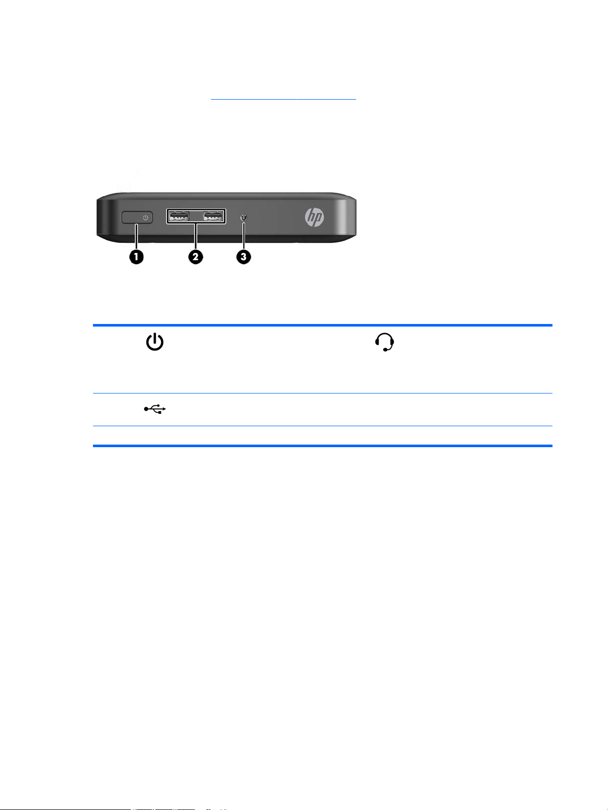
Front panel components
For more information, go to http://www.hp.com/go/quickspecs and search for your specic thin client model
to nd the model-specic QuickSpecs.
(1) Power button (3) Headset jack
This connector supports audio out
(speakers and headphones) or a
headset (with headphones and a
microphone).
(2) Hi-Speed universal serial bus (USB)
2.0 connectors (2)
NOTE: The thin client does not include an internal PC speaker; it requires the addition of an external speaker device to produce audio.
2 Chapter 1 Product features
Page 9
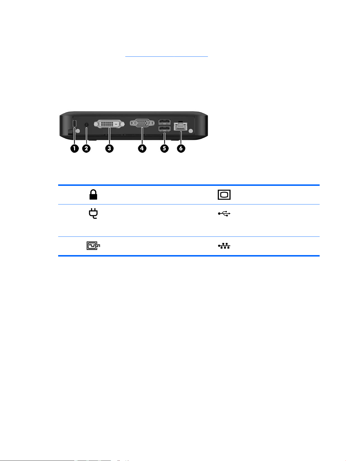
Rear panel components
For more information, go to http://www.hp.com/go/quickspecs and search for your specic thin client model
to nd the model-specic QuickSpecs.
(1) Cable lock slot (4) VGA connector
(2) Power connector (5) Hi-Speed universal serial bus (USB)
2.0 connectors (2)
These ports are typically used to
connect the mouse and keyboard.
(3) DVI-D connector (6) Ethernet RJ-45 connector
Rear panel components 3
Page 10
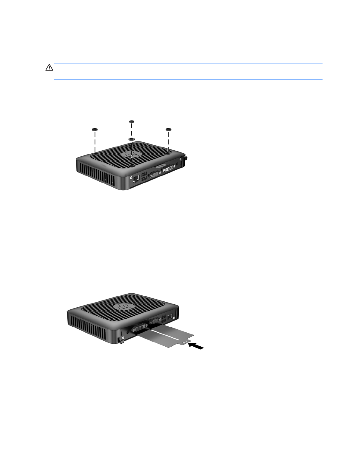
Removing the rubber feet
The thin client comes with rubber feet installed. The rubber feet help keep the thin client safely in place.
CAUTION: If you use the thin client in a horizontal orientation without the rubber feet, it may slide and
result in equipment damage.
The rubber feet may be removed, if required.
Serial number location
Every thin client includes a unique serial number located as shown in the following illustration. Have this
number available when contacting HP customer service for assistance.
4 Chapter 1 Product features
Page 11

2 Hardware changes
Warnings and cautions
Before performing upgrades be sure to carefully read all of the applicable instructions, cautions, and
warnings in this guide.
WARNING! To reduce the risk of personal injury or equipment damage from electric shock, hot surfaces, or
re:
Disconnect the power cord from the power outlet and allow the internal system components to cool before
you touch them.
Do not plug telecommunications or telephone connectors into the network interface controller (NIC)
receptacles.
Do not disable the power cord grounding plug. The grounding plug is an important safety feature.
Plug the power cord into a grounded (earthed) outlet that is easily accessible at all times.
To reduce the risk of serious injury, read the Safety & Comfort Guide. It describes proper workstation setup,
posture, and health and work habits for computer users, and provides important electrical and mechanical
safety information. The Safety & Comfort Guide is located on the HP website at http://www.hp.com/ergo.
WARNING! Energized parts inside.
Disconnect power to the equipment before removing the enclosure.
Replace and secure the enclosure before re-energizing the equipment.
CAUTION: Static electricity can damage the electrical components of the thin client or optional equipment.
Before beginning the following procedures, be sure that you are discharged of static electricity by briey
touching a grounded metal object. See Preventing electrostatic damage on page 39 for more information.
When the thin client is plugged into an AC power source, voltage is always applied to the system board. To
prevent damage to internal components, you must disconnect the power cord from the power source before
opening the thin client.
Warnings and cautions 5
Page 12
Removing and replacing the access panel
Removing the access panel
WARNING! To reduce the risk of personal injury or equipment damage from electric shock, hot surfaces, or
re, ALWAYS operate the thin client with the access panel in place. In addition to enhancing safety, the access
panel may provide important instructions and identication information, which may be lost if the access
panel is not used. DO NOT use any access panel except the one that is provided by HP for use with this thin
client.
Before removing the access panel, be sure that the thin client is turned o and the power cord is disconnected
from the electrical outlet.
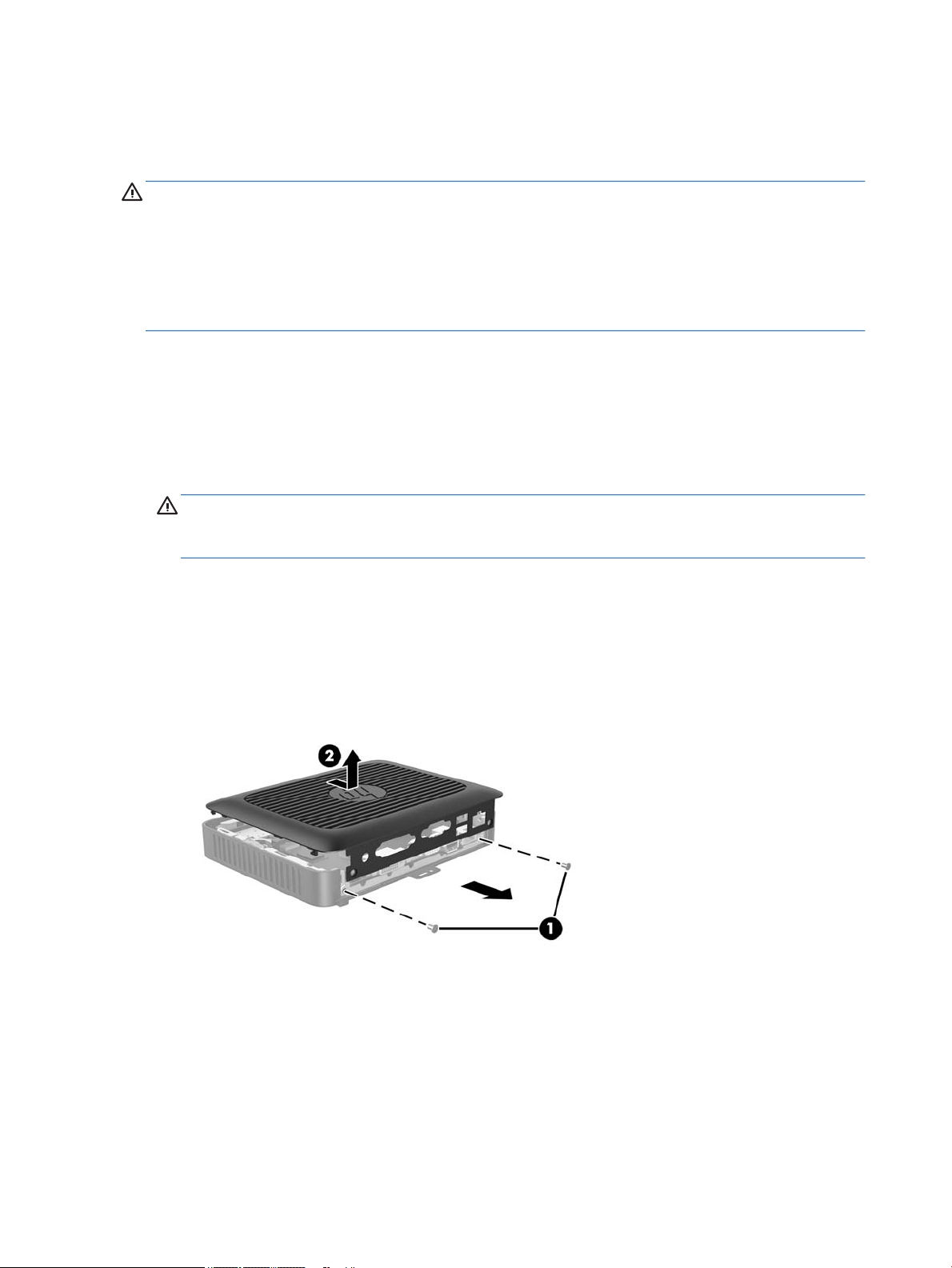
To remove the access panel:
1. Remove/disengage any security devices that prohibit opening the thin client.
2. Remove all removable media, such as USB ash drives, from the thin client.
3. Turn o the thin client properly through the operating system, and then turn o any external devices.
4. Disconnect the power cord from the power outlet, and disconnect any external devices.
CAUTION: Regardless of the power-on state, voltage is always present on the system board as long as
the system is plugged into an active AC outlet. You must disconnect the power cord to avoid damage to
the internal components of the thin client.
5. Lay the unit at on a stable surface with the right side up.
6. Remove the two screws from the back I/O panel (1).
7. Slide the access panel approximately 6 mm (.24 in) toward the back of the chassis, and then lift the
panel o of the thin client (2).
6 Chapter 2 Hardware changes
Page 13
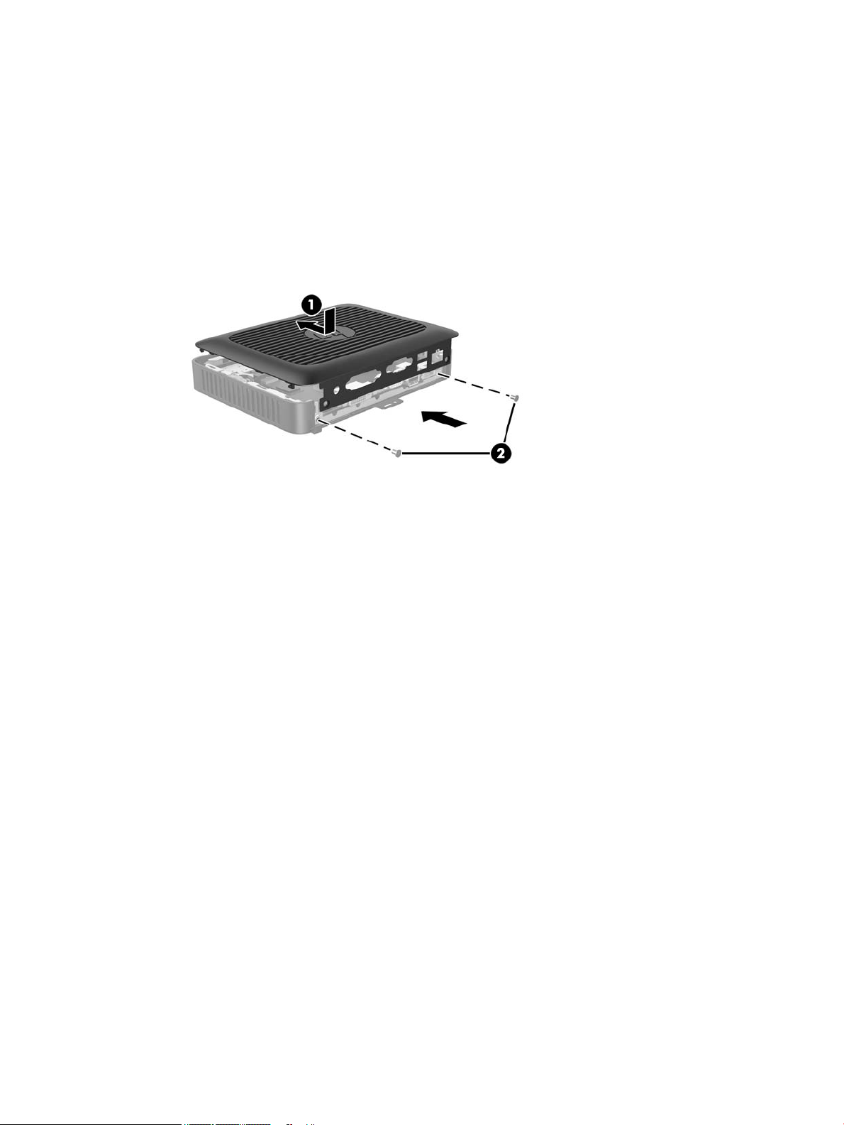
Replacing the access panel
To replace the access panel:
1. Align the tabs on each side of the access panel with the slots in the chassis. Set the access panel on the
chassis, approximately 6 mm (.24 in) inside the edge of the chassis, and then slide the panel toward the
front of the chassis (1) into place.
2. Fasten the two screws into the ends of the back I/O panel to secure the access panel (2).
Removing and replacing the access panel 7
Page 14
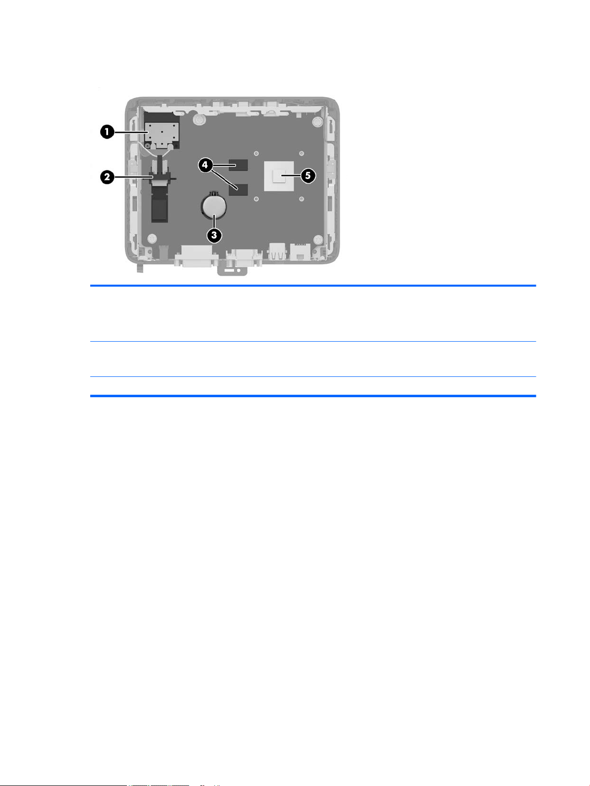
Locating internal components
1 PCIe mini card for the Wi-Fi module 4 512 MB SDRAM memory chips
2 USB 3.0 module holder with module installed 5 System on a Chip (SOC)
This thin client has four 512 MB SDRAM memory chips soldered
to the system board: two on this side and two directly below
them on the other side.
The SOC is soldered to the system board.
3 Battery
8 Chapter 2 Hardware changes
Page 15
Removing and replacing the USB 3.0 ash drive
Before returning the thin client to HP for exchange, you may choose to remove and safeguard the USB 3.0
ash drive.
Removing the USB 3.0 ash drive
WARNING! Before removing the access panel, be sure that the thin client is turned o and the power cord is
disconnected from the electrical outlet.
To remove the USB 3.0 ash drive, perform the following steps:
1. Remove/disengage any security devices that prohibit opening the thin client.
2. Remove all removable media, such as USB ash drives, from the thin client.
3. Turn o the thin client properly through the operating system, and then turn o any external devices.
4. Disconnect the power cord from the power outlet, and disconnect any external devices.
CAUTION: Regardless of the power-on state, voltage is always present on the system board as long as
the system is plugged into an active AC outlet. You must disconnect the power cord to avoid damage to
the internal components of the thin client.
5. Lay the thin client down with the right side up.
6. Remove the thin client access panel. See Removing the access panel on page 6.
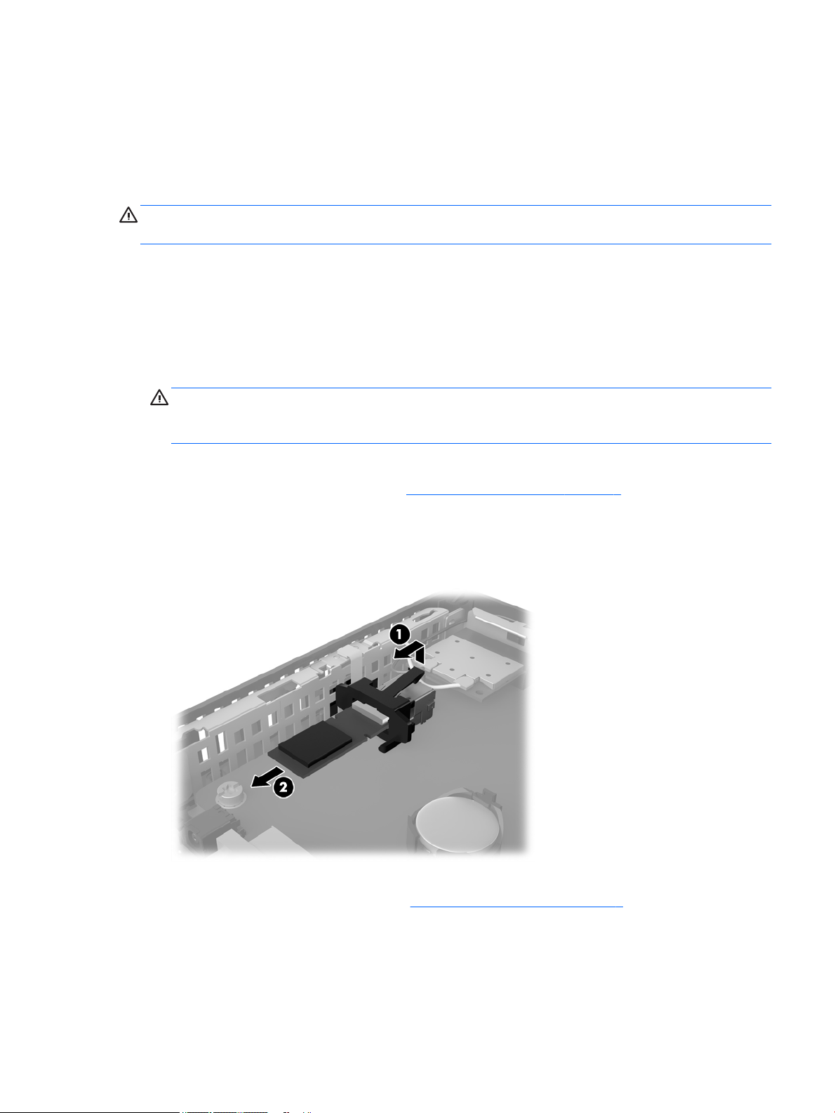
7. Locate the USB 3.0 ash drive on the system board.
8. Lift the USB holder and push it toward the USB 3.0 ash drive (1).
9. Carefully pull the ash drive out of the socket (2).
Store the USB 3.0 ash drive carefully until it can be installed in the returned thin client.
10. Replace and secure the access panel. See Replacing the access panel on page 7.
Removing and replacing the USB 3.0 ash drive 9
Page 16
Replacing the USB 3.0 ash drive
WARNING! Before removing the access panel, be sure that the thin client is turned o and the power cord is
disconnected from the electrical outlet.
To Install the USB 3.0 ash drive, perform the following steps:
1. Lay the thin client down with the right side up.
2. Remove the thin client access panel. See Removing the access panel on page 6.
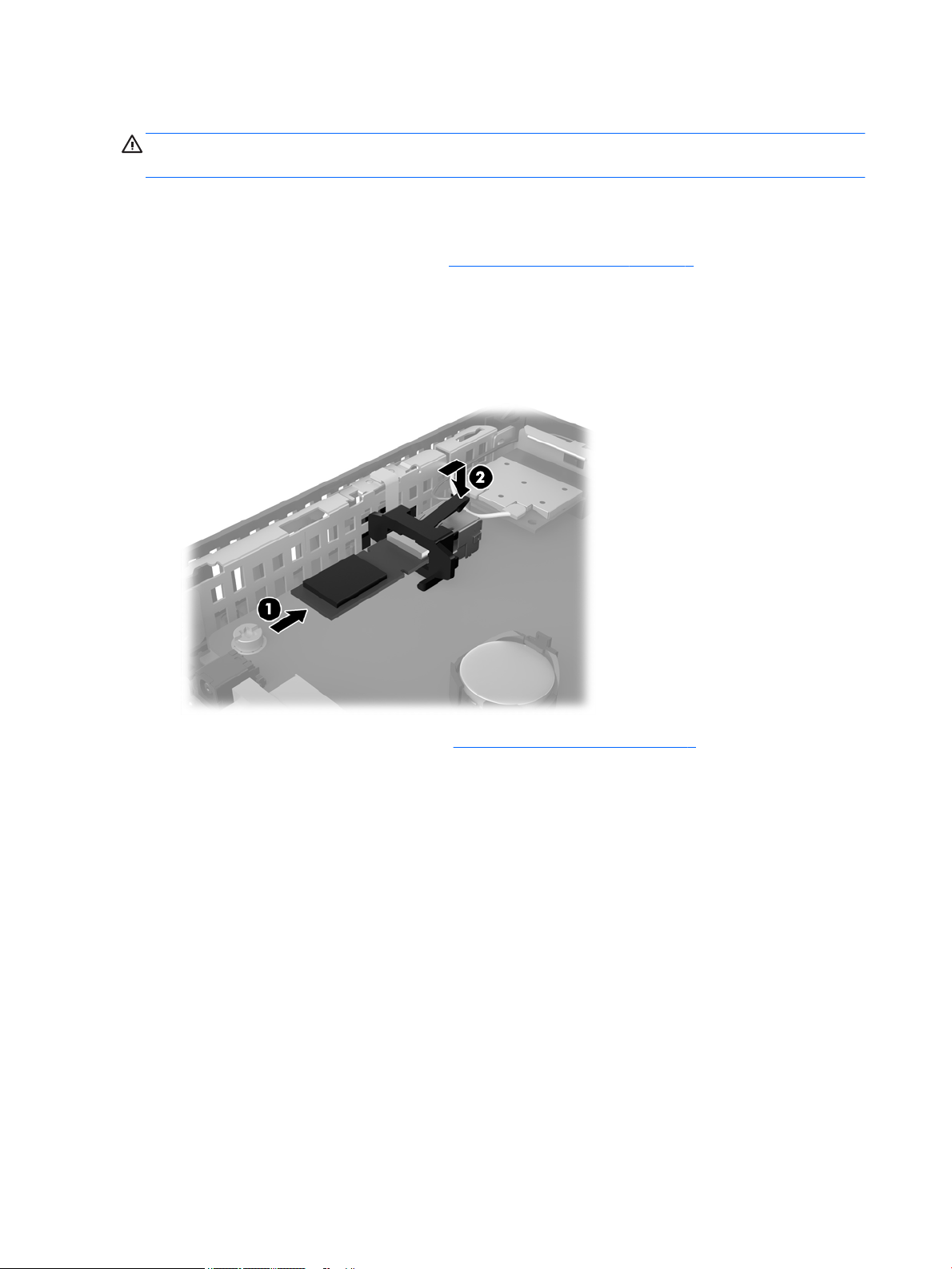
3. Locate the USB 3.0 ash drive holder on the system board.
4. Lift the USB holder and push it forward to expose the USB socket.
5. Slide the USB 3.0 ash drive rmly into the USB socket (1).
6. Push the USB holder back and press it down (2) to lock the USB 3.0 ash drive in place.
7. Replace and secure the access panel. See Replacing the access panel on page 7.
10 Chapter 2 Hardware changes
Page 17

Removing and replacing the battery
WARNING! Before removing the access panel, be sure that the thin client is turned o and the power cord is
disconnected from the electrical outlet.
To remove and replace the battery:
1. Remove/disengage any security devices that prohibit opening the thin client.
2. Remove all removable media, such as USB ash drives, from the thin client.
3. Turn o the thin client properly through the operating system, and then turn o any external devices.
4. Disconnect the power cord from the power outlet, and disconnect any external devices.
CAUTION: Regardless of the power-on state, voltage is always present on the system board as long as
the system is plugged into an active AC outlet. You must disconnect the power cord to avoid damage to
the internal components of the thin client.
5. Remove the thin client access panel. See Removing the access panel on page 6.
6. Locate the battery and battery holder on the system board.
7. Depending on the type of battery holder on the system board, complete the following instructions to
replace the battery.
Type 1
a. Lift the battery out of its holder.
b. Slide the replacement battery into position, positive side up. The battery holder automatically
secures the battery in the proper position.
Type 2
a. To release the battery from its holder, squeeze the metal clamp that extends above one edge of
the battery. When the battery pops up, lift it out (1).
Removing and replacing the battery 11
Page 18

b. To insert the new battery, slide one edge of the replacement battery under the holder’s lip with the
positive side up. Push the other edge down until the clamp snaps over the other edge of the
battery (2).
8. Replace and secure the access panel. See Replacing the access panel on page 7.
9. Replace the thin client stand.
10. Reconnect the power cord and turn on the thin client.
11. Lock any security devices that were disengaged when the thin client cover or access panel was removed.
HP encourages customers to recycle used electronic hardware, HP original print cartridges, and rechargeable
batteries. For more information about recycling programs, go to http://www.hp.com and search for “recycle”.
Batteries, battery packs, and accumulators should not be disposed of together with the general household
waste. In order to forward them to recycling or proper disposal, please use the public collection system or
return them to HP, an authorized HP partner, or their agents.
The Taiwan EPA requires dry battery manufacturing or importing rms, in accordance with Article 15 or the
Waste Disposal Act, to indicate the recovery marks on the batteries used in sales, giveaways, or promotions.
Contact a qualied Taiwanese recycler for proper battery disposal.
12 Chapter 2 Hardware changes
Page 19

A Computer Setup (F10) Utility, BIOS Settings
Computer Setup (F10) Utilities
Use Computer Setup (F10) Utility to do the following:
●
Change factory default settings.
●
Set the system date and time.
●
Set, view, change, or verify the system conguration, including settings for processor, graphics,
memory, audio, storage, communications, and input devices.
●
Modify the boot order of bootable devices such as solid-state drives or USB ash media devices.
●
Select Post Messages Enabled or Disabled to change the display status of Power-On Self-Test (POST)
messages. Post Messages Disabled suppresses most POST messages, such as memory count, product
name, and other non-error text messages. If a POST error occurs, the error is displayed regardless of the
mode selected. To manually switch to Post Messages Enabled during POST, press any key (except F1
through F12).
●
Enter the Asset Tag or property identication number assigned by the company to this computer.
●
Enable the power-on password prompt during system restarts (warm boots) as well as during power-on.
●
Establish a setup password that controls access to the Computer Setup (F10) Utility and the settings
described in this section.
●
Secure integrated I/O functionality, including the USB, audio, or embedded NIC, so that they cannot be
used until they are unsecured.
Using Computer Setup (F10) Utilities
Computer Setup can be accessed only by turning the computer on or restarting the system. To access the
Computer Setup Utilities menu, complete the following steps:
1. Turn on or restart the computer.
2. Press either Esc or F10 while the “Press the ESC key for Startup Menu” message is displayed at the
bottom of the screen.
Pressing Esc displays a menu that allows you to access dierent options available at startup.
NOTE: If you do not press Esc or F10 at the appropriate time, you must restart the computer and again
press Esc or F10 when the monitor light turns green to access the utility.
NOTE: You can select the language for most menus, settings, and messages using the Language
Selection option using the F8 key in Computer Setup.
3. If you pressed Esc, press F10 to enter Computer Setup.
4. A choice of ve headings appears in the Computer Setup Utilities menu: File, Storage, Security, Power,
and Advanced.
Computer Setup (F10) Utilities 13
Page 20

5. Use the arrow (left and right) keys to select the appropriate heading. Use the arrow (up and down) keys
to select the option you want, then press Enter. To return to the Computer Setup Utilities menu, press
Esc.
6. To apply and save changes, select File > Save Changes and Exit.
●
If you have made changes that you do not want applied, select Ignore Changes and Exit.
●
To reset to factory settings, select Apply Defaults and Exit. This option will restore the original
factory system defaults.
CAUTION: Do NOT turn the computer power OFF while the BIOS is saving the Computer Setup (F10) changes
because the CMOS could become corrupted. It is safe to turn o the computer only after exiting the F10 Setup
screen.
Heading Table
File Computer Setup—File on page 15
Storage Computer Setup—Storage on page 16
Security Computer Setup—Security on page 17
Power Computer Setup—Power on page 18
Advanced Computer Setup—Advanced on page 19
14 Appendix A Computer Setup (F10) Utility, BIOS Settings
Page 21

Computer Setup—File
NOTE: Support for specic Computer Setup options may vary depending on the hardware conguration.
Option Description
System Information Lists:
●
Manufacturer
●
Product name
●
SKU number (some models)
●
Serial number
●
Asset Tag
●
Ownership Tag
●
System Board ID
●
System Board CT Number
●
BIOS Revision
●
BIOS Date
●
Processor type
●
Processor speed
●
Memory size/speed, number of channels (single or dual) (if applicable)
●
Integrated MAC
●
WLAN FCC ID
About Displays copyright notice.
Set Time and Date Allows you to set system time and date.
Flash System ROM Allows you to update the system ROM with a BIOS image le located on removable media.
Default Setup Save Current Settings as Default
Lets the user store the current settings of the Setup options selected by the user as the default values for
all future default loading.
Restore Factory Settings as Default
Lets the user select the values of the Setup options preset by the BIOS as the default values for all future
default loading.
Apply Defaults and Exit Loads the original factory system conguration settings for use by a subsequent “Apply Defaults and
Exit” action.
Ignore Changes and Exit Exits Computer Setup without applying or saving any changes.
Save Changes and Exit Saves changes to system conguration or default settings and exits Computer Setup.
Computer Setup (F10) Utilities 15
Page 22

Computer Setup—Storage
Option Description
Device Conguration Lists all installed BIOS-controlled storage devices. When a device is selected, detailed information and
options are displayed. The following options may be presented:
Hard Disk: Size, model, rmware version, serial number.
Storage Options External USB Storage Boot
Lets you decide when to boot from external USB storage (before or after the internal USB storage) or
disable the ability to boot from USB external storage.
Legacy Support
Allows you to turn o all legacy support on the computer, including booting to DOS, running legacy
graphics cards, booting to legacy devices, and so on. If set to disable, legacy boot options in Storage >
Boot Order are not displayed. Default is enabled.
Boot Order Allows you to:
●
●
●
NOTE: You can use F5 to disable individual boot items, as well as disable EFI boot and/or legacy boot.
MS-DOS drive lettering assignments may not apply after a non-MS-DOS operating system has started.
Shortcut to Temporarily Override Boot Order
To boot one time from a device other than the default device specied in Boot Order, restart the computer
and press Esc (to access the boot menu) and then F9 (Boot Order), or only F9 (skipping the boot menu)
when the monitor light turns green. After POST is completed, a list of bootable devices is displayed. Use
the arrow keys to select the preferred bootable device and press Enter. The computer then boots from the
selected non-default device for this one time.
Specify the order in which EFI boot sources (such as a internal drive, USB hard drive, or USB optical
drive) are checked for a bootable operating system image. Each device on the list may be individually
excluded from or included for consideration as a bootable operating system source. EFI boot sources
always have precedence over legacy boot sources.
Specify the order in which legacy boot sources (such as a network interface card, internal drive, or
USB optical drive) are checked for a bootable operating system image. Each device on the list may be
individually excluded from or included for consideration as a bootable operating system source.
Specify the order of attached hard drives. The rst hard drive in the order will have priority in the
boot sequence and will be recognized as drive C (if any devices are attached).
16 Appendix A Computer Setup (F10) Utility, BIOS Settings
Page 23

Computer Setup—Security
NOTE: Support for specic Computer Setup options may vary depending on the hardware conguration.
Table A-1 Computer Setup—Security
Option Description
Setup Password Allows you to set and enable a setup (administrator) password.
NOTE: If the setup password is set, it is required to change Computer Setup options, ash the ROM, and
make changes to certain plug and play settings under Windows.
Power-On Password Allows you to set and enable a power-on password. The power-on password prompt appears after a
power cycle or reboot. If the user does not enter the correct power-on password, the unit will not boot.
Password Options
(This selection appears
only if a power-on
password or setup
password is set.)
Device Security Allows you to set Device Available/Device Hidden (default is Device Available) for:
USB Security Allows you to set enabled/disabled (default is Enabled) for:
Slot Security Allows you to disable the PCI Express slot and Mini Card Slot. Default is enabled.
Allows you to enable/disable:
Stringent Password: This item only selectable while Setup Password is set.
NOTE: Disable the on-board password jumper’s (E49) ability to reset the setup passwords.
When enabling Stringent Password, losing the passwords may render the system permanently unusable.
●
System audio
●
Network controller
●
Internal storage
●
Mini PCIe Wireless LAN Device
●
Front USB Ports
◦
USB Port 2
◦
USB Port 3
●
Rear USB Ports
◦
USB Port 0
◦
USB Port 1
●
Mini Card Slot
Network Boot Enables/disables the computer’s ability to boot from an operating system installed on a network server.
Default is enabled.
Remote Wakeup Boot Source (Local Hard Drive/Remote Server)
System IDs Lists the following information:
●
Asset tag (18-byte identier), a property identication number assigned by the company to the
computer.
●
Universal Unique Identier (UUID) number. The UUID can only be updated if the current chassis serial
number is invalid. (These ID numbers are normally set in the factory and are used to uniquely
identify the system.)
●
Product name
●
Serial Number
●
Family Name
Computer Setup (F10) Utilities 17
Page 24

Table A-1 Computer Setup—Security (continued)
●
Ownership Tag
●
Feature Byte
●
Build ID
●
Keyboard
System Security Data Execution Prevention (enable/disable) - Helps prevent operating system security breaches. Default is
enabled.
Virtualization Technology (enable/disable). Controls the virtualization features of the processor. Changing
this setting requires turning the computer o and then back on. Default is disabled.
Secure Boot
Conguration
Computer Setup—Power
NOTE: Support for specic Computer Setup options may vary depending on the hardware conguration.
Table A-2 Computer Setup—Power
Option Description
OS Power Management Runtime Power Management (Enable/Disable)
The options on this setup page are only for Windows 8 and other operating systems that support Secure
Boot. Changing the default setting of the setup options on this page for operating system that do not
support secure boot may prevent the system from booting successfully.
Legacy Support (Enable/Disable). Enable or disable the legacy operating system support (Windows
Embedded Standard 7 and HP Thin-Pro).
Secure Boot (Enable/Disable). Only when the Legacy Support set to “Disable”, this item can be set to
Enabled. This item is for Secure Boot ow control. Secure boot is possible only if system run in user mode.
Key Management
●
Clear Secure Boot Keys (Clear/Don’t Clear). Lets you clear the Secure Boot Key.
●
Key ownership (HP keys/ Customer keys). Lets you change the keys of dierent owners.
Fast Boot (Enable/Disable). Enable Fast Boot cause system boot by initializing a minimal set of devices
which is required to launch active boot option. This option has no eect for BBS boot options.
Idle Power Savings (Extended/Normal)
Hardware Power
Management
S5 Maximum Power Savings – Turns o power to all nonessential hardware when system is o.
S5 Wake on LAN (Disable/Enable). Permits the user to control whether the system should wake from S5 if
a magic packet is received by NIC.
18 Appendix A Computer Setup (F10) Utility, BIOS Settings
Page 25

Computer Setup—Advanced
NOTE: Support for specic Computer Setup options may vary depending on the hardware conguration.
Table A-3 Computer Setup—Advanced (for advanced users)
Option Heading
Power-On Options Allows you to set:
●
●
NOTE: If you turn o power to the computer using the switch on a power strip, you will not be able to
use the suspend/sleep feature or the Remote Management features.
●
BIOS Power-On Allows you to set the computer to turn on automatically at a time you specify.
Bus Options On some models, allows you to enable or disable:
●
●
POST messages (enable/disable). Default is disabled.
After Power Loss (o/on/previous state). Default is Power o. Setting this option to:
◦
Power o—causes the computer to remain powered o when power is restored.
◦
Power on—causes the computer to power on automatically as soon as power is restored.
◦
Previous state—causes the computer to power on automatically as soon as power is restored,
if it was on when power was lost.
POST Delay (in seconds). Enabling this feature will add a user-specied delay to the POST process.
This delay is sometimes needed for hard disks on some PCI cards that spin up very slowly, so slowly
that they are not ready to boot by the time POST is nished. The POST delay also gives you more
time to select F10 to enter Computer (F10) Setup. Default is None.
PCI SERR# Generation. Default is enabled.
PCI VGA Palette Snooping, which sets the VGA palette snooping bit in PCI conguration space; only
needed when more than one graphics controller is installed. Default is disabled.
Device Options Allows you to set:
●
POST Buzzer Volume (Soft/Loud/Mute). Default is Soft.
●
Num Lock State at Power-On (o/on). Default is o.
●
Multi-Processor (Enable, Disable) Default Enabled; Use this option to disable multiprocessor support
under the OS.
●
NIC Option ROM Download (PXE, disabled). The BIOS contains an embedded NIC option ROM to allow
the unit to boot through the network to a PXE server. This is typically used to download a corporate
image to a hard drive. The NIC option ROM takes up memory space below 1 MB commonly referred to
as DOS Compatibility Hole (DCH) space. This space is limited. This F10 option will allow users to
disable the downloading of this embedded NIC option ROM thus giving more DCH space for
additional PCI cards which may need option ROM space. The default will be to have the NIC optionROM-enabled. Default is PXE.
●
Integrated Graphics (Auto/Force). Use this option to manage integrated (UMA) graphics memory
allocation. The value you choose allocates memory permanently to graphics and is unavailable to
the operating system. For example, if you set this value to 512 MB on a system with 2 GB of RAM,
the system always allocates 512 MB for graphics and the other 1.5 GB for use by the BIOS and
operating system. Default is Auto which sets memory allocation to 256 MB.
If you select Force, the UMA Frame Buer Size option displays, which lets you set the UMA memory
size allocation between 64 MB and 512 MB. Default is 256 MB.
Computer Setup (F10) Utilities 19
Page 26

Changing BIOS Settings from the HP BIOS Congure Utility
(HPBCU)
Some BIOS settings may be changed locally within the operating system without having to go through the
F10 utility. This table identies the items that can be controlled with this method.
BIOS Setting Default Value Other Values
Language English Francais, Espanol, Deutsch, Italiano, Dansk, Suomi, Nederlands, Norsk,
Portugues, Svenska, Japanese, Simplied Chinese
Set Time 00:00 00:00:23:59
Set Day 01/01/2011 01/01/2011 to current date
Default Setup None Save Current Settings as Default, Restore Factory Settings as Default
Apply Defaults and Exit Disable Enable
Setup Browse Mode Enable Disable
USB Storage Boot Enable Disable
System Audio Device available Device hidden
Network Controller Device available Device hidden
Mini PCIe Wireless LAN Device Enable Disable
Front USB Ports Enable Disable
Rear USB Ports Enable Disable
Front USB Port 8 & 9 Enable Disable
Rear USB Port 0, 1, 2, & 3 Enable Disable
USB Port Conguration Auto Force 2.0
Mini Card Slot Enable Disable
Network Boot Enable Disable
Remote Wakeup Boot Source Local Hard Drive Remote Server
Data Execution Prevention Enable Disable
Virtualization Technology Disable Enable
Legacy Support Enable Disable (Note: The default value may be varied depends on the OS)
Secure Boot Disable Enable (Note: The default value may be varied depends on the OS)
Clear Secure Boot Keys Don’t Clear Clear
Key Ownership HP Keys Custom Keys
Fast Boot Disable Enable (Note: The default value may be varied depends on the OS)
Runtime Power Management Enable Disable
Idle Power Savings Extended Normal
S5 Maximum Power Savings Disable Enable
S5 Wake on LAN Disable Enable
20 Appendix A Computer Setup (F10) Utility, BIOS Settings
Page 27

POST Messages Disable Enable
After Power Loss O On, Previous State
POST Delay (in seconds) None 5, 10, 15, 20, 60
Power on Sunday – Saturday Disable Enable
Power on Time (hh:mm) 00:00 00:00:23:59
PCI SERR# Generation Enable Disable
PCI VGA Palette Snooping Disable Enable
Num Lock State at Power- On On O
Integrated Graphics Auto Disable, Force
UMA Frame Buer Size 512M 32M, 64M, 128M, 256M, 1G
Multi-Processor Enable Disable
Internal Speaker Enable Disable
NIC Option ROM Download PXE Disable
Changing BIOS Settings from the HP BIOS Congure Utility (HPBCU) 21
Page 28

B Diagnostics and Troubleshooting
LEDs
LED Status
Power LED O When the unit is plugged into the wall socket and the Power LED is o, the unit is powered o.
However, the network can trigger a Wake On LAN event in order to perform management functions.
Power LED On Displays during boot sequence and while the unit is on. During boot sequence, hardware initialization is
processed and startup tests are performed on the following:
●
Processor initialization
●
Memory detection and initialization
●
Video detection and initialization
NOTE: If one of the tests fails, the unit will simply stop, but the LED will stay on. If the video test fails,
the unit beeps. There are no messages sent to video for any of these failed tests.
NOTE: After the video is initialized, anything that fails will have an error message.
NOTE: RJ-45 LEDs are located inside the RJ-45 connector on the top, rear panel of the thin client. The LEDs are visible when the
connector is installed. Blinking green indicates network activity, and amber indicates a 100MB speed connection.
Wake-on LAN
Wake-on LAN (WOL) allows a computer to be turned on or resumed from sleep or hibernation state by a
network message. You can enable or disable WOL in Computer Setup using the S5 Maximum Power Savings
setting.
To enable or disable WOL:
1. Turn on or restart the computer.
2. Press either Esc or F10 while the “Press the ESC key for Startup Menu” message is displayed at the
bottom of the screen.
NOTE: If you do not press Esc or F10 at the appropriate time, you must restart the computer and again
press Esc or F10 when the monitor light turns green to access the utility.
3. If you pressed Esc, press F10 to enter Computer Setup.
4. Navigate to Power > Hardware Power Management.
5. Set S5 Maximum Power Savings as follows:
●
Disable WOL = Enabled
●
Enable WOL = Disabled
6. Press F10 to accept any changes.
7. Select File > Save Changes and Exit.
22 Appendix B Diagnostics and Troubleshooting
Page 29

Power-On Sequence
At power-on, the ash boot block code initializes the hardware to a known state, then performs basic poweron diagnostic tests to determine the integrity of the hardware. Initialization performs the following functions:
1. Initializes CPU and memory controller.
2. Initializes and congures all PCI devices.
3. Initializes VGA software.
4. Initializes the video to a known state.
5. Initializes USB devices to a known state.
6. Performs power-on diagnostics. For more information, see “Power-On Diagnostic Tests”.
7. The unit boots the operating system.
Resetting the Setup and power-on Passwords
You can reset the Setup and Power-on passwords as follows:
1. Turn o the computer and disconnect the power cord from the power outlet.
2. Remove the side access panel and the metal side cover.
3. Remove the password jumper from the system board header labeled PSWD/E49.
4. Replace the metal side cover and the side access panel.
5. Connect the computer to AC power, and then turn on the computer.
6. Turn o the computer and disconnect the power cord from the power outlet.
7. Remove the side access panel and the metal side cover.
8. Replace the password jumper.
9. Replace the metal side cover and the side access panel.
Power-On Sequence 23
Page 30

Power-On Diagnostic Tests
The Power-on diagnostics performs basic integrity tests of the hardware to determine its functionality and
conguration. If a diagnostic test fails during hardware initialization the unit simply stops. There are no
messages sent to video.
NOTE: You may try to restart the unit and run through the diagnostic tests a second time to conrm the rst
shutdown.
The following table lists the tests that are performed on the unit.
Test Description
Boot Block Checksum Tests boot block code for proper checksum value
DRAM Simple write/read pattern test of the rst 640k of memory
Serial Port Tests the serial port using simple port verication test to determine if ports are present
Timer Tests timer interrupt by using polling method
RTC CMOS battery Tests integrity of RTC CMOS battery
NAND ash device Tests for proper NAND ash device ID present
Interpreting POST Diagnostic Front Panel LEDs and Audible Codes
This section covers the front panel LED codes as well as the audible codes that may occur before or during
POST that do not necessarily have an error code or text message associated with them.
WARNING! When the computer is plugged into an AC power source, voltage is always applied to the system
board. To reduce the risk of personal injury from electrical shock and/or hot surfaces, be sure to disconnect
the power cord from the wall outlet and allow the internal system components to cool before touching.
NOTE: Recommended actions in the following table are listed in the order in which they should be
performed.
Not all diagnostic lights and audible codes are available on all models.
Table B-1 Diagnostic Front Panel LEDs and Audible Codes
Activity Beeps Possible Cause Recommended Action
White Power LED On. None Computer on. None
White Power LED ashes every
two seconds.
Red Power LED ashes two
times, once every second,
followed by a two second pause.
Beeps stop after fth iteration
but LEDs continue until problem
is solved.
None Computer in Suspend to
RAM mode (some models
only) or normal Suspend
mode.
2 Processor thermal
protection activated:
A fan may be blocked or not
turning.
OR
None required. Press any key or move the mouse to
wake the computer.
1. Ensure that the computer air vents are not
blocked and the processor cooling fan is
plugged in and running, if equipped.
2. Contact an authorized reseller or service
provider.
24 Appendix B Diagnostics and Troubleshooting
Page 31

Table B-1 Diagnostic Front Panel LEDs and Audible Codes (continued)
Activity Beeps Possible Cause Recommended Action
The heat sink/fan assembly
is not properly attached to
the processor.
OR
The unit has vents blocked
or is in a location where the
ambient temperature is too
high.
Red Power LED ashes four
times, once every second,
followed by a two second pause.
Beeps stop after fth iteration
but LEDs continue until problem
is solved.
Red Power LED ashes ve
times, once every second,
followed by a two second pause.
Beeps stop after fth iteration
but LEDs continue until problem
is solved.
Red Power LED ashes six times,
once every second, followed by a
two second pause. Beeps stop
after fth iteration but LEDs
continue until problem is solved.
4 Power failure (power supply
is overloaded).
OR
The incorrect external
power supply adapter is
being used on the unit.
5 Pre-video memory error. CAUTION: To avoid damage to the memory
6 Pre-video graphics error. For systems with a graphics card:
1. Check if a device is causing the problem by
removing ALL attached devices. Power on the
system. If the system enters the POST, then
power o and replace one device at a time and
repeat this procedure until failure occurs.
Replace the device that is causing the failure.
Continue adding devices one at a time to
ensure all devices are functioning properly.
2. Replace the power supply.
3. Replace the system board.
modules or the system board, you must unplug the
computer power cord before attempting to reseat,
install, or remove a memory module.
1. Reseat memory modules.
2. Replace memory modules one at a time to
isolate the faulty module.
3. Replace third-party memory with HP memory.
4. Replace the system board.
1. Reseat the graphics card.
2. Replace the graphics card.
3. Replace the system board.
For systems with integrated graphics, replace the
system board.
Red Power LED ashes eight
times, once every second,
followed by a two second pause.
Beeps stop after fth iteration
but LEDs continue until problem
is solved.
System does not power on and
LEDs are not ashing.
8 Invalid ROM based on bad
checksum.
None System unable to power on. Press and hold the power button for less than 4
1. Reash the system ROM with the latest BIOS
image using the BIOS Recovery procedure.
2. Replace the system board.
seconds. If the hard drive LED turns white, the power
button is working correctly. Try the following:
1. Remove the power cord from the computer.
2. Open the computer and press the yellow CMOS
button on the system board for 4 seconds
(located near the front USB ports).
Interpreting POST Diagnostic Front Panel LEDs and Audible Codes 25
Page 32

Table B-1 Diagnostic Front Panel LEDs and Audible Codes (continued)
Activity Beeps Possible Cause Recommended Action
3. Verify that the AC cord is plugged into the
power supply.
4. Close the unit and reattach the power cord.
5. Try to power on the computer.
6. Replace the unit.
POST Numeric Codes and Text Messages
This section covers those POST errors that have numeric codes associated with them. The section also
includes some text messages that may be encountered during POST.
NOTE: The computer will beep once after a POST text message is displayed on the screen.
Table B-2 Numeric Codes and Text Messages
Control panel message Description Recommended action
103-System Board Failure DMA or timers. 1. Clear CMOS.
2. Remove expansion boards.
3. Replace the system board.
110-Out of Memory Space for Option ROMs Recently added PCI expansion card contains an
option ROM too large to download during POST.
161-Real-Time Clock Power Loss Invalid time or date in conguration memory.
RTC (real-time clock) battery may need to
be replaced.
164-MemorySize Error Memory amount has changed since the last
boot (memory added or removed).
201-Memory Error RAM failure. 1. Ensure memory modules are correctly
1. If a PCI expansion card was recently
added, remove it to see if the problem
remains.
2. In Computer Setup, set Advanced >
Device Options > NIC PXE Option ROM
Download to DISABLE to prevent PXE
option ROM for the internal NIC from being
downloaded during POST to free more
memory for an expansion card's option
ROM. Internal PXE option ROM is used for
booting from the NIC to a PXE server.
Reset the date and time under Control Panel
(Computer Setup can also be used). If the
problem persists, replace the RTC battery. See
the Removal and Replacement section for
instructions on installing a new battery, or
contact an authorized dealer or reseller for RTC
battery replacement.
Press the F1 key to save the memory changes.
installed.
2. Verify proper memory module type.
3. Remove and replace the identied faulty
memory module(s).
26 Appendix B Diagnostics and Troubleshooting
Page 33

Table B-2 Numeric Codes and Text Messages (continued)
Control panel message Description Recommended action
4. If the error persists after replacing
memory modules, replace the system
board.
214-DIMM Conguration Warning Populated DIMM Conguration is not optimized. Rearrange the DIMMs so that each channel has
the same amount of memory.
301-Keyboard Error Keyboard failure. 1. Reconnect keyboard with computer
turned o.
2. Check connector for bent or missing pins.
3. Ensure that none of the keys are
depressed.
4. Replace keyboard.
510-Flash Screen Image Corrupted Flash Screen image has errors. Reash the system ROM with the latest BIOS
image.
512-Chassis, Rear Chassis, or Front Chassis Fan
not Detected
513-Front Chassis fan not detected Front chassis fan is not connected or may have
912-Computer Cover Has Been Removed Since
Last System Startup
921-Device in PCI Express slot failed to initialize There is an incompatibility/problem with this
1720-SMART Hard Drive Detects Imminent
Failure
Invalid Electronic Serial Number Electronic serial number is missing. Enter the correct serial number in Computer
Chassis, rear chassis, or front chassis fan is not
connected or may have malfunctioned.
malfunctioned.
Computer cover was removed since last system
startup.
device and the system or PCI Express Link could
not be retrained to an x1.
Hard drive is about to fail. (Some hard drives
have a hard drive rmware patch that will x an
erroneous error message.)
1. Reseat chassis, rear chassis, or front
chassis fan.
2. Reseat fan cable.
3. Replace chassis, rear chassis, or front
chassis fan.
1. Reseat front chassis fan.
2. Reseat fan cable.
3. Replace front chassis fan.
No action required.
Try rebooting the system. If the error reoccurs,
the device may not work with this system
1. Determine if hard drive is giving correct
error message. Run the Drive Protection
System test using F2 Diagnostics.
2. Apply hard drive rmware patch
if applicable. (Available at
http://www.hp.com/support.)
3. Back up contents and replace hard drive.
Setup.
Network Server Mode Active and No Keyboard
Attached
Keyboard failure while Network Server Mode
enabled.
1. Reconnect keyboard with computer
turned o.
2. Check connector for bent or missing pins.
3. Ensure that none of the keys are
depressed.
4. Replace keyboard.
POST Numeric Codes and Text Messages 27
Page 34

Troubleshooting
Basic Troubleshooting
If the thin client is experiencing operating problems or will not power on, review the following items.
Table B-3 Power-On Troubleshooting
Issue Procedures
The thin client unit is experiencing operating
problems.
The thin client unit does not power on. 1. Verify that the power supply is good by installing it on a known working unit
The thin client unit powers on and displays a
splash screen, but does not connect to the
server.
No link or activity on the network RJ-45 LEDs or
the LEDs do not illuminate blinking green after
powering on the thin client unit. (The network
LEDs are located inside the RJ-45 connector on
the top, rear panel of the thin client. Indicator
lights are visible when the connector is
installed.)
Ensure that the following connectors are securely plugged into the thin client unit:
Power connector, keyboard, mouse, network RJ-45 connector, monitor
and testing it. If the power supply does not work on the test unit, replace the
power supply.
2. If the unit does not work properly with the replaced power supply, have the
unit serviced.
1. Verify that the network is operating and the network cable is working
properly.
2. Verify that the unit is communicating with the server by having the System
Administrator ping the unit from the server:
●
If the thin client pings back, then the signal was accepted and the unit is
working. This indicates a conguration issue.
●
If the thin client does not ping back and the thin client does not connect
to the server, re-image the unit.
1. Verify that the network is not down.
2. Make sure the RJ-45 cable is good by installing the RJ-45 cable onto a known
working device—if a network signal is detected then the cable is good.
3. Verify the power supply is good by replacing the power cable to the unit with
a known working power supply cable and testing it.
4. If network LED's still do not light and you know the power supply is good,
then re-image the unit.
5. If network LED’s still do not light, run the IP conguration procedure.
6. If network LED’s still do not light, have the unit serviced.
A newly connected unknown USB peripheral
does not respond or USB peripherals connected
prior to the newly connected USB peripheral will
not complete their device actions.
Video does not display. 1. Verify that the monitor brightness is set to a readable level.
28 Appendix B Diagnostics and Troubleshooting
An unknown USB peripheral may be connected and disconnected to a running
platform as long as you do not reboot the system. If problems occur, disconnect
the unknown USB peripheral and reboot the platform.
2. Verify the monitor is good by connecting it to a known working computer and
ensure its front LED turns green (assuming the monitor is Energy Star
compliant). If the monitor is defective, replace it with a working monitor and
repeat testing.
3. Re-image the thin client unit and power on the monitor again.
4. Test the thin client unit on a known working monitor. If the monitor does not
display video, replace the thin client unit.
Page 35

Diskless (No-Flash) Unit Troubleshooting
Because there is no ATA Flash in this model the boot priority sequence is:
●
USB device
●
PXE
1. When the unit boots, the monitor should display the following information:
Table B-4 Diskless Unit Troubleshooting
Item Information Action
MAC Address NIC portion of the system board is OK If no MAC Address, the system board is at fault. Contact the
GUID General system board information If no GUID information, the system board is at fault and
Client ID Information from server If no Client ID information there is no network connection.
MASK Information from server If no MASK information there is no network connection. This
DHCP IP Information from server If no DHCP IP information there is no network connection.
Call Center for service.
should be replaced.
This may be caused by a bad cable, the server is down, or a
bad system board. Contact the Call Center for service for the
bad system board.
may be caused by a bad cable, the server is down, or a bad
system board. Contact the Call Center for service for the bad
system board.
This may be caused by a bad cable, the server is down, or a
bad system board. Contact the Call Center for service for the
bad system board.
If you are running in an Microsoft RIS PXE environment go to step 2.
If you are running in a Linux environment go to step 3.
2. If you are running in a Microsoft RIS PXE environment press the F12 key to activate the network service
boot as soon as the DHCP IP information appears on the screen.
If the unit does not boot to the network the server is not congured to PXE.
If you missed the F12 cue, the system will try to boot to the ATA ash that is not present. The message
on the screen will read: ERROR: Non-system disk or disk error. Replace and press any key when ready.
Pressing any key will restart the boot cycle.
3. If you are running in a Linux environment an error message will appear on the screen if there is no Client
IP. ERROR: Non-system disk or disk error. Replace and press any key when ready.
Troubleshooting 29
Page 36

Conguring a PXE Server
NOTE: All PXE software is supported by authorized service providers on a warranty or service contract basis.
Customers that call the HP Customer Service Center with PXE issues and questions should be referred to their
PXE provider for assistance.
Additionally, refer to the following:
– For Windows 2008 R2: http://support.microsoft.com/kb/891275
– For Windows 2012: http://technet.microsoft.com/en-us/library/cc766320(WS.10).aspx
The services listed below must be running, and they may be running on dierent servers:
1. Domain Name Service (DNS)
2. Remote Installation Services (RIS)
NOTE: Active Directory DHCP is not required, but is recommended.
30 Appendix B Diagnostics and Troubleshooting
Page 37

C HP ThinUpdate (add-on only)
HP ThinUpdate is an image update and recovery tool that quickly and easily downloads an image to a USB
ash drive for deployment. The tool can either be installed on the thin client itself or on a standard desktop or
notebook computer.
To use HP ThinUpdate:
1. In the Control Panel, click HP ThinUpdate.
2. Select the platform, operating system, and image version.
NOTE: You can view the release notes for the selected image by clicking Release Notes.
3. Insert a USB ash drive that is larger than the size specied in the Summary pane. The required size
varies depending on the image.
4. Click Create USB and accept any End User License Agreement that is displayed. The USB ash drive is
then formatted, and then the image is downloaded to it.
NOTE: You cannot cancel the process while the USB ash drive is being formatted, but you can cancel
at any other time during the process by clicking Abort.
NOTE: Windows will detect the formatted USB ash drive as a 1 GB drive that uses the FAT32 le
system. This is because the USB ash drive is formatted with two partitions. The FAT32 partition
contains the boot instructions. A second partition, which uses the NTFS le system, contains the actual
image but will not be detected by Windows when you are viewing the drive contents.
5. When the process is complete, do one of the following:
●
If you are running HP ThinUpdate on a thin client, you will be prompted to install the image on that
thin client. Click either Yes or No.
●
If you are running HP ThinUpdate on a standard desktop or notebook computer, remove the USB
ash drive, insert it into the thin client you want to re-image, and then restart the thin client.
31
Page 38

D Device management
The t420 includes a license for HP Device Manager and has a Device Manager agent pre-installed. HP Device
Manager is a thin client optimized management tool used to manage the full life cycle of HP thin clients to
include Discover, Asset Management, Deployment and Conguration. For more information on HP Device
Manager, please visit www.hp.com/go/hpdm.
If you wish to manage the t420 with other management tools such as Microsoft SCCM or LANDesk, go to
www.hp.com/go/clientmanagement for more information.
32 Appendix D Device management
Page 39

E Adding an Image Restore Tool
1. Ensure that the boot order is set to use the Network as the rst boot device.
2. Ensure that IBR.exe (Image Restore) and Flash.dd are stored in the same directory on the server. (e.g.,
c:\program files\altiris\express\deployment server\images)
3. From the Altiris Deployment Server Console, click File > New > Job .
4. Enter a unique name for the job that you will use to deploy the original thin client image.
5. Click the name of the new job.
6. Near the upper right side of the screen, click Add.
7. Select Run Script from the menu.
8. Type [full path]images\ibr\exe-y\images\ash.xx hd0
NOTE: Linux uses the le name FLASH.DD while other operating system images use FLASH.IMG
9. Under In which OS would you like to run this script? Click DOS.
10. Click Finish.
11. You can now drag and drop the job onto the appropriate machine(s) or schedule it to run later,
depending on your needs. Refer to the documentation for Altiris Deployment Solution
(http://www.altiris.com/support/documentation) for more detailed information.
33
Page 40

F System BIOS
Updating or restoring a BIOS
HP Device Manager
HP Device Manager can be used to update the BIOS of a thin client. Customers can use a pre-built BIOS add-on
or can use the standard BIOS upgrade package along with an HP Device Manager File and Registry template.
For more information on HP Device Manager File and Registry templates, review the HP Device Manager User
Guide found at www.hp.com/go/hpdm.
Windows BIOS Flashing
You can use the BIOS Flash Update SoftPaq to restore or upgrade the system BIOS. Several methods for
changing the BIOS rmware stored on your computer are available.
The BIOS executable is a utility designed to ash the System BIOS within a Microsoft Windows environment.
To display the available options for this utility, launch the executable le under the Microsoft Windows
environment.
You can run the BIOS executable with or without the USB storage device. If the system does not have a USB
storage device installed, the BIOS update will perform under the Microsoft Windows environment and
followed by system reboot.
Linux BIOS Flashing
You can use the hp-ash utility and its associated driver to update the BIOS on systems running Linux. After
the driver loads, execute the utility from a command prompt with administrator privileges. The HP ThinPro or
HP Smart Client Linux OS images include the utility for updating the BIOS, but the binary le to ash must be
copied from the DOS Flash folder to the unit. Review the README.txt le for more specic instructions in the
SoftPaq. The Linux Flash folder also contains the les necessary to build the BIOS ash driver module for the
particular kernel being used; the hp-ash utility is not kernel-dependent other than the choice of 32-bit
(i686) and 64-bit (x86_64) avors.
BootBlock Emergency Recovery Mode
In the event of a failed BIOS update (for example if power is lost while updating), the System BIOS may
become corrupted. BootBlock Emergency Recovery Mode detects this condition and automatically searches
the root directory of the hard drive and any USB media sources for a compatible binary image. Copy the binary
(.bin) le in the DOS Flash folder to the root of the desired storage device, and then power on the system.
Once the recovery process locates the binary image, it attempts the recovery process. The automatic recovery
continues until it successfully restores or updates the BIOS. If the system has a BIOS Setup password, you may
need to use the Startup Menu / Utilities submenu to ash the BIOS manually after providing the password.
Sometimes there are restrictions on which BIOS versions are allowed to be installed on a platform. If the BIOS
that was on the system had restrictions, then only allowable BIOS versions may be used for recovery.
34 Appendix F System BIOS
Page 41

G Power cord set requirements
The power supplies on some computers have external power switches. The voltage select switch feature on
the computer permits it to operate from any line voltage between 100-120 or 220-240 volts AC. Power
supplies on those computers that do not have external power switches are equipped with internal switches
that sense the incoming voltage and automatically switch to the proper voltage.
The power cord set received with the computer meets the requirements for use in the country where you
purchased the equipment.
Power cord sets for use in other countries must meet the requirements of the country where you use the
computer.
General requirements
The requirements listed below are applicable to all countries:
1. The power cord must be approved by an acceptable accredited agency responsible for evaluation in the
country where the power cord set will be installed.
2. The power cord set must have a minimum current capacity of 10A (7A Japan only) and a nominal voltage
rating of 125 or 250 volts AC, as required by each country’s power system.
3. The diameter of the wire must be a minimum of 0.75 mm2 or 18AWG, and the length of the cord must be
between 1.8 m (6 feet) and 3.6 m (12 feet).
The power cord should be routed so that it is not likely to be walked on or pinched by items placed upon it or
against it. Particular attention should be paid to the plug, electrical outlet, and the point where the cord exits
from the product.
WARNING! Do not operate this product with a damaged power cord set. If the power cord set is damaged in
any manner, replace it immediately.
Japanese power cord requirements
For use in Japan, use only the power cord received with this product.
CAUTION: Do not use the power cord received with this product on any other products.
General requirements 35
Page 42

Country-specic requirements
Additional requirements specic to a country are shown in parentheses and explained below.
Country Accrediting Agency Country Accrediting Agency
Australia (1)
Austria (1)
Belgium (1)
Canada (2)
Denmark (1)
Finland (1)
France (1)
Germany (1)
1. The exible cord must be Type HO5VV-F, 3-conductor, 0.75mm2 conductor size. Power cord set ttings (appliance coupler and
wall plug) must bear the certication mark of the agency responsible for evaluation in the country where it will be used.
2. The exible cord must be Type SVT or equivalent, No. 18 AWG, 3-conductor. The wall plug must be a two-pole grounding type
with a NEMA 5-15P (15A, 125V) or NEMA 6-15P (15A, 250V) conguration.
3. Appliance coupler, exible cord, and wall plug must bear a “T” mark and registration number in accordance with the Japanese
Dentori Law. Flexible cord must be Type VCT or VCTF, 3-conductor, 0.75 mm2 conductor size. Wall plug must be a two-pole
grounding type with a Japanese Industrial Standard C8303 (7A, 125V) conguration.
EANSW
OVE
CEBC
CSA
DEMKO
SETI
UTE
VDE
Italy (1)
Japan (3)
Norway (1)
Sweden (1)
Switzerland (1)
United Kingdom (1)
United States (2)
IMQ
METI
NEMKO
SEMKO
SEV
BSI
UL
36 Appendix G Power cord set requirements
Page 43

H Statement of Volatility
Thin Client products typically have three types of memory devices namely, RAM, ROM, and Flash memory
devices. Data stored in the RAM memory device will be lost once the power is removed from the device. RAM
devices could be powered by main, aux, or battery power (power states are explained below). Therefore, even
when the unit is not connected to an AC outlet, some of the RAM devices could be powered by battery power.
Data stored in the ROM or Flash memory devices will retain its data even if the power is removed to the
device. Manufacturers of Flash device usually specify a period of time (in the order of 10 years) for data
retention.
Denition of power states:
Main Power: Power available when the unit is turned on.
Aux or Standby power: Power available when the unit is in o state when the power supply is connected to
an active AC outlet.
Battery Power: Power from a coin battery present in the Thin Client systems.
The table below lists the available memory devices and their types per the models. Please note that the Thin
Client systems do not use traditional hard drives with moving parts. Instead, they use ash memory devices
with an IDE front end interface. Hence, the operating systems interface with these ash devices similar to a
regular IDE hard drive. This IDE ash device contains the image of the operating system. The ash device can
only be written by an administrator. A special software tool is required to format the ash devices and clear
the data stored in them.
Please nd below a list of steps that should be taken to update BIOS and use it to set the BIOS settings to
factory default settings.
1. Download the latest BIOS (system ROM) from the HP website.
2. Follow the instructions to ash the BIOS that are found on the website.
Flashing the BIOS will reset it back to factory settings.
3. Turn on the system, and while system is powering on, and after the HP splash screen, press the F10 key
to enter BIOS setup screen.
4. If the Ownership Tag or Asset Tag is set, manually clear it under Security > System Ids.
5. Select File > Save Changes and Exit.
6. To clear the Setup or Power-On passwords if set, and clear any other settings, power down the computer
and remove the AC power cord and the computer hood.
7. Locate the (blue/green) two pin password jumper on header E49 (labeled PSWD) and remove it.
8. Remove the AC power, wait 10 seconds until the unit AC power has drained out, then press the clear
CMOS button. This is typically a yellow push button (labeled CMOS).
9. Replace the hood and AC power cord and turn the computer on. The passwords are now cleared and all
other user-congurable, non-volatile memory settings are reset to their factory default values.
10. Enter the F10 setup utility.
11. Select File > Default Setup > Restore Factory Settings as Default. This will set the default settings
back to the factory defaults.
37
Page 44

12. Select File > Apply Defaults and Exit.
13. Shut down the computer, remove the AC power cord and place the (blue/green) jumper back on header
E49. Replace the computer hood and power cord.
Model Description Location/Size Power Loss of data Comments
System Boot ROM
(BIOS)
System memory
(RAM)
RTC (CMOS) RAM RTC RAM is 256
t420
Keyboard/mouse
(ROM)
Keyboard/mouse
(RAM)
SPI ROM (64 Mbit)
socketed,
removable.
SODIMM socket.
Removable (4GB/
8GB)
bytes RAM Memory
embedded in AMD
APU’s System on
Chip (SOC).
2k bytes embedded
in the super I/O
controller (SIO12)
256 bytes
embedded in the
super I/O controller
(SIO12)
Main power If main power is
removed
Main/battery If battery power is
removed
Main
Main If main power is
removed
Only S0/S3/S5/G3
ACPI states are
supported
The information contained herein is subject to change without notice.
The only warranties for HP products and services are set forth in the express warranty statements
accompanying such products and services. Nothing herein should be construed as constituting an additional
warranty. HP shall not be liable for technical or editorial errors or omissions contained herein.
If you require additional information or need assistance please contact Charlie Shaver at 281-518-7453.
38 Appendix H Statement of Volatility
Page 45

I Electrostatic discharge
A discharge of static electricity from a nger or other conductor may damage system boards or other staticsensitive devices. This type of damage may reduce the life expectancy of the device.
Preventing electrostatic damage
To prevent electrostatic damage, observe the following precautions:
●
Avoid hand contact by transporting and storing products in static-safe containers.
●
Keep electrostatic-sensitive parts in their containers until they arrive at static-free workstations.
●
Place parts on a grounded surface before removing them from their containers.
●
Avoid touching pins, leads, or circuitry.
●
Always be properly grounded when touching a static-sensitive component or assembly.
Grounding methods
There are several methods for grounding. Use one or more of the following methods when handling or
installing electrostatic-sensitive parts:
●
Use a wrist strap connected by a ground cord to a grounded Thin Client chassis. Wrist straps are exible
straps of 1 megohm +/- 10 percent resistance in the ground cords. To provide proper grounding, wear
the strap snug against the skin.
●
Use heelstraps, toestraps, or bootstraps at standing workstations. Wear the straps on both feet when
standing on conductive oors or dissipating oor mats.
●
Use conductive eld service tools.
●
Use a portable eld service kit with a folding static-dissipating work mat.
If you do not have any of the suggested equipment for proper grounding, contact an HP authorized dealer,
reseller, or service provider.
NOTE: For more information about static electricity, contact an HP authorized dealer, reseller, or service
provider.
Preventing electrostatic damage 39
Page 46

J Specications
Dimensions
Width (side to side)
Height (top to bottom)
Depth (front to back)
Approximate Weight 740 g 1.63 lbs
Temperature Range (fanless design)*
Operating**
(max. rate of change is 10°C per hour or 18°F per hour)
Nonoperating
(max. rate of change is 20°C per hour or 36°F per hour)
180 mm
35 mm
140 mm
10° to 35°C
-30° to 60°C
7.1 in
1.4 in
5.5 in
50° to 95°F
-22° to 140°F
*Specications are at sea level with altitude derating of
1°C/300 m (1.8°F/1000 ft) to a maximum of 3 Km (10,000 ft),
with no direct, sustained sunlight. Upper limit may be limited
by the type and number of options installed.
Relative Humidity (non-condensing)
Operating
(max. wet bulb temperature is 28°C or 84.2°F)
Nonoperating
(max. wet bulb temperature is 38.7°C or 101.6°F)
Maximum Altitude (unpressurized)
Operating
(max. allowed rate of change is 457 m per minute or 1500 ft
per minute)
Nonoperating
(max. allowed rate of change is 457 m per minute or 1500 ft
per minute)
Power Supply
Operating Input Voltage Range
Rated Line Frequency
** The operating temperature range when the thin client is
attached to a at panel using the HP Quick Release is 10°
to 35°C (50° to 95°F).
10–90%
5–95%
3048 m
9144 m
10,000 ft
30,000 ft
100–240 VAC
50–60 Hz
Power Output (maximum) 45 W
Rated Output Current (maximum) 2.31 A
Output Voltage +19.5 V DC
40 Appendix J Specications
Page 47

Index
A
access panel
removing 6
replacing 7
adding an image restore tool 33
altitude specications 40
audible codes 24
B
basic troubleshooting 28
battery, replacing 11
beep codes 24
BIOS 34
updating 34
C
cable lock slot location 3
cautions
electric shock 5
removing the battery 11
static electricity 5
changing BIOS settings
in the REPSETUP utility 20
components
front panel 2
internal 8
rear panel 3
country power cord set
requirements 36
D
diagnostics and troubleshooting 22
dimensions 40
disabling/enabling Wake-on LAN
(WOL) 22
diskless troubleshooting 29
DVI-D connector location 3
E
electrostatic discharge 39
error
codes 24
messages 26
Ethernet connector location 3
F
feet, rubber 4
ash drive
removing 9
replacing 10
ashing LEDs 24
front panel components 2
G
grounding methods 39
H
hardware specications 40
headset connector location 2
humidity specications 40
I
image restore tool 33
installation guidelines 5
internal components 8
L
LEDs 22
blinking power 24
M
microphone connector location 2
N
numeric error codes 26
O
options 1
P
power button location 2
power connector location 3
power cord set requirements
country specic 36
power output specications 40
power supply specications 40
power-on diagnostic tests 24
power-on sequence 23
preventing electrostatic damage 39
R
rated output current 40
rear panel components 3
recycling 12
relative humidity specications 40
removing
access panel 6
battery 11
rubber feet 4
USB 3.0 ash drive 9
replacing
access panel 7
battery 11
USB 3.0 ash drive 10
resetting the Administrator
password 23
restore 33
RJ-45 connector location 3
rubber feet 4
S
security cable lock location 3
serial number location 4
specications
altitude 40
dimensions 40
hardware 40
humidity 40
power output 40
power supply 40
rated output current 40
relative humidity 40
temperature 40
thin client 40
weight 40
T
temperature specications 40
troubleshooting 28
U
updating a BIOS 34
USB 3.0 ash drive
removing 9
replacing 10
Index 41
Page 48

USB connectors
location 2, 3
V
VGA connector location 3
W
Wake-on LAN (WOL) 22
warnings
burn 5
electric shock 5, 6, 9, 10, 11
grounding plug 5
NIC receptacles 5
websites
HP 1
weight 40
42 Index
 Loading...