

Page 1

HPE Synergy 480 Gen10 Compute Module Maintenance and Service Guide
Abstract
This document is for the person who installs, administers, and troubleshoots the HPE Synergy
system. Hewlett Packard Enterprise assumes you are qualified in the servicing of computer
equipment and trained in recognizing hazards in products with hazardous energy levels.
Part Number: 876832-003
Published: January 2018
Edition: 3
Page 2

©
Copyright 2017, 2018 Hewlett Packard Enterprise Development LP
Notices
The information contained herein is subject to change without notice. The only warranties for Hewlett Packard
Enterprise products and services are set forth in the express warranty statements accompanying such
products and services. Nothing herein should be construed as constituting an additional warranty. Hewlett
Packard Enterprise shall not be liable for technical or editorial errors or omissions contained herein.
Confidential computer software. Valid license from Hewlett Packard Enterprise required for possession, use,
or copying. Consistent with FAR 12.211 and 12.212, Commercial Computer Software, Computer Software
Documentation, and Technical Data for Commercial Items are licensed to the U.S. Government under
vendor's standard commercial license.
Links to third-party websites take you outside the Hewlett Packard Enterprise website. Hewlett Packard
Enterprise has no control over and is not responsible for information outside the Hewlett Packard Enterprise
website.
Acknowledgments
Intel®, Itanium®, Pentium®, Intel Inside®, and the Intel Inside logo are trademarks of Intel Corporation in the
United States and other countries.
Microsoft® and Windows® are either registered trademarks or trademarks of Microsoft Corporation in the
United States and/or other countries.
Adobe® and Acrobat® are trademarks of Adobe Systems Incorporated.
Java® and Oracle® are registered trademarks of Oracle and/or its affiliates.
UNIX® is a registered trademark of The Open Group.
Page 3

Contents
Illustrated parts catalog.............................................................................. 6
Mechanical components......................................................................................................................6
Access panel spare part........................................................................................................... 6
SFF HDD blank assembly spare part....................................................................................... 7
DIMM baffle spare parts........................................................................................................... 7
Front panel/drive cage assembly spare parts...........................................................................7
Rear heatsink blank spare part.................................................................................................7
Compute module end cap spare part....................................................................................... 7
Mezzanine assembly spare part...............................................................................................7
System components............................................................................................................................7
System battery spare part.........................................................................................................8
DIMM spare parts..................................................................................................................... 8
HPE 16GB NVDIMM spare part............................................................................................... 8
Processor heatsink spare parts................................................................................................ 9
System board spare part.......................................................................................................... 9
Drive backplane spare parts.....................................................................................................9
Processor spare parts...............................................................................................................9
Compute module options...................................................................................................................11
M.2 SSD adapter board spare part......................................................................................... 11
M.2 flash drive spare parts..................................................................................................... 12
HPE Trusted Platform Module 2.0 spare part.........................................................................12
HPE Smart Storage Battery spare part...................................................................................12
Mezzanine option spare parts.................................................................................................12
HPE Synergy Internal SATA board spare part........................................................................12
Drive spare parts.................................................................................................................... 13
SFF SAS HDD spare parts.......................................................................................... 13
SFF SATA HDD spare parts.........................................................................................14
SFF SAS SSD spare parts...........................................................................................14
SFF SATA SSD spare parts.........................................................................................14
SFF NVMe SSD spare parts........................................................................................15
Dual Flash Adapter and SFF SATA uFF SSD spare parts...........................................15
USB and microSD option spare parts.....................................................................................16
Storage controller spare parts................................................................................................ 16
Customer self repair..................................................................................17
Removal and replacement procedures....................................................27
Required tools................................................................................................................................... 27
Safety considerations........................................................................................................................ 27
Preventing electrostatic discharge..........................................................................................27
Compute module warnings and cautions................................................................................27
Symbols on equipment........................................................................................................... 27
Compute module preparation............................................................................................................29
Powering down the compute module .....................................................................................29
Removing the compute module..............................................................................................30
Installing the compute module................................................................................................31
Removing and replacing an access panel.........................................................................................32
Removing and replacing a drive blank.............................................................................................. 33
Contents 3
Page 4

Removing and replacing a drive........................................................................................................34
Removing and replacing an SFF flash adapter................................................................................. 34
Removing and replacing the M.2 SSD adapter board and flash drive ..............................................35
Removing and replacing a compute module end cap....................................................................... 36
Removing and replacing the front panel/drive cage assembly.......................................................... 37
Removing and replacing a mezzanine option card............................................................................37
Removing and replacing a heatsink blank.........................................................................................38
Removing and replacing DIMM baffles..............................................................................................39
Removing and replacing DIMMs....................................................................................................... 40
Removing and replacing an NVDIMM............................................................................................... 41
DIMM and NVDIMM population information........................................................................... 42
NVDIMM sanitization.............................................................................................................. 42
NVDIMM relocation guidelines............................................................................................... 43
Recovering restored data from an NVDIMM-N DRAM........................................................... 43
Configuring the compute module for NVDIMMs .................................................................... 44
Removing and replacing the HPE Smart Storage Battery.................................................................45
Removing and replacing a storage controller....................................................................................45
Removing and replacing the drive backplane....................................................................................46
Removing and replacing the internal SATA board.............................................................................47
Removing and replacing the system battery..................................................................................... 48
Removing and replacing the mezzanine assembly........................................................................... 49
Removing and replacing the system board....................................................................................... 50
HPE Trusted Platform Module 2.0 Gen10 Option............................................................................. 53
Dual 8Gb microSD Enterprise Midline USB device........................................................................... 53
Documentation and troubleshooting resources for HPE Synergy....... 54
HPE Synergy documentation............................................................................................................ 54
HPE Synergy Configuration and Compatibility Guide.............................................................54
HPE Synergy Frame Link Module User Guide....................................................................... 54
HPE OneView User Guide for HPE Synergy..........................................................................54
HPE OneView Global Dashboard...........................................................................................54
HPE Synergy Image Streamer User Guide............................................................................ 54
HPE Synergy Image Streamer GitHub................................................................................... 55
HPE Synergy Software Overview Guide................................................................................ 55
HPE Synergy Firmware Update Overview..............................................................................55
Best Practices for HPE Synergy Firmware and Driver Updates............................................. 55
HPE OneView Support Matrix for HPE Synergy.....................................................................55
HPE Synergy Image Streamer Support Matrix....................................................................... 55
HPE Synergy Glossary...........................................................................................................55
HPE Synergy troubleshooting resources...........................................................................................55
Troubleshooting within HPE OneView....................................................................................56
HPE Synergy Troubleshooting Guide.....................................................................................56
Error Message Guide for HPE ProLiant Gen10 servers and HPE Synergy........................... 56
HPE OneView Help and HPE OneView API Reference......................................................... 56
HPE Synergy QuickSpecs......................................................................................................56
HPE Synergy document overview (documentation map)...................... 57
4 Contents
Component identification......................................................................... 59
Front panel LEDs and buttons...........................................................................................................59
Front panel components....................................................................................................................60
Serial label pull tab information...............................................................................................61
Drive numbering................................................................................................................................ 61
Page 5

Hot-plug drive LED definitions...........................................................................................................62
SFF flash adapter components and LED definitions......................................................................... 63
NVMe SSD components....................................................................................................................64
System board components................................................................................................................66
System maintenance switch................................................................................................... 66
Mezzanine connector definitions............................................................................................ 67
DIMM slot locations................................................................................................................ 68
DIMM label identification.........................................................................................................68
NVDIMM identification............................................................................................................ 69
NVDIMM 2D Data Matrix barcode............................................................................... 70
NVDIMM LED identification.................................................................................................... 71
NVDIMM-N LED combinations.................................................................................... 71
NVDIMM Function LED patterns..................................................................................71
Enterprise Midline USB...........................................................................................................72
LEDs.......................................................................................................................................72
Component and LED identification for HPE Synergy hardware........................................................ 73
Cabling........................................................................................................74
Cabling resources..............................................................................................................................74
HPE Smart Storage Battery cabling.................................................................................................. 74
P416ie-m Smart Array Controller cabling.......................................................................................... 74
Specifications............................................................................................ 76
Compute module environmental specifications................................................................................. 76
Compute module physical specifications...........................................................................................76
Acronyms and abbreviations................................................................... 77
Websites.....................................................................................................78
Support and other resources................................................................... 79
Accessing Hewlett Packard Enterprise Support................................................................................ 79
Accessing updates............................................................................................................................ 79
Customer self repair.......................................................................................................................... 80
Remote support.................................................................................................................................80
Warranty information......................................................................................................................... 80
Regulatory information...................................................................................................................... 81
Documentation feedback...................................................................................................................81
Contents 5
Page 6
Illustrated parts catalog
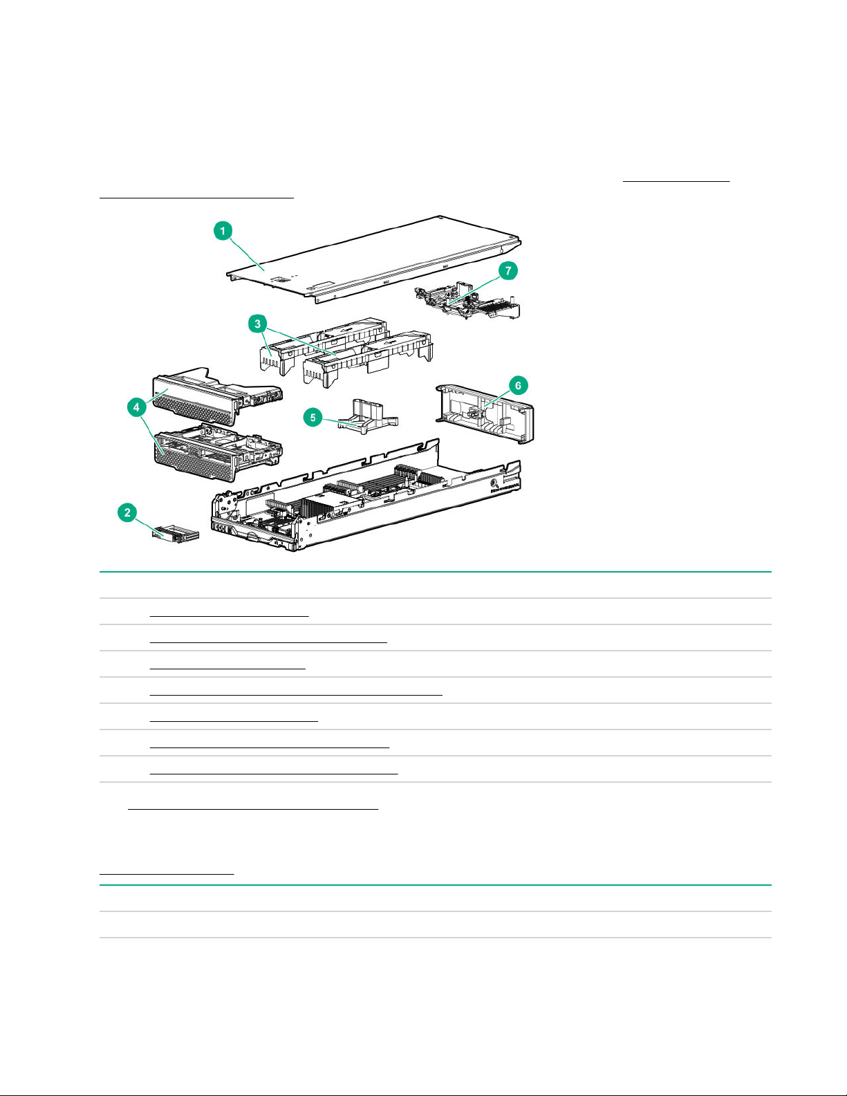
Mechanical components
Hewlett Packard Enterprise continually improves and changes product parts. See the
Enterprise PartSurfer website for complete and current supported parts information.
Hewlett Packard
Item Description
1 Access panel spare part
2 SFF HDD blank assembly spare part
3 DIMM baffle spare parts
4 Front panel/drive cage assembly spare parts
5 Heatsink blank spare part
6 Compute module end cap spare part
7 Mezzanine frame assembly spare part
See Removal and replacement procedures for more information.
Access panel spare part
Customer self repair on page 17: mandatory
Description Spare part number
Access panel 873077-001
6 Illustrated parts catalog
Page 7

SFF HDD blank assembly spare part
Customer self repair: mandatory
Description Part number
SFF HDD blank assembly 670033-001
DIMM baffle spare parts
Customer self repair on page 17: mandatory
Description Spare part number
DIMM baffles 873078-001
Front panel/drive cage assembly spare parts
Customer self repair on page 17: mandatory
Description Spare part number
Front panel/drive cage assembly, standard 873079-001
Front panel/drive cage assembly, no drives 830892-001
HPE Synergy 480 Gen10 pull tab 873074-001
Rear heatsink blank spare part
Customer self repair on page 17: mandatory
Description Spare part number
Rear heatsink blank 873080-001
Compute module end cap spare part
Customer self repair on page 17: mandatory
Description Spare part number
Compute module end cap 813579-001
Mezzanine assembly spare part
Customer self repair on page 17: mandatory
Description Spare part number
Mezzanine assembly 801369-001
System components
Hewlett Packard Enterprise continually improves and changes product parts. See the Hewlett Packard
Enterprise PartSurfer website for complete and current supported parts information.
SFF HDD blank assembly spare part 7
Page 8
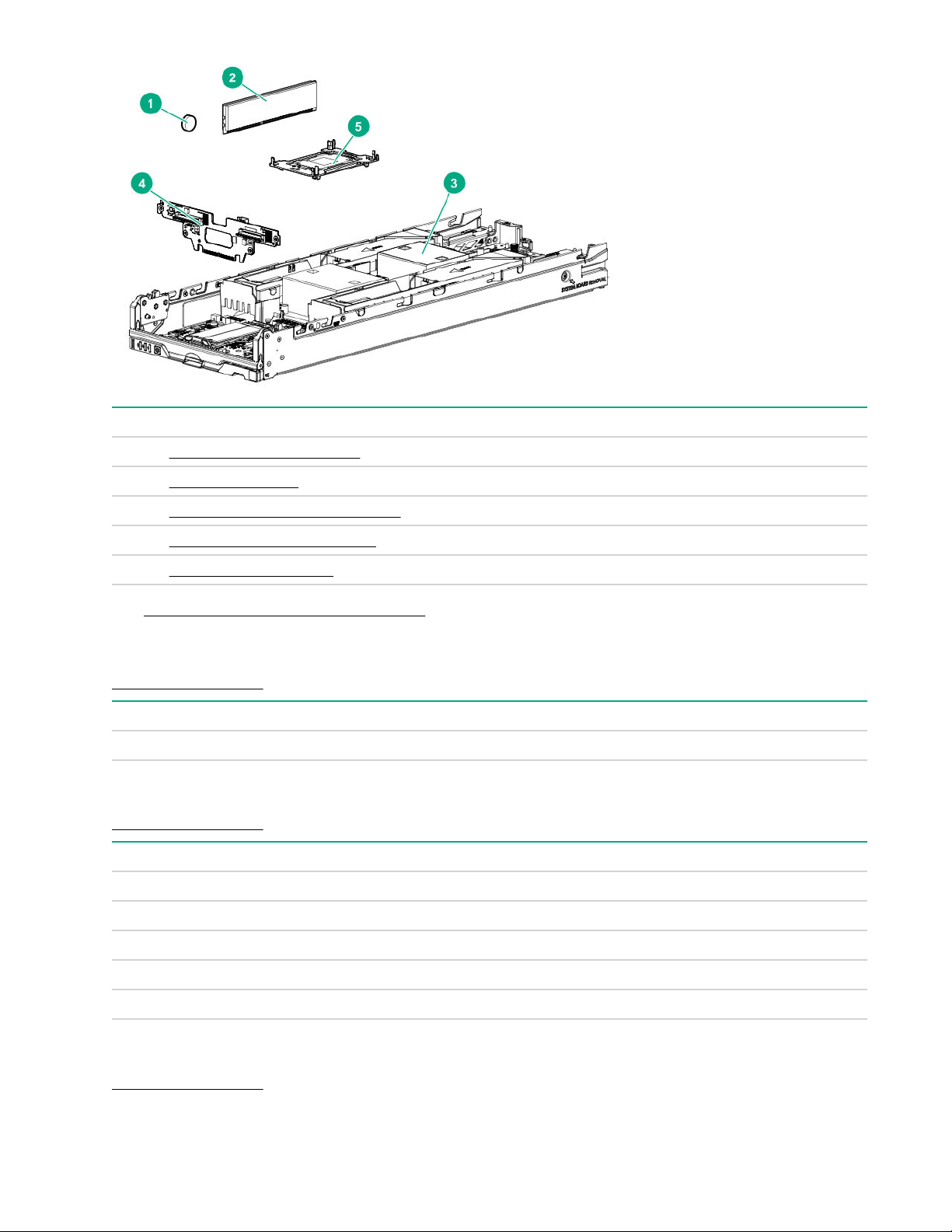
Item Description
1 System battery spare part
2 DIMM spare parts
3 Processor heatsink spare parts
4 Drive backplane spare parts
5 Processor spare parts
See Removal and replacement procedures for more information.
System battery spare part
Customer self repair on page 17: optional
Description Spare part number
System battery 234556-001
DIMM spare parts
Customer self repair on page 17: mandatory
Description Spare part number
8-GB, 1Gx8, PC4-2666V-R 850879-001
16-GB, 2Gx4, PC4-2666V-R 850880-001
16-GB, 1Gx8, PC4-2666V-R 868846-001
32-GB, 2Gx4, PC4-2666V-L 850881-001
64-GB, 2Gx4, PC4-2666V-L 850882-001
HPE 16GB NVDIMM spare part
Customer self repair on page 17: mandatory
8 System battery spare part
Page 9

Description Spare part number
NVDIMM 16GB 1Rx4 NN4-2666V-R 874540-001
Processor heatsink spare parts
Customer self repair on page 17: no
Description Spare part number
Rear processor heatsink (processors 3 and 4) 873081-001
Front processor heatsink (processors 1 and 2) 873082-001
System board spare part
Customer self repair on page 17: optional
Description Spare part number
System board 870841-001
Drive backplane spare parts
Customer self repair on page 17: mandatory
Description Spare part number
Standard drive backplane 873075-001
Premium drive backplane 873076-001
Processor spare parts
Customer self repair on page 17: no
All Intel Xeon processors in this HPE ProLiant server must have the same cache size, speed, number of
cores, and rated maximum power consumption.
Description Spare part number
8180M SKL Xeon-P 28c 205W 878089-001
8176M SKL Xeon-P 28c 165W 878088-001
8170M SKL Xeon-P 26c 165W 878087-001
8160M SKL Xeon-P 24c 150W 878086-001
6142M SKL Xeon-G 16c 150W 878085-001
6140M SKL Xeon-G 18c 140W 878084-001
6134M SKL Xeon-G 8c 130W 878083-001
CPU 5115 SKL Xeon-G 10c 85W 878082-001
Xeon-P 8158 12c 150W 875733-001
Xeon-P 8156 4c 105W 875732-001
Table Continued
Processor heatsink spare parts 9
Page 10

Description Spare part number
Xeon-P 8180 28c 205W 875731-001
Xeon-P 8168 24c 205W 875730-001
Xeon-P 8164 26c 150W 875729-001
Xeon-P 8153 16c 120W 875728-001
Xeon-G 6154 18c 200W 875727-001
Xeon-G 6146 12c 165W 875726-001
Xeon-G 6144 8c 150W 875725-001
Xeon-G 6136 12c 875724-001
Xeon-G 6134 8c 130W 875723-001
Xeon-G 6132 14c 133W 875722-001
Xeon-G 6128 6c 115W 875721-001
Xeon-G 6126 12c 125W 875720-001
Xeon-G 5122 4c 105W 875719-001
Xeon-G 51xx 14c 105W 875718-001
Xeon-G 51xx 12c 105W 875717-001
Xeon-S 41xx 12c 85W 875716-001
Xeon-S 41xx 4c 85W 875714-001
Xeon-S 41xx 10c 85W 875713-001
Xeon-S 41xx 8c 85W 875712-001
Xeon-S 41xx 8c 85W 875711-001
Xeon-B 31xx 8c 85W 875710-001
Xeon-B 31xx 6c 85W 875709-001
Xeon-G 6130 16c 2.1G 125W 874736-001
Xeon-G 6138 20c 2.0G 125W 874735-001
Xeon-G 6140 18c 2.3G 140W 874734-001
Xeon-G 6142 16c 2.6G 150W 874733-001
Xeon-G 6148 20c 2.4G 150W 874732-001
Xeon-G 6150 18c 2.7G 165W 874731-001
Xeon-G 6152 22c 2.1G 140W 874730-001
Xeon-P 8160 24C 2.1G 150W 874729-001
Xeon-P 8170 26c 2.1G 165W 874728-001
Xeon-P 8176 28c 2.1G 165W 874727-001
10 Illustrated parts catalog
Page 11
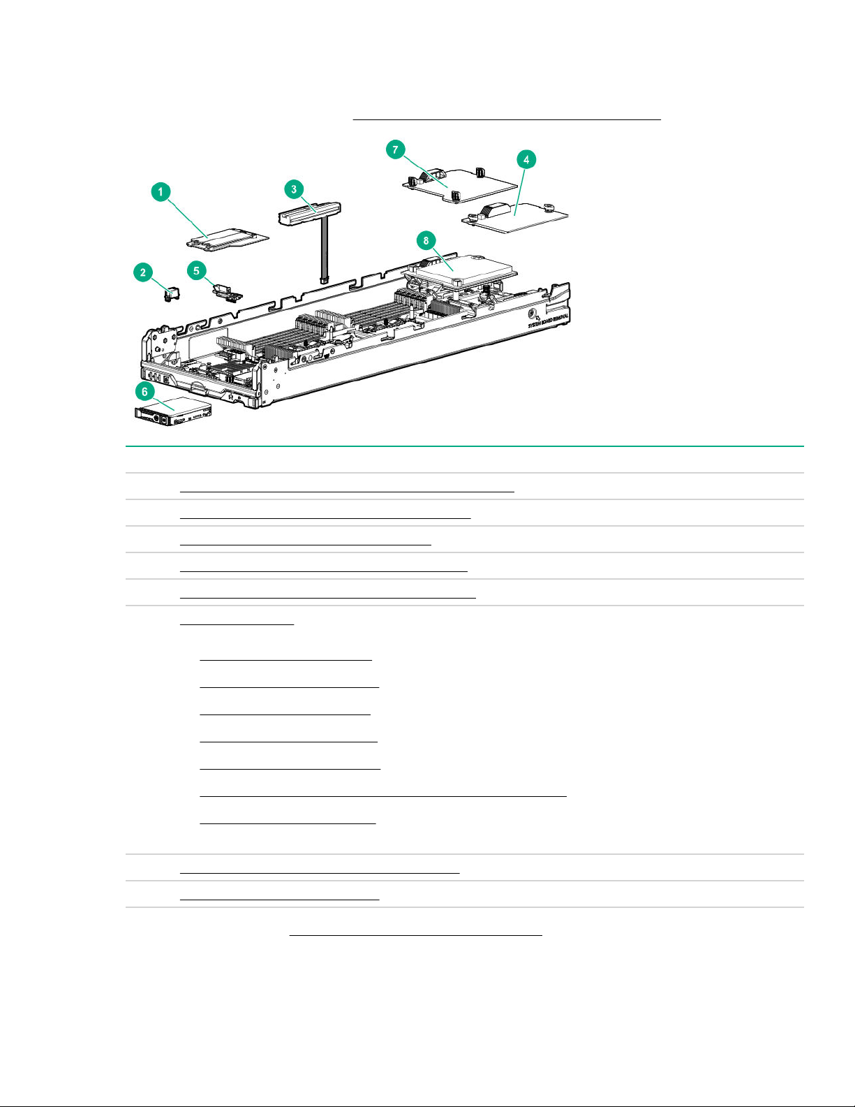
Compute module options
Hewlett Packard Enterprise continually improves and changes product parts. For complete and current
supported parts information, see the Hewlett Packard Enterprise PartSurfer website.
Item Description
1 M.2 SSD flash drive and adapter board spare parts
2 HPE Trusted Platform Module 2.0 spare part
3 HPE Smart Storage Battery spare part
4 Mezzanine option card (Type C) spare parts
5 HPE Synergy Internal SATA board spare part
6 Drive spare parts
• SFF SAS HDD spare parts
• SFF SATA HDD spare parts
• SFF SAS SSD spare parts
• SFF SATA SSD spare parts
• SFF NVMe SSD spare parts
• Dual Flash Adapter and SFF SATA uFF SSD spare parts
• M.2 flash drive spare parts
7 Mezzanine option card (Type D) spare part
8 Storage controller spare parts
For more information, see Removal and replacement procedures.
M.2 SSD adapter board spare part
Customer self repair: optional
Compute module options 11
Page 12

Description Spare part number
M.2 SSD adapter board kit 873086-001
M.2 flash drive spare parts
Customer self repair on page 17: mandatory
Description Spare part number
480 GB SATA M.2 2280 RI DS 875836-001
150 GB SATA M.2 2280 RI DS 875835-001
120 GB 6G SATA RI 781565-001
340 GB SATA RI 781566-001
HPE Trusted Platform Module 2.0 spare part
Customer self repair on page 17: no
Description Spare part number
HPE Trusted Platform Module 2.0 Gen 10 kit, TAA 872159-001
HPE Smart Storage Battery spare part
Customer self repair on page 17: mandatory
Description Spare part number
HPE Smart Storage Battery with cable, 96W 878644-001
Mezzanine option spare parts
Customer self repair: mandatory
Description Spare part number
HPE Synergy 2820C 10Gb CNA 815670-001
HPE Synergy 3820C 10/20Gb CNA 782833-001
HPE Synergy 3830C 16G FC Host Bus Adapter 782829-001
HPE Synergy 480 AMD FirePro S7100X 849147-001*
HPE Synergy 480 NVIDIA Quadro M3000SE 869002-001*
HPE Synergy 480 NVIDIA Tesla M6 808409-001*
* This spare part number is for the graphics option card only. Spare part numbers for heatsink and adapter
board are shown in Mechanical components. You must order the thermal grease kit (PN 874039-001) with
the graphics option card spare part.
For more information, see Removal and replacement procedures.
HPE Synergy Internal SATA board spare part
Customer self repair: mandatory
12 M.2 flash drive spare parts
Page 13
Description Spare part number
HPE Synergy Internal SATA board 873085-001
Drive spare parts
SFF SAS HDD spare parts
Customer self repair on page 17: mandatory
Description Spare part number
600 GB SAS 15,000-rpm, SFF SC DS HDD 870794-001
900 GB SAS 15,000-rpm, SFF SC DS HDD 870795-001
600 GB SAS 15,000-rpm, SFF SC 512e DS HDD 870797-001
900 GB SAS 15,000-rpm, SFF SC 512e DS HDD 870798-001
300 GB SAS 10,000-rpm, SFF SC DS HDD 872735-001
600 GB SAS 10,000-rpm, SFF SC DS HDD 872736-001
1.2 TB SAS 10,000-rpm, SFF SC DS HDD 872737-001
1.8 TB SAS 10,000-rpm, SFF SC 512e DS HDD 872738-001
600 GB SAS 10,000-rpm, SFF SC HDD 781577-001
1.2 TB SAS 10,000-rpm, SFF SC HDD 781578-001
300 GB SAS 10,000-rpm, SFF SC HDD 785410-001
900 GB SAS 10,000-rpm, SFF SC HDD 785411-001
1.8 TB SAS 10,000-rpm, SFF SC 512e HDD 791055-001
1 TB SAS 7.2K SFF SC 512e DS HDD 765872-001
2 TB SAS 7.2K SFF SC 512e DS HDD 765873-001
1 TB SAS 7.2K SFF SC DS HDD 832984-001
HDD BLANK SFF 670033-001
Drive spare parts 13
Page 14
SFF SATA HDD spare parts
Customer self repair on page 17: mandatory
Description Spare part number
1 TB SATA 7,200-rpm, SFF SC 512e DS HDD 765868-001
2 TB SATA 7,200-rpm, SFF SC 512e DS HDD 765869-001
1 TB SATA 7,200-rpm, SFF SC DS HDD 656108-001
SFF SAS SSD spare parts
Customer self repair on page 17: mandatory
Description Spare part number
3.2TB 12G, MU SC 872511-001
1.6TB 12G, MU SC 872509-001
800GB 12G, MU SC 872506-001
400GB 12G, MU SC 872505-001
3.84TB 12G, RI SC 872434-001
1.92TB 12G, RI SC 872433-001
960GB 12G, RI SC 872432-001
SFF SATA SSD spare parts
Customer self repair on page 17: mandatory
14 SFF SATA HDD spare parts
Page 15
Description Spare part number
400 GB SATA, 6G, WI, SFF SC DS SSD 872512-001
800 GB SATA, 6G, WI, SFF SC DS SSD 872514-001
1.6 TB SATA,, 6G, WI, SFF SC DS SSD 872516-001
240 GB SATA, 6G, RI, SFF SC DS SSD 868924-001
480 GB SATA, 6G, RI, SFF SC DS SSD 868936-001
960 GB SATA, 6G, RI, SFF SC DS SSD 868928-001
1.92 TB SATA, 6G, RI, SFF SC DS SSD 868930-001
3.84 TB SATA, 6G, RI, SFF SC DS SSD 868932-001
480 GB SATA, 6G, MU, SFF SC DS SSD 872518-001
960 GB SATA, 6G, MU, SFF SC DS SSD 872520-001
1.92 TB SATA, 6G, MU, SFF SC DS SSD 872522-001
SFF NVMe SSD spare parts
Customer self repair on page 17: mandatory
Description Spare part number
400 GB NVMe x4 WI SFF SC SSD 765059-001
800 GB NVMe x4 WI SFF SCN SSD 765060-001
1.6 TB NVMe x4 WI SFF SCN SSD 765061-001
2 TB NVMe x4 WI SFF SCN SSD 765062-001
Dual Flash Adapter and SFF SATA uFF SSD spare parts
Customer self repair on page 17: mandatory
SFF NVMe SSD spare parts 15
Page 16

Description Spare part number
Dual flash adapter spare 830452-001
uFF SSD 120 GB 831995-001
uFF SSD 340 GB 830453-001
USB and microSD option spare parts
Customer self repair on page 17: mandatory
Description Spare part number
HPE Dual 8GB microSD EM USB device 799057-001
8-GB USB flash media key 743503-001
8-GB micro SDHC flash media card 738576-001
Storage controller spare parts
Customer self repair on page 17: mandatory
Description Spare part number
HPE Smart Array P204i-c Controller 836274-001
HPE Smart Array P416ie-m Controller 873947-001
HPE Smart Array P208i-c Controller 836276-001
HPE Synergy 3530C 16G FC HBA 782830-001
HPE Synergy 3830C 16G GC HBA 782829-001
HPE Synergy P552D x16 Smart Array Controller 836275-001
16 USB and microSD option spare parts
Page 17

Customer self repair
Hewlett Packard Enterprise products are designed with many Customer Self Repair (CSR) parts to minimize
repair time and allow for greater flexibility in performing defective parts replacement. If during the diagnosis
period Hewlett Packard Enterprise (or Hewlett Packard Enterprise service providers or service partners)
identifies that the repair can be accomplished by the use of a CSR part, Hewlett Packard Enterprise will ship
that part directly to you for replacement. There are two categories of CSR parts:
• Mandatory—Parts for which customer self repair is mandatory. If you request Hewlett Packard Enterprise
to replace these parts, you will be charged for the travel and labor costs of this service.
• Optional—Parts for which customer self repair is optional. These parts are also designed for customer
self repair. If, however, you require that Hewlett Packard Enterprise replace them for you, there may or
may not be additional charges, depending on the type of warranty service designated for your product.
NOTE: Some Hewlett Packard Enterprise parts are not designed for customer self repair. In order to satisfy
the customer warranty, Hewlett Packard Enterprise requires that an authorized service provider replace the
part. These parts are identified as "No" in the Illustrated Parts Catalog.
Based on availability and where geography permits, CSR parts will be shipped for next business day delivery.
Same day or four-hour delivery may be offered at an additional charge where geography permits. If
assistance is required, you can call the Hewlett Packard Enterprise Support Center and a technician will help
you over the telephone. Hewlett Packard Enterprise specifies in the materials shipped with a replacement
CSR part whether a defective part must be returned to Hewlett Packard Enterprise. In cases where it is
required to return the defective part to Hewlett Packard Enterprise, you must ship the defective part back to
Hewlett Packard Enterprise within a defined period of time, normally five (5) business days. The defective part
must be returned with the associated documentation in the provided shipping material. Failure to return the
defective part may result in Hewlett Packard Enterprise billing you for the replacement. With a customer self
repair, Hewlett Packard Enterprise will pay all shipping and part return costs and determine the courier/carrier
to be used.
For more information about the Hewlett Packard Enterprise CSR program, contact your local service provider.
For the North American program, go to the Hewlett Packard Enterprise CSR website.
Parts only warranty service
Your Hewlett Packard Enterprise Limited Warranty may include a parts only warranty service. Under the terms
of parts only warranty service, Hewlett Packard Enterprise will provide replacement parts free of charge.
For parts only warranty service, CSR part replacement is mandatory. If you request Hewlett Packard
Enterprise to replace these parts, you will be charged for the travel and labor costs of this service.
Réparation par le client (CSR)
Les produits Hewlett Packard Enterprise comportent de nombreuses pièces CSR (Customer Self Repair =
réparation par le client) afin de minimiser les délais de réparation et faciliter le remplacement des pièces
défectueuses. Si pendant la période de diagnostic, Hewlett Packard Enterprise (ou ses partenaires ou
mainteneurs agréés) détermine que la réparation peut être effectuée à l'aide d'une pièce CSR, Hewlett
Packard Enterprise vous l'envoie directement. Il existe deux catégories de pièces CSR :
• Obligatoire—Pièces pour lesquelles la réparation par le client est obligatoire. Si vous demandez à
Hewlett Packard Enterprise de remplacer ces pièces, les coûts de déplacement et main d'œuvre du
service vous seront facturés.
• Facultatif—Pièces pour lesquelles la réparation par le client est facultative. Ces pièces sont également
conçues pour permettre au client d'effectuer lui-même la réparation. Toutefois, si vous demandez à
Customer self repair 17
Page 18

Hewlett Packard Enterprise de remplacer ces pièces, l'intervention peut ou non vous être facturée, selon
le type de garantie applicable à votre produit.
REMARQUE: Certaines pièces Hewlett Packard Enterprise ne sont pas conçues pour permettre au client
d'effectuer lui-même la réparation. Pour que la garantie puisse s'appliquer, Hewlett Packard Enterprise exige
que le remplacement de la pièce soit effectué par un Mainteneur Agréé. Ces pièces sont identifiées par la
mention "Non" dans le Catalogue illustré.
Les pièces CSR sont livrées le jour ouvré suivant, dans la limite des stocks disponibles et selon votre
situation géographique. Si votre situation géographique le permet et que vous demandez une livraison le jour
même ou dans les 4 heures, celle-ci vous sera facturée. Pour toute assistance, appelez le Centre
d’assistance Hewlett Packard Enterprise pour qu’un technicien vous aide au téléphone Dans les documents
envoyés avec la pièce de rechange CSR, Hewlett Packard Enterprise précise s'il est nécessaire de lui
retourner la pièce défectueuse. Si c'est le cas, vous devez le faire dans le délai indiqué, généralement cinq
(5) jours ouvrés. La pièce et sa documentation doivent être retournées dans l'emballage fourni. Si vous ne
retournez pas la pièce défectueuse, Hewlett Packard Enterprise se réserve le droit de vous facturer les coûts
de remplacement. Dans le cas d'une pièce CSR, Hewlett Packard Enterprise supporte l'ensemble des frais
d'expédition et de retour, et détermine la société de courses ou le transporteur à utiliser.
Pour plus d'informations sur le programme CSR de Hewlett Packard Enterprise, contactez votre Mainteneur
Agrée local. Pour plus d'informations sur ce programme en Amérique du Nord, consultez le site Web Hewlett
Packard Enterprise.
Service de garantie "pièces seules"
Votre garantie limitée Hewlett Packard Enterprise peut inclure un service de garantie "pièces seules". Dans
ce cas, les pièces de rechange fournies par Hewlett Packard Enterprise ne sont pas facturées.
Dans le cadre de ce service, la réparation des pièces CSR par le client est obligatoire. Si vous demandez à
Hewlett Packard Enterprise de remplacer ces pièces, les coûts de déplacement et main d'œuvre du service
vous seront facturés.
Riparazione da parte del cliente
Per abbreviare i tempi di riparazione e garantire una maggiore flessibilità nella sostituzione di parti difettose, i
prodotti Hewlett Packard Enterprise sono realizzati con numerosi componenti che possono essere riparati
direttamente dal cliente (CSR, Customer Self Repair). Se in fase di diagnostica Hewlett Packard Enterprise (o
un centro di servizi o di assistenza Hewlett Packard Enterprise) identifica il guasto come riparabile mediante
un ricambio CSR, Hewlett Packard Enterprise lo spedirà direttamente al cliente per la sostituzione. Vi sono
due categorie di parti CSR:
• Obbligatorie—Parti che devono essere necessariamente riparate dal cliente. Se il cliente ne affida la
riparazione ad Hewlett Packard Enterprise, deve sostenere le spese di spedizione e di manodopera per il
servizio.
• Opzionali—Parti la cui riparazione da parte del cliente è facoltativa. Si tratta comunque di componenti
progettati per questo scopo. Se tuttavia il cliente ne richiede la sostituzione ad Hewlett Packard Enterprise,
potrebbe dover sostenere spese addizionali a seconda del tipo di garanzia previsto per il prodotto.
NOTA: alcuni componenti Hewlett Packard Enterprise non sono progettati per la riparazione da parte del
cliente. Per rispettare la garanzia, Hewlett Packard Enterprise richiede che queste parti siano sostituite da un
centro di assistenza autorizzato. Tali parti sono identificate da un "No" nel Catalogo illustrato dei componenti.
In base alla disponibilità e alla località geografica, le parti CSR vengono spedite con consegna entro il giorno
lavorativo seguente. La consegna nel giorno stesso o entro quattro ore è offerta con un supplemento di costo
solo in alcune zone. In caso di necessità si può richiedere l'assistenza telefonica di un addetto del centro di
supporto tecnico Hewlett Packard Enterprise. Nel materiale fornito con una parte di ricambio CSR, Hewlett
Packard Enterprise specifica se il cliente deve restituire dei component. Qualora sia richiesta la resa ad
Hewlett Packard Enterprise del componente difettoso, lo si deve spedire ad Hewlett Packard Enterprise entro
un determinato periodo di tempo, generalmente cinque (5) giorni lavorativi. Il componente difettoso deve
18 Customer self repair
Page 19

essere restituito con la documentazione associata nell'imballo di spedizione fornito. La mancata restituzione
del componente può comportare la fatturazione del ricambio da parte di Hewlett Packard Enterprise. Nel caso
di riparazione da parte del cliente, Hewlett Packard Enterprise sostiene tutte le spese di spedizione e resa e
sceglie il corriere/vettore da utilizzare.
Per ulteriori informazioni sul programma CSR di Hewlett Packard Enterprise, contattare il centro di assistenza
di zona. Per il programma in Nord America fare riferimento al sito Web.
Servizio di garanzia per i soli componenti
La garanzia limitata Hewlett Packard Enterprise può includere un servizio di garanzia per i soli componenti.
Nei termini di garanzia del servizio per i soli componenti, Hewlett Packard Enterprise fornirà gratuitamente le
parti di ricambio.
Per il servizio di garanzia per i soli componenti è obbligatoria la formula CSR che prevede la riparazione da
parte del cliente. Se il cliente invece richiede la sostituzione ad Hewlett Packard Enterprise dovrà sostenere le
spese di spedizione e di manodopera per il servizio.
Customer Self Repair
Hewlett Packard Enterprise Produkte enthalten viele CSR-Teile (Customer Self Repair), um Reparaturzeiten
zu minimieren und höhere Flexibilität beim Austausch defekter Bauteile zu ermöglichen. Wenn Hewlett
Packard Enterprise (oder ein Hewlett Packard Enterprise Servicepartner) bei der Diagnose feststellt, dass das
Produkt mithilfe eines CSR-Teils repariert werden kann, sendet Ihnen Hewlett Packard Enterprise dieses
Bauteil zum Austausch direkt zu. CSR-Teile werden in zwei Kategorien unterteilt:
• Zwingend—Teile, für die das Customer Self Repair-Verfahren zwingend vorgegeben ist. Wenn Sie den
Austausch dieser Teile von Hewlett Packard Enterprise vornehmen lassen, werden Ihnen die Anfahrt- und
Arbeitskosten für diesen Service berechnet.
• Optional—Teile, für die das Customer Self Repair-Verfahren optional ist. Diese Teile sind auch für
Customer Self Repair ausgelegt. Wenn Sie jedoch den Austausch dieser Teile von Hewlett Packard
Enterprise vornehmen lassen möchten, können bei diesem Service je nach den für Ihr Produkt
vorgesehenen Garantiebedingungen zusätzliche Kosten anfallen.
HINWEIS: Einige Hewlett Packard Enterprise Teile sind nicht für Customer Self Repair ausgelegt. Um den
Garantieanspruch des Kunden zu erfüllen, muss das Teil von einem Hewlett Packard Enterprise
Servicepartner ersetzt werden. Im illustrierten Teilekatalog sind diese Teile mit „No“ bzw.
„Nein“ gekennzeichnet.
CSR-Teile werden abhängig von der Verfügbarkeit und vom Lieferziel am folgenden Geschäftstag geliefert.
Für bestimmte Standorte ist eine Lieferung am selben Tag oder innerhalb von vier Stunden gegen einen
Aufpreis verfügbar. Wenn Sie Hilfe benötigen, können Sie das Hewlett Packard Enterprise Support Center
anrufen und sich von einem Mitarbeiter per Telefon helfen lassen. Den Materialien von Hewlett Packard
Enterprise, die mit einem CSR-Ersatzteil geliefert werden, können Sie entnehmen, ob das defekte Teil an
Hewlett Packard Enterprise zurückgeschickt werden muss. Wenn es erforderlich ist, das defekte Teil an
Hewlett Packard Enterprise zurückzuschicken, müssen Sie dies innerhalb eines vorgegebenen Zeitraums tun,
in der Regel innerhalb von fünf (5) Geschäftstagen. Das defekte Teil muss mit der zugehörigen
Dokumentation in der Verpackung zurückgeschickt werden, die im Lieferumfang enthalten ist. Wenn Sie das
defekte Teil nicht zurückschicken, kann Hewlett Packard Enterprise Ihnen das Ersatzteil in Rechnung stellen.
Im Falle von Customer Self Repair kommt Hewlett Packard Enterprise für alle Kosten für die Lieferung und
Rücksendung auf und bestimmt den Kurier-/Frachtdienst.
Weitere Informationen über das Hewlett Packard Enterprise Customer Self Repair Programm erhalten Sie
von Ihrem Servicepartner vor Ort. Informationen über das CSR-Programm in Nordamerika finden Sie auf der
Hewlett Packard Enterprise Website unter.
Customer self repair 19
Page 20

Parts-only Warranty Service (Garantieservice ausschließlich für Teile)
Ihre Hewlett Packard Enterprise Garantie umfasst möglicherweise einen Parts-only Warranty Service
(Garantieservice ausschließlich für Teile). Gemäß den Bestimmungen des Parts-only Warranty Service stellt
Hewlett Packard Enterprise Ersatzteile kostenlos zur Verfügung.
Für den Parts-only Warranty Service ist das CSR-Verfahren zwingend vorgegeben. Wenn Sie den Austausch
dieser Teile von Hewlett Packard Enterprise vornehmen lassen, werden Ihnen die Anfahrt- und Arbeitskosten
für diesen Service berechnet.
Reparaciones del propio cliente
Los productos de Hewlett Packard Enterprise incluyen muchos componentes que el propio usuario puede
reemplazar (Customer Self Repair, CSR) para minimizar el tiempo de reparación y ofrecer una mayor
flexibilidad a la hora de realizar sustituciones de componentes defectuosos. Si, durante la fase de
diagnóstico, Hewlett Packard Enterprise (o los proveedores o socios de servicio de Hewlett Packard
Enterprise) identifica que una reparación puede llevarse a cabo mediante el uso de un componente CSR,
Hewlett Packard Enterprise le enviará dicho componente directamente para que realice su sustitución. Los
componentes CSR se clasifican en dos categorías:
• Obligatorio—Componentes cuya reparación por parte del usuario es obligatoria. Si solicita a Hewlett
Packard Enterprise que realice la sustitución de estos componentes, tendrá que hacerse cargo de los
gastos de desplazamiento y de mano de obra de dicho servicio.
• Opcional—Componentes cuya reparación por parte del usuario es opcional. Estos componentes también
están diseñados para que puedan ser reparados por el usuario. Sin embargo, si precisa que Hewlett
Packard Enterprise realice su sustitución, puede o no conllevar costes adicionales, dependiendo del tipo
de servicio de garantía correspondiente al producto.
NOTA: Algunos componentes de Hewlett Packard Enterprise no están diseñados para que puedan ser
reparados por el usuario. Para que el usuario haga valer su garantía, Hewlett Packard Enterprise pone como
condición que un proveedor de servicios autorizado realice la sustitución de estos componentes. Dichos
componentes se identifican con la palabra "No" en el catálogo ilustrado de componentes.
Según la disponibilidad y la situación geográfica, los componentes CSR se enviarán para que lleguen a su
destino al siguiente día laborable. Si la situación geográfica lo permite, se puede solicitar la entrega en el
mismo día o en cuatro horas con un coste adicional. Si precisa asistencia técnica, puede llamar al Centro de
asistencia técnica de Hewlett Packard Enterprise y recibirá ayuda telefónica por parte de un técnico. Con el
envío de materiales para la sustitución de componentes CSR, Hewlett Packard Enterprise especificará si los
componentes defectuosos deberán devolverse a Hewlett Packard Enterprise. En aquellos casos en los que
sea necesario devolver algún componente a Hewlett Packard Enterprise, deberá hacerlo en el periodo de
tiempo especificado, normalmente cinco días laborables. Los componentes defectuosos deberán devolverse
con toda la documentación relacionada y con el embalaje de envío. Si no enviara el componente defectuoso
requerido, Hewlett Packard Enterprise podrá cobrarle por el de sustitución. En el caso de todas sustituciones
que lleve a cabo el cliente, Hewlett Packard Enterprise se hará cargo de todos los gastos de envío y
devolución de componentes y escogerá la empresa de transporte que se utilice para dicho servicio.
Para obtener más información acerca del programa de Reparaciones del propio cliente de Hewlett Packard
Enterprise, póngase en contacto con su proveedor de servicios local. Si está interesado en el programa para
Norteamérica, visite la página web de Hewlett Packard Enterprise CSR.
Servicio de garantía exclusivo de componentes
La garantía limitada de Hewlett Packard Enterprise puede que incluya un servicio de garantía exclusivo de
componentes. Según las condiciones de este servicio exclusivo de componentes, Hewlett Packard Enterprise
le facilitará los componentes de repuesto sin cargo adicional alguno.
Para este servicio de garantía exclusivo de componentes, es obligatoria la sustitución de componentes por
parte del usuario (CSR). Si solicita a Hewlett Packard Enterprise que realice la sustitución de estos
20 Customer self repair
Page 21

componentes, tendrá que hacerse cargo de los gastos de desplazamiento y de mano de obra de dicho
servicio.
Customer Self Repair
Veel onderdelen in Hewlett Packard Enterprise producten zijn door de klant zelf te repareren, waardoor de
reparatieduur tot een minimum beperkt kan blijven en de flexibiliteit in het vervangen van defecte onderdelen
groter is. Deze onderdelen worden CSR-onderdelen (Customer Self Repair) genoemd. Als Hewlett Packard
Enterprise (of een Hewlett Packard Enterprise Service Partner) bij de diagnose vaststelt dat de reparatie kan
worden uitgevoerd met een CSR-onderdeel, verzendt Hewlett Packard Enterprise dat onderdeel rechtstreeks
naar u, zodat u het defecte onderdeel daarmee kunt vervangen. Er zijn twee categorieën CSR-onderdelen:
• Verplicht—Onderdelen waarvoor reparatie door de klant verplicht is. Als u Hewlett Packard Enterprise
verzoekt deze onderdelen voor u te vervangen, worden u voor deze service reiskosten en arbeidsloon in
rekening gebracht.
• Optioneel—Onderdelen waarvoor reparatie door de klant optioneel is. Ook deze onderdelen zijn
ontworpen voor reparatie door de klant. Als u echter Hewlett Packard Enterprise verzoekt deze
onderdelen voor u te vervangen, kunnen daarvoor extra kosten in rekening worden gebracht, afhankelijk
van het type garantieservice voor het product.
OPMERKING: Sommige Hewlett Packard Enterprise onderdelen zijn niet ontwikkeld voor reparatie door de
klant. In verband met de garantievoorwaarden moet het onderdeel door een geautoriseerde Service Partner
worden vervangen. Deze onderdelen worden in de geïllustreerde onderdelencatalogus aangemerkt met
"Nee".
Afhankelijk van de leverbaarheid en de locatie worden CSR-onderdelen verzonden voor levering op de
eerstvolgende werkdag. Levering op dezelfde dag of binnen vier uur kan tegen meerkosten worden
aangeboden, indien dit mogelijk is gezien de locatie. Indien assistentie is gewenst, belt u het Hewlett Packard
Enterprise Support Center om via de telefoon ondersteuning van een technicus te ontvangen. Hewlett
Packard Enterprise vermeldt in de documentatie bij het vervangende CSR-onderdeel of het defecte onderdeel
aan Hewlett Packard Enterprise moet worden geretourneerd. Als het defecte onderdeel aan Hewlett Packard
Enterprise moet worden teruggezonden, moet u het defecte onderdeel binnen een bepaalde periode,
gewoonlijk vijf (5) werkdagen, retourneren aan Hewlett Packard Enterprise. Het defecte onderdeel moet met
de bijbehorende documentatie worden geretourneerd in het meegeleverde verpakkingsmateriaal. Als u het
defecte onderdeel niet terugzendt, kan Hewlett Packard Enterprise u voor het vervangende onderdeel kosten
in rekening brengen. Bij reparatie door de klant betaalt Hewlett Packard Enterprise alle verzendkosten voor
het vervangende en geretourneerde onderdeel en kiest Hewlett Packard Enterprise zelf welke koerier/
transportonderneming hiervoor wordt gebruikt.
Neem contact op met een Service Partner voor meer informatie over het Customer Self Repair programma
van Hewlett Packard Enterprise. Informatie over Service Partners vindt u op de Hewlett Packard Enterprise
website.
Garantieservice "Parts Only"
Het is mogelijk dat de Hewlett Packard Enterprise garantie alleen de garantieservice "Parts Only" omvat.
Volgens de bepalingen van de Parts Only garantieservice zal Hewlett Packard Enterprise kosteloos
vervangende onderdelen ter beschikking stellen.
Voor de Parts Only garantieservice is vervanging door CSR-onderdelen verplicht. Als u Hewlett Packard
Enterprise verzoekt deze onderdelen voor u te vervangen, worden u voor deze service reiskosten en
arbeidsloon in rekening gebracht
Reparo feito pelo cliente
Os produtos da Hewlett Packard Enterprise são projetados com muitas peças para reparo feito pelo cliente
(CSR) de modo a minimizar o tempo de reparo e permitir maior flexibilidade na substituição de peças com
defeito. Se, durante o período de diagnóstico, a Hewlett Packard Enterprise (ou fornecedores/parceiros da
Customer self repair 21
Page 22

Hewlett Packard Enterprise) concluir que o reparo pode ser efetuado pelo uso de uma peça CSR, a Hewlett
Packard Enterprise enviará a peça diretamente ao cliente. Há duas categorias de peças CSR:
• Obrigatória—Peças cujo reparo feito pelo cliente é obrigatório. Se desejar que a Hewlett Packard
Enterprise substitua essas peças, serão cobradas as despesas de transporte e mão-de-obra do serviço.
• Opcional—Peças cujo reparo feito pelo cliente é opcional. Essas peças também são projetadas para o
reparo feito pelo cliente. No entanto, se desejar que a Hewlett Packard Enterprise as substitua, pode
haver ou não a cobrança de taxa adicional, dependendo do tipo de serviço de garantia destinado ao
produto.
OBSERVAÇÃO: Algumas peças da Hewlett Packard Enterprise não são projetadas para o reparo feito pelo
cliente. A fim de cumprir a garantia do cliente, a Hewlett Packard Enterprise exige que um técnico autorizado
substitua a peça. Essas peças estão identificadas com a marca "No" (Não), no catálogo de peças ilustrado.
Conforme a disponibilidade e o local geográfico, as peças CSR serão enviadas no primeiro dia útil após o
pedido. Onde as condições geográficas permitirem, a entrega no mesmo dia ou em quatro horas pode ser
feita mediante uma taxa adicional. Se precisar de auxílio, entre em contato com o Centro de suporte técnico
da Hewlett Packard Enterprise para que um técnico o ajude por telefone. A Hewlett Packard Enterprise
especifica nos materiais fornecidos com a peça CSR de reposição se a peça com defeito deve ser devolvida
à Hewlett Packard Enterprise. Nos casos em que isso for necessário, é preciso enviar a peça com defeito à
Hewlett Packard Enterprise, você deverá enviar a peça com defeito de volta para a Hewlett Packard
Enterprise dentro do período de tempo definido, normalmente em 5 (cinco) dias úteis. A peça com defeito
deve ser enviada com a documentação correspondente no material de transporte fornecido. Caso não o faça,
a Hewlett Packard Enterprise poderá cobrar a reposição. Para as peças de reparo feito pelo cliente, a
Hewlett Packard Enterprise paga todas as despesas de transporte e de devolução da peça e determina a
transportadora/serviço postal a ser utilizado.
Para obter mais informações sobre o programa de reparo feito pelo cliente da Hewlett Packard Enterprise,
entre em contato com o fornecedor de serviços local. Para o programa norte-americano, visite o site da
Hewlett Packard Enterprise.
Serviço de garantia apenas para peças
A garantia limitada da Hewlett Packard Enterprise pode incluir um serviço de garantia apenas para peças.
Segundo os termos do serviço de garantia apenas para peças, a Hewlett Packard Enterprise fornece as
peças de reposição sem cobrar nenhuma taxa.
No caso desse serviço, a substituição de peças CSR é obrigatória. Se desejar que a Hewlett Packard
Enterprise substitua essas peças, serão cobradas as despesas de transporte e mão-de-obra do serviço.
22 Customer self repair
Page 23
Customer self repair 23
Page 24
24 Customer self repair
Page 25
Customer self repair 25
Page 26

26 Customer self repair
Page 27

Removal and replacement procedures
Required tools
You need T-15 and T-30 Torx screwdrivers for performing procedures listed in this document.
Safety considerations
Before performing service procedures, review all the safety information.
Preventing electrostatic discharge
To prevent damaging the system, be aware of the precautions you must follow when setting up the system or
handling parts. A discharge of static electricity from a finger or other conductor may damage system boards or
other static-sensitive devices. This type of damage may reduce the life expectancy of the device.
Procedure
• Avoid hand contact by transporting and storing products in static-safe containers.
• Keep electrostatic-sensitive parts in their containers until they arrive at static-free workstations.
• Place parts on a grounded surface before removing them from their containers.
• Avoid touching pins, leads, or circuitry.
• Always be properly grounded when touching a static-sensitive component or assembly.
Compute module warnings and cautions
WARNING:
To reduce the risk of shock or injury from high-current electrical energy, do not remove the compute
module access panel, and then install the compute module into the frame.
WARNING:
To reduce the risk of personal injury from hot surfaces, allow the drives and the internal system
components to cool before touching them.
CAUTION:
Do not operate the compute module with the access panel removed. Operating the compute module in
this manner results in improper airflow and improper cooling that can lead to thermal damage.
CAUTION:
When performing non-hot-plug operations, you must power down the compute module and/or the
system. However, it might be necessary to leave the compute module powered up when performing
other operations, such as hot-plug installations or troubleshooting.
Symbols on equipment
The following symbols may be placed on equipment to indicate the presence of potentially hazardous
conditions.
Removal and replacement procedures 27
Page 28

This symbol indicates the presence of hazardous
energy circuits or electric shock hazards. Refer all
servicing to qualified personnel.
WARNING:
To reduce the risk of injury from electric shock
hazards, do not open this enclosure. Refer all
maintenance, upgrades, and servicing to
qualified personnel.
This symbol indicates the presence of electric shock
hazards. The area contains no user or field
serviceable parts. Do not open for any reason.
WARNING:
To reduce the risk of injury from electric shock
hazards, do not open this enclosure.
This symbol on an RJ-45 receptacle indicates a
network interface connection.
WARNING:
To reduce the risk of electric shock, fire, or
damage to the equipment, do not plug
telephone or telecommunications connectors
into this receptacle.
This symbol indicates the presence of a hot surface
or hot component. If this surface is contacted, the
potential for injury exists.
WARNING:
To reduce the risk of injury from a hot
component, allow the surface to cool before
touching.
This symbol indicates that the component exceeds
the recommended weight for one individual to handle
safely.
WARNING:
To reduce the risk of personal injury or
damage to the equipment, observe local
occupational health and safety requirements
and guidelines for manual material handling.
28 Removal and replacement procedures
Page 29

Compute module preparation
To service any internal compute module component:
Procedure
1. Power down the compute module.
2. Remove the compute module
Powering down the compute module
Before powering down the compute module for any upgrade or maintenance procedures, perform a backup of
the system and all data. Then, shut down, as appropriate, applications and operating systems. Also, before
proceeding, verify that both the:
These symbols, on power supplies or systems,
indicate that the equipment is supplied by multiple
sources of power.
WARNING:
To reduce the risk of injury from electric shock,
remove all power cords to disconnect power
from the system completely.
• Compute module is in standby mode by observing that the system power LED is amber.
• UID LED is not flashing blue.
IMPORTANT:
• When the compute module is in standby mode, auxiliary power is still being provided to the system.
• Always attempt a graceful shutdown before forcing the shutdown of applications and the OS with a
nongraceful shutdown.
• Before proceeding, note that if the UID LED is flashing blue, a remote session is in progress.
To power down the compute module, use one of the following methods:
• To perform a graceful shutdown of applications and the OS when powering down the compute module to
standby mode, either:
◦ Press and release the Power On/Standby button.
◦ Select the Momentary press power off selection in HPE OneView.
◦ Select the Momentary press virtual power button selection in HPE iLO.
Always attempt a graceful shutdown first before forcing the compute module to power off.
• If a graceful shutdown fails to power down the compute module to standby mode when an application or
OS stops responding, force a nongraceful shutdown of applications and the OS by either:
Compute module preparation 29
Page 30

◦ Pressing and holding the Power On/Standby button for more than four seconds.
◦ Selecting the Press and hold power off selection in HPE OneView.
◦ Selecting the Press and hold virtual power button selection in HPE iLO.
Application data can be lost when performing a nongraceful shutdown of applications and the OS.
Removing the compute module
Prerequisites
CAUTION:
Before removing the compute module, verify that the compute module is in standby mode by observing
that the system power LED is off or solid amber, and verify that the UID LED is off or solid blue.
Procedure
1. Identify the proper compute module.
2.
Power down the compute module.
3. Remove the compute module from the frame.
4. Place the compute module on a flat, level work surface.
5. Install the compute module end cap when the compute module is outside of the frame.
To install the component, reverse the removal procedure steps.
WARNING:
To reduce the risk of personal injury from hot surfaces, allow the drives and the internal system
components to cool before touching them.
30 Removing the compute module
Page 31

CAUTION:
To prevent damage to electrical components, properly ground the compute module before beginning
any installation procedure. Improper grounding can cause ESD.
Installing the compute module
Prerequisites
Procedure
1. Verify that the device bay is configured for a half-height compute module. For more information, see the
setup and installation guide for the frame on the Hewlett Packard Enterprise website.
2. Remove the compute module end cap.
3. Prepare the compute module for installation by opening the compute module handle
4. Install the compute module. Press the compute module handle near the release button to completely close
the handle.
Installing the compute module 31
Page 32

5. Review the compute module front panel LEDs to determine the compute module status. For more
information on the compute module LEDs, see "Component identification."
To remove the component, reverse the installation procedure.
CAUTION:
Before removing the compute module, be sure to verify that the compute module is in standby mode by
observing that the system power LED is amber. Also, verify that the UID LED is not flashing blue.
Removing and replacing an access panel
Procedure
1. Power down the compute module.
2. Remove the compute module.
3. Press the access panel release button.
32 Removing and replacing an access panel
Page 33

4. Slide the access panel towards the rear of the compute module, and then lift to remove the panel.
To replace the component:
1. Place the access panel on top of the compute module.
2. Slide the access panel rearward until it clicks into place.
Removing and replacing a drive blank
Remove the component as indicated.
CAUTION:
To prevent improper cooling and thermal damage, do not operate the compute module unless all bays
are populated with either a component or a blank.
To replace the blank, slide the blank into the bay until it locks into place.
Removing and replacing a drive blank 33
Page 34

Removing and replacing a drive
Procedure
1. Determine the status of the drive from the drive LED definitions.
2. Back up all data on the drive.
3. Remove the drive.
To replace the drive, slide the drive into the bay until it is fully seated, and then close the latch handle to lock
the drive in the bay.
Removing and replacing an SFF flash adapter
Procedure
1. Power down the compute module.
CAUTION:
Removing the SFF Flash Adapter will remove two uFF drives and might cause one or more logical
drives to fail.
2. Slide the adapter ejection handle release latch up. The handle will eject from the adapter.
3. Pull the adapter handle to remove the SFF flash adapter.
34 Removing and replacing a drive
Page 35

To replace the component, reverse the removal procedure.
Removing and replacing the M.2 SSD adapter board and flash drive
Procedure
1. Power down the compute module.
2. Remove the compute module.
3. Lay the compute module on a flat and level surface.
4. Remove the access panel.
5. Remove the front panel/drive cage assembly.
6. Uninstall the front two SSD adapter board standoff screws.
7. Locate the SSD adapter board locking lever, slide and hold the locking lever backwards, and then pull
the SSD adapter board up at angle.
8. Uninstall the SSD adapter board.
9. Lay the SSD adapter board on a flat surface.
10. Remove the SSD flash drive screw, lift the drive at an angle, and then uninstall the SSD flash drive.
Removing and replacing the M.2 SSD adapter board and flash drive 35
Page 36

11. Repeat the SSD flash drive removal procedure for the second drive, as applicable.
To replace the SSD flash drive or SSD adapter board, reverse the removal the procedure.
Removing and replacing a compute module end cap
Procedure
1. After powering down and removing the compute module from the frame, place the compute module on a
flat, level work surface.
2. Remove the compute module end cap.
To replace the component, reverse the removal procedure.
36 Removing and replacing a compute module end cap
Page 37

Removing and replacing the front panel/drive cage assembly
Procedure
1. Power down the compute module.
2. Remove the compute module.
3. Place the compute module on a flat, level work surface.
4. Remove the access panel.
5. Remove all drives.
6. Remove the front panel/drive cage assembly.
To replace the component, reverse the removal procedure.
Removing and replacing a mezzanine option card
Procedure
1. Power down the compute module.
2. Remove the compute module.
3. Place the compute module on a flat, level work surface.
4. Remove the access panel.
5. Remove the mezzanine option card.
Removing and replacing the front panel/drive cage assembly 37
Page 38

NOTE:
If you are installing a Type C mezzanine option card into mezzanine slot 2 of the compute module and the
heatsink has an airflow baffle installed on it, then remove it. If the heatsink does not have an airflow baffle,
then mezzanine 2 cannot be used. If a Type C mezzanine option card is not in mezzanine slot 2, leave the
airflow baffle attached to the heatsink.
To replace the component, reverse the removal procedure.
Removing and replacing a heatsink blank
Procedure
1. Power down the compute module.
2. Remove the compute module.
3. Place the compute module on a flat, level work surface.
38 Removing and replacing a heatsink blank
Page 39

4. Remove the access panel.
5. Remove the heatsink blank. Retain the heatsink blank for future use.
To replace the component, reverse the removal procedure.
Removing and replacing DIMM baffles
Procedure
1. Power down the compute module.
2. Remove the compute module.
3. Place the compute module on a flat, level work surface.
4. Remove the access panel.
5. Remove one or more DIMM baffles.
6. If the Smart Storage Battery is installed, remove it from the DIMM baffle.
To replace the component, reverse the removal procedure.
Removing and replacing DIMM baffles 39
Page 40

IMPORTANT:
Be sure to install the Smart Storage Battery in the same baffle from which it was removed when
replacing it.
Removing and replacing DIMMs
Procedure
1. Power down the compute module.
2. Remove the compute module.
3. Place the compute module on a flat, level work surface.
4. Remove the access panel.
5. Remove all DIMM baffles.
IMPORTANT:
Flip the DIMM baffle on top of the heatsink, and leave the Smart Storage Battery installed and on the
baffle when accessing the right DIMM baffle.
See "DIMM slot locations" to identify DIMMs installed in the compute module.
6. Remove the DIMM.
To replace the component, reverse the removal procedure. Use HPE UEFI System Utilities to configure the
memory mode.
CAUTION:
• To prevent improper cooling and thermal damage, always install DIMMs of the same height in the
compute module.
• This compute module does not support mixing standard and nonstandard height DIMMs.
40 Removing and replacing DIMMs
Page 41

Removing and replacing an NVDIMM
CAUTION:
Do not remove an NVDIMM when any LEDs on any NVDIMM in the system are illuminated. Removing
an NVDIMM when an LED is illuminated might cause a loss of data.
CAUTION:
Electrostatic discharge can damage electronic components. Be sure you are properly grounded before
beginning this procedure.
CAUTION:
Failure to properly handle DIMMs can cause damage to DIMM components and the system board
connector.
To identify NVDIMMs installed in the compute module, see "NVDIMM identification"
Prerequisites
Before replacing memory, read the memory configuration and population guidelines in the server user guide.
Procedure
1. Sanitize/erase any NVDIMMs being removed or relocated as necessary. For more information, see
"NVDIMM relocation guidelines."
2. Power down the compute module.
3. Remove the compute module.
4. Place the compute module on a flat, level work surface.
5. Remove the access panel.
6. Remove all DIMM baffles.
IMPORTANT:
Flip the DIMM baffle on top of the heatsink. Leave the Smart Storage Battery installed and on the
baffle when accessing the right DIMM baffle.
See "DIMM slot locations" to identify DIMMs installed in the compute module.
7. Observe the NVDIMM LEDs. Do not remove an NVDIMM when any NVDIMM LED in the system is
illuminated.
8. Remove the NVDIMM-N.
Removing and replacing an NVDIMM 41
Page 42

To replace the component, reverse the removal procedure.
DIMM and NVDIMM population information
For specific DIMM and NVDIMM population information, see the DIMM population guidelines on the Hewlett
Packard Enterprise website (http://www.hpe.com/docs/memory-population-rules).
NVDIMM sanitization
Media sanitization is defined by NIST SP800-88 Guidelines for Media Sanitization (Rev 1, Dec 2014) as "a
general term referring to the actions taken to render data written on media unrecoverable by both ordinary
and extraordinary means."
The specification defines the following levels:
• Clear: Overwrite user-addressable storage space using standard write commands; might not sanitize data
in areas not currently user-addressable (such as bad blocks and overprovisioned areas)
• Purge: Overwrite or erase all storage space that might have been used to store data using dedicated
device sanitize commands, such that data retrieval is "infeasible using state-of-the-art laboratory
techniques"
• Destroy: Ensure that data retrieval is "infeasible using state-of-the-art laboratory techniques" and render
the media unable to store data (such as disintegrate, pulverize, melt, incinerate, or shred)
The NVDIMM-N Sanitize options are intended to meet the Purge level.
For more information on sanitization for NVDIMMs, see the following sections in the HPE 16GB NVDIMM
User Guide on the Hewlett Packard Enterprise website (http://www.hpe.com/info/nvdimm-docs):
• NVDIMM sanitization policies
• NVDIMM sanitization guidelines
• Setting the NVDIMM-N Sanitize/Erase on the Next Reboot Policy
NIST SP800-88 Guidelines for Media Sanitization (Rev 1, Dec 2014) is available for download from the NIST
website (http://nvlpubs.nist.gov/nistpubs/SpecialPublications/NIST.SP.800-88r1.pdf).
42 DIMM and NVDIMM population information
Page 43

NVDIMM relocation guidelines
Requirements for relocating NVDIMMs or a set of NVDIMMs when the data must be preserved
• The destination compute module hardware must match the original compute module hardware
configuration.
• All System Utilities settings in the destination compute module must match the original System Utilities
settings in the original compute module.
• If NVDIMM-Ns are used with NVDIMM Interleaving ON mode in the original compute module, do the
following:
◦ Install the NVDIMMs in the same DIMM slots in the destination compute module.
◦ Install the entire NVDIMM set (all the NVDIMM-Ns on the processor) on the destination compute
module.
This guideline would apply when replacing a system board due to system failure.
If any of the requirements cannot be met during NVDIMM relocation, do the following:
◦ Manually back up the NVDIMM-N data before relocating NVDIMM-Ns to another compute module.
◦ Relocate the NVDIMM-Ns to another compute module.
◦ Sanitize all NVDIMM-Ns on the new compute module before using them.
Requirements for relocating NVDIMMs or a set of NVDIMMs when the data does not have to be
preserved
If data on the NVDIMM-N or set of NVDIMM-Ns does not have to be preserved, then
• Move the NVDIMM-Ns to the new location and sanitize all NVDIMM-Ns after installing them to the new
location. For more information, see NVDIMM sanitization on page 42.
• Observe all DIMM and NVDIMM population guidelines. For more information, see DIMM and NVDIMM
population information on page 42.
• Observe the process for removing an NVDIMM.
• Observe the process for installing an NVDIMM.
• Review and configure the system settings for NVDIMMs. For more information, see Configuring the
compute module for NVDIMMs on page 44.
Recovering restored data from an NVDIMM-N DRAM
CAUTION:
Do not remove an NVDIMM when any LEDs on any NVDIMM in the system are illuminated. Removing
an NVDIMM when an LED is illuminated might cause a loss of data.
CAUTION:
Electrostatic discharge can damage electronic components. Be sure you are properly grounded before
beginning this procedure.
NVDIMM relocation guidelines 43
Page 44

CAUTION:
Failure to properly handle DIMMs can damage the DIMM components and the system board connector.
For more information, see the DIMM handling guidelines in the troubleshooting guide for your product
on the Hewlett Packard Enterprise website:
• HPE ProLiant Gen10 (http://www.hpe.com/info/proliantgen10-docs)
• HPE Synergy (http://www.hpe.com/info/synergy-troubleshooting)
When the NVDIMM-N DRAM contains the only copy of restored data, perform the following procedure to
recover the information:
Procedure
1. Copy the data from the NVDIMM to some other storage device (such as SSD, HDD, or another
NVDIMM) as soon as possible (before cold reset or power loss).
2. Power down the compute module.
3. Remove the compute module.
4. Place the compute module on a flat, level work surface.
5. Remove the access panel.
6. Remove all DIMM baffles.
IMPORTANT:
Flip the DIMM baffle on top of the heatsink. Leave the Smart Storage Battery installed and on the
baffle when accessing the right DIMM baffle.
See "DIMM slot locations" to identify DIMMs installed in the compute module.
7. Observe the NVDIMM LEDs. Do not remove an NVDIMM when any NVDIMM LED in the system is
illuminated.
8. Remove the NVDIMM-N.
9. Install a replacement NVDIMM-N.
10. Install any components removed to access the DIMM slots and the HPE Smart Storage Battery.
11. Install the access panel.
12. Install the compute module in the rack.
13. Power up the compute module.
14. Sanitize the replacement NVDIMM.
15. Copy the data from the storage device to the NVDIMM-N.
Configuring the compute module for NVDIMMs
After installing NVDIMMs, configure the compute module for NVDIMMs. For information on configuring
settings for NVDIMMs, see the HPE 16GB NVDIMM User Guide on the Hewlett Packard Enterprise website
(http://www.hpe.com/info/nvdimm-docs).
The compute module can be configured for NVDIMMs using either of the following:
44 Configuring the compute module for NVDIMMs
Page 45

• UEFI System Utilities—Use System Utilities through the Remote Console to configure the compute
module for NVDIMM memory options by pressing the F9 key during POST. For more information about
UEFI System Utilities, see the Hewlett Packard Enterprise website (http://www.hpe.com/info/uefi/docs).
• iLO RESTful API for HPE iLO 5—For more information about configuring the system for NVDIMMs, see
https://hewlettpackard.github.io/ilo-rest-api-docs/ilo5/.
Removing and replacing the HPE Smart Storage Battery
Procedure
1. Power down the compute module.
2. Remove the compute module.
3. Remove the access panel.
4. Place the compute module on a flat, level work surface.
5. Unplug the battery cable from the system board.
6. Remove all DIMM baffles, and disconnect the battery from the system board.
7. Remove the HPE Smart Storage Battery.
To replace the component, reverse the removal procedure.
Removing and replacing a storage controller
Procedure
1. Power down the compute module.
2. Remove the compute module.
3. Place the compute module on a flat, level work surface.
Removing and replacing the HPE Smart Storage Battery 45
Page 46

4. Remove the access panel.
5. Remove all drives from the drive cage.
6. Remove the front panel/drive cage assembly.
7. Remove the storage controller.
To replace the component, reverse the removal procedure.
Removing and replacing the drive backplane
Procedure
1. Power down the compute module.
2. Remove the compute module.
3. Place the compute module on a flat, level work surface.
4. Remove the access panel.
5. Remove all drives.
6. Remove all drive blanks.
CAUTION:
Remove all drives and drive blanks before removing the drive backplane.
7. Disconnect the premium backplane cable.
8. Remove the front panel/drive cage assembly.
9. Remove the drive backplane from the front panel/drive cage assembly.
46 Removing and replacing the drive backplane
Page 47

CAUTION:
Be sure to orient the drive backplane connectors so that they are facing the drive slots to avoid
damaging the connector housing component.
To replace the component, reverse the removal procedure.
Removing and replacing the internal SATA board
Procedure
1. Power down the compute module.
2. Remove the compute module.
3. Place the compute module on a flat, level work surface.
4. Remove the access panel.
5. Remove all drives.
6. Remove all drive blanks.
CAUTION:
Remove all drives and drive blanks before removing the drive backplane.
7. Remove the front panel/drive cage assembly.
8. Remove the Internal SATA board.
Removing and replacing the internal SATA board 47
Page 48

To replace the component, reverse the removal procedure.
Removing and replacing the system battery
If the compute module no longer automatically displays the correct date and time, then replace the battery
that provides power to the real-time clock. Under normal use, battery life is 5 to 10 years.
WARNING:
The computer contains an internal lithium manganese dioxide, a vanadium pentoxide, or an alkaline
battery pack. If the battery pack is not properly handled, a risk of fire and burns exists. To reduce the risk
of personal injury:
• Do not attempt to recharge the battery.
• Do not expose the battery to temperatures higher than 60°C (140°F).
• Do not disassemble, crush, puncture, short external contacts, or dispose of in fire or water.
• Replace only with the spare designated for this product.
Procedure
1. Powering down the compute module on page 29.
2. Remove the compute module.
3. Place the compute module on a flat, level work surface.
4. Remove the access panel.
5. Remove the front panel/drive cage assembly.
6. Locate the battery on the system board.
7. Remove the battery.
48 Removing and replacing the system battery
Page 49

IMPORTANT:
Replacing the system board battery resets the system ROM to its default configuration. After
replacing the battery, use BIOS/Platform Configuration (RBSU) in the UEFI System Utilities to
reconfigure the system.
To replace the component, reverse the removal procedure.
For more information about battery replacement or proper disposal, contact an authorized reseller or an
authorized service provider.
Removing and replacing the mezzanine assembly
Procedure
1. Remove the compute module.
2. Place the compute module on a flat, level work surface.
3. Remove the access panel.
4. Remove all mezzanine option cards.
5. Remove the mezzanine assembly.
Removing and replacing the mezzanine assembly 49
Page 50

To replace the component:
1. Align and install the mezzanine assembly on the system board.
2. Install the access panel.
3. Install the compute module.
Removing and replacing the system board
Procedure
1. Power down the compute module.
2. Remove the compute module.
3. Place the compute module on a flat, level work surface.
50 Removing and replacing the system board
Page 51

4. Remove the access panel.
5. Remove all drives.
6. Remove all drive blanks.
7. Remove the front panel/drive cage assembly.
8. Remove the internal USB drive, if installed. To locate the internal USB connector, see "System board
components."
9. Remove the microSD card, if installed. To locate the microSD card, see "System board components."
10. Remove all DIMM baffles.
11. Remove all DIMMs.
12. Do the following:
a. Observe the guidelines and procedures for NVDIMM relocation.
b. Remove all NVDIMMs.
13. Remove all mezzanine option cards.
14. Remove the processor heatsink assembly, and place it on a flat, level surface.
15. Disassemble the heatsink blank, and then use the dust cap to cover the CPU socket on the system
board.
16. Remove the mezzanine frame.
17. Remove the system board from the base pan:
a. Grasp the system board handle at the front.
b. Slide it rearward to just beyond the pan arrow marking.
Removal and replacement procedures 51
Page 52

IMPORTANT:
Be sure to observe the base pan arrow markings when removing the system board. After the
system board is slid toward the rear past the pan arrow markings, you can then lift the entire
board out of the pan.
c. Grasp the system board with one hand on the system board handle and the other on the system
board rear side.
d. Lift the system board out away from the pan.
18. Install the processor socket protective cover in each processor socket on the damaged system board.
CAUTION:
When removing a system board, always install all processor socket covers to prevent damage to
the processor sockets and system board.
To replace the system board, reverse the removal procedure. To do so, angle and then align the front edge of
the replacement system board with the arrow markings in the pan.
IMPORTANT:
Before attaching the graphics expansion module, set system maintenance switch 9 on the compute
module to the On position. Failure to do so results in an HPE OneView detection failure, and the
expansion module will be inoperable.
Table 1: System maintenance switch
Position Default Function
S9
NOTE:
Be sure to remove the heatsink dust cover from the new system board, and install it onto the replaced system
board.
After you replace the system board, you must re-enter the compute module serial number and the product ID:
1. During the compute module startup sequence, press F9 to access UEFI System Utilities.
2. Select System Configuration > BIOS/Platform Configuration (RBSU) > Advanced Options >
Advanced System ROM Options > Serial Number, and then press Enter.
3. Enter the serial number, and press Enter.
The following message appears:
The serial number should only be modified by qualified service personnel. This
value should always match the serial number located on the chassis.
N/A
Off = No expansion module attached
On = Expansion module attached
4. To clear the warning, press Enter.
5. Enter the serial number, and press Enter.
6. Select Product ID.
52 Removal and replacement procedures
Page 53

The following warning appears:
Warning: The Product ID should ONLY be modified by qualified service
personnel. This value should always match the Product ID located on the
chassis.
7. Enter the product ID, and press Enter.
8. To confirm exiting System Utilities, press F10.
9. The compute module automatically reboots.
HPE Trusted Platform Module 2.0 Gen10 Option
The HPE Trusted Platform Module 2.0 Gen10 Option is not a customer-removable part.
CAUTION:
If the TPM is removed from the original compute module and powered up on a different compute
module, data stored in the TPM including keys will be erased.
If you suspect a TPM board failure, leave the TPM installed and remove the system board. Contact a Hewlett
Packard Enterprise authorized service provider for a replacement system board and TPM board.
Dual 8Gb microSD Enterprise Midline USB device
This compute module supports the installation of the Dual 8Gb microSD Enterprise Midline USB device on the
compute module internal USB connector.
This USB storage device contains a dual-microSD card module that supports up to two SD, SDHC, or SDXC
storage cards providing data redundancy through a mirrored RAID-1 configuration. This USB storage device
connects to an internal USB connector and is configured upon boot.
To locate the internal USB connector, see "System board components." For more information, see the Dual
8Gb microSD EM USB storage device documentation on the Hewlett Packard Enterprise website.
HPE Trusted Platform Module 2.0 Gen10 Option 53
Page 54

Documentation and troubleshooting resources for HPE Synergy
HPE Synergy documentation
The Hewlett Packard Enterprise Information Library (
repository. It includes installation instructions, user guides, maintenance and service guides, best practices,
and links to additional resources. Use this website to obtain the latest documentation, including:
• Learning about HPE Synergy technology
• Installing and cabling HPE Synergy
• Updating the HPE Synergy components
• Using and managing HPE Synergy
• Troubleshooting HPE Synergy
www.hpe.com/info/synergy-docs) is a task-based
HPE Synergy Configuration and Compatibility Guide
The HPE Synergy Configuration and Compatibility Guide is in the Hewlett Packard Enterprise Information
Library (www.hpe.com/info/synergy-docs). It provides an overview of HPE Synergy management and fabric
architecture, detailed hardware component identification and configuration, and cabling examples.
HPE Synergy Frame Link Module User Guide
The HPE Synergy Frame Link Module User Guide is in the Hewlett Packard Enterprise Information Library
(www.hpe.com/info/synergy-docs). It outlines frame link module management, configuration, and security.
HPE OneView User Guide for HPE Synergy
The HPE OneView User Guide for HPE Synergy is in the Hewlett Packard Enterprise Information Library
(www.hpe.com/info/synergy-docs). It describes resource features, planning tasks, configuration quick start
tasks, navigational tools for the graphical user interface, and more support and reference information for HPE
OneView.
HPE OneView Global Dashboard
The HPE OneView Global Dashboard provides a unified view of health, alerting, and key resources managed
by HPE OneView across multiple platforms and data center sites. The HPE OneView Global Dashboard User
Guide is in the Hewlett Packard Enterprise Information Library (www.hpe.com/info/synergy-docs). It
provides instructions for installing, configuring, navigating, and troubleshooting the HPE OneView Global
Dashboard.
HPE Synergy Image Streamer User Guide
The HPE Synergy Image Streamer User Guide is in the Hewlett Packard Enterprise Information Library
(www.hpe.com/info/synergy-docs). It describes the OS deployment process using Image Streamer,
features of Image Streamer, and purpose and life cycle of Image Streamer artifacts. It also includes
authentication, authorization, and troubleshooting information for Image Streamer.
54 Documentation and troubleshooting resources for HPE Synergy
Page 55

HPE Synergy Image Streamer GitHub
The HPE Synergy Image Streamer GitHub repository (github.com/HewlettPackard) contains sample
artifacts and documentation on how to use the sample artifacts. It also contains technical white papers
explaining deployment steps that can be performed using Image Streamer.
HPE Synergy Software Overview Guide
The HPE Synergy Software Overview Guide is in the Hewlett Packard Enterprise Information Library
(www.hpe.com/info/synergy-docs). It provides detailed references and overviews of the various software
and configuration utilities to support HPE Synergy. The guide is task-based and covers the documentation
and resources for all supported software and configuration utilities available for:
• HPE Synergy setup and configuration
• OS deployment
• Firmware updates
• Troubleshooting
• Remote support
HPE Synergy Firmware Update Overview
The HPE Synergy Firmware Update Overview is in the Hewlett Packard Enterprise Information Library
(www.hpe.com/info/synergy-docs). It provides information on how to update the firmware for HPE Synergy.
Best Practices for HPE Synergy Firmware and Driver Updates
The Best Practices for HPE Synergy Firmware and Driver Updates is in the Hewlett Packard Enterprise
Information Library (www.hpe.com/info/synergy-docs). It provides information on recommended best
practices to update firmware and drivers through HPE Synergy Composer, which is powered by HPE
OneView.
HPE OneView Support Matrix for HPE Synergy
The HPE OneView Support Matrix for HPE Synergy is in the Hewlett Packard Enterprise Information Library
(www.hpe.com/info/synergy-docs). It maintains the latest software and firmware requirements, supported
hardware, and configuration maximums for HPE OneView.
HPE Synergy Image Streamer Support Matrix
The HPE Synergy Image Streamer Support Matrix is in the Hewlett Packard Enterprise Information Library
(www.hpe.com/info/synergy-docs). It maintains the latest software and firmware requirements, supported
hardware, and configuration maximums for HPE Synergy Image Streamer.
HPE Synergy Glossary
The HPE Synergy Glossary, in the Hewlett Packard Enterprise Information Library (www.hpe.com/info/
synergy-docs), defines common terminology associated with HPE Synergy.
HPE Synergy troubleshooting resources
HPE Synergy troubleshooting resources are available within HPE OneView and in the Hewlett Packard
Enterprise Information Library (www.hpe.com/info/synergy-docs).
HPE Synergy Image Streamer GitHub 55
Page 56

Troubleshooting within HPE OneView
HPE OneView graphical user interface includes alert notifications and options for troubleshooting within HPE
OneView. The UI provides multiple views of HPE Synergy components, including colored icons to indicate
resource status and potential problem resolution in messages.
You can also use the Enclosure view and Map view to quickly see the status of all discovered HPE Synergy
hardware.
HPE Synergy Troubleshooting Guide
The HPE Synergy Troubleshooting Guide is in the Hewlett Packard Enterprise Information Library
(www.hpe.com/info/synergy-docs). It provides information for resolving common problems and courses of
action for fault isolation and identification, issue resolution, and maintenance for both HPE Synergy hardware
and software components.
Error Message Guide for HPE ProLiant Gen10 servers and HPE Synergy
The Error Message Guide for HPE ProLiant Gen10 servers and HPE Synergy is in the Hewlett Packard
Enterprise Information Library (www.hpe.com/info/synergy-docs). It provides information for resolving
common problems associated with specific error messages received for both HPE Synergy hardware and
software components.
HPE OneView Help and HPE OneView API Reference
The HPE OneView Help and the HPE OneView API Reference are readily accessible, embedded online help
available within the HPE OneView user interface. These help files include “Learn more” links to common
issues, as well as procedures and examples to troubleshoot issues within HPE Synergy.
The help files are also available in the Hewlett Packard Enterprise Information Library (www.hpe.com/info/
synergy-docs).
HPE Synergy QuickSpecs
HPE Synergy has system specifications as well as individual product and component specifications. For
complete specification information, see the HPE Synergy and individual HPE Synergy product QuickSpecs on
the Hewlett Packard Enterprise website (www.hpe.com/info/qs).
56 Troubleshooting within HPE OneView
Page 57

HPE Synergy document overview (documentation map)
www.hpe.com/info/synergy-docs
HPE Synergy document overview (documentation map) 57
Page 58

Planning
Managing
• HPE Synergy 12000 Frame Site Planning
Guide
• HPE Synergy Configuration and
Compatibility Guide
• HPE OneView Support Matrix for HPE
Synergy
• HPE Synergy Image Streamer Support
Matrix
• Setup Overview for HPE Synergy
• HPE Synergy Software Overview Guide
Installing hardware
• HPE Synergy Start Here Poster (included
with frame)
• HPE Synergy 12000 Frame Setup and
Installation Guide
• Rack Rails Installation Instructions for the
HPE Synergy 12000 Frame (included with
frame)
• HPE Synergy 12000 Frame Rack Template
(included with frame)
• Hood labels
• HPE OneView User Guide for HPE Synergy
• HPE Synergy Image Streamer Help
• HPE Synergy Image Streamer User Guide
• HPE Synergy Image Streamer API Reference
• HPE Synergy Image Streamer deployment workflow
• HPE Synergy Frame Link Module User Guide
Monitoring
• HPE OneView User Guide for HPE Synergy
• HPE OneView Global Dashboard User Guide
Maintaining
• Product maintenance and service guides
• Best Practices for HPE Synergy Firmware and Driver
Updates
• HPE OneView Help for HPE Synergy
• HPE OneView User Guide for HPE Synergy
• HPE Synergy Appliances Maintenance and Service
Guide for HPE Synergy Composer and HPE Synergy
Image Streamer
• User guides
• HPE Synergy Cabling Interactive Guide
• HPE OneView Help for HPE Synergy —
Hardware setup
Configuring for managing and monitoring
• HPE OneView Help for HPE Synergy
• HPE OneView User Guide for HPE Synergy
• HPE OneView API Reference for HPE
Synergy
• HPE OneView REST API Scripting Help for
HPE Synergy
• User Guides
Troubleshooting
• HPE OneView alert details
• HPE Synergy Troubleshooting Guide
• Error Message Guide for HPE ProLiant Gen10 servers
and HPE Synergy
• Integrated Management Log Messages and
Troubleshooting Guide for HPE ProLiant Gen10 and
HPE Synergy
• HPE OneView API Reference for HPE Synergy
• HPE Synergy Image Streamer API Reference
58 HPE Synergy document overview (documentation map)
Page 59

Component identification
Front panel LEDs and buttons
Item Description Status
1 UID LED
2 Health status LED
Solid blue = Activated
Flashing blue (1 Hz/cycle per sec) = Remote
management or firmware upgrade in progress
Off = Deactivated
Solid green = Normal
Flashing green (1 Hz/cycle per sec) = iLO is rebooting
Flashing amber = System degraded
Flashing red (1 Hz/cycle per sec) = System critical
Table Continued
Component identification 59
Page 60

Item Description Status
3 Mezzanine NIC status LED
4 Power On/Standby button and system
power LED
Solid green= Link on any Mezzanine NIC
Flashing green= Activity on any Mezzanine NIC
Off = No link or activity on any Mezzanine NIC
Solid green = System on
Flashing green (1 Hz/cycle per sec) = Performing power
on sequence
Solid amber = System in standby
Off = No power present
NOTE:
If all other LEDs are off, no compute module power is
present (facility power is not present, power cord is not
attached, power supplies are not installed, power supply
failure has occurred, or the power button cable is
disconnected). If the health LED is flashing green while
the system power LED is off, the Power On/Standby
button service is initializing or an iLO reboot is in
progress.*
Front panel components
Item Description
1 Drive bay 1
2 Drive bay 2
1
1
3 External USB iLO Service Port (169.254.1.2) - located behind the Serial label pull tab
4 External USB 3.0 connector (located behind the Serial label pull tab)
60 Front panel components
Table Continued
Page 61

Item Description
5 Compute module handle release latch
6 Compute module handle
1
If uFF drives (the SFF Flash Storage Adapter) are installed in the drive bays, the drive bay numbering is different. For
more information, see Drive numbering.
Serial label pull tab information
The serial label pull tab is located on the front panel of the compute module. To locate the serial label pull tab,
see Front panel components. The serial label pull tab provides the following information:
• Product serial number
• HPE iLO information
• QR code that points to mobile-friendly documentation
Drive numbering
Depending on the configuration, this compute module can support hard drives, SSDs, NVMe drives, and uFF
drives (supported in dual SFF flash adapters) in the drive bays. Depending on the device installed, the bay
number might be different.
Item Hard drive/SSD bay
numbering
1 1 1 and 101 1
2 2 2 and 102 2
uFF drive bay
numbering
Serial label pull tab information 61
NVMe drive bay
numbering
Page 62

Hot-plug drive LED definitions
Item LED Status Definition
1 Locate Solid blue The drive is being identified by a host application.
Flashing blue The drive carrier firmware is being updated or requires an update.
2 Activity
ring
Off No drive activity
3 Do not
remove
Off Removing the drive does not cause a logical drive to fail.
4 Drive
status
Flashing green The drive is doing one of the following:
Rotating green Drive activity
Solid white Do not remove the drive. Removing the drive causes one or more of
the logical drives to fail.
Solid green The drive is a member of one or more logical drives.
• Rebuilding
• Performing a RAID migration
• Performing a strip size migration
• Performing a capacity expansion
• Performing a logical drive extension
• Erasing
• Spare part activation
Flashing amber/
green
Flashing amber The drive is not configured and predicts the drive will fail.
Solid amber The drive has failed.
Off The drive is not configured by a RAID controller or a spare drive.
62 Hot-plug drive LED definitions
The drive is a member of one or more logical drives and predicts the
drive will fail.
Page 63

SFF flash adapter components and LED definitions
Item Component Description
1 Locate
• Off—Normal
• Solid blue—The drive is being identified by a host application.
• Flashing blue—The drive firmware is being updated or requires
an update.
2 uFF drive ejection latch Removes the uFF drive when released.
3 Do not remove LED
• Off—OK to remove the drive. Removing the drive does not
cause a logical drive to fail.
• Solid white—Do not remove the drive. Removing the drive
causes one or more of the logical drives to fail.
Table Continued
SFF flash adapter components and LED definitions 63
Page 64

Item Component Description
4 Drive status LED
• Off—The drive is not configured by a RAID controller or a spare
drive.
• Solid green—The drive is a member of one or more logical
drives.
• Flashing green (4 Hz)—The drive is operating normally and has
activity.
• Flashing green (1 Hz)—The drive is rebuilding, erasing, or
performing a RAID migration, stripe size migration, capacity
expansion, logical drive extension, or spare activation.
• Flashing amber/green (1 Hz)—The drive is a member of one or
more logical drives that predicts the drive will fail.
• Solid amber—The drive has failed.
• Flashing amber (1 Hz)—The drive is not configured and predicts
the drive will fail.
5 Adapter ejection release latch
and handle
NVMe SSD components
The NVMe SSD is a PCIe bus device. A device attached to a PCIe bus cannot be removed without allowing
the device and bus to complete and cease the signal/traffic flow.
CAUTION:
Do not remove an NVMe SSD from the drive bay while the Do not remove LED is flashing. The Do not
remove LED flashes to indicate that the device is still in use. Removing the NVMe SSD before the
device has completed and ceased signal/traffic flow can cause loss of data.
Removes the SFF flash adapter when released.
64 NVMe SSD components
Page 65

Item Description Status
1 Locate LED
2 Activity ring LED
3 Drive status LED
4 Do Not Remove LED
Solid blue = The drive is being identified by a host application.
Flashing blue = The drive carrier firmware is being updated or
requires an update.
Rotating green = Drive activity
Off = No drive activity
Solid green = The drive is a member of one or more logical drives.
Flashing green = The drive is rebuilding or performing a RAID
migration, stripe size migration, capacity expansion, or logical drive
extension, or is erasing.
Flashing amber/green = The drive is a member of one or more
logical drives and predicts the drive will fail.
Flashing amber = The drive is not configured and predicts the drive
will fail.
Solid amber = The drive has failed.
Off = The drive is not configured by a RAID controller.
Solid white = Do not remove the drive. Drive must be ejected from
the PCIe bus prior to removal.
Flashing white = Ejection request pending
Off = Drive has been ejected
5 Power LED
6 Power button
7 Do not remove button Press to open the release lever.
Solid green = Do not remove the drive. Drive must be ejected from
the PCIe bus prior to removal.
Flashing green = Ejection request pending
Off = Drive has been ejected
Press to request PCIe ejection. Removal request can be denied by
the:
• RAID controller (one or more of the logical drives could fail)
• Operating system
Component identification 65
Page 66

System board components
Item Description
1 System battery
2 Internal USB 3.0 connector
3 Processor 1 DIMM slots (12)
4 Processor 2 DIMM slots (12)
5 HPE Smart Storage Battery connector
6 Mezzanine connectors (M1, M2, and M3)
7 Management/power connector
8 System maintenance switch
9 External USB iLO Service Port (169.254.1.2) - located behind the Serial label pull tab
10 External USB 3.0 connector (located behind the Serial label pull tab)
11 MicroSD connector
12 Drive backplane connector
13 SATA interconnect / M.2 adapter connector
14 TPM 2.0
System maintenance switch
Position Default Function
S1* Off
S2 Off Reserved
Off = HPE iLO security is enabled.
On = HPE iLO security is disabled.
S3 Off Reserved
S4 Off Reserved
66 System board components
Table Continued
Page 67

Position Default Function
S5* Off
S6* Off
S7 Off Reserved
S8 Off Reserved
S9* Off Reserved
S10 Off Reserved
S11 Off Reserved
S12 Off Reserved
*You can access the redundant ROM by setting S1, S5, and S6 to On. Switch S9 must be set to On for GPU
expansion options.
Off = Power-on password is enabled.
On = Power-on password is disabled.
Off = No function
On = Reset configuration
Mezzanine connector definitions
Item Connector identification Supported card types Fabric Supported ICM bays
1 Mezzanine connector 1 (M1)* Type C and Type D 1 ICM 1 and 4
2 Mezzanine connector 2 (M2)** Type C and Type D 2 ICM 2 and 5
3 Mezzanine connector 3 (M3) Type C only 3 ICM 3 and 6
NOTE:
Hewlett Packard Enterprise recommends that you install P416ie-m on mezzanine 1.
* When an NVIDIA Tesla M6 GPU FIO Adapter for HPE Synergy 480 Gen10 compute module is installed in
mezzanine connector 1, mezzanine connector 2 is not available for additional mezzanine cards.
Mezzanine connector definitions 67
Page 68

** When installing a mezzanine option on mezzanine connector 2, processor 2 must be installed.
DIMM slot locations
DIMM slots are numbered sequentially (1 through 12) for each processor. For more information on DIMM
population rules, see the HPE website (http://www.hpe.com/docs/memory-population-rules).
The slots indicate the slot order within each channel:
• White—First slot of a channel
• Black—Second slot of a channel
1 First socket channel
2 Second socket channel
DIMM label identification
To determine DIMM characteristics, see the label attached to the DIMM. The information in this section helps
you to use the label to locate specific information about the DIMM.
68 DIMM slot locations
Page 69

Item Description Definition
1 Capacity
2 Rank
3 Data width on DRAM
4 Memory generation
5 Maximum memory speed
8 GB
16 GB
32 GB
64 GB
128 GB
1R = Single rank
2R = Dual rank
4R = Quad rank
8R = Octal rank
x4 = 4-bit
x8 = 8-bit
x16 = 16-bit
PC4 = DDR4
2133 MT/s
2400 MT/s
6 CAS latency
7 DIMM type
For more information about product features, specifications, options, configurations, and compatibility, see the
product QuickSpecs on the Hewlett Packard Enterprise website (http://www.hpe.com/info/qs).
NVDIMM identification
NVDIMM boards are blue instead of green. This change to the color makes it easier to distinguish NVDIMMs
from DIMMs.
To determine NVDIMM characteristics, see the full product description as shown in the following example:
2666 MT/s
P = CAS 15-15-15
T = CAS 17-17-17
U = CAS 20-18-18
V = CAS 19-19-19 (for RDIMM, LRDIMM)
V = CAS 22-19-19 (for 3DS TSV LRDIMM)
R = RDIMM (registered)
L = LRDIMM (load reduced)
E = Unbuffered ECC (UDIMM)
NVDIMM identification 69
Page 70

Item Description Definition
1 Capacity 16 GiB
2 Rank 1R (Single rank)
3 Data width per DRAM chip x4 (4 bit)
4 Memory type NN4=DDR4 NVDIMM-N
5 Maximum memory speed 2667 MT/s
6 Speed grade V (latency 19-19-19)
7 DIMM type RDIMM (registered)
8 Other —
For more information about NVDIMMs, see the product QuickSpecs on the Hewlett Packard Enterprise
website (http://www.hpe.com/info/qs).
NVDIMM 2D Data Matrix barcode
The 2D Data Matrix barcode is on the right side of the NVDIMM label and can be scanned by a cell phone or
other device.
When scanned, the following information from the label can be copied to your cell phone or device:
• (P) is the module part number.
• (L) is the technical details shown on the label.
• (S) is the module serial number.
Example: (P)HMN82GR7AFR4N-VK (L)16GB 1Rx4 NN4-2666V-RZZZ-10(S)80AD-01-1742-11AED5C2
70 NVDIMM 2D Data Matrix barcode
Page 71

NVDIMM LED identification
Item LED description LED color
1 Power LED Green
2 Function LED Blue
NVDIMM-N LED combinations
State Definition NVDIMM-N Power LED
0 AC power is on (12 V rail) but the NVM
controller is not working or not ready.
1 AC power is on (12 V rail) and the NVM
controller is ready.
2 AC power is off or the battery is off (12 V
rail off).
3 AC power is on (12 V rail) or the battery is
on (12 V rail) and the NVDIMM-N is active
(backup and restore).
NVDIMM Function LED patterns
For the purpose of this table, the NVDIMM-N LED operates as follows:
• Solid indicates that the LED remains in the on state.
• Flashing indicates that the LED is on for 2 seconds and off for 1 second.
• Fast-flashing indicates that the LED is on for 300 ms and off for 300 ms.
State Definition NVDIMM-N Function LED
NVDIMM-N Function LED
(green)
On Off
On On
Off Off
On Flashing
(blue)
0 The restore operation is in progress. Flashing
1 The restore operation is successful. Solid or On
2 Erase is in progress. Flashing
3 The erase operation is successful. Solid or On
4 The NVDIMM-N is armed, and the NVDIMM-N is in
normal operation.
Solid or On
NVDIMM LED identification 71
Table Continued
Page 72

State Definition NVDIMM-N Function LED
5 The save operation is in progress. Flashing
6 The NVDIMM-N finished saving and battery is still turned
on (12 V still powered).
7 The NVDIMM-N has an internal error or a firmware
update is in progress. For more information about an
NVDIMM-N internal error, see the IML.
Enterprise Midline USB
Solid or On
Fast-flashing
LEDs
Item Description
1 Cap
2 microSD card slot
3 microSD1 card
4 microSD2 card
72 Enterprise Midline USB
Page 73

Item Description Status
1 Power LED
2 SD2 LED
3 SD1 LED
Green: Device is on and at least one microSD card is functioning.
Red: Both microSD cards have failed.
On: microSD card has failed.
Off: microSD card is healthy.
On: microSD card has failed.
Off: microSD card is healthy.
Component and LED identification for HPE Synergy hardware
For more information about component and LED identification for HPE Synergy components, see the productspecific maintenance and service guide or the HPE Synergy 12000 Frame Setup and Installation Guide in the
Hewlett Packard Enterprise Information Library.
Component and LED identification for HPE Synergy hardware 73
Page 74

Cabling
Cabling resources
Cabling configurations and requirements vary depending on the product and installed options. For more
information about product features, specifications, options, configurations, and compatibility, see the product
QuickSpecs on the Hewlett Packard Enterprise website (
HPE Smart Storage Battery cabling
http://www.hpe.com/info/qs).
P416ie-m Smart Array Controller cabling
74 Cabling
Page 75

1 Port 3i connector
2 Mezzanine option card in mezzanine slot 1
3 SAS cable connector
Cabling 75
Page 76

Specifications
Compute module environmental specifications
Specification Value
Temperature range* —
Operating 10°C to 35°C (50°F to 95°F)
Non-operating -30°C to 60°C (-22°F to 140°F)
Relative humidity (noncondensing)** —
Operating 8% to 90% @ -12°C - 24°C (10.4°F - 75.2°F)
Non-operating 5% to 95% relative humidity (Rh) @ 38.7°C
(101.7°F), maximum wet bulb temperature, noncondensing
Altitude† —
Operating 3050 m (10,000 ft)
Non-operating 9144 m (30,000 ft)
* The following temperature conditions and limitations apply:
• All temperature ratings shown are for sea level.
• An altitude derating of 1°C per 305m (1.8°F per 1,000.7 ft) above sea level
• No direct sunlight is allowed.
• The maximum permissible rate of change is 10°C/hr (18°F/hr).
• The type and number of options installed might reduce the upper temperature and humidity limits.
• Operating with a fan fault or above 30°C (86°F) might reduce system performance.
** Storage maximum humidity of 95% is based on a maximum temperature of 45°C (113°F).
† Maximum storage altitude corresponds to a minimum pressure of 70 kPa (10.1 psia).
Compute module physical specifications
The following details physical specifications for the HPE Synergy 480 Gen10 compute module.
Specification Value
Height 63.60 mm (2.50 in)
Depth 606.50 mm (23.88 in)
Width 214.00 mm (8.43 in)
Weight (maximum) 8.16 kg (18.00 lb)
Weight (minimum) 6.57 kg (14.50 lb)
76 Specifications
Page 77

Acronyms and abbreviations
EM
enterprise mainstream (HPE SSD endurance class)
ENT
electrical nonmetallic tubing
EV
enterprise value (HPE SSD endurance class)
iLO
Integrated Lights-Out
IML
Integrated Management Log
KVM
keyboard, video, and mouse
MDL
midline (HPE Midline drive family)
POST
Power-On Self-Test
SAS
serial attached SCSI
SATA
serial ATA
SFF
small form factor
SUV
serial, USB, video
TPM
Trusted Platform Module
UEFI
Unified Extensible Firmware Interface
USB
universal serial bus
Acronyms and abbreviations 77
Page 78

Websites
General websites
Hewlett Packard Enterprise Information Library
www.hpe.com/info/EIL
Single Point of Connectivity Knowledge (SPOCK) Storage compatibility matrix
www.hpe.com/storage/spock
Storage white papers and analyst reports
www.hpe.com/storage/whitepapers
For additional websites, see Support and other resources.
78 Websites
Page 79

Support and other resources
Accessing Hewlett Packard Enterprise Support
• For live assistance, go to the Contact Hewlett Packard Enterprise Worldwide website:
http://www.hpe.com/assistance
• To access documentation and support services, go to the Hewlett Packard Enterprise Support Center
website:
http://www.hpe.com/support/hpesc
Information to collect
• Technical support registration number (if applicable)
• Product name, model or version, and serial number
• Operating system name and version
• Firmware version
• Error messages
• Product-specific reports and logs
• Add-on products or components
• Third-party products or components
Accessing updates
• Some software products provide a mechanism for accessing software updates through the product
interface. Review your product documentation to identify the recommended software update method.
• To download product updates:
Hewlett Packard Enterprise Support Center
www.hpe.com/support/hpesc
Hewlett Packard Enterprise Support Center: Software downloads
www.hpe.com/support/downloads
Software Depot
www.hpe.com/support/softwaredepot
• To subscribe to eNewsletters and alerts:
www.hpe.com/support/e-updates
• To view and update your entitlements, and to link your contracts and warranties with your profile, go to the
Hewlett Packard Enterprise Support Center More Information on Access to Support Materials page:
www.hpe.com/support/AccessToSupportMaterials
Support and other resources 79
Page 80

IMPORTANT:
Access to some updates might require product entitlement when accessed through the Hewlett Packard
Enterprise Support Center. You must have an HPE Passport set up with relevant entitlements.
Customer self repair
Hewlett Packard Enterprise customer self repair (CSR) programs allow you to repair your product. If a CSR
part needs to be replaced, it will be shipped directly to you so that you can install it at your convenience.
Some parts do not qualify for CSR. Your Hewlett Packard Enterprise authorized service provider will
determine whether a repair can be accomplished by CSR.
For more information about CSR, contact your local service provider or go to the CSR website:
http://www.hpe.com/support/selfrepair
Remote support
Remote support is available with supported devices as part of your warranty or contractual support
agreement. It provides intelligent event diagnosis, and automatic, secure submission of hardware event
notifications to Hewlett Packard Enterprise, which will initiate a fast and accurate resolution based on your
product's service level. Hewlett Packard Enterprise strongly recommends that you register your device for
remote support.
If your product includes additional remote support details, use search to locate that information.
Remote support and Proactive Care information
HPE Get Connected
www.hpe.com/services/getconnected
HPE Proactive Care services
www.hpe.com/services/proactivecare
HPE Proactive Care service: Supported products list
www.hpe.com/services/proactivecaresupportedproducts
HPE Proactive Care advanced service: Supported products list
www.hpe.com/services/proactivecareadvancedsupportedproducts
Proactive Care customer information
Proactive Care central
www.hpe.com/services/proactivecarecentral
Proactive Care service activation
www.hpe.com/services/proactivecarecentralgetstarted
Warranty information
To view the warranty for your product or to view the Safety and Compliance Information for Server, Storage,
Power, Networking, and Rack Products reference document, go to the Enterprise Safety and Compliance
website:
www.hpe.com/support/Safety-Compliance-EnterpriseProducts
Additional warranty information
HPE ProLiant and x86 Servers and Options
www.hpe.com/support/ProLiantServers-Warranties
80 Customer self repair
Page 81

HPE Enterprise Servers
www.hpe.com/support/EnterpriseServers-Warranties
HPE Storage Products
www.hpe.com/support/Storage-Warranties
HPE Networking Products
www.hpe.com/support/Networking-Warranties
Regulatory information
To view the regulatory information for your product, view the Safety and Compliance Information for Server,
Storage, Power, Networking, and Rack Products, available at the Hewlett Packard Enterprise Support Center:
www.hpe.com/support/Safety-Compliance-EnterpriseProducts
Additional regulatory information
Hewlett Packard Enterprise is committed to providing our customers with information about the chemical
substances in our products as needed to comply with legal requirements such as REACH (Regulation EC No
1907/2006 of the European Parliament and the Council). A chemical information report for this product can be
found at:
www.hpe.com/info/reach
For Hewlett Packard Enterprise product environmental and safety information and compliance data, including
RoHS and REACH, see:
www.hpe.com/info/ecodata
For Hewlett Packard Enterprise environmental information, including company programs, product recycling,
and energy efficiency, see:
www.hpe.com/info/environment
Documentation feedback
Hewlett Packard Enterprise is committed to providing documentation that meets your needs. To help us
improve the documentation, send any errors, suggestions, or comments to Documentation Feedback
(docsfeedback@hpe.com). When submitting your feedback, include the document title, part number, edition,
and publication date located on the front cover of the document. For online help content, include the product
name, product version, help edition, and publication date located on the legal notices page.
Regulatory information 81
 Loading...