

Page 1

HPE Synergy Troubleshooting Guide
Abstract
This document describes common procedures for troubleshooting HPE Synergy. The
document is intended for the person who installs, administers, and troubleshoots HPE
Synergy. Hewlett Packard Enterprise assumes you are qualified to service computer
equipment and are trained in recognizing hazards in products with hazardous energy levels.
Part Number: P11954-002
Published: April 2019
Edition: 2
Page 2

©
Copyright 2018-2019 Hewlett Packard Enterprise Development LP
Notices
The information contained herein is subject to change without notice. The only warranties for Hewlett
Packard Enterprise products and services are set forth in the express warranty statements accompanying
such products and services. Nothing herein should be construed as constituting an additional warranty.
Hewlett Packard Enterprise shall not be liable for technical or editorial errors or omissions contained
herein.
Confidential computer software. Valid license from Hewlett Packard Enterprise required for possession,
use, or copying. Consistent with FAR 12.211 and 12.212, Commercial Computer Software, Computer
Software Documentation, and Technical Data for Commercial Items are licensed to the U.S. Government
under vendor's standard commercial license.
Links to third-party websites take you outside the Hewlett Packard Enterprise website. Hewlett Packard
Enterprise has no control over and is not responsible for information outside the Hewlett Packard
Enterprise website.
Acknowledgments
Intel®, Itanium®, Pentium®, Xeon®, Intel Inside®, and the Intel Inside logo are trademarks of Intel
Corporation in the U.S. and other countries.
Microsoft® and Windows® are either registered trademarks or trademarks of Microsoft Corporation in the
United States and/or other countries.
Adobe® and Acrobat® are trademarks of Adobe Systems Incorporated.
Java® and Oracle® are registered trademarks of Oracle and/or its affiliates.
UNIX® is a registered trademark of The Open Group.
Page 3

Contents
About this guide......................................................................................8
Troubleshooting preparation............................................................... 11
Document overview.......................................................................................................................8
Troubleshooting overview............................................................................................................. 8
HPE Synergy troubleshooting resources...................................................................................... 8
Troubleshooting within HPE OneView............................................................................... 8
HPE Synergy Troubleshooting Guide................................................................................ 9
Error Message Guide for HPE ProLiant Gen10 servers and HPE Synergy.......................9
Integrated Management Log Messages and Troubleshooting Guide for HPE
ProLiant Gen10 Servers and HPE Synergy....................................................................... 9
HPE OneView Help and HPE OneView API Reference.....................................................9
HPE Synergy QuickSpecs..................................................................................................9
HPE Synergy terminology.............................................................................................................9
Product descriptions..................................................................................................................... 9
HPE Synergy hardware......................................................................................................9
Composable infrastructure............................................................................................... 10
Embedded management..................................................................................................10
Prerequisites for troubleshooting.................................................................................................11
Important safety information ...................................................................................................... 12
Symbols on equipment.....................................................................................................12
Warnings and cautions.....................................................................................................13
Electrostatic discharge..................................................................................................... 14
Collecting symptom information..................................................................................................15
Preparing HPE Synergy for diagnosis........................................................................................ 15
Using HPE OneView to troubleshoot the appliance.......................... 17
Troubleshooting tools in HPE OneView......................................................................................17
Updating the firmware.......................................................................... 18
Common troubleshooting procedures................................................19
Consoles used with HPE Synergy.............................................................................................. 19
Accessing the HPE OneView maintenance console from the frame link module............ 19
Connecting to the HPE OneView maintenance console using SSH................................ 20
Creating a support dump file............................................................................................ 20
Connect to the HPE Synergy Console........................................................................................21
Connecting to the HPE Synergy Console using a keyboard, video monitor, and
mouse...............................................................................................................................21
Connecting to the HPE Synergy Console using a laptop computer.................................22
Connecting to HPE OneView using the HPE Synergy Console..................................................23
Verifying installation using HPE OneView...................................................................................24
Frame link module factory reset..................................................................................................26
Performing a frame link module factory reset.................................................................. 26
Resetting a frame link module..........................................................................................27
3
Page 4

Processor troubleshooting guidelines......................................................................................... 27
Breaking the compute module down to the minimum hardware configuration........................... 28
Common issue resolution.................................................................... 29
Resolving loose connections...................................................................................................... 29
Searching for service notifications.............................................................................................. 29
Component LED definitions and component information............................................................29
Intel Xeon Scalable Processors supported on HPE ProLiant Gen10 servers.............................30
DIMM and NVDIMM population information............................................................................... 30
DIMM-processor compatibility..........................................................................................30
NVDIMM-processor compatibility.....................................................................................30
DIMM handling guidelines................................................................................................30
Hardware issues....................................................................................32
Procedures for troubleshooting HPE Synergy components........................................................32
Issues during installation.............................................................................................................32
Frame and frame link module..................................................................................................... 33
The frame link module is unresponsive and pressing the reset button does not reset
the frame link module.......................................................................................................33
Frame power and cooling........................................................................................................... 33
A device is not allowed to power on due to insufficient cooling in the frame....................33
A device is not allowed to power on due to insufficient power in the frame..................... 34
General UPS issues.........................................................................................................34
Low battery warning is displayed on the UPS..................................................................35
One or more LEDs on the UPS is red.............................................................................. 35
Fans running at a higher than expected speed................................................................36
Excessive fan noise (high speeds)...................................................................................36
Excessive fan noise (low speeds).................................................................................... 37
Appliance module....................................................................................................................... 37
The appliance module firmware is not compatible with the current HPE Synergy
software release...............................................................................................................37
The appliance module cannot be discovered by the frame link module.......................... 37
The appliance module is not compatible with the version of frame link module
firmware currently installed...............................................................................................38
Compute module.........................................................................................................................39
Firmware update and compatibility requirements............................................................ 39
System does not boot from the microSD card................................................................. 39
System battery is low or lost power..................................................................................40
TPM fails or is not detected..............................................................................................40
Procedure prerequisites with a Trusted Platform Module installed and BitLocker
enabled............................................................................................................................ 41
Compute module memory...........................................................................................................41
Compute module is out of memory.................................................................................. 41
Memory count error exists................................................................................................41
Compute module fails to recognize existing memory.......................................................42
Compute module fails to recognize new memory............................................................ 43
NVDIMM issues................................................................................................................44
Compute module processor........................................................................................................48
Processor troubleshooting prerequisites..........................................................................48
Troubleshooting the processor.........................................................................................48
Uncorrectable machine check exception......................................................................... 49
Compute module mezzanine card options..................................................................................50
System requests recovery method during mezzanine card replacement........................ 50
Compute module controllers and energy packs..........................................................................50
4
Page 5

Network controller is installed but not working................................................................. 50
Network controller has stopped working.......................................................................... 51
General controller issues................................................................................................. 51
Controllers are no longer redundant................................................................................ 52
HPE Dynamic Smart Array B140i drives are not found when RAID mode is disabled.... 53
HPE Smart Array S100i SR Gen10 drives are not found when RAID mode is
disabled............................................................................................................................53
HPE Smart Array S100i SR Gen10 drives are not recognized........................................ 54
Data on drives accessed in RAID mode is not compatible with data accessed from
non-RAID mode................................................................................................................54
The Smart Array controller does not show logical drives after moving drives to a
new compute module or JBOD........................................................................................ 54
Energy pack issues.......................................................................................................... 55
HPE Synergy 480 Multi-MXM Expansion Module.......................................................................57
Half of the expected GPUs in the Multi-MXM expansion module are not found or
available in the OS........................................................................................................... 57
Compute module does not power on with the Multi-MXM expansion module installed... 57
GPUs report 0° C or no result on the iLO Temperature page.......................................... 58
iLO Device Inventory shows that the MXM slot is empty when the MXM slot is
populated......................................................................................................................... 58
MXM card is not running at PCIe x16 link width...............................................................59
Compute module with the Multi-MXM expansion module installation issues...................59
Product Name and Status fields in HPE iLO are not specific to the accelerator or
graphics option installed...................................................................................................60
HPE Synergy 480 PCIe Expansion module................................................................................60
PCIe cards in the PCIe expansion module are not found or available in the OS.............60
Compute module does not power on with the PCIe expansion module attached............61
Compute module with the PCIe expansion module installed does not fully seat in
the compute module bay in the frame..............................................................................61
The PCIe card is not running at the correct PCIe link width.............................................61
Power cable error shown in Remote Console during boot...............................................62
HPE Synergy D3940 Storage Module........................................................................................ 62
Drawer power LED is not illuminating green.................................................................... 62
Drawer status LED is flashing amber...............................................................................62
Drive status LED solid amber...........................................................................................63
Health status LED flashing red.........................................................................................63
Health status LED flashing amber....................................................................................63
Drive failure...................................................................................................................... 63
Missing RAID controller....................................................................................................64
No drives are discovered by the compute module........................................................... 64
Storage module E-Fuse error...........................................................................................64
HPE Synergy 12Gb SAS Connection Module............................................................................ 65
Health LED is flashing amber...........................................................................................65
The controller locks up during POST............................................................................... 65
Unable to access storage.................................................................................................65
Storage options...........................................................................................................................65
Drive issues (hard drives and solid state drives)..............................................................65
USB drive key issues....................................................................................................... 69
Component and LED identification..................................................... 70
Frame front components and device bays..................................................................................70
Front panel components.................................................................................................. 70
Appliance module LEDs and components....................................................................... 71
Compute module LEDs and buttons................................................................................ 73
Storage module LEDs...................................................................................................... 75
5
Page 6

HPE Synergy 12Gb SAS Connection Module front panel LEDs......................................76
Storage option LEDs, components, and guidelines......................................................... 77
Frame rear component and bay numbering................................................................................81
Frame link module components and LEDs...................................................................... 82
Power supply LED............................................................................................................83
Fan LED........................................................................................................................... 84
Information pull tabs....................................................................................................................84
Reports and logs...................................................................................86
Overview..................................................................................................................................... 86
Active Health System log............................................................................................................ 86
Intelligent Provisioning diagnostic tools........................................................................... 87
Active Health System Log download methods.................................................................87
Using AHSV to troubleshoot or open a support case.......................................................92
Integrated Management Log.......................................................................................................93
Viewing the IML................................................................................................................93
Performing a Diagnostics task using HPE SSA.......................................................................... 93
HPE Smart Storage Administrator Diagnostics Utility CLI.......................................................... 94
Installing the utility............................................................................................................94
Launching the utility in CLI mode..................................................................................... 94
Diagnostic report procedures........................................................................................... 95
SmartSSD Wear Gauge report procedures......................................................................95
HPS report.................................................................................................................................. 96
Linux reports............................................................................................................................... 96
Resources for troubleshooting............................................................97
Online resources.........................................................................................................................97
Hewlett Packard Enterprise Support Center website....................................................... 97
Hewlett Packard Enterprise Information Library...............................................................97
Mobile-ready content........................................................................................................97
Mobile QR code locations................................................................................................ 97
HPE Synergy documentation........................................................................................... 97
User guide........................................................................................................................99
Maintenance and service guide....................................................................................... 99
HPE iLO software documentation.................................................................................... 99
HPE Active Health System Viewer documentation.......................................................... 99
UEFI System Utilities documentation...............................................................................99
Intelligent Provisioning software documentation............................................................ 100
White papers.................................................................................................................. 100
Service notifications, advisories, and notices.................................................................100
Subscription services..................................................................................................... 100
HPE Pointnext Portfolio..................................................................................................100
Product information resources.................................................................................................. 101
Additional product information........................................................................................101
Registering the product.................................................................................................. 101
Overview of product features and installation instructions............................................. 101
Key features, option part numbers................................................................................. 101
HPE Synergy component and option specifications, symbols, installation warnings,
and notices.....................................................................................................................101
Spare part numbers....................................................................................................... 101
Teardown procedures, part numbers, specifications......................................................101
Teardown or removal and replacement procedure videos............................................. 102
Technical topics..............................................................................................................102
Product installation resources...................................................................................................102
6
Page 7

External cabling information...........................................................................................102
Power capacity...............................................................................................................102
Switch settings, LED functions, drive, memory, expansion board and processor
installation instructions, and board layouts.................................................................... 102
Product configuration resources............................................................................................... 102
Device driver information................................................................................................102
DDR4 memory configuration..........................................................................................102
Operating System Version Support................................................................................102
Operating system installation and configuration information (for factory-installed
operating systems).........................................................................................................102
Configuration information............................................................................................... 103
Installation and configuration information for the setup software................................... 103
Software installation and configuration of HPE Synergy................................................103
HPE iLO information.......................................................................................................103
Fault tolerance, security, care and maintenance, configuration and setup.................... 103
HPE Synergy document overview (documentation map)............... 104
Websites.............................................................................................. 106
Support and other resources.............................................................107
Accessing Hewlett Packard Enterprise Support....................................................................... 107
Accessing updates....................................................................................................................107
Customer self repair..................................................................................................................108
Remote support........................................................................................................................ 108
Warranty information.................................................................................................................108
Regulatory information..............................................................................................................109
Documentation feedback.......................................................................................................... 109
Symptom information checklist.........................................................110
7
Page 8

About this guide
Document overview
HPE Synergy Troubleshooting Guide provides the following troubleshooting information for HPE Synergy:
• Common troubleshooting procedures and issue resolution
• HPE Synergy hardware:
◦ HPE Synergy 12000 Frame and frame link module
◦ HPE Synergy Gen9 compute modules
◦ HPE Synergy Gen10 compute modules
◦ Storage
◦ Interconnects
• Component and LED identification
• Reports and logs
• Resources for troubleshooting
• Symptom information checklist
Troubleshooting overview
HPE Synergy troubleshooting information is provided as a multi-document solution and within HPE
OneView:
• HPE Synergy Troubleshooting Guide
• Error Message Guide for HPE ProLiant Gen10 Servers and HPE Synergy
• Integrated Management Log Messages and Troubleshooting Guide for HPE ProLiant Gen10 Servers
and HPE Synergy
• Additional troubleshooting content can be found within HPE OneView and in other associated product
documentation.
All HPE Synergy troubleshooting guides are posted on the Hewlett Packard Enterprise Information
Library (http://www.hpe.com/info/synergy-docs).
HPE Synergy troubleshooting resources
HPE Synergy troubleshooting resources are available within HPE OneView and in the Hewlett Packard
Enterprise Information Library (www.hpe.com/info/synergy-docs).
Troubleshooting within HPE OneView
HPE OneView graphical user interface includes alert notifications and options for troubleshooting within
HPE OneView. The UI provides multiple views of HPE Synergy components, including colored icons to
indicate resource status and potential problem resolution in messages.
8 About this guide
Page 9

You can also use the Enclosure view and Map view to quickly see the status of all discovered HPE
Synergy hardware.
HPE Synergy Troubleshooting Guide
The HPE Synergy Troubleshooting Guide is in the Hewlett Packard Enterprise Information Library
(www.hpe.com/info/synergy-docs). It provides information for resolving common problems and courses
of action for fault isolation and identification, issue resolution, and maintenance for both HPE Synergy
hardware and software components.
Error Message Guide for HPE ProLiant Gen10 servers and HPE Synergy
The Error Message Guide for HPE ProLiant Gen10 servers and HPE Synergy is in the Hewlett Packard
Enterprise Information Library (www.hpe.com/info/synergy-docs). It provides information for resolving
common problems associated with specific error messages received for both HPE Synergy hardware and
software components.
Integrated Management Log Messages and Troubleshooting Guide for HPE ProLiant Gen10 Servers and HPE Synergy
This document provides information on Integrated Management Log messages and troubleshooting for
HPE ProLiant Gen10 Servers and HPE Synergy. For more information, see the document on the Hewlett
Packard Enterprise website (http://www.hpe.com/info/synergy-docs).
HPE OneView Help and HPE OneView API Reference
The HPE OneView Help and the HPE OneView API Reference are readily accessible, embedded online
help available within the HPE OneView user interface. These help files include “Learn more” links to
common issues, as well as procedures and examples to troubleshoot issues within HPE Synergy.
The help files are also available in the Hewlett Packard Enterprise Information Library (www.hpe.com/
info/synergy-docs).
HPE Synergy QuickSpecs
HPE Synergy has system specifications as well as individual product and component specifications. For
complete specification information, see the HPE Synergy and individual HPE Synergy product
QuickSpecs on the Hewlett Packard Enterprise website (www.hpe.com/info/qs).
HPE Synergy terminology
The terms used for HPE Synergy hardware components in the software tools might be different than the
terms used in this document. For example, in the software, a compute module might be called server and
a frame might be called enclosure.
For more information about HPE Synergy terminology, see the HPE Synergy Glossary on the Hewlett
Packard Enterprise Information Library (http://www.hpe.com/info/synergy-docs).
Product descriptions
HPE Synergy hardware
The hardware associated with HPE Synergy to include the frame, appliances, compute modules, storage
modules, interconnects, and compute module options.
About this guide 9
Page 10

Composable infrastructure
Infrastructure management designed for medium-sized and enterprise data centers.
HPE OneView
Converged management for automation simplicity across HPE servers (compute modules), storage
modules, and networking.
HPE Image Streamer
An HPE Synergy management appliance used to host, configure, and serve operating systems to boot
the HPE Synergy compute modules, providing a stateless server experience for the compute modules.
Embedded management
A comprehensive set of management tools that is embedded on HPE Synergy and most HPE ProLiant
servers:
• HPE iLO (HPE Integrated Lights-Out)
A management tool that is embedded into every HPE Synergy Compute Module. It functions out-ofthe-box and provides essential remote management and control regardless of the compute module
state of operation.
• Intelligent Provisioning
A single-server OS deployment tool that simplifies server setup and configuration.
• Smart Update Manager (SUM)
A maintenance tool used to install and update firmware, drivers, and systems software.
• Smart Update Tools (SUT)
A software utility used by HPE OneView to stage, install, and activate firmware and driver updates.
• Service Pack for ProLiant (SPP)
A comprehensive systems software and firmware solution that is deployed with SUM.
• Unified Extensible Firmware Interface (UEFI)
A configuration tool embedded in the UEFI-based system ROM.
10 About this guide
Page 11
Troubleshooting preparation
Prerequisites for troubleshooting
WARNING: To avoid potential issues, ALWAYS read the warnings and cautionary information in the
product documentation before removing, replacing, reseating, or modifying system components.
IMPORTANT: This guide provides troubleshooting information using various software tools that
support multiple Hewlett Packard Enterprise server products. In some sections of this document and
in the software tools, server and enclosure are used as generic terms to support multiple products.
For more information on HPE Synergy-specific terminology, see the Glossary for HPE Synergy on
the Hewlett Packard Enterprise Information Library (http://www.hpe.com/info/synergy-docs).
Procedure
1. Review the important safety information.
2. Before you change the compute module, gather and record symptom information. If the compute
module powers on or if auxiliary power is available, download the Active Health System Log and
obtain the OS logs.
The OS logs are available only when the system has power.
For more information about the Active Health System Log, see the HPE iLO user guide on the Hewlett
Packard Enterprise website (http://www.hpe.com/support/iLO-docs). To obtain OS logs, see the OS
documentation.
If you choose to not download the Active Health System Log, you must gather all symptom
information, including the following:
• IML messages
• POST error messages
• OS logs
• Physical symptoms (LED behavior, physical state, and so on)
For more information about gathering symptom information, see Symptom information checklist.
3. Gather all error information, such as the full POST error message displayed and the IML.
4. If it is necessary to contact Hewlett Packard Enterprise, download the Active Health System log and
submit a support case through Active Health System Viewer (AHSV).
For more information, see the AHSV user guide on the Hewlett Packard Enterprise website (http://
www.hpe.com/support/ahsv-docs).
5. Prepare the compute module for diagnosis.
More information
Active Health System Viewer on page 87
Symptom information checklist on page 110
Preparing HPE Synergy for diagnosis on page 15
Important safety information on page 12
Troubleshooting preparation 11
Page 12
Important safety information
For important safety, environmental, and regulatory information, see Safety and Compliance Information
for Server, Storage, Power, Networking, and Rack Products, available at the Hewlett Packard
Enterprise website.
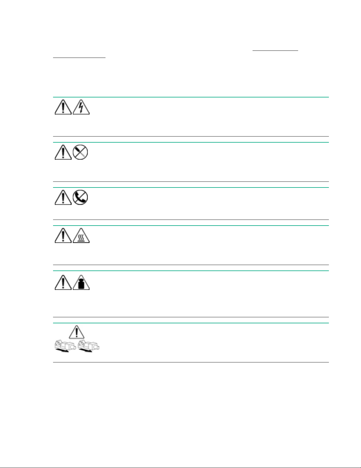
Symbols on equipment
The following symbols might be found on the equipment to indicate the presence of potentially hazardous
conditions.
This symbol indicates the presence of hazardous energy circuits or electric shock
hazards. Refer all servicing to qualified personnel.
WARNING: To reduce the risk of injury from electric shock hazards, do not open this
enclosure. Refer all maintenance, upgrades, and servicing to qualified personnel.
This symbol indicates the presence of electric shock hazards. The area contains no
user or field serviceable parts. Do not open for any reason.
WARNING: To reduce the risk of injury from electric shock hazards, do not open this
enclosure.
This symbol on an RJ-45 receptacle indicates a network interface connection.
WARNING: To reduce the risk of electric shock, fire, or damage to the equipment, do
not plug telephone or telecommunications connectors into this receptacle.
weight in kg
weight in lb
This symbol indicates the presence of a hot surface or hot component. If this surface is
contacted, the potential for injury exists.
WARNING: To reduce the risk of injury from a hot component, allow the surface to cool
before touching.
This symbol indicates that the component exceeds the recommended weight for one
individual to handle safely.
WARNING: To reduce the risk of personal injury or damage to the equipment,
observe local occupational health and safety requirements and guidelines for manual
material handling.
These symbols, on power supplies or systems, indicate that the equipment is supplied
by multiple sources of power.
WARNING: To reduce the risk of injury from electric shock, remove all power cords to
disconnect power from the system completely.
12 Troubleshooting preparation
Page 13
Warnings and cautions
WARNING: Only authorized technicians trained by Hewlett Packard Enterprise should attempt to
repair this equipment. All troubleshooting and repair procedures are detailed to allow only
subassembly/module-level repair. Because of the complexity of the individual boards and
subassemblies, no one should attempt to make repairs at the component level or to make
modifications to any printed wiring board. Improper repairs can create a safety hazard.
WARNING: To reduce the risk of personal injury or damage to the equipment, consult the safety
information and user documentation provided with the server before attempting the installation.
Some servers contain high energy circuits, high current circuits, moving parts (such as fan blades),
or any combination of these hazards, that may be exposed if covers and access panels are
removed while the product is connected to a power source. These products are intended to be
serviced only by qualified personnel who have been trained to deal with these hazards. Do not
remove enclosures or attempt to bypass any interlocks designed to guard against these hazardous
conditions.
WARNING: To reduce the risk of personal injury or damage to the equipment, be sure that:
• The leveling feet are extended to the floor.
• The full weight of the rack rests on the leveling feet.
• The stabilizing feet are attached to the rack if it is a single-rack installation.
• The racks are coupled together in multiple-rack installations.
• Only one component is extended at a time. A rack may become unstable if more than one
component is extended for any reason.
WARNING: To reduce the risk of electric shock or damage to the equipment:
• Do not disable the power cord grounding plug. The grounding plug is an important safety feature.
• Plug the power cord into a grounded (earthed) electrical outlet that is easily accessible at all
times.
• Unplug the power cord from the power supply to disconnect power to the equipment.
• Do not route the power cord where it can be walked on or pinched by items placed against it.
Pay particular attention to the plug, electrical outlet, and the point where the cord extends from
the compute module.
Troubleshooting preparation 13
Page 14
weight in kg
weight in lb
CAUTION: To properly ventilate the system, you must provide at least 7.6 cm (3.0 in) of clearance
at the front and back of the server.
CAUTION: The server is designed to be electrically grounded (earthed). To ensure proper
operation, plug the AC power cord into a properly grounded AC outlet only.
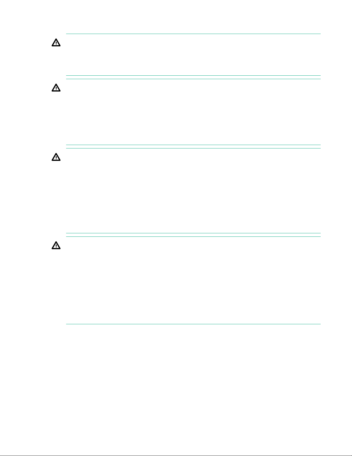
Electrostatic discharge
WARNING: To reduce the risk of personal injury or damage to the
equipment:
• Observe local occupation health and safety requirements and
guidelines for manual handling.
• Obtain adequate assistance to lift and stabilize the chassis during
installation or removal.
• The server is unstable when not fastened to the rails.
• When mounting the server in a rack, remove the power supplies and
any other removable module to reduce the overall weight of the
product
Electrostatic discharge
Be aware of the precautions you must follow when setting up the system or handling components. A
discharge of static electricity from a finger or other conductor may damage system boards or other staticsensitive devices. This type of damage may reduce the life expectancy of the system or component.
To prevent electrostatic damage:
• Avoid hand contact by transporting and storing products in static-safe containers.
• Keep electrostatic-sensitive parts in their containers until they arrive at static-free workstations.
• Place parts on a grounded surface before removing them from their containers.
• Avoid touching pins, leads, or circuitry.
• Always be properly grounded when touching a static-sensitive component or assembly. Use one or
more of the following methods when handling or installing electrostatic-sensitive parts:
◦ Use a wrist strap connected by a ground cord to a grounded workstation or computer chassis. Wrist
straps are flexible straps with a minimum of 1 megohm ±10 percent resistance in the ground cords.
To provide proper ground, wear the strap snug against the skin.
◦ Use heel straps, toe straps, or boot straps at standing workstations. Wear the straps on both feet
when standing on conductive floors or dissipating floor mats.
◦ Use conductive field service tools.
◦ Use a portable field service kit with a folding static-dissipating work mat.
If you do not have any of the suggested equipment for proper grounding, have an authorized reseller
install the part.
14 Troubleshooting preparation
Page 15

For more information on static electricity or assistance with product installation, contact an authorized
reseller.
Collecting symptom information
Before troubleshooting an issue, collect the symptom information. Download the Active Health System
Log using the Active Health System Viewer, if possible. For more information about downloading the
Active Health System Log using the AHSV, see the HPE Active Health System Viewer User Guide on the
Hewlett Packard Enterprise website (http://www.hpe.com/support/ahsv-docs).
For more information about collecting symptom information, use Symptom information checklist.
More information
Symptom information checklist on page 110
Preparing HPE Synergy for diagnosis
Procedure
1. Be sure that HPE Synergy is in the proper operating environment with adequate power, air
conditioning, and humidity control.
For required environmental conditions, see the product QuickSpecs on the Hewlett Packard Enterprise
website (http://www.hpe.com/info/qs).
2. Capture an HPE OneView support dump.
For more information, see the HPE OneView Online Help embedded in HPE OneView user interface
or in the Hewlett Packard Enterprise website (http://www.hpe.com/info/synergy-docs).
3. Remove all CDs, DVDs, USB drive keys, or SD cards that are not bootable devices.
4. Collect all tools and utilities necessary to troubleshoot the issue. Gather items such as a Torx
screwdriver, loopback adapters, ESD wriststrap, and software utilities.
For more information, see the product maintenance and service guide on the Hewlett Packard
Enterprise website (http://www.hpe.com/info/synergy-docs).
5. Review and collect the following information:
a. Review all HPE OneView errors.
b. Obtain a record of all current ROM settings by running CONREP from Scripting Toolkit for Windows
and Linux.
c. Review the IML.
d. Review the iLO information on both the Overview and the System Information page.
e. Review the Diagnostics page.
f. Use the Active Health System Viewer to download the Active Health System log.
For more information, see the Active Health System Viewer documentation on the Hewlett Packard
Enterprise website (http://www.hpe.com/support/ahsv-docs).
g. Record survey data.
6. Disconnect any peripheral devices not required for testing (any devices not necessary to power up
HPE Synergy).
Troubleshooting preparation 15
Page 16

More information
Active Health System Viewer on page 87
Active Health System log on page 86
User guide on page 99
Integrated Management Log on page 93
16 Troubleshooting preparation
Page 17

Using HPE OneView to troubleshoot the appliance
Troubleshooting tools in HPE OneView
HPE OneView has a variety of troubleshooting tools you can use to resolve issues. By following a
combined approach of examining screens and logs, you can obtain a history of activity and the errors
encountered.
• The Activity screen displays a log of all changes made on the appliance, whether user-initiated or
appliance-initiated. It is similar to an audit log, but with finer detail and it is easier to access from the
UI.
The Activity screen also provides a log of health alerts and status notifications.
• Download an audit log to help you or an administrator understand what security relevant actions took
place on the system.
• Create a support dump file to gather logs and other information required for debugging into an
encrypted, compressed file that you can send to your authorized technical support for analysis.
• Review reports for interconnect, server, and enclosure status. Reports can also provide inventory
information and help you see the types of server models and processors in your data center. They can
also show you what firmware needs to be updated.
NOTE: If the UI is not available, you can use the HPE OneView Maintenance console for troubleshooting.
For more information about using HPE OneView, see the information within the HPE OneView interface
and the HPE OneView documentation on the Hewlett Packard Enterprise website (http://www.hpe.com/
info/synergy-docs).
Using HPE OneView to troubleshoot the appliance 17
Page 18

Updating the firmware
The following instructions provide an overview of the firmware update process for HPE Synergy. For more
information, see the Best Practices for HPE Synergy Firmware and Driver Updates in the Hewlett Packard
Enterprise Information Library (
The following components require updates:
• HPE Synergy Composer
• HPE Synergy Image Streamer
• Shared infrastructure (frame link modules, interconnect modules, and I/O adapters)
• Compute modules
IMPORTANT: Hewlett Packard Enterprise recommends that you update the components in the
following order:
1. HPE Synergy Composer
2. HPE Synergy Image Streamer
3. Infrastructure components and compute modules
www.hpe.com/info/synergy-docs).
Procedure
1. Download the HPE Synergy software release from the Hewlett Packard Enterprise website (http://
www.hpe.com/downloads/synergy).
2. Ensure that you have fulfilled all critical prerequisites.
3. Perform a backup of your HPE Synergy components before updating your firmware.
4. Update the firmware for HPE Synergy Composer.
5. Update the firmware for HPE Synergy Image Streamer.
6. Update shared infrastructure and stage firmware on compute modules using the orchestrated update
method initiated through a logical enclosure.
7. Reboot during a maintenance window to activate firmware on compute modules.
18 Updating the firmware
Page 19

Common troubleshooting procedures
Consoles used with HPE Synergy
HPE Synergy Console
The HPE Synergy Console provides access to HPE OneView, frame health information, appliance
maintenance consoles, serial console access to interconnect modules, and access to iLO Integrated
Remote Console for compute modules within the frame. For more information, see the HPE Synergy
Frame Link Module User Guide on the Hewlett Packard Enterprise website (http://www.hpe.com/info/
synergy-docs).
NOTE: To access HPE OneView, the frame must either have an HPE Synergy Composer installed or be
claimed by HPE OneView.
Maintenance consoles
• HPE OneView Maintenance Console—For more information, see the HPE OneView documentation on
the Hewlett Packard Enterprise website (http://www.hpe.com/info/synergy-docs).
• HPE Synergy Image Streamer maintenance console—For more information, see the HPE Synergy
Image Streamer documentation on the Hewlett Packard Enterprise website (http://www.hpe.com/
info/synergy-docs).
Other consoles
Other consoles are available in HPE Synergy, but the ones discussed in this section are most commonly
referenced in this document.
Accessing the HPE OneView maintenance console from the frame link module
Procedure
1. Connect locally to the HPE Synergy console.
2. Select the Screen icon at the top right of the page.
3. Select an HPE Synergy Composer appliance from the Appliances menu.
A blank text window appears.
4. Press Enter.
5. At the login prompt, log in using the username: maintenance.
The HPE OneView maintenance console opens.
For additional instructions on using the HPE OneView maintenance console, see the HPE OneView User
Guide for HPE Synergy on the
Hewlett Packard Enterprise website.
Common troubleshooting procedures 19
Page 20

Connecting to the HPE OneView maintenance console using SSH
NOTE: Hewlett Packard Enterprise recommends the use the following tools for accessing the HPE
OneView maintenance console through an SSH connection:
• PuTTY
• MTPuTTY
Procedure
1. Open one of the recommended tools on your local computer.
2. Access the appliance by specifying its fully qualified domain name or its IP address.
3. Enter the following user name at the login prompt:
maintenance
4. Log in to the HPE OneView maintenance console.
5. Provide the local administrator credentials when prompted.
Creating a support dump file
This procedure describes how to use the HPE Synergy maintenance console to create a support dump
file from the local appliance (the appliance on which the HPE Synergy maintenance console runs) and
store it on a USB drive.
If the local appliance is the active appliance in an appliance cluster and if the standby appliance is
reachable, the support dump contains the data for both cluster members. Otherwise, a support dump is
created with data for the local appliance only.
The support dump file is encrypted by default.
CAUTION: Creating the support dump file overwrites any existing backup file on the appliance. If
possible, refrain from creating a support dump if you have not copied the backup file to an external
location for safekeeping.
Prerequisites
• Minimum required privileges: Infrastructure administrator
• Use a USB 2.0 or 3.0 device drive, formatted as an NTFS or FAT32 file system and with only one
partition. If necessary, use a computer to format the USB drive.
• The USB drive must have enough free space (typically 1 GB to 4 GB) to store the support dump file.
Creating a support dump file from the HPE Synergy maintenance console
Procedure
1. Ensure that the USB drive is installed in the USB port of the local appliance.
IMPORTANT: Do not remove the USB drive until the operation is complete and the Synergy
maintenance console advises that it is safe to remove the drive.
2. Use the appliance console to access the HPE Synergy maintenance console main menu.
20 Common troubleshooting procedures
Page 21

3. Select Support dump.
A new set of commands appears.
4. Do one of the following:
• Select Create support dump to create a support dump and copy it to the USB drive.
• Select Download existing support dump to copy a support dump from the appliance to the USB
drive.
5. Wait until the support dump file is copied. There is a message on the screen stating that the support
dump was successfully completed and that it is safe to remove the USB drive.
Connect to the HPE Synergy Console
You can connect to the Synergy Console using a laptop computer or a keyboard, video monitor, and
mouse.
The Synergy Console provides access to HPE OneView running on an HPE Synergy Composer
appliance.
The Synergy Console also provides access to the serial console for modules installed within a frame,
including management appliances, interconnects, or compute modules. To access the serial console for a
module, connect to the Synergy Console through ports in the same frame as the module.
IMPORTANT: For initial hardware install, identify a frame that contains a Synergy Composer. To
access HPE OneView before hardware setup is complete, access the Synergy Console through the
identified frame.
Connecting to the HPE Synergy Console using a keyboard, video monitor, and mouse
NOTE: This procedure describes connecting a keyboard and mouse to a monitor with an integrated USB
hub. Alternatively, you can use a standalone USB hub to connect a keyboard and mouse.
Prerequisites
A frame link module is installed in a frame link module bay.
Procedure
1. Connect a monitor cable to the monitor port and connect a USB cable to the USB port on either:
• The front panel module on the front of the frame.
Common troubleshooting procedures 21
Page 22
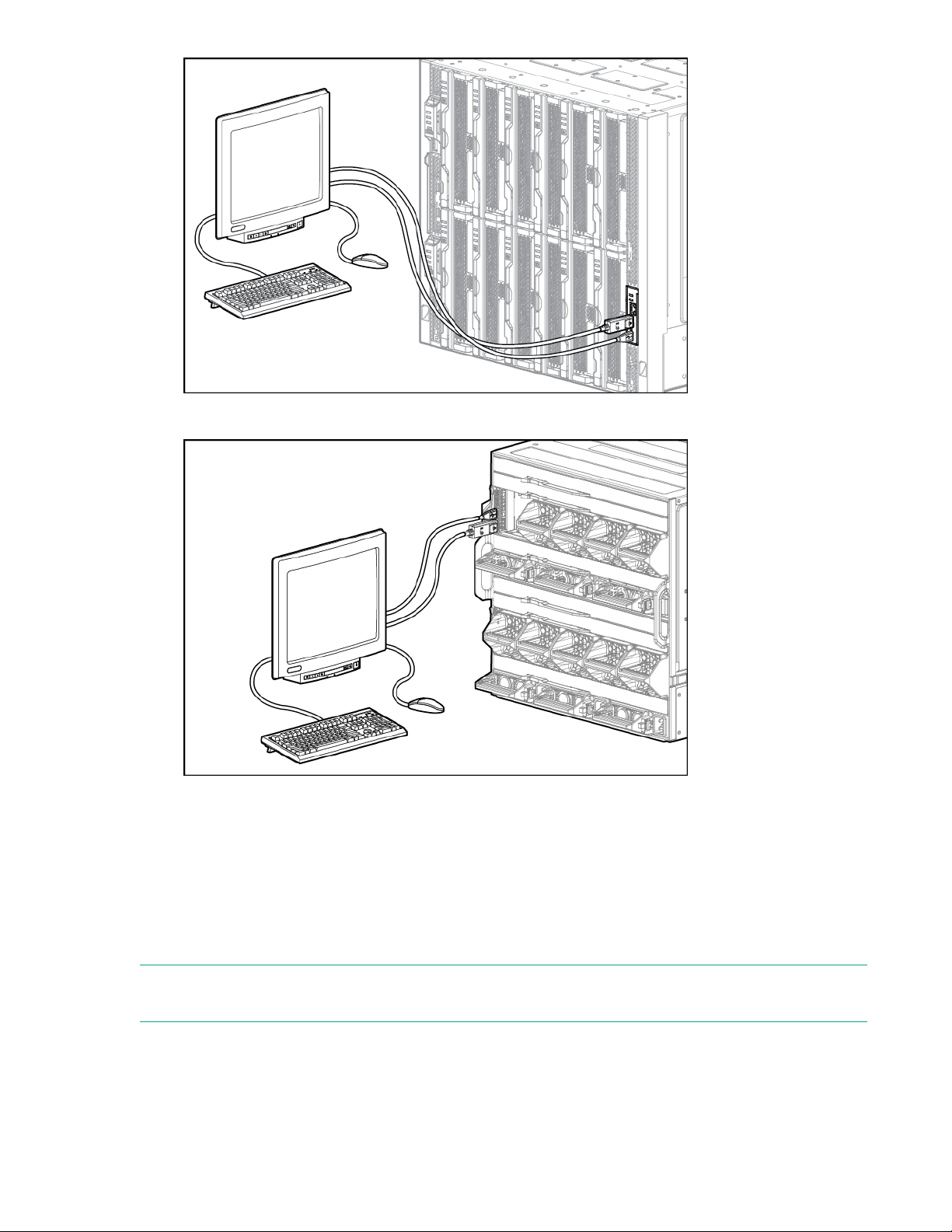
• Either frame link module on the rear of the frame.
2. Connect a monitor to the frame with the monitor cable.
3. Connect a USB keyboard and mouse to the USB ports on the monitor, and connect the monitor USB
to the frame with the USB cable.
Alternatively, connect the USB keyboard and mouse to a USB hub connected to the frame.
Connecting to the HPE Synergy Console using a laptop computer
NOTE: Do not plug the front panel laptop port into a switch. The front panel laptop port is designed to
provide a single laptop access to HPE Synergy Console.
Prerequisites
At least one frame link module is installed in one of the frame link module bays.
22 Common troubleshooting procedures
Page 23
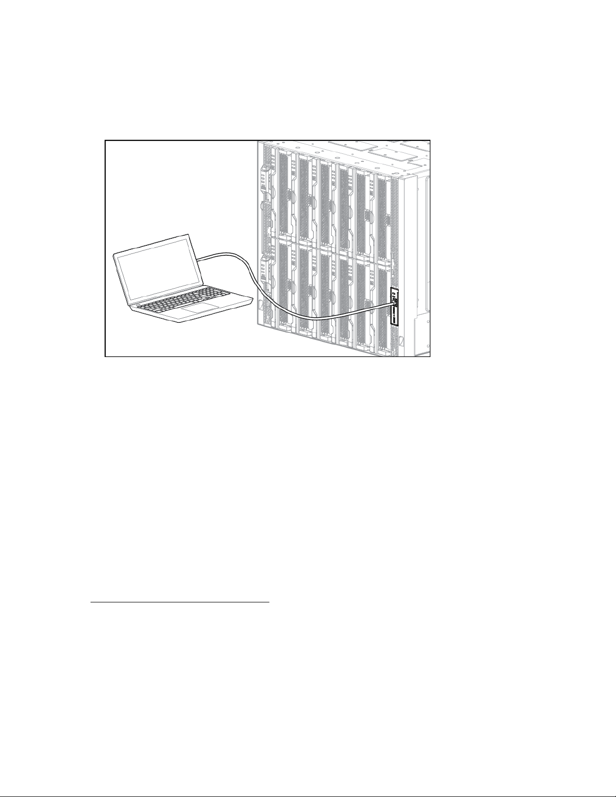
Procedure
1. Ensure that the Ethernet port of the laptop computer is configured for DHCP.
Alternatively, you can configure the laptop Ethernet port to the IP address: 192.168.10.2 with the
subnet mask 255.255.255.0.
2. Use a CAT5 cable to connect the laptop computer Ethernet port to the laptop port on a front panel
module.
3. Wait for the laptop computer to be assigned an IP address from the frame link module.
4. Access the HPE Synergy Console using either a VNC client or web browser.
a. Web browser: Open a web browser and enter http://192.168.10.1.
Alternatively, you can include the port number.
http://192.168.10.1:5800
b. VNC client: Open a VNC client and connect to 192.168.10.1 port 5900.
A VNC client will load to the web browser and open the HPE Synergy Console.
Connecting to HPE OneView using the HPE Synergy Console
Prerequisites
Connect to the HPE Synergy Console on page 21.
Procedure
1. When connected, the Synergy console buffer screen appears while the GUI is opening.
On initial power-up, the Synergy Composers can take up to 10 minutes before you can connect to
them.
2. Verify the health status for all installed components in the Synergy Console Frame Healthy & Inventory
screen. All components should be green before you connect to HPE OneView.
Common troubleshooting procedures 23
Page 24
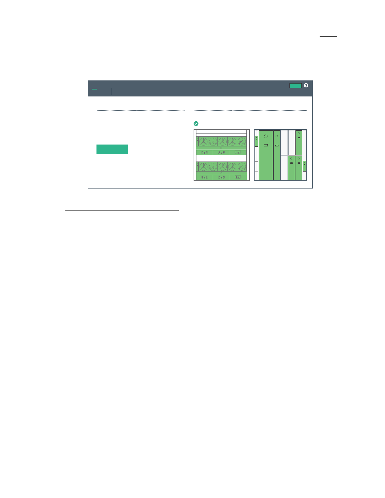
If any components are not green, use the information on the screen to troubleshoot the issue with the
Synergy Console
Home
Actions
OneView
Frame Link Module Ports
Click “Connect” to start OneView
Not Claimed.
Connect
Frame Health & Inventory >
Synergy 12000 Frame XXXXXXXXX
Hewlett Packard
Enterprise
component. For more information, see the HPE Synergy Frame Link Module User Guide at http://
www.hpe.com/info/synergy-docs.
3. Select Connect.
HPE OneView can take up to 18 minutes for initial startup.
4. Verify installation using HPE OneView.
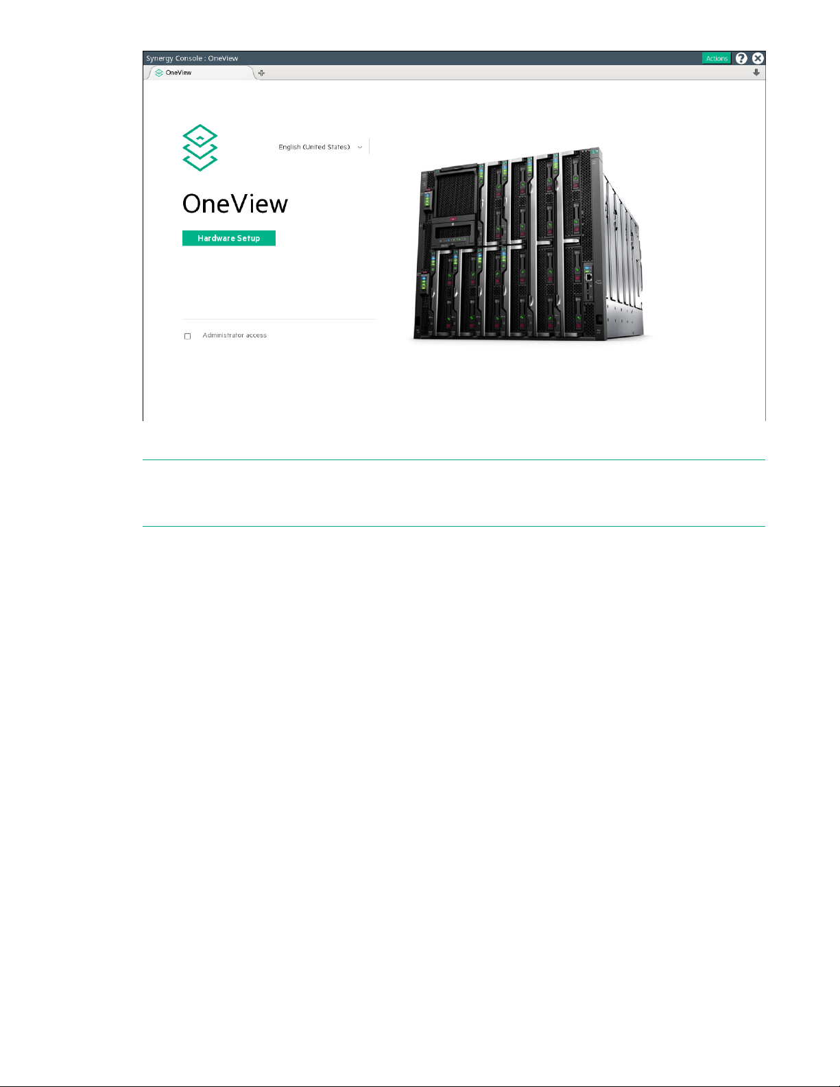
Verifying installation using HPE OneView
Procedure
1. From the Synergy Console, click Connect to start HPE OneView.
2. To connect with install technician user privileges, click Hardware Setup.
To connect as Administrator, select the Administrator access check box.
24 Common troubleshooting procedures
Page 25
3. Review the hardware inventory.
NOTE: A spinning icon at the top of the inventory section indicates when HPE OneView is bringing the
enclosures and the devices within them under management. Devices might not be listed until the
discovery process is complete.
a. Wait for HPE OneView to complete the add operation.
b. Confirm that the inventory includes all installed components.
c. For any hardware not discovered by HPE OneView, look for problems with frame link module
cabling, hardware not fully inserted, or other hardware issues.
4. Review and correct any issues listed in the Hardware Setup Checklist.
a. To troubleshoot all issues, follow corrective actions in HPE OneView.
b. Return to the Hardware Setup screen and check for additional issues until the Checklist indicates
Setup complete.
For more information about using HPE OneView, see the online help by clicking the question mark on
the top bar of the HPE Synergy Console.
5. (Optional) Select Edit networking from the Hardware Setup screen.
Edit the HPE OneView networking settings and click OK. The Maintenance IP address fields are
required unless you have disabled service console access.
6. To add a remote enclosure, select Actions > Add remote enclosures from the Hardware Setup
screen.
Enter the IPv6 address of a frame link module that is connected to a frame in the remote frame link
topology. The remote frame link topology must be in the same subnet as the primary frame link
topology.
Common troubleshooting procedures 25
Page 26

7. Unmanaged interconnect modules require console access for initial setup. Click the Actions menu on
the top bar of the HPE Synergy Console and select the module from the Serial Consoles >
Interconnects menu. Press the Enter key to begin the serial console session with that interconnect
module. Configure the interconnect module using the instructions provided with the module. To close
the session, click the X in the top right corner.
NOTE: To access the serial console for an interconnect module, connect to the HPE Synergy Console
through ports in the same frame as the module.
For more information, see the procedures for connecting to the HPE Synergy Console.
8. Log out from the HPE OneView Hardware Setup session.
To close the session, click the X in the top right corner of the Synergy console.
After hardware setup is complete, the system is ready to be configured for a production environment.
An HPE OneView administrator can perform configuration tasks with an account that provides
additional user privileges.
For more information about HPE OneView administration, see the HPE OneView online help or the
HPE OneView User Guide for Synergy.
For operating system deployment options on HPE Synergy, see the HPE Synergy 12000 Frame Setup
and Installation Guide.
Frame link module factory reset
IMPORTANT: When a frame is configured and is actively managed by HPE OneView, a factory
reset should only be performed when required by a recommended HPE OneView management or
service process.
The Factory Reset action resets all frame link modules in a frame to factory default settings. Resetting a
frame link module to factory default settings will take the frame link module offline for up to 10 minutes. If
the frame link module is installed in a frame managed by HPE OneView, the frame link module will be
reclaimed by HPE OneView after the factory reset is complete.
Some instances where a factory reset may be necessary include:
• Prior to moving a frame to a new HPE OneView environment.
• After performing a factory reset of the HPE Synergy Composer that manages the frame.
For more information, see the HPE OneView for Synergy User Guide on the Hewlett Packard
Enterprise Information Library (http://www.hpe.com/info/synergy-docs).
Performing a frame link module factory reset
NOTE: This procedure only factory resets the frame link modules installed in the frame. It does not factory
reset any other components installed in the frame.
NOTE: The frame link module can be factory reset by pressing the front panel reset button until the front
panel UID flashes or by using the HPE Synergy Console Actions menu. Hewlett Packard Enterprise
recommends using the HPE Synergy Console to perform a factory reset.
26 Common troubleshooting procedures
Page 27

Procedure
1. Connect to the HPE Synergy Console.
2. Select Actions > FLM Diagnostics > Factory Reset.
A progress bar displays.
Resetting a frame link module
The Reboot action performs a reset of either the Active or Standby frame link module.
NOTE: Resetting a frame link module will cause a brief disruption of the management ring network. The
disruption may last up to 30 seconds.
Procedure
1. Connect to the HPE Synergy Console.
2. Select Actions > FLM Diagnostics > Reboot.
The reboot pop-up window appears.
3. Choose either the Active or Standby frame link module.
Processor troubleshooting guidelines
Troubleshooting processors on an HPE Synergy Gen9 compute module
CAUTION: When reducing the compute module to a minimum configuration for troubleshooting, do
not remove additional processors unless requested by the Hewlett Packard Enterprise Support
Center. Improperly replacing or reseating processors can result in damage to the system board.
Troubleshooting processors on an HPE Synergy Gen10 compute module
CAUTION: When reducing Gen10 servers or compute modules to a minimum configuration for
troubleshooting, do not remove additional processors. Processor and heatsinks are not designated
for customer self repair. The processor and heatsink must be removed and replaced by an
authorized service provider.
Before performing any troubleshooting steps that involve processors, review the following guidelines:
• Be sure that only authorized personnel perform the troubleshooting steps that involve installation,
removal, or replacement of a processor.
• Always complete all other troubleshooting procedures before an authorized service provider removes
or replaces a processor.
Common troubleshooting procedures 27
Page 28

Breaking the compute module down to the minimum hardware configuration
CAUTION: When reducing Gen10 servers or compute modules to a minimum configuration for
troubleshooting, do not remove additional processors. Processor and heatsinks are not designated
for customer self repair. The processor and heatsink must be removed and replaced by an
authorized service provider.
CAUTION: When reducing Gen9 servers or compute modules to a minimum configuration for
troubleshooting, do not remove additional processors unless requested by the Hewlett Packard
Enterprise Support Center. Improperly replacing or reseating processors can result in damage to the
system board.
CAUTION: Before removing or replacing any processors, be sure to follow the Processor
troubleshooting guidelines in this document. Failure to follow the recommended guidelines can
damage the processor or system board, requiring replacement of the system board.
During the troubleshooting process, you may be asked to break the compute module down to the
minimum hardware configuration. A minimum configuration consists of only the components required to
boot the compute module and successfully pass POST.
When requested to break the compute module down to the minimum configuration, uninstall the following
components, if installed:
• All hard drives and solid-state drives
• All SFF flash storage adapters
• All optional mezzanine cards
• microSD card
• USB devices
• Energy pack (an HPE Smart Storage Battery or HPE Smart Storage Hybrid Capacitor)
Before removing the components, be sure to determine the minimum configuration for each component
and follow all guidelines in the compute module user guide.
Always use the recommended minimum configuration before removing any processors or DIMMs.
28 Common troubleshooting procedures
Page 29

Common issue resolution
Resolving loose connections
• Be sure all power cords are securely connected.
• Be sure all cables are properly aligned and securely connected for all external and internal
components.
• Remove and check all data and power cables for damage. Be sure no cables have bent pins or
damaged connectors.
• If a cable routes through air baffles or other components, be sure the cords and cables connected to
the compute module are routed correctly through the baffle.
• Be sure each device is properly seated. Avoid bending or flexing circuit boards when reseating
components.
• If a device has latches, be sure they are completely closed and locked.
• Check any interlock or interconnect LEDs that might indicate a component is not connected properly.
• If issues continue to occur, remove and reinstall each device, checking the connectors and sockets for
bent pins or other damage.
Searching for service notifications
Service notifications are created to provide solutions for known issues. Check to see if your issue is
covered by an existing service notification.
Procedure
1. See the Hewlett Packard Enterprise website (http://www.hpe.com/support/hpesc).
2. Enter the product name or number, and then press Enter.
3. To show the documents available for your product, select Documents.
4. To narrow the results, select from the available options to filter by document type.
Some of the document types you may include are as follows:
• Advisory—Provides a problem and solution to an issue or a workaround.
• Bulletin or Security Bulletin—Provides information about a potential product safety or security
vulnerability.
• Notice—Provides general information, announcements, or best practices.
Component LED definitions and component information
Many common issues can be identified by reviewing the LEDs. For more information, see the HPE
Synergy documentation on the Hewlett Packard Enterprise website (http://www.hpe.com/info/synergy-
docs).
Common issue resolution 29
Page 30
Intel Xeon Scalable Processors supported on HPE ProLiant Gen10 servers
Depending on the compute module, HPE ProLiant Gen10 servers can support either first or secondgeneration Intel Xeon Scalable processors.
To determine the generation, look at the four-digit processor model number.
• If the second digit is a 1 (X1XX), you have a First Generation Intel Xeon Scalable processor.
• If the second digit is a 2 (X2XX), you have a Second Generation Intel Xeon Scalable processor.
IMPORTANT: Existing HPE ProLiant and HPE Synergy Gen10 server products containing First
Generation Intel Xeon Scalable Processors may not be upgraded to Second Generation Intel Xeon
Scalable Processors at this time. For more information, see the product QuickSpecs on the Hewlett
Packard Enterprise website (http://www.hpe.com/info/qs).
DIMM and NVDIMM population information
For specific DIMM and NVDIMM population information, see the DIMM population guidelines on the
Hewlett Packard Enterprise website (http://www.hpe.com/docs/memory-population-rules).
DIMM-processor compatibility
The installed processor determines the type of DIMM that is supported in the compute module:
• First Generation Intel Xeon Scalable Processors support DDR4-2666 DIMMs.
• Second Generation Intel Xeon Scalable Processors support DDR4-2933 DIMMs.
Mixing DIMM types is not supported. Install only the supported DDR4-2666 or DDR4-2933 DIMMs in the
compute module.
NVDIMM-processor compatibility
HPE 16GB NVDIMMs are only supported in servers with first generation Intel Xeon Scalable processors
installed.
DIMM handling guidelines
CAUTION: Failure to properly handle DIMMs can damage DIMM components and the system board
connector.
When handling a DIMM, observe the following guidelines:
• Avoid electrostatic discharge.
• Always hold DIMMs by the side edges only.
• Avoid touching the connectors on the bottom of the DIMM.
• Never wrap your fingers around a DIMM.
• Avoid touching the components on the sides of the DIMM.
• Never bend or flex the DIMM.
When installing a DIMM, observe the following guidelines:
30 Common issue resolution
Page 31

• Before seating the DIMM, open the DIMM slot and align the DIMM with the slot.
• To align and seat the DIMM, use two fingers to hold the DIMM along the side edges.
• To seat the DIMM, use two fingers to apply gentle pressure along the top of the DIMM.
For more information, see the Hewlett Packard Enterprise website (http://www.hpe.com/support/
DIMM-20070214-CN).
Common issue resolution 31
Page 32
Hardware issues
Procedures for troubleshooting HPE Synergy components
The procedures in this section are comprehensive and include steps about or references to hardware
features. The features in this section may not be supported by all compute modules or components you
are troubleshooting.
Many of the troubleshooting procedures are intended as a list of troubleshooting steps. The first step may
resolve the issue or multiple steps may be needed. Complete the first step, and then verify that the
condition still exists before proceeding to the next step.
CAUTION: Before removing or replacing any processors, be sure to follow the guidelines provided
in "Processor troubleshooting guidelines on page 27." Failure to follow the recommended
guidelines can damage the system board, requiring replacement of the system board.
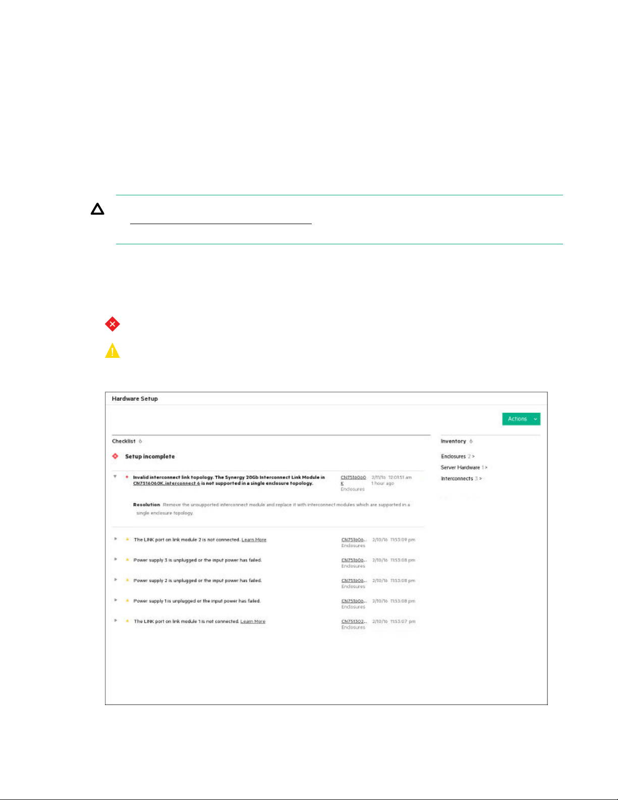
Issues during installation
During the hardware setup, any installation errors are returned on the final checklist. See the following
image as an example:
• —Indicates a critical error that must be corrected.
• —Indicates a warning that can be corrected, but is not mandatory. For hardware issues, this
warning could mean that redundancy has been lost and additional failures would cause a loss of
service.
32 Hardware issues
Page 33

To correct the errors that appear, select the hyperlink to the right of the suggested corrective action, and
then follow any additional steps suggested on the screen.
Frame and frame link module
The frame link module is unresponsive and pressing the reset button does not reset the frame link module
Symptom
The frame link module management traffic freezes or a frame link module is unresponsive and pressing
the frame link module reset button does not reset the frame link module.
Action
1. Remove the frame link module from the frame.
For more information, see the HPE Synergy 12000 Frame Maintenance and Service Guide on the
Hewlett Packard Enterprise website (http://www.hpe.com/info/synergy-docs).
2. Reinstall the frame link module in the original bay.
All management traffic stops while the frame link module reboots. The frame link module comes back
online as soon as the frame link module reset is complete.
For more information, see the HPE Synergy 12000 Frame Maintenance and Service Guide on the
Hewlett Packard Enterprise website (http://www.hpe.com/info/synergy-docs).
Frame power and cooling
A device is not allowed to power on due to insufficient cooling in the frame
Symptom
• A device fails to power on.
• A message is displayed in HPE OneView.
Cause
A device in a specific bay could not power on because the frame does not have the necessary fan
configuration to meet the cooling requirements. All fan bays are required to have operational fans
installed.
Action
1. Verify that all fans are installed and operational in the frame.
2. Install or replace fans in the frame.
For more information, see the HPE Synergy 12000 Frame Setup and Installation Guide on the Hewlett
Packard Enterprise website (http://www.hpe.com/info/synergy-docs).
Hardware issues 33
Page 34

A device is not allowed to power on due to insufficient power in the frame
Symptom
A message is displayed in HPE OneView.
Cause
A device in a specific bay could not power on because the frame does not have the necessary power
supply configuration to meet the power allocation at the current power mode.
Action
1. Verify the power supply and power mode requirements for the frame.
For more information, see the HPE Synergy Configuration and Compatibility Guide on the Hewlett
Packard Enterprise website (http://www.hpe.com/info/synergy-docs).
2. Install additional power supplies in the frame or replace nonoperational power supplies.
For more information on installing power supplies in the frame, see the HPE Synergy 12000 Frame
Setup and Installation Guide on the Hewlett Packard Enterprise website (http://www.hpe.com/info/
synergy-docs).
General UPS issues
Symptom
UPS is not working properly.
Cause
• The UPS switch is not in the On position.
• The UPS batteries are not charged to the proper level.
• The UPS software is not up-to-date.
• The UPS power cord is not connected.
• The UPS power cord is not the correct type for the UPS and the country/region in which the compute
module is located.
Action
1. Verify that the UPS batteries are charged to the proper level for operation.
For more information, see the UPS documentation.
2. Verify that the UPS power switch is in the On position.
For the location of the switch, see the UPS documentation.
3. Verify that the UPS software is updated to the latest version.
Use the Power Management software on the Hewlett Packard Enterprise website (http://
www.hpe.com/info/rackandpower).
4. Verify that the power cord is the correct type for the UPS and the country/region in which the server is
located.
34 Hardware issues
Page 35

For specifications, see the UPS reference guide.
5. Verify that the line cord is connected.
6. Verify that each circuit breaker is in the On position, or replace the fuse if needed.
If this issue occurs repeatedly, contact an authorized service provider.
7. To verify that a battery or site wiring issue has not occurred, check the UPS LEDs.
See the UPS documentation.
8. If the UPS sleep mode is initiated, disable sleep mode for proper operation.
The UPS sleep mode can be turned off through the configuration mode on the front panel.
9. To verify that the damage is not caused by excessive heat, change the battery.
Be sure to complete this step if a recent air conditioning outage occurred.
NOTE: The optimal operating temperature for UPS batteries is 25°C (77°F). For approximately every
8°C to 10°C (16°F to 18°F) average increase in ambient temperature above the optimal temperature,
battery life is reduced by 50 percent.
Low battery warning is displayed on the UPS
Symptom
A low battery warning is displayed on the UPS.
Cause
• The batteries need to be charged.
• The batteries are failing to hold a charge.
• The batteries are faulty.
Action
1. Plug the UPS into an AC grounded outlet for at least 24 hours to charge the batteries.
2. Test the batteries.
3. Replace the batteries if necessary.
4. Be sure the alarm is set appropriately by changing the amount of time given before a low battery
warning. For more information, see the UPS documentation.
One or more LEDs on the UPS is red
Symptom
One or more of the UPS LEDs is red.
Action
For product-specific LED information and additional troubleshooting information, see the UPS
documentation.
Hardware issues 35
Page 36

Fans running at a higher than expected speed
Symptom
The fans are running at a higher speed than expected.
Cause
• The system temperature sensor is reading within approximately 10°C of the Caution threshold.
• An air baffle or blank is missing or not installed properly and causing a disruption of the airflow.
• The processor heatsink is not installed as indicated in the compute module documentation.
• A supported fan is not installed in the frame.
Action
1. Update the compute module to the latest firmware versions, such as iLO firmware, system BIOS,
option firmware.
2. Verify the Fan status using Fans section of the HPE OneView Enclosures screen.
For more information, see HPE OneView Help or the HPE OneView User Guide on the Hewlett
Packard Enterprise website (
3. Verify the Temperature tab in HPE iLO.
http://www.hpe.com/info/synergy-docs).
Fan speeds can be high if a sensor temperature is within approximately 10°C of the Caution threshold.
4. Verify that all air baffles and required blanks are installed.
Examples of required blanks include drive blanks, processor heatsink blanks, and power supply
blanks.
For product-specific information, see the HPE Synergy documentation in the Hewlett Packard
Enterprise website (http://www.hpe.com/info/synergy-docs).
Excessive fan noise (high speeds)
Symptom
Fans are operating at high speeds with excessive noise.
Cause
Fans can generate noise:
• When running at a high speed (as expected)
• When at low speed if there is an issue with the fan
Action
1. Verify the fan status and fan speed by accessing the Fans view of the HPE OneView Enclosures
screen.
For more information, see the HPE OneView User Guide on the Hewlett Packard Enterprise website
(http://www.hpe.com/info/synergy-docs).
36 Hardware issues
Page 37

Fan speeds greater than 60% are expected to be loud.
2. If the fan is running at a speed higher than expected, see "Fans running at a higher than expected
speed."
More information
Fans running at a higher than expected speed on page 36
Excessive fan noise (low speeds)
Symptom
An abnormal or rattling noise observed at low fan speeds might indicate an issue with the fan.
Action
Replace the fan.
For more information, see the HPE Synergy 12000 Frame Maintenance and Service Guide on the
Hewlett Packard Enterprise website (http://www.hpe.com/info/synergy-docs).
Appliance module
The appliance module firmware is not compatible with the current HPE Synergy software release
Symptom
HPE OneView displays errors when a new or updated appliance module is installed.
Cause
A new or updated appliance module is installed in HPE Synergy with a firmware version that is not
compatible with the firmware on another appliance in the same management ring.
Action
Validate the appliance firmware.
If installing a new appliance module, see the Hewlett Packard Enterprise website (http://www.hpe.com/
info/synergy-fw-validation).
If the appliance module was updated to replace the drive or the system board, see the appliance
maintenance and service guide on the Hewlett Packard Enterprise website (http://www.hpe.com/info/
synergy-docs).
The appliance module cannot be discovered by the frame link module
Symptom
A message is displayed in HPE OneView indicating that the appliance module cannot be discovered by
the frame link module.
Hardware issues 37
Page 38

Cause
• After the appliance module was installed, the appliance module did not initiate communication with the
frame link module within the timeout period.
• After receiving communication from the frame link module, the GPIO presence signal was not received
within the timeout period.
• The appliance module data is either corrupt or could not be read.
• An error was encountered while trying to communicate with the iLO on the appliance module.
Action
1. Remove the appliance module from the appliance bay.
2. Reinstall the appliance module in the same appliance bay.
For more information, see the appliance maintenance and service guide on the Hewlett Packard
Enterprise website (http://www.hpe.com/info/synergy-docs).
3. If the issue persists, contact Hewlett Packard Enterprise technical support.
More information
Accessing Hewlett Packard Enterprise Support on page 107
The appliance module is not compatible with the version of frame link module firmware currently installed
Symptom
A message displays that the appliance module is not compatible with the version of frame link module
firmware currently installed.
Cause
The frame link module firmware is not compatible with the appliance module installed.
Action
1. Update the frame link module firmware to a version that supports the appliance module.
2. If the issue persists, contact Hewlett Packard Enterprise technical support.
More information
Updating the firmware on page 18
Accessing Hewlett Packard Enterprise Support on page 107
38 Hardware issues
Page 39

Compute module
Firmware update and compatibility requirements
CAUTION: Before installing HPE Synergy Gen10 compute modules in an HPE Synergy 12000
Frame managed by HPE OneView 3.0, you must update your system to HPE Synergy Software
Release version 3.10.Gen10.20170721 (or later) to ensure proper functionality and support for the
HPE Synergy Gen10 compute modules.
In addition, Hewlett Packard Enterprise recommends that you use Gen10-based software releases
for all configurations. Gen10 compute modules require software releases with a naming convention
of <x.xx.GEN10.xxxxx>.
To access software releases, go to www.hpe.com/downloads/synergy. Each software release is
identified with the date the software release was posted to this website.
For more information about updating HPE Synergy firmware, see the Best Practices for HPE Synergy
Firmware and Drive Updates on the Hewlett Packard Enterprise website http://www.hpe.com/info/
synergy-docs.
System does not boot from the microSD card
Symptom
The system does not boot from the microSD card.
Cause
• The drive boot order is not set to boot from the microSD card.
• The microSD card is not detected by HPE iLO.
• The microSD card is not seated properly.
Action
1. Be sure the drive boot order in the UEFI System Utilities is set so that the compute module boots from
the microSD card.
For more information, see the UEFI System Utilities user guide for your compute module on the
Hewlett Packard Enterprise website (http://www.hpe.com/info/uefi/docs).
2. Use the HPE iLO web interface to verify that the microSD card is detected by HPE iLO.
For more information, see the appropriate document for your compute module:
• For HPE Synergy Gen10 compute modules, see the HPE iLO 5 User Guide on the Hewlett
Packard Enterprise website (http://www.hpe.com/support/ilo-docs).
• For HPE Synergy Gen9 compute modules, see the HPE iLO 4 User Guide on the Hewlett Packard
Enterprise website (http://www.hpe.com/info/ilo/docs).
3. Reseat the microSD card:
a. Power down the compute module.
b. Remove the compute module from the frame.
c. Remove the access panel.
Hardware issues 39
Page 40

d. Locate and reseat the microSD card.
e. Install the compute module in the same location in the frame.
For more information, see the compute module maintenance and service guide on the Hewlett
Packard Enterprise website (http://www.hpe.com/info/synergy-docs).
System battery is low or lost power
Symptom
An error message is received indicating low power or loss of power.
Cause
Real-time clock system battery is running low on power or lost power.
Action
Replace the battery. For more information, see the compute module maintenance and service guide on
the Hewlett Packard Enterprise website.
TPM fails or is not detected
Symptom
The TPM failed or the TPM is no longer detected.
Cause
• The TPM failed.
• The TPM is not configured properly in UEFI System Utilities.
• The boot mode is not configured for the TPM installed on the compute module.
Action
1. When a TPM is installed and used with BitLocker, be sure that the TPM is enabled in UEFI System
Utilities.
See the TPM replacement recovery procedure in the operating system documentation.
2. When a TPM is installed, be sure that the TPM is configured for a mode that is compatible with the OS
running on the compute module.
Verify that the OS supports the version of TPM installed and configured on the compute module.
3. When a TPM 2.0 is installed, verify that the compute module is configured for UEFI boot mode.
4. Leave the TPM installed and request a new system board and TPM from a Hewlett Packard Enterprise
authorized service provider.
More information
Accessing Hewlett Packard Enterprise Support on page 107
40 Hardware issues
Page 41

Procedure prerequisites with a Trusted Platform Module installed and BitLocker enabled
When a TPM is installed and enabled in the UEFI System Utilities, and when the Microsoft Windows
BitLocker Drive Encryption feature is enabled, always disable BitLocker before performing any of the
following procedures:
• Restarting the compute module or maintenance without a PIN or startup key
• Upgrading critical early boot components
• Upgrading the system board to replace or remove the TPM.
• Disabling or clearing the TPM
• Moving a BitLocker-protected drive to another compute module
• Adding an optional PCI device, such as a storage controller or network adapter
Compute module memory
Compute module is out of memory
Symptom
• The compute module is out of memory.
• A POST error message or an IML message is displayed.
Cause
• The memory is not configured properly.
• An OS error is indicated.
Action
1. Be sure the memory is configured properly.
For more information, see the DIMM population guidelines on the Hewlett Packard Enterprise website
(http://www.hpe.com/docs/memory-population-rules).
2. Be sure no operating system errors are indicated.
3. Update the system ROM to the latest version.
Memory count error exists
Symptom
A memory count error is displayed in POST or IML.
Hardware issues 41
Page 42

Cause
• The memory modules are not installed correctly.
• An OS error has occurred.
Action
1. Be sure that the memory is seated properly.
Use care when handling DIMMs.
2. Be sure that no operating system errors are indicated.
3. Restart the compute module and check to see if the error message is still displayed.
More information
DIMM handling guidelines on page 30
Compute module fails to recognize existing memory
Symptom
The compute module does not recognize existing memory.
Cause
• The compute module does not support the processor installed in the compute module.
• The associated processor is not installed for all DIMMs installed in the compute module.
• The memory is not configured properly.
• The DIMM is degraded.
• The DIMM is not installed or seated properly.
• The DIMM is not installed.
Action
1. Be sure the compute module supports the processor installed in the compute module.
For a list of supported options, see the product storage module QuickSpecs on the Hewlett Packard
Enterprise website (http://www.hpe.com/info/qs).
2. For all DIMMs installed in the compute module, be sure that the associated processor is installed.
For more information on which DIMM slots are associated with each processor, see the compute
module user guide on the Hewlett Packard Enterprise website (http://www.hpe.com/info/synergy-
docs).
3. Be sure that the memory is configured properly.
For more information, see the compute module user guide on the Hewlett Packard Enterprise website
(http://www.hpe.com/info/synergy-docs).
4. Reseat the memory.
Use care when handling DIMMs.
5. Replace all degraded DIMMs.
42 Hardware issues
Page 43

For more information, see the compute module maintenance and service guide on the Hewlett
Packard Enterprise website (http://www.hpe.com/info/synergy-docs).
6. Update the system ROM to the latest version.
More information
DIMM handling guidelines on page 30
Compute module fails to recognize new memory
Symptom
The compute module does not recognize new memory installed on the compute module.
Cause
• The memory is not supported on this compute module.
• The memory is not installed according to the compute module requirements.
• The memory limits are exceeded for the compute module.
• The processor is not supported on the compute module.
• The memory is not installed or seated properly.
Action
1. Be sure that the memory is the correct type for the compute module.
For a list of supported options, see the product QuickSpecs on the Hewlett Packard Enterprise
website (http://www.hpe.com/info/qs).
2. Be sure that the memory is installed according to the compute module requirements.
For more information, see the compute module user guide on the Hewlett Packard Enterprise
website (http://www.hpe.com/info/synergy-docs).
3. Be sure that you have not exceeded the memory limits of the compute module or operating system.
For more information, see the compute module user guide on the Hewlett Packard Enterprise
website (http://www.hpe.com/info/synergy-docs).
4. Be sure the compute module supports the number of processor cores.
Some compute module models support only 32 cores, which might reduce the amount of memory
that is visible.
5. Be sure that no Event List error messages are displayed in the IML.
6. Be sure that the memory is seated properly.
7. Be sure that no conflicts are occurring with existing memory. Run the compute module setup utility.
8. Test the memory by installing the memory into a known working compute module. Be sure that the
memory meets the requirements of the new compute module on which you are testing the memory.
9. Update the system ROM to the latest version.
10. Replace the memory.
For more information, see the compute module maintenance and service guide on the Hewlett
Packard Enterprise website (http://www.hpe.com/info/synergy-docs).
Hardware issues 43
Page 44

More information
Viewing the IML on page 93
Updating the firmware on page 18
DIMM and NVDIMM population information on page 30
NVDIMM issues
NVDIMM population errors
Symptom
• A POST error message or an IML message is displayed.
• System halts.
Cause
• An unsupported number of NVDIMMs are installed on the compute module.
• An unsupported DIMM is installed on the compute module.
• The compute module contains an unsupported mixture of DIMM types.
• NVDIMMs and RDIMMs are not installed in the correct order.
• At least one standard DIMM is not installed on Processor 1 as required by the population guidelines.
• An HPE Smart Storage Hybrid Capacitor is installed in the compute module.
Action
1. Review the IML for messages that may indicate the reason the NVDIMMs are disabled. Perform steps
stated in the error message.
For more information, see the error message guide for your compute module on the Hewlett Packard
Enterprise website (http://www.hpe.com/info/gen10-troubleshooting).
2. Verify that all DIMMs are installed according to the population guidelines.
For more information, see the memory population rules on the Hewlett Packard Enterprise website
(http://www.hpe.com/docs/memory-population-rules).
3. Remove all DIMM types that are not supported in the configuration.
For more information, see the compute module maintenance and service guide.
4. Verify that an HPE Smart Storage Battery is installed on the compute module.
The HPE Smart Storage Hybrid Capacitor does not support NVDIMMs.
NVDIMMs are disabled
Symptom
• All NVDIMMs are disabled.
• All NVDIMMs on a processor are disabled.
44 Hardware issues
Page 45

Cause
• Node interleaving is enabled.
• The current AMP mode is unsupported when NVDIMMs are installed.
• New NVDIMMs were installed on the compute module.
• The NVDIMM is installed in a slot that does not have backup power available.
Action
1. Review the IML for messages that may indicate the reason the NVDIMMs are disabled. Perform steps
stated in the error message.
For more information, see the error message guide for your compute module on the Hewlett Packard
Enterprise website (http://www.hpe.com/info/gen10-troubleshooting).
2. Ensure that all UEFI System Utility settings are configured to support NVDIMMs.
• If Node interleaving is enabled in UEFI System Utilities, change the setting to Disabled.
• If Advanced Memory Protection is set to any other setting than Advanced ECC Support, then
change the setting to Advanced ECC Support.
For more information, see the UEFI System Utilities user guide for your product on the Hewlett
Packard Enterprise website (http://www.hpe.com/info/uefi/docs).
3. If new NVDIMMs are installed on the compute module, sanitize the NVDIMMs to enable the NVDIMMs
for use.
For more information, see the HPE 16GB NVDIMM User Guide on the Hewlett Packard Enterprise
website (http://www.hpe.com/info/NVDIMM-docs).
4. Verify that your NVDIMM is installed in a slot that supports NVDIMMs. Move the NVDIMM to a slot that
supports NVDIMMs.
For more information, see the compute module maintenance and service guide.
5. Verify that a supported HPE Smart Storage Battery is properly installed and operating in the compute
module.
For a list of supported options, see the QuickSpecs on the Hewlett Packard Enterprise website (http://
www.hpe.com/info/qs).
The persistent memory drive does not appear in the OS
Symptom
When a persistent memory drive does not appear in the OS, this symptom usually indicates that the
underlying NVDIMM is mapped out.
Cause
Uncorrectable memory errors exist in the NVDIMM and address range scrubbing is not enabled.
Action
1. In UEFI System Utilities, set the Persistent Memory Address Range Scrub option to Enabled.
Hardware issues 45
Page 46

a. From the System Utilities screen, select System Configuration > BIOS/Platform Configuration
(RBSU) > Memory Options > Persistent Memory Options > Persistent Memory Integrity
Check.
b. Select Enabled.
c. Save your settings.
For more information, see the UEFI System Utilities user guide for your product on the Hewlett
Packard Enterprise website (http://www.hpe.com/info/uefi/docs).
The persistent memory drive is read only
Symptom
A persistent memory drive marked as "read only" usually indicates that the underlying NVDIMM detected
is not armed for backup during the boot process.
Solution 1
Cause
• Previous backup operation failed.
• The current restore operation failed.
• A general arming error occurred.
• An erase error occurred.
• An NVDIMM controller error occurred.
Action
Check the IML for the cause of the failure or error. Perform the action recommended in the IML.
Solution 2
Cause
The persistent memory backup power requirements exceed the available backup battery power.
Action
Remove any hardware that was recently added to the compute module.
Solution 3
Cause
The backup energy source is not sufficiently charged and the charging process was skipped by the user.
46 Hardware issues
Page 47

Action
Reboot the system and wait for the backup energy source to sufficiently charge.
Solution 4
Cause
The backup energy source is not sufficiently charged and the charging process timed out.
Action
1. Check the IML for additional backup power source-related messages and perform any recommended
actions.
2. If the issue still exists, replace the backup power source.
For more information, see the compute module maintenance and service guide.
The persistent memory drives lose persistency
Symptom
A persistent memory drive can potentially lose its ability to persist data after it has booted to the OS.
When this event occurs, the compute module notifies the OS. The handling of this event is by the OS and
version dependent.
Solution 1
Cause
The Persistent Memory Address Range Scrub error threshold is exceeded.
Action
Using UEFI System Utilities, reinitialize the backup storage devices.
For more information, see the UEFI System Utilities user guide for your product on the Hewlett Packard
Enterprise website (http://www.hpe.com/info/uefi/docs).
Solution 2
Cause
The backup power source capacity no longer supports the backup operation.
Action
1. Review the IML for messages indicating the error with a backup power source.
2. Replace the backup power source device indicated in the IML.
For more information, see the compute module maintenance and service guide.
Hardware issues 47
Page 48
Solution 3
Cause
An NVDIMM controller error occurred at runtime.
Action
1. Review the IML for messages indicating the NVDIMM controller error.
2. Perform the steps indicated in the IML.
Compute module processor
Processor troubleshooting prerequisites
The actions in this section include removing, replacing, or reseating processors. Be sure to review the
alert information before removing, replacing, or reseating a processor. The processor socket requires
specific installation, and removal and replacement steps. For more information on processor removal and
replacement, see the compute module maintenance and service guide in the Hewlett Packard
Enterprise Information Library.
CAUTION: Removal of some processors and heatsinks requires special considerations for
replacement, while other processors and heatsinks are integrated and cannot be reused once
separated. For specific instructions for the compute module you are troubleshooting, see the
processor information in the compute module user guide in the Hewlett Packard Enterprise
Information Library.
CAUTION: Before removing or replacing any processors, be sure to follow the Processor
troubleshooting guidelines in this document. Failure to follow the recommended guidelines can
damage the processor or system board, requiring replacement of the system board.
More information
Processor troubleshooting guidelines on page 27
Troubleshooting the processor
Symptom
A POST error message or an IML message is received.
Cause
• One or more processors are not supported by the compute module.
• The processor configuration is not supported by the compute module.
• The compute module ROM is not current.
• A processor is not seated properly.
• A processor has failed.
48 Hardware issues
Page 49

Action
1. Be sure that each processor is supported by the compute module and is installed as directed in the
compute module documentation. The processor socket requires very specific installation steps and
only supported processors should be installed.
For processor requirements, see the compute module user guide.
2. Be sure the compute module ROM is current.
3. Be sure that you are not mixing processor stepping, core speeds, or cache sizes if this is not
supported on the compute module.
For more information, see the product QuickSpecs.
4. If the compute module has only one processor installed, reseat the processor. If the issue is resolved
after you restart the compute module, the processor was not installed properly.
5. If the compute module has only one processor installed, replace it with a known functional processor.
If the issue is resolved after you restart the compute module, the original processor failed.
6. If the compute module has multiple processors installed, test each processor:
a. Remove all but one processor from the compute module. If applicable to the compute module,
replace each with a processor terminator board or blank.
b. Replace the remaining processor with a known functional processor. If the issue is resolved after
you restart the compute module, a fault exists with one or more of the original processors. Install
each processor one by one, restarting each time, to find the faulty processor or processors. At each
step, be sure the compute module supports the processor configurations.
Uncorrectable machine check exception
Symptom
A POST error message or an IML message is received indicating an uncorrectable machine check
exception.
CAUTION: Before removing or replacing any processors, be sure to follow the guidelines provided
in Processor troubleshooting guidelines. Failure to follow the recommended guidelines can damage
the system board, requiring replacement of the system board.
Action
Replace the processor.
For more information, see the compute module maintenance and service guide in the Hewlett Packard
Enterprise Information Library.
More information
Processor troubleshooting guidelines on page 27
Hardware issues 49
Page 50

Compute module mezzanine card options
System requests recovery method during mezzanine card replacement
Symptom
The system requests a recovery method during mezzanine card replacement on a BitLocker-encrypted
compute module.
Action
When replacing a mezzanine card on a BitLocker-encrypted compute module, always disable BitLocker
before replacing the expansion board. If BitLocker is not disabled, the system requests the recovery
method selected when BitLocker was configured. Failure to provide the correct recovery password or
passwords results in loss of access to all encrypted data.
Be sure to enable BitLocker after the installation is complete.
For information on BitLocker, see BitLocker for Servers on the Microsoft website.
Compute module controllers and energy packs
NOTE: System ROM and firmware messages might display "energy pack" in place of "Smart Storage
Battery." Energy pack refers to both, HPE Smart Storage Battery and the HPE Smart Storage Hybrid
Capacitor.
Network controller is installed but not working
Symptom
The network controller is not working.
Action
1. To see if any statuses indicate the source of the issue, check the network controller LEDs.
For LED information, see the network controller documentation or compute module documentation.
2. Be sure that no loose connections exist.
3. Be sure that the correct cable type is used for the network speed or that the correct SFP or DAC
cable is used.
For dual-port 10 GB network devices, both SFP ports should have the same media (for example,
DAC cable or equivalent SFP+ module). Mixing different types of SFP (SR/LR) on a single device is
not supported.
4. Be sure that the network cable is working by replacing it with a known functional cable.
5. Be sure that a software issue has not caused the failure.
For more information, see the operating system documentation.
6. Be sure the compute module and operating system support the controller.
For more information, see the product QuickSpecs Hewlett Packard Enterprise website (http://
www.hpe.com/info/qs).
7. Be sure that the controller is enabled in the UEFI System Utilities.
50 Hardware issues
Page 51

8. Be sure the compute module ROM is up to date.
9. Be sure that the controller drivers are up to date.
10. Be sure that a valid IP address is assigned to the controller and that the configuration settings are
correct.
More information
Resolving loose connections on page 29
Network controller has stopped working
Symptom
The network controller stopped working.
Action
1. To see if any statuses indicate the source of the issue, check the network controller LEDs.
For LED information, see the network controller documentation or compute module documentation.
2. Be sure that the correct network driver is installed for the controller and that the driver file is not
corrupt.
Reinstall the driver.
3. Be sure that no loose connections exist.
4. Be sure that the network cable is working by replacing it with a known functional cable.
5. Be sure that the network controller is not damaged.
More information
Resolving loose connections on page 29
General controller issues
Symptom
• The controller is not visible during the POST process.
• The controller shows errors during the POST process.
Cause
• The hardware is physically damaged.
• The controller is not supported on the compute module.
• The controller is not seated properly.
• The controller is faulty.
• The firmware is outdated.
Hardware issues 51
Page 52

Action
1. Verify that the controller is supported on the compute module.
For information on supported options, see the compute module QuickSpecs on the Hewlett Packard
Enterprise website (http://www.hpe.com/info/qs).
2. Verify that the controller is not physically damaged.
3. If the controller is recognized by the system BIOS, then reseat the controller.
4. Run controller diagnostics and follow the steps displayed.
5. Update the firmware.
6. Download the Active Health System log.
7. Contact Hewlett Packard Enterprise technical support.
8. Replace the controller.
For more information, see the compute module maintenance and service guide on the Hewlett
Packard Enterprise website (http://www.hpe.com/info/synergy-docs).
Controllers are no longer redundant
Symptom
• The controller shows errors during the POST process.
• The cache is disabled.
Cause
• The hardware on one or more controllers is physically damaged.
• One or more controllers are not supported on the compute module.
• The controllers are not compatible for redundant operation.
• One or more controllers are not installed properly.
• The firmware on one or more controllers is outdated or not compatible.
• The energy pack is not installed.
• The energy pack is not connected to the system board properly.
Action
1. Verify that the controllers are supported on the compute module.
For information on supported options, see the compute module QuickSpecs on the Hewlett Packard
Enterprise website (http://www.hpe.com/info/qs).
2. Verify that both controllers are installed or seated properly.
3. Verify that the controllers are compatible controller models.
4. Verify that the controller firmware versions are compatible and current.
5. Verify that the controller cache sizes are compatible.
6. Verify that the energy pack is installed and connected properly.
52 Hardware issues
Page 53

See the compute module user guide on the Hewlett Packard Enterprise website (http://
www.hpe.com/info/synergy-docs)
7. Verify that all controller cabling is connected properly.
8. If the issue persists, download the Active Health System log, and then access the Active Health
System Viewer on the Hewlett Packard Enterprise website (http://www.hpe.com/servers/ahsv).
9. Contact Hewlett Packard Enterprise technical support.
More information
Active Health System Viewer on page 87
Using AHSV to troubleshoot or open a support case on page 92
Accessing Hewlett Packard Enterprise Support on page 107
Active Health System log on page 86
HPE Dynamic Smart Array B140i drives are not found when RAID mode is disabled
Symptom
The HPE Dynamic Smart Array B140i drives are not found when RAID mode is disabled.
Cause
When an HPE Dynamic Smart Array B140i RAID controller is enabled on an HPE Synergy Gen9 compute
module and RAID mode is disabled in the UEFI System Utilities, then the drives are listed as AHCI drives
or HPE H220i drives and the RAID controller is not found in POST or device manager. When RAID mode
is enabled, the drives appear as HPE Dynamic Smart Array B140i controller drives.
Action
1. Press the F9 key during the startup process to access the UEFI System Utilities.
2. In the Systems Configuration menu, select BIOS/Platform Configuration (RBSU) > System Options
> SATA Controller Options > Embedded SATA Configuration > Enable HP Dynamic Smart Array
RAID support.
3. Press F10 to save the configuration.
4. Reboot the compute module.
HPE Smart Array S100i SR Gen10 drives are not found when RAID mode is disabled
Symptom
The HPE Smart Array S100i SR Gen10 drives are not found when RAID mode is disabled.
Cause
When an HPE Smart Array S100i SR Gen10 is enabled on a compute module and RAID mode is
disabled in the UEFI System Utilities, then the drives are listed as AHCI drives or HPE H220i drives and
the RAID controller is not found in POST or device manager. When RAID mode is enabled, the drives
appear as HPE Smart Array S100i SR Gen10 drives.
Hardware issues 53
Page 54

Action
1. Reboot the compute module.
2. Access UEFI System Utilities by pressing F9 (System Utilities) during POST.
3. Select System Configuration > BIOS/Platform Configuration (RBSU) > Storage Options > SATA
Controller Options > Embedded SATA Configuration > Smart Array SW RAID Support and press
the Enter key.
4. In the SATA Controller Options screen, for the Embedded SATA configuration option, select Smart
Array SW RAID Support from the drop-down menu and click OK.
If you see the warning Important: Smart Array SW RAID is not supported when the
Boot Mode is configured in Legacy BIOS Mode, click OK.
5. Press F12: Save and Exit.
6. To save changes, click Yes-Save Changes.
7. Click Reboot.
HPE Smart Array S100i SR Gen10 drives are not recognized
Symptom
When installing an OS, the OS installation does not recognize the HPE Smart Array S100i SR Gen10
drives.
Action
Manually install the HPE Smart Array S100i SR Gen10 drivers.
For more information, see the controller documentation.
Data on drives accessed in RAID mode is not compatible with data accessed from non-RAID mode
Symptom
Data on drives accessed in RAID mode is not compatible with data accessed from non-RAID mode, and
data on drives accessed in non-RAID mode is not compatible with data accessed from RAID mode.
Action
Hewlett Packard Enterprise recommends that you access drive data only when the same RAID or nonRAID mode is enabled. Back up and restore the data on the drives.
The Smart Array controller does not show logical drives after moving drives to a new compute module or JBOD
Symptom
The Smart Array controller does not show logical drives after moving drives to a new compute module or
JBOD.
54 Hardware issues
Page 55

Cause
A drive migration issue occurred.
Action
Be sure to follow all drive roaming rules when migrating drives.
More information
Drive roaming on page 55
Drive roaming
Drive roaming lets you move disk drives and arrays while maintaining data availability. You can move one
or more disk drives in a configured logical drive to a different bay position as long as the new bay position
is accessible by the same controller. In addition, you can move a complete array from one controller to
another, even if controllers are in different servers. The logical drive status must be good before you move
physical drives to a new bay position.
Drive roaming is an offline feature. There is no method for removing an array while the server is online
and then moving it to a new physical location.
Energy pack issues
If you are required to replace an energy pack as part of the troubleshooting process, be sure to dispose of
the energy pack properly.
Energy pack support in Gen10 compute modules
Hewlett Packard Enterprise offers two centralized backup power source options to back up write cache
content on class Smart Array controllers when unplanned compute module power outages occur. In
documentation and system messaging, energy pack is used to refer to both the HPE Smart Storage
Battery and the HPE Smart Storage Hybrid Capacitor.
The energy pack might lose charge when shelved for long periods of time
Symptom
Any compute module configured with an energy pack for HPE Smart Array Controllers might display a
POST error message stating that the energy pack failed.
Cause
The energy pack discharged to a threshold where it is permanently disabled and must be replaced.
Action
1. Verify the energy pack status in iLO.
For more information, see the iLO User Guide on the Hewlett Packard Enterprise website (http://
www.hpe.com/support/ilo-docs).
2. Download the Active Health System Log using the AHSV.
3. Submit a support case through AHSV. Contact Hewlett Packard Enterprise technical support.
Hardware issues 55
Page 56

For more information, see the Active Health System Viewer user guide on the Hewlett Packard
Enterprise website (http://www.hpe.com/support/ahsv-docs).
4. Install an energy pack with a recharge date that is in the future.
Energy pack configuration error
Symptom
Any HPE compute module configured with an energy pack that receives a POST error message or an
IML message indicating a configuration error or that the load capacity is exceeded for the energy pack.
Cause
The number of battery-backed devices exceeds the installed energy pack capacity.
Action
1. Do one of the following:
• Ensure that the energy pack is fully charged. An HPE Smart Storage Battery may take up to 120
minutes in a powered compute module or frame to charge enough to support the number of
battery-backed devices installed. An HPE Smart Storage Hybrid Capacitor takes only 5 minutes to
charge.
• If the charge level is insufficient to support the battery-backed devices installed in the compute
module or frame, the energy pack output might not be enabled while the energy pack is charging. It
might take up to 120 minutes in a powered compute module or frame for the battery to charge fully.
An HPE Smart Storage Hybrid Capacitor takes only 5 minutes to charge.
• Verify the energy pack status in iLO.
For more information, see the iLO User Guide on the Hewlett Packard Enterprise website (http://
www.hpe.com/support/ilo-docs).
• Remove some of the battery-backed devices using the energy pack. HPE Smart Array Controllers
and NVDIMMs use the HPE Smart Storage Battery. NVDIMMs are not supported with the HPE
Smart Storage Hybrid Capacitor.
For more information, see the compute module maintenance and service guide.
• Verify that the BIOS version supports the energy pack and controllers installed on the compute
module.
Energy pack failure
Symptom
Any HPE ProLiant compute module configured with an energy pack for HPE Smart Array Controllers
receives a POST error message or an IML message indicating an energy pack failure.
Cause
• Communication with the energy pack failed.
• The energy pack output is not enabled.
56 Hardware issues
Page 57

Action
• Verify that the energy pack is installed and cabled properly.
For more information, see the HPE Smart Array Controllers User Guide at http://www.hpe.com/info/
SmartArrayGen10-docs.
• Verify the energy pack status in iLO.
For more information, see the iLO User Guide on the Hewlett Packard Enterprise website (http://
www.hpe.com/support/ilo-docs).
• Update the system ROM.
• If the issue persists, download the Active Health System Log and send it to a support professional to
help resolve the issue.
For more information, see the Active Health System Viewer user guide on the Hewlett Packard
Enterprise website (http://www.hpe.com/support/ahsv-docs).
HPE Synergy 480 Multi-MXM Expansion Module
Half of the expected GPUs in the Multi-MXM expansion module are not found or available in the OS
Symptom
• Half of the expected number of GPUs in the Multi-MXM expander are not discovered or usable.
• The expander LED illuminates green before the compute module powers on.
Cause
The mezzanine pass-through is not installed or is improperly seated on mezzanine connector 2.
Action
1. Verify that the mezzanine pass-through card is installed on mezzanine connector 2.
2. If the mezzanine pass-through card is installed on mezzanine connector 2, reseat the mezzanine
pass-through card.
For compute module-specific information, see the product user guide on the Hewlett Packard
Enterprise Information Library.
Compute module does not power on with the Multi-MXM expansion module installed
Symptom
• The expansion module LED does not illuminate.
• Mezzanine connector 1 and mezzanine connector 2 are shown as empty in HPE OneView and the iLO
Device Inventory.
• The IML displays one of the following messages:
Hardware issues 57
Page 58

◦ Power On Denied (Service Information: Mezz Slot #, Read Error)
◦ Server Critical Fault (Service Information: Power On Fault, MEZZ Cards, MEZZ 2 (01h)) Mezzanine
◦ Server Blade Enclosure Inadequate Power To Power On: Not Enough Power
Cause
• The mezzanine pass-through is not installed on mezzanine connector 1 or on mezzanine connectors 1
and 2.
• The mezzanine pass-through is not properly seated on the mezzanine connector.
• Switch 9 on the System Maintenance Switch on the compute module is not set in the ON position.
Action
1. Verify that the mezzanine pass-through cards are installed on both mezzanine connector 1 and
mezzanine connector 2.
2. If the mezzanine pass-through cards are installed, reseat the mezzanine pass-through cards on the
mezzanine connector.
3. Locate the System Maintenance Switch on the system board and verify that switch 9 is in the ON
position.
For compute module specific information, see the product user guide in the Hewlett Packard
Enterprise Information Library.
GPUs report 0° C or no result on the iLO Temperature page
Symptom
GPUs report 0° C or no result on the iLO Temperature page.
Cause
Mixing of different types of GPUs is not supported on the same compute module.
Action
1. Verify that all GPUs installed in the multi MXM expansion module are of the same type.
2. Remove any GPUs that are not of the same type as the others installed in the multi MXM expansion
module.
For compute module specific information, see the product user guide on the Hewlett Packard
Enterprise Information Library.
iLO Device Inventory shows that the MXM slot is empty when the MXM slot is populated
Symptom
The iLO Device Inventory shows that the MXM slot is empty when the MXM slot is populated.
58 Hardware issues
Page 59

Cause
The MXM card is not properly seated in the MXM expansion module.
Action
1. Reseat the MXM card and verify that both screws are properly engaged.
2. Verify that the MXM card is seated properly and that both mounting screws are installed.
For compute module-specific information, see the product user guide on the Hewlett Packard
Enterprise Information Library.
MXM card is not running at PCIe x16 link width
Symptom
The MXM card is not running at PCIe x16 link width.
Cause
• The MXM card is not properly seated in the MXM expansion module.
• The MXM card is defective.
Action
1. Using the iLO Device Inventory page, locate the position of the MXM card identified as not running at
PCIe x16 link width.
The corresponding MXM slot number diagram is located inside of the MXM expansion module.
2. Reseat the MXM card and make sure that both screws are properly engaged.
3. Verify that the MXM card is properly seated and that both mounting screws are installed properly.
For compute module-specific information, see the product user guide on the Hewlett Packard
Enterprise Information Library.
Compute module with the Multi-MXM expansion module installation issues
Symptom
The compute module with the expansion module installed, does not fully seat into the frame.
Cause
The expansion module is not installed properly on the compute module.
Action
1. Remove the expansion module from the compute module.
2. Reinstall the expansion module on the compute module.
3. Install the compute module with the expansion module in the frame.
For compute module-specific information, see the product user guide on the Hewlett Packard
Enterprise Information Library.
Hardware issues 59
Page 60

Product Name and Status fields in HPE iLO are not specific to the accelerator or graphics option installed
Symptom
The Product Name and Status fields in HPE iLO are not specific to the accelerator or graphics option
installed. The Product Name field might display a general description instead of the product name and the
status field might display Unknown.
Cause
Some third-party options do not conform to general accepted platform management specifications.
Action
Be sure that you are using the latest version of the HPE iLO firmware and system ROM.
HPE Synergy 480 PCIe Expansion module
PCIe cards in the PCIe expansion module are not found or available in the OS
Symptom
• PCIe cards in the PCIe expansion module are not found or are not available in the OS.
• The iLO Device Inventory shows PCIe slots as empty even when the PCIe slot is populated.
• The expander LED is not illuminated.
• The iLO Device Inventory shows mezzanine connector 1 empty.
• HPE OneView reports that the compute module hardware cannot be discovered.
Cause
• The mezzanine pass-through is not installed or is improperly seated on mezzanine connector 1.
• The PCIe card is not properly seated in the PCIe expansion module.
Action
1. Verify that the mezzanine pass-through card is installed on mezzanine connector 1.
2. If the mezzanine pass-through card is installed on mezzanine connector 1, reseat the mezzanine
pass-through card.
3. Remove the PCIe riser cage from the PCIe expansion module.
4. Remove the PCIe card from the PCIe cage.
5. Reinstall the PCIe card into the PCIe riser cage.
6. Reinstall the PCIe riser cage into the PCIe expansion module and verify that all thumbscrews are
engaged fully.
60 Hardware issues
Page 61

For compute module-specific information, see the product user guide on the Hewlett Packard
Enterprise Information Library.
Compute module does not power on with the PCIe expansion module attached
Symptom
IML reports the following message: Power on Denied (Service Information: Mezz Slot 1, Read Error)
Cause
• The mezzanine pass-through card is not installed on mezzanine connector 1.
• The mezzanine pass-through card is not properly seated on mezzanine connector 1.
• Switch 9 on the System Maintenance Switch is not set to the ON position.
Action
1. Verify that the mezzanine pass-through card is installed on mezzanine connector 1.
2. If the mezzanine pass-through card is installed on mezzanine connector 1, reseat the card on
mezzanine connector 1.
3. Locate the System Maintenance Switch on the system board and verify that switch 9 is in the ON
position.
For compute module specific information, see the product user guide on the Hewlett Packard
Enterprise Information Library
Compute module with the PCIe expansion module installed does not fully seat in the compute module bay in the frame
Symptom
The compute module with the expansion module installed, does not fully seat into the frame.
Cause
The expansion module is not installed properly on the compute module.
Action
1. Remove the expansion module from the compute module.
2. Reinstall the expansion module on the compute module.
3. Install the compute module with the expansion module in the frame.
For compute module specific steps, see the compute module user guide on the Hewlett Packard
Enterprise Information Library.
The PCIe card is not running at the correct PCIe link width
Symptom
The PCIe card is not running at the correct PCIe link width.
Hardware issues 61
Page 62

Cause
The PCIe card is not properly seated in the PCIe expansion module.
Action
1. Remove the PCIe riser cage from the PCIe expansion module.
2. Remove the PCIe card from the PCIe cage.
3. Reinstall the PCIe card into the PCIe riser cage.
4. Reinstall the PCIe riser cage into the PCIe expansion module and verify that all thumbscrews are
engaged fully.
For compute module-specific information, see the product user guide on the Hewlett Packard
Enterprise Information Library.
Power cable error shown in Remote Console during boot
Symptom
HPE iLO Remote Console displays the following message during boot:
PLEASE POWER DOWN AND CONNECT THE PCIe POWER CABLES FOR ALL GRAPHICS CARDS
Cause
The power cables for the PCIe cards are not installed correctly.
Action
1. Verify that the power cables are installed for each of the PCIe cards.
2. If the power cables are installed, reseat the power cables to ensure proper connection.
For specific compute module information, see the product user guide in the Hewlett Packard
Enterprise Information Library.
HPE Synergy D3940 Storage Module
Drawer power LED is not illuminating green
Symptom
The HPE Synergy D3940 Storage Module drawer power LED is not illuminating green.
Action
Make sure one or more logical JBODs are assigned to the compute module.
Drawer status LED is flashing amber
Symptom
The drawer status LED on the front of the HPE Synergy D3940 Storage Module is flashing amber.
Cause
Thermal warning
62 Hardware issues
Page 63

Action
Close the drive drawer.
Drive status LED solid amber
Symptom
The drive status LED on the front of the HPE Synergy D3940 Storage Module is solid amber.
Cause
One or more drives have failed.
Action
Check the individual health of the drives and I/O adapter for faults to determine if the storage module is
operating properly. For more information, see the product documentation in the Hewlett Packard
Enterprise Information Library.
Health status LED flashing red
Symptom
The health status LED on the front of the HPE Synergy D3940 Storage Module is flashing red.
Action
Check the individual health of the drives and I/O adapter for faults to determine if the storage module is
operating properly. Further information is available in the HPE Synergy Composer management utility.
Health status LED flashing amber
Symptom
The health status LED on the front of the HPE Synergy D3940 Storage Module is flashing amber.
Action
Check the individual health of the drives and I/O adapter for faults to determine if the storage module is
operating properly. Further information is available in the HPE Synergy Composer management utility.
Drive failure
Symptom
The drive status LED on the front of the HPE Synergy D3940 Storage Module is steadily illuminated
amber, indicating that a drive failure has occurred.
Action
1. Check the individual drive LEDs to determine which drive has failed. The failed drive will have a solid
amber status LED on the failed drive.
Hardware issues 63
Page 64

CAUTION: A drive that has previously failed might seem to be operational after the system is
power-cycled or (for a hot-pluggable drive) after the drive has been removed and reinstalled.
However, continued use of such marginal drives may eventually result in data loss. Replace the
marginal drive as soon as possible.
2. Replace the failed hot-plug drive.
If the logical drive is degraded, Smart Array begins rebuilding the data. If a drive fails, do not remove
drives with the Do Not Remove LED illuminated.
Missing RAID controller
Symptom
The RAID controller is missing.
Action
Verify that a RAID controller is present in the embedded storage controller or in mezzanine slot 1.
No drives are discovered by the compute module
Symptom
The storage module does not discover any drives.
Action
1. Verify that the controller is in the proper HBA or RAID mode.
2. If the controller is an HPE Smart Array P542D RAID Controller with a premium backplane, verify that
the internal cables are attached.
For more information on cabling the backplane, see the storage module user guide in the Hewlett
Packard Enterprise Information Library.
Storage module E-Fuse error
Symptom
The following message is displayed in HPE OneView:
The device in bay X has failed.
Cause
The storage module E-Fuse has a fault.
64 Hardware issues
Page 65

Action
Replace the device in bay X.
HPE Synergy 12Gb SAS Connection Module
Health LED is flashing amber
Symptom
The SAS connection module displays an amber LED.
Action
• Check HPE Synergy Console for status alerts that identify the problem.
• Review the HPE Synergy 12Gb SAS Connection Module LEDs.
More information
HPE Synergy 12Gb SAS Connection Module front panel LEDs on page 76
The controller locks up during POST
Symptom
Storage is not ready or the controller locks up during POST.
Action
Verify the power up sequence and allow sufficient time for each component to power up.
Unable to access storage
Symptom
The SAS connection module cannot access storage.
Action
Verify the HPE Synergy 12Gb SAS Connection Module and the storage enclosure are supported for use
with each other. For support information, see the HPE Synergy 12Gb SAS Connection Module
QuickSpecs on the Hewlett Packard Enterprise website.
Storage options
Drive issues (hard drives and solid state drives)
Drives are failed
Symptom
Drives are failed.
Hardware issues 65
Page 66

Action
1. Be sure that no loose connections exist.
2. Check to see if a firmware and driver update is required.
For more information, see Updating the firmware.
3. Be sure that the drive backplane is cabled properly, if installed.
For more information, see the compute module maintenance and service guide on the Hewlett
Packard Enterprise website (http://www.hpe.com/info/synergy-docs).
4. Be sure that drive blanks are installed properly when the compute module is operating.
Drives may overheat and cause sluggish response or drive failure.
5. Run HPE SSA and check the status of the failed drive.
For more information about HPE SSA, see the Hewlett Packard Enterprise website (http://
www.hpe.com/servers/ssa).
6. Be sure the replacement drives within an array are the same size or larger.
7. Be sure the replacement drives within an array are the same drive type, such as SAS, SATA, or SSD.
8. Power cycle the compute module.
If the drive is recognized, check the drive firmware for possible updates.
More information
Updating the firmware on page 18
Resolving loose connections on page 29
Drives are not recognized
Symptom
Drives are not recognized.
Action
1. Be sure that no power issues exist.
2. Check to see if a firmware and driver update is required.
3. Be sure that the drive backplane is cabled properly, if installed.
For more information, see the compute module maintenance and service guide on the Hewlett
Packard Enterprise website (http://www.hpe.com/info/synergy-docs).
4. Check the drive LEDs to be sure that they indicate normal function.
For compute module-specific drive LED information, see the compute module user guide in the
Hewlett Packard Enterprise website (http://www.hpe.com/info/synergy-docs).
5. Be sure that the drive is supported.
For more information about drives supported by the product, see the product QuickSpecs on the
Hewlett Packard Enterprise website (http://www.hpe.com/info/qs).
6. Power cycle the compute module. If the drive appears, check the drive firmware for possible
updates.
7. Be sure that the drive bay is not defective by installing the hard drive in another bay.
8. When the drive is a replacement drive on an array controller, be sure that the drive is the same type
and of the same or larger capacity than the original drive.
66 Hardware issues
Page 67
9. When using an array controller, be sure that the drive is configured in an array. Run HPE SSA.
For more information about HPE SSA, see the Hewlett Packard Enterprise website (http://
www.hpe.com/servers/ssa).
10. Be sure that the correct controller drivers are installed.
11. Be sure that the controller supports the drives being installed.
12. If the controller supports Smart Array Advanced Pack (SAAP) license keys and the configuration is
dual domain, be sure that the SAAP license key is installed.
For more information, see the Hewlett Packard Enterprise website (http://www.hpe.com/support/
saap).
13. If SAS expanders are used, be sure that the Smart Array controller contains a cache module.
14. If a storage enclosure is used, be sure that the storage enclosure is powered on.
15. If a SAS switch is used, be sure that disks are zoned to the server using the Virtual SAS Manager.
IMPORTANT: The HPE Dynamic Smart Array B140i RAID controller and the AHCI do not
support SAS drives.
16. If the HPE Dynamic Smart Array B140i RAID controller is installed on the compute module, be sure
that RAID mode is enabled in UEFI System Utilities.
For more information, see the UEFI System Utilities user guide for your compute module on the
Hewlett Packard Enterprise website (http://www.hpe.com/info/uefi/docs).
More information
Updating the firmware on page 18
Hot-plug drive LED definitions on page 77
Data is inaccessible
Symptom
The data on the drives is inaccessible.
Cause
• The files are corrupt.
• Viruses exist on the compute module.
• A TPM is installed but not properly enabled on the compute module.
Action
1. Be sure the files are not corrupt. Run the repair utility for the operating system.
2. Be sure no viruses exist on the compute module. Run a current version of a virus scan utility.
3. When a TPM is installed and is being used with BitLocker, be sure the TPM is enabled in UEFI System
Utilities.
See the TPM replacement recovery procedure in the operating system documentation.
4. When migrating encrypted data to a new compute module, be sure to follow the recovery procedures
in the operating system documentation.
Hardware issues 67
Page 68

Compute module response time is slower than usual
Symptom
The compute module response time is slower than usual.
Cause
• The drive is full.
• Operating system encryption technology is causing a decrease in performance.
• A recovery operation is pending on the logical drive.
Action
1. Be sure that the drive is not full. If needed, increase the amount of free space on the drive.
Hewlett Packard Enterprise recommends that drives have a minimum of 15 percent free space.
2. Review information about the operating system encryption technology, which can cause a decrease in
compute module performance.
For more information, see the operating system documentation.
3. Use HPE SSA to verify that a recovery operation is not pending on the logical drive.
For more information about HPE SSA, see the Hewlett Packard Enterprise website (http://
www.hpe.com/servers/ssa).
HPE SmartDrive icons or LEDs illuminate errors for the wrong drive or an error
message is displayed in POST, HPE SSA, or HPE SSADUCLI
Symptom
• HPE SmartDrive icons or LEDs illuminate indicating an error.
• An error message is displayed in POST, HPE SSA, or HPE SADUCLI.
Action
Verify that the cabling from the drive backplane to the system board is correct.
For compute module-specific cabling information, see the compute module user guide in the Hewlett
Packard Enterprise Information Library.
SSD Smart Wear error
Symptom
A POST message or an IML message is received.
Cause
The device is approaching the maximum usage limit for writes to the device.
Action
Replace the device.
68 Hardware issues
Page 69

For more information, see the compute module maintenance and service guide in the Hewlett Packard
Enterprise Information Library.
USB drive key issues
System does not boot from the USB drive key
Symptom
The compute module does not boot from the USB drive key.
Cause
• The USB drive key is not enabled in the UEFI System Utilities.
• The drive boot order is not set to boot from the USB drive key.
• The USB drive key is not seated properly.
Action
1. Be sure that USB is enabled in the UEFI System Utilities.
2. Be sure the drive boot order in the UEFI System Utilities is set so that the compute module boots from
the USB drive key.
3. Reseat the USB drive key.
4. Move the USB drive key to a different USB port, if available.
Hardware issues 69
Page 70
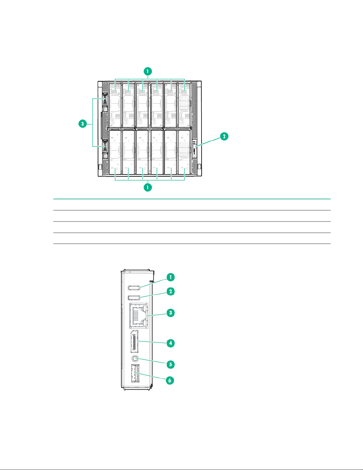
Component and LED identification
Frame front components and device bays
Item Description
1 Device bays—Compute modules and storage modules
2 Front panel—Provides access to the HPE Synergy console, via KVM or laptop.
3 Appliance bays
Front panel components
70 Component and LED identification
Page 71

Item Description Function
1
2
3
4
5
6
1
2
3
4
5
6
1 UID button Toggles the frame UID on or off.
2 Frame Health LED
Indicates the highest severity health status of all components
within the frame.
• Solid green—Normal operation
• Flashing amber—Warning
• Flashing red—Critical error
To resolve critical errors, connect to HPE OneView or to the
HPE Synergy Console.
3 Laptop port
Provides single laptop access to the frame link module using an
RJ-45 Ethernet 100BASE-TX connection.
4 Monitor port Provides connectivity for a monitor or an active monitor port
adapter to access the HPE Synergy Console.
5 Reset button
Provides two functions:
• Resets the Active frame link module - momentary press.
• Factory resets both frame link modules - press and hold
until UID LED blinks blue.
NOTE: The reset button does not reset any other component
in the frame.
6 USB Provides a connection for supported USB devices such as a
keyboard or mouse for HPE Synergy Console use. To connect
multiple devices, a USB hub (not included) is required.
Appliance module LEDs and components
Appliance module LEDs and components are the same for both an HPE Synergy Composer and an HPE
Synergy Image Streamer.
Component and LED identification 71
Page 72

Item Description Function
1 UID LED
Press the UID button to illuminate the blue locator LED.
• Solid blue—Illuminates to locate the appliance module.
• Flashing blue—Indicates appliance module firmware
update. Do not power off or remove appliance module when
the UID LED is flashing.
2 Health LED
3 Activity LED
4 Power LED
Indicates the health of the appliance module
• Solid green—Normal operation
• Flashing amber—Warning
• Flashing red—Critical error
The appliance Health LED provides health status of the
appliance. If the Health LED indicates a warning or a critical
error, connect to the Synergy console to troubleshoot.
Indicates which appliance module is active.
• Off—Indicates that the appliance module is the standby in a
Highly Available configuration or HPE OneView is in an error
state.
• Solid green—Indicates that the appliance module is active.
• Flashing green—Indicates that the reset button has been
pressed and held for greater than 10 seconds, which
initiates a reimaging of the appliance module. The active
LED does not continue to flash green during the reimaging
process.
Indicates power to the appliance
• Off—No power. Verify that the appliance module is fully
inserted into the frame link module.
• Flashing amber—Appliance module is initializing.
• Solid amber—Appliance module is powered off.
• Solid green—Appliance module is powered on.
5 Reset button
6 USB port USB 3.0 port for connecting a USB drive to flash a USB
Using an applicator such as a paper clip, press the recessed
button to reset the appliance module.
• Press and release—Resets the appliance module.
• Press and hold until activity LED is flashing green—Initiates
reimaging of the appliance module from files on the USB
flash drive plugged into the appliance module.
recovery image.
72 Component and LED identification
Page 73

Compute module LEDs and buttons
Item Description Status
1 UID LED
2 Health status LED
3 Mezzanine NIC status LED
Solid blue = Activated
Flashing blue (1 Hz/cycle per
sec) = Remote management or
firmware upgrade in progress
Off = Deactivated
Solid green = Normal
Flashing green (1 Hz/cycle per
sec) = HPE iLO is rebooting
Flashing amber = System
degraded
Flashing red (1 Hz/cycle per sec)
= System critical
Solid green= Link on any
Mezzanine NIC
Flashing green= Activity on any
Mezzanine NIC
Off = No link or activity on any
Mezzanine NIC
4 Power On/Standby button and
Solid green = System on
system power LED
Flashing green (1 Hz/cycle per
sec) = Performing power on
sequence
Solid amber = System in standby
Off = No power present
1
If all other LEDs are off, then no power is present to the compute module. If the health LED is flashing green while the
system power LED is off indicates that the Power On/Standby button service is initializing or that an iLO reboot is in
progress. Facility power is not present, power cord is not attached, no power supplies are installed, power supply
failure has occurred, or the power button cable is disconnected.
1
Component and LED identification 73
Page 74

System power LED definitions
1 2
The system power LED is located on the compute module Power On/Standby button.
System power LED Definition
Off No power present
Solid amber System is in standby
Flashing green (1 Hz/cycle per sec) Performing power on sequence
Solid green System on
NVDIMM LED identification
Item LED description LED color
1 Power LED Green
2 Function LED Blue
NVDIMM-N LED combinations
State Definition NVDIMM-N Power LED
0 AC power is on (12V rail) but the NVM
controller is not working or not ready.
1 AC power is on (12V rail) and the NVM
controller is ready.
2 AC power is off or the battery is off (12V
rail off).
3 AC power is on (12V rail) or the battery is
on (12V rail) and the NVDIMM-N is active
(backup and restore).
NVDIMM Function LED patterns
For the purpose of this table, the NVDIMM-N LED operates as follows:
NVDIMM-N Function
(green)
On Off
On On
Off Off
On Flashing
LED (blue)
• Solid indicates that the LED remains in the on state.
• Flashing indicates that the LED is on for 2 seconds and off for 1 second.
• Fast-flashing indicates that the LED is on for 300 ms and off for 300 ms.
74 Component and LED identification
Page 75

State Definition NVDIMM-N Function LED
0 The restore operation is in progress. Flashing
1 The restore operation is successful. Solid or On
2 Erase is in progress. Flashing
3 The erase operation is successful. Solid or On
4 The NVDIMM-N is armed, and the NVDIMM-N is in
normal operation.
5 The save operation is in progress. Flashing
6 The NVDIMM-N finished saving and battery is still
turned on (12 V still powered).
7 The NVDIMM-N has an internal error or a firmware
update is in progress. For more information about an
NVDIMM-N internal error, see the IML.
More information
Viewing the IML on page 93
Storage module LEDs
The front panel and LED layout shown in the following illustration is an example. Depending on your
specific model, the LEDs might be different.
Solid or On
Solid or On
Fast-flashing
Item LED Status Definition
1 Drawer status
Flashing green Drive drawer is open
Flashing amber Thermal warning, close
1
Solid green Drive drawer is closed
the drive drawer
Table Continued
Component and LED identification 75
Page 76
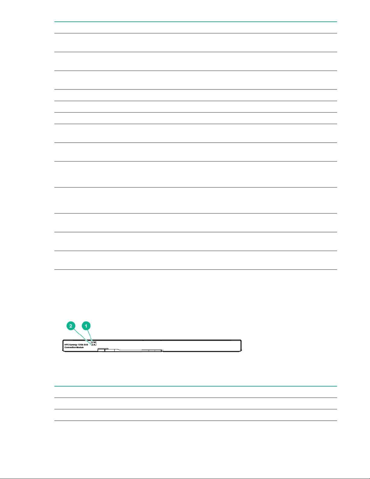
Item LED Status Definition
2 UID Solid blue One or more drives are
being located
Flashing blue Firmware flash in
progress
Off No drives are being
located
3 Health status Green Normal operation
Flashing amber Degraded condition
Flashing red Critical condition
4 Drive status (in priority
order)
Flashing amber One or more drives are
Flashing green One or more drives are
Solid green One or more drives are
Off No drives are configured
5 Drawer power Green Storage module is in
Off Storage module is not in
1
The drive drawer must be closed within five minutes after it is opened.
Solid amber One or more drives
failed
predicted to fail
rebuilding or
transforming
members of a logical
drive
by a RAID controller
use, do not remove
use, safe to remove
HPE Synergy 12Gb SAS Connection Module front panel LEDs
Item LED Status Definition
1 UID Off Normal
Solid blue Being identified
76 Component and LED identification
Table Continued
Page 77
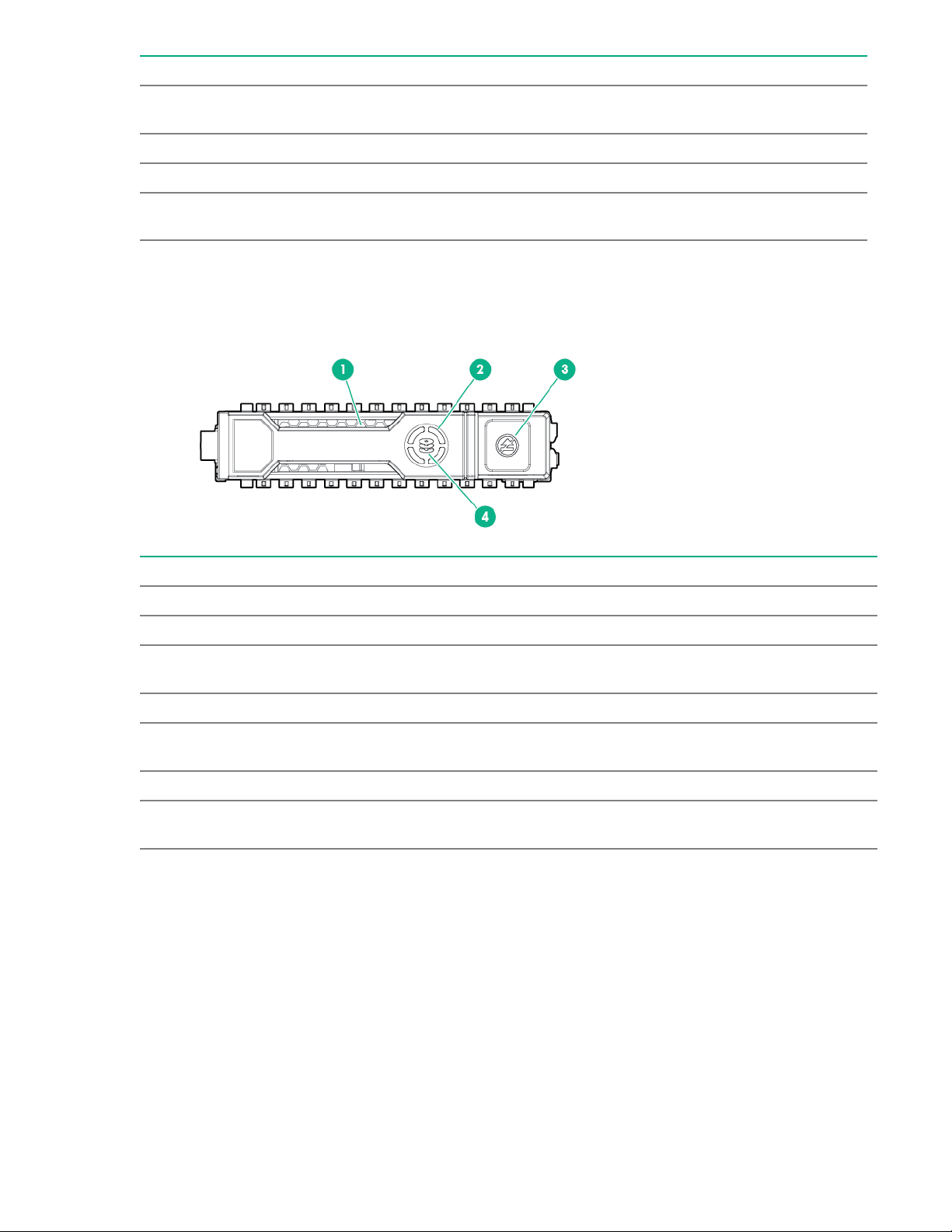
Item LED Status Definition
Flashing blue Firmware is being
2 Health Off Not powered up
Green Healthy
Flashing amber Error, there is a problem
Storage option LEDs, components, and guidelines
Hot-plug drive LED definitions
updated
with the module
Item LED Status Definition
1 Locate Solid blue The drive is being identified by a host application.
Flashing blue The drive carrier firmware is being updated or requires an update.
2 Activity
ring
Off No drive activity
3 Do not
remove
Off Removing the drive does not cause a logical drive to fail.
4 Drive
status
Rotating green Drive activity
Solid white Do not remove the drive. Removing the drive causes one or more of
the logical drives to fail.
Solid green The drive is a member of one or more logical drives.
Table Continued
Component and LED identification 77
Page 78

Item LED Status Definition
2 3 4
5
1
Flashing green
The drive is doing one of the following:
• Rebuilding
• Performing a RAID migration
• Performing a strip size migration
• Performing a capacity expansion
• Performing a logical drive extension
• Erasing
• Spare part activation
Flashing amber/
green
The drive is a member of one or more logical drives and predicts the
drive will fail.
Flashing amber The drive is not configured and predicts the drive will fail.
Solid amber The drive has failed.
Off The drive is not configured by a RAID controller or a spare drive.
SAS, SATA, and SSD drive guidelines
When adding drives to the compute module, observe the following general guidelines:
• Drives must be of the same capacity to provide the greatest storage space efficiency when drives are
grouped in the same drive array.
• Drives in the same logical volume must be of the same type. HPE SSA does not support mixing SAS,
SATA, and SSD drives in the same logical volume.
NVMe SSD LED definitions
The NVMe SSD is a PCIe bus device. A device attached to a PCIe bus cannot be removed without
allowing the device and bus to complete and cease the signal/traffic flow.
CAUTION: Do not remove an NVMe SSD from the drive bay while the Do not remove LED is
flashing. The Do not remove LED flashes to indicate that the device is still in use. Removing the
NVMe SSD before the device has completed and ceased signal/traffic flow can cause loss of data.
78 Component and LED identification
Page 79

Item LED Status Definition
1 Locate Solid blue The drive is being identified by a host application.
Flashing blue The drive carrier firmware is being updated or requires an update.
2 Activity
ring
Off No drive activity
3 Drive
status
Flashing green
Flashing amber/
Flashing amber The drive is not configured and predicts the drive will fail.
Solid amber The drive has failed.
Rotating green Drive activity
Solid green The drive is a member of one or more logical drives.
The drive is doing one of the following:
• Rebuilding
• Performing a RAID migration
• Performing a stripe size migration
• Performing a capacity expansion
• Performing a logical drive extension
• Erasing
The drive is a member of one or more logical drives and predicts the
green
drive will fail.
Off The drive is not configured by a RAID controller.
4 Do not
remove
Flashing white The drive ejection request is pending.
5 Power Solid green Do not remove the drive. The drive must be ejected from the PCIe bus
Solid white Do not remove the drive. The drive must be ejected from the PCIe bus
prior to removal.
Off The drive has been ejected.
prior to removal.
Flashing green The drive ejection request is pending.
Off The drive has been ejected.
Component and LED identification 79
Page 80
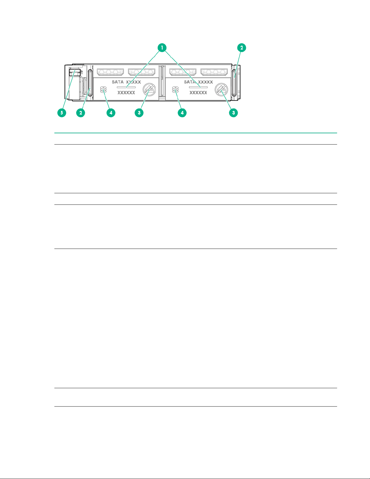
SFF flash adapter components and LED definitions
Item Component Description
1 Locate • Off—Normal
• Solid blue—The drive is being identified by a host application.
• Flashing blue—The drive firmware is being updated or
requires an update.
2 uFF drive ejection latch Removes the uFF drive when released.
3 Do not remove LED • Off—OK to remove the drive. Removing the drive does not
cause a logical drive to fail.
• Solid white—Do not remove the drive. Removing the drive
causes one or more of the logical drives to fail.
4 Drive status LED • Off—The drive is not configured by a RAID controller or a
spare drive.
• Solid green—The drive is a member of one or more logical
drives.
• Flashing green (4 Hz)—The drive is operating normally and
has activity.
• Flashing green (1 Hz)—The drive is rebuilding, erasing, or
performing a RAID migration, stripe size migration, capacity
expansion, logical drive extension, or spare activation.
• Flashing amber/green (1 Hz)—The drive is a member of one
or more logical drives that predicts the drive will fail.
• Solid amber—The drive has failed.
• Flashing amber (1 Hz)—The drive is not configured and
predicts the drive will fail.
5 Adapter ejection release latch
and handle
80 Component and LED identification
Removes the SFF flash adapter when released.
Page 81
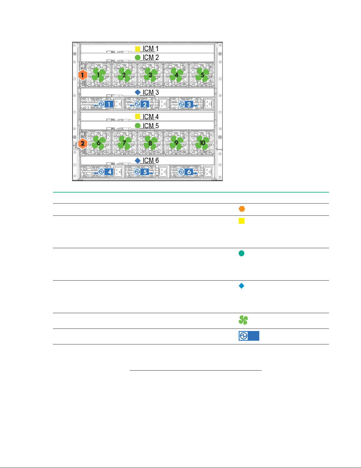
Frame rear component and bay numbering
Components Bays Labels
Frame link modules 1 and 2
Interconnect modules
These interconnect modules are
redundant pairs on fabric 1.
Interconnect modules
These interconnect modules are
redundant pairs on fabric 2.
Interconnect modules
These interconnect modules are
redundant pairs on fabric 3.
Fans 1 through 10
Power supplies 1 though 6
The arrow direction on each of the power supply icons indicates the recommended power routing to either
A-side or B-side. For more information about power cabling, see the HPE Synergy 12000 Frame Setup
and Installation Guide on the Hewlett Packard Enterprise Information Library.
1 and 4
2 and 5
3 and 8
Component and LED identification 81
Page 82

Frame link module components and LEDs
1
2
3
4
5
6
7
8
9
10
Item Description Function
1 MGMT port activity
LED
Reports MGMT port activity:
• Flashing green = Activity on the MGMT port
2 MGMT port
3 MGMT port
connectivity LED
4 Health LED
• Off = No activity on the MGMT port
A 10GBASE-T RJ45 connector that provides the following functions:
• Provides a management uplink to the management network.
• Provides a data connection to the data network when an Image
Streamer management appliance is installed in the frame.
• Automatically negotiates speed to 10GbE or 1GbE based on the
connection.
Reports MGMT port connectivity:
• Solid green = MGMT port is connected.
• Off = MGMT port is not connected.
Provides the health status of the frame link module.
• Solid green = Normal operation
• Flashing amber = Warning
• Flashing red = Critical error
If the Health LED indicates a warning or a critical error, connect to
HPE OneView or to the HPE Synergy Console for more information
and troubleshooting assistance.
Table Continued
82 Component and LED identification
Page 83

Item Description Function
5 UID button
Toggles the UID LED on or off.
• Solid blue = Activated
• Off = Deactivated
• Flashing blue = Firmware upgrade is in progress on the frame link
module.
Do not remove either frame link module while the UID LED is flashing.
6 USB
7 LINK port activity LED
8 LINK port
9 LINK port connectivity
LED
Allows connection to the frame using a supported USB device. Devices
include a keyboard or mouse for connecting to the HPE Synergy
Console. To connect multiple devices, a USB hub (not included) is
required.
Reports LINK port activity:
• Flashing green = Activity on the LINK port
• Off = No activity on the LINK port
A 10GBASE-T RJ45 connector that provides two functions:
• Provides high availability management network connectivity
between:
◦ LINK ports on two frame link modules in the same frame for a
single frame configuration
◦ Frame link modules in different frames as part of a management
network ring in a multiframe configuration
• Provides connectivity as part of a management network ring which
connects multiple frames for automatic discovery by HPE OneView.
Reports LINK port connectivity:
• Solid green = LINK port is connected.
10 Monitor port Allows connection to the frame using a monitor device or an active
Power supply LED
• Off = LINK port is not connected.
monitor port adapter.
Component and LED identification 83
Page 84

Power LED Condition
Off No input power to the power supply or power supply failure. Connect to
Solid green Normal operation
Flashing amber Warning. Connect to HPE OneView Hardware Setup to troubleshoot.
Fan LED
the HPE Synergy console and check for power supply error messages.
LED color Fan status
Solid green Normal operation
Flashing red Critical. Connect to HPE OneView Hardware Setup to troubleshoot.
Information pull tabs
Pull tabs on the Synergy frame link module front and rear provide system information.
84 Component and LED identification
Page 85

Item Description
1 The front pull tab (top left) has the frame link module product ID, serial number, and the
device bay numbering for the frame link module front bays.
2 The rear pull tab (top left) has the bay numbering for the frame link module rear bays.
3
The serial label pull tab is located on each compute module and contains the following
information:
• Product serial number
• iLO information
• QR code that points to mobile-friendly documentation
Component and LED identification 85
Page 86

Reports and logs
Overview
You might be asked to gather some of the following reports or logs when you contact Hewlett Packard
Enterprise:
• Active Health System log
• Integrated Management Log
• HPE SSA diagnostic tasks
• HPE Smart Storage Administrator Diagnostic Utility CLI reports
• HPS report
• sosreport and supportconfig
The AHSV allows you to view the Active Health System log and you can submit a support case.
Active Health System log
The Active Health System log is a single file that contains basic information required by Hewlett Packard
Enterprise support to analyze the system.
You can download the Active Health System log manually and send it to Hewlett Packard Enterprise. The
log can be downloaded using the following tools:
• Active Health System Viewer
• HPE iLO
• Intelligent Provisioning
• iLO RESTful API
• curl command-line tool
The Active Health System log can be captured using either offline or online methods.
Operating system Online server Offline server
Microsoft Windows HPE iLO web interface Intelligent Provisioning
Linux
VMware HPE iLO web interface Intelligent Provisioning
Other operating systems HPE iLO web interface Intelligent Provisioning
More information
Using AHSV to troubleshoot or open a support case on page 92
Intelligent Provisioning diagnostic tools on page 87
HPE iLO web interface
Intelligent Provisioning
86 Reports and logs
Page 87

Intelligent Provisioning diagnostic tools
Diagnostic tools are embedded on a NAND flash module that can be accessed by pressing F10 at POST
during compute module boot. For more information, see "Intelligent Provisioning software
documentation."
More information
Using AHSV to troubleshoot or open a support case on page 92
Intelligent Provisioning diagnostic tools on page 87
Active Health System Log download methods
You can use the following methods to download the Active Health System Log:
• iLO web interface—Download the log for a range of days or download the entire log from the Active
Health System Log page.
• iLO Service Port—Download the log by connecting a USB flash drive to the iLO Service Port on the
front of the server.
• cURL utility—Download the log by using the cURL command-line tool.
• Intelligent Provisioning—For instructions, see the Intelligent Provisioning user guide.
• iLO RESTful API and RESTful Interface Tool—For more information, see http://www.hpe.com/
support/restfulinterface/docs.
More information
Using AHSV to troubleshoot or open a support case on page 92
Intelligent Provisioning diagnostic tools on page 87
Active Health System Viewer
Active Health System Viewer (AHSV) is an online tool used to read, diagnose, and resolve server issues
quickly using AHS uploaded data. AHSV provides Hewlett Packard Enterprise recommended repair
actions based on experience and best practices. AHSV provides the ability to:
• Read server configuration information
• View Driver/Firmware inventory
• Review Event Logs
• Respond to Fault Detection Analytics alerts
• Open new and update existing support cases
More information
Using AHSV to troubleshoot or open a support case on page 92
Intelligent Provisioning diagnostic tools on page 87
Downloading the Active Health System Log for a date range
Procedure
1. Click Information in the navigation tree, and then click the Active Health System Log tab.
Reports and logs 87
Page 88

The Active Health System Log is inaccessible when it is being downloaded by Intelligent Provisioning,
the iLO Service Port, or any other method.
2. Enter the range of days to include in the log. The default value is seven days.
a. Click the From box.
A calendar is displayed.
b. Select the range start date on the calendar.
c. Click the To box.
A calendar is displayed.
d. Select the range end date on the calendar.
To reset the range to the default values, click .
3. Optional: Enter the following information to include in the downloaded file:
• Support case number (up to 14 characters)
• Contact name
• Phone number (up to 39 characters)
• Email address
• Company name
The contact information you provide will be treated in accordance with the Hewlett Packard Enterprise
privacy statement. This information is not written to the log data stored on the server.
4. Click Download.
5. Save the file.
6. If you have an open support case, you can email the log file to gsd_csc_case_mngmt@hpe.com.
Use the following convention for the email subject: CASE: <case number>.
Files that are larger than 25 MB must be compressed and uploaded to an FTP site. If needed, contact
Hewlett Packard Enterprise for FTP site information.
7. Optional: Upload the file to the Active Health System Viewer.
For more information, see http://www.hpe.com/servers/ahsv.
More information
Using AHSV to troubleshoot or open a support case on page 92
Intelligent Provisioning diagnostic tools on page 87
Downloading the entire Active Health System Log
It might take a long time to download the entire Active Health System Log. If you must upload the Active
Health System Log for a technical issue, Hewlett Packard Enterprise recommends downloading the log
for the specific range of dates in which the problem occurred.
Procedure
1. Click Information in the navigation tree, and then click the Active Health System Log tab.
88 Reports and logs
Page 89

The Active Health System Log is inaccessible when it is being downloaded by Intelligent Provisioning,
the iLO Service Port, or any other method.
2. Click Show Advanced Settings.
3. Optional: Enter the following information to include in the downloaded file:
• Support case number (up to 14 characters)
• Contact name
• Phone number (up to 39 characters)
• Email address
• Company name
The contact information that you provide will be treated in accordance with the Hewlett Packard
Enterprise privacy statement. This information is not written to the log data stored on the server.
4. Click Download Entire Log.
5. Save the file.
6. If you have an open support case, you can email the log file to gsd_csc_case_mngmt@hpe.com.
Use the following convention for the email subject: CASE: <case number>.
Files that are larger than 25 MB must be compressed and uploaded to an FTP site. If needed, contact
Hewlett Packard Enterprise for FTP site information.
7. Optional: Upload the file to the Active Health System Viewer.
For more information, see http://www.hpe.com/servers/ahsv.
More information
Using AHSV to troubleshoot or open a support case on page 92
Intelligent Provisioning diagnostic tools on page 87
Downloading the Active Health System Log by using cURL
iLO supports extracting the Active Health System Log with the cURL command-line tool.
Procedure
1. Install cURL.
2. You can download cURL from the following website: http://curl.haxx.se/.
3. Open a command window.
4. Enter a command similar to the following examples.
IMPORTANT: When you enter these commands, ensure that you do not use spaces or other
unsupported characters.
If required by your command-line environment, special characters such as the ampersand must
be preceded by the escape character. See the command-line environment documentation for
more information.
Reports and logs 89
Page 90

• To download the Active Health System Log for a range of dates:
curl "https://<iLO_IP_address>/ahsdata/ahs.ahs?from=<yyyy-mm-dd>&to=
<yyyy-mm-dd>" -k -v -u <username>:<password> -o <filename>.ahs
• To download the Active Health System Log for the last seven days, and add a Hewlett Packard
Enterprise support case number to the log header:
curl "https://<iLO_IP_address>/ahsdata/ahs.ahs?days=<number_of_days>
&case_no=<number>" -k -v -u <username>:<password> -o <filename>.ahs
• To download the Active Health System Log for the last seven days, and include a case number and
contact information:
curl "https://<iLO_IP_address>/ahsdata/ahs.ahs?days=<number_of_days>
&case_no=<number>&contact_name=<name>&phone=<phone_number>&email=
<email_address>&co_name=<company>" -k -v -u <username>:<password>
-o <filename>.ahs
• To download the entire Active Health System Log:
curl "https://<iLO_IP_address>/ahsdata/ahs.ahs?downloadAll=1" -k -v
-u <username>:<password> -o <filename>.ahs
5. The file is saved to the specified path.
6. Close the command window.
7. Optional: If you have an open support case, email the log file to gsd_csc_case_mngmt@hpe.com.
Use the following convention for the email subject: CASE: <case number>.
Files that are larger than 25 MB must be compressed and uploaded to an FTP site. If needed, contact
Hewlett Packard Enterprise for FTP site information.
8. Optional: Upload the file to the Active Health System Viewer.
For more information, see http://www.hpe.com/servers/ahsv.
More information
Using AHSV to troubleshoot or open a support case on page 92
Intelligent Provisioning diagnostic tools on page 87
cURL command usage with iLO
When you use cURL to extract the Active Health System log, the command components include the
following:
Options
<iLO IP address>
Specifies the iLO IP address.
from=<yyyy-mm-dd>&to=<yyyy-mm-dd>
Represents the start and end date of the range of dates to include in the log. Enter dates in the format
year-month-day, for example, 2017-07-29 for July 29, 2017.
days=<number of days>
Specifies that you want to download the log file for the last <number of days> from today's date.
90 Reports and logs
Page 91

downloadAll=1
Specifies that you want to download the entire log.
–k
Specifies that HTTPS warnings will be ignored.
–v
Specifies verbose output.
-u <username>:<password>
Specifies your iLO user account credentials.
–o <filename>.ahs
Specifies the output file name and path.
case_no=<HPE support case number>
Specifies a Hewlett Packard Enterprise support case number to add to the log header.
Options for adding contact information to the downloaded log
phone=<phone number>
Specifies a phone number to add to the log header.
email=<email address>
Specifies an email address to add to the log header.
contact_name=<contact name>
Specifies a contact name to add to the log header.
co_name=<company name>
Insert your company name in the log header.
More information
Using AHSV to troubleshoot or open a support case on page 92
Intelligent Provisioning diagnostic tools on page 87
Clearing the Active Health System Log
If the log file is corrupted, or if you want to clear and restart logging, clear the Active Health System Log.
Prerequisites
Configure iLO Settings privilege
Procedure
1. Click Information in the navigation tree, and then click the Active Health System Log tab.
The Active Health System Log is inaccessible when it is being downloaded by Intelligent Provisioning,
the iLO Service Port, or any other method.
2. Click Show Advanced Settings.
3. Scroll to the Clear Log section, and then click Clear.
4. When prompted to confirm the request, click Yes, clear.
iLO notifies you that the log is being cleared.
Reports and logs 91
Page 92

5. Reset iLO.
Resetting iLO is required because some Active Health System data is recorded to the log only during
iLO startup. Performing this step ensures that a complete set of data is available in the log.
6. Reboot the server.
Rebooting the server is required because some information, such as the operating system name and
version, is logged at server startup. Performing this step ensures that a complete set of data is
available in the log.
More information
Using AHSV to troubleshoot or open a support case on page 92
Intelligent Provisioning diagnostic tools on page 87
Downloading the AHS log through IP
For more information, see the Intelligent Provisioning user guide at
intelligentprovisioning/docs.
Procedure
1. Open Intelligent Provisioning [F10] at boot-up.
2. Click Perform Maintenance.
3. Click Active Health System download.
4. Leave the range as the default or as instructed by the Hewlett Packard Enterprise technician.
5. Click Download.
More information
Using AHSV to troubleshoot or open a support case on page 92
Intelligent Provisioning diagnostic tools on page 87
http://www.hpe.com/info/
Using AHSV to troubleshoot or open a support case
Hewlett Packard Enterprise has defined a set of rules to assist you with troubleshooting when you upload
an AHS log to Active Health System Viewer (AHSV), an online tool used to read, diagnose, and resolve
server issues.
For information on using the Active Health System Viewer, see the Active Health System Viewer User
Guide on the Hewlett Packard Enterprise website (http://www.hpe.com/support/ahsv-ug-en).
Procedure
1. Download the AHS log from the server.
For more information, see "Downloading the AHS log" in the Active Health System Viewer User Guide.
2. Log in to AHSV (http://www.hpe.com/servers/ahsv) with your HPE Passport credentials, and upload
the AHS log to AHSV.
3. Go to the AHSV dashboard to review errors.
4. Navigate to the Fault Detection Analytics page to identify additional error conditions and possible fixes.
Follow any recommended actions to clear the error.
5. If the issue persists, open a support case from the AHSV Dashboard.
92 Reports and logs
Page 93

For more information, see "Creating a support case" in the Active Health System Viewer User Guide.
More information
Using AHSV to troubleshoot or open a support case on page 92
Intelligent Provisioning diagnostic tools on page 87
Integrated Management Log
The IML records hundreds of events and stores them in an easy-to-view form. The IML timestamps each
event with one-minute granularity.
You can view recorded events in the IML in several ways, including the following:
• From within HPE SIM
• From within the UEFI System Utilities
• From within the Embedded UEFI shell
• From within operating system-specific IML viewers:
◦ For Windows: IML Viewer
◦ For Linux: IML Viewer Application
• From within the iLO web interface
• From within Insight Diagnostics
Viewing the IML
Procedure
1. Click Information in the navigation tree, and then click the Integrated Management Log tab.
2. Optional: Use the IML sort, search, and filter features to customize the log view.
The total number of recorded events is always displayed above the filter icon. When filters are applied,
the number of events that meet the filter criteria is displayed below the filter icon.
3. Optional: To view the event details pane, click an event.
Performing a Diagnostics task using HPE SSA
Procedure
1. Open HPE SSA.
2. Open the Diagnostics panel by doing one of the following:
• Select a device and click Diagnose in the quick navigation menu.
• Select an available device from the Home screen, and then click Diagnose under the available
options.
3. Select a report type.
For this example, use the Array Diagnostic Report selection.
4. Select Array Diagnostic Report.
Reports and logs 93
Page 94

The Actions panel for Array Diagnostic Report appears.
5. Click one of the task buttons:
• If you click View Diagnostic Report, the report appears. When you are finished viewing the
current report, click Close or Save.
• If you click Save Diagnostic Report, wait for the report to generate, and then click Close Report
or Save Report.
HPE Smart Storage Administrator Diagnostics Utility CLI
Installing the utility
Procedure
1. Browse to the HPE Smart Storage Administrator website.
2. Click Download software.
3. Select an OS.
4. Identify the preferred software and version, and then click Download.
5. Save, and then run, the executable file.
By default, the software installs at C:\Program Files\Smart Storage Administrator\.
Launching the utility in CLI mode
Procedure
1. Click Start>All Programs>Windows System>Smart Storage Administrator Diagnostics
Utility>Read Me
2. Open a command prompt as administrator.
3. Change directory (cd) to the location where ssaducli.exe is installed.
This directory is commonly C:\Program Files\Smart Storage Administrator\ssaducli\bin.
4. Do one of the following:
• Generate a diagnostic report with the following command:ssaducli -f adu-report.zip
• Generate a SmartSSD Wear Gauge report with the following command:ssaducli -ssd -f
ssd-report.zip
For more options, use the following command:
ssaducli -help
94 Reports and logs
Page 95

Diagnostic report procedures
Viewing the diagnostic report
Procedure
1. Launch the utility.
2. Browse to the .zip file you created using the utility.
3. Open the HTML file to view the report.
Identifying and viewing diagnostic report files
The diagnostic report output archive contains the following files:
• ADUReport.txt—Diagnostic report in text format
• ADUReport.xml—Diagnostic report in XML format
• ADUReportViewer.htm—HTML viewer for XML diagnostic report
• SlotX.txt (SlotX.old)—Controller serial output log
The serial output log file(s) are only available if the Smart Array SAS/SATA Event Notification Service
is installed and running.
Procedure
1. Extract ADUReportViewer.htm to a directory.
2. Open ADUReportViewer.htm in the browser.
SmartSSD Wear Gauge report procedures
Viewing the SmartSSD Wear Gauge report
Procedure
1. Launch the utility.
2. Browse to the .zip file you created using the utility.
3. Open the HTML file to view the report.
Identifying and viewing SmartSSD Wear Gauge report files
The SmartSSD Wear Gauge report output archive contains the following files:
• SmartSSDWearGaugeReport.txt—SmartSSD wear gauge report in text format
• SmartSSDWearGaugeReport.json—SmartSSD wear gauge report in JSON format
• SmartSSDWearGaugeReport.htm—HTML viewer for the JSON wear gauge report
Reports and logs 95
Page 96

Procedure
1. Extract the following files to a single directory:
• SmartSSDWearGaugeReport.json
• SmartSSDWearGaugeReport.htm
2. Open SmartSSDWearGaugeReport.htm in the browser.
HPS report
The HPS reports are used to capture critical operation and configuration information from Windows server
environments. The HPS report utility can be downloaded from the Hewlett Packard Enterprise website.
To start the report, run the executable file and the utility will save a cab file in the C:\WINDOWS
\HPSReports\Enhanced\Report directory.
Run this report before contacting Hewlett Packard Enterprise technical support and be prepared to
send the cab file.
More information
Accessing Hewlett Packard Enterprise Support on page 107
Linux reports
To assist in possible Linux installation issues on HPE servers, capture either the sosreport or
supportconfig before contacting Hewlett Packard Enterprise Support.
More information
Accessing Hewlett Packard Enterprise Support on page 107
96 Reports and logs
Page 97

Resources for troubleshooting
Online resources
Hewlett Packard Enterprise Support Center website
Troubleshooting tools and information, as well as the latest drivers and flash ROM images, are available
on the Hewlett Packard Enterprise website.
Hewlett Packard Enterprise Information Library
HPE ProLiant Server documentation is available in the Hewlett Packard Enterprise Information
Library.
Mobile-ready content
The HPE Synergy 12000 Frame includes QR codes that point directly to the mobile-ready documentation
from your mobile device.
To access the mobile-ready content, such as setup, installation, user, or troubleshooting documentation,
use your mobile device to scan the product-specific QR code.
Mobile QR code locations
Mobile QR codes are located on HPE Synergy components and pull tabs and provide quick and efficient
access to product specific content for the component. The QR codes takes you to a page that allows you
to browse to the online documentation by choosing an HPE Synergy component.
HPE Synergy documentation
The Hewlett Packard Enterprise Information Library (www.hpe.com/info/synergy-docs) is a task-based
repository. It includes installation instructions, user guides, maintenance and service guides, best
practices, and links to additional resources. Use this website to obtain the latest documentation, including:
• Learning about HPE Synergy technology
• Installing and cabling HPE Synergy
• Updating the HPE Synergy components
• Using and managing HPE Synergy
• Troubleshooting HPE Synergy
HPE Synergy Configuration and Compatibility Guide
The HPE Synergy Configuration and Compatibility Guide is in the Hewlett Packard Enterprise Information
Library (www.hpe.com/info/synergy-docs). It provides an overview of HPE Synergy management and
fabric architecture, detailed hardware component identification and configuration, and cabling examples.
HPE Synergy Frame Link Module User Guide
The HPE Synergy Frame Link Module User Guide is in the Hewlett Packard Enterprise Information
Library (www.hpe.com/info/synergy-docs). It outlines frame link module management, configuration,
and security.
Resources for troubleshooting 97
Page 98

HPE OneView User Guide and Help for HPE Synergy
The HPE OneView User Guide and Help for HPE Synergy is in the Hewlett Packard Enterprise
Information Library (www.hpe.com/info/synergy-docs). It describes resource features, planning tasks,
configuration quick start tasks, navigational tools for the graphical user interface, and more support and
reference information for HPE OneView.
HPE OneView Global Dashboard User Guide and Help
The HPE OneView Global Dashboard provides a unified view of health, alerting, and key resources
managed by HPE OneView across multiple platforms and data center sites. The HPE OneView Global
Dashboard User Guide is in the Hewlett Packard Enterprise Information Library (www.hpe.com/info/
synergy-docs). It provides instructions for installing, configuring, navigating, and troubleshooting the
HPE OneView Global Dashboard.
HPE Synergy Image Streamer User Guide
The HPE Synergy Image Streamer User Guide is in the Hewlett Packard Enterprise Information Library
www.hpe.com/info/synergy-docs). It describes the OS deployment process using Image Streamer,
(
features of Image Streamer, and purpose and life cycle of Image Streamer artifacts. It also includes
authentication, authorization, and troubleshooting information for Image Streamer.
HPE Synergy Image Streamer GitHub
The HPE Synergy Image Streamer GitHub repository (github.com/HewlettPackard) contains sample
artifacts and documentation on how to use the sample artifacts. It also contains technical white papers
explaining deployment steps that can be performed using Image Streamer.
HPE Synergy Software Overview Guide
The HPE Synergy Software Overview Guide is in the Hewlett Packard Enterprise Information Library
(www.hpe.com/info/synergy-docs). It provides detailed references and overviews of the various
software and configuration utilities to support HPE Synergy. The guide is task-based and covers the
documentation and resources for all supported software and configuration utilities available for:
• HPE Synergy setup and configuration
• OS deployment
• Firmware updates
• Troubleshooting
• Remote support
Best Practices for HPE Synergy Firmware and Driver Updates
The Best Practices for HPE Synergy Firmware and Driver Updates is in the Hewlett Packard Enterprise
Information Library (www.hpe.com/info/synergy-docs). It provides information on how to update the
firmware and recommended best practices to update firmware and drivers through HPE Synergy
Composer, which is powered by HPE OneView.
HPE OneView Support Matrix for HPE Synergy
The HPE OneView Support Matrix for HPE Synergy is in the Hewlett Packard Enterprise Information
Library (www.hpe.com/info/synergy-docs). It maintains the latest software and firmware requirements,
supported hardware, and configuration maximums for HPE OneView.
98 Resources for troubleshooting
Page 99

HPE Synergy Image Streamer Support Matrix
The HPE Synergy Image Streamer Support Matrix is in the Hewlett Packard Enterprise Information
Library (www.hpe.com/info/synergy-docs). It maintains the latest software and firmware requirements,
supported hardware, and configuration maximums for HPE Synergy Image Streamer.
HPE Synergy Glossary
The HPE Synergy Glossary, in the Hewlett Packard Enterprise Information Library (
synergy-docs), defines common terminology associated with HPE Synergy.
User guide
The compute module user guide provides component and LED identification, compute module setup,
cable routing, hardware options installation, and compute module specification information.
Product documentation can be accessed from the following locations:
• Hewlett Packard Enterprise Information Library — Select the product to narrow the list to fewer
documents.
• Hewlett Packard Enterprise Support Center website
Maintenance and service guide
The compute module maintenance and service guide provides a list of compute module spare parts,
compute module spare parts removal and replacement procedures, cable routing, component and LED
identification, and compute module specification information.
The compute module documentation can be accessed from the following locations:
• Hewlett Packard Enterprise Information Library — Select the product to narrow the list to fewer
documents.
www.hpe.com/info/
• Hewlett Packard Enterprise Support Center website
HPE iLO software documentation
For more information about HPE iLO, see the HPE iLO user guide on the Hewlett Packard Enterprise
website.
HPE Active Health System Viewer documentation
The HPE Active Health System Viewer is an online tool used to read, diagnose, and resolve server issues
using the AHS log.
For information on using the Active Health System viewer, see the HPE Active Health System Viewer
User Guide on the Hewlett Packard Enterprise website (http://www.hpe.com/support/ahsv-ug-en).
UEFI System Utilities documentation
For more information about UEFI System Utilities, see the UEFI System Utilities user documentation on
the Hewlett Packard Enterprise website (http://www.hpe.com/info/UEFI/docs).
Resources for troubleshooting 99
Page 100

Intelligent Provisioning software documentation
For more information about Intelligent Provisioning, see the Intelligent Provisioning user guide on the
Hewlett Packard Enterprise website. This user guide provides information on server configuration and
OS installation, performing maintenance tasks, troubleshooting, and other advanced topics.
White papers
White papers are electronic documentation on complex technical topics. Some white papers contain indepth details and procedures. Topics include Hewlett Packard Enterprise products, Hewlett Packard
Enterprise technology, OS, networking products, and performance. See one of the following websites:
• Hewlett Packard Enterprise Support Center
• Hewlett Packard Enterprise Information Library
Service notifications, advisories, and notices
Service notifications, advisories, and notices are available to provide more information about any known
issues with an HPE storage module. To locate service notifications, advisories or notices, search for your
product on the Hewlett Packard Enterprise website (http://www.hpe.com/support/hpesc). Use the filters
to narrow down the list of by documents type.
Subscription services
Receive support alerts, product support communications, driver updates, software releases, firmware
updates, and customer replaceable component information in your email by signing up on the Hewlett
Packard Enterprise website.
To change options for support alerts you already receive, click the link to sign in on the right.
HPE Pointnext Portfolio
HPE Pointnext delivers confidence, reduces risk, and helps customers realize agility and stability. Hewlett
Packard Enterprise helps customers succeed through Hybrid IT by simplifying and enriching the onpremise experience, informed by public cloud qualities and attributes.
Operational Support Services enable you to choose the right service level, length of coverage, and
response time to fit your business needs. For more information, see the Hewlett Packard Enterprise
website:
https://www.hpe.com/us/en/services/operational.html
Utilize the Advisory and Transformation Services in the following areas:
• Private or hybrid cloud computing
• Big data and mobility requirements
• Improving data center infrastructure
• Better use of server, storage, and networking technology
For more information, see the Hewlett Packard Enterprise website:
http://www.hpe.com/services/consulting
100 Resources for troubleshooting
 Loading...