

Page 1

User Service Guide
HP Integrity Superdome/sx2000 and HP 9000
Superdome/sx2000 Servers
HP Part Number: A9834-9001D_ed6
Published: September 2009
Edition: 6
Page 2

Legal Notices
© Copyright 2009 Hewlett-Packard Development Company, L.P. The information contained herein is subject to change without notice.
The only warranties for HP products and services are set forth in the express warranty statements accompanying such products and services.
Nothing herein should be construed as constituting an additional warranty. HP shall not be liable for technical or editorial errors or omissions
contained herein.
Intel and Itanium are trademarks or registered trademarks of Intel Corporation or its subsidiaries in the United States and other countries.
Microsoft and Windows are U.S. registered trademarks of Microsoft Corporation.
UNIX is a registered trademark of The Open Group.
Page 3

Table of Contents
About This Document.......................................................................................................13
Intended Audience................................................................................................................................13
Document Organization.......................................................................................................................13
Typographic Conventions.....................................................................................................................13
Related Information..............................................................................................................................14
Publishing History................................................................................................................................14
HP Encourages Your Comments..........................................................................................................15
1 Overview.......................................................................................................................17
Server History and Specifications.........................................................................................................17
Server Components...............................................................................................................................18
Power Subsystem..................................................................................................................................19
AC Power.........................................................................................................................................20
DC Power.........................................................................................................................................20
Power Sequencing............................................................................................................................21
Enabling 48 Volts.............................................................................................................................21
Cooling System.....................................................................................................................................21
Utilities Subsystem................................................................................................................................22
Platform Management.....................................................................................................................22
UGUY..............................................................................................................................................23
CLU Functionality...........................................................................................................................23
PM3 Functionality...........................................................................................................................23
System Clocks..................................................................................................................................24
Management Processor....................................................................................................................24
Compact Flash.................................................................................................................................25
HUCB...............................................................................................................................................25
Backplane..............................................................................................................................................26
Crossbar Chip..................................................................................................................................26
Switch Fabrics..................................................................................................................................27
Backplane Monitor and Control......................................................................................................27
I2C Bus Distribution........................................................................................................................27
Clock Subsystem..............................................................................................................................27
System Clock Distribution.........................................................................................................27
Hot-Swap Oscillator...................................................................................................................28
sx2000 RCS Module....................................................................................................................28
Cabinet ID........................................................................................................................................29
Cell ID..............................................................................................................................................29
Backplane Power Requirements and Power Distribution...............................................................29
CPUs and Memories.............................................................................................................................30
Cell Controller.................................................................................................................................31
Processor Interface...........................................................................................................................31
Processors........................................................................................................................................32
Cell Memory System.......................................................................................................................32
Memory Controller ....................................................................................................................33
DIMM Architecture....................................................................................................................33
Memory Interconnect.................................................................................................................33
Mixing Different Sized DIMMs..................................................................................................34
Memory Interleaving.................................................................................................................34
Memory Bank Attribute Table..............................................................................................34
Cell Map................................................................................................................................35
Table of Contents 3
Page 4

Link Interleaving...................................................................................................................35
Memory Error Protection...........................................................................................................35
DRAM Erasure...........................................................................................................................36
PDC Functional Changes.................................................................................................................36
Platform Dependent Hardware.......................................................................................................36
Reset.................................................................................................................................................37
Cell OL*...........................................................................................................................................37
I/O Subsystem.......................................................................................................................................37
PCI-X Backplane Functionality........................................................................................................38
SBA Chip CC-to-Ropes..............................................................................................................38
Ropes-to-PCI LBA Chip.............................................................................................................39
PCI Slots.....................................................................................................................................40
Mixed PCI-X and PCI Express I/O Chassis...........................................................................40
PCI Hot-Swap Support.........................................................................................................41
System Management Station................................................................................................................41
User Accounts..................................................................................................................................42
New Server Cabling..............................................................................................................................42
m-Link Cable...................................................................................................................................42
e-Link Cable.....................................................................................................................................42
Clock Cable......................................................................................................................................44
Firmware...............................................................................................................................................44
Itanium Firmware for HP Integrity Superdome/sx2000.................................................................44
Itanium System Firmware Functions.........................................................................................46
PA-RISC Firmware for HP 9000/sx2000 Servers..............................................................................46
PA-RISC System Firmware Functions........................................................................................47
Server Configurations...........................................................................................................................47
Server Errors.........................................................................................................................................48
2 System Specifications...................................................................................................49
Dimensions and Weights......................................................................................................................49
Component Dimensions..................................................................................................................49
Component Weights........................................................................................................................49
Shipping Dimensions and Weights.................................................................................................50
Electrical Specifications.........................................................................................................................50
Grounding.......................................................................................................................................51
Circuit Breaker.................................................................................................................................51
Power Options.................................................................................................................................51
System Power Requirements...........................................................................................................52
Component Power Requirements...................................................................................................53
IOX Cabinet Power Requirements...................................................................................................53
IOX Cabinet Power Cords...............................................................................................................53
Environmental Requirements...............................................................................................................54
Temperature and Humidity Specifications.....................................................................................54
Power Dissipation............................................................................................................................54
Acoustic Noise Specification...........................................................................................................56
Airflow.............................................................................................................................................56
3 Installing the System.....................................................................................................59
Introduction .........................................................................................................................................59
Communications Interference ........................................................................................................59
Electrostatic Discharge ...................................................................................................................59
Public Telecommunications Network Connection..........................................................................60
Unpacking and Inspecting the System.................................................................................................60
4 Table of Contents
Page 5

Verifying Site Preparation...............................................................................................................60
Gathering LAN Information......................................................................................................60
Verifying Electrical Requirements..............................................................................................60
Checking the Inventory...................................................................................................................60
Inspecting the Shipping Containers for Damage............................................................................61
Inspection Precautions...............................................................................................................62
Claims Procedures .....................................................................................................................62
Unpacking and Inspecting Hardware Components.......................................................................62
Tools Required............................................................................................................................63
Unpacking the Cabinet...............................................................................................................63
Unpacking the PDCA......................................................................................................................71
Returning Equipment......................................................................................................................71
Setting Up the System...........................................................................................................................72
Moving the System and Related Equipment to the Installation Site ..............................................72
Unpacking and Installing the Blower Housings and Blowers........................................................72
Attaching the Side Skins and Blower Side Bezels...........................................................................75
Attaching the Side Skins............................................................................................................75
Attaching the Blower Side Bezels...............................................................................................77
Attaching the Leveling Feet and Leveling the Cabinet...................................................................79
Installing the Front Door Bezels and the Front and Rear Blower Bezels .......................................79
Installing the Front Door Bezels.................................................................................................79
Installing the Rear Blower Bezel................................................................................................81
Installing the Front Blower Bezel...............................................................................................82
Wiring Check...................................................................................................................................83
Installing and Verifying the PDCA.................................................................................................84
Checking Voltage.............................................................................................................................88
Removing the EMI Panels...............................................................................................................89
Connecting the Cables.....................................................................................................................91
Routing the I/O Cables....................................................................................................................91
Installing the Support Management Station.........................................................................................93
Installing the SMS Support Shelf..........................................................................................................93
Connecting the SMS to the Superdome................................................................................................94
SMS Software and Superdome Firmware Downloading Procedure....................................................94
Configuring the Event Information Tools.............................................................................................95
Turning On Housekeeping Power........................................................................................................96
Connecting the MP to the Customer LAN...........................................................................................98
Connecting the MP to the Network.................................................................................................98
Setting the Customer IP Address....................................................................................................99
Booting and Verifying the System......................................................................................................101
Connecting to the MP....................................................................................................................101
Powering On the System 48 V Power Supply................................................................................104
Booting the HP Integrity Superdome/sx2000 to an EFI Shell........................................................104
Booting an HP 9000 sx2000 Server to BCH....................................................................................106
Verifying the System......................................................................................................................106
Running JET Software.........................................................................................................................108
Running JUST ...............................................................................................................................108
Power Cycling After Using JET.....................................................................................................109
Offline Diagnostic Environment.........................................................................................................109
Attaching the Rear Kick Plates............................................................................................................109
Performing a Visual Inspection and Completing the Installation......................................................110
Conducting a Post-Installation Check.................................................................................................112
4 Booting and Shutting Down the Operating System...............................................113
Operating Systems Supported on Cell-based HP Servers..................................................................113
Table of Contents 5
Page 6

System Boot Configuration Options...................................................................................................114
HP 9000 Boot Configuration Options............................................................................................114
HP Integrity Boot Configuration Options.....................................................................................114
Booting and Shutting Down HP-UX...................................................................................................118
HP-UX Support for Cell Local Memory........................................................................................118
Adding HP-UX to the Boot Options List.......................................................................................118
Booting HP-UX..............................................................................................................................119
Standard HP-UX Booting.........................................................................................................120
Single-User Mode HP-UX Booting...........................................................................................123
LVM-Maintenance Mode HP-UX Booting...............................................................................126
Shutting Down HP-UX..................................................................................................................127
Booting and Shutting Down HP OpenVMS I64.................................................................................128
HP OpenVMS I64 Support for Cell Local Memory.......................................................................129
Adding HP OpenVMS to the Boot Options List............................................................................129
Booting HP OpenVMS...................................................................................................................131
Shutting Down HP OpenVMS.......................................................................................................132
Booting and Shutting Down Microsoft Windows..............................................................................133
Microsoft Windows Support for Cell Local Memory....................................................................133
Adding Microsoft Windows to the Boot Options List...................................................................134
Booting Microsoft Windows..........................................................................................................135
Shutting Down Microsoft Windows..............................................................................................137
Booting and Shutting Down Linux.....................................................................................................138
Linux Support for Cell Local Memory..........................................................................................138
Adding Linux to the Boot Options List.........................................................................................139
Booting Red Hat Enterprise Linux................................................................................................140
Booting SuSE Linux Enterprise Server .........................................................................................141
Shutting Down Linux....................................................................................................................142
A sx2000 LEDs..............................................................................................................145
B Management Processor Commands........................................................................149
BO Command .....................................................................................................................................149
CA Command.....................................................................................................................................149
CC Command......................................................................................................................................150
CP Command......................................................................................................................................151
DATE Command.................................................................................................................................152
DC Command.....................................................................................................................................152
DF Command......................................................................................................................................153
DI Command.......................................................................................................................................154
DL Command......................................................................................................................................155
EL Command......................................................................................................................................155
HE Command.....................................................................................................................................156
ID Command.......................................................................................................................................157
IO Command.......................................................................................................................................158
IT Command.......................................................................................................................................159
LC Command......................................................................................................................................159
LS Command.......................................................................................................................................160
MA Command....................................................................................................................................160
ND Command.....................................................................................................................................161
PD Command......................................................................................................................................161
PE Command......................................................................................................................................162
PS Command.......................................................................................................................................163
RE Command......................................................................................................................................164
6 Table of Contents
Page 7

RL Command......................................................................................................................................165
RR Command......................................................................................................................................166
RS Command......................................................................................................................................166
SA Command......................................................................................................................................167
SO Command......................................................................................................................................167
SYSREV Command.............................................................................................................................168
TC Command......................................................................................................................................169
TE Command......................................................................................................................................169
VM Command.....................................................................................................................................170
WHO Command.................................................................................................................................170
XD Command.....................................................................................................................................171
C Powering the System On and Off ...........................................................................173
Shutting Down the System.................................................................................................................173
Checking System Configuration....................................................................................................173
Shutting Down the Operating System...........................................................................................175
Preparing the Partitions for Shutdown..........................................................................................176
Powering Off the System...............................................................................................................177
Turning On Housekeeping Power......................................................................................................178
Powering On the System Using the PE Command.............................................................................180
D Templates....................................................................................................................183
Templates............................................................................................................................................183
Equipment Footprint Templates....................................................................................................185
Computer Room Layout Plan........................................................................................................185
Index...............................................................................................................................197
Table of Contents 7
Page 8

List of Figures
1-1 Superdome History.......................................................................................................................17
1-2 Superdome Cabinet Components.................................................................................................19
1-3 UGUY............................................................................................................................................23
1-4 Management Processor.................................................................................................................25
1-5 HUCB.............................................................................................................................................26
1-6 HSO and RCS Locations................................................................................................................29
1-7 Backplane Power Supply Module.................................................................................................30
1-8 Backplane (Rear View)..................................................................................................................30
1-9 Cell Board......................................................................................................................................31
1-10 Cell Memory..................................................................................................................................33
1-11 PCI-X I/O Rope Mapping..............................................................................................................39
1-12 PCIe I/O Rope Mapping................................................................................................................41
1-13 e-Link Cable...................................................................................................................................43
1-14 Backplane Cables...........................................................................................................................44
1-15 Itanium Firmware Interfaces.........................................................................................................45
1-16 PA-RISC Firmware Interfaces........................................................................................................47
2-1 PDCA Locations............................................................................................................................52
2-2 Airflow Diagram...........................................................................................................................57
3-1 Normal Tilt Indicator....................................................................................................................61
3-2 Abnormal Tilt Indicator ................................................................................................................62
3-3 Front of Cabinet Container............................................................................................................64
3-4 Cutting the Polystrap Bands..........................................................................................................64
3-5 Removing the Ramps from the Pallet............................................................................................65
3-6 Power Supply Mounting Screws Location....................................................................................66
3-7 I/O Chassis Mounting Screws.......................................................................................................66
3-8 Shipping Strap Location................................................................................................................68
3-9 Removing the Mounting Brackets.................................................................................................69
3-10 Positioning the Ramps...................................................................................................................70
3-11 Rolling the Cabinet Down the Ramp............................................................................................70
3-12 Blower Housing Frame..................................................................................................................72
3-13 Removing Protective Cardboard from the Housing.....................................................................73
3-14 Installing the Rear Blower Housing..............................................................................................73
3-15 Installing the Front Blower Housing.............................................................................................74
3-16 Installing the Blowers....................................................................................................................75
3-17 Attaching the Rear Side Skin.........................................................................................................76
3-18 Attaching the Front Side Skins......................................................................................................77
3-19 Attaching the Side Bezels..............................................................................................................78
3-20 Attaching the Leveling Feet...........................................................................................................79
3-21 Installing the Lower Front Door Assembly...................................................................................80
3-22 Installing the Upper Front Door Assembly...................................................................................81
3-23 Installing the Rear Blower Bezel....................................................................................................82
3-24 Installing the Front Blower Bezel..................................................................................................83
3-25 PDCA Assembly for Options 6 and 7............................................................................................85
3-26 A 4-Wire Connector.......................................................................................................................85
3-27 A 5-Wire Connector.......................................................................................................................86
3-28 Installing the PDCA.......................................................................................................................86
3-29 Checking PDCA Test Points (5-Wire)............................................................................................87
3-30 Wall Receptacle Pinouts................................................................................................................88
3-31 Power Supply Indicator LED........................................................................................................89
3-32 Removing Front EMI Panel Screw................................................................................................90
3-33 Removing the Back EMI Panel......................................................................................................90
3-34 Cable Labeling...............................................................................................................................91
8 List of Figures
Page 9

3-35 Routing I/O Cables........................................................................................................................92
3-36 Front Panel with HKP and Present LEDs......................................................................................97
3-37 BPS LEDs.......................................................................................................................................98
3-38 MP LAN Connection Location......................................................................................................99
3-39 LAN Configuration Screen..........................................................................................................100
3-40 The ls Command Screen..............................................................................................................101
3-41 Logging In....................................................................................................................................102
3-42 Main MP Menu............................................................................................................................102
3-43 MP Command Option.................................................................................................................103
3-44 MP Virtual Front Panel................................................................................................................103
3-45 Example of Partition State—Cabinet Not Powered Up...............................................................103
3-46 MP Console Option.....................................................................................................................104
3-47 HP Integrity Superdome/sx2000 EFI Boot Manager...................................................................105
3-48 EFI Shell Prompt..........................................................................................................................105
3-49 HP Integrity Superdome/sx2000 Partitions at System Firmware Console..................................106
3-50 Power Status First Window.........................................................................................................107
3-51 Power Status Window.................................................................................................................107
3-52 Power Status Showing State of UGUY LEDs ..............................................................................108
3-53 Attaching Rear Kick Plates..........................................................................................................110
3-54 Cell Board Ejectors.......................................................................................................................111
3-55 Front EMI Panel Flange and Cabinet Holes................................................................................111
3-56 Reinstalling the Back EMI Panel..................................................................................................112
A-1 Utilities ........................................................................................................................................147
A-2 PDH Status..................................................................................................................................147
C-1 Connecting to the Host................................................................................................................173
C-2 Main MP Menu............................................................................................................................173
C-3 Checking for Other Users............................................................................................................174
C-4 Checking Current System Configuration....................................................................................174
C-5 MP Virtual Front Panel................................................................................................................174
C-6 Example of Partition State...........................................................................................................175
C-7 Partition Consoles Menu.............................................................................................................175
C-8 Entering the rr Command...........................................................................................................176
C-9 Using the de -s Command........................................................................................................177
C-10 Power Entity Command..............................................................................................................177
C-11 Power Status First Window.........................................................................................................178
C-12 Power Status Second Window.....................................................................................................178
C-13 Front Panel Display with Housekeeping (HKP) Power and Present LEDs On..........................179
C-14 BPS LEDs.....................................................................................................................................180
C-15 Power Entity Command..............................................................................................................181
C-16 Power Status First Window.........................................................................................................181
C-17 Power Status Window.................................................................................................................182
D-1 Cable Cutouts and Caster Locations...........................................................................................183
D-2 SD16 and SD32 Space Requirements...........................................................................................184
D-3 SD64 Space Requirements...........................................................................................................185
D-4 Computer Floor Template...........................................................................................................186
D-5 Computer Floor Template...........................................................................................................187
D-6 Computer Floor Template...........................................................................................................188
D-7 Computer Floor Template...........................................................................................................189
D-8 Computer Floor Template...........................................................................................................190
D-9 SD32, SD64, and IOX Cabinet Templates....................................................................................191
D-10 SD32, SD64, and IOX Cabinet Templates....................................................................................192
D-11 SD32, SD64, and IOX Cabinet Templates....................................................................................193
D-12 SD32, SD64, and IOX Cabinet Templates....................................................................................194
D-13 SD32, SD64, and IOX Cabinet Templates....................................................................................195
D-14 SD32, SD64, and IOX Cabinet Templates....................................................................................196
9
Page 10

List of Tables
1-1 HSO LED Status Indicator Meaning.............................................................................................28
1-2 Supported Processors and Minimum Firmware Versions............................................................32
1-3 SMS Lifecycles...............................................................................................................................42
2-1 Server Component Dimensions....................................................................................................49
2-2 I/O Expansion Cabinet Component Dimensions..........................................................................49
2-3 System Component Weights.........................................................................................................49
2-4 IOX Cabinet Weights.....................................................................................................................50
2-5 Miscellaneous Dimensions and Weights.......................................................................................50
2-6 Available Power Options...............................................................................................................51
2-7 Option 6 and 7 Specifics................................................................................................................51
2-8 Power Requirements (Without SMS)............................................................................................52
2-9 Component Power Requirements (Without SMS)........................................................................53
2-10 I/O Expansion Cabinet Power Requirements (Without SMS).......................................................53
2-11 I/O Expansion Cabinet Component Power Requirements............................................................53
2-12 I/O Expansion Cabinet ac Power Cords........................................................................................54
2-13 Operational Physical Environment Requirements........................................................................54
2-14 Nonoperational Physical Environment Requirements.................................................................54
2-15 HP Integrity Superdome/sx2000 Dual-Core CPU Configurations...............................................55
2-16 HP Integrity Superdome/sx2000 Single-Core CPU Configurations.............................................55
2-17 Physical Environmental Specifications.........................................................................................57
3-1 Available Power Options...............................................................................................................71
3-2 Power Cord Option 6 and 7 Details...............................................................................................71
3-3 4- and 5-Wire Voltage Ranges.......................................................................................................87
A-1 Front Panel LEDs.........................................................................................................................145
A-2 Power and OL* LEDs...................................................................................................................146
A-3 OL* LED States............................................................................................................................147
A-4 PDH Status and Power Good LED States....................................................................................148
10 List of Tables
Page 11

List of Examples
3-1 Directory Example.........................................................................................................................95
3-2 Directory Example.........................................................................................................................95
4-1 Single-User HP-UX Boot..............................................................................................................124
B-1 BO command...............................................................................................................................149
B-2 CA Command..............................................................................................................................150
B-3 CC Command..............................................................................................................................151
B-4 CP Command..............................................................................................................................152
B-5 DATE Command.........................................................................................................................152
B-6 DC Command..............................................................................................................................153
B-7 DF Command..............................................................................................................................154
B-8 DI Command...............................................................................................................................155
B-9 DL Command..............................................................................................................................155
B-10 EL Command...............................................................................................................................156
B-11 HE Command..............................................................................................................................157
B-12 ID Command...............................................................................................................................158
B-13 Example: .....................................................................................................................................159
B-14 IT Command................................................................................................................................159
B-15 LC Command..............................................................................................................................160
B-16 LS Command...............................................................................................................................160
B-17 MP Main Menu............................................................................................................................161
B-18 ND Command.............................................................................................................................161
B-19 PD Command..............................................................................................................................162
B-20 PE Command for a Compute Cabinet.........................................................................................163
B-21 PS Command...............................................................................................................................164
B-22 Re-key lock for partition 3...........................................................................................................166
B-23 RR Command..............................................................................................................................166
B-24 RS Command...............................................................................................................................167
B-25 SA Command..............................................................................................................................167
B-26 SO Command..............................................................................................................................168
B-27 SYSREV Command......................................................................................................................169
B-28 TC Command..............................................................................................................................169
B-29 TE Command...............................................................................................................................170
B-30 VM Command.............................................................................................................................170
B-31 WHO Command..........................................................................................................................171
B-32 XD Command..............................................................................................................................172
11
Page 12

12
Page 13

About This Document
This document contains the system overview, system-specific parameters, installation procedures
of the system, operating system specifics, and procedures for components in the system.
Intended Audience
This document is intended for HP trained Customer Support Consultants.
Document Organization
This document is organized as follows:
Chapter 1 This chapter presents an historical view of the Superdome server family,
describes the various server components, and describes how the server
components function together.
Chapter 2 This chapter contains the dimensions and weights for the server and various
components. Electricalspecifications, environmental requirements, and templates
are also included.
Chapter 3 This chapter describes how to unpack and inspect the system, set up the system,
connect the MP to the customer LAN, and how to complete the installation.
Chapter 4 This chapter describes how to boot and shut down the server operating system
(OS) for each OS supported.
Appendix A This appendix contains tables that describe the various LED states for the front
panel, power and OL* states, and OL* states for I/O chassis cards.
Appendix B This appendix provides a summary for each management processor (MP)
command. Screen output is provided for each command so you can see the
results of the command.
Appendix C This appendix provides procedures to power off and power on the system when
the removal and replacement of a component requires it.
Appendix D This appendix contains templates for cable cutouts and caster locations; SD16,
SD32, SD64, and I/O expansion cabinets; and the computer room floor.
Typographic Conventions
The following typographic conventions are used in this document.
WARNING! Lists requirements that you must meet to avoid personal injury.
CAUTION: Provides information required to avoid losing data or to avoid losing system
functionality.
IMPORTANT: Provides essential information to explain a concept or to complete a task.
NOTE: Highlights useful information such as restrictions, recommendations, or important
details about HP product features.
• Commands and options are represented using this font.
• Text that you type exactly as shown is represented using this font.
Intended Audience 13
Page 14

• Text to be replaced with text that you supply is represented using this font.
Example: “Enter the ls -l filename command” means you must replace filename with your
own text.
• Keyboard keys and graphical interface items (such as buttons, tabs, and menu items)
are represented using this font.
Examples: The Control key, the OK button, the General tab, the Options menu.
• Menu —> Submenu represents a menu selection you can perform.
Example: “Select the Partition —> Create Partition action” means you must select the
Create Partition menu item from the Partition menu.
• Example screen output is represented using this font.
Related Information
Further informationon HP server hardware management, Microsoft® Windows®, and diagnostic
support tools are available through the following website links.
Website for HP Technical Documentation Thefollowing link is the main website for HP technical
documentation. This site offers comprehensive information about HP products available for free.
See http://docs.hp.com.
Server Hardware Information The following link is the systems hardware section of the
docs.hp.com website. It provides HP nPartition server hardware management information,
including information on site preparation, installation, and so on. See http://docs.hp.com/hpux/
hw/.
Diagnostics and Event Monitoring: Hardware Support Tools The following link contains
comprehensive information about HP hardware support tools, including online and offline
diagnostics and event monitoring tools. This website has manuals, tutorials, FAQs, and other
reference material. See http://docs.hp.com/hpux/diag.
Website for HP Technical Support The following link is the HP IT resource center website and
provides comprehensive support information for IT professionals on a wide variety of topics,
including software, hardware, and networking. See http://us-sup port2.external.hp.com.
Publishing History
The document printing date and edition number indicate the document’s current edition and
are included in the following table. The printing date will change when a new edition is produced.
Document updatesmay beissued between editions tocorrect errorsor documentproduct changes.
The latest version of this document is available on line at:
docs.hp.com.
March 2006. . . . . . . . . . . . . . . . . . . . . . . . . . . . . . . . . . . . . . . . . . . . . . . . . . . . . . . .First Edition
September 2006. . . . . . . . . . . . . . . . . . . . . . . . . . . . . . . . . . . . . . . . . . . . . . . . . . . . . . . .Second Edition
February 2007. . . . . . . . . . . . . . . . . . . . . . . . . . . . . . . . . . . . . . . . . . . . . . . . . . . . . . . .Third Edition
November 2007. . . . . . . . . . . . . . . . . . . . . . . . . . . . . . . . . . . . . . . . . . . . . . . . . . . . . . . .Fourth Edition
March 2009. . . . . . . . . . . . . . . . . . . . . . . . . . . . . . . . . . . . . . . . . . . . . . . . . . . . . . . .Fifth Edition
September 2009. . . . . . . . . . . . . . . . . . . . . . . . . . . . . . . . . . . . . . . . . . . . . . . . . . . . . . . .Sixth Edition
14
Page 15
HP Encourages Your Comments
HP welcomes your feedback on this publication. Direct your comments to http://docs.hp.com/
en/feedback.html and note that you will not receive an immediate reply. All comments are
appreciated.
HP Encourages Your Comments 15
Page 16

16
Page 17
1 Overview
Server History and Specifications
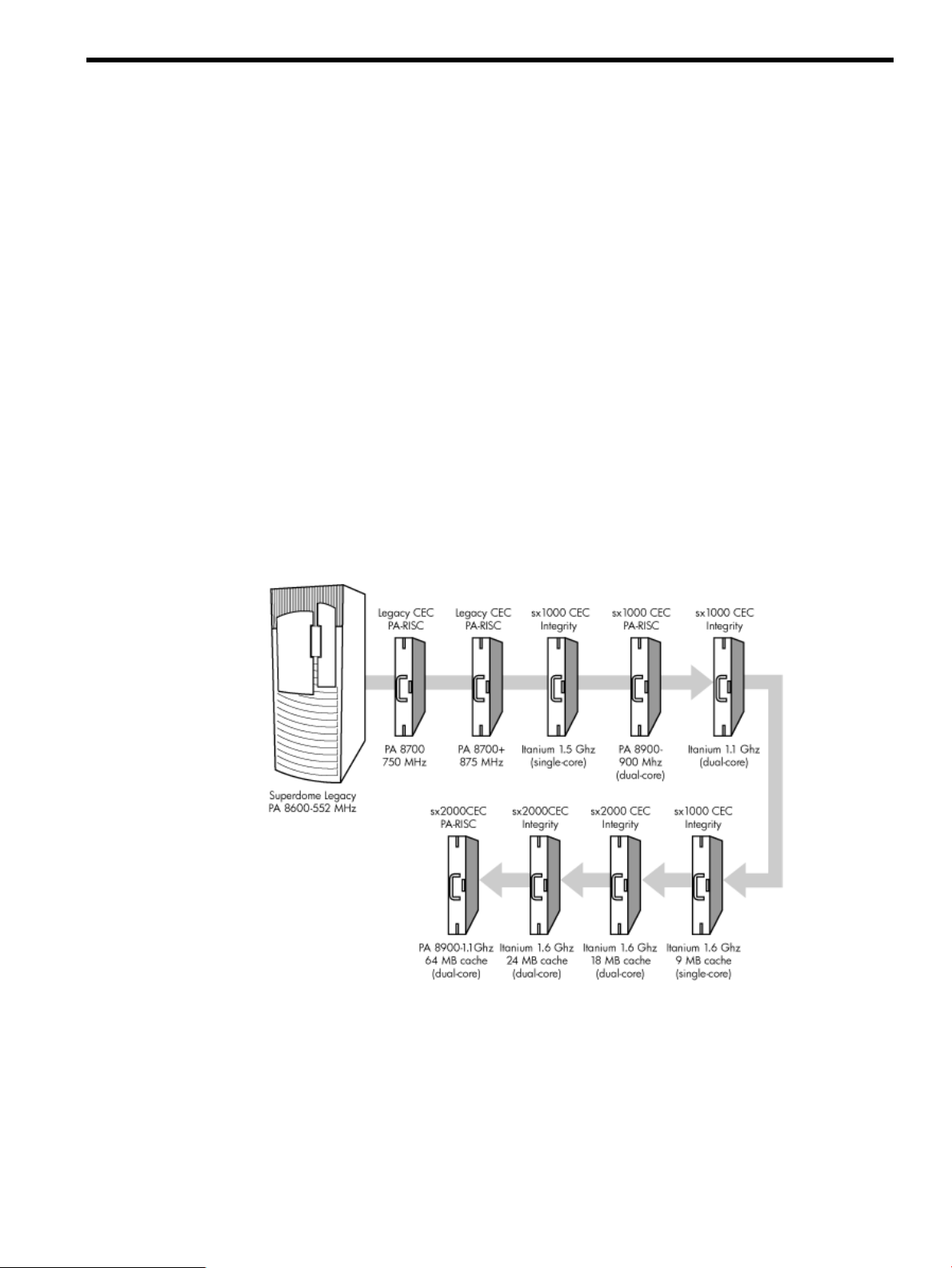
Superdome was introduced as the new platform architecture for high-end HP servers between
the years 2000 and 2004. Superdome represented the first collaborative hardware design effort
between traditional HP and Convex technologies. Superdome was designed to replace T- and
V-Class servers and to prepare for the transition from PA-RISC to Intel® Itanium® processors.
The new design enabled the ability of running different operating systems on the same server.
The design also included several new, high-availability features. Initially, Superdomewas released
with the legacy core electronics complex (CEC) and a 552 MHz PA-8600 processor. The Legacy
CEC supported two additional speeds; a 750 MHz PA-8700 followed by an 875 MHz PA-8700
processor.
The HP Integrity server project consisted of four projects based on the sx1000 CEC chipset and
the Integrity cell boards. The first release was the sx1000 chipset, Integrity cell boards, Itanium
firmware and a 1.2 MHz Intel® processor. This release included PCI-X and PCI I/O mixes. The
Integrity systems were compatible with the legacy Superdome IOX.
The second release, based on the sx1000 CEC, included Integrity cell boards, but used PA-RISC
firmware, and a dual-core PA-RISC processor. The release also included a 2 GB DIMM and a
new HP-UX version. Components such as processors, processor power pods, memory, firmware,
and operating system all changed for this release.
Figure 1-1 Superdome History
The third release, also based on the sx1000 chipset, included the Integrity cell boards, Itanium
firmware, and a 1.5 MHz Itanium CPU. The CPU module consisted of a dual-core processor with
a new cache controller. The firmware allowed for mixed cells within a system. All three DIMM
sizes were supported. Firmware and operating system changes were minor compared to their
earlier versions.
The fourth and final release is the HP super scalable sx2000 processor chipset. It is also based on
the new CEC that supports up to 128 PA-RISC or Itanium processors. It is the last generation of
Superdome servers to support the PA-RISC family of processors. Modifications to the server
components include:
Server History and Specifications 17
Page 18

• the new CEC chipset
• board changes including cell board
• system backplane
• I/O backplane
• associated power boards
• interconnect
• a redundant, hot-swappable clock source
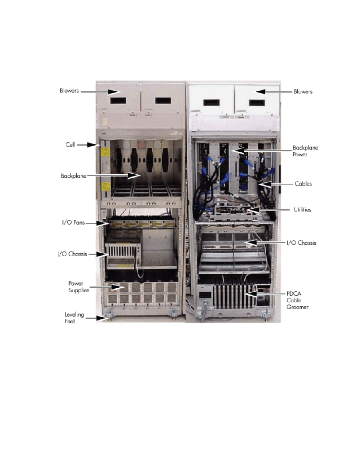
Server Components
A Superdome system consists of the following types of cabinet assemblies:
• Minimum ofone Superdomeleft-side cabinet.The Superdomecabinet containsthe processors,
the memory, and the core devices of the system. They also house the system's PCI cards.
Systems can include both left and right cabinet assemblies containing a left or right backplane
(SD64) respectively.
• One or more HP Rack System/E cabinets. These rack cabinets are used to hold the system
peripheral devices such as disk drives.
• Optionally, one or more I/O expansion cabinets (Rack System/E). An I/O expansion cabinet
is required when a customer requires more PCI cards than can be accommodated in the
Superdome cabinets.
The width of the cabinet assemblies accommodates moving them through standard-sized
doorways. The intake air to the main (cell) card cage is filtered. This air filter is removable for
cleaning and replacement while the system is fully operational.
A status display is located on the outside of the front and rear doors of each cabinet. This feature
enables you to determine the basic status of each cabinet without opening any cabinet doors.
The Superdome is a cell-based system. Cells communicate with others utilizing the crossbar on
the backplane. Every cell has its own I/O interface, which can be connected to one 12-slot I/O
card cage using two System Bus Adapter (SBA) link cables. Not all SBA links are connected by
default, due to a physical limitation of four I/O card cages per cabinet or node. In addition to
these components, each system consists of a power subsystem and a utility subsystem. Three
types of Superdome are available:
• SD16
• SD32
• SD64, a two-cabinet system with single-CPU cell board sockets
The SD## represents the maximum number of available CPU sockets.
An SD16 contains the following components:
• Up to four cell boards
• Four I/O card cages
• Five I/O fans
• Four system cooling fans
• Four bulk power supplies (BPS)
• Two power distribution control assemblies (PDCA)
Two backplane N+1 power supplies provide power to the SD16. The four cell boards are connected
to one pair of crossbar chips (XBC). The backplane of an SD16 is the same as a backplane of an
SD32. On the HUCB utility PCB is a switch set to TYPE= 1.
An SD32 has up to eight cell boards. All eight cell boards are connected to two pairs of XBCs.
The SD32 backplane is designed for a system upgrade to an SD64. On an SD32, four of the eight
connectors use U-Turn cables. The U-Turn cables double the number of links and the bandwidth
between the XBCs and are recommended to achieve best performance. An SD64 has up to 16 cell
boards and requires two cabinets. All 16 cell boards are connected to four pairs of XBCs. The
18 Overview
Page 19
SD64 consists of left backplane and right backplane cabinets, which are connected using 12
m-Link cables.
When the PA-RISC dual-core or the Itanium dual-core processors are used, the CPU counts are
doubled by the use of the dual-die processors, as supported on the Intel® Itanium® cell boards.
Up to 128 processors can be supported.
Figure 1-2 Superdome Cabinet Components
Power Subsystem
The power subsystem consists of the following components:
• One or two PDCAs
• One Front End Power Supply (FEPS)
• Up to six BPS
• One power board per cell
• An HIOB power system
• Backplane power bricks
• Power monitor (PM) on the Universal Glob of Utilities (UGUY)
• Local power monitors (LPM) on the cell, the HIOB, and the backplanes
Power Subsystem 19
Page 20

AC Power
The ac power system includes the PDCA, one FEPS, and up to six BPS.
The FEPS is a modular, 2n+2 shelf assembly power system that can consume up to 17 KVA of
power from ac sources. The purpose of the FEPS chassis is to provide interconnect, signal and
voltage busing between the PDCAs and BPSs, between the BPSs and utility subsystem, and
between the BPS and the system power architecture. The FEPS subsystem comprisesthree distinct
modular assemblies: six BPS, two PDCAs, and one FEPS chassis.
At least one 3-phase PDCA per Superdome cabinet is required. For redundancy, you can use a
second PDCA. The purpose of the PDCA is to receive a single 3-phase input and output three
1-phase outputs with a voltage range of 200 to 240 volts regardless of the ac source type. The
PDCA also provides a convenience disconnect switch/circuit breaker for service, test points, and
voltage present LED indicators. The PDCA is offered as a 4-wire or a 5-wire PDCA device.
Separate PDCAs (PDCA-0 and PDCA-1) can be connected to 4-wire and 5-wire input source
simultaneously as long as the PDCA internal wiring matches the wiring configuration of the ac
source.
The 4-wire PDCA is used in a phase to phase voltage range of 200 to 240 volts at 50/60 Hz. This
PDCA is rated for a maximum input current of 44 Amps per phase. The ac input power line to
the PDCA is connected with power plugs or is hardwired. When using power plugs, use a power
cord [OLFLEX 190 (PN 6008044) four conductor 6-AWG (16 mm), 600 V, 60 Amp, 90˚C, UL and
CSA approved, conforms to CE directives GN/YW ground wire].
When installing cables in locations that have been designated as “air handling spaces” (under
raised flooring or overhead space used for air supply and air return), advise the customer to
specify the use of data cables that contain a plenum rating. Data cables with this rating have been
certified for FLAMESPREAD and TOXICITY (low smoke emissions). Power cables do not carry
a plenum rating, they carry a data processing (DP) rating. Power cables installed in air handling
spaces should be specified with a DP rating. Details on the various levels of the DP rating system
are found in the National Electric Code (NEC) under Article 645.
The following recommend plugs for the 4-wire PDCA:
• In-line connector: Mennekes ME 460C9, 3-phase, 4-wire, 60 Amp, 250 V, UL approved, color
• Panel-mount receptacle: Mennekes ME 460R9, 3-phase, 4-wire, 60 Amp, 250 V, UL approved,
The 5 wire PDCA is used in a phase-to-neutral voltage range of 200 to 240 V ac 50/60Hz. This
PDCA is rated for a maximum input current of 24 Amps per phase. The ac input power line to
the PDCA is connected with power plugs or is hardwired. When using power plugs, a power
cord [five conductors, 10-AWG (6 mm), 450/475 V, 32 Amps, <HAR< European wire cordage,
GN/YW ground wire]. Alternatively the customer can provide the power plug including the
power cord and the receptacle. Recommended plugs are as follows:
• Inline connector: Mennekes ME532C6-16, 3-phase, 5-wire, 32 Amps, 450/475 V, VDE certified,
• Panel-mount receptacle: Mennekes ME532R6-1276, 3-phase, 5-wire, 32 Amp, 450/475 V, VDE
• FUSE per phase: 25 Amp (valid for Germany).
blue, IEC309-1 grounded at 9:00 o'clock.
color blue, IEC309-1 grounded at 9:00 o'clock.
color red, IEC309-1, IEC309-2, grounded at 6:00 o'clock.
certified, color red, IEC309-1, IEC309-2, grounded at 6:00 o'clock.
DC Power
Each power supply output provides 48 V dc up to 60 A (2.88 kVA) and 5.3 V dc housekeeping.
Normally an SD32 Superdome cabinet contains six BPS independent from the installed number
of cells and I/O. An SD16 normally has four BPS installed.
20 Overview
Page 21

Power Sequencing
The power on sequence is as follows:
1. When the main power circuit breaker is turned on, the housekeeping (HKP) voltage turns
on first and provides 5.3 V dc tothe UGUY, ManagementProcessor (MP), system backplane,
cells, and all HIOB. Each BPS provides 5.3 V.
2. When HKP voltage is on the MP performs the following steps:
a. De-asserts the Reset and begins to boot SBC.
b. Loads VxWorks from flash (can be viewed from the local port).
c. Completes the SBC, single board computer hub (SBCH) power-on self-test (POST)
begins, and LED start activity appears.
d. Loads firmware from Compact Flash to RAM.
e. SBCH POST completes. The heartbeat light blinks. USB LEDs turn on later.
f. CLU POST and PM POST immediately after power on.
3. After MP POST completes, the MP configures the system.
4. The CLU POST completes.
5. When PM POST completes, the system takes several steps.
6. When the MP finishes the system configuration, it becomes operational and completes
several tasks.
7. When the PDHC POST completes, it becomes operational and completes its tasks.
When the MP, CLU, and PM PDHC POST completes, utilities entities run their main loops.
Enabling 48 Volts
The PM must enable +48 V first , but it must obtain permission from the MP. To enable 48 V, the
transition cabinet power switch must be moved from OFF to ON. Alternatively you can use the
MP Command pe if the power switch is already ON. If the switch is ON, the cabinet wakes up
from Power on Reset).
If the PM has permission, it sends a PS_CTL_L signal to the FEPS. Then the BPS enables +48 V
converters, which send +48 V to the backplane, I/O chassis, HUCB, cells, fans, and blowers. Once
the +48 V is enabled, it is cabled to the backplane, cells, and I/O chassis.
Cooling System
The Superdome has four blowers and five I/O fans per cabinet. These components are all
hot-swappable. All have LEDs indicating their current status. Temperature monitoring occurs
for the following:
• Inlet air for temperature increases above normal
• BPS for temperature increases above normal
• The I/O power board over temperature signal is monitored
The inlet air sensor is on the main cabinet, located near the bottom of cell 1 front. The inlet air
sensor and the BPS sensors are monitored by the power monitor 3 (PM3) on the UGUY, and the
I/O power board sensors are monitored by the CLU on the UGUY.
The PM controls and monitors the speed of groups of N+1 redundant fans. In a CPU cabinet, fan
group 0 consists of the four main blowers and fan group 1 consists of the five I/O fans. In an I/O
Expansion (IOX) cabinet, fan groups 0–3 consist of four I/O fans and fan group 4 consists of two
management subsystem fans. All fans are expected to be populated at all times with the exception
of the OLR of a failed fan.
The main blowers feature a variable speed control. The blowers operate at full speed; available
circuitry can reduce the normal operating speed. All of the I/O fans and managed fans run at
one speed.
Cooling System 21
Page 22

One minute after setting the main blower fan Reference to the desired speed or powering on the
cabinet, the PM uses the tach select register to cycle through each fan and measure its speed.
When a fan is selected, Timer 1 is used in counter mode to count the pulses on port T1 over a
period of one second. If the frequency does not equal the expected frequency plus some margin
of error, the fan is considered to have failed and is subtracted from the working fan count.
If the failure causes a transition to N- I/O or main fans in a CPU cabinet, the cabinet is immediately
powered off. If the failure causes a transition to N- I/O fans in an IOX cabinet, the I/O backplanes
contained in the I/O Chassis Enclosure (ICE) containing that fan groupare immediately powered
off.
Only inlet temperature increases are monitored by HP-UX; all other high temperature increase
chassis codes do not activate the envd daemon to act as configured in the /etc/envd.conf
file. The PM monitors ambient inlet temperature. The PM polls an analog-to-digital converter to
read the current ambient temperature. The temperature falls into one of four ranges: Normal,
OverTempLow, OverTempMid, or OverTempHigh. The following state codes describe the actions
taken based on the various temperature state transitions:
OTL_THRESHOLD = 32C -----> Send error code PDC_IPR_OLT
OTM_THRESHOLD = 38C ----> Send error code PDC_INT_OTM
OTH_THRESHOLD = 40C -----> Shut down 48 V
NOTE: In an IOX cabinet, the thresholds are set two degrees higher to compensate for the fact
that the cabinet sensor is mounted in a hot spot.
Utilities Subsystem
The Superdome utilities subsystem is comprised of a number of hardware and firmware
components located throughout the Superdome system.
Platform Management
The sx2000 platform management subsystem consists of a number of hardware and firmware
components located throughout the sx2000 system. The sx2000 uses the sx1000 platform
management components, with firmware changes to support new functionality.
The following list describes the major hardware components of the platform management
subsystem and the changes required for the sx2000:
The PDH microcontroller is located on each cell PDH daughtercard assembly. It provides
communication between the management firmware, the PDH space, and the USB bus. The
microcontroller represents a change from the prior implementation, Intel® 80C251 processes, to
a more powerful 16-bit microcontroller. This microcontroller change enables the PDH
daughtercard design to be compatible across all three new CEC platforms. It also enables the
extra processing power to be used to move the console UARTs into PDH memory space located
on the cell, eliminating the sx1000 core I/O (CIO) card.
The UGUY on Superdome contains the PM, the CLU, and the system clock source circuitry.
The CLU circuitry on the UGUY assembly provides cabinet-level cable interconnect for backplane,
I/O card cage utility signal communication, and scan support.
The PM circuitry on the UGUY assembly monitors and controls the 48 V dc, the cabinet
environment (ambient temperature and fans), and controls power to the entities (cells and I/O
bays).
The MP is a single board computer (SBC) that controls the console (local and remote), the front
panel display and its redirection on the console, maintains logs for the event IDs, coordinates
messages between devices, and performs other service processor functions.
The SBCH board provides USB hubs into the cabinet from an upstream hub or the MP.
22 Overview
Page 23
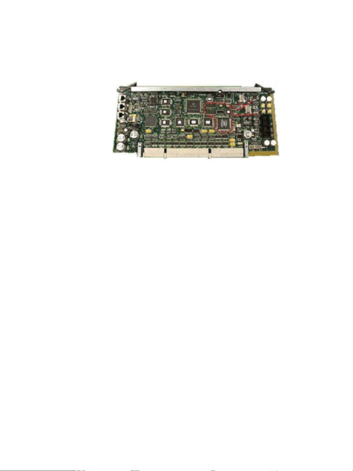
UGUY
Every cabinet contains one UGUY. See (Figure 1-3). The UGUY plugs into the HUCB. It is not
hot-swappable. Its MP microprocessor controls power monitor functions, executing the Power
Monitor 3 (PM3) firmware and the CLU firmware.
Figure 1-3 UGUY
CLU Functionality
The CLU collects and reports the configuration information for itself, the main backplane, I/O
backplanes, and the SUB/HUB. Each of these boards has a configuration EEPROM containing
FRU IDs,revision information, and for the main backplane and I/O backplanes, maximum power
requirements in the fully configured, fully loaded states. These EEPROMs are powered by
housekeeping power (HKP) and areaccessible to SARG from anI2C bus. The power requirement
information is sent to the PM3 automatically when HKP is applied or when a new entity is
plugged in. The configuration information is sent to the SUB in response to a get_config
command.
The CLU gathers the following information over its five I2C buses:
• Board revision information is contained in the board's configuration EEPROM for the UGUY
board, the SBCH board, the main backplane, the main backplane power boards (HBPB), the
I/O backplane (HIOB), and the I/O backplane power boards (IOPB).
• Power requirements from the configuration EEPROM for the main backplane (HLSB or
HRSB) and the I/O backplanes. This information is sent to the PM3 processor so it can
calculate cabinet power requirements.
• Power control and status interface. Another function of the UGUY is to use the power_ good
signals to drive the power on sequence.
• Reset control which includes a reset for each I/O backplane, a main backplane cabinet reset,
TRST - JTAG reset for all JTAG scan chains in the entire cabinet, a system clock control
margin control, nominal or high margin and a clock source selection and internal or external
OL* LED control.
• Status LEDs for the SBA cable OL*, the cell OL*, the I/O backplane OL*, the JTAG scan
control, the three scan chains per cell, the three scan chains per I/O backplane, and the three
scan chains on the main backplane.
PM3 Functionality
The PM3 performs the following functions:
Utilities Subsystem 23
Page 24

1. FEPS control and monitoring.
Superdome has six BPS and the UGUY sends 5V to the BPS for use by the fault collection
circuitry.
2. Fan control and monitoring.
In addition to the blowers, there are five I/O system fans above and between the I/O bays.
These fans run at full speed all the time. There is no fan speed signal.
3. Cabinet mode and cabinet number fan out.
The surface mount dip switch on the HUCB (UGUY backplane) is used to configure a
Superdome cabinet for normal use or as an SD16 cabinet. Use the 16-position thumb switch
on the UGUY to set the cabinet number. Numbers 0-7 are for CPU-oriented cabinets and
numbers 8-15 are for I/O-only cabinets.
4. Local Power Monitor (LPM) interfaces. Each big board (cell board, I/ O backplane, and main
backplane) contains logic that controls conversion of 48 V to lower voltages. The PM3
interfaces to the LPM with the board-present input signal to the PM3 and the power-enable
output signal from the PM3.
5. Front and rear panel board control.
System Clocks
The sx2000 system clock differs from the sx1000 system clock in that the system clocks are only
supplied from the backplane and to the backplane crossbar ASICs and the cell boards. There is
no distribution of the system clocks to the I/O backplanes. Instead, independent local clock
distribution is provided on the I/O backplane. The system clocks are not provided by the PM3
on sx2000 servers. The sx2000 system clock source resides on the system backplane.
Management Processor
The MP is comprised of two PCBs, the SBC and the SBCH.The MP is a hot-swappable unit
powered by +5 V HKP that holds the MP configuration parameters in compact flash and the
error and activity logs and the complex identification information or complex profile in battery
backed NVRAM. It also provides the USB network controller (MP bus). Each complex has one
MP per complex. It cannot be set up for redundancy. However, it is not a single point of failure
for the complex because it can be hot-swapped. If the MP fails, the complex can still boot and
function. However, the following utility functions are lost until the MP can be replaced:
• Processing and storing log entries (chassis codes)
• Console functions to every partition
• OL* functions
• VFP and system alert notification
• Connection to the MP for maintenance, either locally or remotely
• Diagnostics (ODE and scan)
24 Overview
Page 25

Figure 1-4 Management Processor
The SBCH provides the physical and electrical interface to the SBC, the fanning out of the USB
to internal and external subsystems, and a LAN 10/100BT ethernet connection. It plugs into the
HUCB and is hot-swappable. Every CPU cabinet contains one SBCH board, but only one SBCH
contains an SBC board used as the MP for the complex. The remaining SBCH boards act as USB
hubs.
The SBC board is an embedded computer running system utility board (SUB) firmware. It is the
core of the MP. It plugs into the SBCH board through a PC104 interface. The SBC provides the
following external interfaces to the utility subsystem:
• LAN (10/100BT ethernet) for customer console access
• RS232 port for local console access for manufacturing and field support personnel
The modem function is not included on the SBC and must be external to the cabinet.
Compact Flash
The Compact Flash is a PCMCIA-style memory card that plugs into the SBC board. It stores the
MP firmware and the customer's MP configuration parameters. The parameters stored in the
compact flash are as follows:
• Network configurations for both the public and private LANs
• User name and password combinations for logging in to the MP
• Baud rates for the serial ports
• Paging parameters for a specified alert level
• Configurable system alert parameters
HUCB
The HUCB, shown in Figure 1-5, is the backplane of the utility subsystem. It provides cable
distribution for all the utility signals except the clocks. It also provides the customer LAN interface
and serial ports. The support management station (SMS) connects to the HUCB. The system type
switch is located on the HUCB. This board has no active circuits. It is not hot-swappable.
Utilities Subsystem 25
Page 26

Figure 1-5 HUCB
Backplane
The system backplane assembly fabric provides the following functionality in an sx2000 system:
• Interfaces the CLU subsystem to the system backplane and cell modules
• Houses the system crossbar switch fabrics and cell modules
• Provides switch fabric interconnect between multiple cabinets
• Generates system clock sources
• Performs redundant system clock source switching
• Distributes the system clock to crossbar chips and cell modules
• Distributes HKP to cell modules
• Terminates I/O cables to cell modules
The backplane supports up to eight cells, interconnected by the crossbar links. A sustained total
bandwidth of 25.5 GB is provided to each cell. Each cell connects to three individual XBC ASICs.
This connection enables a single chip crossing when a cell communicates with another cell in its
four-cell group. When transferring data between cells in different groups, two crossbar links
compensate for the resultant multiple chip crossings. This topology also provides for switch
fabric redundancy
Dual rack/backplane systems contain two identical backplanes. These backplanes use 12
high-speed interface cables as interconnects instead of the flex cable interface previously employed
for the legacy Superdome crossbar. The sustainable bisection bandwidth between cabinets is 72
GB/s at a link speed of 2.1 GT/s.
Crossbar Chip
The crossbar fabrics in the sx2000 are implemented using the XBC crossbar chip. Each XBC is a
non-bit-sliced, eight-portnon-blocking crossbar that can communicate with the CC or XBC ASICs.
Each of the eight ports is full duplex, capable of transmitting and receiving independent packets
simultaneously. Each port consists of 20 channels of IBM's HSS technology. Eighteen channels
are used for packet data. One channel is used for horizontal link parity, and one channel is a
spare. The HSS channels can run from 2.0- 3.2 GT/s. At 3.0 GT/s, each port provides 8.5 GB/s of
sustainable bidirectional data bandwidth.
Like the CC and the SBA, XBC implements link-level retry to recover from intermittent link
errors. XBC can also replace a hard-failed channel with the spare channel during the retry process,
which guarantees continued reliable operation in the event of a broken channel, or single or
multibit intermittent errors.
XBC supports enhanced security between hard partitions by providing write protection on key
CSRs. Without protection, CSRs such as the routing tables can be modified by a rogue OS, causing
other hard partitions in the system to crash. To prevent this, key CSRs in XBC can only be modified
by packets with the Secure bit set. This bit is set by the CC, based on a register that is set only by
26 Overview
Page 27

a hard cell reset, which causes secure firmware to be entered. This bit is cleared by secure firmware
before passing control to an OS.
Switch Fabrics
The system backplane houses the switch fabric that connects to each of the cell modules. The
crossbar switch is implemented by a three-link-per-cell topology: three independent switch
fabrics connected in parallel. This topology provides switch fabric redundancy in the crossbar
switch. The backplane crossbar can be extended to an additional crossbar in a second backplane
for a dual backplane configuration. It connects through a high-speed cable interface to the second
backplane. This 12-cable high-speed interface replaces the flex cable interface previously used
on the Superdome system.
Backplane Monitor and Control
The backplane implements the following monitor and control functions:.
• Backplane detect and enable functions to and from the CLU
• Backplane LED controls from the CLU
• Backplane JTAG distribution and chains
• Cabinet ID from the CLU
• Reset and power manager FPGA (RPM) and JTAG interface and header for external
programming
• XBC reset, configuration and control
• IIC bus distribution to and from the CLU
• Clock subsystem monitor and control
• Power supply monitor and control
• Cell detect, power monitor, reset and enable to and from the CLU
• JTAG and USB data distribution to and from each cell module
• Cell ID to each cell module
• OSP FPGA functionality
I2C Bus Distribution
The sx2000 system I2C bus extends to the Superdome backplane (SDBP) assembly through a
cable connected from the CLU subsystem. This cable connects from J17 on the CLU to J64 on the
SDBP. The clock and data signals on this cable are buffered through I2C bus extenders on the
CLU and on the backplane.
The I2C bus is routed to an I2C multiplexer on the backplane where the bus is isolated into four
bus segments. Three bus segments are dedicated to connections to the three RPMs. The remaining
segment is used to daisy-chain the remaining addressable devices on the bus. Each bus segment
is addressed through a port on the I2C multiplexer.
Clock Subsystem
The backplane houses two hot-swap oscillator (HSO) modules. Each HSO board generates a
system clock that feeds into the backplane. Each HSO output is routed to the redundant clock
source (RCS) module. The RCS module accepts input from the two HSO modules and produces
a single system clock, which is distributed on the backplane to all cell modules and XBC ASICs.
System Clock Distribution
The system components that receive the system clock are the eight cell boards that plug into to
the backplane and the six XBC on the system backplane. Two backplane clock power detectors
(one for each 8-way sine clock power splitter) are on the RCS. The backplane power detector sits
at the end of the clock tree and measures the amplitude of the clock from the RCS to determine
Backplane 27
Page 28

if it is providing a signal of the correct amplitude to the cell boards and XBCs. Its output is also
an alarm signal to the RPM FPGA.
System clocks can originate from these input sources:
• the single-ended external clock input MCX connector
• the 280 MHz margin oscillator on the redundant clock source (RCS) board
• one of the 266.667 MHz oscillators on one of the HSO modules
The source selection is determined either by firmware or by logic in the RCS.
The clock source has alarm signals to indicate the following health status conditions to the cabinet
management subsystem:
• Loss of power and loss of clock for each of the clock oscillator boards
• Loss of clock output to the backplanes
The sx2000 clock system differs from the sx1000 clock system in that the system clocks are only
supplied to the backplane crossbar ASICs and the cell boards. System clocks are not distributed
to the I/O backplanes. Instead, independent local clock distribution is provided on the I/O
backplane.
Hot-Swap Oscillator
Two hot-swappable clock oscillators combine the outputs of both oscillators to form an N+1
redundant fault tolerant clock source. The resultant clock source drives clocks over connector
and cable interfaces to the system backplanes.
The HSO board contains a 266.667 MHz PECL oscillator. The output from this oscillator drives
a 266.667 MHz band-pass SAW filter that drives a monolithic IC power amplifier. The output of
the power amplifier is a 266.667 sine wave clock that goes to the RCS. The module also has two
LEDs, one green and one yellow, that are visible through the module handle.Table 1-1 describes
the HSO LEDs. The electrical signal that controls the LEDs is driven by the RCS.
Table 1-1 HSO LED Status Indicator Meaning
sx2000 RCS Module
The sx2000 RCS module supplies clocks to the Superdome sx2000 backplane, communicates
clock alarms to the RPM, and accepts control input from the RPM. It has an I2C EEPROM on the
module so that the firmware can inventory the module on system power on.
The RCS supplies 16 copies of the sine wave system clock to the sx2000 system backplane. Eight
copies go to the eight cell boards, six copies go to the six XBCs on the system backplane, and two
copies to the backplane clock power detector.
In normal operation, the RCS selects one of the two HSOs as the source of clocks for the platform.
The HSO selected depends on whether the HSO is plugged into the backplane and on whether
it has a valid output level. This selection is overridden if there is a connection from the clock
input MCX connector on the master backplane. Figure 1-6 shows the locations of the HSOs and
RCS on the backplane.
MeaningYellow LEDGreen LED
OffOn
OnOff
Module OK. HSO is producing a clock of the correct amplitude and frequency
and is plugged into its connector.
Module needsattention. HSO isnot producing aclock of thecorrect amplitude
or frequency, but it is plugged into its connector.
Module power is off.OffOff
28 Overview
Page 29
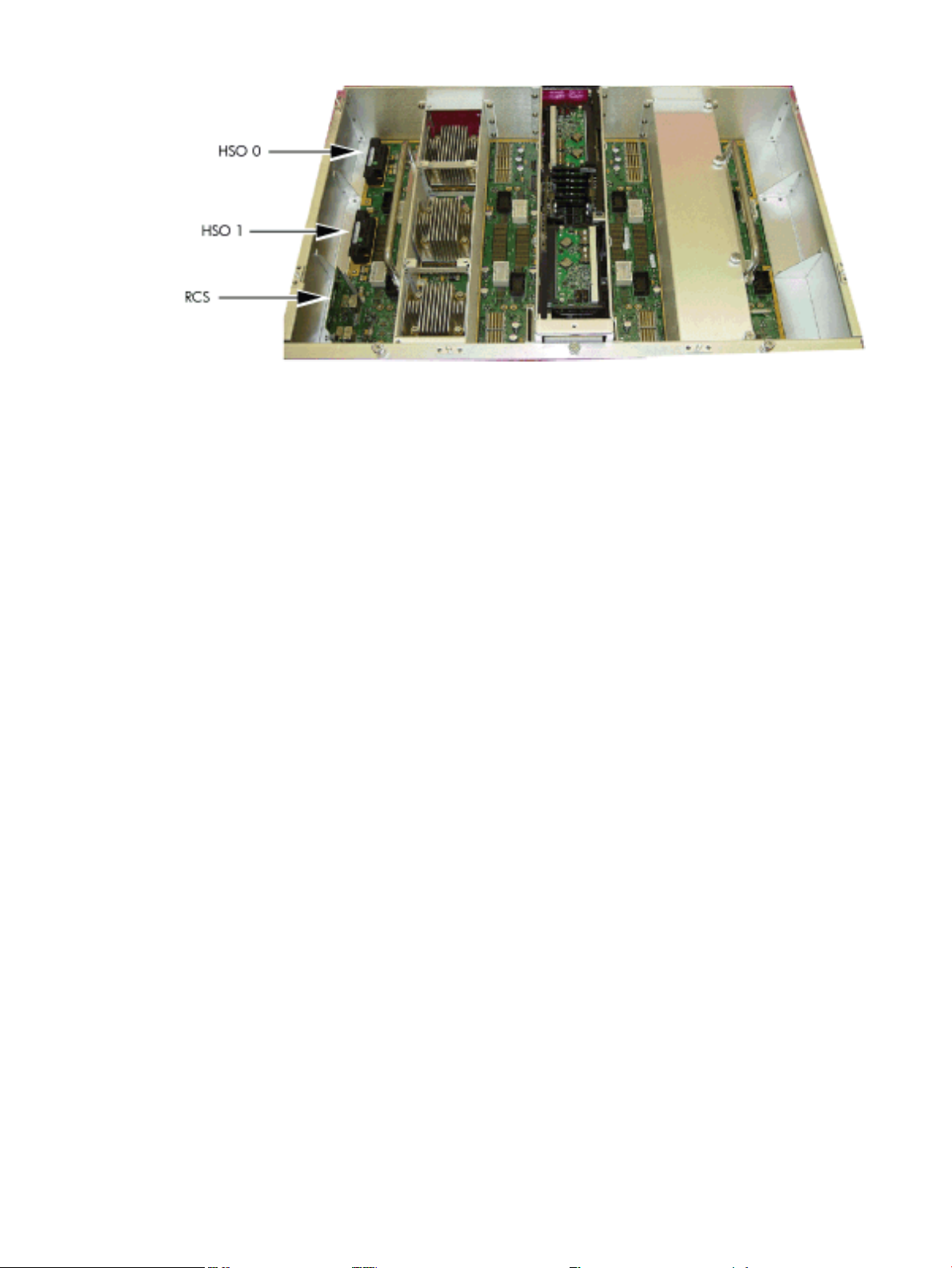
Figure 1-6 HSO and RCS Locations
If only one HSO is plugged in and its output is of valid amplitude, then it is selected. If its output
is valid, then a green LED on the HSO is lit. If its output is not valid, then a yellow LED on the
HSO lights and an alarm signal goes from the RCS to the RPM. The RCS provides a clock that is
approximately 100 KHz less than the correct frequency, even if the output of the HSOs are not
of valid amplitude or no HSOs are plugged in.
If both HSOs are plugged in and their output amplitudes are valid, then one of the two is selected
as the clock source by logic on the RCS. The green LEDs on both HSOs light.
If one of the HSOs outputs does not have the correct amplitude then the RCS uses the other one
as the source of clocks and sends an alarm signal to the RPM indicating which oscillator failed.
The green LED lights on the good HSO and the yellow LED lights on the failed HSO.
If an external clock cable is connected from the master backplane clock output MCX connector
to the slave backplane clock input MCX connector, then this overrides any firmware clock
selections. The clock source from the slave backplane becomes the master backplane.
If firmware selects the margin oscillator as the source of clocks, then it is the source of clocks as
long as there is no connection to the clock input MCX connector from the master backplane.
If the firmware selects the external margin clock SMB connectors as the source of clocks, then it
is the source of clocks as long as no connection exists to the clock input MCX connector from the
master backplane.
Cabinet ID
The backplane receives a 6-bit cabinet ID from the CLU interface J64 connector. The cabinet ID
is buffered and routed to each RPM and to each cell module slot. The RPM decodes the cabinet
number from the cabinet ID and uses this bit to alter the cabinet number bit in the ALBID byte
sent to each XBC through the serial bit stream.
Cell ID
The backplane generates a 3-bit slot ID for each cell slot in the backplane. The slot ID and five
bits from the cabinet ID are passed to each cell module as the cell ID.
Backplane Power Requirements and Power Distribution
The dc power supply for the backplane assembly runs from the cabinet power supply subsystem
through two power cables attached to the backplane. Connectors for the dc supply input have
the same reference designators and are physically located in the same position as on the
Superdome system backplane. The power cables are reused cable assemblies from the Superdome
system and the supply connection is not redundant. One cable is used for housekeeping supply
input. A second cable is used for 48 V supply input.
Backplane 29
Page 30
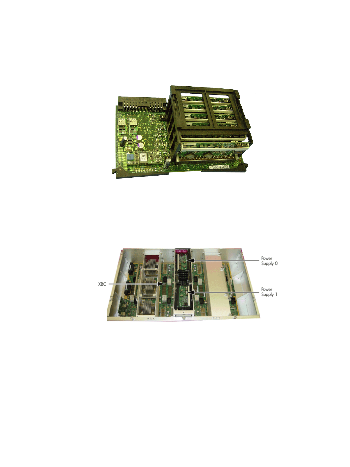
The backplane has two slots for power supply modules. The power supply connector for each
slot has a 1-bit slot address to identify the slot. The address bit for power supply slot 0 is grounded.
The address bit for slot 1 floats on the backplane. The power supply module provides a pull-up
resistor on the address line on slot 1. The power supply module uses the slot address bit as bit
A0 for generating a unique I2C address for the FRU ID prom. Figures 1-7 and 1-8 identify and
show the location of the backplane power supply modules.
Figure 1-7 Backplane Power Supply Module
Each power supply slot has a power supply detect bit that determines if the power supply module
is inserted into the backplane slot. This bit is routed to an input on the RPMs. The RPM provides
a pull-up resistor for logic 1 when the power supply module is missing. When the power supply
module is inserted into the slot, the bit is grounded by the power supply and logic 0 is detected
by the RPM, indicating that the power supply module is present in the backplane slot.
Figure 1-8 Backplane (Rear View)
CPUs and Memories
The cell provides the processing and memory resources required by each sx2000 system
configuration. Each cell includes the following components: four processor module sockets, a
single cell (or coherency) controller ASIC, a high-speed crossbar interface, a high-speed I/O
interface, eight memory controller ASICs, capacity for up to 32 double-data rate (DDR) DIMMs,
high-speed clock distribution circuitry, a management subsystem interface, scan (JTAG) circuitry
for manufacturing test, and a low-voltage DC power interface. Figure 1-9 shows the locations
of the major components.
30 Overview
Page 31

Figure 1-9 Cell Board
Cell Controller
The heart of the cell design is the cell controller. The cell controller provides two front side bus
(FSB) interfaces, with each FSB connected to two processor modules. The communication
bandwidth is 6.8 GB/s sustained at 266.67 MHz on each FSB. This bandwidth is shared by the
two processor modules on the FSB. Interfaces external to the cell provided by the cell controller
consist of three crossbar links, called the fabric interface, and a remote I/O subsystem link. The
fabric interface enables multiple cells to communicate with each other across a self-correcting,
high-speed communication pathway. Sustained crossbar bandwidth is 8.5 GB/s per link at 3.0
GT/s, or 25.5 GB/s across the three links.
The remote I/O link provides a self-correcting, high-speed communication pathway between the
cell and the I/O subsystem through a pair of cables. Sustained I/O bandwidth is 5.5 GB/s for a
50% inbound and outbound mix, and approximately 4.2 GB/s for a range of mixes. The cell
controller interfaces to the cells memory system. The memory interface is capable of providing
a sustained bandwidth of 14 to 16 GB/s at 266.67 MHz to the cell controller.
Processor Interface
The cell controller has two separate FSB interfaces. Each of those FSBs is connected to two
processor sockets in a standard three-drop FSB configuration. The cell controller FSB interface
is pinned out exactly like that of its predecessor cell controller to preserve past cell routing. The
cell controller pinout minimizes total routing delay without sacrificing timing skew between the
FSB address and data and control signals. Such tight routing controls enable the FSB to achieve
a frequency of 266.67 MHz, and the data to be transmitted on both edges of the interface clock.
The 128-bit FSB can achieve 533.33 MT/s, thus 8.5 GB/s burst data transfer rate is possible.
CPUs and Memories 31
Page 32

Processors
There are several Itanium and PA-RISC processor families supported by the processors are
already installed on the cell board. All processors require that a minimum firmware version be
installed. For the processors supported, seeTable 1-2.
Table 1-2 Supported Processors and Minimum Firmware Versions
Core FrequencyMinimum Firmware VersionProcessor Family
Intel ® Itanium® single-core processors with 9 MB cache
Intel ® Itanium® dual-core processors with 18 MB cache
Intel ® Itanium® dual-core processors with 24 MB cache
Intel ® Itanium ® dual-core 9100 series processors with 18
MB cache
Intel ® Itanium ® dual-core 9100 series processors with 24
MB cache
Rules for Processor Mixing
• Processor families cannot be mixed on a cell board or within a partition
• Processor frequencies cannot be mixed on a cell board or within a partition
• Cache sizes cannot be mixed on a cell board or within a partition
• Major processor steppings cannot be mixed on a cell board or within a partition
• Full support for Itanium and PA-RISC processors within the same complex but in different
partitions
Cell Memory System
1.6 GHz4.3e (IPF SFW 004.080.000)
1.6 GHz5.5d (IPF SFW 005.024.000)
1.6 GHz5.5d (IPF SFW 005.024.000)
1.1 GHzPDC_FW 042.009.000PA-8900 dual-core processor with 64 MB cache
1.6 GHz8.6d (IPF SFW 009.022.000)
1.6 GHz8.6d (IPF SFW 009.022.000)
Each cell in the sx2000 system has its own independent memory subsystem. This memory
subsystem consists of four logical memory subsystems that achieve a combined bandwidth of
17 GB/s peak, 14-16 GB/s sustained. This cell is the first of the Superdome designs to support the
use of DDR I/O DRAM. These DIMMs are to be based on the DDR-II protocol, and the cell design
supports DIMM capacities of 1, 2, or 4 GB using monolithic DRAMs. Nonmonolithic, (stacked)
DRAMS are not supported on the sx2000. The additional capacitive load and requirement for
additional chip selects is not accommodated by the new chipset. All DIMMs used in the sx2000
are compatible with those used in other new CEC platforms. However other platforms can
support DIMMs based on nonmonolithic DRAMs that are incompatible with the sx2000. Cell
memory is illustrated in Figure 1-10.
32 Overview
Page 33

Figure 1-10 Cell Memory
DIMMs are named according to both physical location and loading order. The physical location
is used for connectivity on the board and is the same for all quads. Physical location is a letter
(A or B) followed by a number (0, 1, 2, or 3). The letter indicates whichside of the quad the DIMM
is on. A is the left side, or the side nearest CC. The DIMMs are then numbered 0 through 3,
starting at the outer DIMM and moving inwards the memory controllers.
Memory Controller
The memory controller CEC's primary function is to source address and control signals and
multiplex and demultiplex data between the CC and the devices on the DDR DIMMs. Four
independent memory blocks, consisting of two memory controllers and eight DIMMs, are
supported by interface buses running between the CC and the memory controller. The memory
controller converts these link streams to the correct signaling voltage levels (1.8 V) and timing
for DDR2 protocol.
Bandwidth is limited by the memory interface buses that transfer data between the CC and the
memory controller. The memory controller also performs the write (tag update) portion of a
read-modify-write (RMW) access. The memory controller is bit sliced, and two controllers are
required to form one 72-bit CC memory interface data (MID) bus. The CC MID buses are
bidirectional, source synchronous, and run at 533.33 MT/s. The memory side of a pair of memory
controller ASICs consists of two 144-bit bidirectional DDR2 SDRAM data buses operating at
533.33 MT/s. Each bus supports up to four echelons of DRAMs.
DIMM Architecture
The fundamental building block of the DIMM is a DDR2 DRAM with a 4-bit data width. Each
DIMM transfers 72 bits of data on a read/write, and the data is double-clocked at a clock frequency
of 266.67 MHz for an effective peak transfer rate of 533.33 MT/s. Each DIMM includes 36 DRAM
devices for data storage and two identical custom address buffers. These buffers fan out and
check the parity of address and control signals received from the memory controller. The DIMM
densities for the sx2000 are 1 GB (256 Gb DRAMs), 2 GB (512 Gb DRAMs), and 4 GB (1 Gb
DRAMs). The new sx2000 chipset DIMMs have the same mechanical form factor as the DIMMs
used in Integrity systems, but the DIMM and the connector, are keyed differently from previous
DIMM designs to prevent improper installation. The DIMM is roughly twice the height of an
industry-standard DIMM. This height increase enables the DIMM to accommodate twice as
many DRAMs as an industry-standard DIMM and provides redundant address and control
signal contacts not available on industry-standard DDR2 DIMMs.
Memory Interconnect
MID bus data is transmitted through the four 72-bit,ECC-protected MID buses, each with a clock
frequency equal to the CC core frequency. The data is transmitted on both edges of the clock, so
the data transfer rate (533 MT/s) of each MID is twice the MID clock frequency (267 MHz). A
CPUs and Memories 33
Page 34

configuration of at least eight DIMMs (two in each quadrant) activates all four MID buses. The
theoretical bandwidth of the memory subsystem can be calculated as follows: (533 MT/s * 8
Bytes/T * 4) = 17 GB/s The MID buses are bit-sliced across two memory controllers with 36-bits
of data going to each memory controller. In turn, each memory controller takes that high-speed
data (533 MT/s) from the MID, and combines four consecutive MID transfers to form one 144-bit
DRAM bus. This DRAM bus is routed out in two 72-bit buses to two DIMM sets, which include
four DIMMs each. The DDR DRAM bus runs at 267 MT/s and data is clocked on both edges of
the clock.
The DDR DRAM address and control (MIA) signals for each quadrant originate at the CC and
are routed to the DIMMs through the memory controller. On previous systems, these signals
did not touch the memory chips; they were routed to the DIMMs through fan out buffers. The
DRAM address and control signals are protected by parity so that signaling errors are detected
and do not cause silent data corruption. The MIA bus, comprised of the SDRAM address and
control signals, is checked for parity by the memory controller. Each of the 32 DIMMs can
generating a unique parity error signal that is routed to one of four parity error inputs per memory
controller. Each memory controller then logically gates the DIMM parity error signals it receives
with its own internal parity checks for the MIC and MIT buses. This logical gating results in a
single parity error output that is driven to the CC and latched as an event in an internal
memory-mapped register.
Eight unique buses for command and control signals are transmitted from the CC to each memory
controller simultaneously with the appropriate MID bus interconnect. Each MIC bus includes
four signals running at 533 MT/s. Each command on the MIC bus takes four cycles to transmit
and is protected by parity so that signaling errors are detected and do not cause silent data
corruption.
Four MIT buses are routed between the CC and the designated tag memory controllers. MIT
buses run at 533 MT/s and use the same link type as the MID buses. Each MIT bus includes six
signals and a differential strobe pair for deskewing. As with the MIA and MIC buses, the MIT
is protected by parity so that signaling errors are detected and do not cause silent data corruption.
Mixing Different Sized DIMMs
Mixing different sized DIMMs is allowed, provided you follow these rules:
• An echelon of DIMMs consists of two DIMMs of the same type.
• All supported DIMM sizes can be present on a single cell board at the same time, provided
previous rule is satisfied.
• Memory must be added in one echelon increments.
• The amount of memory contained in an interleaved group must be 2n bytes.
Memory Interleaving
Memory is interleaved in the following ways on sx2000 systems:
• MBAT (across DIMMs)
• Cell map (across cells)
• Link (across fabrics)
Memory Bank Attribute Table
The memory bank attribute table (MBAT) interleaving is done on a per-cell basis before the
partition is rendezvoused. The cell map and fabric interleaving are done after the partition has
rendezvoused. SDRAM on the cell board is installed in physical units (echelons). The sx2000 has
16 independent echelons. Each echelon consists of two DDRDIMMs. Each rank can have multiple
internal logical units called banks, and each bank contains multiple rows and columns of memory.
An interleaving algorithm determines how a rank, bank, row, or column address is formed for
a particular physical address.
34 Overview
Page 35

The 16 echelons in the memory subsystem can be subdivided into four independent memory
quadrants accessed by four independent MID buses. Each quadrant contains two independent
SDRAM buses. Four echelons can be installed on each SDRAM bus. The CC contains four MBATs,
one for each memory quadrant. Each MBAT contains eight sets of routing CSRs (one per rank).
Each routing CSR specifies the bits of the address that are masked or compared to select the
corresponding rank, referred to as interleave bits. The routing CSR also specifies how the
remaining address bits are routed to bank, row, and column address bits.
To optimize bandwidth, consecutive memory accesses target echelons that are as far from each
other as possible. For this reason, the interleaving algorithm programs the MBATs so that
consecutive addresses target echelons in an order that skips first across quadrants, then across
SDRAM buses, then across echelons per SDRAM bus, then across banks per rank.
Cell Map
Cell mapping creates a scheme that is easy to implement in hardware. It enables easy calculation
of the interleaving parameters for software. In order to do this part of the physical address to
perform a lookup into a table, it gives the actual physical cell and ways of interleaving into
memory at this address. Be aware of the following:
• A portion of memory that is being interleaved across must start at an offset that is a multiple
of the memory chunk for that entry. For example, to interleave across 16 GB of memory with
one entry, the starting address for this chunk must be 0 GB, 16 GB, 32 GB, 48 GB, or 64 GB.
If using three 2 GB entries to interleave across three cells, then the multiple must be 2 GB,
not 6 GB.
• Interleaving is performed across the actual cells within the system. Interleaving can be done
across a minimum of 0.5 GB on a cell, and a maximum interleave across 256 GB per cell.
• Each cell in an interleave group must have the same amount of memory interleaved. That
is, you cannot interleave 2 GB in one cell and 4 GB in another cell.
The cell map remains the same size as in previous HP Integrity CECs.
Link Interleaving
The link interleaving functionality did not exist in sx1000. This logic is new for the sx2000 CC.
The sx2000 enables cells to be connected through multiple paths. In particular, each CC chip has
three crossbar links. When one CC sends a packet to another CC, it must specify which link to
use.
The CC is the sx2000 chipset cell controller. It interfaces to processors,main memory, the crossbar
fabric, an I/O subsystem, and processor-dependent hardware (PDH). Two data path CPU bus
interfaces are implemented, with support for up to four processors oneach bus. The CC supports
bus speeds of 200 MHz and 267 MHz. The 128-bit data bus is source synchronous, and data can
be transferred at twice the bus frequency: 400 MT/s or 533 MT/s. The address bus is 50 bits wide,
but only 44 bits are used by the CC. Error correction is provided on the data bus and parity
protection is provided on the address bus.
Memory Error Protection
All of the CC cache lines are protected in memory by an error correction code (ECC). The sx2000
memory ECC scheme is significantly different from the sx1000 memory ECC scheme. An ECC
code word is 288 bits long: 264 bits of payload (data and tag) and 24 bits of redundancy. An ECC
code word is contained in each pair of 144-bit chunks. The first chunk in the pair (for example
chunk 0 in the 0,1 pair) contains all the even nibbles of the payload and redundancy, and the
second chunk contains all the odd nibbles. The memory data path (MDP) block checks for, and
if necessary, corrects any correctable errors.
CPUs and Memories 35
Page 36

DRAM Erasure
A common cause of a correctable memory error is a DRAM failure; the ability to correct this type
of memory failure in hardware is called chip kill. Address or control bit failure is a common
cause. Chip kill ECC schemes have added hardware logic that enables them to detect and correct
more than a single-bit error when the hardware is programmed to do so. A common
implementation of traditional chip kill is to scatter data bits from each DRAM component across
multiple ECC code words, so that only one bit from each DRAM is used per ECC code word.
Double chip kill is an extension to memory chip kill that enables the system to correct multiple
ECC errors in an ECC code word. Double chip kill is also known as DRAM erasure.
DRAM erasure is invoked when the number of correctable memory errors exceeds a threshold.
It can be invoked on a memory subsystem, bus, rank or bank. PDC tracks the errors on the
memory subsystem, bus, rank and bank in addition to the error information it tracks in the PDT.
PDC Functional Changes
There are three primary threads of control in the processordependent code (PDC): the bootstrap,
the errors code, and the PDC procedures. The bootstrap is the primary thread of control until
the OS is launched. The boot console handler (BCH) acts as a user interface for the bootstrap,
but can also be used to diagnose problems with the system. The BCH can call the PDC procedures
but this explicit capability is only available in MFG mode through the Debug menu.
The PDC procedures are the primary thread of control once the OS launches. Once the OS
launches, the PDC code is only active when the OS calls a PDC procedure or there is an error
that calls the error code. Normally, the error thread of control returns control back to the OS
through OS_HPMC, OS_TOC or RFI (LPMC or CMCI). In some cases, the HPMC or MCA handler
halts the cell or partition.
If a correctable memory error occurs during run time, the new chipset logs the error and corrects
it in memory (reactive scrubbing). Diagnostics periodically call PDC_PAT_MEM (Read Memory
Module State Info) to read the errors logs. When this PDC call is made, system firmware updates
the PDT, and deletes entries older than 24 hours in the structure that counts how many errors
have occurred for each memory subsystem, bus, rank or bank. When the counts exceed the
thresholds, PDC invokes DRAM erasure on the appropriate memory subsystem, bus, rank or
bank. Invoking DRAM erasure does not interrupt the operation of the OS.
When PDC invokes DRAM erasure, the information returned by PDC_PAT_MEM (Read Memory
Module State Info) indicates the scope of the invocation and provides information to enable
diagnostics to determine why it was invoked. PDC also sends IPMI events indicating that DRAM
erasure is in use. When PDC invokes DRAM erasure, the correctable errors that caused DRAM
erasure are removed from the PDT. Because invoking DRAM erasure increases the latency of
memory accesses and reduces the ability of ECC to detect multibit errors, you must notify the
customer that the memory subsystem must be serviced. HP recommends that the memory
subsystem be serviced within a month of invoking DRAM erasure on a customer machine.
The thresholds for invoking DRAM erasure are incremental, so that PDC invokes DRAM erasure
on the smallest part of memory subsystem necessary to protect the system against another bit
error.
Platform Dependent Hardware
The platform dependent hardware (PDH) includes functionality that is required by both system
and management firmware. The PDH provides the following features:
• An interface that passes multiple forms of information between system firmware and the
MP onthe SBCby the platform dependent hardware controller (PDHC, on the PDH daughter
card).
• Flash EPROM for PDHC boot code storage.
• PDHC SRAM for operational instruction and data storage.
36 Overview
Page 37

Reset
• Memory mapped control and status registers (CSRs) control the cell for management needs.
• System management bus (SMBus) reads the processor module information EEPROM, scratch
EEPROM, and thermal sensing device.
• I2C bus reads PDH, cell, and cell power board FRU ID information.
• Serial presence detect (SPD) bus detects and investigates loaded DIMMs.
• Timing control of cell reset signals.
• Logic analyzer ports for access to important PDH signals.
• PDH resources accessible by the processors (system firmware) and the management
subsystem.
• Flash EPROM for system firmware bootstrap code storage and update capability.
• System firmware scratch pad SRAM for operation instruction and data storage.
• Battery backed NVRAM and real time clock (RTC) chip to provide wall clock time.
• Memory-mapped registers for configuration related information
• Console UARTs (moved from I/O space).
• Low level debug and general purpose debug ports (UART).
• Trusted platform monitor (TPM).
The sequencing and timing of reset signals is controlled by the LPM, a field-programmable gate
array (FPGA) that resides on the cell. The LPM is powered by the housekeeping rail and has a
clock input from the PDH daughter card that runs continuously at 8 MHz. This enables the LPM
and the rest of the utility subsystem interface to operate regardless of the power state of the cell.
Cell reset can be initiated from the following sources:
• Power enable of the cell (initial power-on)
• Backplane reset causes installed cells to reset, or cell reset initiated from PDHC in direct
response to an MP command or during a system firmware update
• System firmware-controlled soft reset initiated by writing into the PDH interface chip test
and reset register
The LPM contains a large timer that gates all the reset signals and ensures the proper signaling
sequence regardless of the source of that reset event. The most obvious reset sequencing event
is the enabling of power to the cell, but the sequencing of the reset signals is consistent even if
the source of that reset is an MP command reset for the main backplane, a partition, or the cell
itself.
Cell OL*
For online add (OLA) of a cell, the CC goes through the normal power on reset sequence. For
online delete (OLD) of a cell, software cleans up to the I/O (SBA) interface to put it in reset mode
and hold it there. When the I/O (SBA) link is held in reset, the cell is ready; power can be turned
off and the cell can be removed.
I/O Subsystem
The SIOBP is an update of the GXIOB, with a new set of chips that increase the board’s internal
bandwidth and support the newer PCI-X 2.0 protocol. The SIOBP uses most of the same
mechanical parts as the GXIOB. The connections between the I/O chassis and the rest of the
system have changed. The cell board to I/O backplane links are now multichannel, high-speed
serial (HSS) based rather than a parallel interface. Because of this, the SIOBP can only be paired
with the sx2000 cell board and is not backward compatible with earlier Superdome cell boards.
The term PCI-X I/O chassis refers to the assembly containing an SIOBP. All slots are capable of
supporting both PCI and PCI-X cards.
I/O Subsystem 37
Page 38

A new concept for the sx2000 is a fat rope. A fat rope is logically one rope that has 32 wires. It
consists of two single ropes but has the four command wires in the second single rope removed.
The concept of a single rope remains unchanged. It has 18 signals, of which 10 are bidirectional,
single-ended address and data bits. Two pairs of unidirectional, single-ended lines carry
commands in each direction and a differential strobe pair for each direction. These are all enhanced
ropes, which support double the bandwidth of plain ropes and additional protocol behavior.
Ropes transfer source-synchronous data on both edges of the clock and can run at either of two
speeds.
The major components in the I/O chassis are the system bus adapter (SBA) ASIC and 12 logical
bus adapter (LBA) ASICs. The high speed serial (HSS) links (one inbound and one outbound)
are a group of 20 high-speed serial differential connections using a cable that enables the I/O
chassis to be located as much as 14 feet away from the cell board. This enables the use of an I/O
expansion cabinet to provide more I/O slots than fit in the main system cabinet.
Enhanced ropes are fast, narrow links that connect singly or in pairs between the SBA and four
specific LBAs. Fat ropes are enhanced dual-width ropes that are treated logically asa single rope.
A fat rope can connect to an LBA. Dual fat ropes can connect to an LBA.
A PCI-X I/O chassis consist of four printed circuit assemblies(the PCI-X I/O backplane, the PCI-X
I/O power board, the PCI-X I/O power transfer board, and the doorbell board) plus the necessary
mechanical components required to support 12 PCI card slots.
The master I/O backplane (HMIOB) provides easy connectivity for the I/O chassis. The HSS link
and utilities signals come through the master I/O backplane. Most of the utilities signals travel
between the UGUY and the I/O backplane, with a few passing through to the I/O power board.
The I/O power board contains all the power converters that produce the various voltages needed
on the I/O backplane. Both the I/O backplane and the I/O power board have FRU EEPROMs. An
I/O power transfer board provides the electrical connections for power and utility signals between
the I/O backplane and I/O power board.
PCI-X Backplane Functionality
The majority of the functionality of a PCI-X I/O backplane is provided by a single SBA ASIC and
twelve LBA ASICs (one per PCI slot). A dual-slot hot-plug controller chip plus related logic is
also associated with each pair of PCI slots. The SBA is the primary I/O component. Upstream,
the SBA communicates directly with the cell controller CC ASIC of the host cell board through
a high-bandwidth logical connection (HSS link). Downstream, the SBA spawns 16 logical ropes
that communicate with the LBA PCI interface chips. Each PCI chip produces a single 64-bit PCI-X
bus supporting a single PCI or PCI-X add-in card. The SBA and the CC are components of the
sx2000 and are not compatible with the legacy or Integrity CECs.
The newer design for the LBA PCI chip replaces the previous design for LBA chip providing
PCI-X 2.0 features. Link signals are routed directly from one of the system connector groups to
the SBA. The 16 ropes generated by the SBA are routed to the LBA chips as follows:
• The four LBAs are tied to the SBA by single-rope connections and are capable of peak data
rates of 533 MB/s (equivalent to the peak bandwidth of PCI 4x or PCIX-66).
• LBAs are tied to the SBA by either a single fat or dual-rope connections and are capable of
peak data rates of 1.06 GB/s (equivalent to the peak bandwidth of PCIX-133). Two LBAs use
dual-fat rope connections and are capable of peak data rates of 2.12 GB/s (equivalent to the
peak bandwidth of PCIX-266).
Internally, the SBA is divided into two halves, each supporting four single ropes and four fat
ropes. The I/O backplane routing interconnects the ASICs in order to balance the I/O load on
each half of the SBA.
SBA Chip CC-to-Ropes
The SBA chip communicates with the CC on the cell board through a pair of high-speed serial
unidirectional links (HSS or e-Links). Each unidirectional e-Link consists of 20 serial 8b/10b
38 Overview
Page 39

encoded differential data bits operating at 2.36 GT/s. This yields a peak total bidirectional HSS
link bandwidth of 8.5 GB/s. Internally, SBA routes this high-speed data to and from one of two
rope units. Each rope unit spawns four single ropes and four fat ropes. A maximum of two like
ropes can connect to an LBA. This means that the SBA to LBA rope configurations can be single,
dual, or fat ropes and the SBA-to-LBA rope configurations can be single, dual, fat or dual fat
ropes.
In a default configuration, ropes operate with a 133 MHz clock and so have 266 MT/s for a peak
bandwidth (266 MB/s per single rope). In the enhanced configuration, ropes operate with a 266
MHz clock and so have 533 MT/s for a peak bandwidth 533 MB/s per single rope. On the SIOBP,
firmware is expected to always configure the 266 MHz enhanced ropes.
Ropes can be connected to an LBA either individually or in pairs. A single rope can sustain up
to PCI 4x data rates (full bandwidth support for a 64-bit PCI card at 33 or 66 MHz or for a 64-bit
PCI-X card at 66 MHz for a 32-bit PCI-X card at 133 MHz). A dual rope or fat rope can sustain
PCI 8x data rates (64-bit PCI-X card at 133 MHz). A dual fat rope can sustain PCI 16x data rates
(64-bit PCI-X card at 266 MHz). Because of the internal architecture of the SBA, when two ropes
are combined, they must be adjacent even/odd pairs. Ropes 0 and 1 can be combined, but not 1
and 2. The two paired ropes must also be of the same type, either single or fat.
The location of the ropes on the SBA chip determines the rope mapping to PCI slots on the I/O
backplane (Figure 1-11 “PCI-X I/O Rope Mapping”).
Figure 1-11 PCI-X I/O Rope Mapping
Ropes-to-PCI LBA Chip
The LBA ASIC interfaces between the ropes and the PCI bus. The primary enhancement to the
LBA ASIC is support of PCI-X 2.0 266 MHz bus operation. The extra bandwidth requirements
of the higher speed PCI-X bus are met by widening the ropes interface to accept single, dual, fat,
or dual fat ropes. Another LBA enhancement is selectable ECC protection on the data bus.
The SIOBP board has six LBAs configured with either dual ropes or a fat rope. This provides
enough bandwidth for PCI-X 133 MHz 64-bit or less operation. Two LBA chips are configured
with dual fat ropes (slots 5 and 6) that provide enough bandwidth to support PCI-X 2.0 running
at 266 MHz 64-bit or less. Each LBA is capable of only 3.3 V or 1.5 V signaling on the PCI bus.
I/O Subsystem 39
Page 40

PCI Slots
Cards that allow only 5 V signaling are not supported; PCI connector keying prevents insertion
of such cards.
Each LBA has control and monitor signals for use with a PCI hot-swap chip. It also converts PCI
interrupts into interrupt transactions which are fed back to the CPUs.
For maximum performance and availability, each PCI slot is sourced by its own LBA chip and
is supported by its own portion of a hot-plug controller. All slots are designed to Revision 2.2 of
the PCI specification and Revision 2.0a of the PCI-X specification and can support full size 64–bit
cards with the exceptions noted below. Shorter or smaller cards are also supported, as are 32-bit
cards. Slot 0 support for the core I/O card is removed on the SIOBP.
SIOBP PCI slot support of VAUX3.3 and PME is not be supported. SMBus is supported in
hardware through two I2C Muxes. Firmware can configure the muxes to enable communication
to any of the 12 PCI slots. JTAG is not supported for PCI slots.
Each device on a PCI bus is assigned a physical device number. On the past HIOB, the slot was
configured as device 0. However, the PCI-X specification requires that the host bridge to be
device 0. So for SIOBP the slot is configured as device 1.
The SIOBP's ten outermost slots support only 3.3 V signaling (PCI or PCI-X Mode 1). The two
innermost slots support either 3.3 V or 1.5 V (PCI-X Mode 2) signaling. All SIOBP PCI connectors
physically prevent 5 V signaling cards from being installed.
Mixed PCI-X and PCI Express I/O Chassis
The 12-slot mixed PCI-X/PCI Express (PCIe) I/O chassis was introduced for the sx2000 Superdome
with the two new dual-core Intel ® Itanium® processors and is heavily leveraged from the 12-slot
PCI-X I/O chassis. The primary change replaces six of the LBAs with a new LBA ASIC to provide
six PCI Express 1.1 compliant slots. The PCI-X/PCIe I/O chassis is only supported for Intel ®
Itanium® dual-core processors.
The new LBA provides an 8-lane (x8) Root Port compliant with the PCIe 1.1 specification. The
six corresponding slots are compatible with PCIe cards with x8 or smaller edge connectors. PCIe
slots are not compatible with PCI or PCI-X cards. Physical keying prevents installation of PCI
or PCI-X cards into PCIe slots, or PCIe cards into PCI-X slots.
The new PCIe I/O backplane board is a respin of the SIOBP3, with six of the LBA ASICs replaced
with new PCIe LBA ASICs. These new LBA ASICs populate slots 2, 3, 4, 5, 6, and 7. All other
slots contain PCI LBA ASICs. Slot 2 is a dual-thin rope; slots 3, 4, and 7 are fat-ropes and slots 5
and 6 are dual-fat ropes. All slots are hot-pluggable (Figure 1-12 “PCIe I/O Rope Mapping”).
The new AIOBP I/O backplane uses most of the same mechanical components as the SIOBP. The
differences are the PCIe connector, and the card extractor hardware.
A PCI-X I/O chassis consists of four printed circuit assemblies; the PCI-X I/O backplane, the
PCI-X I/O power board, the PCI-X I/O power transfer board, and the doorbell board plus the
necessary mechanical components required to support 12 PCI card slots.
40 Overview
Page 41

Figure 1-12 PCIe I/O Rope Mapping
PCI Hot-Swap Support
All 12 slots support PCI hot-plug permitting OLA and OLD of individual I/O cards without
impacting the operation of other cards or requiring system downtime. Card slots are physically
isolated from each other by nonconductive card separators that also serve as card ejectors to aid
in I/O card removal. A pair of light pipes attached to each separator conveys the status of the
slot power (green) and attention (yellow/amber) LEDs, clearly associating the indicators with
appropriate slots. An attention button (doorbell) and a manual retention latch (MRL) is associated
with each slot to support the initiation of hot-plug operations from the I/O chassis.
The core I/O provided a base set of I/O functions required by Superdome protection domains.
In past Superdomes, PCI slot 0 of the I/O backplane provided a secondary edge connector to
support a core I/O card. In the sx2000 chipset, the core I/O function is moved onto the PDH card,
and the extra core I/O sideband connector is removed from the SIOBP board.
System Management Station
The Support Management Station (SMS) provides support, management and diagnostic tools
for field support. This station combines software applications from several organizations within
HP onto a single platform with the intent of helping field support reduce MTTR. Applications
running on the SMS include tools to collect and analyze system log information, analyze and
decode crash dump data, perform scan diagnostics, and provide configuration rules and
recommendations for the CE's. The SMS also acts as an FTP server for the PDC, Itanium, and
manageability firmware files needed to perform firmware updates on the systems. The SMS is
also host to the Partition Manager Command-Line Interface tool used for partitioning the sx1000
and sx2000 platforms. The SMS software runs on both a Windows-based PC and an HP-UX
workstation (Table 1-3 “SMS Lifecycles”). The SMS supports both HP Superdome Integrity and
PA-RISC systems. By default, customer orders specify the PC SMS for new systems. Support for
sx1000 and sx2000 systems is provided for the HP-UX workstations currently in the field. New
customers will purchase a Windows-based HP Series rp5700 PC. The support provided on the
prior generation of SMS is equivalent to that available for Superdome but does not include new
capabilities developed for theWindows environment. Each customer site containing a Superdome
system must have at least one SMS . The SMSs must have an Ethernet connection to the
System Management Station 41
Page 42

management LAN of each system MP on which it is used. If possible, locate the SMS close to the
system being tested so field support has convenient access to both machines.
Table 1-3 SMS Lifecycles
ConsoleSMSSuperdome
Supported PC/workstation (e.g.B2600)rp2470Legacy prior to April 2004
Legacy after April 2004
upgraded to sx1000 and sx2000
New sx1000 and sx2000
User Accounts
Two standard user accounts are created on the SMS. The first account user name is root and it
uses the standard root password for Superdome SMS stations. This account has administrative
access. The second account user name is hduser and it uses the standard hduser password for
the Superdome SMS stations. This account has general user permissions.
Legacy
September 2009
TFT5600UNIX SMS: rx2600
HP-UX 11i v2 ONLY
Windows SMS: ProLiant ML350 G4P, TFT5600 & Ethernet switch
Windows 2000 Server SP4
Existing console deviceAny HP-UX 11.0 or later SMS with
software upgrade
Windows SMS: ProLiant ML350 G5, TFT7600 & Ethernet switch
Windows Server 2000
TFT7600UNIX SMS: rx2620
HP-UX 11i v2 ONLY
TFT7600Windows HP PC SMSsx1000 and sx2000 beginning
New Server Cabling
Three new Superdome cables designed for the sx2000 improve data rate and electrical
performance:
• an m-Link cable
• two types (lengths) of e-Link cable
• a clock cable
m-Link Cable
The m-Link cable (A9834-2002A) is the primary backplane to second cabinet backplane high
speed interconnect. The m-Link cable connects XBCs between system and I/O backplanes. The
cable uses 4x10 HMZD connectors with Amphenol Spectra-Strip 26AWG twin-ax cable material.
The m-Link cable is designed with one length but it is used in several connecting points. Thus,
you must manage excessive cable length carefully. The ideal routing keeps m-Link cables from
blocking access of power and XBC modules. Twelve high-speed cables must be routed around
the backplane frame with the support of mechanical retentions. The m-Link cable is designed
with a more robust dielectric material than the legacy REO cable and can withstand a tighter
bend radius. However, HP recommends keeping the minimum bend radius at 2 inches.
e-Link Cable
The e-Link cables (A9834-2000B) are seven feet long cables and the external e-Link cable
(A9834-2001A) is 14 feet long. Both use 2-mm HM connectors with Gore 26AWG PTFE twin-ax
cable material. The e-Link cable connects the cell to the local I/O chassis, and the external e-Link
42 Overview
Page 43

cable connects the cells to a remote PCI-X chassis. Because both the e-Link and the external e-Link
use the same cable material as the legacy REO cable, cable routing and management of these
cables in sx2000 system remain unchanged relative to Superdome. The external e-Link cable
requires a bend radius no smaller than two inches. The e-Link cable requires a bend radius no
smaller than four inches. Figure 1-13 illustrates an e-Link cable.
Figure 1-13 e-Link Cable
During system installation, two internal e-Link or two external e-Link cables are needed for each
cell board and I/O backplane. Twelve m-Link cables are needed for each dual-cabinet
configuration.
New Server Cabling 43
Page 44

Figure 1-14 Backplane Cables
Clock Cable
The clock distribution to a second cabinet for the sx2000 requires a new cable (A9834-2003A).
Firmware
The newer Intel® Itanium® Processor firmware consists of many components loosely coupled
by a single framework. These components are individually linked binary images that are bound
together at run time. Internally, the firmware employs a software database called a device tree
to represent the structure of the hardware platform and to provide a means of associating software
elements with hardware functionality.
Itanium or PA-RISC firmware releases for HP Integrity Superdome/sx2000 or HP 9000/sx2000
are available.
Itanium Firmware for HP Integrity Superdome/sx2000
The Itanium firmware incorporates the following firmware interfaces:
44 Overview
Page 45

Figure 1-15 Itanium Firmware Interfaces
• Processor Abstraction Layer (PAL) provides a seamless firmware abstraction between the
processor, the system software, and the platform firmware.
• System Abstraction Layer (SAL) provides a uniform firmware interface and initializes and
configures the platform.
• Extensible Firmware Interface (EFI) provides an interface between the OS and the platform
firmware.
• Advanced Configuration and Power Interface (ACPI) provides a new standard environment
for configuring and managing server systems. It moves system configuration and
management from the BIOS to the operating system and abstracts the interface between the
platform hardware and the OS software, thereby enabling each to evolve independently of
the other.
The firmware supports HP-UX 11i version 2, Linux, Windows, and OpenVMS through the
Itanium® processor family standards and extensions. It includes no operating system-specific
functionality. Every OS is presented the same interface to system firmware, and all features are
available to each OS.
NOTE: Windows Server 2003 Datacenter does not support the latest ACPI specification (2.0).
The firmware must provide legacy (1.0b) ACPI tables.
Using theacpiconfig command, the ACPI tables presented to the OS are different. The firmware
implements the standard Intel® Itanium® Processor family interfaces with some
implementation-specific enhancements that the OS can use but is not required to use, such as
page deallocation table reporting, through enhanced SAL_GET_STATE_INFO behavior.
User Interface
The Intel® Itanium® processor family firmware employs a user interface called the Pre-OS
system startupenvironment (POSSE).The POSSEshell isbased on the EFI shell. Several commands
were added to the EFI shell to support HP value-added functionality. The new commands
encompass functionality similar to BCH commands on PA-RISC systems. However, the POSSE
shell is not designed to encompass all BCH functionality. They are separate interfaces.
Error and Event IDs
The new system firmware generates event IDs, similar to chassis codes, for errors, events, and
forward progress to the MP through common shared memory. The MP interprets, stores, and
reflects these event IDs back to running partitions. This helps in the troubleshooting process.
Firmware 45
Page 46

The following seven firmware packages installed in the sx2000 to support the IPMI manageability
environment:
• Management Processor (h_mp.xxx.xxx.xxx.frm)
• Power Monitor (h_pm.xxx.xxx.xxx.frm)
• Cabinet-Level Utilities (h_clu.xxx.xxx.xxx.frm)
• Cell (h_cell_pdh.xxx.xxx.xxx.frm)
• Processor-Dependent Hardware Code (h_pdhc.xxx.xxx.xxx.frm)
• Event Dictionary (h_ed.xxx.xxx.xxx.frm)
• Intel® Itanium® Processor Family Firmware (ipf.x.xx.frm)
For the latest Superdome sx2000 firmware levels, check your Engineering Advisories.
To update firmware on the Superdome sx2000, use the fw command from the MP Main Menu.
MP MAIN MENU:
CO: Consoles
VFP: Virtual Front Panel
CM: Command Menu
CL: Console Logs
SL: Show Event Logs
FW: Firmware Update
HE: Help
X: Exit Connection
Itanium System Firmware Functions
Support for HP-UX, Windows (Enterprise Server and Data Center), Linux, and OpenVMS
• Support for EFI 1.10.14.61 and EFI 1.1 I/O drivers
• Support for ACPI 1.0b up through 2.0c (OS-dependent)
• Parallel main memory initialization. Support for double chip-spare in memory ECC code
• OLAD of new cells with noninterleaved memory, OLAD I/O cards
• Support for link level retry with self-healing for crossbar and I/O links
• Support for both native and EBC EFI I/O card drivers
• Maximum 128 CPU cores per partition (8 CPU cores per cell)
• Supports mixing Itanium cells of different frequencies or major steps (generations) in separate
partitions within a complex
• Supports mixing of Itanium and PA-RISC processors in the same complex but in different
partitions.
• Support for 1, 2, and 4 GB DDR-II DIMMs
• Support for mixed DIMMs on a cell
• Support for common DIMMs across sx2000 platforms
• Supports nonuniform memory configurations within a partition
• Address parity checking on DIMMs (no address ECC)
• Support for cell local memory
• Support for adding DIMMs in increments of eight
• Support for new LBA and PCI-X 2.0 (266 MHz) (PCI compatible)
• Support for all PCI-X and PCI cards supported by respective sx1000 systems
• Elimination of Superdome core I/O card for Superdome/sx2000 console
• Infiniband supported using PCI-X cards only
• Support for shadowed system firmware flash
PA-RISC Firmware for HP 9000/sx2000 Servers
The PA-RISC firmware incorporates firmware interfaces shown in Figure 1–18.
46 Overview
Page 47

Figure 1-16 PA-RISC Firmware Interfaces
PA-RISC System Firmware Functions
• Supports only HP-UX
• Supports mixing of PA-RISC and Itanium cell boards in the same complex but in different
partitions
• Detects and rejects Itanium cell boards mixing in a partition with PA-RISC cell boards
• Support all system management tools available with sx1000 systems
• FRU isolationand event ID reporting as enabled by the hardware and manageability firmware
• Cell OLAD(COLAD) of cells with noninterleaved memory. PA-RISC I/O card OLAD support
requirements and design are the same as on sx1000 systems.
• Support for link level retry with self-healing for crossbar and I/O links
• Maximum of eight processor cores per cell board, based on NVM part size of 12 MB
• Supports two processors per CPU module
• Supports mixing of specific processor versions after they are identified as being compatible
by the program
• Dual-core configuration, deconfiguration. Support for 1, 2, and 4 GB DDR-II DIMMs
• Support for mixed DIMMs on a cell
• Support for nonuniform memory configurations within a partition and address parity
checking on DIMMs (no address ECC)
• Support for configuring and deconfiguring DIMMs in increments of two
• Enforcement of DIMM loading order
• PCI-X 2.0 (266 MHz) based I/O attach (PCI compatible)
• Support for all PCI-X and PCI cards supported by respective sx1000 systems
• Support for I/O slot doorbells and latches
• Elimination of Superdome core I/O card for Superdome/sx2000 console
Server Configurations
See the HP System Partitions Guide for information about proper configurations.
Basic Configuration Rules
Single-Cabinet System:
• Two to 32 CPUs per complex with single-core processors
• Four to 64 CPU cores per complex with dual-core processors
Server Configurations 47
Page 48

• Minimum of one cell
• Maximum of eight cells
Dual-Cabinet System:
• Six to 64 CPU cores per complex with single-core processors
• Twelve to 128 CPU cores per complex with dual-core processors
• Minimum of three cells
• Maximum of 16 cells
• No master/checker support for dual-core processors
The rules for mixing processors are as follows:
• No mixing of frequencies on a cell or within a partition
• No mixing of cache sizes on a cell or within a partition
• No mixing of major steppings on a cell or within a partition
• Support for Itanium and PA-RISC processors within the same complex, but not in the same
partition
• Maximum of 32 DIMMs per cell
• 32 GB memory per cell with 256 MB SDRAMs (1 GB DIMMs)
• 64 GB memory per cell with 512 MB SDRAMs (2 GB DIMMs)
• DIMM mixing is allowed
Server Errors
To support high availability (HA), the new chipset includes functionality for error correction,
detection and recovery. Errors in the new chipset are divided into the following categories:
• nPartition access
• Hardware correctable
• Global shared memory
• Hardware uncorrectable
• Fatal blocking time-out
• Deadlock recovery errors
These categories are listed in increasing severity, ranging from hardware partition access errors,
which are caused by software or hardware running in another partition, to deadlock recovery
errors, which indicate a serious hardware failure that requires a reset of the cell to recover. The
term software refers to privileged code, such as PDC or the OS, but not to user code. The sx2000
chipset supports the nPartition concept, where user and software errors in one nPartition cannot
affect another nPartition.
48 Overview
Page 49

2 System Specifications
The following specifications are based on ASHRAE Class 1. Class 1 is a controlled computer
room environment, in which products are subject to controlled temperature and humidity
extremes. Throughout this chapter each specification is defined as thoroughly as possible to
ensure that all data is considered, to ensure a successful site preparation and system installation.
For more information, see Generalized Site Preparation Guide, Second Edition, part number
5991-5990, at the http://docs.hp.com website.
Dimensions and Weights
This section contains server component dimensions and weights for the system.
Component Dimensions
Table 2-1 lists the dimensions for the cabinet and components. Table 2-2 list the dimensions for
optional I/O expansion (IOX) cabinets.
Table 2-1 Server Component Dimensions
1 SD16 is limited to a maximum of 4.
Table 2-2 I/O Expansion Cabinet Component Dimensions
Component Weights
Table 2-3 lists the server and component weights. Table 2-4 lists the weights for optional IOX
cabinets.
Height (in/cm)Depth (in/cm)Width (in/cm)Component
3.0/7.620.0/50.216.5/41.9Cell board
3.0/7.610.125/25.716.5/41.9Cell power board (CPB)
Depth (in/cm)Width (in/cm)Height (in/cm)Cabinet Type
77.3/196.023.5/59.763.5/161E33
36.5/92.723.5/59.777.5/197E41
Maximum Quantity
per Cabinet
177.2/195.648/121.930/76.2Cabinet
1
8
1
8
117.6/44.711.0/27.9I/O backplane
11.5/3.823.75/60.33.25/8.3Master I/O backplane
48.38/21.317.5/44.412.0/30.5I/O card cage
29.75/24.311.0/27.97.5/19.0PDCA
NOTE: To determine the weight of the Support Management Station (SMS) and any console
used with this server, see the related documents.
Table 2-3 System Component Weights
Component
(lb/kg)
1
Weight (lb/kg)QuantityWeight Per Unit
745.17/338.101745.17/338.1Chassis
247.68/112.32830.96/14.04Cell board without power board and DIMMs
Dimensions and Weights 49
Page 50

Table 2-3 System Component Weights (continued)
Component
(lb/kg)
1Fully configured server (SD32 cabinet)
1 The listed weight for a chassis includes the weight of all components not listed in Table 2-3.
2 The listed weight for a fully configured cabinet includes all components and quantities listed in Table 2-3.
Weight (lb/kg)QuantityWeight Per Unit
68.00/30.8888.50/3.86Cell power board
51.20/23.042560.20/0.09DIMMs
23.00/10.4463.83/1.74Bulk power supply
52.00/23.59226.00/11.80PDCA
146.00/66.24436.50/16.56I/O card cage
21.60/9.80480.45/0.20I/O cards
1354.65/614.41
2
Table 2-4 IOX Cabinet Weights
Weight1(lb/kg)Component
1104.9/502.2Fully configured cabinet
36.50/16.56I/O card cage
264/120Chassis
1 The listed weight for a fully configuredcabinet includes all items installed in a 1.6 meter cabinet. Add approximately
11 pounds when using a 1.9 meter cabinet.
Shipping Dimensions and Weights
Table 2-5 lists the dimensions and weights of the SMS and a single cabinet with shipping pallet.
Table 2-5 Miscellaneous Dimensions and Weights
123
pallet
shipping pallet
4
pallet
1 Shipping box, pallet, ramp, and container add approximately 116 pounds (52.62 kg) to the total system weight.
2 Blowers and frame are shipped on a separate pallet.
3 Size and number of miscellaneous pallets are determined by the equipment ordered by the customer.
4 Assumes no I/O cardsor cables installed. The shippingkit and pallet and all I/O cardsadd approximately 209 pounds
(94.80 kg) to the total weight.
Electrical Specifications
The following specifications are based on ASHRAE Class 1. Class 1 is a controlled computer
room environment, in which products are subject to controlled temperature and humidity
extremes. Throughout this chapter each specification is defined as thoroughly as possible to
ensure that all data is considered to ensure a successful site preparation and system installation.
Weight (lb/kg)Height (in/cm)Depth/Length (in/cm)Width (in/cm)Equipment
1424.66/648.6773.25/186.748.63/123.539.00/99.06System on shipping
99.2/45.0162.00/157.548.00/121.940.00/101.6Blowers and frame on
1115/505.888.25/224.148.00/121.938.00/96.52IOX cabinet on shipping
50 System Specifications
Page 51

Grounding
The site building must provide a safety ground or protective earth for each ac service entrance
to all cabinets.
WARNING! This equipment is Class 1 and requires full implementation of the grounding
scheme to all equipment connections. Failure to attach to protective earth results in loss of
regulatory compliance and creates a possible safety hazard.
Circuit Breaker
Each cabinet using a 3-phase, 4-wire input requires a dedicated circuit breaker to support the
Marked Electrical current of 44 A per phase. The facility electrician and local service codes
determine proper circuit breaker selection.
Each cabinet using a 3-phase, 5-wire input requires a dedicated circuit breaker to support the
Marked Electrical current of 24 A per phase. The facility electrician and local service codes
determine proper circuit breaker selection.
NOTE: When using the minimum-size breaker, always choose circuit breakers with the
maximum allowed trip delay to avoid nuisance tripping.
Power Options
Table 2-6 describes the available power options. Table 2-7 provides details about the available
options. The options listed are consistent with options for earlier Superdome systems.
Table 2-6 Available Power Options
Option
1 A dedicated branch circuit is required for each PDCA installed.
Source
Type
3-phase6
3-phase7
Source Voltage
(Nominal)
V ac, phase-to-phase, 50
Hz/60 Hz
V ac, phase-to-neutral,
50 Hz/60 Hz
PDCA
Required
4-wireVoltage range 200 to240
5-wireVoltage range 200 to240
Phase 200 to 240 V
1
ac
44 A maximum per
phase
24 A maximum per
phase
Power Receptacle RequiredInput Current Per
Connector and plug provided
with a 2.5 meter (8.2 feet) power
cable. Electrician must hardwire
the receptacle to 60 A site power.
Connector and plug provided
with a 2.5 meter (8.2 feet) power
cable. Electrician must hardwire
the receptacle to 32 A site power.
Table 2-7 Option 6 and 7 Specifics
Receptacle RequiredAttached PlugAttached Power CordPDCA Part
Number
A5201-69023
(Option 6)
OLFLEX 190 (PN 600804) is a 2.5 meter (8.2 feet)
multiconductor, 600 V, 90˚ C, UL and CSA approved,
oil resistant flexible cable (8 AWG 60 A capacity).
Mennekes ME
460P9 (60 A
capacity)
Mennekes ME
460R9 (60 A
capacity)
A5201-69024
(Option 7)
H07RN-F (OLFLEX PN 1600130) is a 2.5 meter (8.2 feet)
heavy-duty neoprene-jacketed harmonized European
flexible cable (4 mm232 A capacity).
Mennekes ME
532P6-14 (32 A
capacity)
Electrical Specifications 51
Mennekes ME
532R6-1500 (32 A
capacity)
Page 52
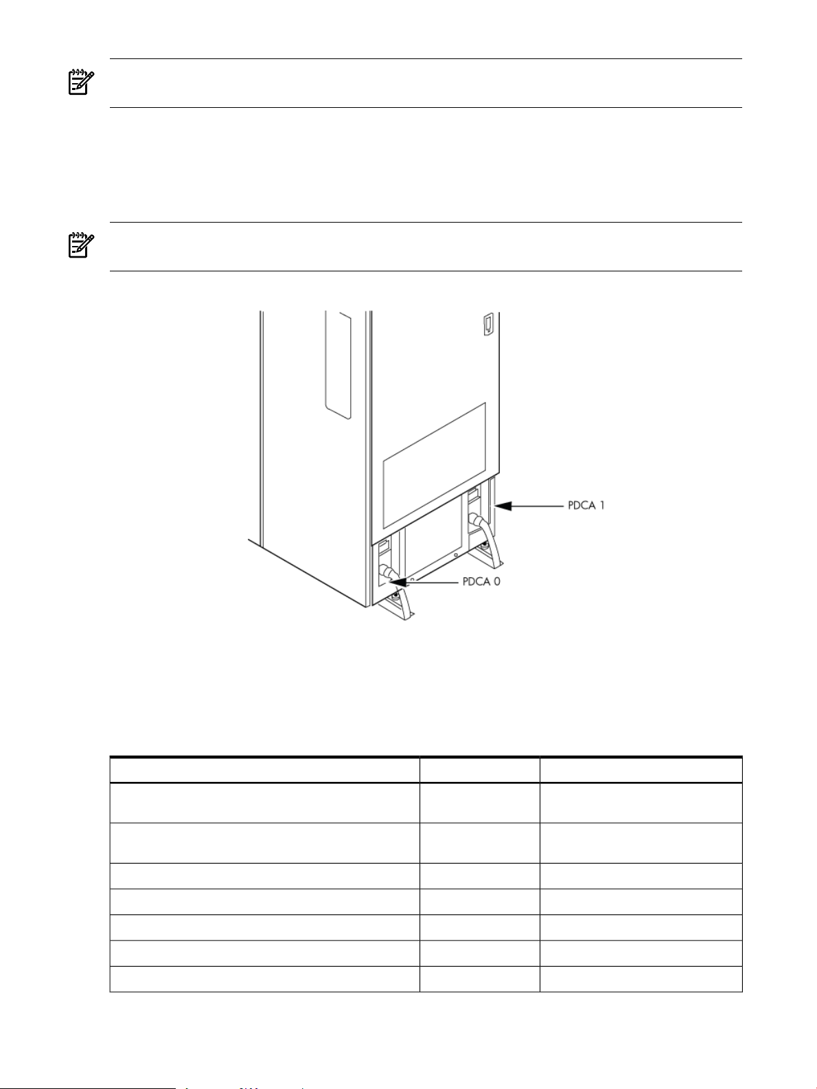
NOTE: A qualified electrician must wire the PDCA receptacle to site power using copper wire
and in compliance with all local codes.
All branch circuits used within a complex must be connected together to form a common ground.
All power sources such as transformers, UPSs, and other sources, must be connected together
to form a common ground.
When only one PDCA is installed in a system cabinet, it must be installed as PDCA 0. For the
location of PDCA 0, see Figure 2-1.
NOTE: When wiring a PDCA, phase rotation is unimportant. When using two PDCAs, however,
the rotation must be consistent for both.
Figure 2-1 PDCA Locations
System Power Requirements
Table 2-8 and Table 2-9 list the ac power requirements for an HP Integrity Superdome/sx2000
system. These tables provide information to help determine the amount of ac power needed for
your computer room.
Table 2-8 Power Requirements (Without SMS)
Nominal input voltage
200/208/220/230/240
V ac rms
200 to 240 V ac rmsInput voltage range (minimum to maximum)
50/60 HzFrequency range (minimum to maximum)
3Number of phases
90 A (peak)Maximum inrush current
CommentsValueRequirement
Autoselecting (measured at input
terminals)
Per-phase at 200 to 240 V ac44 A rmsProduct label maximum current, 3-phase, 4-wire
Per-phase at 200 to 240 V ac24 A rmsProduct label maximum current, 3-phase, 5-wire
52 System Specifications
Page 53

Table 2-8 Power Requirements (Without SMS) (continued)
WARNING! Beware of shock hazard. When connecting or removing input power wiring, always
connect the ground wire first and disconnect it last.
Component Power Requirements
Table 2-9 Component Power Requirements (Without SMS)
Component
1 A number to use for planning, to allow for enough power to upgrade through the life of the system.
CommentsValueRequirement
0.95 minimumPower factor correction
See the following WARNING.> 3.5 mAGround leakage current (mA)
Component Power Required 50 Hz to 60 Hz
8,200 VAMaximum configuration for SD16
12,196 VAMaximum configuration for SD32
900 VACell board
500 VAI/O card cage
1
IOX Cabinet Power Requirements
The IOX requires a single-phase 200-240 V ac input. Table 2-10 lists the ac power requirements
for the IOX cabinet.
NOTE: The IOX accommodates two ac inputs for redundancy.
Table 2-10 I/O Expansion Cabinet Power Requirements (Without SMS)
Table 2-11 I/O Expansion Cabinet Component Power Requirements
ValueRequirement
200/208/220/230/240 V ac rmsNominal input voltage
170-264 V ac rmsInput voltage range (minimum to maximum)
50/60 HzFrequency range (minimum to maximum)
1Number of phases
16 AMarked electrical input current
60 A (peak)Maximum inrush current
0.95 minimumPower factor correction
Component Power Required 50 Hz to 60 HzComponent
IOX Cabinet Power Cords
Table 2-12 lists the power cords for the IOX cabinet.
3200 VAFully configured cabinet
500 VAI/O card cage
600 VAICE
Electrical Specifications 53
Page 54

Table 2-12 I/O Expansion Cabinet ac Power Cords
Environmental Requirements
This section provides the environmental, power dissipation, noise emission, and air flow
specifications.
Temperature and Humidity Specifications
Table 2-13 Operational Physical Environment Requirements
Connector TypeWhere UsedPart Number A5499AZ
L6-20North America-001
IEC 309International-002
1
2
Allowable
15 to 32 (59οto
90οF)
1 The maximum elevation for the operating environment is 3050 meters.
2 Dry bulb temperature is the regular ambient temperature. Derate maximum dry bulb temperature 1˚C/300 m above
3 Must be a noncondensing environment.
4 With installed media, the minimum temperature is 10˚C and maximum relative humidity is limited to 80%. Specific
5 Allowable equipment design extremes as measured at the equipment inlet.
6 Recommended target facility design and operational range.
4,5
900 m.
media requirements can vary.
Recommended
77οF)
6
Relative Humidity % NoncondensingTemperature (Dry BulbοC)
Allowable
5
Recommended
Dew Point
6
3
Rate of Change (˚C/hr,
max)
51740 to 5520 to 8020 to 25 (68οto
Table 2-14 Nonoperational Physical Environment Requirements
Powered Off (Installed)Storage
Temp (˚C, dry
bulb - regular
ambient
temperature)
Rel Hum %;
Noncondensing
Dew point
(max)
Temp (˚C, dry bulb
- regular ambient
temperature)
Rel Hum %
Noncondensing
Dew point
(max)
298 to 905 to 45328 to 90-40 to 60
NOTE: The values in Table 2-14 meet or exceed all ASHRAE specifications.
Power Dissipation
Table 2-15 lists the power requirements by configuration (number of cell boards, amount of
memory per cell, and number of I/O chassis) for the HP Integrity Superdome/sx2000.
The table contains two columns of power numbers expressed in watts. The Breaker Power column
lists the power used to size the wall breaker at the installation site. The Typical Power column
lists typical power. Typical power numbers can be used to assess the average utility cost of
54 System Specifications
Page 55

cooling and electrical power. Table 2-15 also lists the recommended breaker sizes for 4-wire and
5-wire sources.
WARNING! Do not connect a 380 to 415 V ac supply to a 4-wire PDCA. This is a safety hazard
and results in damage to the product. Line-to-line or phase-to-phase voltage measured at 380 to
415 V ac must always be connected using a 5-wire PDCA.
Table 2-15 HP Integrity Superdome/sx2000 Dual-Core CPU Configurations
1
Cells (in
cabinet)
Memory (DIMMs
per cell)
I/O (fully
populated)
(Watts)
Cooling (BTU/Hr)Typical Power
Breaker Power
2
(Watts)
119573238294904328
96012600176202168
10256277768140488
9047245007180288
9601260017620448
8391227266660248
92232497873204166
80132170263602166
8820238867000486
7610206106040286
8417227946680446
7207195185720246
77742105461704164
65641777852102164
7509203375960484
6300170615000284
7257196555760444
6048163794800244
50521368340102162
4901132743890282
4763128983780242
1
Values in Table 2-15 are based on 25 W load I/O cards, 1 GB DIMMs and four Intel® Itanium ® dual-core processors
with 18 MB or 24 MB cache per cell board or four PA-RISC processors with 64 MB.
2 These numbers are valid only for the specific configurations shown. Any upgrades can require a change to the
breaker size. A 5-wire source uses a 4-pole breaker, and a 4-wire source uses a 3-pole breaker. The protective earth
(PE) ground wire is not switched.
Table 2-16 HP Integrity Superdome/sx2000 Single-Core CPU Configurations
Cell (in cabinet)
Memory (DIMMs
per Cell)
I/O (fully
populated)
(Watts)
Cooling (BTU/Hr)Typical Power
1
Breaker Power
(Watts)
115033118191304328
91472479472602168
2
9806265807783488
Environmental Requirements 55
Page 56

Table 2-16 HP Integrity Superdome/sx2000 Single-Core CPU Configurations (continued)
Cell (in cabinet)
Memory (DIMMs
per Cell)
I/O (fully
populated)
(Watts)
Cooling (BTU/Hr)Typical Power
Breaker Power
2
(Watts)
8596233026823288
9147247947260448
7938215166300248
87792379769684166
75702051860082166
8366226776640486
7156193985680286
7969216016325446
6759183225365246
73241985258134164
61141657448532164
5855158704647484
4645125923687284
6781183805382444
1
Values in Table 2-15 are based on 25 W load I/O cards, 1 GB DIMMsand four Intel® Itanium ®single-core processors
with 9 MB cache per cell board.
2 These numbers are valid only for the specific configurations shown. Any upgrades can require a change to the
breaker size. A 5-wire source uses a 4-pole breaker, and a 4-wire source uses a 3-pole breaker. The protective earth
(PE) ground wire is not switched.
Acoustic Noise Specification
The acoustic noise specifications are as follows:
• 8.2 bel (sound power level)
• 65.1 dBA (sound pressure level at operator position)
These levels are appropriate for dedicated computer room environments, not office environments.
You must understand the acoustic noise specifications relative to operator positions within the
computer room when adding HP Integrity Superdome/sx2000 systems to computer rooms with
existing noise sources.
5571151024422244
46061248636562162
4453120693534282
4313116903423242
Airflow
HP Integrity Superdome/sx2000 systems require the cabinet air intake temperature to be between
15οC and 32οC (59οF and 89.6οF) at 2900 CFM.
Figure 2-2 illustrates the location of the inlet and outlet air ducts on a single cabinet.
56 System Specifications
Page 57

NOTE: Approximately 5% of the system airflow draws from the rear of the system and exits
the top of the system.
Figure 2-2 Airflow Diagram
A thermal report for the HP Integrity Superdome/sx2000 server is provided in Table 2-17
(page 57).
Table 2-17 Physical Environmental Specifications
Condition
2
Configuration
Configuration
Configuration
ASHRAE Class
1
Voltage
200–240 V ac
Typical Heat
Release
Nominal Airflow
Airflow at
1,2
32oC
Configuration
Configuration
Configuration
WeightMaximum
2 Cell, 4 DIMM, 2 I/OMinimum
3
8 Cell, 32 DIMM, 4 I/OMaximum
3
6 Cell, 16 DIMM, 4 I/OTypical
3
Overall System
Dimensions
(W X D X H)
mminkgpoundsm3/hrCFMm3/hrCFMWattsDescription
76.2x121.9x195.630x48x77.2420.3926.35.029005.029003423Minimum
76.2x121.9x195.630x48x77.2563.21241.25.029005.029009130Maximum
76.2x121.9x195.630x48x77.2515.11135.25.029005.029006968Typical
Environmental Requirements 57
Page 58

1 Derate maximum dry bulb temperature 1oC/300 m above 900 m.
2 The system deviates slightly from front to top and rear airflow protocol. Approximately 5 percent of the system
airflow is drawn in from the rear of the system. See Figure 2-2 (page 57) for more details.
3 See Table 2-15 (page 55) and Table 2-16 (page 55) for additional details regarding minimum, maximum, and typical
configurations.
58 System Specifications
Page 59

3 Installing the System
This chapterdescribes installationof HP Integrity Superdome/sx2000 and HP 9000/sx2000 systems.
Installers must have received adequate training, be knowledgeable about the product, and have
a good overall background in electronics and customer hardware installation.
Introduction
The instructions in this chapter are written for Customer Support Consultants (CSC) who are
experienced at installing complex systems. This chapter provides details about each step in the
sx2000 installation process. Some steps must be performed before others can be completed
successfully. To avoid undoing and redoing an installation step, follow the installation sequences
outlined in this chapter.
Communications Interference
HP system compliance tests are conducted with HP supported peripheral devices and shielded
cables, such as those received with the system. The system meets interference requirements of
all countries in which it is sold. These requirements provide reasonable protection against
interference with radio and television communications.
Installing and using the system in strict accordance with instructions provided by HP minimizes
the chances that the system will cause radio or television interference. However, HP does not
guarantee that the system will not interfere with radio and television reception.
Take the following precautions:
• Use only shielded cables.
• Install and route the cables according to the instructions provided.
• Ensure that all cable connector screws are firmly tightened.
• Use only HP supported peripheral devices.
• Ensure that all panels and cover plates are in place and secure before turning on the system.
Electrostatic Discharge
HP systems and peripherals contain assemblies and components that are sensitive to electrostatic
discharge (ESD).
CAUTION: Carefully observe the precautions and recommended procedures in this document
to prevent component damage from static electricity.
Take the following precautions:
• Always wear a grounded wrist strap when working on or around system components.
• Treat all assemblies, components, and interface connections as static-sensitive.
• When unpacking cards, interfaces, and other accessories that are packaged separately from
the system, keep the accessories in their non-conductive plastic bags until you are ready to
install them.
• Before removing or replacing any components or installing any accessories in the system,
select a work area in which potential static sources are minimized, preferably an antistatic
work station.
• Avoid working in carpeted areas and keep body movement to a minimum while installing
accessories.
Introduction 59
Page 60

Public Telecommunications Network Connection
Instructions are issued to the installation site that modems cannot be connected to public
telecommunications networks until full datacomm licenses are received for the country of
installation. Some countries do not require datacomm licenses. Theproduct regulations engineer
must review beta site locations, and if datacomm licenses are not complete, ensure that the
installation site is notified officially and in writing that the product cannot be connected topublic
telecommunications networks until the license is received.
Unpacking and Inspecting the System
This section describes what to do before unpacking the server and how to unpack the system
itself.
WARNING! Do not attempt to move the cabinet, packed or unpacked, up or down an incline
of more than 15 degrees.
Verifying Site Preparation
Verifying site preparation includes gathering LAN information and verifying electrical
requirements.
Gathering LAN Information
The Support Management Station (SMS) connects to the customer’s LAN. Determine the
appropriate IP address.
Verifying Electrical Requirements
The site must be verified for proper grounding and electrical requirements prior to the system
being shipped to the customer as part of the site preparation. Before unpacking and installing
the system, verify with the customer that grounding specifications and power requirements are
met.
Checking the Inventory
The sales order packing slip lists all equipment shipped from HP. Use this packing slip to verify
that all equipment has arrived at the customer site.
NOTE: To identify each item by part number, see the sales order packing slip.
One of the large overpack containers is labeled “Open Me First.” This box contains the Solution
Information Manual and DDCAs. The unpacking instructions are in the plastic bag taped to the
cabinet.
The following items are in other containers. Check them against the packing list:
• Power distribution control assembly (PDCA) and power cord
• Two blower housings per cabinet
• Four blowers per cabinet
• Four side skins with related attachment hardware
• Cabinet blower bezels and front door assemblies
• Support Management Station
• Cables
• Optional equipment
• Boot device with the operating system installed
60 Installing the System
Page 61

Inspecting the Shipping Containers for Damage
HP shipping containers are designed to protect their contents under normal shipping conditions.
After the equipment arrives at the customer site, carefully inspect each carton for signs of shipping
damage.
WARNING! Do not attempt to move the cabinet, packed or unpacked, up or down an incline
of more than 15 degrees.
A tilt indicator is installed on the back and side of the cabinet shipping container (Figure 3-1
(page 61)). If the container is tilted to an angle that can cause equipment damage, the beads in
the indicator shift positions (Figure 3-2 (page 62)). If a carton has received a physical shock and
the tilt indicator is in an abnormal condition, visually inspect the unit for any signs of damage.
If damage is found, document the damage with photographs and contact the transport carrier
immediately.
Figure 3-1 Normal Tilt Indicator
Unpacking and Inspecting the System 61
Page 62

Figure 3-2 Abnormal Tilt Indicator
NOTE: If the tilt indicator shows that an abnormal shipping condition has occurred, write
“possible hidden damage” on the bill of lading and keep the packaging.
Inspection Precautions
• When the shipment arrives, check each container against the carrier's bill of lading. Inspect
the exterior of each container immediately for mishandling or damage during transit. If any
of the containers are damaged, request the carrier's agent be present when the container is
opened.
• When unpacking the containers, inspect each item for external damage. Look for broken
controls and connectors, dented corners, scratches, bent panels, and loose components.
NOTE: HP recommends keeping the shipping container and the packaging material. If it
becomes necessary to repackage the cabinet, the original packing material is necessary.
If discarding the shipping container or packaging material, dispose of them in an environmentally
responsible manner (recycle, if possible).
Claims Procedures
If the shipment is incomplete, if the equipment is damaged, or it fails to meet specifications,
notify the nearest HP Sales and Service Office. If damage occurred in transit, notify the carrier
as well.
HP will arrange for replacement or repair without waiting for settlement of claims against the
carrier. In the event of damage in transit, retain the packing container and packaging materials
for inspection.
Unpacking and Inspecting Hardware Components
This section describes the procedures for opening the shipping container and unpacking and
inspecting the cabinet.
62 Installing the System
Page 63

Tools Required
The following tools are required to unpack and install the system:
• Standard hand tools, such as a adjustable-end wrench
• ESD grounding strap
• Digital voltmeter capable of reading ac and dc voltages
• 1/2-inch socket wrench
• 9/16-inch wrench
• #2 Phillips screwdriver
• Flathead screwdriver
• Wire cutters or utility knife
• Safety goggles or glasses
• T-10, T-15, T-20, T-25, and T-30 Torx drivers
• 9-pin to 25-pin serial cable (HP part number 24542G)
• 9-pin to 9-pin null modem cable
Unpacking the Cabinet
WARNING! Use three people to unpack the cabinet safely.
HP recommends removing the cardboard shipping container before moving the cabinet into the
computer room.
NOTE: If unpacking the cabinet in the computer room, be sure to position it so that it can be
moved into its final position easily. Notice that the front of the cabinet (Figure 3-3) is the side
with the label showing how to align the ramps.
To unpack the cabinet, follow these steps:
Unpacking and Inspecting the System 63
Page 64

1. Position the packaged cabinet so that a clear area about three times the length of the package
(about 12 feet or 3.66 m) is available in front of the unit, and at least 2 feet (0.61 m) are
available on the sides.
Figure 3-3 Front of Cabinet Container
WARNING! Do not stand directly in front of the strapping while cutting it. Hold the band
above the intended cut and wear protective glasses. These bands are under tension. When
cut, they spring back and can cause serious eye injury.
2. Cut the plastic polystrap bands around the shipping container (Figure 3-4 (page 64)).
Figure 3-4 Cutting the Polystrap Bands
64 Installing the System
Page 65

3. Lift the cardboard corrugated top cap off the shipping box.
4. Remove the corrugated sleeves surrounding the cabinet.
CAUTION: Cut the plastic wrapping material off rather than pulling it off. Pulling the
plastic covering off creates an ESD hazard to the hardware.
5. Remove the stretch wrap, the front and rear top foam inserts, and the four corner inserts
from the cabinet.
6. Remove the ramps from the pallet and set them aside (Figure 3-5 (page 65)).
Figure 3-5 Removing the Ramps from the Pallet
Unpacking and Inspecting the System 65
Page 66

7. Remove the plastic antistatic bag by lifting it straight up off the cabinet. If the cabinet or any
components are damaged, follow the claims procedure. Some damage can be repaired by
replacing the damaged part. If you find extensive damage, you might need to repack and
return the entire cabinet to HP.
Inspecting the Cabinet
To inspect the cabinet exterior for signs of shipping damage, follow these steps:
1. Look at the top and sides for dents, warping, or scratches.
2. Verify that the power supply mounting screws are in place and locked (Figure 3-6).
Figure 3-6 Power Supply Mounting Screws Location
3. Verify that the I/O chassis mounting screws are in place and secure (Figure 3-7).
Inspect all components for signs of shifting during shipment or any signs of damage.
Figure 3-7 I/O Chassis Mounting Screws
66 Installing the System
Page 67

Unpacking and Inspecting the System 67
Page 68

Moving the Cabinet Off the Pallet
1. Remove the shipping strap that holds the BPSs in place during shipping (Figure 3-8
(page 68)).
Failure to remove the shipping strap will obstruct air flow into the BPS and FEPS.
Figure 3-8 Shipping Strap Location
2. Remove the pallet mounting brackets and pads on the side of the pallet where the ramp
slots are located (Figure 3-9).
68 Installing the System
Page 69

Figure 3-9 Removing the Mounting Brackets
WARNING! Do not remove the bolts on the mounting brackets that attach to the pallet.
These bolts prevent the cabinet from rolling off the back of the pallet.
3. On the other side of the pallet, remove only the bolt on each mounting bracket that is attached
to the cabinet.
4. Insert the ramps into the slots on the pallet.
CAUTION: Make sure the ramps are parallel and aligned (Figure 3-10).
The casters on the cabinet must roll unobstructed onto the ramp.
Unpacking and Inspecting the System 69
Page 70
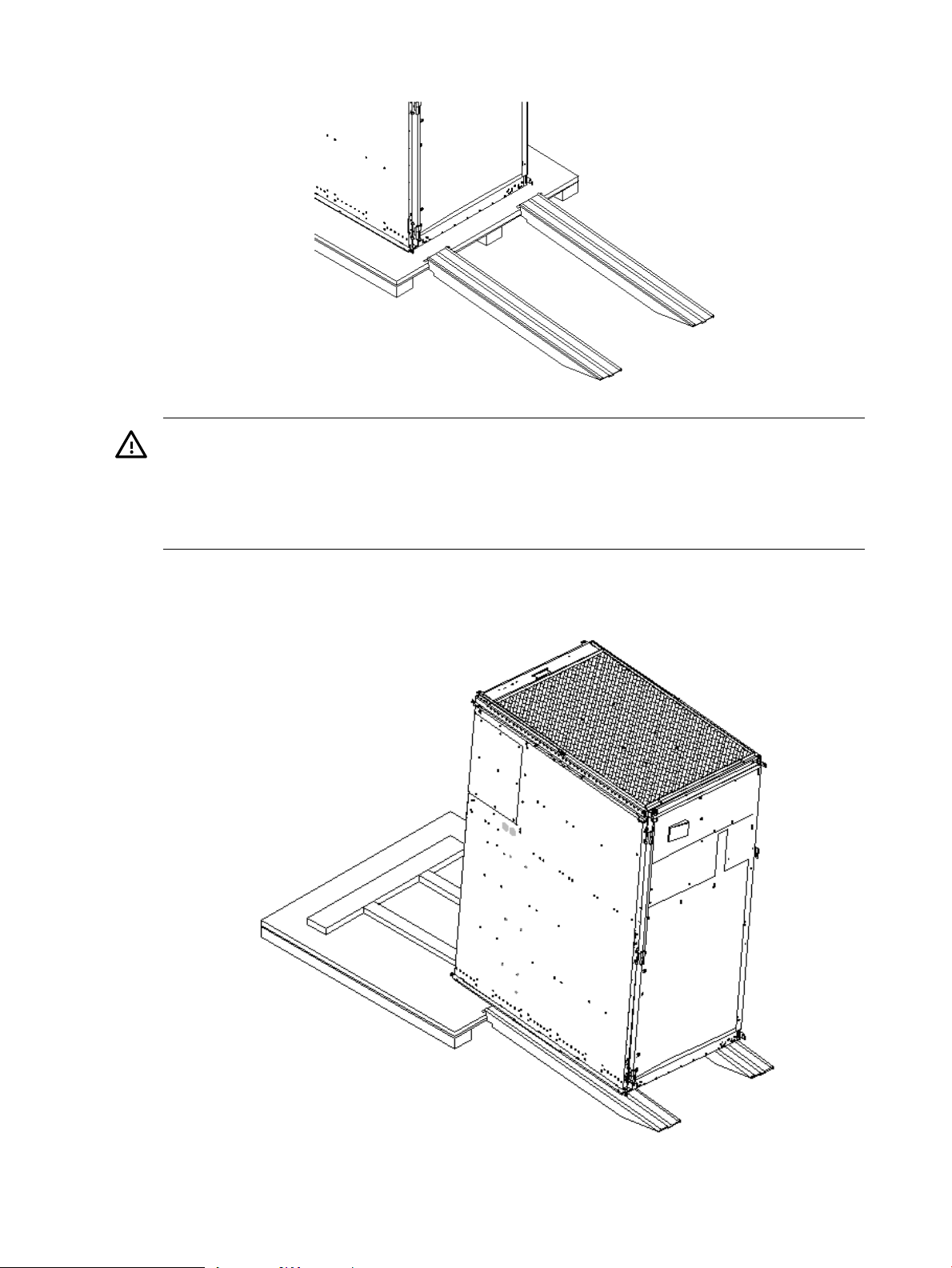
Figure 3-10 Positioning the Ramps
WARNING! Do not attempt to roll a cabinet without help. The cabinet can weigh as
much as 1400 pounds (635 kg). Three people are required to roll the cabinet off the pallet.
Position one person at the rear of the cabinet and one person on each side.
WARNING! Do not attempt to move the cabinet, either packed or unpacked, up or down
an incline of more than 15 degrees.
5. Carefully roll the cabinet down the ramp (Figure 3-11).
Figure 3-11 Rolling the Cabinet Down the Ramp
6. Unpack any other cabinets that were shipped.
70 Installing the System
Page 71

Unpacking the PDCA
At least one PDCA ships with the system. In some cases, the customer might order two PDCAs,
the second to be used as a backup power source. Unpack the PDCA and ensure it has the power
cord option for installation.
Several power cord options are available for the PDCAs. Only options 6 and 7 are currently
available in new system configurations (Table 3-1 (page 71)). Table 3-2 (page 71) details options
6 and 7.
Table 3-1 Available Power Options
Option
1 A dedicated branch circuit is required for each PDCA installed.
Source
Type
3-phase6
3-phase7
Source Voltage
(Nominal)
240 V ac,
phase-to-phase, 50 Hz
/ 60 Hz
240 V ac,
phase-to-neutral, 50Hz
/ 60 Hz
PDCA
Required
4-wireVoltage range 200 to
5-wireVoltage range 200 to
Phase 200 to 240 V
ac
44 A maximum per
phase
24 A maximum per
phase
Table 3-2 Power Cord Option 6 and 7 Details
A5201-69023 (Option
6)
A5201-69024 (Option
7)
OLFLEX 190 (PN 600804) is a 2.5 meter
multiconductor, 600 V, 90˚C, UL and CSA
approved, oil resistant flexible cable. (8
AWG 60 A capacity)
H07RN-F (OLFLEX PN 1600130) is a 2.5
meter heavy-duty neoprene jacketed
harmonized European flexible cable. (4
mm232 A capacity)
1
Mennekes ME 460P9
(60 A capacity)
Mennekes ME
532P6-14 (32 A
capacity)
Power Receptacle RequiredInput Current Per
Connector and plug provided
with a 2.5 m (8.2 feet) power
cable. An electrician must
hardwire receptacle to 60 A site
power.
Connector and plug provided
with a 2.5 m (8.2 feet) power
cable. An electrician must
hardwire receptacle to 32 A site
power.
Receptacle RequiredAttached PlugAttached Power CordPDCA Part Number
Mennekes ME460R9 (60
A capacity)
Mennekes ME
532R6-1500 (32 A
capacity)
Returning Equipment
If the equipment is damaged, use the original packing material to repackage the cabinet for
shipment. If the packing material is not available, contact the local HP Sales and Support Office
regarding shipment.
Before shipping, place a tag on the container or equipment to identify the owner and the service
to be performed. Include the equipment model number and the full serial number, if applicable.
The model number and the full serial number are printed on the system information labels located
at the bottom front of the cabinet.
WARNING! Do not attempt to push the loaded cabinet up the ramp onto the pallet. Three
people are required to push the cabinet up the ramp and position it on the pallet. Inspect the
condition of the loading and unloading ramp before use.
Repackaging
To repackage the cabinet, follow these steps:
1. Assemble the HP packing materials that came with the cabinet.
2. Carefully roll the cabinet up the ramp.
3. Attach the pallet mounting brackets to the pallet and the cabinet.
Unpacking and Inspecting the System 71
Page 72

4. Reattach the ramps to the pallet.
5. Replace the plastic antistatic bag and foam inserts.
6. Replace the cardboard surrounding the cabinet.
7. Replace the cardboard caps.
8. Secure the assembly to the pallet with straps.
The cabinet is now ready for shipment.
Setting Up the System
After a site is prepared, the system is unpacked, and all components are inspected, the system
can be prepared for booting.
Moving the System and Related Equipment to the Installation Site
Carefully move the cabinets and related equipment to the installation site but not into the final
location. If the system is to be placed at the end of a row, you must add side bezels before
positioning the cabinet in its final location. Check the path from where the system was unpacked
to its final destination to make sure the way is clear and free of obstructions.
WARNING! If the cabinet must be moved up ramps, be sure to maneuver it using three people.
Unpacking and Installing the Blower Housings and Blowers
Each cabinet contains two blower housings and four blowers. Although similar in size, the blower
housings for each cabinet are not the same; one has a connector to which the other attaches. To
unpack and install the housings and blowers, follow these steps:
1. Unpack the housings from the cardboard box and set them aside.
The rear housing is labeled Blower 3 Blower 2. The front housing is labeled Blower 0 Blower
1.
CAUTION: Do not lift the housing by the frame (Figure 3-12).
Figure 3-12 Blower Housing Frame
72 Installing the System
Page 73

2. Remove the cardboard from the blower housing (Figure 3-13).
This cardboard protects the housing baffle during shipping. If it is not removed, the fans
can not work properly.
Figure 3-13 Removing Protective Cardboard from the Housing
NOTE: Double-check that the protective cardboard has been removed.
3. Using the handles on the housing labeled Blower 3 Blower 2, align the edge of the housing
over the edge at the top rear of the cabinet, and slide it into place until the connectors at the
back of each housing are fully mated (Figure 3-14). Then tighten the thumbscrews at the
front of the housing.
Figure 3-14 Installing the Rear Blower Housing
Setting Up the System 73
Page 74
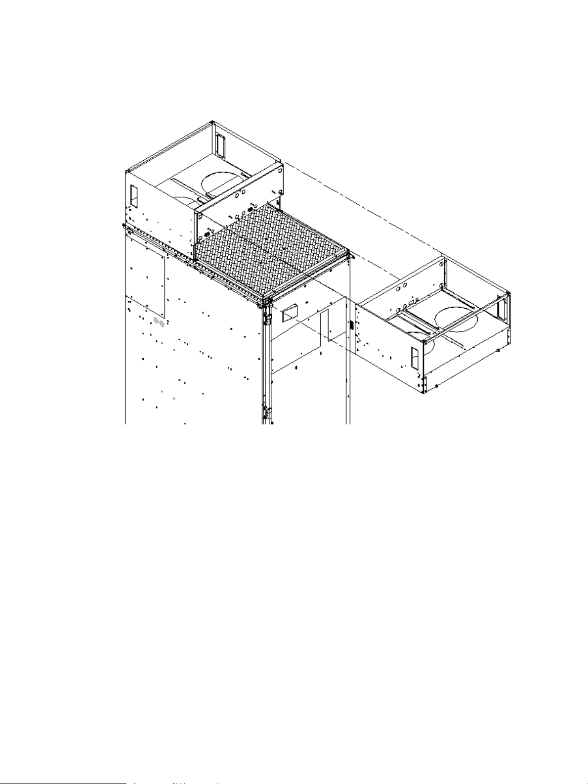
4. Using the handles on the housing labeled Blower 0 Blower 1, align the edge of the housing
over the edge at the top front of the cabinet, and slide it into place until the connectors at
the back of each housing are fully mated (Figure 3-15). Then tighten the thumbscrews at the
front of the housing.
Figure 3-15 Installing the Front Blower Housing
5. Unpack each of the four blowers.
6. Insert each of the four blowers into place in the blower housings with the thumbscrews at
the bottom (Figure 3-16).
74 Installing the System
Page 75

Figure 3-16 Installing the Blowers
7. Tighten the thumbscrews at the front of each blower.
8. If required, install housings on any other cabinets that were shipped with the system.
Attaching the Side Skins and Blower Side Bezels
Two cosmetic side panels affix to the left and right sides of the system. In addition, each system
has bezels that cover the sides of the blowers.
IMPORTANT: Be sure to attach the side skins at this point inthe installation sequence, especially
if the cabinet is to be positioned at the end of a row of cabinets or between cabinets.
Attaching the Side Skins
Each system has four side skins: two front-side skins and two rear-side skins.
NOTE: Attach side skins to the left side of cabinet 0 and the right side of cabinet 1 (if applicable).
To attach the side skins, follow these steps:
1. If not already done, remove the side skins from their boxes and protective coverings.
2. From the end of the brackets at the back of the cabinet, position the side skin with the lap
joint (Rear) over the top bracket and under the bottom bracket, and gently slide it into position
(Figure 3-17).
Two skins are installed on each side of the cabinet: one has a lap joint (Rear) and one does
not (Front). The side skins with the lap joint are marked Rear and the side skins without the
lap joint are marked Front.
Setting Up the System 75
Page 76
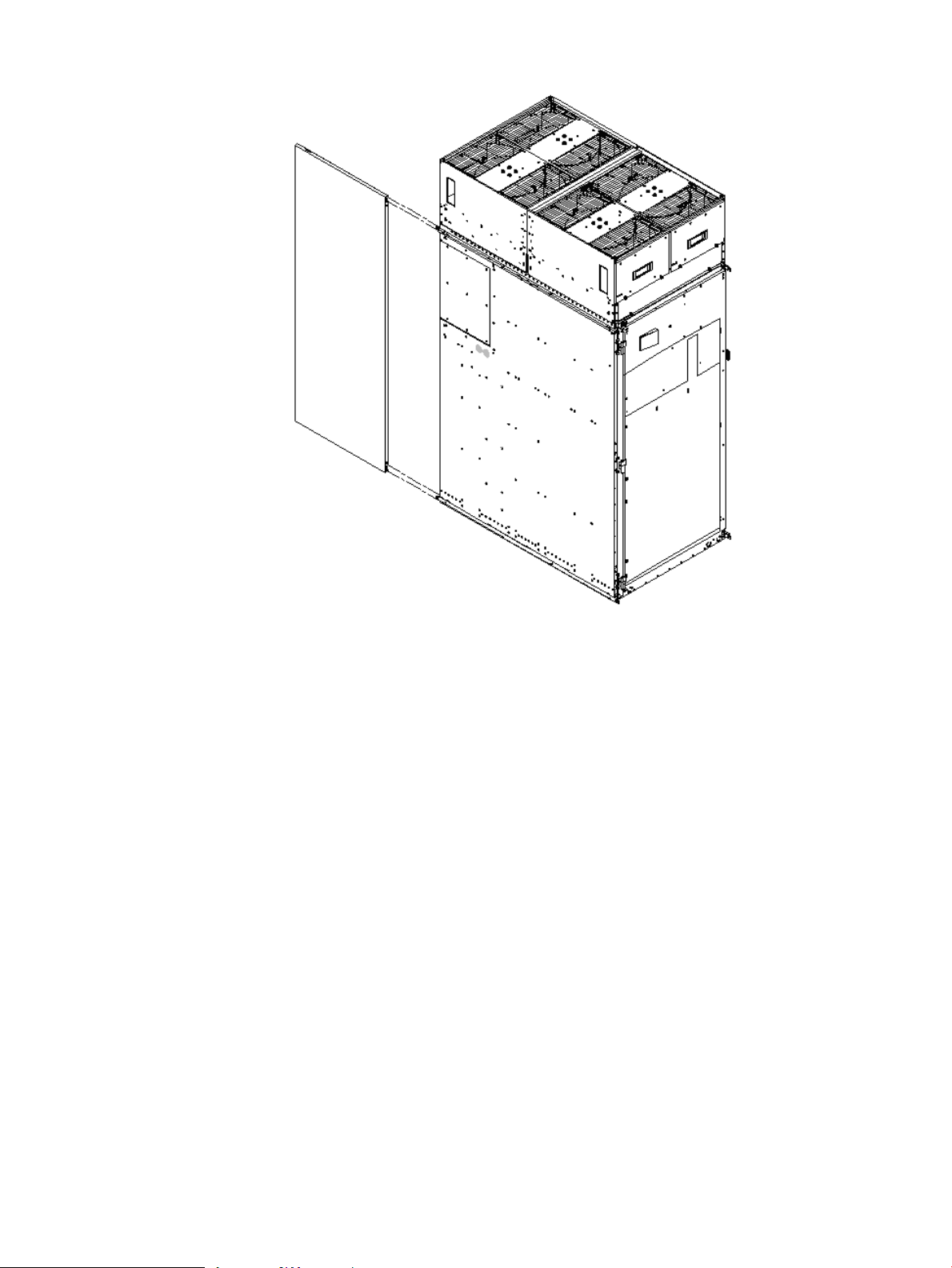
Figure 3-17 Attaching the Rear Side Skin
3. Attach the skin without the lap joint (Front) over the top bracket and under the bottom bracket
and gently slide the skin into position.
76 Installing the System
Page 77
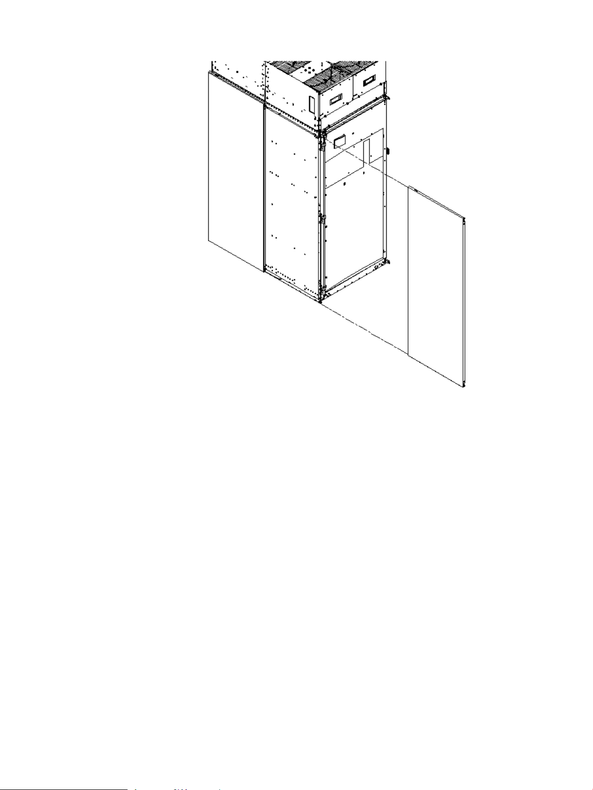
Figure 3-18 Attaching the Front Side Skins
4. Push the side skins together, making sure the skins overlap at the lap joint.
Attaching the Blower Side Bezels
The bezels are held on at the top by the bezel lip, which fits over the top of the blower housing
frame, and are secured at the bottom by tabs that fit into slots on the cabinet side panels
(Figure 3-19).
Use the same procedure to attach the right and left blower side bezels.
Setting Up the System 77
Page 78
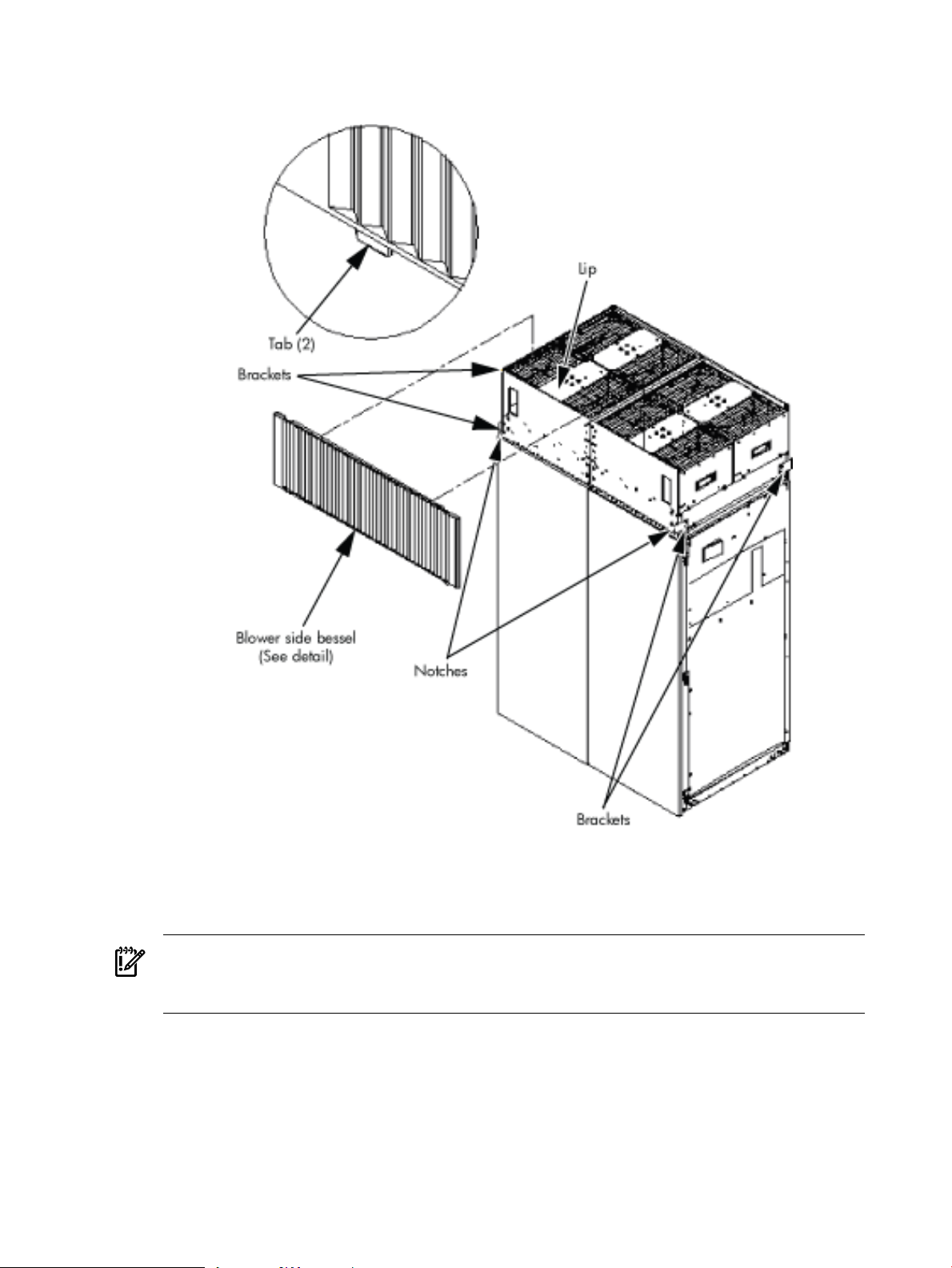
1. Place the side bezel slightly above the blower housing frame.
Figure 3-19 Attaching the Side Bezels
2. Align the lower bezel tabs to the slots in the side panels.
3. Lower the bezel so the bezel top lip fits securely on the blower housing frame and the two
lower tabs are fully inserted into the side panel slots.
IMPORTANT: Use four screws to attach the side skins to the top and bottom brackets, except
for the top bracket on the right side (facing the front of the cabinet). Do not attach the rear
screw on that bracket. Insert all screws but do not tighten until all side skins are aligned.
4. Using a T-10 driver, attach the screws to secure the side skins to the brackets.
5. Repeat step 1 through step 4 for the skins on the other side of the cabinet.
6. To secure the side bezels to the side skins, attach the blower bracket locks (HP part number
A5201-00268) to the front and back blowers using a T-20 driver.
There are two blower bracket locks on the front blowers and two on the rear.
78 Installing the System
Page 79

Attaching the Leveling Feet and Leveling the Cabinet
After positioning the cabinet in its final location, to attach and adjust the leveling feet, follow
these steps:
1. Remove the leveling feet from their packages.
2. Attach the leveling feet to the cabinet using four T-25 screws.
Figure 3-20 Attaching the Leveling Feet
3. Screw down each leveling foot clockwise until it is in firm contact with the floor. Adjust
each foot until the cabinet is level.
Installing the Front Door Bezels and the Front and Rear Blower Bezels
Each cabinet has two doors, one at the front and one at the back. The back door is shipped on
the chassis and requires no assembly. The front door, which is also shipped on the chassis,
requires the assembly of two plastic bezels to its front surface and a cable from the door to the
upper front bezel. In addition, you must install bezels that fit over the blowers at the front and
back of the cabinet.
Installing the Front Door Bezels
The front door assembly includes two cosmetic covers, a control panel, and a key lock. To install
the front door, you must connect the control panel ribbon cable from the chassis to the control
panel and mount the two plastic bezels onto the metal chassis door.
IMPORTANT: The procedure in this section requires two people and must be performed with
the front metal chassis door open.
To install the front door assembly, follow these steps:
1. Open the front door, unsnap the screen, and remove all the filters held in place with Velcro.
2. Remove the cabinet keys that are taped inside the top front door bezel.
3. Insert the shoulder studs on the lower door bezel into the holes on the front door metal
chassis (Figure 3-21).
Setting Up the System 79
Page 80

Figure 3-21 Installing the Lower Front Door Assembly
4. Using a T-10 driver, secure the lower door bezel to the front door chassis with 10 of the
screws provided. Insert all screws loosely, then tighten them after the bezel is aligned.
5. While another person holds the upper door bezel near the door chassis, attach the ribbon
cable to the back of the control panel on the bezel and tighten the two flathead screws
(Figure 3-22).
80 Installing the System
Page 81

Figure 3-22 Installing the Upper Front Door Assembly
6. Feed the grounding strap through the door and attach it to the cabinet.
7. Insert the shoulder studs on the upper door bezel into the holes on the front door metal
chassis.
8. Using a T-10 driver, secure the upper door bezel to the metal door with eight of the screws
provided. Be sure to press down on the hinge side of the bezel while tightening the screws
to prevent misalignment of the bezel.
9. Reattach all filters removed in step 1.
Installing the Rear Blower Bezel
The rear blower bezel is a cosmetic cover for the blowers and is located above the rear door.
To install the rear blower bezel, follow these steps:
1. Open the rear cabinet door.
NOTE: The latch is located on the right side of the door.
2. Slide the bezel over the blower housing frame, hooking the lip of the bezel onto the cross
support of the blower housing while holding the bottom of the bezel. Rotate the bezel
downward from the top until the bottom snaps in place (Figure 3-23 (page 82)).
Setting Up the System 81
Page 82

Figure 3-23 Installing the Rear Blower Bezel
3. Align the bezel over the nuts that are attached to the bracket at the rear of the cabinet.
4. Using a T-20 driver, tighten the two captive screws on the lower flange of the bezel.
NOTE: Tighten the screws securely to prevent them from interfering with the door.
5. Close the cabinet rear door.
Installing the Front Blower Bezel
The front blower bezel is a cosmetic cover for the blowers and is located above the front door.
To install the front blower bezel, follow these steps:
1. Open the front door.
NOTE: The latch is located on the right side of the front door.
2. Position the bezel over the blower housing frame, hooking the lip of the bezel onto the cross
support of the blower housing (Figure 3-24 (page 83)).
82 Installing the System
Page 83

Figure 3-24 Installing the Front Blower Bezel
3. Align the bezel over the nuts that are attached to the bracket at the front of the cabinet.
4. Using a T-20 driver, tighten the two captive screws on the lower flange of the bezel.
NOTE: Tighten the screws securely to prevent them from interfering with the door.
5. Close the front door.
Wiring Check
WARNING! LETHAL VOLTAGE HAZARD—Hazardous voltages canbe present inthe cabinet
if incorrectly wired into the site AC power supply. Always verify correct wiring and product
grounding before applying AC power to the cabinet. Failure to do so can result in injury to
personnel and damage to equipment.
Verify the following items before applying AC power to the cabinet:
• Cabinet safety ground connects to the site electrical system ground and is not left floating
or connected to a phase.
• The minimum required method of grounding is to connect the green power cord safety
ground to the site ground point through the power cord receptacle wiring. HP does not
recommend cabinet grounding. Treat cabinet grounding as auxiliary or additional grounding
over and above the ground wire included within the supplied power cord.
If the product ground is left floating, anyone coming into contact with the cabinet can receive a
lethal shock if a component fails and causes leakage or direct connection of phase energy to the
cabinet.
If the product ground connects to a phase, the server is over 200 volts above ground, presenting
a lethal shock hazard to anyone coming into contact with the product when site AC power is
applied to the product.
Verify the connection of the product ground to site AC power ground through a continuity check
between the cabinet and site AC power supply ground. Perform the continuity check while the
site AC power supply circuit breakers serving the cabinet and the cabinet circuit breaker are all
set to OFF.
Setting Up the System 83
Page 84

To verify that the product ground connects to the site AC power supply ground, follow these
steps:
1. Ensure that the site AC power supply circuit breakers serving the cabinet are set to OFF.
2. Ensure that the cabinet main circuit breaker is set to OFF.
3. Touch one test probe to the site AC power supply ground source.
4. Touch the other test probe to an unpainted metal surface of the cabinet.
NOTE: If the digital multimeter (DMM) leads can not reach from the junction box to the
cabinet, use a piece of wire connected to the ground terminal of the junction box.
5. Check for continuity indication of less than 0.1 ohm.
• If continuity is not found, check to ensure that the DMM test leads are making good
contact to unpainted metal and try again.
• If continuity is still not found, disconnect the cabinet site AC power immediately and
notify the customer of the probability of incorrectly wired AC power to the cabinet.
• If continuity is good, and connection of the cabinet to site AC power supply ground
(and not floating or connected to a phase) is verified, then check the voltage.
NOTE: For dual power sources, proceed to “Checking Voltage” (page 88) with special attention
to PDCA 0 ground pin to PDCA 1 ground pin voltage. Anything greater than 3 V is cause for
further investigation.
Installing and Verifying the PDCA
All systems are delivered with the appropriate cable plug for options 6 and 7 (Figure 3-25
(page 85)).
Check the voltages at the receptacle prior to plugging in the PDCA plug.
• To verify the proper wiring for a 4-wire PDCA, use a digital voltmeter (DVM) to measure
the voltage at the receptacle. Voltage must read 200–240 V ac phase-to-phase as measured
between the receptacle pins as follows: L1 to L2, L2 to L3, L1 to L3 (Figure 3-26 (page 85)).
• To verify the proper wiring for a 5-wire PDCA, use a DVM to measure the voltage at the
receptacle. Voltage must read 200–240 V ac phase-to-neutral as measured between the
receptacle pins as follows: L1 to N, L2 to N, L3 to N (Figure 3-27 (page 86)).
84 Installing the System
Page 85

Figure 3-25 PDCA Assembly for Options 6 and 7
Figure 3-26 A 4-Wire Connector
Setting Up the System 85
Page 86

Figure 3-27 A 5-Wire Connector
To install the PDCA, follow these steps:
WARNING! Make sure the circuit breaker on the PDCA is OFF.
1. Remove the rear PDCA bezel by removing the four retaining screws.
2. Run the power cord down through the appropriate opening in the floor tile.
3. Insert the PDCA into its slot (Figure 3-28 (page 86)).
Figure 3-28 Installing the PDCA
4. Using a T-20 driver, attach the four screws that hold the PDCA in place.
5. If required, repeat step 2 through step 4 for the second PDCA.
86 Installing the System
Page 87

6. Reinstall the rear PDCA bezel.
CAUTION: Do not measure voltages with the PDCA breaker set to ON. Make sure the
electrical panel breaker is ON and the PDCA breaker is OFF.
7. Plug in the PDCA connector.
8. Check the voltage at the PDCA:
a. Using a T-20 driver, remove the screw on the hinged panel at the top of the PDCA.
(Figure 3-29).
b. Using a voltmeter, measure the test points and compare the values to the ranges given
in Table 3-3 (page 87) to make sure the voltages conform to the specifications for the
PDCA and local electrical specifications.
If the voltage values do not match the specifications, have the customer contact an
electrician to troubleshoot the problem.
Figure 3-29 Checking PDCA Test Points (5-Wire)
Table 3-3 4- and 5-Wire Voltage Ranges
5-Wire4-Wire
L1 to N: 200-240 VL2 to L3: 200-240 V
L2 to N: 200-240 VL2 to L1: 200-240 V
L3 to N: 200-240 VL1 to L3: 200-240 V
N to Ground:
1 Neutral to ground voltage can vary from millivolts to several volts depending on the distance to the ground/neutral
bond at the transformer. Any voltage over 3 V must be investigated by a site preparation or power specialist.
1
Setting Up the System 87
Page 88

Checking Voltage
The voltage check ensures that all phases (and neutral, for international systems) are wired
correctly for the cabinet and that the AC input voltage is within specified limits.
NOTE: If you use a UPS, see applicable UPS documentation for information to connect the
server and to check the UPS output voltage. UPS User Manual documentation is shipped with
the UPS and is available at http://docs.hp.com.
1. Verify that site power is OFF.
2. Open the site circuit breakers.
3. Verify that the receptacle ground connector is connected to ground. See Figure 3-30 for
connector details.
4. Set the site power circuit breaker to ON.
Figure 3-30 Wall Receptacle Pinouts
5. Verify that the voltage between receptacle pins x and y is 200–240 volts ac.
6. Set the site power circuit breaker to OFF.
7. Ensure that power is removed from the server.
8. Route and connect the server power connector to the site power receptacle.
• For locking type receptacles, line up the key on the plug with the groove in the receptacle.
• Push the plug into the receptacle and rotate to lock the connector in place.
WARNING! Do not set site ac circuit breakers serving the processor cabinets to ON before
verifying that the cabinet has been wired into the site ac power supply correctly. Failure to
do so can result in injury to personnel or damage to equipment when ac power is applied
to the cabinet.
9. Set the site power circuit breaker to ON.
WARNING! There is a risk of shock hazard while testing primary power. Use properly
insulated probes. Be sure to replace the access cover when you finish testing primary power.
10. Set the server power to ON.
88 Installing the System
Page 89
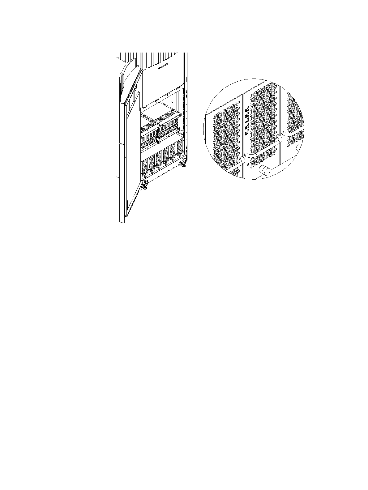
11. Check that the indicator LED on each power supply is lit. See Figure 3-31.
Figure 3-31 Power Supply Indicator LED
Removing the EMI Panels
Remove the front and back electromagnetic interference (EMI) panels to access ports and to
visually check whether components are in place and the LEDs are properly illuminated when
power is applied to the system.
To remove the front and back EMI panels, follow these steps:
Setting Up the System 89
Page 90

1. Using a T-20 driver, loosen the captive screw at the top center of the front EMI panel
(Figure 3-32).
Figure 3-32 Removing Front EMI Panel Screw
2. Use the handle provided to remove the EMI panel and set it aside.
When in position, the EMI panels (front and back) are tightly in place. Removing them takes
controlled but firm exertion.
3. Loosen the captive screw at the lower center of the back EMI panel (Figure 3-33 (page 90)).
Figure 3-33 Removing the Back EMI Panel
4. Use the handle provided to gently remove the EMI panel and set it aside.
90 Installing the System
Page 91

Connecting the Cables
The I/O cables are attached and tied inside the cabinet. When the system is installed, these cables
must be untied, routed, and connected to the cabinets where the other end of the cables terminate.
Use the following guidelines and Figure 3-34 to route and connect cables. For more information
on cable routing, see “Routing the I/O Cables” (page 91).
• Each cabinet is identified with a unique color. The cabinet color label is located at the top
of the cabinet.
• The colored label closest to the cable connector corresponds to the color of the cabinet to which
it is attached.
• The colored label farther away from the cable connector corresponds to the color of the
cabinet where the other end of the cable is attached. In Figure 3-34, the dotted lines show
where the label is located and where the cable terminates.
• Each cable is also labeled with a unique number. This number label is applied on both ends
of the cable and near the port where the cable is to be connected. In Figure 3-34, the cable
number labels are indicated by circled numbers, and the cabinet port numbers are indicated
with boxed numbers.
Figure 3-34 Cable Labeling
Routing the I/O Cables
Routing the cables is a significant task in the installation process. Efficient cable routing is
important not only for the initial installation, but also to aid in future service calls. The most
efficient use of space is to route cables so that they are not crossed or tangled. Figure 3-35 (page 92)
illustrates efficient I/O cable routing.
Setting Up the System 91
Page 92

Figure 3-35 Routing I/O Cables
To route cables through the cable groomer at the bottom rear of the cabinet, follow these steps:
1. Remove the cable access plate at the bottom of the groomer.
2. Beginning at the front of the cabinet, route the cables using the following pattern:
a. Route the first cable on the left side of the leftmost card cage first. Route it under the
PCI-X card cage toward the back of the cabinet and down through the first slot at the
right of the cable groomer.
b. Route the second cable on the left side of the leftmost card cage to the right of the first
cable, and so on, until routing all of the cables in the card cage is complete.
The number and width of cables varies from system to system. Use judgment and the
customer’s present and estimated future needs to determine how many cables to route
through each cable groomer slot.
c. After routing the leftmost card cage at the front of the cabinet, route the cables in the
rightmost card cage at the back of the cabinet. Begin with the right cable in the card
cage and work toward the left.
d. After routing the cables in the rightmost card cage at the rear of the cabinet, return to
the front of the system and route the cables in the next card cage to the right.
e. Repeat steps a through d until all the cables are routed.
3. Connect the management processor cables last.
4. Reattach the cable access plate at the bottom of the cable groomer.
5. Reattach the cable groomer kick plate at the back of the cabinet.
6. Slip the L bracket under the power cord on the rear of the PDCA.
7. While holding the L bracket in place, insert the PDCA completely into the cabinet and secure
the L bracket with one screw.
92 Installing the System
Page 93

Installing the Support Management Station
The Support Management Station (SMS) ships separately in boxes. The SMS software and 3
Revisions of Superdome Firmware history are preloaded at the factory.
NOTE: The SMS Shelf may or may not be installed in the factory prior to shipping.
Installing the SMS Support Shelf
1. Unpack the SMS rp5700 PC and Support Shelf from their respective shipping containers.
2. Install the Support Shelf Rack at the U15 position in the 10KG2 Rack and place the SMS PC
onto the shelf.
See the following:
Installing the Support Management Station 93
Page 94

Connecting the SMS to the Superdome
The Superdome Cookbook document is found through the following website (requires
authentication):
http://athp.hp.com/portal/site/sig/menuitem.260d6c199fc475a058b9d8a989806e01/
In the Search the Sales Library: field, enter the keywords: SMS Cookbook. A second window is
displayed with the file information. Select Worldwide, English (US) to download.
NOTE: The SMS Cookbook file is presented as a Windows Visio file.
The SMS software and 3 revisions of Superdome firmware histories are preloaded onto the SMS
at the factory. If needed, see the following section for the procedures to capture the SMS SW and
Superdome firmware files.
SMS Software and Superdome Firmware Downloading Procedure
Go to the following URL (requires authentication):
http://intranet.hp.com/tsg/WW2/CESL/Pages/SMS-SW-FW.aspx
Select the STSD SMS & FW Files link at approximately mid page.
The Superdome_Binaries.exe file is a self-extracting archive containing the following
Firmware binaries and SMS Software Utilities for Superdome Servers:
1. SX1000 – Last three revisions of PA and IA Firmware
2. SX2000 – Last three revisions of PA and IA Firmware
3. Legacy – Last three revisions of PA Firmware
4. SMS Software Utilities:
— CYGWIN
— EIT
— PARCLI
— SCAN
Either copy the Superdome_Binaries.exe file to the desktop, or save it to a CD.
Open the Superdome_Binaries.exe file.
NOTE: The /opt directory will be created as the default location.
SMS Software Utilities
Move the Software Utilities onto the SMS as indicated:
• SCAN— c:\opt\scansw
• CYGWIN— c:\CYGWIN
• PARCLI— c:\Program Files\Hewlett-Packard\nParCommands
• EIT Tools— c:\Program Files\Hewlett-Packard\EIT
94 Installing the System
Page 95

Superdome Firmware Instructions
NOTE: Reference to pa or ia denotes two firmware types: one for PARISC Processors (pa) and
one for Itanium Processors (ia). This is applicable for the sx1000, the sx2000, and the Legacy
Servers. The Legacy Servers will only have the PARISC Processors (pa) installed.
PC SMS
1. Create a c:\opt\firmware\sxX000\X.Xx directory.
Example 3-1 Directory Example
sx2000\8.7f
2. Copy the h_ipf_(pa or iA)_sxX000_X.Xx tar.gz file to the
c:\opt\firmware\sxX000\X.Xx directory.
3. Open a Cygwin window.
4. Enter the following command to move that bundle into the targeted directory:
cd c:\opt\firmware\sxX000\X.Xx
5. Enter the following command to un-compress the gzip file:
gunzip h_ipf_(pa or iA)_sxX000_X.Xx.tar.gz
6. Enter the following command to un-tar the tar files:
tar -xvf h_ipf_(pa or iA)_sxX000_X.Xx.tar
HP-UX SMS
1. Create a /opt/firmware/sxX000/X.Xx directory.
Example 3-2 Directory Example
sx2000/8.7f
2. Copy the h_ipf_(pa or iA)_sxX000_X.Xx.tar.gz file to the
/opt/firmware/sxX000/X.Xx directory.
3. Change the directory to:
/opt/firmware/sxX000/X.Xx
4. Enter the following command to un-compress the gzip file:
gunzip h_ipf_(pa or ia)_sxX000_X.Xx.tar.gz
5. Enter the following command to un-tar the tar file:
tar -xvf h_ipf_(pa or ia)_sxX000_X.Xx.tar
Configuring the Event Information Tools
There are three tools included in the Event Information Tools (EIT) bundle for the SMS. They
are the Console Logger, the IPMI Log Acquirer and the IPMI Event Viewer. These tools work
together to collect, interpret, and display system event messages on the SMS.
Configuring the Event Information Tools 95
Page 96

EIT Tools Functionality
The Console Logger captures the commands typed at the console, the response displayed, and
alert messages generated by the system. It stores them on the SMS disk drive in a continuous
log format.
The IPMI Log Acquirer acquires FPL and FRUID logs from the remote system and stores them
on the SMS disk drive.
The IPMI Event Viewer analyzes the FPL logs captured by the IPMI Log Acquirer and displays
the system event information through either a command-line or Web-based interface.
Where to Find the EIT Documentation
The latest documentation for setting up and configuring these tools is available at:
http://docs.hp.com/en/diag.html
Once you are at the website, select “Event Information Tools (EIT) - formerly SMS”. You will
find documentation for each of the following subjects:
• Console Logger
• IPMI Event Viewer
• IPMI Log Acquirer
• Release Notes
Turning On Housekeeping Power
To turn on housekeeping power to the system, follow these steps:
1. Verify that the ac voltage at the input source is within specifications for each cabinet being
installed.
2. Ensure the following:
• The ac breakers are in the OFF position.
• The cabinet power switch at the front of the cabinet is in the OFF position.
• The ac breakers and cabinet switches on the I/O expansion cabinet (if present) are in
the OFF position.
3. If the complex has an IOX cabinet, power on this cabinet first.
IMPORTANT: The 48 V switch on the front panel must be OFF.
4. Turn on the ac breakers on the PDCAs at the back of the each cabinet.
• In a large complex, power on the cabinets in one of the two following orders:
— 9, 8, 1, 0
— 8, 9, 0, 1
• On the front and back panels, the HKP and the Present LEDs illuminate (Figure 3-36).
• On cabinet 0, the HKP and the Present LEDs illuminate, but only the HKP LED
illuminates on cabinet 1 (the right cabinet).
96 Installing the System
Page 97

Figure 3-36 Front Panel with HKP and Present LEDs
Turning On Housekeeping Power 97
Page 98

5. Examine the BPS LEDs (Figure 3-37).
When on, the breakers on the PDCA distribute ac power to the BPSs. Power is present at
the BPSs when:
• The amber LED next to the AC0 Present label is on (if the breakers on the PDCA are on
the left side at the back of the cabinet).
• The amber LED next to the AC1 Present label is on (if the breakers on the PDCA are on
the right side at the back of the cabinet).
Figure 3-37 BPS LEDs
Connecting the MP to the Customer LAN
This section describes how to connect, set up, and verify the management processor (MP) to the
customer LAN. LAN information includes the MP network name (host name), the MP IP address,
the subnet mask, and the gateway address. The customer provides this information.
Connecting the MP to the Network
NOTE: Based on the customer’s existing SMS configuration, make the appropriate modifications
to add in the Superdome/sx2000 SMS LAN configuration.
Unlike earlier systems, which required the MP to be connected to the private LAN, the sx2000
system MP now connects to the customer’s LAN through the appropriate hub, switch, router,
or other customer-provided LAN device.
In some cases, the customer can connect the SMS to the MP on the private management LAN.
In this case, inform the customer that administrators will not be able to access the SMS remotely
and will have to use the SMS as a “local” device.
Connect the MP to the customer’s LAN:
98 Installing the System
Page 99

1. Connect one end of the RJ-45 LAN cable to the LAN port on the MP (Figure 3-38).
Figure 3-38 MP LAN Connection Location
2. Connect the other end of the LAN cable to the customer-designated LAN port. Obtain the
IP address for the MP from the customer.
Connect the dial-up modem cable between the MP modem and the customers phone line
connection.
Setting the Customer IP Address
NOTE: The default IP address for the customer LAN port on the MP is 192.168.1.1.
To set the customer LAN IP address, follow these steps:
Connecting the MP to the Customer LAN 99
Page 100

1. From the MP Command Menu prompt MP:CM>, enter lc (LAN configuration).
The screen displays the default values and asks if you want to modify them.
TIP: Write down the information, as it may be required for future troubleshooting.
If you are not already in the Command Menu, enter ma to return to the Main Menu, then
enter cm.
The LAN configuration screen appears (Figure 3-39).
Figure 3-39 LAN Configuration Screen
2. If the LAN software on the MP is working properly, the message LAN status: UP and
RUNNING appears. The value in the IP address field has been set at the factory.
NOTE: The customer LAN IP address is designated LAN port 0.
3. The prompt asks if you want to modify LAN port 0. Enter Y.
The current customer IP address appears; then the Do you want to modify it? (Y/[N]) prompt
appears.
4. Enter Y.
5. Enter the new IP address.
6. Confirm the new address.
7. Enter the MP network name.
This is the host name for the customer LAN. You can use any name up to 64 characters long.
It can include alphanumerics, dash (-), under score (_), period (.), or the space character. HP
recommends that the name be a derivative of the complex name. For example,
Maggie.com_MP.
8. Enter the LAN parameters for Subnet mask and Gateway address.
Obtain this information from the customer.
9. To display the LAN parameters and status, enter the ls command at the MP Command
Menu prompt (MP:CM>).
The ls command screen appears (Figure 3-40).
100 Installing the System
 Loading...