

Page 1

HP FlexFabric 7904 Fan Trays
(JG839A & JG684A)
User Guide
Part number: 5998-4301
Document version: APW100-20130830
5998-4301
Page 2

Legal and notice information
© Copyright 2013 Hewlett-Packard Development Company, L.P.
No part of this documentation may be reproduced or transmitted in any
form or by any means without prior written consent of Hewlett-Packard
Development Company, L.P.
The information contained herein is subject to change without notice.
HEWLETT-PACKARD COMPANY MAKES NO WARRANTY OF ANY
KIND WITH REGARD TO THIS MATERIAL, INCLUDING, BUT NOT
LIMITED TO, THE IMPLIED WARRANTIES OF MERCHANTABILITY AND
FITNESS FOR A PARTICULAR PURPOSE. Hewlett-Packard shall not be
liable for errors contained herein or for incidental or consequential
damages in connection with the furnishing, performance, or use of this
material.
The only warranties for HP products and services are set forth in the
express warranty statements accompanying such products and services.
Nothing herein should be construed as constituting an additional
warranty. HP shall not be liable for technical or editorial errors or
omissions contained herein.
Page 3

Contents
Fan tray overview ···················································································· 1
Back-to-front airflow fan tray ····························································· 1
Introduction ···················································································· 1
Back-to-front airflow fan tray specifications ································ 2
Front-to-back airflow fan tray ···························································· 3
Introduction ···················································································· 3
Front-to-back airflow fan tray specifications ······························· 4
Installing and replacing a fan tray ························································· 5
Installing a fan tray ············································································ 5
Replacing a fan tray ·········································································· 8
Support and other resources ································································ 10
Contacting HP ·················································································· 10
Subscription service ··································································· 10
Related information ········································································· 11
Documents ·················································································· 11
Websites ····················································································· 11
Conventions ····················································································· 11
i
Page 4
Fan tray overview
Back-to-front airflow fan tray
Introduction
The HP FlexFabric 7904 back (power side) to front (port side) airflow
Fan Tray (JG839A) provides powerful cooling and heat dissipation for
the switch. It blows cool air into the switch from the power side to the
port side. The fan tray has five fans and features small size, fast heat
dissipation, and hot swapping. It can automatically adjust the fan speed
based on the switch temperature.
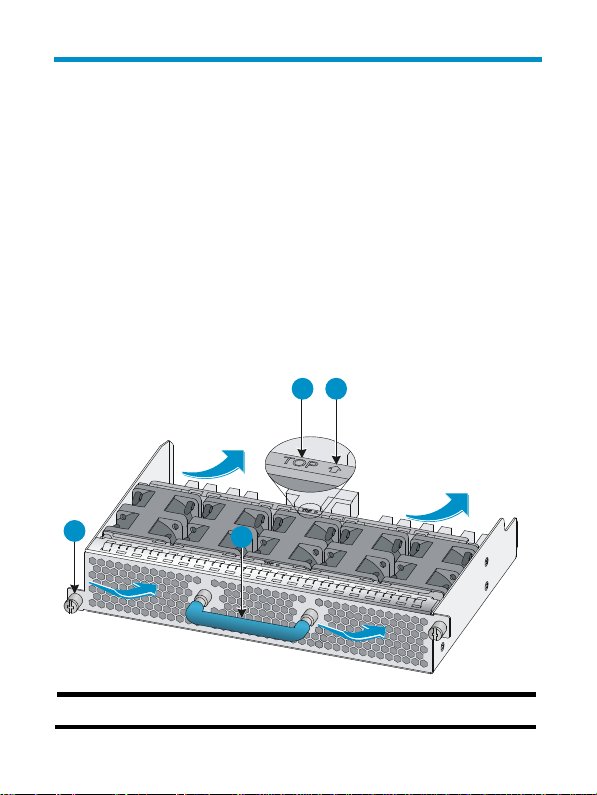
Figure 1 Fan tray view
3 4
1
(1) Captive screw
2
1
Page 5

(2) Handle (The handle is in blue, indicating that the fan tray blows
cool air into the switch from the power side to the port side.)
(3) This side up sign (4) Air flow sign
The switch provides a LED on the power side panel for each fan tray to
indicate the fan tray operating status. When the switch is running, the
LED can have the following states:
• Green—The fan tray is operating correctly.
• Red—No fan tray is installed or the fan tray is faulty.
Back-to-front airflow fan tray specifications
Table 1 Back-to-front airflow fan tray specifications
Item Specification
Number of fans
Air flow direction From the switch power side to the port side
Max fan speed 22100 revolutions per minute (R.P.M.)
Max air volume 105 cubic foot per minute (CFM)
Max power
consumption
Min power
consumption
Voltage 12 V
Five 40 × 40 × 56 mm (1.57 × 1.57 × 2.20
in) fans
130 W
18 W
2
Page 6

Front-to-back airflow fan tray
Introduction
The HP FlexFabric 7904 front (port side) to back (power side) airflow
Fan Tray (JG684A) provides powerful cooling and heat dissipation for
the switch. It blows exhaust air out of the switch from the port side to the
power side. The fan tray has five fans and features small size, fast heat
dissipation, and hot swapping. It can automatically adjust the fan speed
based on the switch temperature.
Figure 2 Front-to-back airflow fan tray view
(1) Captive screw
(2) Handle (The handle is in red, indicating that the fan tray blows
exhaust air out of the switch from the port side to the power side.)
3
Page 7

(3) Air flow sign (4) This side up sign
The switch provides a LED on the power side panel for each fan tray to
indicate the operating status of the fan tray. When the switch is running,
the LED can have the following states:
• Green—The fan tray is operating correctly.
• Red—No fan tray is installed or the fan tray is faulty.
Front-to-back airflow fan tray specifications
Table 2 Front-to-back airflow fan tray specifications
Item Specification
Number of fans
Air flow direction From the switch port side to the power side
Max fan speed 22100 revolutions per minute (R.P.M.)
Max air volume 105 cubic foot per minute (CFM)
Max power
consumption
Min power
consumption
Voltage 12 V
Five 40 × 40 × 56 mm (1.57 × 1.57 × 2.20
in) fans
130 W
18 W
4
Page 8

Installing and replacing a fan tray
IMPORTANT:
Before you install a fan tray,
• Make sure the air flow direction of the fan tray is as required.
• Make sure you install two fan trays of the same model for the
switch.
The installation and removal procedures for the back-to-front airflow fan
tray and front-to-back airflow fan tray are similar.
Installing a fan tray
1. Wear an ESD wrist strap, and make sure it makes good skin
contact and is correctly grounded.
2. Use a Phillips screwdriver to loosen the captive screws on the
blank panel of the fan tray slot. See callout 1 in Figure 3.
3. Thread a flat-hea
panel and pull out the blank panel gently. See callout 2 in Figure
3.
Keep the
4. Unpack the fan tray.
5. Holding the fan tray with both hands with the upside (marked with
a "TOP" sign) up, gently push the fan tray into the slot along the
guide rails until the fan tray completely seats into the slot. See
callout 3 in Figure 3.
d screwdriver through the handle on the blank
removed blank panel for future use.
5
Page 9

6. Use a Phillips screwdriver to tighten the captive screws on the fan
tray to make sure the fan tray is fully seated in the slot.
7. Verify the fan tray installation by examining the fan tray LED on the
power side.
{ If the LED is steady green, the installation is correct.
{ If the LED is in red, the fan tray is faulty. Remove and re-install
the fan tray. If the problem persists, contact HP Support.
6
Page 10

Figure 3 Installing a fan tray
1
2
3
NOTE:
• If you insert the fan tray with the upside down, you cannot
completely insert it into the slot. If this happens, pull the fan tray
out and then insert it again with the upside up.
• If the captive screws cannot be attached tightly, check for the
installation of the fan tray.
7
Page 11

Replacing a fan tray
CAUTION:
• When you replace a fan tray from a running switch, be cautious
of electricity hazards, and do not touch the rotating fan to avoid
bodily injury.
• If a fan tray fails, finish replacing the fan tray within 5 minutes. If
both fan trays fail, finish replacing the fan trays within 3 minutes
to avoid switch damage.
IMPORTANT:
Make sure the new fan tray is the same model as the one to be
replaced.
To replace a fan tray:
1. Prepare an antistatic bag for the removed fan tray.
2. Wear an ESD wrist strap, and make sure it makes good skin
contact and is correctly grounded.
3. Use a screwdriver to loosen the captive screws of the fan tray. See
callout 1 in Figure 4.
4. Holding th
chassis. See callout 2 in Figure 4.
5. Put the removed
6. Install a new fan tray. For more information, see "Installing a fan
tray."
e handle of the fan tray, pull the fan tray out of the
fan tray into the antistatic bag.
8
Page 12

Figure 4 Removing a fan tray
9
Page 13

Support and other resources
Contacting HP
For worldwide technical support information, see the HP support
website:
http://www.hp.com/support
Before contacting HP, collect the following information:
• Product model names and numbers
• Technical support registration number (if applicable)
• Product serial numbers
• Error messages
• Operating system type and revision level
• Detailed questions
Subscription service
HP recommends that you register your product at the Subscriber's
Choice for Business website:
http://www.hp.com/go/wwalerts
After registering, you will receive email notification of product
enhancements, new driver versions, firmware updates, and other
product resources.
10
 Loading...