

Page 1

installation and user’s guide
hp visualization center sv6
Manufacturing Part Number: A6062-90005
Edition: E0302
Printed in U.S.A
Page 2

legal notices
The information in this document is subject to change without notice.
Hewlett-Packard makes no warranty of any kind with regard to this manual,
including, but not limited to, the implied warranties of merchantability and
fitness for a particular purpose.
errors contained herein or direct, indirect, special, incidental or
consequential damages in connection with the furnishing, performance,
or use of this material.
restricted rights legends. Use, duplication or disclosure by the U.S.
Government is subject to restrictions as set forth in subparagraph (c) (1) (ii) of
the Rights in Technical Data and Computer Software clause at DFARS
252.227-7013 for DOD agencies, and subparagraphs (c) (1) and (c) (2) of the
Commercial Computer Software Restricted Rights clause at FAR 52.227-19 for
other agencies.
HEWLETT-PACKARD COMPANY
3000 Hanover Street
Palo Alto, California 94304 U.S.A.
Use of this manual, CD(s) and flexible disk(s) or tape cartridge(s) supplied for
this product is restricted to this product only. Additional copies of the programs
may be made for security and back-up purposes only. Resale of the programs in
their present form or with alterations, is expressly prohibited.
copyright notices.
©copyright 1983-2001 Hewlett-Packard Company, all rights reserved.
Hewlett-Packard shall not be held liable for
Reproduction, adaptation, or translation of this document without prior written
permission is prohibited, except as allowed under the copyright laws.
©copyright 1979, 1980, 1983, 1985-93 Regents of the University of California
This software is based in part on the Fourth Berkeley Software Distribution
under license from the Regents of the University of California.
©copyright 1980, 1984, 1986 Novell, Inc.
©copyright 1986-1992 Sun Microsystems, Inc.
©copyright 1985-86, 1988 Massachusetts Institute of Technology.
©copyright 1989-93 The Open Software Foundation, Inc.
©copyright 1986 Digital Equipment Corporation.
©copyright 1990 Motorola, Inc.
©copyright 1990, 1991, 1992 Cornell University
©copyright 1989-1991 The University of Maryland
©copyright 1988 Carnegie Mellon University
Page 3

trademark notices. UNIX is a registered trademark in the United States and
other countries, licensed exclusively through X/Open Company Limited.
X Window System is a trademark of the Massachusetts Institute of Technology.
printing history
The manual printing date and part number indicate its current edition. The
printing date will change when a new edition is printed. Minor changes may be
made at reprint without changing the printing date. The manual part number
will change when extensive changes are made.
Manual updates may be issued between editions to correct errors or document
product changes. To ensure that you receive the updated or new editions, you
should subscribe to the appropriate product support service. See your HP sales
representative for details.
First Edition: March 2002
Printing Division:
Hewlett-Packard Co.
Technical Computer Division
3404 E. Harmony Rd.
Fort Collins, CO 80525
hp product warranty statement
NOTE This warranty statement supersedes any and all previous HP-UX
workstation warranty statements for the Hewlett-Packard workstations
specified herein. The Parts-Only Base Warranty is offered only in the
U.S.; for country-specific warranties, contact your HP Country Sales
Representative. The information contained in this document is subject to
change without notice. For warranty information on the other
components of the hp visualization center sv6 system, see the warranty
documentation that accompanies those components.
Page 4

HP PRODUCT: DURATION OF WARRANTY:
hp workstations j6000, j6700 and b2600 1 Year
1. HP warrants HP hardware, accessories and supplies against defects in
materials and workmanship for the period specified above. If HP receives
notice of such defects during the warranty period, HP will, at its option,
either repair or replace products which prove to be defective. Replacement
products may be either new or like-new.
2. HP warrants that HP software will not fail to execute its programming
instructions, for the period specified above, due to defects in material and
workmanship when properly installed and used. If HP receives notice of
such defects during the warranty period, HP will replace the software
medium which does not execute its programming instructions due to such
defects.
3. HP doesnotwarrant that the operation of HP products will be uninterrupted
or error free. If HP is unable, within a reasonable time, to repair or replace
any product to a condition as warranted, the customer will be entitled to a
refund of the purchase price upon prompt return of the product.
4. HP products may contain remanufactured parts equivalent to new in
performance or may have been subject to incidental use.
5. The warranty period begins on the date of delivery or on the date of
installation if installed by HP. If customer schedules installation or causes
installation by HP to be delayed more than 30 days after delivery, warranty
begins on the 31st day from delivery.
6. Warranty does not apply to defects resulting from (a) improper or inadequate
maintenance or calibration, (b) software, interfacing, parts or supplies not
supplied by HP, (c) unauthorized modification or misuse, (d) operation
outside of the published environmental specifications for the product, or (e)
improper site preparation or maintenance.
7. TO THE EXTENT ALLOWED BY LOCAL LAW, THE ABOVE
WARRANTIES ARE EXCLUSIVE AND NO OTHER WARRANTY OR
CONDITION, WHETHER WRITTEN OR ORAL, IS EXPRESSED OR
IMPLIED AND HP SPECIFICALLY DISCLAIMS ANY IMPLIED
WARRANTIES OR CONDITIONS OF MERCHANTABILITY,
SATISFACTORY QUALITY, AND FITNESS FOR A PARTICULAR
PURPOSE.
8. HP will be liable for damage to tangible property per incident up to the
greater of $300,000 or the actual amount paid for the product that is the
subject of the claim, and for damages for bodily injury or death, to the extent
that all such damages are determined by a court of competent jurisdiction to
have been directly caused by a defective HP product.
4
Page 5

9. TO THE EXTENT ALLOWED BY LOCAL LAW, THE REMEDIES IN THIS
WARRANTY STATEMENT ARE CUSTOMERS’ SOLE AND EXCLUSIVE
REMEDIES. EXCEPT AS INDICATED ABOVE, IN NO EVENT WILL HP
OR ITS SUPPLIERS BE LIABLE FOR LOSS OF DATA OR FOR DIRECT,
SPECIAL, INCIDENTAL, CONSEQUENTIAL (INCLUDING LOST
PROFIT OR DATA), OR OTHER DAMAGE, WHETHER BASED IN
CONTRACT, TORT, OR OTHERWISE.
FOR CONSUMER TRANSACTIONS IN AUSTRALIA AND NEW
ZEALAND: THE WARRANTY TERMS CONTAINED IN THIS
STATEMENT, EXCEPT TO THE EXTENT LAWFULLY PERMITTED, DO
NOT EXCLUDE, RESTRICT OR MODIFY AND ARE IN ADDITION TO
THE MANDATORY STATUTORY RIGHTS APPLICABLE TO THE SALE
OF THIS PRODUCT TO YOU.
for additional information
There are several sources of hp visualization center sv6 documentation
that were either shipped with your system or are available at various
Web sites:
• hp visualization center sv6 Site Preparation Guide (HP Part No.
A6062-90006)
• hp visualization center sv6 Troubleshooting Guide (available on
http://www.hp.com/go/workstationsupport Web site)
• hp visualization center sv6 Recovery Instructions CD Booklet (HP
Part No. A6062-90010 included in the Recovery CD jewel case)
• hp ProCurve Switch User’s Guide
— hp 10/100 ProCurve (J4813A)
— hp ProCurve Switch 4108gl (J4865A)
• Digi EtherLite-32 terminal Server documentation (CD instructions
or http://www.digi.com).
For further information, refer to these Web pages:
• HP immersive environments page:
http://www.hp.com/go/immersive/index.html
5
Page 6

• User Guides for hp workstations:
http://www.hp.com/go/workstationsupport/documentation/manuals
/user_guides
NOTE Every effort was made to make sure this information was complete at the
time it was printed. However, additional information and
troubleshooting tips may have become available after this guide was
printed. For the very latest information, please visit the
http://www.hp.com/go/workstationsupport Web site.
viewing documentation on the recovery CD
All hp visualization center sv6 documentation is also included on the hp
visualization center sv6 Installation/Recovery CD that is shipped with
your system.To view these documents:
1. Mount the CD by executing:
mount /dev/dsk/c0t0d0 /cdrom
2. Make sure the directory for your Adobe Acrobat Reader is in your
PATH:
export PATH=$PATH:/opt/Acrobat4/bin
3. The following hp visualization center sv6 documentation is available:
sv6SitePrepGuide.pdf
sv6InstUsersGuide.pdf
sv6TroubleShootGuide.pdf
4. To view the files:
acroread /cdrom/<filename.pdf>
6
Page 7

Contents
1. safety and support information
how to obtain support for your sv6 system. . . . . . . . . . . . . . . . . . . . . . . .12
safety warnings . . . . . . . . . . . . . . . . . . . . . . . . . . . . . . . . . . . . . . . . . . . . .14
rack stability. . . . . . . . . . . . . . . . . . . . . . . . . . . . . . . . . . . . . . . . . . . . . .14
power distribution units (PDUs) . . . . . . . . . . . . . . . . . . . . . . . . . . . . . .15
metallic particulate contamination. . . . . . . . . . . . . . . . . . . . . . . . . . . .17
2. installation and user information
document purpose . . . . . . . . . . . . . . . . . . . . . . . . . . . . . . . . . . . . . . . . . . .20
section descriptions . . . . . . . . . . . . . . . . . . . . . . . . . . . . . . . . . . . . . . . .20
product overview . . . . . . . . . . . . . . . . . . . . . . . . . . . . . . . . . . . . . . . . . . . .22
hp visualization center sv6 components . . . . . . . . . . . . . . . . . . . . . . . .24
hp visualization center sv6 architecture. . . . . . . . . . . . . . . . . . . . . . . .28
supported configurations . . . . . . . . . . . . . . . . . . . . . . . . . . . . . . . . . . . .32
software configurations . . . . . . . . . . . . . . . . . . . . . . . . . . . . . . . . . . . . .34
installation process . . . . . . . . . . . . . . . . . . . . . . . . . . . . . . . . . . . . . . . . . .36
assessment . . . . . . . . . . . . . . . . . . . . . . . . . . . . . . . . . . . . . . . . . . . . . . .36
preparation for wide field displays . . . . . . . . . . . . . . . . . . . . . . . . . . . .37
hp visualization center sv6 installation . . . . . . . . . . . . . . . . . . . . . . . .38
software setup specifications. . . . . . . . . . . . . . . . . . . . . . . . . . . . . . . . . . .46
updating software . . . . . . . . . . . . . . . . . . . . . . . . . . . . . . . . . . . . . . . . . . .47
maintain current graphics patches . . . . . . . . . . . . . . . . . . . . . . . . . . . .47
Installation Steps . . . . . . . . . . . . . . . . . . . . . . . . . . . . . . . . . . . . . . . . . .48
uninstallation steps . . . . . . . . . . . . . . . . . . . . . . . . . . . . . . . . . . . . . . . .49
installing to all sv6 systems using HP Software Distributor . . . . . . .50
step 1: preparation . . . . . . . . . . . . . . . . . . . . . . . . . . . . . . . . . . . . . . . . .51
step 2: copy and register locally. . . . . . . . . . . . . . . . . . . . . . . . . . . . . . .52
step3: install . . . . . . . . . . . . . . . . . . . . . . . . . . . . . . . . . . . . . . . . . . . . . .53
step 4: verification . . . . . . . . . . . . . . . . . . . . . . . . . . . . . . . . . . . . . . . . .54
7
Page 8

Contents
advanced setup for multiple display channels . . . . . . . . . . . . . . . . . . . . 55
additional X server . . . . . . . . . . . . . . . . . . . . . . . . . . . . . . . . . . . . . . . . 55
configuring offset overlap . . . . . . . . . . . . . . . . . . . . . . . . . . . . . . . . . . 57
backdrops. . . . . . . . . . . . . . . . . . . . . . . . . . . . . . . . . . . . . . . . . . . . . . . . 60
usage . . . . . . . . . . . . . . . . . . . . . . . . . . . . . . . . . . . . . . . . . . . . . . . . . . . . 62
changing resolution. . . . . . . . . . . . . . . . . . . . . . . . . . . . . . . . . . . . . . . . 63
how to use hp visualization center sv6 tools. . . . . . . . . . . . . . . . . . . . . . 65
sv6 diagnostics . . . . . . . . . . . . . . . . . . . . . . . . . . . . . . . . . . . . . . . . . . . 71
stereoscopic viewing . . . . . . . . . . . . . . . . . . . . . . . . . . . . . . . . . . . . . . . . 74
active stereo overview. . . . . . . . . . . . . . . . . . . . . . . . . . . . . . . . . . . . . . 74
passive stereo overview. . . . . . . . . . . . . . . . . . . . . . . . . . . . . . . . . . . . . 74
stereo hardware installation . . . . . . . . . . . . . . . . . . . . . . . . . . . . . . . . . . 75
changing to stereo monitor mode . . . . . . . . . . . . . . . . . . . . . . . . . . . . 76
optimization . . . . . . . . . . . . . . . . . . . . . . . . . . . . . . . . . . . . . . . . . . . . . . . 78
pass through mode . . . . . . . . . . . . . . . . . . . . . . . . . . . . . . . . . . . . . . . . 82
gamma value . . . . . . . . . . . . . . . . . . . . . . . . . . . . . . . . . . . . . . . . . . . . 84
HPOGL_PUSH _ENVIRONMENT . . . . . . . . . . . . . . . . . . . . . . . . . . . 84
3. file configuration
4. projector calibration targets
how to use projector calibration targets . . . . . . . . . . . . . . . . . . . . . . . . . 92
A. hp scalable visualization digital compositor
compositor cards. . . . . . . . . . . . . . . . . . . . . . . . . . . . . . . . . . . . . . . . . . . . 98
compositor parts list . . . . . . . . . . . . . . . . . . . . . . . . . . . . . . . . . . . . . . 101
compositor configurations. . . . . . . . . . . . . . . . . . . . . . . . . . . . . . . . . . 102
sv6 compositor frame delay . . . . . . . . . . . . . . . . . . . . . . . . . . . . . . . . . . 103
compositor self-test sequence. . . . . . . . . . . . . . . . . . . . . . . . . . . . . . . . . 105
8
Page 9

Contents
introduction . . . . . . . . . . . . . . . . . . . . . . . . . . . . . . . . . . . . . . . . . . . . .105
interface . . . . . . . . . . . . . . . . . . . . . . . . . . . . . . . . . . . . . . . . . . . . . . . .105
procedure . . . . . . . . . . . . . . . . . . . . . . . . . . . . . . . . . . . . . . . . . . . . . . .105
testing output or input cards. . . . . . . . . . . . . . . . . . . . . . . . . . . . . . . .106
testing controller cards . . . . . . . . . . . . . . . . . . . . . . . . . . . . . . . . . . . .106
LED indicators . . . . . . . . . . . . . . . . . . . . . . . . . . . . . . . . . . . . . . . . . . .106
B. hp mini-sv6 configuration
mini-sv6 configuration. . . . . . . . . . . . . . . . . . . . . . . . . . . . . . . . . . . . . . .108
C. regulatory information
FCC radio frequency interference statement
(USA only) . . . . . . . . . . . . . . . . . . . . . . . . . . . . . . . . . . . . . . . . . . . . . . . .113
glossary
9
Page 10

Contents
10
Page 11

1 safety and support information
Proper site preparation and maintenance are vital to the reliability of
any computer hardware component. In order for HP to provide you with
quality service, please ensure that the proper computer room conditions
are maintained. This allows HP to provide support services in
Chapter 1 11
Page 12

safety and support information
how to obtain support for your sv6 system
accordance with your Customer Support Services Agreement.
For your protection, HP products are tested for conformance to various
national and international regulations and standards. The scope of this
regulatory testing includes electrical and mechanical safety,
electromagnetic emissions,electromagnetic immunity, ESD (electrostatic
discharge), acoustics, and hazardous materials. Where required,
certifications are obtained from third-party test agencies. Certification
marks appear on the product label. In addition, various regulatory
bodies require information to appear in User Manuals.
how to obtain support for your sv6 system
If you know you have a hardware problem:
1. Retrieve the model number and serial number of the failed
hardware.
2. Call the HP Customer Care Center for your region, country or
province. These numbers can be found at: http://www.hp.com under
Technical Support. For example, use 1-800-633-3600 for North
America.
3. When you reach the appropriate Customer Care Center, you will
have several options. Press 1 for Hardware Support.
4. For warranty verification and to help track your call, you will be
asked to provide the model number and serial number for the failed
hardware (see Step 1 above).
5. If the HP Call Agent cannot resolve your problem, then tell the Call
Agent that the failed or problematic hardware is part of an hp sv6
scalable visualization system. Your call will be re-directed to an hp
sv6 expert who is trained to provide solution-level assistance.
If you have a software problem or don't know the source of the problem:
1. Retrieve the software “handle” (a unique support identifier) that was
provided with the hp sv6 system at installation.
Chapter 112
Page 13

safety and support information
how to obtain support for your sv6 system
2. Call the HP Customer Care Center for your region, country or
province. These numbers can be found at: http://www.hp.com under
Technical Support. For example, use 1-800-633-3600 for North
America.
3. When you reach the appropriate Customer Care Center, you will
have several options. Press 2 for Software Support.
4. For call tracking purposes, you will be asked to provide the HP Call
Agent with your software “handle” (see Step 1 above).
5. Tell the Call Agent that you have an hp sv6 scalable visualization
system. The Call Agent will re-direct your call to an hp sv6 expert
who is trained to provide assistance with your system
Chapter 1 13
Page 14

safety and support information
safety warnings
safety warnings
WARNING An hp visualization sv6 product rack can weigh 1500 lbs. (681 kg)
when fully loaded with hardware components. Heed all of the
conditions in the WARNING statement under the RACK
STABILITY subsection below when moving and servicing an HP
product rack and its rack-mounted hardware components.
WARNING Your hp visualization center sv6 product may not have been
evaluated for connection to an IT power system (an AC
distribution system having a high impedance connection to
earth according to IEC 950).
rack stability
WARNING To reduce the risk of rack instability:
• Install the heavier hardware components at the bottom of the
rack, below the center of gravity for the rack. Never install
heavier components in the top or upper portion of the rack.
• Make sure that the anti-tip plate is installed on the rack. Do
not remove the anti-tip foot from the rack.
• Always extend the anti-tip plate before extending a
rack-mounted component for servicing.
• Extend only one rack-mounted component at a time.
• Do not stand or sit on any extended component.
• Have all non-operator servicing done by qualified HP service
personnel.
Chapter 114
Page 15
safety and support information
safety warnings
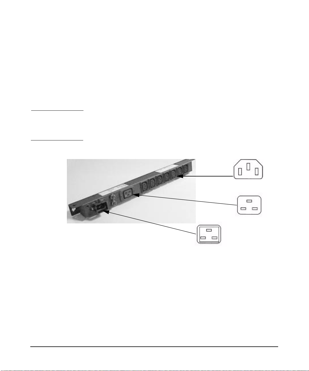
power distribution units (PDUs)
A Power Distribution Unit (PDU) is equipment located in or near a
computer room which breaks down electric power from a high-voltage
source to appropriate levels of distribution to the central processing unit
and peripheral devices of a computer system. Figure 1-1 shows an
example PDU that is used with the HP product racks. This example is
the HP E7674A 16 Amp 100-240VAC PDU (part number A5137AZ).
CAUTION Some components have been designed to be used with specific electrical
accessories such as PDUs. The use of any accessory other than those
specified is neither recommended nor supported.
Figure 1-1 A Sample Power Distribution Unit (PDU)
Qty=7
IEC320-C13
IEC320-C19
Modular PDU
C20 Inlet
Chapter 1 15
Page 16
safety and support information
safety warnings
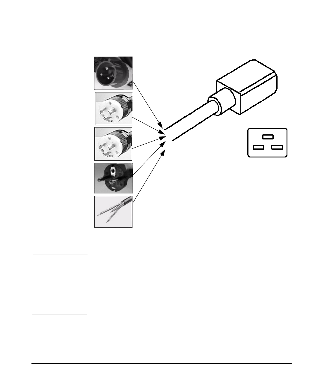
Figure 1-2 Cable and Plugs Between the PDU and the Wall Receptacle
IEC309
L6-20P
L6-30P
IEC-320-C19
CEE7/7
Unterminated
PDU leakage current
WARNING Due to the number of components that can be installed on one
Power Distribution Unit (PDU), there may be a risk of high
leakage current (>3.5mA). Reliable ground circuit continuity is
vital for safe operation of such components. To reduce the risk of
electric shock, connect each component to a grounded outlet
only. Never operate any component with its ground pin
disconnected from the socket of a grounded outlet.
Chapter 116
Page 17

safety and support information
safety warnings
PDU power limitations
To reduce the risk of overload, do not exceed the rated load of any single
PDU. In addition, do not load a single NEMA 5-15 (see Fig. 1-3)
receptacle with more than 15 Amperes and any single IEC 320-1/C13
receptacle with more than 10 Amperes. In general, make sure that the
power source circuits are able to safely provide the current that will be
required by all components drawing power from them. This document
assumes that 220V and 240V cables are used.
NEMA 5-15 Receptacle
Do not load this
connector with
more than 15 Amps
metallic particulate contamination
Metallic particulates can be especially harmful around electronic
equipment. This type of contamination may enter the data center
environment from a variety of sources, including, but not limited to,
raised floor tiles, worn air conditioning parts, heating ducts, rotor
brushes in vacuum cleaners or printer component wear. Because metallic
particulates conduct electricity, they have an increased potential for
creating short circuits in electronic equipment. This problem is
exaggerated by the increasingly dense circuitry of electronic equipment.
Over time, very fine whiskers of pure metal can form on electroplated
zinc, cadmium, or tin surfaces. If these whiskers are disturbed, they may
break off and become airborne, possibly causing failures or operational
interruptions. Forover 50 years, the electronics industry has been aware
of the relatively rare, but possible, threat posed by metallic particulate
contamination. During recent years, a growing concern has developed in
computer rooms where these conductive contaminants are formed on the
bottom of some raised floor tiles.
Chapter 1 17
Page 18

safety and support information
safety warnings
Although this problem is relatively rare, it may be an issue within your
computer room. Since metallic contamination can cause permanent or
intermittent failures on your electronic equipment, Hewlett-Packard
strongly recommends that your site be evaluated for metallic particulate
contamination before installation of electronic equipment.
Chapter 118
Page 19

2 installation and user information
Chapter 2 19
Page 20

installation and user information
document purpose
document purpose
The purpose of this document is to provide information on installing,
customizing and using hp visualization center sv6 systems. Because the
workstations will arrive racked, pre-cabled and pre-configured, minimal
information about hardware setup is included in this document. Sections
of this document provide steps for setting up and configuring systems.
There are also sections that provide instructions on how to use hp
visualization center sv6-specific tools. Refer to the Glossary for
definitions of terms used in this document.
See the following documents for additional information:
• hp visualization center sv6 Site Prep Guide for cooling, space and
• hp visualization center sv6 Troubleshooting Guide - see
power requirements, etc.
http://www.hp.com/go/workstationsupportfor tips on how to resolve
problems you may encounter during the initial setup and
customization.
• hp disk system ds2100 - see
http://www.hp.com/products1/storage/disk_arrays/disksystems/ds
2100/supplies/index.html
• /etc/X11/X0screens for X server configuration details or
/usr/lib/X11/Xserver/misc/slsd/templates/ for hp
visualization center sv6 X0screens templates.
• /usr/lib/X11/Xserver/info/screens/hp for non- hp
visualization center sv6 X server configuration details.
•/opt/graphics/OpenGL/sv/doc/README.* for details about hp
visualization center sv6 tools.
section descriptions
• Product Overview - Provides a general hardware and software
architecture overview.
• Installation - Steps that the hp visualization center sv6 installer
will help you accomplish.
Chapter 220
Page 21

installation and user information
document purpose
• Software Set-Up Specifications - Reference for the software that
was pre-loaded on your system.
• Updating Software - Explains how and when to do software and
firmware updates. Keeping your graphics patches updated is
essential for taking full advantage of this new technology.
• Advanced Set-Up for Multiple Channels - Gives an overview of
how to use multiple hp visualization center sv6 clusters to output
across multiple display devices. This is a reference for anyone who
wants to upgrade to multiple channels.
• Usage - General instructions on how to do typical tasks. Although
you can run applications on the hp visualization center sv6 the same
way you would on any HP-UX workstation, there are a few hp
visualization center sv6-specific tasks that can be performed.
• How To Use hp visualization center sv6 Tools - Reference for hp
visualization center sv6-specific tools.
• Stereoscopic Viewing - Describes both active and passive stereo
options and how to enable them.
• Optimization - Suggests methods for optimizing both rendering
performance and image quality for your application or data sets.
Chapter 2 21
Page 22

installation and user information
product overview
product overview
The hp visualization center sv6 solution is a system developed to meet
your visualization performance and image quality needs. The key
attributes that make this system unique from existing scalable solutions
include:
• scalable rendering performance, image quality and resolution,
• resources can be dynamically switched between performance and
• use of standard SPU and graphics components.
The hp visualization center sv6 provides the following benefits:
• Applications that currently run on standalone hp visualization
• The use of standard components with the ability to add, re-deploy or
image quality,
center systems today can also run unmodified on hp visualization
center sv6 systems and immediately take advantage of the scaling
and image quality improvements.
upgrade these components provides significant investment
protection.
• The individual workstations of the scalable system can be used as
computational resources when not being used for visualization.
Chapter 222
Page 23
installation and user information
product overview
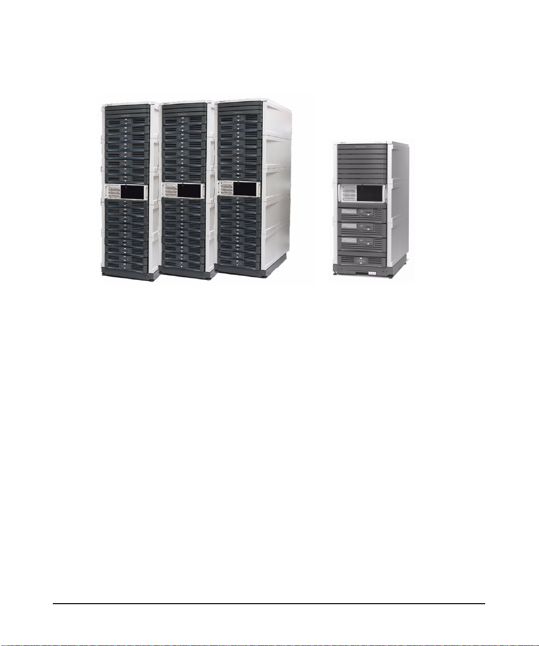
Figure 2-1 hp visualization centers sv6 (j6700) and mini-sv6 (b2600)
The hp visualization center sv6 is:
• A scalable solution for OpenGL display list-based applications that
provides geometry acceleration of aliased rendering that is greater
than stand-alone hp workstation performance.
• A solution that offers increased visual quality via anti-aliasing at
stand-alone hp workstation performance rates, or better.
• A solution that is scalable in any combination of performance, visual
quality or screen resolution; limited only by supported
configurations.
• A solution that is transparent to the application.
• A solution that involves multiple standard graphics pipelines
rendering a common model with a single view frustum.
• An OpenGL HP-UX 11.0 based solution only.
hp visualization center sv6 employs a parallel rendering architecture. It
uses dedicated accelerators for rendering portions of a given screen. The
resulting renderings (called “screen rectangles”) are synchronized and
displayed as a single image through additional hardware.
hp visualization center sv6 is based on a client/server architecture called
Distributed Single LogicalScreen (SLS/d). This technology transparently
manages multiple clients that render portions of a given screen. Each hp
Chapter 2 23
Page 24

installation and user information
product overview
visualization center hp visualization center sv6 cluster is made up of one
2D master node and a supported number of 3D slave nodes. The 2D node
is responsible for rendering the GUI and X11 rendering primitives. The
3D slave nodes, also called “pipes,” are responsible for rendering all or
some part of the 3D scene. The video output from each node is then
combined, or composited, to a single monitor.
To obtain multiple channels of output, multiple clusters can be used. A
“channel” refers to one output device, typically a monitor. This allows for
more screen “real estate” (two or three displays) by using multiple hp
visualization center sv6 clusters.
hp visualization center sv6 components
• A cluster of racked, graphics-enabled hp workstations j6000
• Scalable Visualization Digital Compositor (A6061A).
• Private, High-Speed Gigabit Network - hp ProCurve switch 4108gl
(A5990A), j6700 (A7278B) or b2600 (A6070A).
(J41865A).
• hp ProCurve 10/100 Base-T 2524 switch (J4813A) for LAN
connection.
• Digi EtherLite-32 Terminal Server (DGZ1469C).
• EasySetup HP-UX 11.0 operating system (B5532A).
• Scalable Visualization-enabled software (X Server, OpenGL,
3DCommon, etc.).
• Customized Configuration Files (see Chapter 3).
Figure 2-2 is an example of a 16-pipe system that shows the hardware
components.
Chapter 224
Page 25
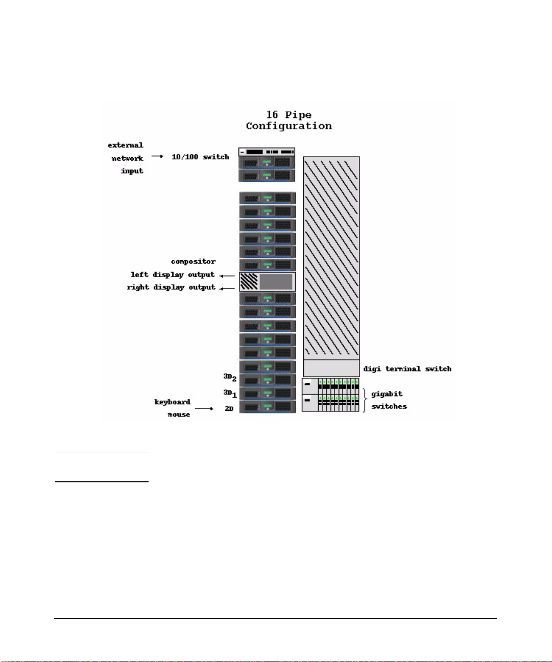
Figure 2-2 16-pipe system configuration
installation and user information
product overview
NOTE Arrangement of the hardware in the racks may vary.
The 2D master system controls the rendering that happens on the 3D
pipes. The output of each pipe is then fed into hardware called the
Digital Compositor. The Compositor combines the inputs into a single
output stream to the display. A local high-speed Gigabit Ethernet switch
(hp ProCurve Switch) which connects the systems.
The Digi EtherLite-32 terminal server (D GZ1469C) is a low-cost option
for consolidating consoles. Each Digi switch provides remote access for
up to 32 systems. The Digi EtherLite driver runs on the master system.
Chapter 2 25
Page 26
installation and user information
product overview
This driver communicates with the EtherLite-32 and makes the Digi
switch’s serial connections appear as though they were direct serial
connections to the master system. Thus, the master node communicates
with the slave node via a serial port communications program, such as cu
on HP-UX or the dinc program supplied with the Digi switch.
Examples for accessing save node #2:
cu -l/dev/ttyn01 -s 9600
/usr/local/bin/dinc /dev/digi/sv2
The Digi EtherLite-32 has its own IP address and is connected to the
10/100 hub. RJ45 ports are connected to serial port 1 of each slave node
via an RS-232 adapter.
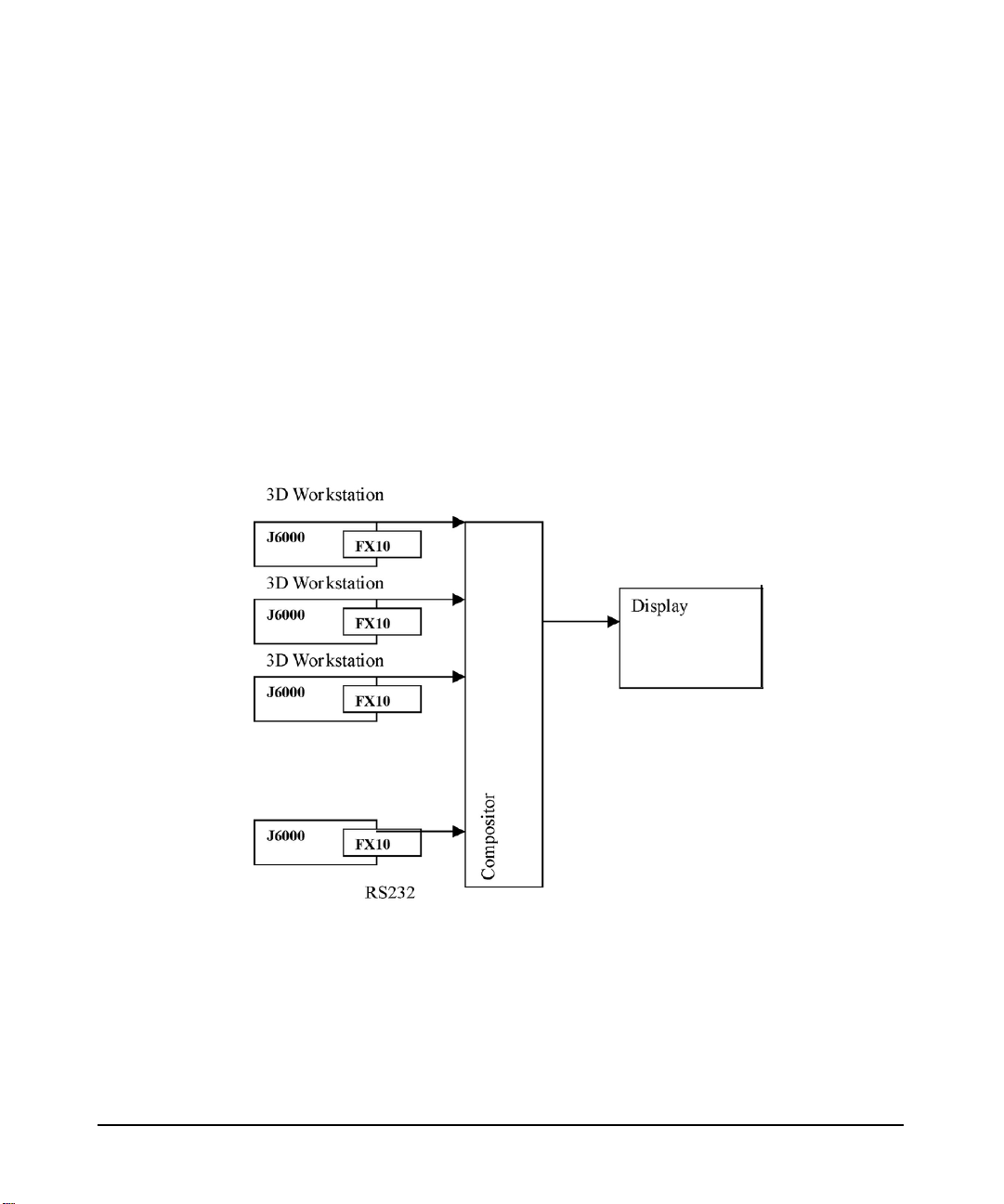
Figure 2-3 Single Display Channel
Each workstation has one graphics card. The master workstation does
2D rendering and the rest of the workstations do 3D rendering. Each hp
visualization center sv6 cluster outputs to a single display. Each graphics
device is connected to the compositor through a digital video connection.
Each workstation is connected to the hp ProCurve 10/100 BaseT switch
(J4813A) which provides a connection to the site’s LAN.
Chapter 226
Page 27
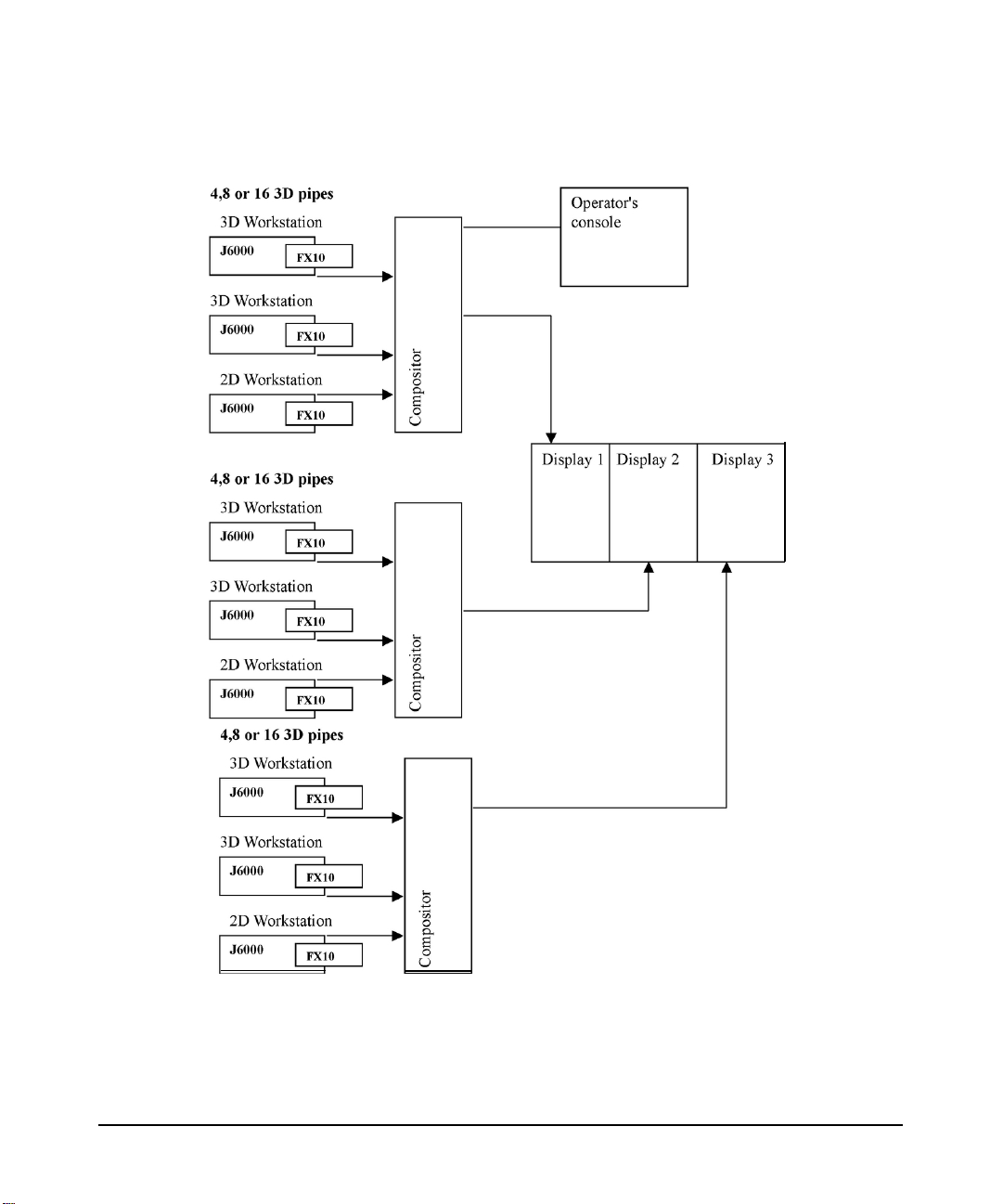
Figure 2-4 Multiple Display Channels
installation and user information
product overview
For multiple displays (up to three displays) additional hp visualization
center sv6 clusters can be added to increase screen real-estate. “Screen
real estate” describes the expanded workspace created by spreading one
continuous screen across several display devices.
Chapter 2 27
Page 28
installation and user information
product overview
hp visualization center sv6 architecture
This section discusses a general overview of how the hardware is used by
the hp visualization center sv6 architecture, using a 16-pipe system as
an example:
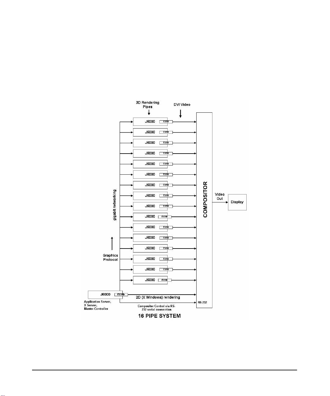
Figure 2-5 16-pipe System Architecture
The 16-pipe system contains 16 hp workstations j6000 (A5990A) or j6700
(A7278A) which perform the 3D rendering. Each of these machines
contain the hp fx10 Graphics Accelerator Card (A1299B). Each fx10 DVI
(Digital Video Interface) output connects to an input of the digital
compositor (A6061A).
Chapter 228
Page 29
installation and user information
product overview
The 17th hp workstation fulfills three roles:
1. Application Server: This is the machine on which the application
runs. Graphics protocol based on OpenGL is sent to the 16 3D
systems via high-speed Gigabit networking.
2. Xserver: In addition to running the application, this machine also
renders the 2D X window system and responds to the keyboard and
mouse.
3. Compositor Controller: This machine controls operation of the
Compositor via an RS-232 serial connection.
The Compositor processes the DVI video from each hp fx10 card and
generates the output video. The Compositor can be programmed to
process the video input signals in a number of ways.
hp visualization center sv6 operating modes
The key to understanding the hp visualization center sv6 configurations
is to understand its three operating modes - Accelerate, Accumulate and
Mixed. These modes can be changed using the
/opt/graphics/OpenGL/sv/bin/setpipes command. In the
descriptions below, a “pipe” refers to a workstation that does 3D
rendering. A “channel” is the output sent to one output device.
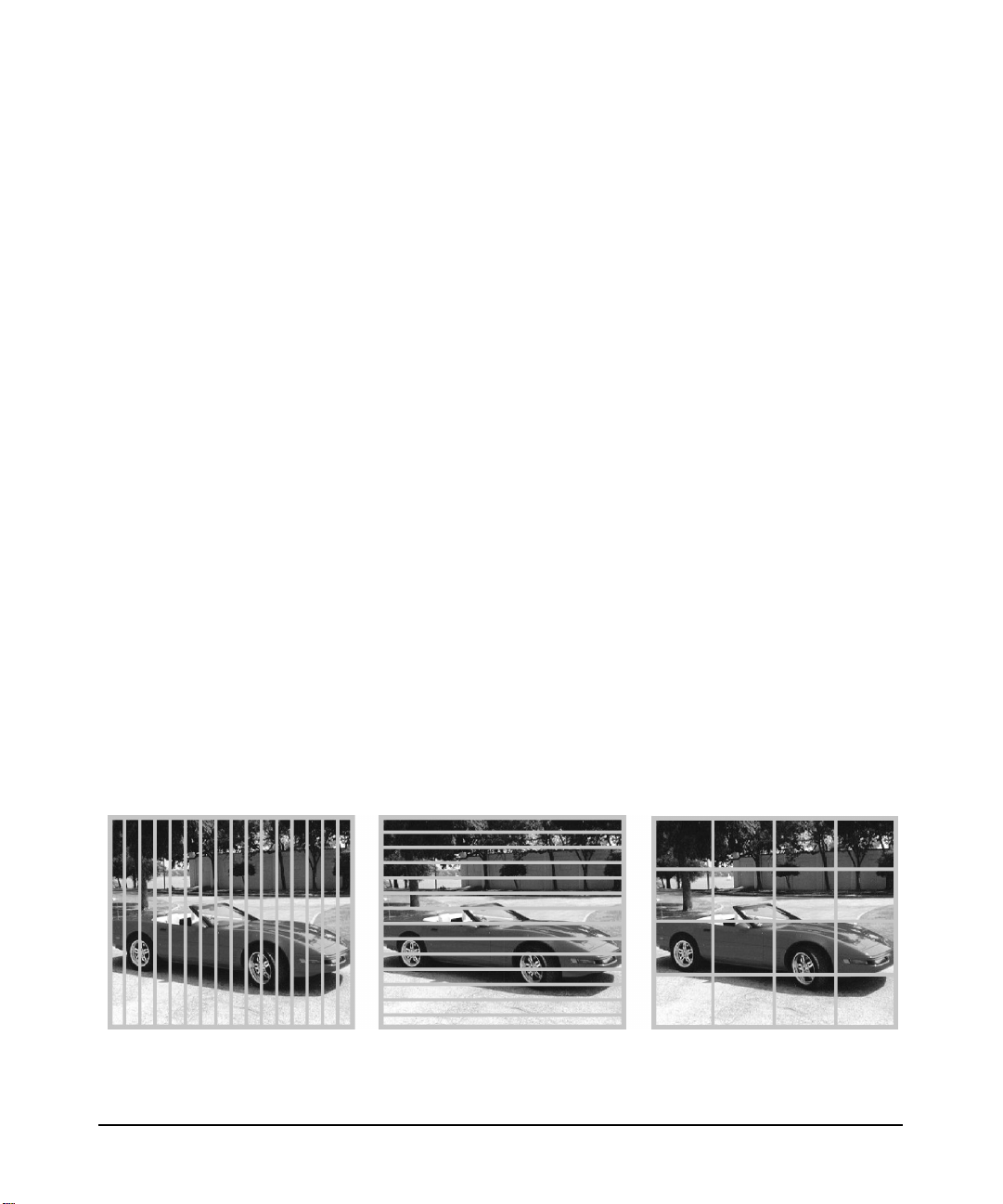
• Accelerate Mode: Enhances rendering performance
Each pipe renders a fraction of the screen, thus speeding up
performance.
Figure 2-6 Accelerate Mode - Vertical slice, Horizonal slice and Grid
Chapter 2 29
Page 30
installation and user information
product overview
NOTE Each fraction of the screen is called a “screen rectangle.”
Example: In a configuration with five workstations (one doing 2D
rendering and four doing 3D rendering), each 3D workstation would
output one of the four screen rectangle areas on the display.
You can specify how the screen is dissected. The basic options are
grid, vertical slice, horizontal slice and pane. See the
/opt/graphics/OpenGL/sv/doc/README.setpipes file for more
details.
• Accumulate Mode: Improves Image Quality
Each pipe generates the complete screen, “jittered” by sub-pixel
values. These jittered images are averaged together to achieve a
better quality image. This mode is sometimes referred to as the
anti-aliasing mode. The more workstations you add, the more
samples can be taken, and the better the resulting image quality.
Figure 2-7 Accumulate Mode
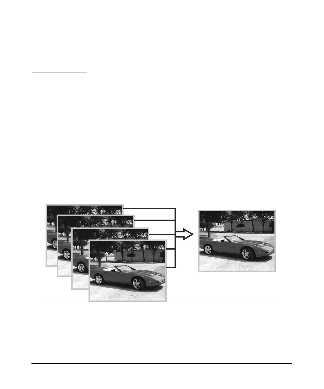
• Mixed Mode: Combination of both Accelerate and Accumulate
Modes
Each screen rectangle is generated (jittered and averaged) by the
number of samples designated. There is improved image quality
(anti-aliasing), and also improved performance (acceleration) since
each area is generated by multiple workstations.
Chapter 230
Page 31

Figure 2-8 Mixed Mode
For example, with a 16-pipe hp visualization center sv6, each of the
quadrants pictured above could be accumulated by N graphics-enabled
workstations (N is equal to the number of samples to be jittered). If N=4,
then you get four samples for accumulation on each section and since the
screen has been split into four sections, you also get improved
acceleration.
installation and user information
product overview
To increase the rendering performance, use the Accelerate Mode. To
increase image quality, use Accumulate Mode. To improve both,
experiment with Mixed Mode to achieve the desired balance of both.
Figure 2-9 shows the hardware arrangement needed to produce the
output in Figure 2-8.
Chapter 2 31
Page 32

installation and user information
product overview
Figure 2-9 Mixed Mode 16-Pipe Example
supported configurations
Each channel is driven by a set of workstations assigned to do 3D
rendering (3D pipes) plus one to do 2D rendering (2D pipe). This table
shows the hardware combinations that are supported.
Chapter 232
Page 33

Table 2-1 Hardware Configurations
Number of Display Channels
installation and user information
product overview
3D pipes
/channel
3**
4
7 **
8
16 17 workstations 34 workstations 51 workstations
** Mini-sv6 configurations have slightly lower performance because their second
master node doubles as a 3D render node using its 2D HP fx10 graphics card.
1 channel 2 channel 3 channel
4 workstations
5 workstationsNA10 workstations
8 workstations
9 workstationsNA18 workstations
Given enough 3D pipelines, both acceleration and image quality can be
achieved. With 16 systems, the screen can be split into four screen
rectangles. Four workstations can be assigned for each quadrant to
produce four samples per pixel from full scenes jittered by sub-pixel
values. The digital compositor can both average these values into a
single value and recombine the four quadrants into a single image. The
possible configurations include:
Table 2-2 Three or Four 3D Pipes Per Channel
Screen Rectangles Pixel Samples* Mode
1 4 Accumulate (fastest)
NA
15 workstations
NA
27 workstations
4 1 Accelerate (best image)
Table 2-3 Seven or Eight 3D Pipes Per Channel
Screen rectangles Pixel Samples* Mode
1 8 Accumulate (fastest)
2 4 Mixed
8 1 Accelerate (best image)
Chapter 2 33
Page 34

installation and user information
product overview
Table 2-4 Sixteen 3D Pipes Per Channel
Screen rectangles Pixel Samples* Mode
1 16 Accumulate (fastest)
2 8 Mixed
4 4 Mixed
8 2 Mixed
16 1 Accelerate (best image quality)
* Default shown is one pixel sample per graphics card. Each workstation’s fx10
graphics card can take four samples of each pixel when hardware anti-aliasing is
enabled. See Optimization on page 69
software configurations
The following software is installed on your systems and is included on
the CDs in the Installation/Recovery Kit.
.
• Easy Setup HP-UX 11.0
• Gigabit Ethernet Driver
• Digi EtherLite Terminal Server Driver
• Latest graphics patches (X server, OpenGL, etc.)
• hp visualization center sv6 software (additional tools, patches, etc.)
• Additional file configuration (See Chapter 3 for details.)
software NOT supported
• HP-UX 10.20 and HP-UX 11.11 are not supported at this time.
• Graphics Patches
— Pre-hp visualization center sv6 graphics patches -- To get hp
visualization center sv6 functionality, you MUST have June2001
graphics patches or later.
— Old graphics patches -- Keeping your graphics patches updated
to the latest versions is HIGHLY RECOMMENDED.
— Mismatched versions -- All workstations in your hp visualization
center sv6 configurations must have the same version of patches
installed.
Chapter 234
Page 35

installation and user information
product overview
• Drivers or other software not compatible with HP-UX 11.0 (64-bit)
MUST NOT be installed on hp visualization center sv6 workstations.
• The hp visualization center sv6 is not equivalent to an HP compute
farm mp6 and should not be expected to support tools (LSF,
monitoring tools, etc.) that are specially customized for HP compute
farms. However, hp visualization center sv6 workstations, like HP
compute farms, when not being used for visualization can be used as
separate compute nodes.
Chapter 2 35
Page 36

installation and user information
installation process
installation process
NOTE Before attempting to install your hp visualization center sv6 system,
please read the Safety Information in Chapter 1 of this document.
This installation process assumes the following steps:
Table 2-5
Assessment Thoroughly review the hp visualization center sv6 Site Prep
Guide.
Register an IP address and hostname for each workstation
and Digi switch in the system.
Take future upgrades into consideration.
Confirm all system and display requirements with the vendor
of your display(s)
Preparation for
Wide Field
Displays
Workstation
Installation
Order appropriate equipment and services
Prepare site as recommended in the hp visualization center
sv6 Site Prep Guide
Locate and setup:
• rack(s) of workstations
• console monitors, keyboard, peripherals
• cabling including power, network, etc.
Configuration Configure workstations including passwords, networking, etc.
Configure and calibrate any display options
Verification Locate and run verification test and demos
assessment
The assessment phase ensures that your computing needs are
appropriately addressed. Options or future opportunities are considered
at this stage so that system upgrade requirements are anticipated.
1. Review the hp visualization center sv6 Site Prep Guide to ensure that
all space, power, cooling equipment handling requirements, etc. are
understood. Take any future upgrades into consideration. For
Chapter 236
Page 37

installation and user information
installation process
example, if you plan to add more hp visualization center sv6 systems
or large display devices later, take those requirements into
consideration.
2. Verify that you will have an ergonomically correct place to set up a
monitor, keyboard and mouse. Optional: projector screens or other
advanced displays.
3. Verify that delivery and moving arrangements have been made:
• size and weight restrictions are understood,
• safety precautions are understood,
• if anything other than a standard monitor will be used as an
output display device, schedule an installer from your display
vendor to be on-site the same day that your hp visualization
center sv6 installer is there.
4. Have a hostname and IP address registered at your site for each
workstation.You’ll also need an additional IP address for the Digi
EtherLite-32 Terminal Server (DGZ1469C). For example, you would
need 18 hostnames and IP addresses for a 16-pipe system.
5. Have a network connection available.
preparation for wide field displays
The preparation phase ensures that system specific requirements are
addressed. hp visualization center sv6 systems minimally require one
HP monitor. If wide field display options are ordered for projection
systems, passive stereo or for multiple channel support, appropriate
installation consulting should occur with the display vendor ahead of
time.
This guide does not cover how to integrate hp visualization center sv6
with wide field displays, nor does HP’s installation service provide this.
TIP Have your display installer on-site at the same time as the hp
visualization center sv6 installer is there. The display installer has the
ultimate responsibility to make sure the displays are properly aligned
and functioning.
Chapter 2 37
Page 38

installation and user information
installation process
hp visualization center sv6 installation
Here are the steps for hp visualization center sv6 system installation
that will be completed by your hp installer:
• Position racks
• Position console monitors
• Connect power & I/O devices
• Configuration
• Boot Up
• Verification
• Run Your Application
Figure 2-10 Anti-Tip Plate
Installed Anti-tip
Plate
WARNING Pull out or attach the anti-tip plate located at the bottom of each
rack (see Figure 2-10) when systems are being set up and
configured. Failure to do so could cause the entire rack to tip
over. The anti-tip plate should remain deployed. See the hp
visualization center sv6 Site Prep Guide for further precautions.
1. Position rack(s)
Some hp visualization center sv6 solutions require racks of machines
to be located next to each other. Several cabling options between the
racks are necessary to realize full functionality and performance.
Chapter 238
Page 39

Adequate ventilation and cable pathways should be provided
between all machines. Refer to the hp visualization center sv6 Site
Prep Guide for the specifications for your configuration.
2. Position console monitors
Set up console monitor(s) according to their respective installation
instructions. Pay close attention to both ergonomic positioning
recommendations and the monitor’s relationship to a wide field
display option if it is used.
See the “Working In Comfort” documentation at
http://www.hp.com/ergo for complete information on safely
preparing your work environment and other ergonomic issues.
3. Connect Power, I/O Devices
If you have multiple racks, connect them as indicated by the labels
on the disconnected cables. Use the diagram below as a general cable
reference:
Figure 2-11 Workstation Cabling
installation and user information
installation process
• See power, space, and cooling requirements in the hp
visualization center sv6 Site Prep Guide.
Chapter 2 39
Page 40

installation and user information
installation process
Figure 2-12 Connecting Compositor to Monitor or Other Display Device
• Verify that the switches on all workstations, Compositors, and
any additional equipment are plugged into the PDU, or directly
into an outlet that meets the requirements of the hp
visualization center sv6 Site Prep Guide.
• Attach keyboard and mouse to the system labeled master.
• Plug in any ‘dangling’ cables that are needed to connect the racks
together. All cables will be labeled for where they need to be
plugged in.
• Attach your display device to the output card of the compositor.
Use a standard analog monitor cable. Note that two output cards
will be connected to the output device(s) if you are using passive
stereo as pictured in Figure 2-12. The left output card
corresponds to the left eye and the right card corresponds to the
right eye.
• Connect hp ProCurve 10/100 (J4813A) to site’s Local Area
Network.
Chapter 240
Page 41

Figure 2-13 Connecting HP ProCurve Hub to LAN
• Connect one standard CAT5 cable (RJ45 connector) to an empty
port on the hub to connect the hp visualization center sv6 to your
site’s network.
installation and user information
installation process
Figure 2-14 Power I/O Devices
• Plug in power from the Power Distribution Units (PDUs) on each
rack. Be sure to heed all warnings and suggestions outlined in
the hp visualization center sv6 Site Prep Guide.
Chapter 2 41
Page 42

installation and user information
installation process
4. Configuration
Table 2-6
Boot up BOOT AND CONFIGURE THE MASTER
Specify Compositor serial port If possible, leave the Compositor connected to the
For hp visualization center sv6 configurations, follow these
procedures:
SYSTEM BEFORE BOOTING THE SLAVE
SYSTEMS. Have a list of hostnames and IP
addresses to assign to the systems so they will be
visible on your site’s network. Run
set_parms addl_netwrk
to set the master’s network information.
Optional: Set up networking and root passwords
on slave nodes using:
/var/opt/ignite/sps/sv6files/sv_config
See the “How to Use hp visualization center sv6
Tools” section for more information on sv_config.
default port on the master workstation (serial port
2, /dev/tty1p0). If you wish to move the
Compositor to a different port, this change must be
specified in the /etc/X11/X0screens file.
Configure system software When each computer comes up, it can be
customized for the local environment (networking
info,user accounts,passwords, etc.) Ensure that all
systems are compatible with your working
environment before moving to the next step.
5. Boot Up
NOTE BOOT AND CONFIGURE THE MASTER SYSTEM BEFORE
BOOTING THE SLAVE SYSTEMS.
• The boot console on the master will prompt you for a
hostname, an IP address and other system and network
settings.
• After you have answered all of the startup questions, power
on all of the other workstations and network switchboxes.
Chapter 242
Page 43

installation and user information
installation process
• Set up network information on the slave nodes.
At boot up, all installed graphics devices will be set to default
mode - 1280x1024, 75Hz. See the “Changing Resolutions” section
for details.
a. Specify Compositor Serial Port (Optional)
By default, the compositor is connected and configured on serial
port2 of the master 2D workstation(s). If you wish to move it to
port1, specify the serial port address in the
/etc/X11/X0screens file under the 'ScreenOptions' section:
ScreenOptions
SlsdCompositorSerialport /dev/ttyp0
b. Configure System Software
• To alter any network settings not done during the initial
boot, log in to one system at a time and use set_parms
addl_netwrk
• Set the root password
— log in as root
— Type passwd
— Type in and verify new password
• Run HP’s System Administration Manager (SAM) to create
new logical volumes
• Add user accounts, passwords and other desktop
customizations settings.
If the configuration was successful, running your master
system at init level 3 or 4 (/etc/init 4) will bring up a Common
Desktop Environment (CDE) session across all of your
screens.
TIP If a wide field display option is being installed with your
system, now is the time for configuration and calibration to
occur. Your chosen vendor may have additional software and
files required to set up these display systems. Consult the
display vendor for details.
Chapter 2 43
Page 44

installation and user information
installation process
6. Verification
Run the verification test to verify that the cabling and network
information are correct:
• log in to the master system as root
• init 3
• Log in at the CDE screen.
• Open a terminal window and run:
/opt/graphics/OpenGL/bin/setpipes -test
WARNING Do not use any other options with -test
• If you see:
— Solid red, green or blue triangles rotating in each rectangle
(at varying speeds).
— Black background.
— Numbers are in order, left to right, top to bottom.
— PASS: System is Ready
• If you see:
— Speckles.
— Strange color changes.
— Missing triangles.
— Unexpected patterns (e.g. checkerboard pattern, completely
black or red rectangle).
— FAIL: See the hp visualization center sv6 Troubleshooting
Guide at http://www.hp.comgo/workstationsupport to
correct the cabling or networking problem. Check the
verify.log file created in the current directory.
• Touch any key on the keyboard or press a mouse button to exit
the animation
• Use CTRL+SHIFT+BREAK to get back to the log in prompt.
7. Configure ds2100
Chapter 244
Page 45

installation and user information
installation process
If you ordered and HP SureStore Disk System ds2100 (A5675AZ), it
will be installed and configured with default settings. See the
following documentation for usage and configuration information:
ds2100 User’s Guide:
http://www.hp.com/cposupport/manual_set/lpg28796.pdf
Product Web Site:
http://www.hp.com/products1/storage/disk_arrays/disksystems/ds
2100/supplies/index.html
8. Run Your Application
• log in to the master system
• init 3
• This will bring up the default window manager, CDE
• Run your application the same way you would run it on any hp
workstation running HP-UX 11.0
• Refer to the “How To Use hp visualization center sv6
Configuration Tools” or “Usage” sections for details about how to
customize your hp visualization center sv6 system.
Chapter 2 45
Page 46

installation and user information
software setup specifications
software setup specifications
Your systems will arrive fully loaded with all of the appropriate software
and specially configured files. This includes, in some cases, new versions
of commands and patches that have not yet been released on media. This
section is meant to be used as a reference for what is on the systems
when they are shipped. Consider customizing your system and then
creating your own ‘golden image’ for use in restoring systems in the
event that the systems need to be rebuilt. A Recovery CD that
automatically loads this software has also been provided for your
convenience.
• Each workstation was ignited with EasySetup HP-UX 11.0
• Additional Software
— Latest graphics patches (June 2001 or later)
— hp visualization center sv6 software (additional tools, patches,
etc.)
— Gigabit Ethernet and Digi EtherLite driver
• Default Gigabit Ethernet hostnames, IP addresses and other
network settings were applied.
• The default monitor resolution mode for fx
visualization center sv6 systems is 1280x1024 at 75 Hz. Different
video timing settings can be specified in the /etc/X11/X0screens
file. See the Changing Resolution section for more details.
• File configurations based on the descriptions in Chapter 3 were done
on your workstations.
NOTE If you have problems with any of the workstations, use the Recovery CDs
instructions to get the system back to a clean state.
10c
graphics cards in hp
Chapter 246
Page 47

installation and user information
updating software
updating software
maintain current graphics patches
To fully take advantage of your hp visualization center sv6 systems, be
sure to update them with the latest graphics software enhancements
available. New sv6 software can be downloaded from
http://h20000.www2.hp.com. Click on the following links:
download drivers & software
workstations
hp scalable computing - UNIX
hp visualization center sv6
This software package contains graphics software updates specifically
designed for hp scalable visualization sv6 workstations. It will update
your current X server and OpenGL software.
how to determine your current version
As root, enter these commands:
swlist | grep ‘SV6 Core Update’
what /opt/graphics/OpenGL/lib/libGL.1
The output will look like this:
# swlist |grep 'SV6 Core Update'
Sv6_Enhancements B.11.00.05 HP Visualization Center SV6
Core Update
# what /opt/graphics/OpenGL/lib/libGL.1
/opt/graphics/OpenGL/lib/libGL.1:
OpenGL 1.1 Revision 1.26.1 (ov 0201) on HP-UX 11.00
$Date:09-Jan-02.13:38:48 $ $Revision: 20020109.28119 $
libGL.1
If you have installed sv6 enhancements software on your system before,
skip to step 3 (below).
Chapter 2 47
Page 48

installation and user information
updating software
Installation Steps
1 Find out current version
2 Verify prerequisites.
1. Verify that you have previous sv6_enhancements
software on your master system.
2. If you do not have a previous version of this sv6 software
and/or June 2001 or later X server and OpenGL on your
system, do not install the sv6_enhancements bundle.
Contact HP Support.
1. Must be able to login as root on master node, which is
connected to an HP sv6 compositor.
2. Verify that /var/opt/sps/sv6files/sv6_targets contains
gigabit hostnames for all systems in the configuration.
(i.e. svm sv1 …sv16)
3. Must be a rack of HPUX 11.0 workstations configured
according to sv6 standards which includes these critical
ones:
• A recent version of the Quality Pack is highly
recommended. It contains graphics patches and other
standard HP patches.
• Must have June 2001 or newer X server and OpenGL
(PHSS_23546, PHSS_23544,5) and/or an SV6 Core
Update patch installed. Check date by running:
what /opt/graphics/OpenGL/lib/libGL.1
• SD tools must be configured for swinstall to multiple
targets (touch /var/adm/sw/.sdkey) and allow root
access from the master node to all slave nodes
(swacl).
• Master has root permissions assigned in /.rhosts on
all slave nodes.
• Gigabit network must be functional:
(remsh sv1 echo hello)
• See other details in the scalable visualization guides
at:
http://www.hp.com/workstations/support/document
ation/hpux_manuals.html#scalablevis
3 Download software and
install script
1. Download and save the sv6_enhancements and
install_sv6_enhancements files on the master system.
Chapter 248
Page 49

installation and user information
updating software
4 Run install script
1. init 2 to stop the X server
2. rlogin to the master system as root
3. Execute the install_sv6_enhancements script
5 Re-start X server
1. When complete, look for errors or warnings.
2. init 3 or /tmp/startx0 to restart the X server
6 Check log files
1. Check /tmp/sps/enhancements.log and
/var/adm/sw/swinstall.log for errors.
2. A common error when installing with out the
install_sv6_enhancements script is ‘cannot install from
tape device’.
To fix this, use:
swcopy –s /tmp/tapedepot \
–x enforce_dependencies=false\
\* @ /tmp/diskdepot
This will copy the software into a more accessible format.
WARNING Uninstalling sv6_enhancements completely removes all X server and
OpenGL software and may not roll back to the previous version.
Reinstalling a new sv6_enhancements package or new X server and
OpenGL patches is required.
uninstallation steps
1 swremove As root, run: swremove
Add target group:
/var/opt/ignite/sps/sv6files/sv6_targets
Select: Actions, Show Software and Mark sv6_enhancements for
removal
Select: Remove from the Actions menu
Reboot as requested
Chapter 2 49
Page 50

installation and user information
updating software
2 Install another
version of
graphics
software
Re-install sv6_enhancements on all systems . . .or for stand-alone
sv6 systems, download and install the latest X server and OpenGL
patches from http://itrc.hp.com.
installing to all sv6 systems using HP Software Distributor
There are many ways to utilize HP’s Software Distributor (SD) tools to
install software. The previous section uses scripts with command line SD
calls to make it easy to update the sv6_enhancements package.
This section describes one way to use the SD GUI tools to install depots
or patches onto all systems in your sv6 configuration at the same time.
See the man page for ‘swinstall’ or
http://managementsoftware.hp.com/products/swdist/ for details on HP
Software Distributor usage.
WARNING When installing patches that require a reboot, switch to a
stand-alone workstation X server instantiation. If you wish to
use the SD GUI tools instead of the command line or terminal
versions, either login remotely to perform the install, or
configure the X server to run as it would on a stand-alone
workstation. (Example: Temporarilymove the /etc/X11/X0screens
file to X0screens.save then restart the X server.) Failure to do
this could result in an incomplete installation. On sv6, when the
first slave node reboots, it kills the X server on the master node,
which kills the remaining swinstall GUI windows.
NOTE The examples below assume a single-channel system with a master
gigabit hostname of svm and an example patch number of PHSS_25612,
which is in tape depot format. Make appropriate substitutions as needed.
Here is a summary of the following installation steps:
• Download and unpack software.
• If the software requires a reboot, change to a stand-alone
workstation X server.
Chapter 250
Page 51

installation and user information
updating software
• Add /var/opt/ignite/sps/sv6_files to path.
• Verify sv6_targets list.
• all touch /var/adm/sw/.sdkey
• all /usr/sbin/swacl -l root -M user:root@svm:crwit
• swcopy
• swinstall
step 1: preparation
1. Back up your system before installing a patch.
2. Login as root.
3. Add the sv6files directory to your path to access helpful scripts.
Example:
export PATH=$PATH:/var/opt/ignite/sps/sv6files
4. Download software to a temporary directory on the master node.
Example:
Save As /tmp/PHSS_25612
Before installing, observe any special instructions or patch
dependencies.
Individual HP-UX patches are available at http://itrc.hp.com
5. Unpack compressed packages if necessary.
Example:
cd /tmp
sh PHSS_25612
6. Set root access permissions for SD (Software Distributor) tools.
Verify that you have a recent version (PHCO_23966, PHCO_25875,
or newer) of the software distributor tools, which have the ability to
install to multiple targets.
swlist |grep SD
Chapter 2 51
Page 52

installation and user information
updating software
Use the default target list which is generated during the initial
installation of sv6 systems, /var/opt/sps/sv6files/sv6_targets, or
create a new file containing the gigabit hostnames of all systems in
your sv6 configuration. The first name in the list must be the gigabit
hostname of the master system. For single-channel configurations,
the default master hostname is svm, and for multi-channel the
default is svm_c1. For this example, our sv6_targets file contains:
svm
sv1
sv2
sv3
sv4
Touch the .sdkey file on each system to allow for the SD “install to
multiple targets” functionality. Use the /var/opt/ignite/sps/sv6files/all
script to automatically run this command on all systems in the
targets list.
all touch /var/adm/sw/.sdkey
Enable SD root permissions from the master system to all systems in
the target list.
master=$(head –1 /var/opt/ignite/sps/sv6files/sv6_targets)
all /usr/sbin/swacl -l root -M user:root@$master:crwit
step 2: copy and register locally
This step meets the requirement of the SD “install to multiple targets”
functionality. The patch or depot being applied must be registered on the
local (not network mounted) hard drive of the master system. Tapedepot
format is not supported. The swcopy command converts tape depots into
an acceptable format.
Key to steps below Example
Menu Selections (xxx) (Actions)
Buttons [xxx] [OK]
Text or commands to be
entered
7. Start the SD copy GUI: swcopy
8. In the target selection window:
Plain, bold svm
Chapter 252
Page 53

installation and user information
(Actions)
(Add Targets)
Hostname: svm
[Add]
Target Depot Path: /var/opt/sps/depots
[OK] [OK]
(Actions)
(Show Software For Selection)
Source Host Name: svm
Source Depot Path: /tmp/PHNE_25612.depot
9. In the software selection window:
Left click to select PHNE_25612
Right click on PHNE_25612
(Mark for copy)
(Actions)
(Copy)
Assign an optional job title for monitoring and reference
purposes.
Example: march gb
[OK]
Watch for warning or error messages that need to be resolved.
(File)
(Exit)
updating software
step3: install
WARNING When installing patches that require a reboot, switch to a
stand-alone workstation X server instantiation. If you wish to
use the SD GUI tools instead of the command line or terminal
versions, either login remotely to perform the install, or
configure the X server to run as it would on a stand-alone
workstation. (Example: Temporarilymove the /etc/X11/X0screens
file to X0screens.save then restart the X server.) Failure to do
this could result in an incomplete installation. On sv6, when the
first slave node reboots, it kills the X server on the master node,
which kills the remaining swinstall GUI windows.
10. Start install GUI: swinstall
11. In the target selection screen:
Chapter 2 53
Page 54

installation and user information
updating software
12. In the software selection window:
Left click to select PHNE_25612
Right click on PHNE_25612
(Mark For Install)
(Actions)
(Add Target Group)
name: /var/opt/ignite/sps/sv6files/sv6_targets
[OK]
(Actions)
(Show Software For Selection)
Source Host Name: svm
Source Depot Path: /var/opt/sps/depots
[OK]
(Actions)
(Install)
Assign an optional job title for monitoring and reference purposes.
Example: march gb patch
[OK] [OK]
Watch the Job Browser and Job Results window for confirmation,
warning, or error messages, which may need your response.
[Done]
step 4: verification
13. Check logs for errors.
Highlight the system with errors or warnings,then click [Show Log].
Copies of SD logs can be found at /var/adm/sw/*.log
14. If a pop-up window requests a mandatory reboot, click [Done]. By
default, auto-reboot is disabled for the master node only, so the
slaves will automatically reboot.
Reboot the master system: /sbin/reboot –q
15. Verify that the new software shows up in the software list.
swlist |grep PHNE_25612
The name and description should show up as output. Example:
PHNE_25612 1.0 1000Base-SX/T B.11.00.[02-11] cumul. patch
Chapter 254
Page 55

advanced setup for multiple display channels
For multiple displays (up to 3 displays) multiple hp visualization center
sv6 clusters can be combined to increase screen real estate.
Figure 2-15 Multiple Channel View
installation and user information
advanced setup for multiple display channels
additional X server
An additional X server called the ‘head’ controls the other X servers. In
addition to the master X server, the head X server is run on the first
master workstation listed in the /etc/X11/X0screens file. This simply
adds one more layer to the X server hierarchy. The head X server controls
the master X servers running on each 2D node. The master X servers
control the slave X servers running on each 3D slave node. Notice in the
following 8-pipe, 2 channel sample X0screens file, that each hp
visualization center sv6 cluster has an ID associated with its 2D master
node. A row, column order for the displays is also specified. Position the
displays left to right top to bottom to match the row, column order you
specify in this file.
Chapter 2 55
Page 56

installation and user information
advanced setup for multiple display channels
Master
Hostname svm_c1 #master system’s hostname
ID sv_c1_master #a unique label describing
sv1_c1 #3D slave nodes for this cluster
sv2_c1
sv3_c1
sv4_c1
sv5_c1
sv6_c1
sv7_c1
sv8_c1
svm_c1
Mode Accelerate
End
Master
Hostname svm_c2
ID svm_c2_master
sv1_c2
sv2_c2
sv3_c2
sv4_c2
sv5_c2
sv6_c2
sv7_c2
sv8_c2
the master system
svm_c22
Mode Accelerate
End
SLSd
svm_c1_master_1
svm_c2_master_2
SlaveLayout
Rows 1
Columns 2
There are template X0screens files for various types of configurations in
the /usr/lib/X11/misc/slsd/config directory. A template for the
configuration you ordered will be put into place (/etc/X11/X0screens)
before HP ships your system.
Chapter 256
Page 57

See the comments in /etc/X11/X0screens for more information on
syntax for multiple channels.
additional equipment
A separate hp visualization center sv6 cluster must be added for each
additional channel of output, as desired.
A continuous chain, starting at the master system (M) which is the 2D
pipe in the first rack, connects all workstations. The chain is formed by
synchronization cables between the racks. See the diagrams below.
Figure 2-16 Synchronization cable chain
installation and user information
advanced setup for multiple display channels
configuring offset overlap
When running a configuration where the output is displayed by
projectors, it is often necessary to overlap the output channels to ensure
proper video intensity across the entire display (see Figure 2-22). Edit
the /etc/X11/X0screens file to include the following ScreenOption to
specify the amount of each screen to use for blending:
SlsScreenBlendOffsetPercent 25
Chapter 2 57
Page 58

installation and user information
advanced setup for multiple display channels
Figure 2-17 Edge Blending
This raises the intensity of the pixels on the edges of the physical screens
so that the overall projected image is consistently bright. These blending
options are only meaningful in multi-channel configurations. The default
is to not enable screen blending
SlsScreenBlendOffsetPixels is similar to SlsScreenBlendOffsetPercent,
except you specify the exact number of pixels to blend instead of a
percentage of the screen width. Specify either pixels or a percentage.
These two options are mutually exclusive.
configuring offset overlap for multiple rows
The previous edge-blending example shows a simple three-channel configuration with one row and blending between the three columns. For
blending of multiple rows, also add one of the following ScreenOptions to
specify the amount of each screen to use for blending between the rows:
SlsScreenBlendHeightPercent <percent>
SlsScreenBlendHeightPixels <pixels>
Example:
SlaveLayout
ScreenOptions
Rows 2
Columns 2
SlsScreenBlendOffsetPixels 256
Chapter 258
Page 59

SlsScreenBlendHeightPixels 256
Figure 2-18 Multi-channel Edge Blending
installation and user information
advanced setup for multiple display channels
Channel 1
output
Channel 3
output
Figure 2-19 Height Edge Blending
Width
Column 1
Channel 2
output
Channel 4
output
Column 2
Row 1
Height
Row 2
See also the “usage”, “changing resolution” section for details about setting a width, height, and frequency that are compatible with your projector.
Chapter 2 59
Page 60

installation and user information
advanced setup for multiple display channels
backdrops
In addition to the standard CDE patterns, your hp visualization center
sv6 system comes with special high resolution CDE backgrounds for
configurations with two or three display channels.
The following files are for use with the HP-UX Common Desktop
Environment (or CDE). They are formatted as pix map files to be used as
backdrops for a user’s account.
1. Choose the desired resolution file from /.dt/backdrops
2. Select the Backdrop option from the Style Manager
3. Itmay take some time to open the menu as CDE first scans the large
files and adds them to the file browser. Open the menu when ready.
4. Select a backdrop to display as depicted in the following page. Select
the Apply button to make it the current backdrop.
Chapter 260
Page 61

Figure 2-20 3840 x 1024 3x(1280 x 1024)
cst3840.pm
grdc3840.pm
installation and user information
advanced setup for multiple display channels
fish3840.pm
Figure 2-21 3072 x 768 3x(1024 x 768)
cst3072.pm
grdc3072.pm
fish3072.pm
Chapter 2 61
Page 62

installation and user information
usage
usage
This section covers some general tasks the hp visualization center sv6
user may do. If you are looking for descriptions of hp visualization center
sv6 tools, skip to the How To Use hp visualization center sv6 Tools
section.
• X Server
• X0screens Description
Tostart the X server on the master system, run X:0 or go to init 3
to start up the X server and CDE. The master’s X server will
automatically start and control all slave X servers on the other
systems.
Tokill the X server, press <Ctrl>+<Shift>+<Break>, then wait for
the X servers to stop.
Press <Ctrl>+<Shift>+<Break> again.
Press enter a couple of times to get the prompt back.
The /etc/X11/X0screens file details the X server configuration
information for the HP X server. The X0screens file is used to
configure many aspects of hp visualization center sv6 including
which systems are to be involved in the hp visualization center sv6
configuration, video timing data, and options to obtain diagnostic
information.
The X0screens file on the hp visualization center sv6 master system
is used to configure the X servers on each of the hp visualization
center sv6 slave systems. This single-file configuration maintains
consistency between all nodes.
NOTE This file must be edited as root and must be located in
/etc/X11/X0screens
• Loading X0screens templates
A template /etc/X11/X0screens file is on the master system.
There are several additional X0screens template files available.Copy
or link the desired (and compatible) template to X0screens. For
Chapter 262
Page 63

installation and user information
usage
instance, if you have a three channel system, but you want to
temporarily set the configuration to use only two of the channels, you
could save the current X0screens file and move a two channel
template into place:
cp /etc/X11/X0screens /etc/X11/X0screens.orig
cd /usr/lib/X11/Xserver/misc/slsd/templates
cp X0screens.p16c2 /etc/X11/X0screens
. . . or
ln -s /etc/X11/X0screens.16c2 /etc/X11/X0screens
NOTE Early versions of SLS/d required the /etc/X11/X0devices and
/etc/X11/X0screens files on the slavesystems to be edited. This is
no longer necessary, since the master system uses the information in
its X0screens file to do automatic configuration on the slaves via the
X server.
changing resolution
Use one of the methods below to specify the resolution in the
/etc/X11/X0screens file. Each method automatically sets all graphics
cards in the hp visualization center sv6 configuration to the specified
resolution. If no video timing information is specified, the default
settings will be used.
Do not use the setmon program to change resolutions on your systems. It
does not have the functionality to change all necessary settings.
• Standard Resolutions:
To set a standard resolution, add the following lines to the
ScreenOptions section of the /etc/X11/X0screens file. The
example below is the default for fx10 graphics cards in an hp
visualization center sv6 configuration (1280x1024 at 75 Hz):
ScreenOptions
SlsdVideoTimingWidth 1280
SlsdVideoTimingHeight 1024
SlsdVideoTimingFrequency 75
Chapter 2 63
Page 64

installation and user information
usage
• Customized Resolutions:
• Stereo Resolutions
If you wish to customize to a non-standard video format or specify
precise timing parameters:
Select one of the video timing files from
/usr/lib/X11/Xserver/misc/slsd/videotiming
Reference it in the /etc/X11/X0screens as follows:
ScreenOptions
SlsdVideoTimingFile
/usr/lib/X11/misc/slsd/videotiming/<timingfile>
For active stereo, add the following line under the ScreenOptions
section of /etc/X11/X0screens:
SlsdCompositorStereo Active
For passive stereo:
SlsdCompositorStereo Passive
See the Stereoscopic Viewing section for details about active and
passive stereo.
Chapter 264
Page 65

installation and user information
how to use hp visualization center sv6 tools
how to use hp visualization center sv6 tools
See the README files at:
/opt/graphics/OpenGL/sv/doc/sv/README.*
The following tools can be used to make on-the-fly configuration changes.
• sv_config -This script allows you to customize the site-visible
host names and IP addresses for slave systems. It is not necessary to
set the IP addresses on the slave systems for the system to operate
properly. Use this script to set root passwords on the slave systems.
This is only necessary if you want access to these systems for other
uses.
First, you must know the new host names and IP addresses for all
the systems, including the IP address of the Digi-Etherlite terminal
server. When you have this information you can run sv_config
(/var/opt/ignite/sps/sv6files/sv_config) and it will
prompt you for the new information for each system.
You may also prepare a file with this information for sv_config to
read. First copy the sv6_targets to a temporary file (for example:
cp /var/opt/ignite/sps/sv6files/sv6_targets
/tmp/sv6_newnames). Then edit /tmp/sv6_newnames to add the
required information. It should look like the example below:
svm
sv1
sv2
sv3
...
Append after each sv name the hostname and IP address you want
the system to be known as within your site network. The first line
(svm) is the master system, sv_config doesn’t change the master’s
hostname or IP address, use set_parms to do that. sv6_newnames
will then look like this:
svm mymastername 111.222.123.1
sv1 myname1 111.222.123.2
sv2 myname2 111.222.123.20
sv3 myname3 111.222.123.17
.
Then run ./sv_config -f /tmp/sv6_newnames
Chapter 2 65
Page 66

installation and user information
how to use hp visualization center sv6 tools
sv_config will then use that file to determine how to set each
system’s hostname and IP address. It will then ask you to enter the
IP address for any Digi-Etherlite Terminal servers you have. Once
all the data has been collected the changes are made to the systems
and sv_config asks to reboot. A reboot is needed for all the
changes to take effect. If you are not able to reboot at this time you
can use sv_config -rebootall
sv_config always saves the files it will be changing so that the
system can be restored later. Use sv_config -restore to put the
saved files back in place.
NOTE This does not change the Gigabit Ethernet hostnames or IP
addresses.
• xsetpipes GUI - The Xsetpipes GUI allows you to change and
manipulate the layout and pipe arrangement while viewing 3D
changes. The same functionality can be used via the command line.
See the ‘setpipes Command Line Tool’ section below.
For information about how to use this tool:
/opt/graphics/OpenGL/sv/bin/xsetpipes –help
or read /opt/graphics/OpenGL/sv/doc/README.xsetpipes
• xadvsetpipes GUI
This is an advanced version of the xsetpipes tool that allows the
screen rectangle lines to be dragged across the display. Both GUIs
take advantage of the same core functionality, which is provided by
the command line tool.
For information about how to use this tool, log in to CDE, then run:
/opt/graphics/OpenGL/sv/bin/xadvsetpipes –help
or read /opt/graphics/OpenGL/sv/doc/README.xadvsetpipes
• setpipes Command Line Tool
For information about how to use this tool:
/opt/graphics/OpenGL/sv/bin/setpipes –help
The following section is a copy of
/opt/graphics/OpenGL/sv/doc/README.setpipes
Note: the ‘VisCenter’ sections refer to multi-channel configurations.
Chapter 266
Page 67

installation and user information
how to use hp visualization center sv6 tools
Hewlett-Packard Visualize Center sv6
NAME
setpipes - sv6 Pipe Configuration Tool
SYNOPSIS (sv6 Configuration)
setpipes [options]
[options]
-h - Arrange Pipes in Horizontal Bands
-v - Arrange Pipes in Vertical Stripes
-grid - Arrange Pipes in a Regular Grid
-full - Each Pipe covers the entire screen
-pane - Arrange Pipes in a “Pane”
-pr l r t b - Pane Rectangle: Specifies the inner pane
rectangle in terms of percentages from the
left, right, top, and bottom of the screen
-po <mode> - Pane Orientation: Specifies the orientation
of the Pipes within the Pane. This can be
either h,v or grid.
-samples [ 2 | 4 | 8 | 16 ] - Number of jitter samples per
Pipe
-jf <file> - Read jitter values from file <file>
-js <scale> - Scale the jitter values by <scale>
-show - Show Pipe Rectangle indicators on the display
-hide - Hide Pipe Rectangle indicators on the display
-xdist x1 x2 ... - X Distribution percentage of each Pipe
relative to the screen width
-ydist y1 y2 ... - Y Distribution percentage of each Pipe
relative to the screen height
SYNOPSIS (sv6 VisCenter Configuration)
setpipes [glob_options] -0 [Master 0 Options]
-1 [Master 1 Options]
-2 [Master 2 Options]
[glob_options]
-show, -hide, -samples, -jf, -js
[Master <x> Options]
-h, -v, -grid, -pane, -full, -samples, -js,
-show, -hide -pr, -po, -xdist, -ydist
DESCRIPTION
Chapter 2 67
Page 68

installation and user information
how to use hp visualization center sv6 tools
The setpipes program modifies the location and size of the
rendering area for each 3D Slave. In addition, the number of jitter
samples per 3D Slave can also be specified.
NOTES:1) When experimenting with different values in xdist and
ydist, it is possible that the values will not total 100% of the
screen width or height. In this case, the command will be executed
and the compositor will display a test pattern in the areas not
covered by a pipe. The test pattern is a block grid pattern that
rotates between red, green, and blue continuously.
2) When running setpipes on an sv6 VisCenter configuration, the
"-" is optional between the master specifier (e.g, "-0") and the
Pipe orientation (e.g., grid). In other words, on an sv6 VisCenter:
setpipes -0 grid -1 grid
is identical to
setpipes -0 -grid -1 -grid
EXAMPLES
1) sv6 Configuration: 8-Pipe System, Horizontal Stripes
setpipes -h
+---------------+
|---------------|
|---------------|
|---------------|
|---------------|
|---------------|
|---------------|
|---------------|
+---------------+
2) sv6 Configuration: 8-Pipe System, Grid
setpipes -grid
+---+---+---+---+
| | | | |
| | | | |
| | | | |
+---+---+---+---+
|||| |
| | | | |
| | | | |
+---+---+---+---+
Chapter 268
Page 69

installation and user information
how to use hp visualization center sv6 tools
3) sv6 Configuration: 8-Pipe System, 2 jitter samples per
pipe
setpipes -grid -samples 2
+-------+-------+
| | |
| 2x | 2x |
| | |
+-------+-------+
| | |
| 2x | 2x |
| | |
+-------+-------+
4) sv6 Configuration: 8-Pipe System, 4 jitter samples per
pipe
setpipes -grid -samples 4
+---------------+
| |
| 4x |
| |
+---------------+
| |
| 4x |
| |
+---------------+
5) sv6 Configuration: 8-Pipe System, Pane Orientation Grid
setpipes -pane -po grid
+---+-------+---+
| | | |
| +---+---+ |
| | | | |
| +---+---+ |
| | | | |
| +---+---+ |
| | | |
+---+-------+---+
Chapter 2 69
Page 70

installation and user information
how to use hp visualization center sv6 tools
6) sv6 VisCenter Configuration: Show Pipe Indicators
Master 0: 8-Pipe System, Grid
Master 1: 8-Pipe System, Horizontal
Master 2: 8-Pipe System, Vertical
setpipes -show -0 grid -1 h -2 v
+---+---+---+---+ +---------------+ +-+-+-+-+-+-+-+-+
| | | | | |---------------| | | | | | | | | |
| | | | | |---------------| | | | | | | | | |
| | | | | |---------------| | | | | | | | | |
+---+---+---+---+ |---------------| | | | | | | | | |
| | | | | |---------------| | | | | | | | | |
| | | | | |---------------| | | | | | | | | |
| | | | | |---------------| | | | | | | | | |
+---+---+---+---+ +---------------+ +-+-+-+-+-+-+-+-+
7) sv6 Configuration: 4-Pipe System, Grid
Left-Half Pipes take up 60% of the screen
Top-Half Pipes take up 70% of the screen
setpipes -grid -xdist 60 40 -ydist 70 30
+----+----------+
| | |
| | |
| | |
| | |
| | |
+----+----------+
| | |
+----+----------+
• jitter file tool
The jitter tool can be used to generate a custom jitter file which can
then be loaded and used with setpipes. This tool allows you to
manually select custom jitter points, thus customize/increase the
quality of their output by controlling how samples are taken for
Accumulate Mode.
For information about how to use this tool:
/opt/graphics/OpenGL/sv/bin/jitter –help
Chapter 270
Page 71

installation and user information
how to use hp visualization center sv6 tools
or see /opt/graphics/OpenGL/sv/doc/README.jitter
• Other tools
See the /opt/graphics/OpenGL/doc/sv/README.* files for
details about other hp visualization center sv6 tools
sv6 diagnostics
Use the diagnostic tool for troubleshooting. The executable is
/usr/local/bin/sv6diag. More usage details can be found by viewing the man page for sv6diag, or running sv6diag -h. Diagnostic
results are generated as a table showing the pass/fail status for each
component in the system.
sv6diag runs the following sequence of tests:
Back - Verifies name resolution on slaves
Comp - Tests RS232 connectivity to the compositor(s)
Digi - Verifiesconnectivity to slaves through the Digi-Etherlite terminal
server
Forw - Verifies name resolution on master
Giga - Tests connectivity on 1000 baseT network
Ping - Verifies connectivity to terminal server
Rsh - Verifies Remote Shell Capability
Tnet - Tests connectivity on 10/100baseT network
Usage: To run the test suite, type: sv6diag [-abcdglnprt]
Description:
Runs diagnostic tests on sv6 systems.
All tests run by default without logging.
Options:
a - Run all tests
b - Verify name resolution on slaves
c - Test connectivity to the compositor(s)
d - Verify connectivity to slaves through the terminal server
g - Test connectivity on 1000baseT network
l - Turn logging on
n - Verify name resolution on master
p - Verify connectivity to terminal server
r - Verify Remote Shell Capability
t - Test connectivity on 10/100baseT network
Executing sv6diag with no arguments runs all of the tests.
Chapter 2 71
Page 72

installation and user information
how to use hp visualization center sv6 tools
sample output from running sv6diag on a standard sv6 system
Fri Jul 20 09:33:20 MDT 2001
sv6diag version 1.0
(c) Copyright 2001, Hewlett-Packard Company, all rights
reserved
Hewlett-Packard sv6 Configuration
Product Information
graphics product: sv6
Displays: 3
Pipes/Display: 16
spu description: 9000/785
Configuration Information
image planes: 48
overlay planes: 8
Resolution: 1280 x 1024 @ 75 Hz
HP OpenGL Support
direct rendering (hardware): yes
receive indirect rendering (protocol): yes
emit indirect rendering (protocol): yes
virtual GL rendering (VGL): yes
Running pingDigi: .
Running verifyNameF: .....
Running pingJGiga: ......
Running remsh: .....
Running testCompConnect: .
Running pingJHub: .....
Running pingJDigi: .....
Running verifyNameB: .....
Test Name Key
Back - Verify name resolution on slaves
Comp - Test RS232 connectivity to the compositor(s)
Digi - Verify connectivity to slaves through the
Digi-Etherlite terminal server
Forw - Verify name resolution on master
Giga - Test connectivity on 1000baseT network
Ping - Verify connectivity to terminal server
Rsh - Verify Remote Shell Capability
Tnet - Test connectivity on 10/100baseT network
-------------
Chapter 272
Page 73

installation and user information
how to use hp visualization center sv6 tools
Test Results
------------
Machine Name Forw Giga Rsh Back Tnet Comp Ping Digi
------------- ---- ---- ---- ---- ---- ---- --- ----
svm_c1 ok ok ok ok ok ok
sv1_c1 ok ok ok ok ok ok
sv2_c1 ok ok ok ok ok ok
sv3_c1 ok ok ok ok ok ok
sv4_c1 ok ok ok ok ok ok
els0 ok
Chapter 2 73
Page 74

installation and user information
stereoscopic viewing
stereoscopic viewing
This section covers basic installation issues for stereoscopic viewing
options. Please consult your chosen provider for complete details on their
products.
active stereo overview
Most output devices are only compatible with active stereo. For active
stereo, only one output card per digital compositor (A6061A) is needed.
Synchronized emitter and stereo eye wear are connected to the controller
card on the digital compositor.
Hardware:
• One digital compositor output card for each channel.
• Monitor or other standard output device.
• Stereo Emitter(s) and eyewear synchronized to block out left or right
eye at appropriate times.
See http://www.hp.com/go/workstations for an overview of immersive
environment products and hp visualization center sv6 certified output
devices.
passive stereo overview
Most output devices use active stereo as described above. With the
passive stereo capability, no emitter is needed. It uses a combination of
polarized eye wear and special output display devices (such as, specially
aligned projectors or passive stereo work bench displays). Two output
cards must be used for the compositor to produce the entire left-eye scene
and entire right-eye scene.Both scenes are overlapped. The polarized eye
wear filters out the correct image for the right and left eye.
Hardware:
• Two digital compositor output cards per channel.
• Output device that supports passive stereo.
• Polarized stereo eye wear.
Chapter 274
Page 75

installation and user information
stereo hardware installation
stereo hardware installation
The following steps are recommended for installing stereo hardware
packages for use with a multi-channel hp visualization center sv6
solution. The same principles apply to single channel configurations.
1. Unpack and inventory components
Emitters should have a stereo-sync BNC type connector and a 9-pin
D-sub connector for the separate power transformers. BNC coaxial
type cables are necessary for signal transfer between the graphics
card and the emitters. BNC “T” connectors are often used to split
stereo signals from the controller card on the compositor to several
emitters.
2. Ensure eye wear is functioning and clean
Follow the manufacturer’s suggestions for cleaning the eye wear.
3. Position emitter in viewing area
For hp visualization center sv6 systems that use monitors as display
devices, one emitter is usually sufficient for small groups. The
emitter is usually placed strategically on top of the user’s console
monitor(s) in the center of the user’s direction of gaze.
If more than one emitter is needed, they are usually positioned such
that the coverage angles (approximately 90 degrees horizontal arc,
40 degrees vertical arc) are sufficient for audience members to “see”
at least one infrared emitter when viewing a screen.
Always ensure that the sight line between an emitter and sensor on
the eye wear is unobstructed from all relevant angles of view.
4. Connect emitters to the Compositor
Recommended signal distribution from the graphics cards to
emitters is from a single point (the compositor controller card on the
master system) to the emitters. Emitters are serially connected
(daisy chained) with “T” BNC connectors using coaxial (BNC tipped)
cables between emitters.
Under normal circumstances, the master system’s compositor drives
one active stereo emitter. Greater numbers of emitters or longer
cable lengths may require signal amplification. Consult the stereo
equipment vendor for more information
Chapter 2 75
Page 76

installation and user information
stereo hardware installation
Connect power supply transformers to their respective emitters at
this stage. As with all computer equipment, emitters should be
surge-protected from hazardous power spikes wherever possible.
CAUTION It is recommended that all emitters be powered OFF when
connecting or disconnecting their cables to any other equipment.
This can reduce the possibility of harmful power surges to other
equipment when handling this signal source.
5. Power up the emitters
The power switch for emitters is located on the back side of the
device. The switch has three positions -- high, off, and low power.It is
recommended that you use the high power position to improve signal
performance, especially in rooms with high ambient light or that
accommodate larger audiences.
changing to stereo monitor mode
Use the following instructions to change graphics cards and compositor
settings to a stereo mode.
1. Add ScreenOption
log in to the master system as root
init 2
In addition to the SlsdVideo resolution settings or the videotiming
file specified in /etc/X11/X0screens, add one of the following lines
under the ScreenOptions section:
SlsdCompositorStereo Active
SlsdCompositorStereo Passive
Save the /etc/X11/X0screens file
2. Start up the new X server:
init 3
This will set all graphics cards in the configuration to the new stereo
setting and then bring up CDE.
Chapter 276
Page 77

See /usr/lib/X11/Xserver/misc/slsd/videotiming/ for
videotiming files.
verification
The synchronized stereoscopic feature can be tested with the
simple_stereo example OpenGL application located at:
/opt/graphics/OpenGL/demos/stereo/simple_stereo.c
To test stereoscopic output, complete the following:
First compile the source code in an appropriate directory. (Executable
provided for run-time only environments.)
Log in and execute application
Figure 2-22 Simple stereoscopic application
installation and user information
stereo hardware installation
Chapter 2 77
Page 78

installation and user information
optimization
optimization
• Application suggestions
• Using NFS to mount hard drives
— Applications that primarily use display lists for rendering,
perform best on the hp visualization center sv6 systems.
— The use of vertex arrays by the application can also be helpful in
cases where it is not possible to use display list.
— Immediate mode applications are likely to run slower because of
the excessive network traffic. Use pass through mode to
overcome this issue.
— All applications and models should be installed on the master
system for the best performance
— If extra disk space is needed, adding an additional hard drive to
the master system is recommended. As an alternative, the hard
drives of the slave machines may be mounted using the standard
NFS commands or by running HP’s System Administration
Manager (SAM) as follows:
CAUTION This may slightly increase the wait time during loading and
hard drive access.
— Run SAM; choose Networking and Communications,
Networked File Systems then Export or Mount the hard
drive you want to share.
— See the Help menu for more details
• Optimizing performance
For each application and model type, try experimenting with some
different screen layout x and y offsets and other setpipes options. By
adjusting the pipe rectangle slices to fit the model’s proportions, you
can maximize the rendering performance.
Chapter 278
Page 79

— Accelerate Mode - See the README.* setpipes files for
— Panes - In this screen layout, the center of the screen is
Figure 2-23 Panes
installation and user information
optimization
instructions for specifying a screen layout in accelerate mode.
/opt/graphics/OpenGL/sv/doc/README.*setpipes
sub-divided into one of the basic layouts: grid, horizontal slices,
or vertical slices. Four larger screen rectangles form the outside
borders of the screen. Use one of the setpipes tools to select the
panes layout. By putting the smaller screen rectangles over the
center where rendering demands will probably be greatest, you
can achieve faster performance.
At this time, this functionality only works for 8- and 16-pipe
systems. For 8-pipe configurations (accelerate mode only) set
samples=1, and for 16-pipe samples=2 (mixed mode only).
In this 16-pipe example, there are two 3D rendering nodes
accumulated to display to each screen rectangle. More of the
computing resources are focused on the center where there is
more geometry to be rendered
— X and y offset adjustments - Use the xadvsetpipes tool (see
/opt/graphics/OpenGl/sv/doc/README.xadvsetpipes) to
adjust the size of the screen rectangles. Place the smaller
rectangles over the areas where rendering demands will be the
greatest. For example, you may choose to expand the top screen
rectangle to be very large if that region doesn’t have very much
geometry as pictured in Fig. 2-26.
Chapter 2 79
Page 80

installation and user information
optimization
Figure 2-24 X and Y Offset Adjustments
— Environment Variables - use the following environment
variable to measure and compare performance:
HPOGL_LOG_FRAME_RATE - Is an application environment
variable, which can be used to get a display of the frame rate for
bench marking and performance comparisons.
On the master system at a command line prompt:
export HPOGL_LOG_FRAME_RATE=1
From the same prompt, run the application you wish to measure
Move something in the application window and watch for frame
rates in the window where the prompt is.
When finished:
unset HPOGL_LOG_FRAME_RATE
Pixel Zoom - when HPOGL_DSM_DISABLE_FAST_ZOOM is
enabled, the OpenGL Pixel Zoom rendering reverts to its
previous slower behavior. If you want to determine the amount of
this Pixel Zoom performance tuning, set this environment
variable and compare with not setting it. This feature was
released in software version 0201 in January 2002.
Example:
To see the slower mode:
export HPOGL_DSM_DISABLE_FAST_ZOOM=1
Chapter 280
Page 81

installation and user information
The default is for fast zoom to be enabled. To put it back to its
original setting:
unset HPOGL_DSM_DISABLE_FAST_ZOOM
The environment variable HPOGL_OPT_CACHE_MATRICES can be
used with any application, but has the most impact on
applications that benefit from matrix caching. Matrix caching is
an optional client side optimization that detects successive
glPushMatrix(), glMultMatrix(), render, render,
glPopMatrix()sequences where the exact same matrix is
redundantly sent.
To enable this feature, set the environment variable before
running the application:
export HPOGL_OPT_CACHE_MATRICES=1
• Optimizing image quality
By adjusting the number of pipes used for accumulation (using
setpipes) and turning on hardware scene anti-aliasing (described
below), you can maximize the image quality.
optimization
Accumulate Mode - See the
/opt/graphics/OpenGL/sv/doc/README.*setpipes files for
instructions on specifying an accumulate mode screen layout. This
can be done with either a GUI or via command line options.
There are two methods of turning scene anti-aliasing on and off for
fx10graphics cards in your hp visualization center sv6 workstations:
Method #1:
The environment variables, HPOGL_FORCE_SCENE_AA and
HPOGL_FORCE_SCENE_AA_DBL can be used by any application
without any code changes. The first one forces all 24-bit OpenGL
rendering to be scene anti-aliased and the second one restricts scene
anti-aliasing to only double buffered visuals.
This will turn on scene anti-aliasing for all OpenGL applications. To
enable one of these, add it to the Environment section of the
/etc/X11/X0screens file then restart the X server.
Method #2:
An application can turn on/off scene anti-aliasing on the fly by using
the OpenGL calls:
Chapter 2 81
Page 82

installation and user information
optimization
glEnable(GL_SUPERSAMPLE_HP);
glDisable(GL_SUPERSAMPLE_HP);
CAUTION Depending upon application frame rates and window size, enabling
scene anti-aliasing can impact performance significantly. With low
frame rates and/or small windows, the performance impact is minor
(5% or less). Also, when scene anti-aliasing is turned on, there is
much less fx10 memory available for caching texture maps, so this
can also impact rendering performance.
pass through mode
Applications that run in OpenGL immediate mode rather than running
in display list mode do not scale well in performance. Immediate mode
applications tend to run slower when executed on the sv6 architecture
due to excessive network traffic.
To provide the best performance for immediate mode applications
running on sv6 systems, a special mode called “pass through mode” has
been implemented. When an application runs in pass through mode on
an sv6 system, it bypasses the sv6 architecture and runs as if it were
executing graphics on a standard workstation. This is the optimal mode
for executing immediate mode OpenGL code on an sv6 configuration.
To enable pass through mode, simply set this variable right before you
run the application then unset it before you start any other applications
from the same shell:
Example (for Korn Shell):
export HPOGL_PASS_THROUGH=1
/applications/abc/run_abc
unset HPOGL_PASS_THROUGH
or (for C Shell)
setenv HPOGL_PASS_THROUGH 1
/applications/abc/run_abc
unsetenv HPOGL_PASS_THROUGH
Chapter 282
Page 83

installation and user information
optimization
WARNING Do not add this environment variable to /etc/X11/X0screens. That
would disable all scaling for everything rendered to the screen.
By applying it only to the desired application, you can leave
scaling enabled for everything else not inside the immediate
mode application’s windows. In short, you should never set this
variable so that it is applied to your user or system environment.
It MUST be applied specifically to the invocation of applications
that require it. A good way to do this is to set it in a script, which
invokes the application.
gamma correction in pass through mode
The hp visualization center sv6 supports 3-channel gamma correction
(i.e. red, green, and blue can all be controlled individually). However,
pass through mode only allows for 1-channel gamma correction. To allow
for normal sv6 mode and pass through mode to co-exist, the pass through
mode simply uses the sv6's red gamma channel as the pass through
gamma correction value for red, green, and blue.
pass through mode on a multi-channel sv6
A side effect of pass through mode is that an application cannot use the
full area of a multi-channel display such as a power-wall.This is because
the application is operating exactly as it would on a standard desktop
workstation, and so it has no access to the sv6 channels, which are driving other monitors or projectors in the display. The result of this is that
an application in pass through mode is constrained to the area of the display handled by the channel driven by the application master workstation. Typically, for a two- or three- channel system, this is the left-most
channel. Furthermore, if the display is projected and uses edge-blending
technology for a seamless image, the overlap region may prove
out-of-bounds too, because the brightness of the application’s window
will fall off as it approaches the edge of the channel (because its pixels
are not duplicated in the channel next to it). Therefore it may be necessary to resize the window a little to ensure that it doesn’t enter the blend
region.
Note that applications that do not require pass through mode can use
any region of the full multi-channel display, and are not affected by pass
through applications that may be running at the same time.
Chapter 2 83
Page 84

installation and user information
optimization
gamma value
Another way to fine-tune the image quality is to adjust the gamma
correction. Specify the default values to be used for 3D gamma
correction. using the instructions in the
/opt/graphics/OpenGL/sv/doc/README.gamma file.
HPOGL_PUSH _ENVIRONMENT
To override the default environment specified in the SlaveEnvironment
section of the /etc/X11/X0screens file, have the application startup
script set HPOGL_PUSH_ENVIRONMENT.
By setting HPOGL_PUSH_ENVIRONMENT, all HPOGL* environment
variables are passed across to the slave nodes. With this mechanism,
each application can have its own individual environment. In the
absence of HPOGL_PUSH_ENVIRONMENT, slave environments
default to X0screens settings at the time that the Xserver was started.
As an example, assume X0screens has:
SlaveEnvironment
HPOGL_FORCE_SCENEAA=1
HPOGL_LIGHTING_SPACE=EC
Application abc’s startup script contains:
export HPOGL_BOUNDING_VOLUME_ENABLE=1
export HPOGL_BOUNDING_VOLUME_GLOBAL=1
export HPOGL_BVOL_MIN_VERTS=5
export HPOGL_BVOL_MAX_VERTS=10
export HPOGL_PUSH_ENVIRONMENT=1
/opt/apps/abc
For this example, application abc will run with the four variables set in
its environment and WILL NOT have HPOGL_FORCE_SCENEAA or
HPOGL_LIGHTING_SPACE=EC set.
Any other application that is run without
HPOGL_PUSH_ENVIRONMENT will have only the X0screens values.
Chapter 284
Page 85

3 file configuration
You must be logged in as root to edit the following files. These are
samples and based on an 8-pipe configuration, but can be modified for
any of the supported configurations. During the software installation
Chapter 3 85
Page 86

file configuration
process, all of the following files are automatically configured. Use these
instructions to verify that all files are customized appropriately for any
hardware changes, hostnames or IP addresses that were made.
• /.rhosts - Editing this file allows root access to other systems.
Root permissions are required to edit many of the configuration files
described in this section. It is very handy to allow root access to all
systems so it’s easy to use remsh to access each of them. A copy of
this file is on each system.
Optionally, you may choose to remove this file from each system to
disallow root access from other systems.
svm root
sv1 root
sv2 root
sv3 root
sv4 root
sv5 root
sv6 root
sv7 root
sv8 root
• /etc/X11/X0screens - Edit the X0screens file on the MASTER
ONLY!
— There is a sample X0screens file template for each supported
hardware configuration. Use these templates to create the
/etc/X11/X0screens file to be used to configure the X server.
For example, if you had an 8-pipe, two channel system (18
workstations displaying to two monitors):
To replace the existing X0screens file on the master system:
cd /usr/lib/X11/xserver/misc/slsd/templates
cp X0screens.p8c2 /etc/X11/X0screens
— Edit the file to change hostname and IP addresses. Add or
remove comment delimiters (#) to enable the desired screen
options or environment variables.
— See /usr/lib/X11/Xserver/info/screens/hp for general
X0screens syntax that is not hp visualization center sv6-specific.
Chapter 386
Page 87

file configuration
CAUTION For networking to function properly, hostnames used in
X0screens must match the hostnames and IP addresses in all
other files described here.
##############################################################
# X0screens.p8c1
# /etc/X11/X0screens
##############################################################
# See the template files under the
# /usr/lib/X11/Xserver/misc/slsd/templates directory
# for other options and syntax.
##############################################################
# X*screens Configuration
# ----------------------# Place any additional/different configuration information
# below. Shown is an example sv6 configuration
SLSd
sv1
sv2
sv3
sv4
sv5
sv6
sv7
sv8
svm
SlaveLayout
Mode Accelerate
SlaveScreenOptions
#DisableDma
SlaveEnvironment
#HPOGL_DLM_BOUNDING_VOLUME_GLOBAL=1
# This can be set for applications whose display lists do NOT
# contain any state setting commands that must persist after
# the lists are called. Setting this when applicable can
# increase performance significantly.
#HPOGL_FORCE_SCENEAA=1
#HPOGL_FORCE_SCENEAA_DBL=1
Chapter 3 87
Page 88

file configuration
# These variables turn on FX10 Scene Antialiasing. For
# applications that do UI in OG (e.g. Icem Surfe) the second
# should be used to limit SCENEAA to only double buffered
#visuals.
#HPOGL_DISABLE_FAST_BUFFER_SWAP=1
# If image tearing is noticeable, this will force all FX10's to
# wait for vertical retrace before buffer swapping. Setting
# this can cause performance degradation especially in high
#frame rate situations.
#HPOGL_BV_OCCLUSION_CULL=1
# By default, display-list view frustrum culling is enabled on
# all VIS Center and sv6 configurations. Setting this variable
# will cause a secondary occlusion cull test to be done
# whenever geometry passes the view frustrum test. This
# typically is only effective for applications that render
# models using an outside-to-inside ordering.
#HPOGL_BV_LINE_MODE_CULL=1
# Forces a line mode occlusion cull test rather than the
# default filled quad mode test.
— /etc/inittab - Change the init level to init state 4 on the
master. Leave the other workstations at the default, init state 2.
With these settings, CDE will start up after a reboot.
#/etc/inittab
init:4:initdefault:
• /etc/hosts - Update this file on ALL systems if it is changed.
— This file contains hostnames and IP addresses used by the
private Gigabit LAN. It also contains a second set of hostnames
and IP addresses for the 10/1000 external LAN.
— The 192.168.1.* prefix is the static IP address.
— Gigabit IP addresses are assigned in the same order as the
machines are seated in the rack. i.e. the master system, svm, is
at the bottom of the rack and is plugged into the left-most card in
the Gigabit Ethernet switchbox and gets assigned the IP
192.168.1.1.
— These IP addresses MUST match the IP in each system’s
/etc/rc.conf.d/netconf file.
— The standard 127.0.0.1 loopback for the Gigabit LAN Ethernet
switchbox must also be included.
#/etc/hosts
# @(#)hosts $Revision: 1.9.214.1 $ $Date: 96/10/08 13:20:01 $
Chapter 388
Page 89

file configuration
# The form for each entry is:
# <internet address> <official hostname> <aliases>
# For example:
# 192.1.2.34 hpfcrm loghost
# See the hosts(4) manual page for more information.
# Note: The entries cannot be preceded by a space.
#DNS Server (optional)
15.6.180.221 dsnx.my.site dsnx
15.1.170.0 myvis #10/100 Ip8 hostname
127.0.0.1 localhost loopback
#sv6 10/100 LAN host information
#Automatically generated, customize for your site.
15.1.170.1 sv1x sv1x
15.1.170.2 sv2x sv2x
15.1.170.3 sv3x sv3x
.
.
.
15.1.170.8 sv8x sv8x
#sv6 Gigbit host information
# Do not change
192.168.1.1 svm
192.168.1.2 sv1
192.168.1.3 sv2
192.168.1.4 sv3
192.168.1.5 sv4
192.168.1.6 sv5
192.168.1.7 sv6
192.168.1.8 sv7
192.168.1.9 sv8
• /etc/rc.config.d/netconf - On all systems, the lan1 section
specifies the IP address that corresponds with the HP ProCurve
Gigabit Ethernet module (J4115B) that was assigned in the
/etc/hosts file. The lan0 section and hostname specify the 10/100
LAN information.
#/etc/rc.config.d/netconf
# netconf: configuration values for core networking subsystems
HOSTNAME=”svm”
OPERATING_SYSTEM=HP-UX
LOOPBACK_ADRESS=127.0.0.1
Chapter 3 89
Page 90

file configuration
INTERFACE_NAME[0]="lan0"
IP_ADDRESS[0]="16.6.176.65"
SUBNET_MASK[0]="255.255.255.0"
BROADCAST_ADDRESS[0]=""
INTERFACE_STATE[0]=""
DHCP_ENABLE[0]=0
INTERFACE_NAME[1]="lan1"
IP_ADDRESS[1]="192.168.1.9"
SUBNET_MASK[1]="255.255.255.0"
BROADCAST_ADDRESS[1]="192.168.1.255"
INTERFACE_STATE[1]=""
DHCP_ENABLE[1]=0
• /etc/rc.config.d/slsd - This file enables the SLS/d daemon.
After all reboots, the daemon will start automatically.
#************* File: /etc/rc.config.d/slsd ****************
#SLSd configuration. See /usr/lib/X11/Xserver/info/screens/hp
#SLSD_DAEMON:Set to 1 to start Distributed Single Logical Screen
#daemon. Set to 0 to disable Distributed Single Logical Screen
#daemon
SLSD_DAEMON=1
Chapter 390
Page 91

4 projector calibration targets
These calibration targets are for multi-channel hp visualization center
sv6 systems using projectors as output devices. They are provided here
as a courtesy. Contact your display vendor for instructions on how to
install, configure, and calibrate projector equipment.
Chapter 4 91
Page 92

projector calibration targets
how to use projector calibration targets
Copyright © 1999 Hewlett-Packard Company
The following grids are general setup and calibration targets exclusively
for Hewlett-Packard visualization center systems when used with
projector systems. All rights reserved. All other uses are expressly
forbidden.
how to use projector calibration targets
The following six targets at 256 x 256 resolution are provided under
/.dt/backdrops on the master workstation.
• hp_circ.pm (Fig. 4-1)
• hp_line.pm (Fig. 4-2)
• hp_gray.pm (Fig. 4-3)
• hp_colr.pm (Fig. 4-4)
• hp_eye1.pm (Fig. 4-5)
• hp_eye2.pm (Fig. 4-6)
All files tile to be compatible with the following setup resolutions (or
complete multiples of these dimensions):
• A) 1280 X 1024
• B) 1024 X 768
The above files are for use with the HP-UX Common Desktop
Environment (CDE). They are formatted as pixmap files to be tiled as
backdrops for an installer's account. To use, perform the following:
1. Extract the files from the tar format files with;
cd /.dt/backdrops
2. Copy the necessary files into local user directory:
$HOME/.dt/backdrops
3. Ensure that the current graphics mode is correct for the desired
calibration (for example, 1280x1024 by 75Hz).
4. Select the Style Manager from the Front Panel .
5. Select the Color option from the Style Manager.
Chapter 492
Page 93

projector calibration targets
how to use projector calibration targets
6. To perform the calibration session, select More Colors for Desktop
option in the Number of Colors To Use menu.
7. Confirm Okay to both of the menus and return to the Style Manager.
8. Move to any part of desktop not in a window and click right mouse
button - select Restart Workspace Manager... to allow color
allocation increase to apply.
9. Select the Backdrop option from the Style Manager.
10. It may take some time to open the menu as CDE will scan the large
files to add them to the file browser. Open when ready.
11. Select the appropriate backdrop to display as depicted in the
following page. Select the Apply button to make it the current
backdrop.
12. Iconify windows and menus to expose the backdrop for the projector
technician.
13. Repeat process to apply other grids as necessary. Change monitor
modes when necessary.
14. When finished with all calibrations,return Number of Colors to Use
back to its original setting (most likely Default).
Figure 4-1 hp_circ.pm 128x128 circles (tiled example shown)
128 x 128 circles, grids, and diagonals to measure convergence and
adjust projection geometry.;
Chapter 4 93
Page 94

projector calibration targets
how to use projector calibration targets
Figure 4-2 hp_line.pm 64X64 grid lines (tiled example shown)
64 x 64 grids for horizontal and vertical convergence.
Figure 4-3 hp_gray.pm gray scale (tiled example shown)
16 step gray scale on horizontal axis with 0-255 indicators to compute
brightness.
Chapter 494
Page 95

how to use projector calibration targets
Figure 4-4 hp_color.pm color scale (tiled example shown)
White, yellow, cyan, green, magenta, red, blue, black color bars.
Figure 4-5 hp_eye1.pm eye chart #1 (tiled example shown)
projector calibration targets
Fine grain “eye-chart” style letters for fine tuning and alignments.
Chapter 4 95
Page 96

projector calibration targets
how to use projector calibration targets
Figure 4-6 hp_eye2.pm eye chart #2 (tiled example shown)
Additional capital “E” letters for display alignments.
Chapter 496
Page 97

A hp scalable visualization digital
compositor
The hp scalable visualization digital compositor (A6061A) is a hardware
component designed specially for scalable visualization. It consists of a
Appendix A 97
Page 98

hp scalable visualization digital compositor
compositor cards
rack mountable box containing a fourteen-slot backplane. Into the
backplane, three types of cards can be inserted: a controller card, an
input card and output cards.
compositor cards
The compositor must contain one controller card. It is responsible for
initializing the system, updating firmware, and communicating with the
master Workstationto update state information (mode, video rates,video
stream state, etc.). This card also accepts the stereo sync signal from the
graphics card on the master Workstation and produces the stereo sync
needed by active stereo emitters. It also controls the power switch, fan,
and status LEDs. After initialization, it only monitors the fan, power
supply, and sets the LEDs.
The input card has connections for two video input streams. In a scalable
visualization system, one input is used for the 2D stream while the
second input on that card is used for 3D. Some number of additional
input cards are used for 3D streams. The input card is responsible for
taking in digital video streams, down-sampling the data (in
super-sample scene anti-aliasing mode) and inserting the data into the
appropriate location of an internal frame buffer (in all modes) while
summing the data with the original frame buffer contents (in jitter scene
anti-aliasing mode). This frame buffer is then sent to the next input card
for insertion of its data. The final stage is for the 2D channel to
optionally average the data (divide by the number of 3D input streams
when in jitter mode), overlay its 2D rendering stream data and mask off
the non-3D data from the previous input cards.
The output card takes the composited image and produces a digital or
analog output signal that is appropriate for the display on a flat panel or
monitor. For a given display there can be two output cards. Two are used
to convert the sequential left/right image data from active stereo into a
parallel left image and a right image needed for passive stereo. To
support this, output card #1 has a frame buffer for holding the left image
while output card #2 receives the right image. When the correct left and
right images are completely received they are displayed simultaneously
while new left/right images are received.
Appendix A98
Page 99

Figure A-1 shows the various cards contained in a scalable visualization
system with the identification of the connectors on the boards.
Figure A-1 Compositor Cards
controller card output card input card
hp scalable visualization digital compositor
compositor cards
LEDs LEDs
Figure A-2 shows a view of the compositor backplane with one controller
card, one output card, and three input cards. This configuration would
support a single display with four 3D rendering pipelines.
analog video outDVI video outserial connect stereo sync I/O
DVI input 1
LEDs
DVI input 2
Appendix A 99
Page 100

hp scalable visualization digital compositor
compositor cards
Figure A-2 Compositor Backplane
Output Card Input Cards (3)
The scalable visualization solution supports both single screen and
multi-screen configurations. In a multi-screen configuration multiple hp
visualization center sv6 clusters, each with its own compositor, are used
(as opposed to multiple output cards for a single display to support
passive stereo).
Figure A-3 shows an example of a compositor backplane configuration
(looking at it from the back at where the cables attach), one for an 8-pipe,
single display system.
Controller Card
Appendix A100
 Loading...