

HP Surestore Tape Library Model 20/700, Surestore 10/180, A5599A Installation Instructions Manual
Page 1

62114 1
HP Surestore Tape Library 20/700 and
10/180 A5599A DLT Tape Drive
Installation Instruction
(for HP field service use only)
NOTE: If you are intermixing DLT7000 and DLT8000 tape drives in your
library, ensure that your backup application is configured
appropriately. The DL T700 0 dri ve is not forw ar d read- capable and
may overwrite a tape written by a DLT8000 drive.
CAUTION: HP t ape library drives are not customer installable or rep laceable.
Any servic ing, adjustm ent, mainten ance or repair mu s t be performed on ly by
authorized HP servi c e-trained pe rsonnel.
Note to Customer Engineer: This installat ion may add ne w te c hnology to
the library th at older user’s guides do not addres s . Please remind th e
custome r th at t he latest user d oc um entation is av ailable from the H P
Customer Care website: http://www.hp.com/go/support.
■ Materials Included
Table 1. Materials List
Part Quantity
I/I DLT8000 1
DLT8000 Quick Reference Guide 1
DLT8000 Tape System Product Manual 1
DLT8000 Differential Drive Assembly 1
SCSI Y Cable 1
SCSI Differential Terminator 1
SCSI Mounting Screws 4
Power Termination Jumper 5
SCSI ID Jumper 10
HP Product ID Label 1
Page 2

62114 2
■ Installation Notes
• Confirm with the customer System Administrator that the tape library can be powered
off.
• Observe proper power off and power on procedures, as described in the Installation
or Service Manuals.
• HP has the drive factory set the drive to differential operation.
• When you install a DLT8000 tape drive remove the Product ID Label, located on the
drive, and place it in the appropriate box on the Drive Location Label. The Drive
Location Label is located on the inside of the library door, just below the UL label.
Page 3

62114 3
■ Tape Library Attachment
Perform these procedures to install a DLT8000 drive in an 20/700 library:
Tools Required
• Phillips screwdriver
• 3/16-inch nut driver
❑ Remove shipping restraint
❑ Install drive(s) in library
❑ Attach Y-cable between the drive and library bulkhead
❑ Attach interface cable to drive
❑ Power-on drive
❑ Configure DLT drive
❑ Attach SCSI Terminator
❑ Attach interface cable to host
Page 4

62114 4
■ Library Drive Attachment
Tape drives are shipped individually. Due to the size differences of the DLT and 9840
drives, there are a variety of ways of installing the drives. Typically, drive installation moves
from the bottom slot and up.
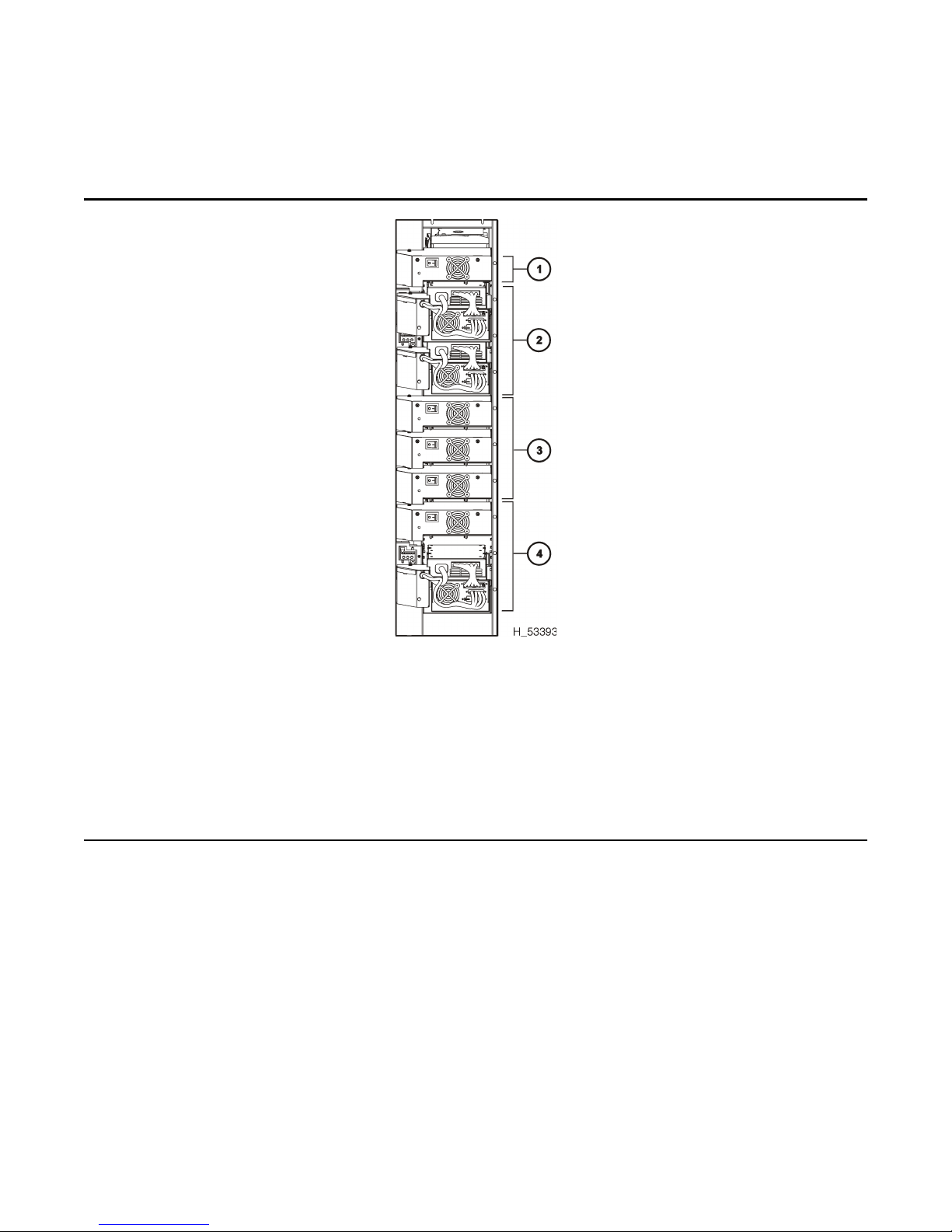
Refer to Figure 1 and the explanation below for the configuration rules for installing drives.
1. The first callout in Figure 1 shows that the uppermost drive slot in the drive column can only be a
DLT drive.
2. The second callout depicts the size ratio of the 9840 drives to the DLT drives. In size, two
9840 drives fit in the same space as three DLT drives.
3. The third callout shows thi s ratio again: thr ee DLT drives fit in the same space as two 9840
drives.
4. The fourth callout depicts a mixture of 9840 and DLT drives.
You may also install six 9840 drives plus one DLT drive in a column, where the DLT
drive occupies the top drive slot.
The following table lists the available combinations for one drive column.
9840 DLT
010
18
27
35
44
52
61
Page 5
62114 5
Figure 1. Tape Drive Installation Guideli nes
Tape Drive Installation Guidelines (H_53393)
1. DLT drive only in this position
2. Two 9840 drives (shown) or three DLT drives
3. Three DLT drives (shown) or two 9840 drives
4. Mixed 9840 and DLT drives (shown), three DLT drives, or two 9840 drives
NOTE:This graphic depicts the size relationship between DLT and 9840 drives ONLY.
Installation instructions call for installing the 9840 drives in the bottom slots, and the
DLT drives in the upper slots.
Page 6

62114 6
■ Installing DLT Drives
For DLT drives, follow the procedure below to unpack and install the drives.
DLT tape drives are shipped with the following, non-selectable configurations:
• DLT8000 (manufacturer’s model number)
• Differential operation
Refer to Figure 2 and make sure that the labels on the drive match the drive type and
operation required.
NOTE:Check with the customer for their maintenance agreement on tape drives. If
the customer agreement is to return the drives for repair, have them retain
one shipping box, with packing material, to be sent back to the factory.
Figure 2. DLT Labe ls
DLT Labels (H_65115)
1. Manufacturer’s model number label
2. Differential label (and drive serial number)
Page 7

62114 7
NOTE:Refer to Figure 3 for the following procedure.
CAUTION: DL T equipment damage: Do not move the load latch of a tape drive by
hand until t old to do so in later instructions .
1. Open the drive access section of the library (at the right side, as viewed from the front of
the library) by lifting up on the two latches. Turn the latches counterclockwise and open
the side door.
2. Open the drive package.
3. Remove the packing material.
4. Refer to Figure 3 while checking the side of the DLT drive for the terminating power
jumper selection.
CAUTION: Loss of data or degradation of performance: HP rec ommends
supplyin g t erm inating pow er (TERMPW R ) f rom devices attached at bot h ends of
the SCSI bus. Industry standards advi se th at no more than three device s p rov ide
terminating power to the bus.
Verify whether TERMPWR for DLT drives is on or off (enabled or disabled) for each
tape drive. If needed, move the jumper to match your requirement.
• TERMPWR On: Install the jumper on the pins shown in the following figure.
• TERMPWR Off: Remove the jumper on the pins shown in the following figure.
You can store the strap by placing it on one pin only.
NOTE:You may need to remove the DLT drive from its library tray to gain
access to this jumper. If removal is required, carefully turn the driv e
upside down and remove drive mounting screws. Change the jumper
as required. Replace the drive mounting screws.
5. Carefully place each drive near the rear slots at the right side of the libra ry.
Page 8

62114 8
6. Look inside the drive column area and determine the slot you wish to use for each drive.
Following the lifting procedures described in Chapter 2 “Safety and ESD”, of the Instal-
lation Manual firmly grasp the drive at the rear with one hand and place the other hand
under the drive mounting plate .
7. Carefully guide the drive into its slot. Push it in as far as it will go and firmly seat the
drive.
NOTE:In the following step, do not over tighten the thumbscrew.
8. Refer to Figure 4 and turn the thumbscrew clockwise until it is secure.
Figure 3. Terminating Power Jumper DLT Drive
Terminating Power Jumper—DLT Drive (H_65116)
1. DLT drive
2. Load latch
3. TERMPWR jumper (enabled)
Page 9

62114 9
Figure 4. Tape Drives Rear View
I
Tape Drives—Rear View (H_65124)
1. DLT power switch
2. Thumbscrews
3. 9840 power switch
Page 10

62114 10
■ Installing DLT Cable Connectors
The following procedures describe how to install the tape channel connectors for the tape
drives.
Standard Drive Column 0 Connectors.
NOTE:Drive column 0 is the standard drive column included in all librarie s . It is
the column that contains the calibra tion label at the bottom. Also, some
of the following steps may require two people.
1. Go to the rear of the library, open the door, and locate the connect or bulkhead.
2. Remove the SCSI “Y” channel cable and mounting screws from the drive box.
3. Refer to Figure 5 and insert the two channel connector s into the slots on the interior library
bulkhead, next to the desired drive location.
4. From the rear bulkhead, thread the four mounting screws into the connectors .
5. Tight en the mounting screws with a 3/16-inch nutdriver.
6. Insert the single connector end into the DLT drive.
7. Repeat these s te ps for al l driv es in column 0.
8. When you are finished installing all drives, place the drive power switch(es) to the ON (|)
position.
9. Close the rear door.
Figure 5. T ape Drive Cable Connectors
Tape Drive Cable Connectors (H_65226)
1. Interior bulkhead view
2. Exterior bulkhead vie w
Page 11

62114 11
Optional Drive Column 1 Connectors
NOTE:This section applies to the 20/700 tape library only.
1. Open the small access door (loc ated on the frame member between the two drive columns) for the
column 1 drive connectors by turning the five snap rings counterclockwise.
2. Repeat the steps in the section above to install the channel connectors and drive connec-
tors.
3. Place the drive power switc h(es) to the ON (|) position.
4. When all connectors are in place, close and lock the small access door.
Page 12

62114 12
■ Installing the Host Interface Cables
NOTE:Term Power is not supplied by the DLT; it must be supplied by the Host Bus
Adapter card.
To install SCSI cables:
The DLT connects to a SCSI bus and supports only the differential alternative.
All host systems should have either the SCSI ports labeled or the international symbols
displayed to indicate the electrical configuration for that port.
CAUTION: Maxi m um cable length. The maxi m um cable length for the di fferential
alternative is 25 m (82 ft). Make sure that the total cable length (including all daisy-chain
cables) from the host to the last device does not exceed the maximum length.
1. Record the device address. The default value of the
device address is five.
2. Route all the SCSI cable(s) from the host to the
library.
NOTE:Do not attach either end of the cable(s) at
this time.
Page 13

62114 13
NOTE:Ensure that all previous tasks have been completed before attaching the
SCSI terminators.
3. Route the cable for the first drive through the cutout
in the library floor.
NOTE: Use the figure to th e r i g h t fo r an
example. Although the figure shows
Column 1 locations, the locations for
Colum n 0 ar e very simila r.
CAUTION: Connector damage. Be car eful n ot to
bend or da m age the pins or co nnectors whe n
connecting the cable to the driv e or SCSI bul k head.
4. Connect the cable to a 68-pin jack on the library
bulkhead.
NOTE: If you are attaching to a 50-pin SCSI bus,
an adapter is required.
5. Connect a 6 in. daisy-chain cable from the second
68-pin connector to the Y-cable connector for the
next drive, if applicable. See the figure to the right
for an example.
6. Install the terminator either at the bulkhead jack or
to the device at the end of the SCSI bus.
7. Repeat steps 2 through 6 for all remaining drives, as
applicable.
8. Close and lock the small access door, if drives were
installed in Column 1.
Page 14

62114 14
■ SCSI Drive Connections
For SCSI operation, make sure that you comply with the length restrictions for your
channel type.
It is very important to label each drive with its host address. It is also important to label the
cables. These labels provide reliable identification for any future maintenance on the
drives.
CAUTION: Do not connect SCSI cables to the drives until they are configured for
operation.
Direct Con n e ction
For installations requiring SCSI direct data path configurations, for each drive:
1. Open the left rear door.
2. Connect the host data cable to the appropriate connector at the rear library frame for the
first drive.
3. Make sure a terminator is installed on the second drive connector at the rear library frame:
Daisy Chain Connection
NOTE: Bus Constraints
• 1 9840 drive plus (optionally) library robotics
• 1 DLT8000 drive plus (optionally) library robotics
CAUTION: For maximu m performance the above b us c onstraints mus t b e fo llowed.
Additionally , sharing of the bus with other devices is not recommended--device bus resets
may cause failure of the backup operation.
For installations requiring SCSI daisy–chain data path configurations:
1. Open the left rear door.
2. Connect the host data cable to the appropriate connector at the rear libra ry frame.
3. At the rear of the libr ary frame, install a short SCS I jumper cable from the second conne ctor of the first drive to the next drive connector in the chain:
4. Continue the chain until you rea ch the last drive on the chain.
5. Make sure a terminator is installed on the last drive connector on the rear librar y frame.
Page 15

62114 15
■ Turning the System Over to the Customer
After the DLT drive has been installed and all testing has been completed, it is time to turn
the system over to the customer. Follow these steps:
1. Place the drive online (see Chapter 4 of the Installation Manual).
2. Return to the library installation docum entation and compl ete the library install, if applicable.
NOTE:Library configuration m us t be updated to identify DLT drives and
cartridge arrays may need to be installed.
3. Give the DLT 8000 Tape System Product Manual to the cu s t omer.
4. Provide the operator with training on the DLT drive.
5. Provide training on how to place a servic e cal l.
Page 16

62114
REV C
EC 111770
Copyright ©2001
Hewlett-Packard Company/
Storage Technology Corp
Edition 11/2001
 Loading...