

Page 1
hp surestore
interface manager
installation and
cabling
10
11
20
19
17
16
15
14
13
12
18
12
Slot #
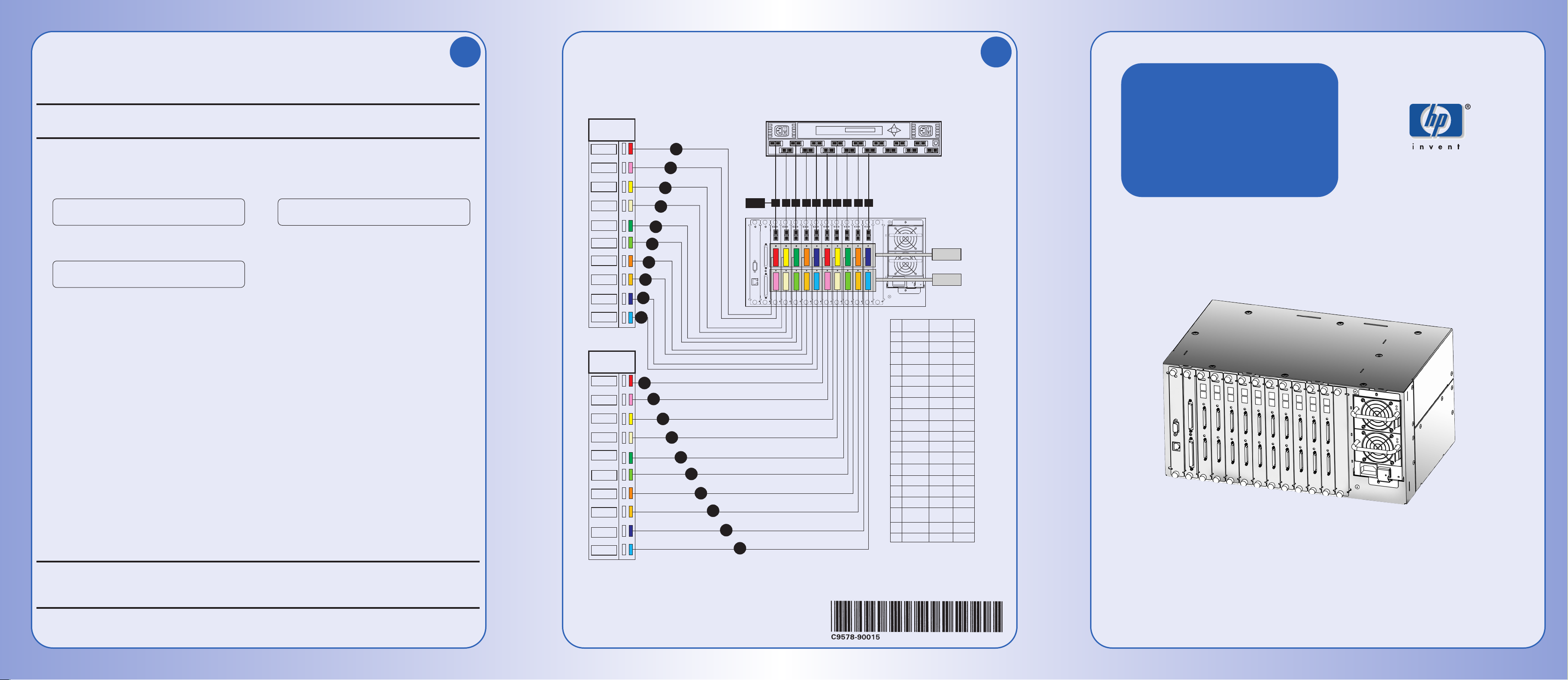
Installing SCSI Cables
Before iinstalling tthe SSCSI ccables, rrefer tto CChapter 33 ((Installation) iin tthe HHP SSurestore IInterface
Manager IInstallation aand SService GGuide ffor IIMPORTANT iinformation oon iinstalling SSCSI ccables.
CAUTION:
Turn off all devices before making SCSI connections. Failure to turn off all power could
result in damage to the devices.
1) Begin with Slot 3, Bus1: Connect a SCSI cable to Bus 1 on the Fibre Channel interface card
located in Slot 3. Locate the two matching labels in the cable label kit.
For the
hp
surestore 20/700 tape library:
For the
hp
surestore 10/180 tape library:
On the label, write the number of the drive you will be connecting this cable to. Attach one label to
each end of the SCSI cable. Connect the other end of the SCSI cable to your chosen drive.
2) Proceed with Slot 3,Bus 2; Slot 4, Bus1; Slot 4, Bus 2, until all drives have been properly
connected.
3) Install the appropriate SCSI terminators on all remaining SCSI connectors on the drives. The
Interface Manager Fibre Channel interface cards have internal termination, so no termination is
needed at the interface card end.
4) You may connect the library’s robotics controller to the last spare bus on one of the Fibre Channel
interface cards, or daisy chain it with the first tape drive as long as the library robotics controller
and the tape drive are of the same SCSI bus type (HVD to HVD, LVD to LVD).
NOTE:
Use the HVD to LVD converter (HP A6324A) to connect the library’s robotics controller to
an LVD SCSI bus.
5) Confirm that all cable ends are connected and labeled securely and that each drive is properly
terminated. The Interface Manager, in its default configuration, provides internal termination at the
end of each SCSI bus.
CAUTION:DO NNOT
connect fibre or network cables yet as the addressing modes and IP addresses
need to be checked prior to installation. See the
HP SSurestore IInterface MManager
Installation aand SService GGuide
for more information.
or
Column 0 Drive ___ Column 0 Drive ___
Slot 3, Bus 1 Slot 3, Bus 1
Drive ___ Drive ___
Slot 3, Bus 1 Slot 3, Bus 1
Column ___ Drive ___ Column ___ Drive ___
Slot ___ Bus ___ Slot ___ Bus ___
Data subject to change
2001 Hewlett-Packard Company
Printed in USA 12/2001
support and product information: www.hp.com/go/support
Cabling Diagram for
hp surestore 20/700 library
2
6
Drive
Column 0
DRIVE 00
DRIVE 01
DRIVE 02
DRIVE 03
DRIVE 04
DRIVE 05
DRIVE 06
DRIVE 07
DRIVE 08
DRIVE 09
T = Terminator
Drive
Column 1
DRIVE 10
DRIVE 11
DRIVE 12
DRIVE 13
DRIVE 14
DRIVE 15
DRIVE 16
DRIVE 17
DRIVE 18
DRIVE 19
T
T
T
T
T
T
T
7
T
8
9
T
T
10
T
11
T
T
T
T
T
T
T
T
T
6
12
1
2
3
4
5
13
14
15
16
17
18
Slot #
19
20
1
3 654
0
3
4
2
5
7 9 11 13 15
7 9 1010111112
8
6 8 10 12 14
01
Drive 0 Slot 3 Bus 1
02
Drive 1 Slot 3 Bus 2
03
Drive 2 Slot 4 Bus 1
04
Drive 3 Slot 4 Bus 2
05
Drive 4 Slot 5 Bus 1
06
Drive 5 Slot 5 Bus 2
07
Drive 6 Slot 6 Bus 1
08
Drive 7 Slot 6 Bus 2
09
Drive 8 Slot 7 Bus 1
10
Drive 9 Slot 7 Bus 2
11
Drive 10 Slot 8 Bus 1
12
Drive 11 Slot 8 Bus 2
13
Drive 12 Slot 9 Bus 1
14
Drive 13 Slot 9 Bus 2
15
Drive 14 Slot 10 Bus 1
16
Drive 15 Slot 10 Bus 2
17
Drive 16 Slot 11 Bus 1
18
Drive 17 Slot 11 Bus 2
19
Drive 18 Slot 12 Bus 1
20
Drive 19 Slot 12 Bus 2
Bus 1
Bus 2
T = Terminator
Page 2
DRIVE 00
DRIVE 01
Drive 0
Slot 3, Bus1
Drive 0
Slot 3, Bus1
Terminator
Bus 1
7 9 1010 1111 12128
Slot #
Bus 2
3 654
Bus and Slot Locations
SCSI Cable Label Placement
Bus 2
Bus 1
DRIVE 0
DRIVE 1
DRIVE 2
DRIVE 3
DRIVE 4
DRIVE 5
DRIVE 6
DRIVE 7
DRIVE 8
DRIVE 9
10/180
LIBRARY
T
1
1010
9
8
7
6
4
3
2
T = Terminator
T
T
T
T
T
T
T
T
T
5
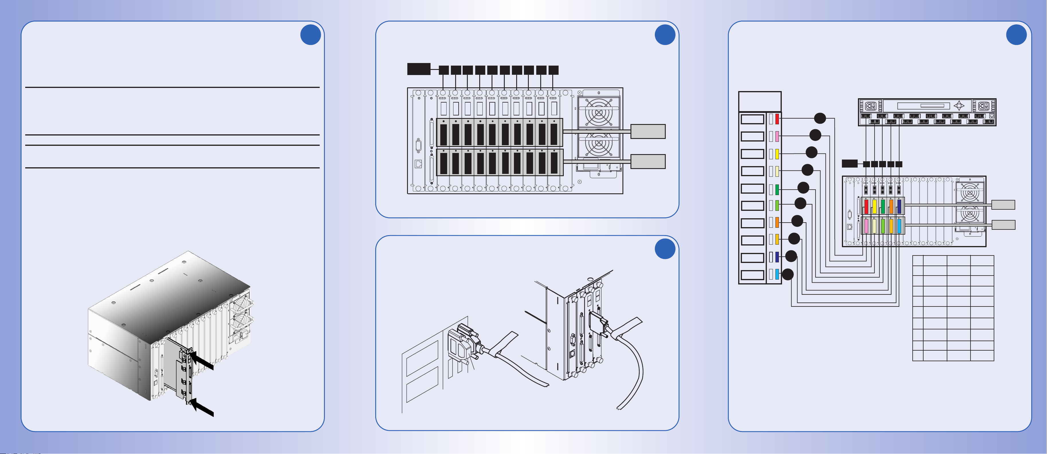
Drive 0 Slot 3 Bus 1
Drive 1 Slot 3 Bus 2
Drive 2 Slot 4 Bus 1
Drive 3 Slot 4 Bus 2
Drive 4 Slot 5 Bus 1
Drive 5 Slot 5 Bus 2
Drive 6 Slot 6 Bus 1
Drive 7 Slot 6 Bus 2
Drive 8 Slot 7 Bus 1
Drive 9 Slot 7 Bus 2
01
02
03
04
05
06
07
08
09
10
4
5
6
7
Slot #
3
4
3
0
1
2
5
6 8 10 12 14
79111315
Cabling Diagram for
hp surestore 10/180 library
Installing Fibre Channel Interface Cards
Before iinstalling tthe FFibre CChannel iinterface ccards, rrefer tto CChapter 33 ((Installation) iin tthe HHP
Surestore IInterface MManager IInstallation aand SService GGuide ffor IIMPORTANT iinformation rregarding
the iinstallation oof FFibre CChannel iinterface ccards.
CAUTION:
Standard performance Fibre Channel interface cards are
NOT
supported in the Interface
Manager. The unsupported cards have part numbers C7200-60x09 and C7200-60x16.
These can be easily identified because they have the larger 68-pin SCSI bus connectors.
Inserting these cards into the Interface Manager will result in blowing a fuse, which will
require the replacement of the entire Interface Manager chassis.
CAUTION:
Turn off all devices before making SCSI connections. Failure to turn off all power could
result in damage to the devices.
To install a Fibre Channel interface card:
1) Remove the card slot covers from all slots where a Fibre Channel interface card will be installed.
2) Gently push the card into place by applying pressure on the top
AND
bottom of the card until it is
flush with the chassis. Pushing the card in from the top
OR
bottom alone may damage the card
or the Interface Manager.
1
3
5
4
 Loading...