

Page 1

SuperStack®3
Firewall
User Guide
SuperStack 3 Firewall 3CR16110-95
SuperStack 3 Firewall Web Site Filter 3C16111
http://www.3com.com/
Part No. DUA1611-0AAA02
Published August 2001
Page 2

3Com Corporation
5400 Bayfront Plaza
Santa Clara, California
95052-8145
Copyright © 2001, 3Com Technologies. All rights reserved. No part of this documentation may be reproduced
in any form or by any means or used to make any derivative work (such as translation, transformation, or
adaptation) without written permission from 3Com Technologies.
3Com Technologies reserves the right to revise this documentation and to make changes in content from time
to time without obligation on the part of 3Com Technologies to provide notification of such revision or
change.
3Com Technologies provides this documentation without warranty, term, or condition of any kind, either
implied or expressed, including, but not limited to, the implied warranties, terms or conditions of
merchantability, satisfactory quality, and fitness for a particular purpose. 3Com may make improvements or
changes in the product(s) and/or the program(s) described in this documentation at any time.
If there is any software on removable media described in this documentation, it is furnished under a license
agreement included with the product as a separate document, in the hard copy documentation, or on the
removable media in a directory file named LICENSE.TXT or !LICENSE.TXT. If you are unable to locate a copy,
please contact 3Com and a copy will be provided to you.
UNITED STATES GOVERNMENT LEGEND
If you are a United States government agency, then this documentation and the software described herein are
provided to you subject to the following:
All technical data and computer software are commercial in nature and developed solely at private expense.
Software is delivered as “Commercial Computer Software” as defined in DFARS 252.227-7014 (June 1995) or
as a “commercial item” as defined in FAR 2.101(a) and as such is provided with only such rights as are
provided in 3Com’s standard commercial license for the Software. Technical data is provided with limited rights
only as provided in DFAR 252.227-7015 (Nov 1995) or FAR 52.227-14 (June 1987), whichever is applicable.
You agree not to remove or deface any portion of any legend provided on any licensed program or
documentation contained in, or delivered to you in conjunction with, this User Guide.
Unless otherwise indicated, 3Com registered trademarks are registered in the United States and may or may not
be registered in other countries.
3Com and SuperStack are registered trademarks of 3Com Corporation. The 3Com logo and CoreBuilder are
trademarks of 3Com Corporation.
Intel and Pentium are registered trademarks of Intel Corporation. Microsoft, MS-DOS, Windows, and Windows
NT are registered trademarks of Microsoft Corporation. Novell and NetWare are registered trademarks of
Novell, Inc. UNIX is a registered trademark in the United States and other countries, licensed exclusively
through X/Open Company, Ltd.
Netscape Navigator is a registered trademark of Netscape Communications.
JavaScript is a trademark of Sun Microsystems
All other company and product names may be trademarks of the respective companies with which they are
associated.
ENVIRONMENTAL STATEMENT
It is the policy of 3Com Corporation to be environmentally-friendly in all operations. To uphold our policy, we
are committed to:
Establishing environmental performance standards that comply with national legislation and regulations.
Conserving energy, materials and natural resources in all operations.
Reducing the waste generated by all operations. Ensuring that all waste conforms to recognized environmental
standards. Maximizing the recyclable and reusable content of all products.
Ensuring that all products can be recycled, reused and disposed of safely.
Ensuring that all products are labelled according to recognized environmental standards.
Improving our environmental record on a continual basis.
End of Life Statement
3Com processes allow for the recovery, reclamation and safe disposal of all end-of-life electronic components.
Regulated Materials Statement
3Com products do not contain any hazardous or ozone-depleting material.
Environmental Statement about the Documentation
The documentation for this product is printed on paper that comes from sustainable, managed forests; it is
fully biodegradable and recyclable, and is completely chlorine-free. The varnish is environmentally-friendly, and
the inks are vegetable-based with a low heavy-metal content.
Page 3

C
ONTENTS
A
BOUTTHISGUIDE
How to Use This Guide 12
Conventions 12
Terminology 13
Feedback about this User Guide 15
Registration 16
ETTINGSTARTED
IG
I
NTRODUCTION
1
What is the SuperStack 3 Firewall? 19
Firewall and 3Com Network Supervisor 20
Firewall Features 21
Firewall Security 21
Web URL Filtering 23
High Availability 24
Logs and Alerts 24
User Remote Access (from the Internet) 24
Automatic IP Address Sharing and Configuration 24
Introduction to Virtual Private Networking (VPN) 25
Virtual Private Networking 25
I
NSTALLING THEHARDWARE
2
Before You Start 27
Positioning the Firewall 28
Rack Mounting the Units 28
Securing the Firewall with the Rubber Feet 29
Firewall Front Panel 29
Firewall Rear Panel 31
Page 4

Redundant Power System (RPS) 31
Attaching the Firewall to the Network 32
3
II C
UICKSETUP FOR THEFIREWALL
Q
Introduction 35
Setting up a Management Station 36
Configuring Basic Settings 36
Setting the Password 37
Setting the Time Zone 38
Configuring WAN Settings 39
Automatic WAN Settings 39
Manual WAN Settings 40
Using a Single Static IP Address 41
Using Multiple Static IP Addresses 42
Using an IP Address provided by a PPPoE Server 44
Using a Static IP address provided by a DHCP Server 44
Configuring LAN Settings 44
Automatic LAN Settings 44
Entering information about your LAN 45
Configuring the DHCP Server 45
Confirming Firewall Settings 46
ONFIGURING THEFIREWALL
4
ASICSETTINGS OF THEFIREWALL
B
Examining the Unit Status 52
Setting the Administrator Password 53
Setting the Inactivity Timeout 54
Setting the Time 54
Changing the Basic Network Settings 56
Setting the Network Addressing Mode 56
Specifying the LAN Settings 57
Specifying the WAN/DMZ Settings 58
Specifying the DNS Settings 59
Specifying DMZ Addresses 59
Setting up the DHCP Server 60
Page 5

Global Options 61
Dynamic Ranges 62
Static Entries 63
Viewing the DHCP Server Status 63
Using the Network Diagnostic Tools 64
Choosing a Diagnostic Tool 64
ETTING UPWEBFILTERING
5
S
Changing the Filter Settings 67
Restricting the Web Features Available 68
Setting Blocking Options 69
Specifying the Categories to Filter 69
Specifying When Filtering Applies 70
Filtering Web Sites using a Custom List 70
Setting up Trusted and Forbidden Domains 71
Changing the Message to display when a site is blocked 72
Updating the Web Filter 73
Checking the Web Filter Status 73
Downloading an Updated Filter List 74
Setting Actions if no Filter List is Loaded 74
Blocking Websites by using Keywords 75
Filtering by User Consent 75
Configuring User Consent Settings 76
Mandatory Filtered IP addresses 77
6
SING THEFIREWALLDIAGNOSTICTOOLS
U
Logs and Alerts 79
Viewing the Log 80
Changing Log and Alert Settings 82
Sending the Log 83
Changing the Log Automation Settings 84
Selecting the Categories to Log 85
Alert Categories 86
Generating Reports 87
Collecting Report Data 87
Viewing Report Data 88
Restarting the Firewall 89
Page 6

Managing the Firewall Configuration File 90
Importing the Settings File 91
Exporting the Settings File 92
Restoring Factory Default Settings 92
Using the Installation Wizard to reconfigure the Firewall 92
Upgrading the Firewall Firmware 92
ETTING APOLICY
7
S
Changing Policy Services 97
Amending Network Policy Rules 98
Changing NetBIOS Broadcast Settings 99
Enabling Stealth Mode 100
Allowing Fragmented Packets 100
Adding and Deleting Services 101
Editing Policy Rules 103
Viewing Network Policy Rules 103
Adding a New Rule 106
Restoring Rules to Defaults 106
Updating User Privileges 106
Establishing an Authenticated Session 108
Setting Management Method 109
Selecting Remote Management 110
Using the Firewall with the NBX 100 Business Telephone System 110
8
9
DVANCEDSETTINGS
A
Automatic Proxy/Web Cache Forwarding 111
Deploying the SuperStack 3 Webcache as a Proxy of the Firewall 112
Specifying Intranet Settings 114
Installing the Firewall to Protect the Intranet 115
Configuring the Firewall to Protect the Intranet 115
Setting Static Routes 117
Setting up One-to-One NAT 119
ONFIGURINGVIRTUALPRIVATENETWORKSERVICES
C
Editing VPN Summary Information 123
Changing the Global IPSec Settings 124
Page 7

Viewing the Current IPSec Security Associations 125
Configuring a VPN Security Association 125
Adding/Modifying IPSec Security Associations 126
Security Policy 127
Setting the Destination Network for the VPN Tunnel 131
Configuring the Firewall to use a RADIUS Server 132
Changing the Global RADIUS Settings 132
Changing RADIUS Server Details 133
Using the Firewall with Check Point Firewall-1 134
Configuring the IRE VPN Client 134
Configuring the Firewall 137
Configuring the IRE VPN Client for use with the Firewall 137
Setting up the GroupVPN Security Association 138
Installing the IRE VPN Client Software 139
Configuring the IRE VPN Client 139
10
III A
11
ONFIGURINGHIGHAVAILABILITY
C
Getting Started 141
Network Configuration for High Availability Pair 142
Configuring High Availability 142
Configuring High Availability on the Primary Firewall 143
Configuring High Availability on the Backup Firewall 144
Making Configuration Changes 145
Checking High Availability Status 146
High Availability Status Window 146
E-Mail Alerts Indicating Status Change 147
View Log 147
Forcing Transitions 148
DMINISTRATION ANDTROUBLESHOOTING
DMINISTRATION ANDADVANCEDOPERATIONS
A
Introducing the Web Site Filter 153
Activating the Web Site Filter 156
Using Network Access Policy Rules 157
Understanding the Rule Hierarchy 158
Page 8

Examples of Network Access Policies 159
Resetting the Firewall 162
Resetting the Firewall 163
Reloading the Firmware 163
Direct Cable Connection 164
Direct Connection Instructions 165
12
ROUBLESHOOTINGGUIDE
T
Introduction 167
Potential Problems and Solutions 167
Power LED Not Lit 167
Power LED Flashes Continuously 168
Power and Alert LED Lit Continuously 168
Link LED is Off 168
Ethernet Connection is Not Functioning 168
Cannot Access the Web interface 168
LAN Users Cannot Access the Internet 169
Firewall Does Not Save Changes 169
Duplicate IP Address Errors Are Occurring 169
Machines on the WAN Are Not Reachable 170
Troubleshooting the Firewall VPN Client 170
The IKE Negotiation on the VPN Client 170
Restarting the Firewall with Active VPN Tunnel 171
Export the VPN Client Security Policy File 171
Import the VPN Client Security Policy File 171
Uninstall the VPN Client 171
Frequently Asked Questions about PPPoE 172
IV F
13
IREWALL ANDNETWORKINGCONCEPTS
YPES OFATTACK ANDFIREWALLDEFENCES
T
Denial of Service Attacks 175
Ping of Death 175
Smurf Attack 175
SYN Flood Attack 176
Land Attack 176
Page 9

Intrusion Attacks 176
External Access 176
Port Scanning 177
IP Spoofing 177
Trojan Horse Attacks 177
14
VA
A
ETWORKINGCONCEPTS
N
Introduction to TCP/IP 179
IP and TCP 179
IP Addressing 179
Network Address Translation (NAT) 182
Limitations of Using NAT 182
Dynamic Host Configuration Protocol (DHCP) 183
Port Numbers 184
Well Known Port Numbers 184
Registered Port Numbers 184
Private Port Numbers 184
Virtual Private Network Services 184
Introduction to Virtual Private Networks 185
VPN Applications 185
Basic VPN Terms and Concepts 186
PPENDICES
AFETYINFORMATION
S
Important Safety Information 193
Wichtige Sicherheitshinweise 194
Consignes Importantes de Sécurité 195
ECHNICALSPECIFICATIONS ANDSTANDARDS
B
T
C
ABLESPECIFICATIONS
C
Cable Specifications 199
Pinout Diagrams 199
Page 10

D
ECHNICALSUPPORT
T
Online Technical Services 201
World Wide Web Site 201
3Com Knowledgebase Web Services 201
3Com FTP Site 202
Support from Your Network Supplier 202
Support from 3Com 202
Returning Products for Repair 204
NDEX
I
EGULATORYNOTICES
R
Page 11
A
BOUTTHIS
This guide describes the following products:
■
SuperStack 3 Firewall 3CR16110-95
■
SuperStack 3 Firewall 3CR16110-97 upgraded to v6.x firmware
■
SuperStack 3 Firewall Web Site Filter 3C16111
G
UIDE
Introduction This guide describes how to set up and maintain the SuperStack
Firewall and how to install and use the SuperStack 3 Web Site Filter.
The Firewall acts as a secure barrier to protect a private LAN from hacker
attacks from the Internet. It can also be used to control the access that
LAN users have to the Internet.
The Web Site Filter controls and monitors the access users have to web
sites. Sites can be blocked on a site-wide or individual basis and by the
features a web site uses or content it provides.
This guide is intended for use by the person responsible for installing or
managing the network. It assumes knowledge of the following:
■
Basic familiarity with Ethernet networks and the Internet Protocol.
■
Knowledge of how to install and handle electronically sensitive
equipment.
If release notes are shipped with your product and the information there
differs from the information in this guide, follow the instructions in the
release notes.
Most user guides and release notes are available in Adobe Acrobat
Reader Portable Document Format (PDF) or HTML on the 3Com
World Wide Web site:
http://www.3com.com/
®
3
Page 12
12 ABOUT THIS GUIDE
How to Use This Guide
Table 1 shows where to look for specific information in this guide.
Ta b l e 1
If you are looking for... Turn to...
A description of the Firewall’s features and example
applications.
A description of the Firewall’s front and back panel displays and
connectors, and installation information.
A quick setup guide for the Firewall. Chapter 3
Information on how to configure the Firewall. Chapter 4 -
Information about installing and setting up the Web Site Filter. Chapter 11
Troubleshooting common Firewall problems. Chapter 12
Information about Denial of Service and other attacks. Chapter 13
An introduction to TCP/IP and VPN. Chapter 14
Important Safety Information. Appendix A
Technical Specifications of the Firewall. Appendix B
Cable Specifications. Appendix C
Information about obtaining Technical Support. Appendix D
Where to find specific information
Chapter 1
Chapter 2
Chapter 10
Conventions
Table 2 and Table 3 list conventions that are used throughout this guide.
Ta b l e 2
Icon Notice Type Description
Notice Icons
Information note Information that describes important features or
instructions.
Caution
Warning
Information that alerts you to potential loss of
data or potential damage to an application,
system, or device.
Information that alerts you to potential personal
injury.
Page 13

Terminology 13
Ta b l e 3
Convention Description
Screen displays
Commands
The words “enter”
and “type”
Keyboard key names If you must press two or more keys simultaneously, the
Words in italics Italics are used to:
Text Conventions
This typeface represents information as it appears on
the screen.
The word “command” means that you must enter the
command exactly as shown and then press Return or
Enter. Commands appear in bold. Example:
To display port information, enter the following
command:
bridge port detail
When you see the word “enter” in this guide, you
must type something, and then press Return or Enter.
Do not press Return or Enter when an instruction
simply says “type.”
key names are linked with a plus sign (+). Example:
■
■
■
Press Ctrl+Alt+Del
Emphasize a point.
Denote a new term at the place where it is defined
in the text.
Identify menu names, menu commands, and
software button names. Examples:
From the Help menu, select Contents.
Click OK.
Terminology
This section lists terminology used in this guide.
DMZ — Demilitarized Zone port. The Firewall has an extra port. If you
connect publicly-accessible servers and workstations to this port, they are
accessible from the Internet but still protected from Denial of Service
attacks
DoS Attacks — Denial of Service Attacks. An attempt to stop one of
your services running, such as a Web or FTP server. There are several kinds
of DoS attacks.
IP address — The Internet Protocol address is the network layer address
of a device assigned by the user or network administrator of an IP
network. An IP address consists of 32 bits divided into two or three fields:
Page 14

14 ABOUT THIS GUIDE
a network number and a host number, or a network number, a subnet
number, and a host number.
IP Spoof — AtypeofDoSattack.AnIPspoofusesafakeIPaddressto
bypass security settings which may bar access from the real IP address.
IRC — Internet Relay Chat. Provides a way of communicating in real time
with people from all over the world.
ISP — Internet Service Provider. A business that provides Internet access
to individuals or organizations.
Firewall — Used in this guide to refer to the SuperStack 3 Firewall.
Land Attack — A type of DoS attack. In a Land attack, a packet is sent
that appears to come from the same address and port that it is sent to.
Thiscanhangthemachinetowhichitissent.
Management Station — This is the workstation from which you run the
Web interface for the Firewall.
Web interface — This is the Web-based application which you use to set
up the Firewall to protect your network from attack and to control access
to the Internet for LAN users.
NAT — Network Address Translation. NAT refers to the process of
converting the IP addresses used within a private network to Internet IP
addresses.
NTP — Network Time Protocol. This allows the Firewall to automatically
set the local time, via an NTP server on the Internet
NNTP — Network News Transfer Protocol. This protocol is used to
distribute Usenet news articles over the Internet.
Ping of Death — A type of DoS attack. The Internet Protocol (IP) defines
the maximum size for a Ping packet. However, some Ping programs can
send packets that are larger than this size which can cause some systems
to crash.
PPPoE — PPPoE stands for Point-to-Point Protocol over Ethernet and is
based on two widely accepted standards, Point-to-Point Protocol (PPP)
and Ethernet. PPPoE is a method for personal computers to connect to a
broadband service (typically DSL).
Page 15
Feedback about this User Guide 15
RADIUS — Remote Authentication Dial-in User Service. RADIUS enables
network administrators to effectively deploy and manage VPN Client
based remote users. The RADIUS server allows multiple users to share a
single Group Security Association but require an additional unique
password for accounting and access.
SYN Flood — A type of DoS attack. This is where a client opens a
connection with a server but does not complete it. If the server queue fills
up with partially-open connections, no other clients can make genuine
connections to that server.
UTC —stands for Universal Time Co-ordinated, and is the standard time
common to all places in the world. It is also commonly referred to as GMT
or World Time.
VPN — stands for Virtual Private Network, and is a method of
networking that uses data encryption and the public internet to provide
secure communications between sites without incurring the expense of
leased lines.
Feedback about this User Guide
Web Site Filter — Used in this guide to refer to the SuperStack 3 Web
Site Filter.
See Chapter 13, “Types of Attack and Firewall Defences” for further
information on types of attack and how the Firewall defends against
them.
Your suggestions are very important to us. They will help make our
documentation more useful to you. Please e-mail comments about this
document to 3Com at:
pddtechpubs_comments@3com.com
Please include the following information when commenting:
■
Document title
■
Document part number (on the title page)
■
Page number (if appropriate)
Example:
■
SuperStack 3 Firewall User Guide
Page 16
16 ABOUT THIS GUIDE
Part Number DUA1611-0AAA02
■
Page 24
■
Do not use this e-mail address for technical support questions. For
information about contacting Technical Support, see Appendix A.
Registration
To register your Firewall point your web browser to
http://www.3com.com/ssfirewall
click on Hardware Registration and follow the instructions.
Page 17

I
G
ETTING
Chapter 1 Introduction
Chapter 2 Installing the Hardware
Chapter 3 Quick Setup for the Firewall
S
TARTED
Page 18

18
Page 19

1
I
NTRODUCTION
This chapter contains the following:
■
What is the SuperStack 3 Firewall?
■
Firewall and 3Com Network Supervisor
■
Firewall Features
■
Introduction to Virtual Private Networking (VPN)
What is the
SuperStack 3
Firewall?
The SuperStack®3 Firewall is a dedicated firewall appliance which is
installed between a Private LAN and a Router. The Firewall is a complete
network security system with all hardware and software pre-installed.
This allows it to act as a secure gateway for all data passing between the
Internet and the LAN.
The purpose of the Firewall is to allow a private Local Area Network (LAN)
to be securely connected to the Internet. You can use the Firewall to:
■
Prevent theft, destruction, and modification of data.
■
Filter incoming data for unsafe or objectionable content.
■
Log events which may be important to the security of your network.
The Firewall has three Ethernet ports which are used to divide the
network into separate areas.
■
The Wide Area Network (WAN) port attaches to the Internet access
device, for example, Router or Cable Modem.
■
The Local Area Network (LAN) port attaches to the local network
through hubs and switches. LAN users have access to Internet services
such as e-mail, FTP, and the World Wide Web. However, all
workstations and data on the LAN are protected from hacker attacks
that might come through the WAN port.
Page 20
20 C
HAPTER
1: I
NTRODUCTION
The Demilitarized Zone (DMZ) port is used for public servers, such as
■
Web or FTP servers. Machines attached to this port are visible from the
WAN port, but are still protected from hacker attacks. Users on the
secure LAN port can also access servers on the DMZ port.
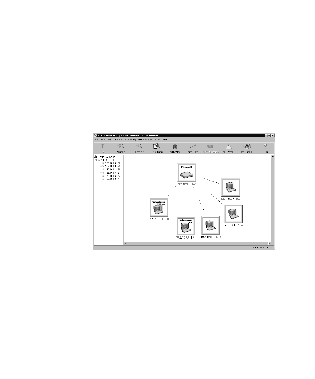
Firewall and 3Com Network Supervisor
The Firewall is supplied with a copy of 3Com Network Supervisor.
Network Supervisor is a powerful, intuitive network management
application for small to medium enterprise networks.
Figure 1
3Com Network Supervisor display
Network Supervisor automatically discovers up to 1500 network devices
and shows devices and connections on a graphical display. Network
managers can view network activity, monitor stress and set thresholds
and alerts. This information helps to provide the most efficient,
cost-effective use of network resources.
Version 3.0 and later releases add significant extra functionality designed
to detect network inefficiency and optimize network performance.
Features include support for related and recurring events, user definable
reports, auto-alerting using pager or SMS messages and simple updates
from the 3Com web site.
Page 21

Firewall Features 21
3Com Network Supervisor offers the following support to Firewall users:
■
If your 3Com Network Supervisor management station is located on
the LAN, it discovers the Firewall automatically and displays it on the
topology map.
■
The topology map indicates that the Firewall is a 3Com Firewall and
uses an appropriate icon to represent it.
■
Double-clicking on the Firewall icon launches the Web interface of the
Firewall.
If your 3Com Network Supervisor management station is located on the
WAN side of the Firewall you must follow the steps below before
Network Supervisor will detect your Firewall:
1 Access the Web interface from a Web browser connected to the LAN port
of the Firewall.
2 Click on the Policy button, after the Management screen appears.
3 Click on the User Privileges tab.
4 Add a user to the Current Privileges list. Enter the user name in the User
field.
5 Click on Remote Access and click Update Privileges.
Firewall Features
This section lists the features of the Firewall.
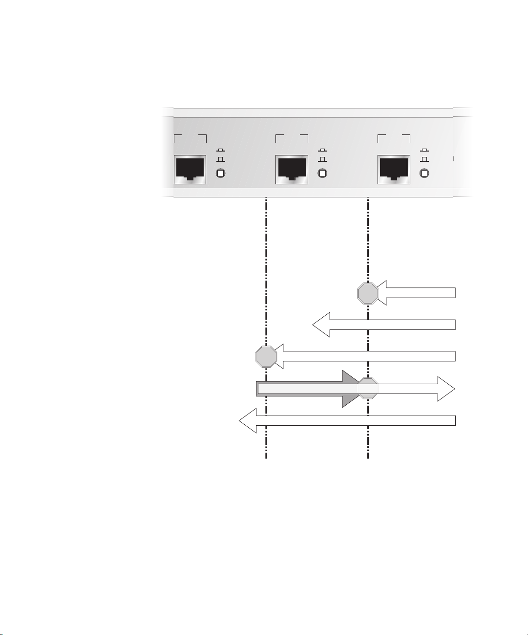
Firewall Security The Firewall is preconfigured to monitor Internet traffic, and detect and
block Denial of Service (DoS) hacker attacks automatically. Refer to
Figure 2.
Page 22
22 C
STOP
HAPTER
1: I
NTRODUCTION
Figure 2 Firewall Security Functions - Default Firewall Policy
LAN
Uplink
Normal
LAN Port - Connected
to your internal
network e.g. network
servers, workstations.
Protected from DoS
attacks and invisible from
outside your network.
DMZ
Uplink
Normal
DMZ Port - Connected
to public servers e.g.
Web, E-mail
Protected from DoS
attacks but visible from
outside your network.
STOP
Internet Access Filtered (optional)
Unauthorised External Access Blocked
WAN
WAN Port - Connected to
an external network or
the Internet via an
Internet access device.
The other ports are
protected from DoS attacks
originating on this port.
DoS Attacks Blocked
STOP
Web Access Allowed
STOP
Uplink
Normal
Authorised External Access using VPN (Encrypted)
LAN DMZ WAN
The Firewall examines every packet that comes from outside the LAN and
discards any packet that has not been authorized from inside the LAN.
This is known as stateful packet inspection.
Users on the LAN have access to all resources on the Internet that are not
blocked by any of the filters.
Users on the Internet can access hosts on the DMZ, such as a Web server,
but cannot access any resources on the LAN unless they are authorized
remote users.
Page 23

Firewall Features 23
The Firewall will protect your network against the following Denial of
Service attacks:
■
Ping of Death
■
Smurf Attack
■
SYN Flood
■
LAND Attack
■
IP Spoofing
■
Teardrop
To find more information on DoS and other attacks refer to Chapter 13,
“Types of Attack and Firewall Defences”
Advanced users can extend the security functions of the Firewall by
adding network access rules and user privileges. See “Examples of
Network Access Rules” on page 200 and “User Privileges” on page 205
for more information.
Web URL Filtering You can use the Firewall to monitor and restrict LAN users from accessing
inappropriate information on the Internet. You can block access to this
information or record attempts to access it in a log. See “Filter Settings”
on page 162 for more information.
You can create a list of all forbidden URLs to which you want to restrict
access. Alternatively, you can restrict access to the Internet to certain
trusted URLs. See “Setting up Trusted and Forbidden Domains” on
page 165 for more information.
Web site technologies such as cookies and Java and ActiveX applets give
enhancements to web pages, but hackers may use the technologies to
steal or damage data. The Firewall can block these potentially damaging
applications from being downloaded from the Internet, or allow them
only from trusted sites. See “Filter Settings” on page 162 for more
information.
You can also use the optional SuperStack 3 Web Site Filter to extend
these filtering capabilities of your Firewall. It provides a list of Web site
categories that might be considered inappropriate for business use. The
Web Site Filter updates the Firewall with the latest URLs matching the
selected categories. You can block access to these sites or log them. The
Firewall is supplied with a one-month free subscription. You can then
Page 24

24 C
HAPTER
1: I
NTRODUCTION
purchase a twelve month Web Site Filter (3C16111) subscription. Both
the trial and the twelve month subscription are valid for an unlimited
number of users.
High Availability Given the mission critical nature of many Internet connections each
component involved in your connection must be highly reliable. The High
Availability function of your Firewall adds to the already reliable platform
eliminating downtime due to hardware failure.
To u s e t h e High Availability function, connect another SuperStack 3
Firewall to the first as a high availability pair and configure the backup
Firewall to monitor the primary Firewall. In the event of failure of the
primary Firewall, the backup Firewall will take over its functions. See
“Configuring High Availability” on page 141 for details.
Logs and Alerts The Firewall maintains a log of all events that could be seen as security
concerns. It can also track key events such as the top 25 most accessed
Web sites, or the top 25 users of Internet bandwidth. You can also set up
the Firewall to send an alert message through e-mail when a high-priority
concern, such as a hacker attack, is detected. See “Log/Alert Settings” on
page 177 for more information.
User Remote Access
(from the Internet)
Automatic IP Address
Sharing and
Configuration
For detailed logging 3Com recommends that you us a syslog server or a
syslog reporting tool. A free syslog server is available from 3Com. To
download it point your web browser to:
http://www.3com.com/ssfirewall
and follow the link to the Syslog Server.
Users can access intranet resources on the private LAN by successfully
logging into the Firewall from the Internet. Logging in requires a valid
user name and password, which are transmitted to the Firewall by the
remote user, using a Web browser, through an MD5-based encrypted
authentication mechanism. Once logged in, remote users are able to
access all IP resources on the LAN
The Firewall provides sharing of a single public IP address through
Network Address Translation (NAT). It also provides simplified IP address
administration using the Dynamic Host Configuration Protocol (DHCP).
Page 25

Introduction to Virtual Private Networking (VPN) 25
NAT automatically translates multiple IP addresses on the private LAN to
one public address that is sent out to the Internet. It enables the Firewall
to be used with broadband modems such as the OfficeConnect Cable
Modem, and with low cost Internet accounts where only one IP address is
provided by the ISP. See “Network Addressing Mode” on page 149 for
more information.
The DHCP server automatically assigns all PCs on the LAN with the correct
IP information. The DHCP client allows the Firewall to acquire the correct
IP settings from the ISP. See “Setting up the DHCP Server” on page 155
for more information.
Introduction to Virtual Private Networking (VPN)
Virtual Private
Networking
The Firewall includes support for IPSec Virtual Private Networking. This
section provides an introduction to Virtual Private Networking (VPN).
Today’s business environment requires close, real-time collaboration with
trading partners, legal, and financial advisors, as well as remote workers
andbranchoffices.This“real-time” requirement often leads to the
creation of an “extranet” where branch offices and partners are
connected to a primary network in one of two ways:
■
Leasing dedicated data lines to connect all sites.
■
Using the public Internet to connect all sites and remote users
together.
Each of these methods has its benefits and drawbacks. Establishing a
leased line connection between the sites offers a dedicated, secure access
but at a very high cost.
The other option is to use an existing Internet connection to transmit data
unencrypted over the public Internet network. While this option is less
expensive and can provide higher performance, it is much less secure
than dedicated site-leased lines.
VPN uses data encryption and the public Internet to provide secure
communications between sites without incurring the huge expense of
site to site leased lines.
The Firewall embodies eight different levels of encryption that can be
used to create a VPN tunnel. For the tunnel to work correctly, the
Page 26

26 C
HAPTER
1: I
NTRODUCTION
terminating device at the other end of the tunnel must be using the same
level and type of encryption. See “Configuring Virtual Private Network
Services” on page 123 for more details.
Page 27
2
I
NSTALLING THE
This chapter contains the following:
■
Before You Start
■
Positioning the Firewall
■
Firewall Front Panel
■
Firewall Rear Panel
■
Redundant Power System (RPS)
■
Attaching the Firewall to the Network
WARNING: Before installing the Firewall, you must read the safety
information provided in Appendix A of this User Guide.
AVERTISSEMENT: Avant d’installer le Firewall, lisez les informations
relatives à la sécurité qui se trouvent dans l’Appendice A de ce guide.
H
ARDWARE
VORSICHT: Bevor Sie den Firewall hinzufügen, lesen Sie die
Sicherheitsanweisungen, die in Anhang A in diesem Handbuch
aufgeführt sind.
Before You Start Your SuperStack 3 Firewall (3CR-15110-95) comes with the following:
■
A power cord for use with the Firewall.
■
Four rubber feet.
■
Mounting Kit for a 19 in. rack mount cabinet comprising:
■
two mounting brackets.
■
four screws.
■
A SuperStack 3 Firewall User Guide (this guide).
■
A SuperStack 3 Firewall Quick Reference Guide (DQA1611-0AAA01)
Page 28
28 C
HAPTER
2: I
NSTALLING THEHARDWARE
A SuperStack 3 Firewall CD.
■
Warranty Information.
■
Software License Agreement.
■
Positioning the Firewall
Rack Mounting the
Units
When installing the Firewall, make sure that:
It is out of direct sunlight and away from sources of heat.
■
Cabling is away from power lines, fluorescent lighting fixtures, and
■
sources of electrical noise such as radio transmitters and broadband
amplifiers.
Water or moisture cannot enter the case of the unit.
■
Air flow around the unit and through the vents in the side of the case
■
is not restricted. 3Com recommends that you provide a minimum of
25.4 mm (1 in.) clearance to each side of the unit.
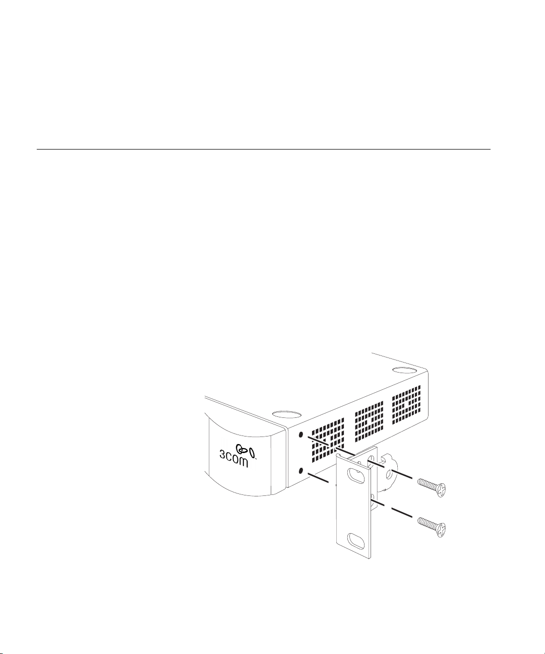
The Firewall is 1U high and will fit a standard 19-inch rack.
Figure 3
Fitting the Rack Mounting Bracket
Page 29
Firewall Front Panel 29
CAUTION: Disconnect all cables from the unit before continuing.
Remove the self-adhesive pads from the underside of unit, if already
fitted.
1 Place the unit the right way up on a hard, flat surface with the front
facing towards you.
2 Locate a mounting bracket over the mounting holes on one side of the
unit (refer to Figure 3).
3 Insert the two screws supplied in the mounting kit and fully tighten with
a suitable screwdriver.
4 Repeat the steps 2 and 3 for the other side of the unit.
5 Insert the unit into the 19-inch rack and secure with suitable screws (not
provided).
6 Reconnect all cables.
Securing the Firewall
with the Rubber Feet
Firewall Front Panel
LAN
1
The four self-adhesive rubber feet prevent the Firewall from moving
around on the desk. Only stick the feet to the marked areas at each
corner of the underside of the unit if you intend to place the unit directly
on top of the desk.
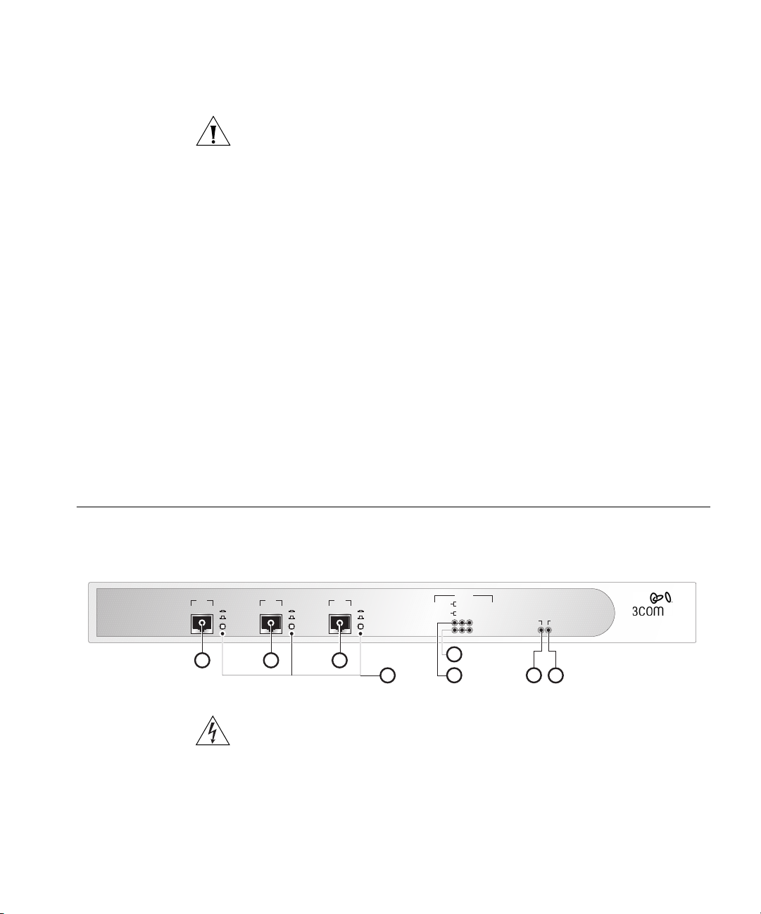
Figure 4 shows the front panel of the Firewall.
Firewall Front Panel
Uplink
Normal
2
WAN
Power/Self Test
8
Firewall
3CR16110-95
SuperStack 3
®
Status
green = full duplex
Packet
Uplink
Normal
3
4
Status
yellow = half duplex
green = 100 Mbps
yellow = 10 Mbps
5
6
Packet LAN/DMZ/WAN
Status LAN/DMZ/WAN
Alert
7
Uplink
Normal
Figure 4
DMZ
WARNING: RJ-45 Ports. These are shielded RJ-45 data sockets. They
cannot be used as standard traditional telephone sockets, or to connect
the unit to a traditional PBX or public telephone network. Only connect
RJ-45 data connectors, network telephony systems, or network
telephones to these sockets.
Either shielded or unshielded data cables with shielded or unshielded
jacks can be connected to these data sockets.
Page 30

30 C
HAPTER
2: I
NSTALLING THEHARDWARE
The Firewall front panel contains the following components:
1LANPort- Use a Category 5 cable with RJ-45 connectors. Connect this
port to any workstation or network device that has a 10BASE-T or
100BASE-TX port.
2DMZPort- Use a Category 5 cable with RJ-45 connectors. Use this port
to connect the Firewall to any workstation, server, or network device that
has a 10BASE-T or 100BASE-TX port.
3WANPort- Use a Category 5 cable with RJ-45 connectors. Connect this
port to any Internet access device that has a 10BASE-T or 100BASE-TX
port.
4 Normal/Uplink Switches - The setting of these switches determines the
operation of each port. See “Attaching the Firewall to the Network” on
page 32 for more information about setting these switches.
5StatusLEDs- The WAN, LAN, and DMZ ports each have a Status LED
that indicates the following:
■
Green indicates that the link between port and the next network
device is operational at 100 Mbps.
■
Yellow indicates that the link between the port and the next network
device is operational at 10 Mbps.
■
Off indicates that nothing is operational or that the link to the port
has failed.
6 Packet LEDs - The WAN, LAN, and DMZ ports each have a Packet LED
that indicates the following:
■
Green indicates that data is being transmitted/received on this port in
full-duplex mode.
■
Yellow indicates that data is being transmitted/received on this port in
half-duplex mode.
■
Off indicates that no traffic is being passed.
7AlertLED- This LED shows orange to alert you of the following:
A failure in the self-test the Firewall runs when switched on.
■
No operational firmware is currently loaded.
■
Potential attacks on your network.
■
An attempt to access a restricted site.
■
A hacker attack or access to a restricted service.
■
Page 31

Firewall Rear Panel 31
To diagnose faults see “Troubleshooting Guide” on page 167.
8 Power/SelfTestLED- This LED shows green to indicate that the unit is
switched on. This LED flashes for about 90 seconds while self-test is
running, and also when restarting.
If you have installed a 3Com RPS unit with the Firewall and the RPS has a
fault, the Power LED will flash to warn you. Once the fault on the RPS has
been rectified, the Power LED will stop flashing.
Firewall Rear Panel
9
Redundant Power System (RPS)
Figure 5 shows the rear panel of the Firewall.
Figure 5
10
Firewall Rear Panel
11
The Firewall rear panel contains the following components:
9 Power socket - Only use the power cord supplied with the Firewall.
10 Redundant Power System socket - Use this connector to attach a
Redundant Power System to the Firewall.
11 Reset Switch (recessed) - Use to reset the Firewall.
CAUTION: Holding the Reset Switch when you power on the Firewall will
erase the operational firmware and return the device to factory default
settings. To reset the Firewall see “Restore Factory Defaults” on page 187.
The SuperStack 3 Advanced Redundant Power System (RPS) offers you
the flexibility to supply power to your SuperStack devices in the event of a
failure of an internal power supply. The System is a group of products
from which you choose the most suitable for your equipment and its
configuration. One RPS unit can supply up to eight SuperStack 3 units.
The RPS status is displayed in the Unit Status screen on the Web interface.
Use the following SuperStack 3 RPS with the Firewall:
Page 32

32 C
WNeb and
etwork Servers
Client PC
SuperStack 3
irewallF
10/100 Mbps
witchS
Router
S
LB
erver
oad alancer
Web achec
HAPTER
2: I
NSTALLING THEHARDWARE
SuperStack 3 - Advanced RPS (3C16071)
■
and 60W RPS Power Module - (3C16072)
■
Attaching the Firewall to the Network
Figure 6 illustrates one possible network configuration.
Figure 6
Network Connection Diagram Showing Sample Network
F
S
S
N
C
SLB
W
LAN DMZ WAN
Key:
R
F
SuperStack 3
irewallF
C
Web achec
S
Client PC
Never connect two ports on the Firewall to the same physical network.
For example, never connect the LAN and DMZ ports into the same device
10/100 Mbps
witchS
SLB
S
erver
LB
oad alancer
W
N
WNeb and
etwork Servers
as this bypasses all firewall functions.
R
Router
Page 33

Attaching the Firewall to the Network 33
To attach the Firewall to your network:
1 Connect the Ethernet port labeled WAN on the front of the Firewall to
the Ethernet port on the Internet access device.
Refer to the documentation for the Internet access device to find out the
configuration of its Ethernet port. If it has an MDIX (normal)
configuration, then you can use a standard Category 5 cable.
Make sure that the Uplink/Normal switch is in the Uplink position for a
standard CAT-5 cable. If you are connecting the WAN port to a hub or
switch with a crossover cable, or directly to a workstation with standard
cable, make sure the Uplink/Normal switch is in the Normal position.
2 Connect the Ethernet port labeled LAN to your LAN.
IfyouareconnectingtheLANporttoahuborswitchusingastandard
Category 5 UTP cable, make sure that the Uplink/Normal switch for the
LAN port is in the Uplink position. If you are connecting the LAN port to
a hub or switch with a crossover cable, or directly to a workstation with
standard cable, make sure the Uplink/Normal switch is in the Normal
position.
3 Connect the Ethernet port labeled DMZ to the public servers.
If you are installing the Firewall DMZ and want to protect the public
servers, such as Web and FTP servers, use the DMZ port. If you are
connecting the DMZ port directly to a server using standard Category 5
cable, make sure that the Uplink/Normal switch is in the Normal position.
If you are connecting the DMZ port to an Internet access device using
standard Category 5 cable, make sure that the Uplink/Normal switch is in
the Uplink position.
4 Turn on or restart the Internet access device.
5 Plug the Firewall into an AC power outlet, and then plug the power
supply output cable into the power adapter socket.
6 Wait for the Power LED to stop flashing.
The Firewall is designed to start up as soon as power is supplied to it.
Then it runs a series of self-diagnostics to check for proper operation.
During these diagnostics, which take about 90 seconds, the Power LED
flashes.
CAUTION: Do not switch the Firewall off and on quickly. After switching
it off, wait approximately five seconds before switching it on again.
7 Make sure that the Link LEDs are on for all ports that are connected. If
not, see Chapter 12 for troubleshooting information.
Page 34

34 C
HAPTER
2: I
NSTALLING THEHARDWARE
The Firewall is now attached to the network.
By default, no traffic that originates from the Internet is allowed onto the
LAN, and all communications from the LAN to the Internet are allowed.
That is, all inbound connections are blocked and all outbound
connections are allowed.
You can now configure the Firewall. See the following chapters for more
information:
Chapter 3 for a quick setup guide for the Firewall.
■
Chapters 4 to 8 for full information about all the configuration
■
options.
Chapter 11 for information about the Web Site Filter and Network
■
Access Policy Rules.
At frequent intervals, check the Firewall for the following:
The Alert LED is not continuously lit — if it is, there are problems on
■
your network.
The case vents are not obstructed.
■
The cabling is secure and is not pulled taut.
■
Page 35

Q
UICKSETUP FOR THEFIREWALL
3
This chapter contains the following:
■
Introduction
■
Setting up a Management Station
■
Configuring Basic Settings
■
Configuring WAN Settings
■
Configuring LAN Settings
■
Confirming Firewall Settings
Introduction The first time the Firewall is started it runs an Installation Wizard.The
Installation Wizard asks you questions about your network and
configures the Firewall so that it works in your network.
If you later move your Firewall to another network and want to use the
Installation Wizard to configure the Firewall you can activate the
Installation Wizard manually. To start the Installation Wizard manually,
click on the Tools menu, followed by the Configuration tab, then the
Wizard button.
The configuration process can be split into three steps
1 To access the Installation Wizard you must first configure a computer as a
Management Station.See“Setting up a Management Station” page 36
for details.
2 Launch a web browser on the Management Station and enter
http://192.168.1.254
3 Follow the instructions supplied by the Installation Wizard and answer the
questions it asks.
to browse the Firewall.
Page 36

36 C
HAPTER
3: Q
UICKSETUP FOR THEFIREWALL
The process followed by the Installation Wizard is described in the
following sections:
Configuring Basic Settings
■
Configuring WAN Settings
■
Configuring LAN Settings
■
Confirming Firewall Settings
■
Settingupa Management Station
The Firewall has the following default settings:
IP address — 192.168.1.254
■
Subnet mask — 255.255.255.0
■
To access the Installation Wizard you must configure a computer to be in
the same subnet. This computer will be referred to as a Management
Station.
Follow the steps below to configure a computer as a Management
Station:
1 Note the IP address and subnet mask of the Management Station. You
will need to return your Management Station to these settings when you
have finished using the Installation Wizard.
2 ChangetheIPaddresstoavaluewithintheFirewall’s default subnet. This
will be a value between
192.168.1.254
would be
3 Enter
192.168.1.20
http://192.168.1.254/
192.168.1.1
and
192.168.1.254
as this is already taken by the Firewall. A suitable address
if this is not already taken by another device.
(the Firewall’s default IP address) into the
but not
box at the top of the browser window. The Installation Wizard is
displayed on screen and will guide you through the configuration
described in the sections below.
Configuring Basic
Settings
4 Remember to change the IP address and subnet mask of you
Management Station back to their original values when you have finished
configuring the Firewall using the Installation Wizard.
When the Installation Wizard first starts it displays a welcome screen
shown in Figure 7 below.
Page 37

Configuring Basic Settings 37
Figure 7 Installation Wizard Startup Screen
Click the Next button to start configuring your Firewall using the
Installation Wizard. The Set Your Password screen will be displayed as
shown in Figure 8 below.
If you want to configure your Firewall manually, click the Cancel button.
You will then be returned to the Web interface. See “Configuring the
Firewall” starting on page 49 to configure the Firewall using the Web
interface.
Setting the Password
Choose an administration password end enter it in the New Password
and Confirm New Password fields. This will be use in conjunction with the
admin
User Name when logging on to the Firewall in the future.
Page 38

38 C
HAPTER
3: Q
UICKSETUP FOR THEFIREWALL
Figure 8 Set Password Screen
Click the Next button to continue.
Setting the Time
Zone
Select the Time Zone appropriate to your location and click the Next
button to continue. The Time Zone you choose will affect the time
recorded in the logs.
Figure 9 Set Time Zone screen
This completes the Basic setup of the Firewall.
The Firewall will now attempt to configure some of its network settings
automatically. If it is unable to detect the settings automatically the
Page 39

Configuring WAN Settings 39
Installation Wizard will prompt you for the required settings.
Configuring WAN Settings
Automatic WAN
Settings
The Installation Wizard detects if the Firewall has been automatically
allocated an address for its WAN port.
■
If the Firewall has been allocated an IP address then it will attempt to configure itself automatically. See “Automatic WAN Settings” below.
■
If the Firewall has not been allocated an IP address then it will prompt
you for the settings it requires. See “Manual WAN Settings” on
page 40.
The Installation Wizard checks for the presence of a DHCP Server or a
PPPoEserverontheWANport.Dependingontheserverfoundthe
Firewall configures itself appropriately as described below:
■
DHCP Server — The Firewall requests an IP address form the DHCP
server on the WAN Port and uses the IP address, subnet mask and any
DNS information supplied
■
PPPoE Server — The Installation Wizard prompts you to enter the User
Name and Password supplied by your ISP. See Figure 10 below.
Figure 10
Configuring the Firewall’s PPPoE settings
If the WAN Setup has completed successfully, go to “Configuring LAN
Settings” on page 44.
Page 40

40 C
HAPTER
3: Q
UICKSETUP FOR THEFIREWALL
Manual WAN
Settings
If the Installation Wizard is unable to detect an automatic address server
on the WAN Port or if the WAN port is not connected it will display a
dialog box informing you of this and offer the choice of:
Connecting your Firewall (if not already connected) and restarting the
■
Installation Wizard.
Configuring your Firewall manually.
■
If you want to try to configure your Firewall again using the Installation
Wizard’s automatic detection then:
1 Disconnect the power cord from the Firewall.
2 Wait at least 5 seconds.
3 Reconnect the power cord.
4 Point your browser at the Firewall.
5 Follow the instructions supplied by the Installation Wizard.
If you want to configure the WAN settings of the Firewall manually then
click the Next button to continue.
The Installation Wizard will display its Connecting to the Internet screen,
shown in Figure 11 below. This allows you to specify the addressing
mode you are using on your WAN port.
Figure 11
Specifying the connection on the WAN port
The options are as follows:
Page 41

Configuring WAN Settings 41
■
Using a Single Static IP Address — This address must be taken by the Firewall’s WAN port to allow devices connected to the LAN port to communicate with devices connected to the WAN port. Network Address Translation (NAT) will be enabled.
■
Using Multiple Static IP Addresses — One address will be taken by
Firewall’s WAN port. NAT can be disabled sharing the addresses
between the DMZ port and the LAN port or enabled leaving all the
public addresses for the DMZ port. This option will be offered later in
the Installation Wizard.
■
UsinganIPAddressprovidedbyaPPPoEServer— OneIPaddressis
provided by the PPPoE server. This is taken by the WAN port. Network
Address Translation (NAT) will be enabled.
■
Using a Static IP address provided by a DHCP Server — One IP address
is provided by the DHCP server. This is taken by the WAN port.
Network Address Translation (NAT) will be enabled.
The settings for each of these options are detailed in the following
sections.
Using a Single Static
IP Address
Select the Assigned you a single static IP address option and click the Next
button. The Getting to the Internet screen will be displayed as shown in
Figure 12 below.
Figure 12
Configuring the Firewall
Page 42

42 C
HAPTER
3: Q
UICKSETUP FOR THEFIREWALL
To configure the WAN networking of your Firewall enter the following
1 In the Firewall WAN IP Address field enter the single address which has
been allocated to your Firewall. Enter the subnet mask for the above IP
address in the WAN/DMZ Subnet Mask field.
2 In the WAN Gateway (Router) Address field enter the address of your
internet access device. This may be a router, LAN modem or other device
and must be in the same subnet as the WAN IP address of the Firewall.
3 Enter any DNS servers external to your network in the order that you
want them to be accessed. The second server will only be accessed if the
first is unavailable or is unable to answer your query.
4 Click the Next button to proceed to the final part of the configuration.
See “Configuring LAN Settings” on page 44.
Using Multiple Static
IP Addresses
Select the Assigned you two or more IP addresses option and click the
Next button. The Network Address Translation screen will be displayed as
shown in Figure 13 below.
Figure 13
Choosing whether to activate NAT for multiple addresses
You are given a choice of:
Don’tuseNAT— This will disable Network Address Translation,
■
limiting you to the same number of IP devices as you have addresses.
Use NAT — This will enable Network Address Translation allowing you
■
to use as many IP devices as you wish on the LAN port. The remaining
public IP addresses can be allocated to devices on the DMZ port.
Page 43

Configuring WAN Settings 43
Click the Next buttontoproceedtotheGetting to the Internet screen
showninFigure14below.
Figure 14 Setting the Firewall WAN configuration
The Getting to the Internet screen contains the following fields:
1
Firewall WAN IP Address — Choose one of the addresses allocated by
your ISP as the address of the Firewall’s WAN port. This is used for
communication across the Firewall and to manage the Firewall remotely.
2
WAN/DMZ Subnet Mask — Enter the subnet mask that defines the IP
address range supplied by your ISP.
3
WAN Gateway (Router) Address — Enter the IP address of your route or
internet access device. This must be in the same address range as the
WAN IP Address.
4
DNS Server Address — Enter the IP address of your ISP’s DNS server in this
field. This will be used to resolve machine names to IP addresses. If you
have access to additional DNS Servers, enter them in the Optional Second
DNS Server Address and Optional Third DNS Server Address fields. These
will be accesses if the first stated DNS server does not respond or if it has
no record of a device name.
Click the Next button to proceed to the final part of the configuration.
See “Configuring LAN Settings” on page 44.
Page 44

44 C
HAPTER
3: Q
UICKSETUP FOR THEFIREWALL
UsinganIPAddress
provided by a PPPoE
Server
Select the Provided you with two or more IP addresses option and click
the Next button. The Firewall’s ISP Settings (PPPoE) screen will be
displayed as shown in Figure 15 below.
Figure 15
Configuring the Firewall’s PPPoE settings
Enter the User Name and Password as supplied by your ISP and click the
Next button to proceed to the final part of the configuration. See
“Configuring LAN Settings” on page 44.
Using a Static IP
address provided by a
DHCP Server
Configuring LAN Settings
Automatic LAN
Settings
Select the Automatically assigns you a dynamic IP address (DHCP) option
and click the Next button. If a DHCP server is detected the Firewall will
obtain its IP address automatically and will enable NAT for all devices
connected to the LAN port. Click the Next button again to confirm your
choice and proceed to the final part of the configuration. See
“Configuring LAN Settings” below.
Once the WAN setting of the Firewall have been configured, the
Installation Wizard configures the Firewall’s LAN settings. Some of the
following processes are optional and screens will only appear if they are
relevant to the configuration of your Firewall.
The Installation Wizard checks for the presence of a DHCP server on the
LAN port.
Page 45

Configuring LAN Settings 45
■
If there is no DHCP server found on the network connected to the
LAN port then the Firewall’s DHCP server is activated allowing
automatic address configuration on your LAN.
■
If there is a DHCP server found on the network connected to the LAN
port then the Firewall deactivates its DHCP server. This prevents the
Firewall giving out addresses that will conflict with those allocated by
another server.
Entering information
about your LAN
If you are using NAT the Fill in information about your LAN screen will
appear as shown in Figure 16 below. If you are not using NAT this screen
will not appear as these settings will be the same as the WAN settings.
Figure 16
■
Choose an IP address for the LAN port of your Firewall and enter it in
Configuring LAN Settings
the Firewall LAN IP Address field.
■
Enter the Subnet mask for your LAN network in the LAN Subnet Mask
field.
Configuring the DHCP
Server
The default IP address of the Firewall is
mask of
255.255.255.0
. You may want to keep this setting as other
192.168.1.254
with a subnet
3Com products also have their default addresses in this range.
Click the Next button to continue.
If a DHCP server has been detected on your LAN network then the
Firewall will disable its DHCP server and this screen will not display.
Page 46

46 C
HAPTER
3: Q
UICKSETUP FOR THEFIREWALL
Otherwise the Firewall’s DHCP Server screen will be displayed as shown in
Figure 17 below.
Figure 17 Configuring the Firewall’s DHCP Server
If you want to use the Firewall as a DHCP server to automatically provide
IP addresses for the computers on your LAN click the enable DHCP server
box and set the range of addresses you want it to allocate.
Confirming Firewall Settings
The addresses you set must be contained entirely within your LAN subnet
and must be currently unused.
Click the Next button to continue. The Firewall will now review its
settings. See “Confirming Firewall Settings” below for details.
The Firewall prompts you to confirm the settings it has established
through automatic configuration as well as those entered manually. You
will be presented with a screen similar to Figure 18 below showing you
settings with which the Firewall has been configured.
Page 47

Confirming Firewall Settings 47
Figure 18 Firewall Configuration Summary
■
If you want to keep a hard copy of this page click the Print This Page
button.
■
To accept the settings click the Next button.
■
To change the configuration of the Firewall click the Back button.
■
If you want to configure the Firewall manually:
■
Click the Cancel button to lose the changes made by the
Installation Wizard or
■
Click the Next Button, continue to the end of the Installation
Wizard and make the changes once the Firewall has reset
If you click the Next button the following screen will display.
Page 48

48 C
HAPTER
3: Q
UICKSETUP FOR THEFIREWALL
Figure 19 Congratulations Page
Click the Restart button to complete the configuration of the Firewall
using the Installation Wizard.
The Firewall will take under a minute to restart during which time the
Power/Self test LED will flash. When the Power/Self test LED stops
flashing the Firewall is ready for use.
Page 49

II
C
ONFIGURING THE
Chapter 4 Basic Settings of the Firewall
Chapter 5 Setting up Web Filtering
Chapter 6 Using the Firewall Diagnostic Tools
Chapter 7 Setting a Policy
Chapter 8 Advanced Settings
Chapter 9 Configuring Virtual Private Network Services
Chapter 10 Configuring High Availability
F
IREWALL
Page 50

50
Page 51

4
B
ASICSETTINGS OF THEFIREWALL
Chapters 4 to 10 describe in detail, each of the management operations
available from the Firewall’s web interface. You can access these
operations using a Web browser.
Refer to Figure 20 below for menu structure details of the Web interface
of the Firewall.
Figure 20 Tree Diagram of the menu structure
General
Network
Filter
Log
Tools
Policy
Advanced
VPN
High Availability
Unit Status
Settings
Settings
View Log
Restart
Services
Proxy Relay
VPN Summary
Configure
Set Password
DMZ Address
Custom List
Log Settings
Configuration
Add Service
Intranet
VPN Configure
Set Time
DHCP Server
Filter Update
Reports
Upgrade
Policy Rules
Static Routes
RADIUS
DHCP Setup
Keywords
User Privileges
One-to-One NAT
Diagnostics
Consent
Management
The descriptions of these menu options are split into chapters as follows:
■
Chapter 4 — This chapter describes the functions available in the
General and Network menus of the Web interface. These functions
are used to configure the Firewall for your network and location and
are most frequently accessed when setting up or moving the Firewall
or reconfiguring it for another role.
■
Chapter 5 —“Setting up Web Filtering” describes the functions
available in the Filter menu of the Web interface. These functions
allow you to control the access your users have to information on the
Web.
■
Chapter 6 —“Using the Firewall Diagnostic Tools” describes the
functions available in the Log and Tools menus of the Web interface.
These functions allow you to monitor and manage your Firewall.
Page 52

52 C
HAPTER
4: B
ASICSETTINGS OF THEFIREWALL
Chapter 7 —“Setting a Policy” describes the functions available in
■
the Policy menu of the Web interface. These functions enable you to
control the traffic across your Firewall.
Chapter 8 —“Advanced Settings” describes the functions available in
■
the Advanced menu of the Web interface. These functions enable you
to configure your Firewall for different topologies of network and to
provide some of the functionality of a router within your network.
Chapter 9 —“Configuring Virtual Private Network Services” describes
■
the functions available in the VPN menu of the Web interface. These
functions enable you encrypt and authenticate external access to your
Firewall.
Chapter 10 —“Configuring High Availability” describes the functions
■
available in the High Availability menu of the Web interface. These
functions allow you to set up a second SuperStack 3 Firewall as a live
backup should your Firewall fail.
Examining the Unit Status
To display the Firewall Unit Status, click on the General button and click
on the tab labelled Unit Status. A window similar to the following
displays.
Figure 21
Unit Status Window
This window shows the following information for your Firewall:
Firewall Serial Number
■
MAC Address
■
Registration Code (once registered)
■
Page 53

Setting the Administrator Password 53
■
ROM Version
■
Firmware Version
■
Device Up-time in days, hours, minutes, and seconds
Problems appear in red text. For example, if the Internet router was not
contacted, or the default password was not changed, this would be
listed. Items listed in red require immediate, corrective action. General
operation status messages, such as enabled hacker attack protection,
filter list status, and log settings are listed in black text.
Setting the Administrator Password
From the General screen, select Set Password. A window similar to that in
Figure 22 displays. If you are setting the password for the first time, the
default password is “password”. Change the administrator password to
keep the Firewall secure.
Figure 22
Set Password Screen
1 In the Old Password box, type the old password.
2 In the New Password and Confirm New Password boxes type the new
password
3 Click Update to save the new password.
The password cannot be recovered if it is lost or forgotten.
CAUTION: If the password is lost, you must reset the Firewall. See
“Resetting the Firewall” on page 162.
Page 54

54 C
HAPTER
4: B
ASICSETTINGS OF THEFIREWALL
Setting the Inactivity
Timeout
The Administrator Inactivity Timeout Setting allows you to extend or
reduce the period of time before the administrator is automatically
logged out of the Web interface. The Firewall is pre-configured to logout
the administrator after 5 minutes of inactivity.
Setting the Time From the General screen, select Set Time. A window similar to that in
Figure 23 displays.
Figure 23
Set Time Window
Time Zone
Select your time zone from the drop-down list box at the top of the
screen. If you cannot find your time zone in the list, you should set this to
the one with the same offset from GMT as is used at your location.
Use NTP (Network Time Protocol) to set time automatically
Check this box to allow the Firewall to synchronize its time using an
Network Time Protocol (NTP) server every hour. For example, if you
started the Firewall at 2:30, the clock will synchronize every hour at the
half hour—3:30, 4:30 etc.
To set the time automatically you need a connection to the Internet.
3Com recommends that initially you set the time manually even if you
have selected this option.
See Manual Time Set below to set the time manually.
Page 55

Setting the Time 55
Automatically adjust clock for daylight savings changes
Check this box to enable the Firewall to adjust to Daylight Savings Time
automatically depending on the time zone you have chosen. This features
works with NTP on or off.
Display UTC (Universal Time) in logs instead of local time
Check this box to set the time on the Firewall to Universal Time
Co-ordinated (UTC) time. UTC is the standard time common to all places
in the world. It is also commonly referred to as Greenwich Mean Time or
World Time. Many ISPs require firewall logs to be recorded in UTC as
tracking hackers can be very difficult if reports of times are not consistent.
Manual Time Set
To set the time manually enter the date and time in the boxes at the
bottom of the screen. Set the time in 24-hour clock, and use four digits
to specify the year (for example, 2001).
Page 56

56 C
HAPTER
4: B
ASICSETTINGS OF THEFIREWALL
Changing the Basic Network Settings
Setting the Network
Addressing Mode
Click the Settings Ta b f r o m t h e Network Menu to display the Network
Settings window (see Figure 24 below).
Figure 24
Network Settings, Standard Window
The Network Addressing Mode drop-down list contains four modes:
Standard
Choose Standard if you have IP addresses allocated by your ISP for each
machine that requires access to the Internet. When you select Standard,
Network Address Translation (NAT) is disabled. All nodes on the LAN must
use a valid public IP address.
NAT Enabled
Choose NAT Enabled if you want to use a single IP address for accessing
the Internet, or if you do not have an IP address allocated by your ISP for
each machine that requires access to the Internet. NAT provides
anonymity to machines on the LAN by connecting the entire network to
the Internet using a single IP address. This is useful for two purposes:
Additional security is provided because all the addresses on the LAN
■
are invisible to the outside world.
In cases where a network uses invalid IP addresses or if addresses are
■
in short supply, NAT can be used to connect the LAN to the Internet
without changing the IP addresses of computers and other devices on
the LAN.
Remote authenticated access is not possible with NAT enabled.
Page 57

Changing the Basic Network Settings 57
When using IP addresses on a LAN which have not been assigned by an
Internet Service Provider, it is a good idea to use addresses from a special
address range allocated for this purpose. The following IP address ranges
can be used for private IP networks and do not get routed on the
Internet:
10.0.0.0 - 10.255.255.255
172.16.0.0 - 172.31.255.255
192.168.0.0 - 192.168.255.255
Select NAT Enabled from the Network Addressing Mode drop-down list if
the network uses private IP addresses or if addresses are in short supply.
NAT with DHCP Client
Choose NATwithDHCPClientif you obtain the Firewall WAN IP address
fromaremoteDHCPserver.
NAT with PPPoE Client
Choose NAT with PPPoE Client if your Internet connection for the Firewall
WAN IP Address is to be obtained from a remote PPPoE server.
Specifying the LAN
Settings
For the LAN settings, specify:
Firewall LAN IP Address.
This is the IP address that is given to the Internet Firewall and used to
access it for configuration and monitoring. Choose a unique IP address
from the LAN address range.
LAN Subnet Mask
This value is used to determine what subnet an IP address belongs to. An
IP address has two components, the network address and the host
address.
For example, consider the IP address
Class C subnet mask of
192.168.228.) represent the Class C network address, and the last
(
number (
17) identifies a particular host on this network.
255.255.255.0 is used, the first three numbers
192.168.228.17. Assuming a
The following setting will also be available if PPPoE is selected:
Page 58

58 C
HAPTER
4: B
ASICSETTINGS OF THEFIREWALL
Connect/Disconnect
Pressing the Connect button in the Network Addressing Mode Section
will initiate a PPPoE session. If all fields have been entered correctly, the
Firewall will connect to the Internet. You can terminate a PPPoE session
by pressing the Disconnect button.
Specifying the
WAN/DMZ Settings
For the WAN/DMZ settings, specify:
WAN Gateway (router) Address
The WAN gateway address, also called the default gateway, is the address
of the router that attaches the LAN to the Internet.
Firewall WAN IP Address
This value is automatically set to the LAN IP Address for the Firewall
unless PPPoE is selected. For PPPoE enter the value specified by your ISP.
WAN/DMZ Subnet Mask
This value is automatically set to the LAN Subnet Mask for the Firewall
unless PPPoE is selected. For PPPoE enter the value specified by your ISP.
If PPPoE is selected, you also have to set the following:
User Name
Enter the User Name for your PPPoE account in this section. This is
information given to you by your service provider upon initial installation
of your broadband service.
Password
Enter the Password for your PPPoE account in this section. This is
information given to you by your service provider upon initial installation
of your broadband service.
Gateway (Router) Address:
This address will be provided automatically by your service provider.
For more information about PPPoE refer to “Frequently Asked Questions
about PPPoE” in Chapter 12.
Page 59

Specifying DMZ Addresses 59
Specifying the DNS
Settings
Specifying DMZ Addresses
In the Other Settings section, specify the DNS Servers.UptothreeDNS
servers can be specified, although not all have to be used. The Firewall
uses these servers to look up the addresses of machines used to
download the Web Site Filter and for the built-in DNS Lookup tool.
Type the required values and click Update to save the changes. It is
necessary to restart the Firewall for these changes to take effect.
The Firewall provides security by preventing Internet users from accessing
machines inside the LAN. This security, however, also prevents users from
reaching servers intended for public access, such as a Web or e-mail
server, which are crucial for effective Internet use.
In order to allow such services, the Firewall comes with a special
Demilitarized Zone (DMZ) port which you use for setting up public
servers. The DMZ is located between the local network and the Internet.
Servers on the DMZ are publicly accessible, but they are protected from
attacks such as SYN Flooding and Ping of Death. Use of the DMZ port is
optional and you do not have to connect it.
3Com recommends that you use the DMZ port as an alternative to Public
LAN Servers or to putting these servers on the WAN port where they are
not protected and not accessible by users on the LAN unless intranet
features are enabled.
Page 60

60 C
HAPTER
4: B
ASICSETTINGS OF THEFIREWALL
Click Network, and then select the DMZ Addresses tab. A window similar
to that in Figure 25 displays.
Figure 25 DMZ Address Window
Type the addresses for the DMZ individually or as a range. Type an
individual address in the From Address box. To enter a range of addresses,
such as the IP addresses from
the starting address in the From Address box and the ending address in
the To A d dr e ss box.Youcanspecifyupto64addressranges.
199.168.23.50
to
199.168.23.100,
type
Settingupthe DHCP Server
Each of the servers on the DMZ needs a public IP address. Obtain these IP
addresses from your ISP. Usually, the ISP can also supply information on
setting up public Internet servers.
Click the Update button to save your changes.
To delete an address or range, select it in the Address Range list and click
Delete.
Network Address Translation (NAT) does not apply to servers on the DMZ.
Servers on the DMZ Port must therefore have addresses in the same
range as the WAN Port.
Dynamic Host Configuration Protocol (DHCP),isameansforcomputers
on a network to obtain their IP settings from a centralized server.
DHCP offers complete centralized management of IP client
configurations, including IP addresses, gateway address, and DNS
address.
Page 61

Setting up the DHCP Server 61
The Firewall can allocate up to 255 static or dynamic IP addresses. 3Com
recommends you use a dedicated DHCP server if more addresses are
required.
To set up the DHCP server on the Firewall click Network, and then select
the DHCP Server tab. A window similar to that in Figure 26 displays.
Figure 26 DHCP Setup Window
Global Options Enable DHCP Server
Click this check box to enable or disable the DHCP server. This is disabled
by default. Leave the DHCP server disabled if there already is a DHCP
server on the LAN or if manual addressing is used on the LAN computers.
Lease Time
This is the amount of time that the IP address is leased, or given to the
client machine before the DHCP server attempts to renew that address. If
the client still requires the use of the IP address, the DHCP Server grants
the client the use of that IP address for the same amount of time. If the
client no longer requires the IP address, the address is freed and returned
to the pool of available addresses to be used again. The default value is
60 minutes.
Client Default Gateway
Enter the IP address of the WAN router used by LAN clients to access the
Internet. If NAT is being used this will be the LAN IP address of the
Firewall.
Page 62

62 C
HAPTER
4: B
ASICSETTINGS OF THEFIREWALL
Subnet Mask
Enter the Subnet mask for your network. This value will be given out by
theDHCPserverandwillbeusedbyclientdevicestodeterminethe
extent of your network.
Domain Name
Type the registered domain name for the network in the Domain Name
box, for example:
this blank.
DNS Servers
A DNS Server translates human readable host names into the numeric IP
addresses used by computers to route information to the correct
machine. You can use multiple DNS servers to improve performance and
reliability. To specify these manually select the Specify Manually radio box
and type the IP address of the DNS Server(s) in these boxes.
Alternatively, if you are using NAT with DHCP client you can select the Set
DNS Servers by Internet Firewalls DHCP Client to have these fields set
automatically.
3com.com.
If you do not have a Domain Name leave
Dynamic Ranges WhenaclientmakesarequestforanIPaddress,theFirewall’sDHCP
server leases an address from the Dynamic Ranges.
Prior to offering an address from the Dynamic Range to a requesting
client, the Firewall first verifies that the address is not already in use by
another machine on the LAN.
To create a range of dynamic IP addresses to be assigned to requesting
clients, type the starting number in the Range Start box, the ending
address in the Range End box and then click Update.
Allow BootP clients to use range
Click this check box to have Dynamic BootP clients configured when they
boot. Dynamic BootP clients are BootP clients that do not have an IP
address assigned to their MAC address. They are similar to DHCP clients
with the exception that leases are not supported.
Page 63

Viewing the DHCP Server Status 63
Delete Range
To remove a range of addresses from the dynamic pool, select it from the
scrolling list of dynamic ranges, and click Delete Range.
Static Entries Static addresses are used by client machines that support BootP or those
which require a fixed IP address. For example, client machines running
Web or FTP servers require static addresses.
To create a static IP address to be assigned to a requesting client, type an
IP address and the Ethernet (MAC) address of the client machine in the
appropriate boxes and click Update.
Delete Static
To remove a static address, select it from the scrolling list of static
addresses and click Delete Static.
Viewing the DHCP Server Status
Click Network and then select the DHCP Server Status tab. A window
similartothatinFigure27displays.
Figure 27
DHCP Status Window
The scrolling window shows the details on the current bindings:
■
IP and MAC address of the bindings
■
Type of binding (Dynamic, Dynamic BootP, or Static BootP).
Page 64

64 C
HAPTER
4: B
ASICSETTINGS OF THEFIREWALL
Todeleteabinding,whichfreestheIPaddressintheDHCPserver,select
the binding from the list and then click Delete.
Using the Network Diagnostic Tools
Choosing a
Diagnostic Tool
The Firewall has several tools built in which can help you solve network
problems. Click Network, and then select the Diagnostics tab.
Figure 28
Diagnostics Window with Pull-down Menu
The drop-down box provides five diagnostic tools:
DNS Name Lookup
Domain Name Service (DNS) is an internet service which allows users to
enter an easily remembered host name, such as
www.3Com.com
, instead of
numerical IP addresses to access Internet resources. The Firewall has a
DNS Lookup tool that returns the numerical IP address of a host name.
1 Select DNSNameLookupfrom the Choose a diagnostic tool menu.
2 TypethehostnametolookupintheLook up the name box and click Go.
The Firewall then queries the DNS server and displays the result at the
bottom of the screen.
The IP address of at least one DNS Server must be present on the
Network Settings tab for the DNS Name Lookup feature to function.
Page 65

Using the Network Diagnostic Tools 65
Find Network Path
Use the Find Network Path tool to show on which port, LAN, WAN or
DMZ where appropriate, an IP host is located. This is helpful to determine
if the Firewall is properly configured. For example, if the Firewall thinks
that a machine known to be on the Internet is located on the LAN port,
then there is a problem with the configuration of the network or intranet
settings. Find Network Path also shows if the target node is behind a
router, and the Ethernet address of the target node or router. Find
Network Path also shows which router a node is using, which can help
isolate router configuration problems.
1 Select Find Network Path from the Choose a diagnostic tool menu.
2 Type the IP address of the device and click Go. The test takes a few
seconds to complete.
If the network path is incorrect, check the intranet, static route, and DMZ
settings.
Find Network Path requires an IP address. Use the Firewall’s DNS Name
Lookup tool to find the IP address of a host.
Ping
The Ping tool bounces a packet off a machine on the Internet back to the
sender. This test shows if the Firewall is able to contact the remote host. If
users on the LAN are having problems accessing services on the Internet,
try pinging the DNS server, or other machine at the ISP’s location. If this
test is successful, try pinging devices outside the ISP. This shows if the
problem lies with the ISP’s connection.
1 Select Ping from the Choose a diagnostic tool menu.
2 Type the IP address of the device being pinged and click Go.Thetest
takes a few seconds to complete.
Ping requires an IP address. Use the Firewall’s DNSNameLookuptool to
find the IP address of a host.
Packet Trace
Use the Packet Trace tool to track the status of a data packet or
communications stream as it moves from source to destination. This is a
useful tool to determine if a packet or communications stream is being
stopped at the Firewall, or is lost on the Internet.
Select Packet Trace from the Choose a diagnostic tool drop-down list.
Page 66

66 C
HAPTER
4: B
ASICSETTINGS OF THEFIREWALL
Packet Trace requires an IP address. Use the Firewall’s DNS Name Lookup
tool to find the IP address of a host.
1 Enter the IP address of the remote host in the Tr ac e o n I P a ddres s box,
and click Start.
2 Initiate an IP session with the remote host using an IP client, such as Web,
FTP, o r Te ln et.
Use the IP address in the TraceonIPaddressbox, not a host name, such
www.3Com.com.
as
3 Click Refresh to display the packet trace information.
4 Click Stop to terminate the packet trace, and Reset to clear the results.
Technical Support Report
The Tech Support Report generates a detailed report of the Firewall’s
configuration and status, and saves it to the local hard disk. You can then
e-mail this file to Technical Support to help assist with a problem.
1 Select Tech Support Report from the Choose a diagnostic tool menu.
2 Click Save Report to save the report as a text file to the local disk.
Page 67

5
S
ETTING UP
This chapter describes the commands and options available in the Filter
menu. The menu is broken up into five sections shown in the user
interface as tabs.
To access a command click on Filter on the left hand side of the screen
and then on the appropriate tab.
This following sections are covered in this chapter:
■
Changing the Filter Settings
■
Filtering Web Sites using a Custom List
■
Updating the Web Filter
■
Blocking Websites by using Keywords
■
Filtering by User Consent
W
EBFILTERING
Changing the Filter
Settings
See Chapter 11 for background information about web filtering.
Click Filter, and then select the Settings tab.
A window similar to that in Figure 29 displays.
Page 68

68 C
HAPTER
5: S
ETTING UPWEBFILTERING
Figure 29 Filter Settings Window
Content Filtering only applies to nodes on the LAN Port.
Select the options in the Settings window, described below, to tailor the
content filtering to meet the needs of your organization.
Restricting the Web
Features Available
The following is a list of the web features that you can control using the
Web Filter. To allow your network to access a category leave the checkbox
unchecked. To deny your network access to a category check the
checkbox corresponding to that category.
ActiveX
ActiveX is a programming language that is used to embed small
programs in Web pages. It is generally considered an insecure protocol to
allow into a network since it is possible for malicious programmers to
write controls that can delete files, compromise security, or cause other
damage.
Java
Java is also used to embed small programs, also called applets, in Web
pages. It is generally considered safer than ActiveX since it has more
thorough safety mechanisms. However, some administrators may choose
to filter out Java since there have been instances of bugs in these safety
mechanisms.
Page 69

Changing the Filter Settings 69
Cookies
Cookies are used by Web servers to track usage. Unfortunately, cookies
can be programmed not only to identify the visitor to the site, but also to
track that visitor's activities. Because they represent a potential loss of
privacy, some administrators may choose to block cookies.
Web Proxy
When a proxy server is located on the WAN it is possible for LAN users to
circumvent content filtering by pointing to this proxy server. This feature
disables access to proxy servers located on the WAN. It has no effect on
those located on the LAN.
Setting Blocking
Options
Specifying the
Categories to Filter
The following is a list of the two alternative blocking options:
Log and Block Access
When selected, the Firewall logs and blocks access to all sites on the Web
Site Filter, custom, and keyword lists.
Log Only
When selected, the Firewall logs and then allows access to all sites on the
Web Site Filter, custom, and keyword lists. Use this function to monitor
inappropriate usage without restricting access.
The Web Site Filter can control access from the LAN to thousands of Web
sites that might be deemed inappropriate for your organization. Twelve
selectable Web site categories are provided so Internet access can be
tailored to the needs of the organization. Check the boxes for those
categories you wish to block. See “Introducing the Web Site Filter” on
page 153 for a detailed explanation.
■
Violence/Profanity
■
Partial Nudity
■
Full Nudity
■
Sexual Acts
■
Gross Depictions
■
Intolerance
■
Satanic/Cult
Page 70

70 C
HAPTER
5: S
ETTING UPWEBFILTERING
■
■
■
■
■
Drugs/Drug Culture
Militant/Extremist
Sex Education
Questionable/Illegal & Gambling
Alcohol & Tobacco
Specifying When
Filtering Applies
http://www.cyberpatrol.com/cybernot
Visit
to check the listing of a
site or to submit a new site.
Use the Time of Day setting to define time periods during which Internet
filtering is enabled. For example, in a school, it might be useful to enable
Internet filtering during normal school hours to protect students, but to
disable it after hours to give teachers complete access to the Internet.
Similar policies could be enabled to allow employees complete access to
the Internet after normal business hours.
Time of Day restrictions only apply to the Web Site Filter, Custom Sites,
and Keywords. Consent and Restrict Web Features, such as ActiveX, Java,
cookies and Web Proxy, are not affected.
Always Block
When selected, Internet Filtering is always active and Time of Day
limitations are not enforced. This is enabled by default.
Block Between
When selected, Internet Filtering is only active during the time interval
and days specified.
Filtering Web Sites using a Custom List
Enter the time period, in 24-hour format, and the start and end day of
the week during which you want to enforce Internet Filtering.
This function allows you to block specific web sites, or restrict access to a
list of approved web sites. This is in addition to the Web Site Filter. and
overrides the more general Web Site Filter categories.
Click Filter,andthenselecttheCustom List tab. A window similar to that
in Figure 30 displays.
Page 71

Filtering Web Sites using a Custom List 71
Figure 30 Custom List Window
You can add or remove web sites from the Custom List. For example, if a
local radio station runs a contest on its Web site that is disrupting normal
classroom Internet use, a school’s Technology Coordinator can easily add
that site to the Forbidden Domains list.
Setting up Trusted
and Forbidden
Domains
Trusted Domains — To allow access to a Web site which has been blocked
by the Web Site Filter, type its host name, such as
www.ok-site.com,
into
the Trusted Domains box. Do not use the complete URL of the site, that
is, do not include
adding
shop.3com.com
3Com.com
http://
also allows
andsoforth.Upto256entriesaresupportedinthe
. All subdomains are allowed. For example,
www.3Com.com, my.support.3com.com,
Trusted Domains list. Click Update to send the update to the Firewall.
Forbidden Domains — To block a Web site which has not been blocked
by the Web Site Filter, type its host name, such as
www.bad-site.com
into
the Forbidden Domains box. Do not use the complete URL of the site,
that is, do not include
adding
my.support.bad-site.com, shop.bad-site.com
bad-site.com
http://
also blocks
. All subdomains are blocked. For example,
www.bad-site.com,
and so forth. Click the
Update button to save your changes.
To remove a site which was previously added, select its name in the list
box, and click Delete Domain to send the update to the Firewall.
The following list describes the remaining options on the Custom List tab:
Page 72

72 C
HAPTER
5: S
ETTING UPWEBFILTERING
Enable Filtering on Custom List
Use this to enable or disable the custom filtering without re-entering all
site names. You do not have to re-enter names when the Web Site Filter
is updated each week, as the custom list does not expire.
Disable all Web traffic except for Trusted Domains
Click the Disable Web traffic except for Trusted Domains check box to
allow Firewall Web access only to sites on the Trusted Domains list. With
careful screening, this can block almost all objectionable material.
Don’t block Java/ActiveX/Cookies to Trusted Domains
Click this check box to make the Firewall allow Java, ActiveX and cookies
from sites on the Trusted Domains list to the LAN. In certain cases, it may
be desirable to allow Java, ActiveX or cookies from sites that are known
and trusted.
Changing the
Message to display
when a site is blocked
When a user attempts to access a site that is blocked by the Web Site
Filter, a message is displayed on their screen. The default message is:
Web Site Blocked by 3Com SuperStack 3 Firewall
.
You can type any message, including embedded HTML, up to 255
characters long in this box.
For example, if you type the following:
Access to this site was denied because it appears to
violate this organization’s
<A HREF=http://www.your-domain.com/acceptable_use_policy.h
tm>Acceptable Use Policy</A>. Please contact the
<A HREF=”mailto:admin@your-domain.com”>Network
Administrator</A> if you feel this was in error.
The user will see the following displayed when they attempt to visit a
blocked site:
Access to this site was denied because it appears to
violate this organization’s Acceptable Use Policy. Please
contact the Network Administrator
error.
if you feel this was in
Where the underlined sections are links to your company’s acceptable use
policy and to the network administrator’s email address.
Page 73

Updating the Web Filter 73
Updating the Web Filter
Since content on the Internet is constantly changing, make sure you
update the Web Site Filter used by the Firewall on a regular basis. When
you subscribe to the Web Site Filter, you can specify that it is updated
automatically every week for one year.
It is important to note that host names, and not IP addresses, are used for
all Internet filtering functions two reasons:
■
Many blocked sites operate server pools, where many machines
service a single host name, making it impractical and difficult to add
and maintain the numerical addresses of every server in the pool.
■
Many sites included in the Web Site Filter regularly change the IP
address of the server to try to bypass the Web Site Filters. This makes
maintaining a current list subscription critical for effective content
filtering.
Click Filter, and then select the Filter Update tab at the top of the
window. A window similar to that in Figure 31 displays.
Figure 31
Filter Update Window
Checking the Web
Filter Status
This section shows the status of the Web Site Filter and the date it was
last downloaded. If the Web Site Filter has not been downloaded the
Firewall displays a warning message in red text.
Page 74

74 C
HAPTER
5: S
ETTING UPWEBFILTERING
Downloading an
Updated Filter List
Setting Actions if no
Filter List is Loaded
Download Now
Click this button to download and update the Web Site Filter
immediately. This process may take a couple of minutes, depending on
Internet traffic conditions and requires a valid subscription to the Web
Site Filter.
Automatic Download
Check this box to enable automatic, weekly updates to the Web Site
Filter.Also,selectthedayoftheweekandthetimeofthedayto
download the new list. A valid Web Site Filter subscription is required.
There are two radio buttons that determine what happens if the Filter List
expires or if a download of a Filter List fails:
Block traffic to all websites except for Trusted Domains
Select this option if only access to Trusted Domains should be available in
the event of the Filter List expiring or a download failing. See “Setting up
Trusted and Forbidden Domains” on page 71 for more information.
Allow traffic to all websites
Select this option to provide open access to the internet in the event of
the Filter List expiring or a download failing.
Since it is necessary to restart the Firewall once the download is
complete, which causes a momentary interruption of Internet access, it is
a good idea to download new lists when LAN access to the Internet is at
a minimum.
Click Update to save your changes.
Once loaded, the creation date of the current active list is displayed at the
top of the window.
Each download of the Web Site Filter expires 30 days after it is
downloaded. The Filter List may also be erased if the Firewall fails to
download a new list. If the Filter List expires or is erased, the Firewall may
be configured to block all Web Sites except for Trusted Domains, or to
allow access to all Web Sites.
Page 75

Blocking Websites by using Keywords 75
Blocking Websites by using Keywords
Click Filter and then select the Keywords tab. A window similar to that in
Figure 32 displays.
Figure 32
Keywords Window
You can block Web URLs that contain specified keywords. This functions
as a second line of defense against objectionable material. For example, if
XXX
you specify the keyword
http://www.new-site.com/xxx.html
, the following URL:
is blocked, even if it is not included in the Web Site Filter.
Filtering by User Consent
It is important to use caution when enabling this feature. For example,
blocking the word breast may stop access to sites on breast cancer as well
as objectionable or pornographic sites.
To enable this function check the Enable Keyword Blocking check box
and click Update.
To add a keyword, in the Add Keyword box, type the keyword to block
and click Update.
To remove a keyword, select it from the list and click Delete Keyword.
Use the Consent tab on the Filter menu to specify which computers are
always filtered and which are filtered only when such protection is
requested by the user. You can also configure Consent to require users to
Page 76

76 C
HAPTER
5: S
ETTING UPWEBFILTERING
agree to the terms outlined in an organization’s Acceptable Use Policy
beforeyouallowthemtobrowsetheWebanyfurther.
Click Filter, and then select the Consent tab. A window similar to that in
Figure 33 displays.
Configuring User Consent Settings
Figure 33
Consent Window
Require Consent
Check this box to enable the consent features.
Maximum web usage is
In an environment where there are more users than computers, such as a
classroom or library, time limits are often imposed. You can set up the
Firewall to remind users when their time has expired by displaying the
page defined in the Consent page URL box. Type the time limit, in
minutes, in the Maximum web usage is box. Specify the default value of
zero (0) to disable this feature.
User idle timeout
After a period of inactivity, the Firewall requires the user to agree to the
terms outlined in the Consent tab before it allows any additional Web
browsing. To configure the value, follow the link to the User Privileges
window and type the desired value in the Privileged User Idle Timeout
box.
Page 77

Filtering by User Consent 77
Consent page URL (Optional Filtering)
When users begins an Internet session on a computer that is not always
filtered, they are shown a consent page and given the option to access
the Internet with or without filtering.
Create this page in HTML. It may contain the text from, or links to your
company’s Acceptable Use Policy (AUP).
You must include in this page links to two pages contained in the Firewall
which, when selected, tell the Firewall if the user wishes to have filtering
enabled or disabled. The link for unfiltered access must be:
192.168.1.254/iAccept.html
The link for filtered access must be:
192.168.1.254/iAcceptFilter.html
If you have changed the IP address or the Firewall use the IP Address of
the Firewall instead of
192.168.1.254.
Both the link for filtered access and the link for unfiltered access are case
sensitive.
Mandatory Filtered IP
addresses
Enter the URL of the page you have created in the When entering these
addresses you should not enter http:// before the address.
“Consent Accepted” URL (Filtering Off)
When users accept the terms outlined in the Consent page and choose to
access the Internet without the protection of filtering, they are shown a
page to confirm their selection. Type the URL of this page in the “Consent
Accepted” URL (Filtering Off) box.
“Consent Accepted” URL (Filtering On)
When users accept the terms outlined in the Consent page and choose to
access the Internet with the protection of filtering, they are shown a page
to confirm their selection. Type the URL of this page in the “Consent
Accepted” URL (Filtering On) box.
When users begin an Internet session on a computer where filtering is
mandatory, as described below, they are shown a consent page.You
Page 78

78 C
HAPTER
5: S
ETTING UPWEBFILTERING
create this page, and can add the text from the Acceptable Use Policy,
and notification that violations of the AUP are blocked and logged.
Consent Page URL (Mandatory Filtering)
When users access a page that you include in the list of Mandatory
Filtered IP Addresses the user is shown a page to inform them that the
page is Filtered. Type the URL of this page in the Consent page URL
(Mandatory Filtering field.
You must include a link in this page to:
192.168.1.254/iAcceptFilter.html
If you have changed the IP address or the Firewall use the IP Address of
the Firewall instead of
Click the Update button to save your changes.
The link for filtered access is case sensitive.
Add New Address
192.168.1.254.
You can configure the Firewall to provide filtering always for certain
computers on the LAN. Type the IP addresses of these computers in the
Add New Address box and click Submit. You can add up to 128 IP
addresses. To remove a computer from the list of computers to be
filtered, highlight the IP address in the list and click Delete Address.
To filter individual users by IP address you must use static IP addressing.
Page 79

6
U
SING THEFIREWALL
T
OOLS
This chapter describes the commands and options available in the Log
menu and the To ol s menu. Each menu is broken up into sections shown
in the user interface as tabs.
To access a command click on either Log or Too l s on the left hand side of
the screen and then on the appropriate tab.
This following sections are covered in this chapter:
■
Logs and Alerts
■
Viewing the Log
■
Changing Log and Alert Settings
■
Generating Reports
■
Restarting the Firewall
D
IAGNOSTIC
■
Managing the Firewall Configuration File
■
Upgrading the Firewall Firmware
Logs and Alerts The Firewall maintains an event log, which contains events that may be
security concerns. You can view this log with a browser using the Firewall
Web interface or you can set up a tab-delimited text file to be sent
automatically and periodically to any e-mail address for convenience and
archival purposes.
If you want to be alerted of high-priority information, such as an attack
on a server, you can specify that this information is immediately e-mailed,
either to the main e-mail address used by the log, or to a different
address, such as a paging service.
Page 80

80 C
HAPTER
6: U
SING THEFIREWALLDIAGNOSTICTOOLS
The Firewall logs the following events:
Unauthorized connection attempts
■
Blocked Web, FTP and Gopher sites, and blocked NNTP Newsgroups
■
Blocked ActiveX and Java
■
Blocked Cookies and Proxy attempts
■
Attacks such as IP spoofing, Ping of Death, SYN flood
■
Administrator logins
■
Successful/unsuccessful loading of the Web Site Filter
■
Viewing the Log To view the log click Log and then select the View Log tab. A window
similartothatinFigure34displays.
Figure 34
View Log Window
The log is usually displayed as a list in a table, but may appear differently
depending on the browser used. You may have to adjust the browser’s
font size and other viewing characteristics to display the log data most
efficiently. Depending on the browser, you can copy entries from the log
and paste them into documents. Alternatively, use the E-mail Log
function and review the log with an e-mail client rather than with a Web
browser.
Each log entry contains the date and time of the event, and a brief
message describing the event. Some entries contain additional
Page 81

Viewing the Log 81
information. Much of this information refers to the Internet traffic
passing through the Firewall.
TCP, UDP, or ICMP packets dropped
These log messages describe all traffic blocked from the Internet to the
LAN. The source and destination IP addresses of the packet is shown. If
the packet was TCP or UDP, the port number, in parentheses, follows
each address. If the packet was ICMP, the number in parentheses is the
ICMP code. The address information is usually preceded by the name of
the service described by either the TCP or UDP port, or the ICMP type in
quotation marks.
Web, FTP, Gopher, or Newsgroup blocked
The LAN IP and Ethernet addresses of a machine that attempted to
connect to the blocked site or newsgroup is displayed. In most cases, the
name of the site which was blocked will also be shown. In addition, there
is a box labeled Rule which contains one or more lowercase letters. These
correspond to the categories in the Web Site Filter as follows:
a = Violence/profanity
b = Partial nudity
c = Full nudity
d = Sexual acts
e=Grossdepictions
f = Intolerance
g=Satanic/cult
h=Drugculture
i = Militant/extremist
j = Sex education
k = Gambling/illegal
l = Alcohol/tobacco
See Chapter 11 for more information about these categories.
ActiveX, Java, or Code Archive blocked
The IP addresses of the source machine and the destination server is
shown.
Page 82

82 C
HAPTER
6: U
SING THEFIREWALLDIAGNOSTICTOOLS
When ActiveX or Java code is compressed into an archive it is not always
possible to differentiate between the two. If either ActiveX or Java
blocking is enabled, all code archives are blocked.
Cookie blocked
The IP addresses of the local machine and the remote server are shown.
Ping of Death, IP Spoof, and SYN Flood Attacks
The IP address of the destination machine which may be under attack, as
well as the source address which appears in the packet are shown. In
these attacks, the source address shown is usually fake and usually
cannot be used to determine the source of the attack.
Varying conditions on the Internet can produce conditions which may
cause the appearance of an attack, even when no-one is deliberately
attacking one of the machines on the LAN or DMZ. This is particularly
true for SYN Flood attacks. If the log message calls the attack ”possible”,
or it only happens on an irregular basis, then there is probably no attack
in progress. If the log message calls the attack ”probable”, contact the ISP
to see if they can track down the source of the attack. In either case, the
LAN and DMZ are protected and you do not need to take further steps.
Changing Log and Alert Settings
Click Log andthenselecttheLog Settings tab. A window similar to that
in Figure 35 displays.
Figure 35
Log Settings Window
Page 83

Changing Log and Alert Settings 83
Sending the Log Use the Sending the Log feature to inform your administrator of the
performance of the Firewall and to make sure that the log file always has
space for new entries.
Mail Server
To enable sending log or alert messages via e-mail, you must specify the
numerical IP address or the name of your SMTP server. You can obtain this
information from the Internet Service Provider that you use to connect
the network to the Internet. If you leave this box blank, log and alert
messages are not sent via e-mail.
Send Log To
This is the e-mail address to which log files are sent and must be a fully
qualified address, for example,
username@3Com.com
. Once sent, the log
file is cleared from the Firewall’s memory. If you leave this box blank, log
messages are not sent by e-mail. You can configure the Firewall to check
on a weekly basis if new software is available for download. See
“Upgrading the Firewall Firmware” on page 92 for more information. If
there is a new software release, an e-mail notification is sent to this
address.
Send Alerts To
Alerts are events, such as an attack, which may warrant immediate
attention. When an event generates an alert, a message is immediately
sent to an e-mail account or e-mail pager. Enter the e-mail address, for
example,
username@3Com.com
, to which alert messages are sent in this
box. This may be a standard e-mail account or, quite often, a paging
service. If you leave this box blank, alert messages are not sent by e-mail.
Firewall Name
A unique name for the Firewall. Enter this ID to identify the Firewall when
logs and alerts are emailed to the Network Administrator. Use
alphanumeric characters for this field. The MAC address of the Firewall is
the default value.
Syslog Server
In addition to the standard screen log, the Firewall can write extremely
detailed event log information to an external Syslog server. Syslog is an
industry standard protocol used for capturing log information for devices
on a network. The Firewall’s Syslog captures all screen log activity, plus
Page 84

84 C
HAPTER
6: U
SING THEFIREWALLDIAGNOSTICTOOLS
every connection’s source and destination IP addresses, IP service, and
number of bytes transferred. To support Syslog, you must have an
external server running a Syslog daemon on UDP Port 514. Syslog is a
standard feature of UNIX.
Enter the Syslog server’s IP address in the Syslog Server box.
To download the free 3Com Syslog Server visit:
http://www.3com.com/ssfirewall
and click the Syslog Server link.
The Firewall supports WebTrends Firewall Suite for comprehensive
reporting of the firewall. To enable WebTrends reporting, click on the Log
button located at the left side of the browser window. Click on the tab
labelled Log Settings just underneath the 3Com banner. On the Log
Settings page, enter the IP address of the WebTrends server in the Syslog
Server field. Click the Update button on the right of the browser window
and restart the Firewall for changes to take effect.
Changing the Log
Automation Settings
E-mail Log Now
Immediately sends the log to the address in the Send Log To box and then
clears the log.
Clear Log Now
Deletes the contents of the log.
The Automation time set here determines when the Firewall queries the
3Com server for new firmware. To ease traffic on the network server, this
time is randomized.
Send Log
This pop-up menu is used to configure the frequency of log messages
being sent as e-mail: daily, weekly, or only when the log is full. If the
weekly or the daily option is selected, specify a time of day when the
e-mail is to be sent. If the weekly option is selected, then also specify
which day of the week the e-mail is to be sent. If the weekly or daily
option is selected and the log fills up, it is automatically e-mailed to the
Send Log To address and cleared.
Page 85

Changing Log and Alert Settings 85
When log overflows
In some cases, the log buffer may fill up, which can happen if there is a
problem with the mail server and the log cannot be successfully e-mailed.
By default the Firewall overwrites the log and discards its contents. As a
security measure, you can choose to shut down the Firewall, which
prevents any further traffic from traveling through without being logged.
To d o t h i s s e l e c t Shutdown Firewall.
Selecting the
Categories to Log
Click the appropriate check box to enable or disable the generation of
the following log message categories.
System Maintenance
When enabled, log messages showing general system maintenance
activity, such as administrator logins, automatic loading of Web Site
Filters, activation and restarting the Firewall, are generated. This is
enabled by default.
System Errors
When enabled, log messages showing problems with DNS, e-mail, and
automatic Web Site Filter loading are generated. This is enabled by
default.
Blocked Web Sites
When enabled, log messages showing Web sites, newsgroups, or other
services blocked by the Web Site Filter, by keyword, or for any other
reason are generated. This is enabled by default.
Blocked Java, ActiveX, and Cookies
When enabled, log messages showing Java, ActiveX, and Cookies which
are blocked by the Firewall are generated. This is enabled by default.
User Activity
When enabled, log messages showing any successful or unsuccessful user
logins will be generated. This is enabled by default.
Page 86

86 C
HAPTER
6: U
SING THEFIREWALLDIAGNOSTICTOOLS
Attacks
When enabled, log messages showing SYN Floods, Ping of Death, IP
Spoofing, and attempts to manage the Firewall from the Internet are
generated. This is enabled by default.
Dropped TCP
When enabled, log messages showing blocked incoming TCP
connections are generated. This is enabled by default.
Dropped UDP
When enabled, log messages showing blocked incoming UDP packets are
generated. This is enabled by default.
Dropped ICMP
When enabled, log messages showing blocked incoming ICMP packets
are generated. This is enabled by default.
Network Debug
When enabled, log messages showing Ethernet broadcasts, ARP
resolution problems, ICMP redirection problems, and NAT resolution
problems are generated. This category is intended for experienced
network administrators. This is disabled by default.
Alert Categories Alerts are events, such as an attack, which may warrant immediate
attention. When an event generates an alert, a message is immediately
sent to the e-mail account defined in the Send alerts to box on the Log
Settings window (see page 82).
Attacks
When enabled, all log entries that are categorized as an Attack are
generated as an alert message. This is enabled by default.
System Errors
When enabled, all log entries that are categorized as a System Error are
generated as an alert message. This is enabled by default.
Page 87

Generating Reports 87
Blocked Web Sites
When enabled, all log entries that are categorized as a Blocked Web Site
are generated as an alert message. This is disabled by default.
Click Update to save your changes.
Generating Reports
The Firewall can analyze the event log to show the following:
■
Top25mostaccessedWebsites
■
Top 25 users of bandwidth by IP address
■
Top 25 services that consume the most bandwidth
Click Log andthenselecttheReports tab. A window similar to that in
Figure 36 displays.
Figure 36
Reports Window
Collecting Report
Data
Start Data Collection
By default, the log analysis function is disabled. Click Start Data Collection
to begin log analysis. When log analysis is enabled, the button label
changes to Stop Data Collection.
Page 88

88 C
HAPTER
6: U
SING THEFIREWALLDIAGNOSTICTOOLS
Reset Data
Click Reset Data to clear the report statistics and begin a new sample
period. The sample period is also reset when data collection is stopped or
started, and when the Firewall is restarted.
Current Sample Period
Displays the current sample period shown in the reports.
Viewing Report Data Select the desired report from the Display Report popup menu. The
options are:
■
Web Site Hits
■
Bandwidth Usage by IP Address
■
Bandwidth Usage by Service.
These reports are explained as follows.
Web Site Hits
Selecting Web Site Hits from the Report to view drop-down list displays a
table showing the URL for the 25 most accessed Web sites and the
number of hits to that site during the current sample period.
Use the Web Site Hits report to ensure that the majority of Web access is
to sites considered applicable to the primary business function. If leisure,
sports, or other similar sites are on this list, it may signal the need to
change or more strictly enforce the organization’sAcceptableUsePolicy.
Bandwidth Usage by IP Address
Selecting Bandwidth Usage by IP Address from the Report to view
drop-down list displays a table showing the IP Address of the 25 top users
of Internet bandwidth and the number of megabytes transmitted during
the current sample period.
If using DHCP, remember that the IP address assigned to a computer can
change. You may have to check the DHCP server logs to correctly identify
which computer is listed in the report.
Bandwidth Usage by Service
Selecting Bandwidth Usage by Service from the Report to view
drop-down list displays a table showing the name of the 25 top Internet
Page 89

Restarting the Firewall 89
services, such as HTTP, FTP, RealAudio and so forth, and the number of
megabytes received from the service during the current sample period.
Use the Bandwidth Usage by Service report to make sure the Internet
services being used are appropriate for the organization. If services such
as video or push broadcasts are consuming a large portion of the
available bandwidth, it may signal the need to change or more strictly
enforce the organization’s Acceptable Use Policy.
Restarting the Firewall
To r es ta rt t h e F i r ew al l:
1 Click Tools and select the Restart tab. A window similar that in Figure 37
displays.
Figure 37
Restart Window
2 Click Restart SuperStack 3 Firewall.
3 Click Yes to confirm the restart and send the restart command to the
Firewall. The restart takes about 90 seconds, during which time the
Firewall cannot be reached from the Web browser and all network traffic
through it is halted.
If you have changed the IP settings of the Firewall, you must alter the IP
settings of the management station accordingly. You may have to restart
the management station, depending on its operating system, for the
change to take effect.
Page 90

90 C
HAPTER
6: U
SING THEFIREWALLDIAGNOSTICTOOLS
When the Front Panel Power LED stops flashing you can refresh your
browser.
To reset the Firewall clearing it of all settings see “Resetting the Firewall”
on page 162 for details.
Managing the Firewall Configuration File
The Configuration tool allows you to save and restore the configuration
settings of the Firewall. Click Tools andthenselecttheConfiguration tab.
A window similar to that in Figure 38 displays.
Figure 38
Configuration Window
Use the Configuration tab to specify where the settings for the Firewall
are saved to and retrieved from for backup purposes. You can also restore
the default settings from the Configuration tab. 3Com recommends that
you back up the Firewall settings.
Page 91

Managing the Firewall Configuration File 91
Importing the
Settings File
Use this function to import a previously saved settings file back into the
Firewall.
1 Click Import. A window similar to that in Figure 39 displays.
Figure 39
Import Window
2 Click Browse to find a file which was previously saved using Export.
YoumayneedtosetFiletypeto*.*tobeabletoseethe.expfileyou
exported.
3 Once you have selected the file, click Import.
4 Once the file transfer has completed the status at the bottom of the
screen will give you the option to Restart the Firewall.
5 Click Restart.
Make sure that the Web browser supports HTTP uploads. If it does not,
you cannot import the saved settings.
Note that this will not change the password for the unit.
Page 92

92 C
HAPTER
6: U
SING THEFIREWALLDIAGNOSTICTOOLS
Exporting the
Settings File
You can save the Firewall configuration settings to a file on a local system
andthenreloadthosesettings.
1 Click Export. A window similar to that in Figure 40 displays.
Figure 40
Export Window
2 Choose the location to save the settings file. This should be saved as
<Filename>.exp
.Thisdefaultsto
3com_firewall.exp
. The process may
take up to a minute.
The Administration password is not saved to the exported file in this
process.
Restoring Factory
Default Settings
Using the Installation
Wizard to reconfigure
the Firewall
Upgrading the Firewall Firmware
Click Restore to clear all configuration information and restore the
Firewall to its factory state.
Clicking Restore will not change the Firewall’s LAN IP Address, LAN
Subnet Mask, WAN Gateway Address and Password.
Click on the Wizard button to start the Installation Wizard. This allows
you to configure the Firewall for a new location or role. See Chapter 3,
“Quick Setup for the Firewall”.
The Upgrade tool allows you to upgrade the operational firmware of the
Firewall. The Firewall has flash memory and can be easily upgraded with
new firmware.
Page 93

Upgrading the Firewall Firmware 93
When upgrading the firmware, all settings will be reset to factory default.
3Com recommends that you export the Firewall’s configuration settings
before uploading new firmware and then import them again after the
upgrade has been completed.
The Firewall checks to see if new firmware is available for download on a
weekly basis. If there is a new firmware release, you can configure the
Firewall to send an e-mail notification to the address in the Send log to
box.
Click Tools andthenselecttheUpgrade tab. A window similar to that in
Figure 41 displays.
To be notified automatically when new firmware is available:
1 Click the Send me e-mail when new firmware is available check box.
2 Click Update.
To download new firmware go to
http://www.3com.com/ssfirewall
and follow the instructions.
Figure 41
Upgrade Window
To upload the new firmware onto the Firewall:
1 Click Upload Firmware Now.
A window similar to that in Figure 42 displays.
Page 94

94 C
HAPTER
6: U
SING THEFIREWALLDIAGNOSTICTOOLS
Figure 42 Save Settings Window
2
Click Yes if you have saved the settings.
A window similar to that in Figure 43 displays.
Figure 43 Firmware Upload Window
3
Click Browse... and select the firmware file you have downloaded from
the 3Com FTP site to a local hard drive or server on the LAN.
4
Click Upload to begin the upload.
Make sure that your Web browser supports HTTP uploads.
When uploading the firmware to an Firewall, it is important not to
interrupt the Web browser by closing the window, clicking a link, loading
a new page, or removing the power to the Firewall. If the Firewall is
Page 95

Upgrading the Firewall Firmware 95
interrupted this way, it may result in the Firewall not responding to
attempts to log in.
If your Firewall does not respond, see Chapter 12, “Troubleshooting
Guide”.
5 Restart the Firewall for the changes to take effect.
Page 96

96 C
HAPTER
6: U
SING THEFIREWALLDIAGNOSTICTOOLS
Page 97

7
S
ETTING A
This chapter describes the commands and options available in the Policy
menu. The menu is broken up into sections shown in the user interface as
tabs.
To access a command click on Policy on the left hand side of the screen
and then on the appropriate tab.
This following sections are covered in this chapter:
■
Changing Policy Services
■
Adding and Deleting Services
■
Editing Policy Rules
■
Updating User Privileges
■
Setting Management Method
P
OLICY
Changing Policy
Services
See Chapter 11 for background information about policies.
This section covers which network services are blocked by the Firewall
and which are allowed to pass through.
Page 98

98 C
HAPTER
7: S
ETTING APOLICY
Click Policy, and then select the Services tab. A window similar to that in
Figure 44 displays.
Amending Network
Policy Rules
Figure 44
Services Window
The Services window contains a table showing the defined Network
Policy Rules. At the bottom of the table is the Default rule which affects
all IP services. Any rules you create for a specific protocol override the
Default rulewithrespecttothatprotocol.
LAN Out Checkbox
When the check box is clicked for a specific protocol, users on the LAN
can access servers of that type on the Internet. When the check box is
cleared, users on the LAN cannot access servers of that type on the
Internet. The default value is enabled. When the Warning Icon is
displayed to the right of the check box, there is a Custom Rule in the
Rules tab section that modifies the behavior of the listed Network Access
Rule.
LAN In Checkbox
When this check box is cleared, access to the protocol is not permitted
from the WAN to the LAN and, if appropriate, from the DMZ to the LAN.
When the service is selected, users on the WAN and DMZ can access all
hosts on the LAN via that protocol. The default value is disabled; use
caution when enabling. When the Warning Icon isdisplayedtotheright
of the check box, there is a Custom Rule in the Rules tab section that
modifies the behavior of the listed Network Access Rule. The LAN In
column is not displayed if NAT is enabled.
Page 99

Changing Policy Services 99
DMZ In Checkbox
If you are using the DMZ port on the Firewall access to the protocol is not
permitted from the Internet to the DMZ when this check box is cleared.
When the service is selected, users on the Internet can access all hosts on
the DMZ via that protocol. The default value is enabled. When the
Warning Icon is displayed to the right of the check box, there is a Custom
Rule in the Rules tab section that modifies the behavior of the listed
Network Access Rule.
Public LAN Server Address
A Public LAN Server is a single host on the LAN that is defined to handle
all traffic originating from the Internet to the LAN of a specific protocol,
such as HTTP. Define a Public LAN Server by typing its IP address in the
Public LAN Server box for that protocol. If a server is not designated for a
certain protocol, type
0.0.0.0
in the box.
Changing NetBIOS
Broadcast Settings
Systems running Microsoft Windows Networking communicate with one
another through NetBIOS broadcast packets. By default, the Firewall
blocks these broadcasts. If you have Windows computers on more than
one port of the Firewall, for example if you are using the Firewall as an
internal security measure you may need to enable NetBios Broadcast
Passthrough.
From LAN to DMZ
To enable Windows machines connected to the LAN port to see other
Windows machines connected to the DMZ port in their Network
Neighborhood check this box.
Click the Update button to save your changes.
From LAN to WAN
To enable Windows machines connected to the LAN port to see other
Windows machines connected to the WAN port in their Network
Neighborhood check this box.
Click Update to save your changes.
NetBIOS passthrough only applies to connections made by using
Windows Networking. You will still be able to see web servers using the
Page 100

100 C
HAPTER
7: S
ETTING APOLICY
HTTP protocol even if both NetBIOS Passthrough boxes are left
unchecked.
Enabling Stealth
Mode
Allowing Fragmented
Packets
By default, the Firewall responds to incoming connection requests as
either blocked or open. If you check the box to enable Stealth Mode and
click on the Update button, no response will be made to inbound
requests, which makes your network invisible to potential attackers.
By default the Firewall drops fragmented packets as they may form part
of a Denial of Service attack. Fragmented packets can occur naturally as
part of a congested network and you may want to allow them to increase
the throughput of your Firewall.
Fragmented packets that are dropped will show as entries in the Firewall
Log. See “Viewing the Log” on page 80 for details.
Allow Fragmented Packets over PPTP/IPSec
Point-to-point Tunneling Protocol (PPTP) and IPSec are forms of VPN that
allows data to pass through the Firewall without termination. In some
cases, passing large amounts of data through the Firewall can cause
packets to become fragmented which results in low data throughput.
If fragmented PPTP packets are being blocked check the Over PPTP box. If
fragmented IPSec packets are being blocked check the Over IPSec box.
Setting the Network Connection Inactivity Timeout
If a connection to a server outside the LAN remains idle for more than 5
minutes (default value), the Firewall closes the connection. This is done
for security purposes. Without this timeout, it is possible that connections
could stay open indefinitely, creating potential security risks. You can
increase the timeout interval if users frequently complain of dropped
connections in applications such as Telnet and FTP.
Click Update to save your changes.
You must restart the Firewall for these changes to take effect.
 Loading...