

Page 1
1
Manual for: SU-2A Gas Burner
50,000 BTU/H to 250,000 BTU/H
The burner shall be used only with NATURAL GAS or LP GAS as specified on the nameplate.
Warning: If the following instructions are not followed exactly, a fire or
explosion may result, causing property damage, personal injury or death.
• Do not store or use gasoline or other flammable vapors and liquids in the vicinity
of this or any other appliance.
-
WHAT TO DO IF YOU SMELL GAS
• Do not try to light any appliance.
• Do not touch any electrical appliance.
• Do not use any phone in your building.
• Immediately call your gas supplier from a neighbor’s phone.
• Follow the gas supplier’s instructions.
•
If you cannot reach your gas supplier, call the fire department.
• A qualified installer, service agency or the gas supplier must perform installation and service.
• All installations must be made in accordance with all state and local codes, which may differ
from instructions in this manual.
• The installer should inform and demonstrate to the user the correct operation and maintenance
of the appliance.
• The installer shall also inform the user of hazards of flammable liquids and vapors and shall
remove such liquids and vapors from the vicinity of the burner.
• The installation adjustment data trap, or label supplied, shall be filled in and affixed to the
burner or the covered appliance.
These instructions should be affixed to the burner or adjacent to the heating appliance
NYC MEA # 382-03-E
–
Massachusetts Plumbing Board G1-0903-40:09/03/2004
Manufactured by Heat Wise, Inc.
1528 Rocky Point Road, Middle Island, NY 11953
rev 2004-2
Page 2
2
Chart 1: Natural Gas and LP
Length
Model
SU-2A
- Control System: Fenwal Model 2466H936-111 with 15 Second Pre-Purge and 60 Second Post-Purge OR
Honeywell S89F with 34 second Pre-Purge.
- The system uses a remote ignition system with a separate Ignition Transformer.
- Gas Valve: VR8205A 2008 or VR 8305 P with step opening (special applications).
of Flame
Tube
4 ¼”
Firing Rate Burner
Min
BTU/H
50,000 250,000
Max
BTU/H
Primary
Electric
Input
120 Volt
60 Hz
1 Ph
Secondary
Electric
Input
24 Volts
Total
Watts
150
Max
Total
Amps
3 or
less
Gas
Conn.
½”
BURNER DESCRIPTION
The SU-2A Gas Burner is a fully automatic, flame retention burner and is suitable for
combustion of natural gas or LP. Changing orifices alters the firing rate. The combustion air can
be adjusted for proper O2 or CO2 by the dial located on top of the burner housing, which allows the
air to flow more or flow less within the burner.
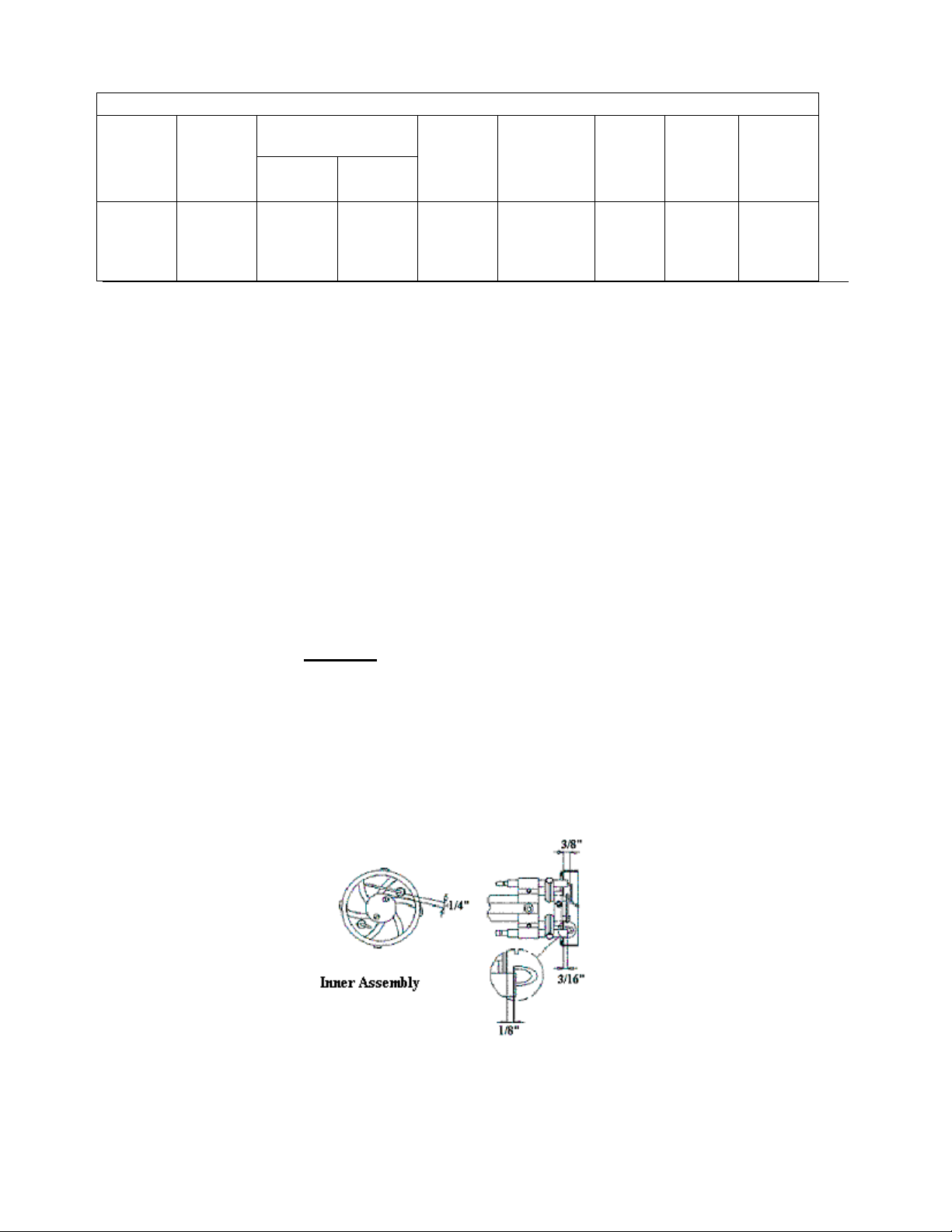
Two electrodes act as a sparker and a flame rod (See Fig. 1). Flame rectification by this
flame rod monitors the continued presence of the burner flame. With three trials for ignition
consistency (with Fenwal control), trouble free, safe operation is achieved.
control the appliance; 2) DO NOT shut off the control switch to the pump or blower
gas-burning appliance. The conversion must conform to local codes. In the absence of such
codes, the American National Standard for the Installations of gas conversion burners, ANSI
Z21.17-1984, Z21.8A-1990 and the National Fuel Gas Code ANSI 223.1-1992 or current
standards should be applied.
Warning: Should overheating occur, 1) shut off the manual gas shut off valve to
This power gas burner is designed to convert oil and/or coal fired boilers and furnaces to a
Fig. 1 Electrode and Flame Sensor Dimensions
Page 3
3
(
)
CONVERTING OIL TO GAS
Before attempting the gas conversion, check to insure the heating system is properly sized
for the total heating demand and the entire system is in good operating condition, including the fire
chamber and flue passages. It is important to allow adequate clearance around the appliance for
servicing and proper operation of the burner.
CONVERTING COAL TO GAS
When converting a coal appliance to gas, the coal firing chamber or the ash pit chamber
may be used as a gas firing chamber, provided the flame does not impinge on the walls of the
appliance (see Chart 2). It is important to allow adequate clearance around the appliance for
servicing and proper operation of the burner.
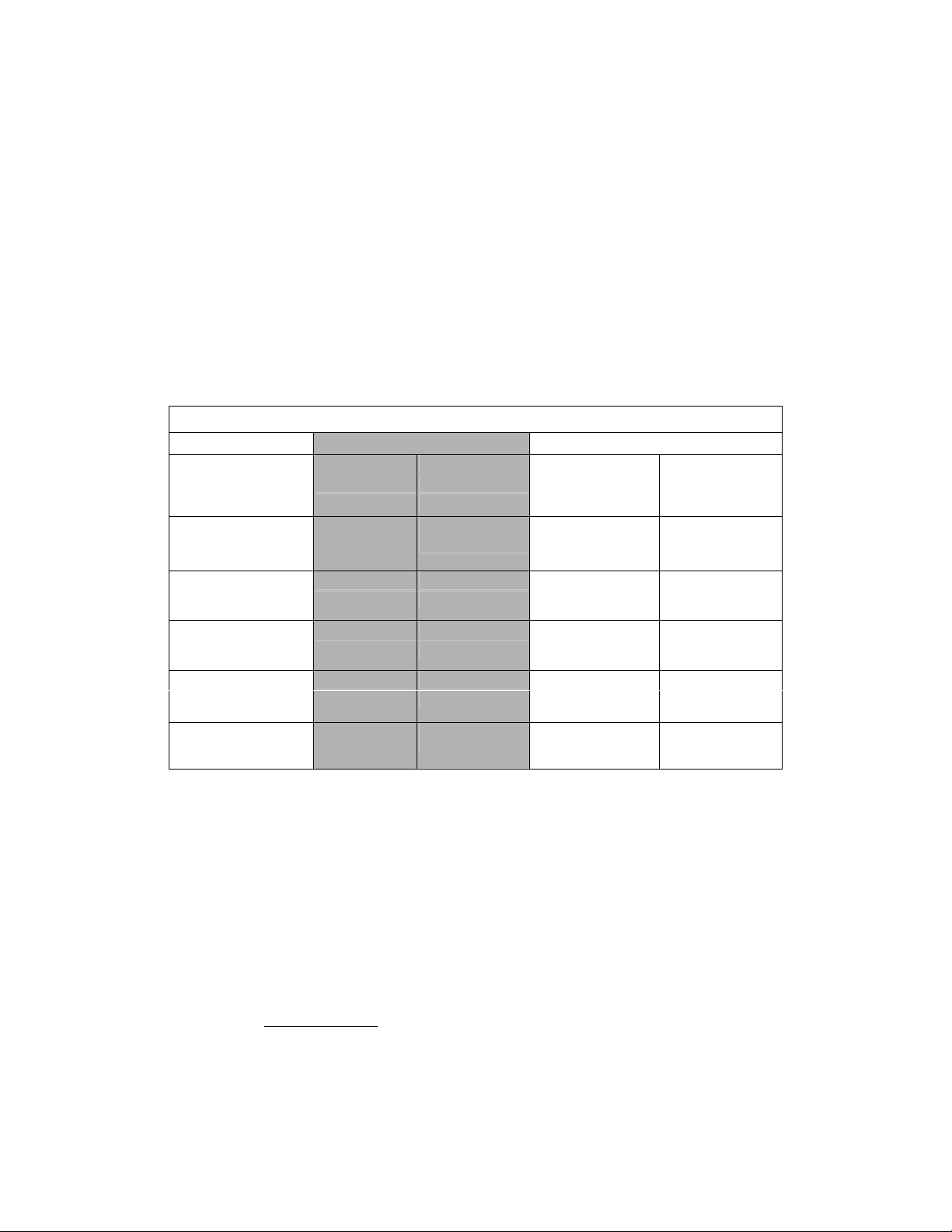
Input Rate
per hour Height
50,000 to
80,000 to
150,000 9" 8" 9" 8"
Chart 2: Minimum Firing Chamber Dimensions
BTU Length Width Diameter Minimum
80,000
Rectangular Round
6"
6"
6"
6"
150,000 to
180,000 11" 8" 11" 8"
180,000 to
200,000 14" 8" 14" 12"
200,000 to
250,000
15"
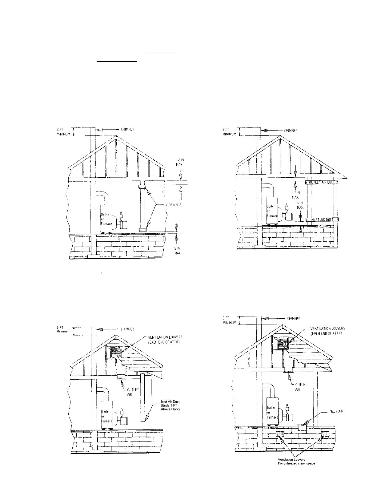
AIR FOR COMBUSTION
8"
15"
13"
If the boiler or furnace room is unusually tight, or if the house has a ventilation fan, it is
recommended that the combustion air be supplied to the furnace room through intakes from the
outside of the building. The intakes must terminate facing down in order to avoid obstruction from
rain, snow, leaves, etc. Openings must have one square inch of free area per 10,000 BTU input
rate (see Example 1). Follow the heat exchanger manufacturer's recommendations for installing
louvers, etc.
Example 1: 150,000 BTU/hr firing rate
2
1
150 000
, / *
( )
BTU hr
10000
, /
in
BTU hr
15
2
in=
Page 4
4
CHIMNEY REQUIREMENTS
The chimney should extend
2) and be free in a
cause a down draft. The chimney should be lined as required by the local Gas Company or local
codes.
Some utilities require new chimney liners for all gas installations. Use a corrosion resistant
chimney liner (approved for gas service) of the same size as the vent pipe.
radius of 30’
at least 3’
of objects such as tree limbs, other buildings, etc, which may
above a flat roof or the highest roof ridge (see Fig.
Fig. 2 Chimney and Fresh Air Dimensions
Page 5
5
tube from burning off. Slide the blast tube into the boiler to
20 setscrews. Seal
VENT PIPE AND DRAFT HOOD SIZES
Refer to Chart 3 to properly size the flue pipe. If the flue pipe exceeds 10’ in length
(including elbows), use the next larger diameter flue pipe and draft hood. If a draft regulator is
required, any Canadian Standards Association (CSA) or Underwriter’s Laboratory (UL) listed
double swing draft regulator must be used.
installations.
When the burner is used as a conversion burner, draft over fire should be maintained
A movable internal damper is not permitted on gas
as –0.02” W.C. by adjusting the regulator when the burner is fired. The installer should follow the
barometric draft regulator manufacturer’s instructions for complete details for installations and
adjustments. The vent pipe should extend only to (but not beyond) the inside wall of the chimney.
The sizing below does not apply on any factory listed packaged units.
Chart 3: Vent Pipe Sizing
Input per Hour
Up to 120,000 BTU
120,000 to 160,000 BTU
160,000 to 250,000 BTU
Draft Hood and Flue Pipe Sizes
5” diameter
6” diameter
7” diameter
INSTALLING THE BURNER
If the burner being installed is a conversion burner, use a prefabricated chamber or build a
firing chamber that can withstand 2000o F (See Chart 2 on page 3). Measure the boiler or furnace
mounting plate to determine the flame tube insertion required. Deduct ¼” from the total length
and tighten the flange on the flame tube with the deducted insertion depth. The ¼” deduction will
prevent the tip of the flame tube from burning off. Install the burner on the unit and then tighten
the nuts on the flange so that the burner is permanently secured. Seal off any free openings with
high temperature cement.
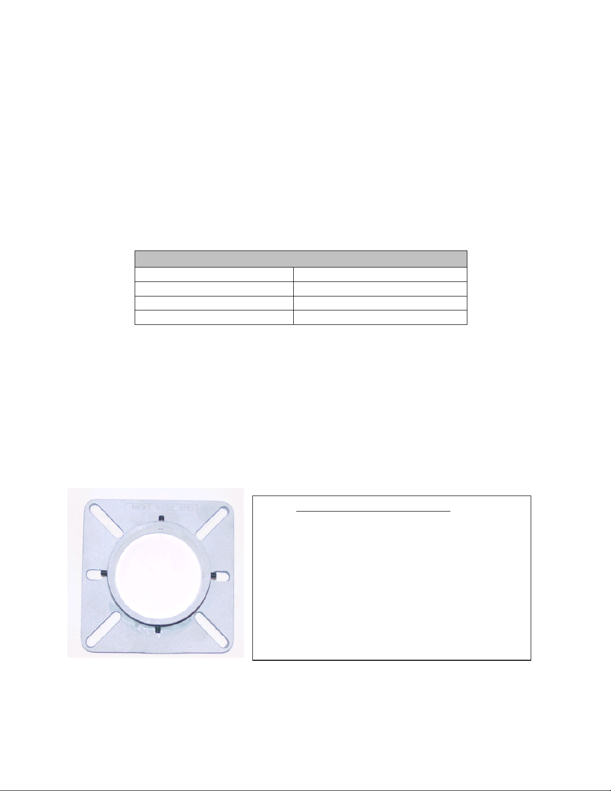
Refer to the pictures below to determine which flange is installed on the SU-2A
Picture 1: STANDARD FLANGE:
Install the gasket and the Standard flange to the
boiler. Tighten the bolts. Measure the boiler or furnacemounting plate to determine the flame tube insertion depth
required and make a mark on the tube (with a marker or
screwdriver). Deduct ¼” from the total length and tighten
the flange on the flame tube with the deducted insertion
depth. The ¼” deduction will prevent the tip of the flame
the proper depth and tighten the four ¼”off any free openings with either high temperature cement
or high temperature silicone.
Page 6

6
from the total length and tighten the flange on the flame tube with
depth and tighten the two setscrews using
o’clock stud. The second screw should be on the right (slightly above
2A gas burner into the boiler. Once the burner is
Picture 2: DIE CAST FLANGE: (picture to the left)
Install the gasket and Die Cast flange to the boiler.
Tighten the bolts. Measure the boiler or furnace-mounting plate
to determine the flame tube insertion depth required and make a
mark on the tube (with a marker or screwdriver). Deduct ¼”
the deducted insertion depth. The ¼” deduction will prevent the
tip of the flame tube from burning off. Slide the blast tube into
the boiler to the proper
a 4 mm allen key. Seal off any free openings with either high
temperature cement or high temperature silicone.
• For heat exchangers with a diamond stud pattern, one allen screw
on the flange should be on the top, slightly to the left of the 12
the 3 o’clock position stud). Tighten all the nuts equally. Make sure
that the allen screws are backed out, to allow enough clearance.
Then, insert the SUinserted and pushed all the way forward, tighten the allen screw on
the top of the flange. This screw MUST go into the grove that is on
the burner housing. Tighten the second allen screw, located on the
right side of the flange. This screw should be tight.
• For heat exchangers with a square stud pattern, move one of the
allen screws so that both are under the top two boiler studs. Tighten
the bolts and install the burner. Make sure the burner is straight and
tighten the allen screws.
• Seal off any free openings with either high temperature cement or
high temperature silicone.
Picture 2: BODY FLANGE: (picture to the left)
First, install the gasket and boiler flange to the boiler.
GAS SERVICE & PIPE CAPACITY
Before connecting the burner to the gas supply, insure that the gas pipes and service meter
are large enough to permit the additional load of the gas burner (see Chart 4).
Chart 4: Pipe Capacity Table*( x 1,000 BTU’s)
Nominal diameter of pipe in inches
Pipe Length**
15’
30’
45’
60’
75’
90’
105’
120’
150’
180’
* Using 0.6 Specific Gravity Gas and a Pressure Drop of 0.3” of Water Colum
**
Each 900 elbow counts as 3’ for the purpose of these calculations
¾” 1” 1 ¼” 1 ½”
172 345 750
120 241 535 850
99 199 435 700
86 173 380 610
77 155 345 545
70 141 310 490
65 131 285 450
120 270 380
109 242 300
100 225 225
n
Page 7

7
It is advisable to run a separate gas line from the meter to the gas burner to avoid pressure
drops. Refer to the above Pipe Capacity table for the correct sizes.
CONFORM TO LOCAL CODES.
cast iron parts
gas leaks using an approved gas leak tester.
Piping should consist of:
1. A shut off valve approximately 6’ away from the unit.
2. A 1/8” plugged NPT tapping for gas pressure measurement preferably on the manual shut off
valve (as shown or anywhere between the gas valve and the shut off value).
) with a suitable pipe dope that is resistant to liquefied petroleum gases. Test for
Use black steel pipe and malleable fittings (
ALL PIPING MUST
do not use
Note: The manual shut-off valve and tapping are NOT part of the SU-2A Gas Burner.
Please make sure you conform to local and state codes.
3. A gas union.
4. A drip pipe.
Caution: The gas valve should not be subjected to more than ½” PSIG. Therefore, the
burner should be isolated during high-pressure gas leak tests.
individual shut off valve must be disconnected from the gas supply piping system during any
pressure testing of that system at test pressures in excess of ½ psig. The appliance must be
isolated from the gas supply piping by closing its individual manual shut off valve during any
pressure testing of the gas supply piping system at test pressures equal to or less than ½ psig.
The appliance and its
Fig. 3 Gas Burner Piping*
*The dotted lines represent field installation.
To determine the firing rate of the burner, multiply the heating capacity of the appliance by
multiply the flow rate in GPH by 140,000 BTU/gal.
Example 2:
0.75 GPH x 140,000 = 105,000 BTU input rate.
Use the calculated input rate to fire the boiler or furnace.
if the boiler or furnace is rated for 0.75 GPH of No. 2 oil, then:
1.2
, or
Page 8

8
ORIFICE INSTALLATION
All burners are equipped with an orifice set at the minimum firing rate (except for OEM
packaged units). Drilling the orifice increases the firing rate. To drill the orifice, first open the
union and then unscrew the orifice from inside the union. Determine the proper orifice size for
the desired firing rate and drill the orifice (see Chart 5). Replace the orifice in the union and
tighten the union so that it is gas tight. Once installed, a higher or lower firing rate can be
achieved by raising or lowering the manifold pressure by +/- 0.3”. Pressure changes can only be
made when the burner is running. The typical working manifold pressure for natural gas is
W.C
. (2.3” W.C. for LP). The maximum inlet pressure at the gas valve is
minimum is
5” W.C.
(for the purpose of input adjustment).
Note: The manifold pressure may vary for OEM packaged units.
11” W.C
.; the
Chart 5: Burner Orifice Sizing For Natural Gas And LP*
Orifice Size
(inches)
5/32 0.156 50,000 50,000 21 0
3/16 0.188 80,000 80,000 18 2
7/32 0.219 90,000 90,000 12 6
15/64 0.234 122,000 122,000 18 14
9/32 0.281 146,000 146,000 14 11
19/64 0.297 160,000 160,000 10 10
27/64 0.422 200,000 200,000 3 15
1/2 no
* Assumes 0” to –0.02” Draft over fire
Drill
Size
orifice
Manifold Pressure at 3.5”
W.C. for Nat Gas (BTU)
250,000 250,000 1 20
Manifold Pressure at 2.3”
W.C. for L.P. (BTU)
Approximate
Head Setting
3.5”
Approximate
Air Setting
INSTALLING THE CHIMNEY LINER, DRAFT DIVERTER AND
VENT PIPE
Some utilities require new chimney liners for all gas installations. Use a corrosion resistant
chimney liner (approved for gas service) of the same size as the vent pipe. Use an CSA or U.L.
listed draft diverter only if you can maintain draft over fire. Otherwise, it is better to use a double
swing draft regulator, listed by CSA or U.L. When the burner is used as a conversion burner,
draft over fire should be maintained as –0.02” W.C. by adjusting the regulator when the burner is
fired. The installer should follow the barometric draft regulator manufacturer’s instructions for
complete details for installations and adjustments. The vent pipe should extend only to (but not
beyond) the inside wall of the chimney.
Page 9

9
ELECTRIC WIRING
These gas burners are manufactured for use with 120 volt, 60 cycle, single-phase electric
current. The installation must comply and be grounded in accordance with the National Board of
Fire Underwriters and National Electric Code ANSI/NFPA No. 70-1987 (or the latest addition).
All applicable local codes should be followed as well.
Installation wiring should be wired through each limit control or interlock, while operating
controls (like the thermostat) should be treated as 24-Volt wiring. The burner has its own 24 Volt
AC power supply. Do not add a 24 Volt AC transformer for the burner wiring. Do not use the 24
Volt transformer found on the burner to power other items in the heating system, such spill
switches, etc. Follow the wiring diagrams provided below:
Fig. 4 Wiring Diagram for Fenwal 2466H
SEQUENCE OF OPERATIONS
Fenwal 2466H 036-111
1. All limits are closed and 120-volt power is on for the burner.
2. T-T terminals are closed (24-volt power carrying lines; do not power this.) Sometimes, T-T
terminals are jumped with a wire nut for burners not set for post-purge.
3. Burner motor starts and pre-purge begins
4. Burner housing pressurizes and proves air flow - contacts closed. {Note: if the contacts are closed
before the motor starts, blower motor runs continuously. Diagnostic light flashes once every 3
seconds.}
5. At the end of pre-purge, ignition spark starts (audible sound) and the redundant gas valve opens for
4 seconds. (Trial for ignition)
6. Within 4 seconds, gas flame is established and the flame rod carries current to prove the flame
{Note: a minimum of 0.7 micro amps are required; 5 micro amps is not uncommon.}
7. Flame remains till operating limit is open. If T-T is used to fire the burner (field wired for postpurge), the burner will go into post-purge once the thermostat is satisfied (T-T open). These
burners have 60 seconds post purge.
8. If the flame is not established, the control will attempt ignition two more times before locking out
for 60 minutes. The control will then attempt to re-establish the flame every 60 minutes. To reset
the control, interrupt power for five minutes to start the sequence again.
Page 10
10
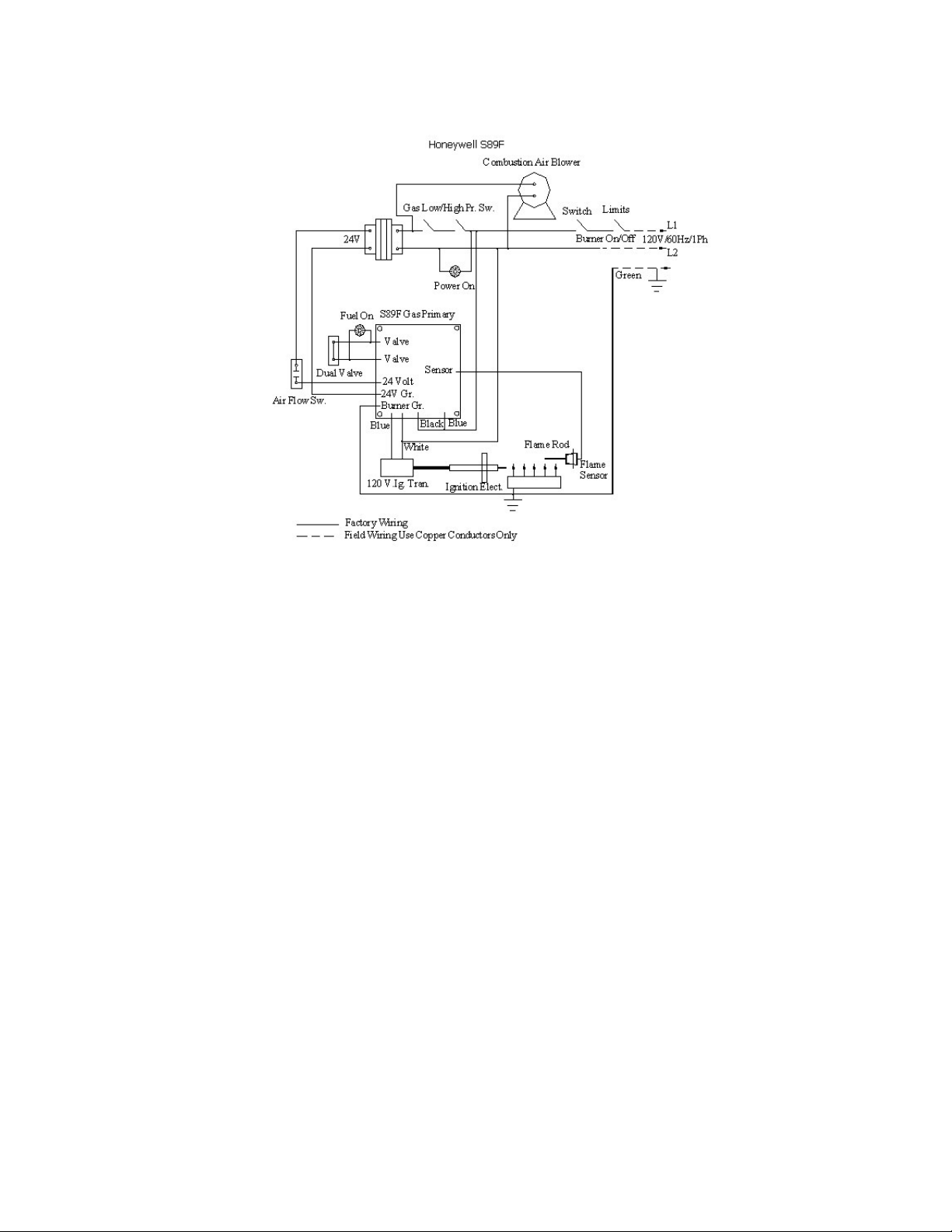
Fig. 5 Wiring Diagram for Honeywell S89F
SEQUENCE OF OPERATIONS
Honeywell S89F
1. Limits close.
2. Blower motor starts as the 24 Volt transformer powers the airflow switch.
3. Power from the airflow switch to the S89F control initiates 34 second pre-purge.
4. At the end of the pre-purge, the spark is energized for 4 seconds. At the same time, the 24
Volt transformer powers the gas valve, allowing the fuel to flow.
5. Within 4 seconds, the flame should be established and proved. The spark will shut off and
the control will hold power to the gas valve until the limits open and the burner stops firing.
6. If the flame is not established, the blower motor continuously runs.
7. To restart, power should be interrupted for five minutes. Then turn on the power to start
this sequence again.
Page 11

11
LIGHTING INSTRUCTIONS
To light the SU-2A Gas Burner
1. Set the thermostat to the lowest
temperature
2. The control knob on the gas
valve should be in the “OFF”
position for at least five minutes.
3. Rotate the control knob counterclockwise to the “ON” position
and set the thermostat to the
desired temperature settings
1. Turn the thermostat off, or turn the main power off
2. Wait five minutes
3. Turn the main power on
1. Rotate the control knob on the gas valve to the
“OFF” position
2. Set the thermostat to the lowest temperature
3. Turn Main Power Off.
Reset, if Flame Lockout Occurs
To shut the burner off
BURNER OPERATION
Before turning the burner on, check for gas supply leaks. Check the wiring diagrams; install
manometers before and after the gas valve. Keep the observation port of the boiler or furnace
open. Follow the instructions on the nameplate of the burner to turn it on. Follow the sequence
of operations for the control (see pages 9 and 10).
readings below.
BURNER OPERATION: Record the Readings at Steady State
Draft over fire at steady state (should be –0.02 “W.C. or zero)
NOTE: This may vary for OEM applications.
Natural Gas CO2 % = (9.0% to 9.8%) or O2 % = (5.0% to 3.5%)
LP Gas CO2 % = (10.5% to 11.5%) or O2 % = (5.0% to 3.5%)
Stack Temperature (300o F minimum, 550oF maximum)
Percentage of Carbon Monoxide (CO) in PPM
Incoming Gas/LP pressure = “W.C. (minimum 5”)
Natural Gas manifold gas pressure = “W.C. (3.5” required + - 0.3”)
NOTE: This may vary for OEM applications.
LP Gas manifold gas pressure = “W.C. (2.3” required + - 0.3”)
Carbon Monoxide in flue ( less than 100 PPM ideal; should not exceed
400 PPM Oxygen free)
Use a combustion analyzer and record the
Page 12
12
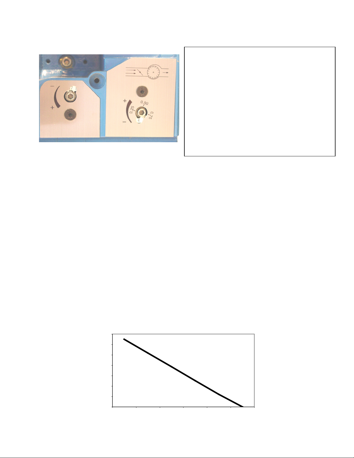
PICTURE 4: HEAD AND AIR ADJUSTMENT
Head Air
The air shutter is a mechanical shutter. Do NOT over crank the air shutter. General rule: if the
CO2 (Carbon Dioxide) is too low, then close the air shutter. If the CO2 is too high, then open the
air shutter.
If the CO (Carbon Monoxide) is above 100 ppm, there is either too much air or too little air.
Check the CO2 level and adjust the burner.
The retention head is 1/8” inside the tube when the marking reads ‘22’. There is a full ½”
movement for the retention disk to move backward (to increase secondary air) or forwards (to
decrease secondary air).
crank the head dial.
combustion area, up to 0.3” W.C.
Caution: If this is the case, the flange and the combustion chamber should be completely
sealed.
should be adjusted while it is firing.
Note: Do NOT set the CO2 higher than 9.8% for Natural Gas or 11.5% for LP Gas.
NOTE: the head physically moves within the blast tube. Do not over
This movement can also be used to compensate for backpressure in the
This pressure firing decreases as the firing rate increases. See Graph 1
To access the head and air adjustment, remove the
plastic cover from the rear of the housing, using
the supplied 4 mm allen key. The left dial is the
head adjustment dial; the right dial is the air
adjustment dial. These dials can spin 360o 22
times for the head and 32 times for the air. Using
the same 4 mm allen key, turn the numbered dials
to the appropriate head setting (please refer to
Chart 5 on page 8).
are only approximate settings. Actual field
conditions will vary and require a certified
technician to adjust the burner. OEM settings
may differ.
When to adjust the Air
When to adjust the Head
These recommended settings
. Note: the burner
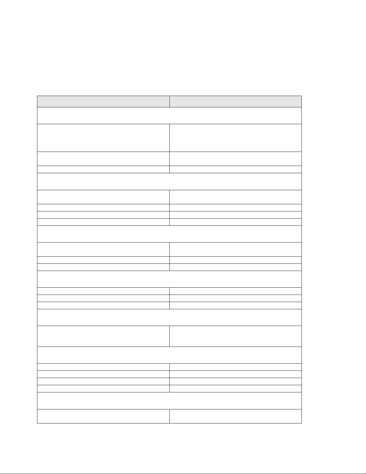
Graph 1: Chamber Pressure versus Firing Rate (BTU)
0.35
0.30
0.25
0.20
0.15
Inches of Water
0.10
0.05
0.00
50,000 100,000 150,000 200 ,000 250,000 300,000
BTU's
Page 13
13
Trouble shooting:
There are three factors to operate the gas burner properly:
1. Electricity {(main Power 120V/60 Hz /1 Ph)( secondary 24V)}
2. Gas flow (Incoming pressure should be 10” w.c. with proper gas line without pressure drop
during burner operation).
3. Combustion air.
Check these three items properly before proceeding in detail for other problems.
Condition Solutions
1. Burner motor runs and:
No flame after pre-purge & no fuel indicator (where
applicable)
No flame, fuel indicator on (where applicable),
faulty ignition transformer or spark separately
Fenwal control defective after above tests. Replace
2. Burner locks out after 4 seconds
First, check ionization electrode, ionization cable
Polarity reversed Check power feed for broken polarity
Bad earth grounding Fix the ground wire
Gas pressure is too low Check the gas pressure and adjust to proper pressure
3. Pulsation at start
First, check the burner head location with respect to
Gas pressure is too high. Use manometer and readjust the pressures.
Blocked Flue Check draft and clear flue of foreign materials.
4. Pulsation during operation
Burner is not correctly adjusted. Readjust with combustion analyzer.
The burner is dirty. Clean the burner.
Defective chimney Check and change if necessary with liners.
5. Burner locks out
Ionization current is too low. Check current. Minimum 0.8 micro amps. Check
6. The CO content is too high
Excess air is too high or too low. Adjust air shutter.
The gas holes are clogged. Clean them.
The fresh air intakes are too small. Check and readjust.
The burner head is out of position. Check and readjust.
7. Condensation in the heat exchanger
Firing Rate is too low. Increase the firing rate so that the stack temperature
Check 24V feed to airflow switch & after airflow
switch to control. Fix or replace the airflow switch.
If there is no secondary power, then replace the
24Vtransformer.
Check ignition transformer, electrode, cracked
electrode or gap. Fix or replace.
(for cracks) and boot. Fix as needed.
the end of the flame tube. Adjust as necessary.
position of ionization electrode and the condition of
the cable.
is 350o F or HIGHER. Insulate the chimney.
Page 14

14
ITEM
9A Silencer
10 Air Regulation Plate
11 Air Damper
12 Air Regulation Adjustment screw
13 Adjustment Screw – Nozzle Line
14 Ionization Cable
15 Ignition Transformer (cable included) 2709 or
PART PART #
1 Blast Tube
2 Flange Gasket
3 Adjustable Flange 10195 17 Scale - Nozzle Line
4 Front piece - Housing 17A Scale - Air Regulation 11887801
5 Rear piece – Housing
6 Fan Wheel
7 1/6 HP PSC Blower motor
8 Shielding Plate Housing
9 Outside Air Boot
11728410 16 Cover Plate - Air
10195-1 16A Cover Plate - Nozzle
18 24 Volt Transformer 2440VA
11417601 19 Safety Control 2466H or
D82132 20 Plastic Cover Plate 11850001
21 Screw (Long Special) 11750702
11859107 22 Airflow Switch
11879302 23 Ignition Electrode 115 34708
11851001 24 Flame Rod 115 34707
11852201 25 Retention head 119 39701
11848501 26 Union 1139101
11912901
11865805
5SAY
ITEM
27 Gas Valve
28 Brass orifice 12299
PART PART #
Regulation
Line
Honeywell/Tridelta
11887001
11887301
11888101
S89F
6041A
VR 8205A
2008 or
VR 8305 P
Page 15

15
Maintenance Instructions:
TO BE FIXED/ATTACHED NEAR BURNER
Once a year, a qualified service agency needs to be contracted for other than routine
maintenance.
1. The blower motor is the only moving part. It does not require lubrication, since the ball
bearings have been permanently lubricated.
2. The user should do periodic visual checks of the burner and the flame.
3. Laundry lint or dog and/or cat hairs should not go inside the blower. If they are seen, they
should be removed after disconnecting the power to the burner and cover parts should be
installed before starting the burner.
4.
Keep the area around the conversion burner clear and free from combustible materials,
gasoline, and other flammable vapors and liquids.
5.
No obstruction for the flow of combustion and ventilating air (ref. Page 4).
Page 16

16
 Loading...