

Page 1
User Guide
Ioline FlexJet E & StudioJet Printers
Page 2

User Notice
Trademarks
Ioline, StudioJet and FlexJet E printers are trademarks of Ioline Corporation. HP is a trademark of the
Hewlett-Packard Company. Other product names, logos, designs, titles, words or phrases mentioned
within this publication may be trademarks, service marks, or trade names of Ioline Corporation or other
entities and may be registered in certain jurisdictions including internationally.
Ioline Disclaimer
IOLINE CORPORATION PROVIDES THIS MANUAL “AS IS” WITHOUT WARRANTY OF ANY KIND,
EITHER EXPRESS OR IMPLIED, INCLUDING BUT NOT LIMITED TO THE IMPLIED WARRANTIES
OR CONDITIONS OR MERCHANTABILITY OR FITNESS FOR A PARTICULAR PURPOSE. IN NO
EVENT SHALL IOLINE, ITS DIRECTORS, OFFICERS, EMPLOYEES OR AGENTS BE LIABLE FOR ANY
INDIRECT, SPECIAL, INCIDENTAL, OR CONSEQUENTIAL DAMAGES (INCLUDING DAMAGES
FOR LOSS OF PROFITS, LOSS OF BUSINESS, LOSS OF USE OR DATA, INTERRUPTION OF BUSINESS
AND THE LIKE), EVEN IF IOLINE HAS BEEN ADVISED OF THE POSSIBILITY OF SUCH DAMAGES
ARISING FROM ANY DEFECT OR ERROR IN THIS MANUAL OR PRODUCT.
Limit of Liability Statement
It is the responsibility of the operator of the printer to monitor the performance of the printer and maintain it in proper working condition by following the instructions in this User Guide. It is the responsibility
of the operator of the printer to follow all safety precautions and warnings that are described in this User
Guide. Ioline Corporation is not responsible for injuries that may occur as a result of unsafe use. Ioline
Corporation is not responsible for substandard operational performance as a result of failure to maintain
the printer as described in this User Guide.
© 2003-2008 Ioline Corporation. All rights reserved. This manual may not be copied, photocopied, reproduced, translated, transmitted or converted to any electronic or machine-readable form in whole or in
part without prior written approval of Ioline Corporation.
Service and Support
If you require assistance with an Ioline product, your local Ioline dealer or authorized service center is
ready to help. Support information is also available 24/7 on the Ioline Web site—or you may contact Ioline
directly:
Ioline Corporation
14140 NE 200th Street
Woodinville, Washington 98072 U.S.A.
Ioline Customer Service Department
Monday through Friday
7:00 A.M. - 5:00 P.M. U.S. Pacic Time
Voice: 1.425.398.8282
Fax: 1.425.398.8383
support@ioline.com
www.ioline.com
Part Number 109619 Rev. 1
Page 3
Ioline FlexJet E
Printers
User Guide
Page 4

Table of Contents
Safety & Cautions
Visual Reference Guide
Chapter 1 Overview
Getting Started ................................................................................................. 15
How The Ioline FlexJet E and StudioJet printers Work ................................ 16
Chapter 2 Installation
Printer Assembly .............................................................................................. 17
Unpacking the Printer ......................................................................................................... 17
Assembling the Stand .......................................................................................................... 17
Attaching the Printer to the Stand ................................................................................... 17
Connect the printer to the Computer: Overview ....................................................... 17
Cable Connections .............................................................................................................. 18
Serial Conguration ............................................................................................................. 18
COM Port .............................................................................................................................. 18
Baud Rate ............................................................................................................................... 19
Other Serial Port Settings .................................................................................................. 19
Software Setup Options ..................................................................................................... 19
Power On ........................................................................................................... 21
Installing FlexPlot and the Control Center ................................................... 21
Chapter 3 Operation
Keypad Controls ............................................................................................... 23
Start/Stop ............................................................................................................................... 23
Clean ....................................................................................................................................... 24
Quality .................................................................................................................................... 24
Set Origin ............................................................................................................................... 24
Arrow Keys ............................................................................................................................ 25
Page Advance ......................................................................................................................... 25
Unroll (FlexJet E Only) ........................................................................................................ 25
Special Key Combinations .............................................................................. 25
Roll Up (FlexJet E Only) ..................................................................................................... 25
Reset Serial Port Baud Rate ............................................................................................... 25
Restore Factory Default Settings ...................................................................................... 25
The Control Center ......................................................................................... 26
Overview ................................................................................................................................ 26
Changing System Settings ................................................................................................... 26
Page 5

Control Center Menu Bar Features ............................................................... 27
File ........................................................................................................................................... 27
Communications .................................................................................................................. 27
Tools ........................................................................................................................................ 27
Help ......................................................................................................................................... 27
Control Center Menu Options ........................................................................ 28
Software Version ................................................................................................................... 28
Cartridge Count ................................................................................................................... 28
Get Plotter Data .................................................................................................................. 28
Plotter Data (check box) .................................................................................................... 28
Line Width .............................................................................................................................. 28
Scale ......................................................................................................................................... 28
Frame Size .............................................................................................................................. 28
Quality Setting ...................................................................................................................... 29
Measurement Units .............................................................................................................. 29
Consumables ..................................................................................................... 29
Paper ....................................................................................................................................... 29
Ink ............................................................................................................................................ 29
Guidelines for Installing a Cartridge
* ............................................................................................................................................... 29
Printing a Marker ............................................................................................. 30
Overview ................................................................................................................................ 30
General Guidelines .............................................................................................................. 30
Loading Paper on the StudioJet ...................................................................... 31
Loading Paper on the FlexJet E Printer ......................................................... 31
Installing the Take-up Shaft (FlexJet E Models only) ............................................ 32
Feeding Paper (FlexJet E Models only) ................................................................ 33
Tape Paper to the Take-up Shaft (FlexJet E Models only) .................................. 34
Positioning the Pinchwheels ............................................................................ 34
Insert Front Dancer Bar (FlexJet E Models only) ............................................... 35
Insert Read Dancer Bar (FlexJet E 2H+ Models only) ........................................ 36
Set an Origin ..................................................................................................... 36
Sending Plot Files ............................................................................................. 36
Pausing a Marker Plot ...................................................................................... 36
Canceling a Marker Plot .................................................................................. 37
Removing Markers from the Take-up Shaft (FlexJet E Models only) ................. 37
Manually Freeing the Take-up Shaft (FlexJet E Models only) ............................ 38
Automatically Freeing the Take-Up Shaft (FlexJet E Models only) .................. 39
Reattach Paper to the Take-up Shaft (FlexJet E Models only) .......................... 39
Printing to the Floor ........................................................................................ 40
Chapter 4 Routine Maintenance
Cleaning the Drive Shaft ................................................................................. 41
Cleaning the Platen and Traverse ................................................................... 41
Cleaning the Support Blocks (FlexJet E Models only) ....................................... 42
Size Calibration ................................................................................................ 42
Prepare the Printer (See the Operation chapter) ............................................................... 42
Use the Control Center to Gather the Calibration Data .......................................... 43
Enter the Calibration Data: ................................................................................................ 43
Cartridge Calibration ....................................................................................... 44
Prepare the Printer .............................................................................................................. 44
Motion Adjust (Carriage Scan Alignment) ..................................................................... 45
Frame Gap (Paper Scan Alignment) ................................................................................. 45
Page 6

Cartridge Maintenance and Handling ............................................................ 46
Check Cartridges ................................................................................................................. 46
Automatic Cleaning Procedure ......................................................................................... 46
Manual Cleaning Procedure ............................................................................................... 47
Print Cartridge Storage ................................................................................... 48
Short-term Storage (7 days or less) ................................................................................. 48
Long-term Storage (greater than 7 days) ........................................................................ 48
Updating Firmware using the Control Center .............................................. 48
Summary ................................................................................................................................. 48
Prepare the printer for a Firmware Update ................................................................... 48
Check the Current Firmware Version ............................................................................. 48
Update the Firmware .......................................................................................................... 49
Reset Calibration Values ..................................................................................................... 50
Chapter 5 Troubleshooting
General Troubleshooting .................................................................................. 51
Media Tracking .................................................................................................. 51
Printing Quality ................................................................................................ 52
Line Quality ....................................................................................................... 52
Serial Communication ..................................................................................... 52
Keypad Error Codes ......................................................................................... 53
Legend ..................................................................................................................................... 53
Common Issues ................................................................................................ 54
Common Issues (FlexJet E Models only) ............................................................. 57
Chapter 6 End Notes
Service & Support ............................................................................................ 59
Getting Help ..................................................................................................... 59
Customer Service ............................................................................................. 60
Your Comments Are Requested ..................................................................... 60
Before you contact Support… ........................................................................ 61
The FCC Wants You to Know... ........................................................................ 62
Glossary
Index
Page 7

NOTES
Page 8

NOTES
Page 9
The Ioline FlexJet E and StudioJet printers have many fast moving
components. Please read and follow these safety guidelines before
beginning operation of the printer:
n Do not try to repair the machine without factory authoriza-
tion. Only qualied service personnel should attempt any
disassembly or access to internal components. If external
mechanical adjustments are necessary, turn off the printer and
disconnect it from all power sources (both the computer and
the wall outlet).
Safety &
Cautions
n Be careful with hair, jewelry, or loose clothing near the printer.
They can become caught in the mechanical parts.
n Never attempt to move the carriage by hand when the power is
on. Always use the Arrow keys to move the carriage. To park
the carriage safely in
the Service Station
and protect the print
cartridges, press the
Clean button.
n Keep hands away
from the carriage
when the printer is in
operation. The car-
riage will automatically move to touch
the left end plate then
back to the right end
(the Service Station
position) when the
power is turned on.
n Never insert hands or other objects into the Service Station
area on the right side of the printer. The carriage occasionally
enters this area without warning and could collide with an
obstruction, potentially causing and injury.
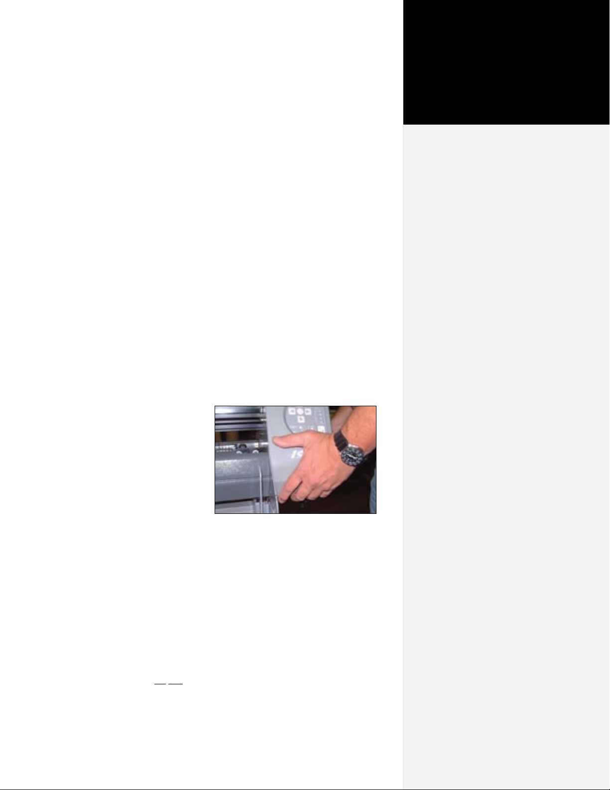
Figure 1. Hold the bottom surfaces of the
end covers to avoid injury to your ngers.
n Be careful when moving or lifting the printer. Moving the
FlexJet E printer requires at least 2 people. To avoid injury to
your ngers, do not lift either model by the end plates. Hold
the bottom surfaces of the end covers to lift or move them. See
Figure 1.
n Keep ngers away from the drive shaft when the printer is in
ix
Page 10
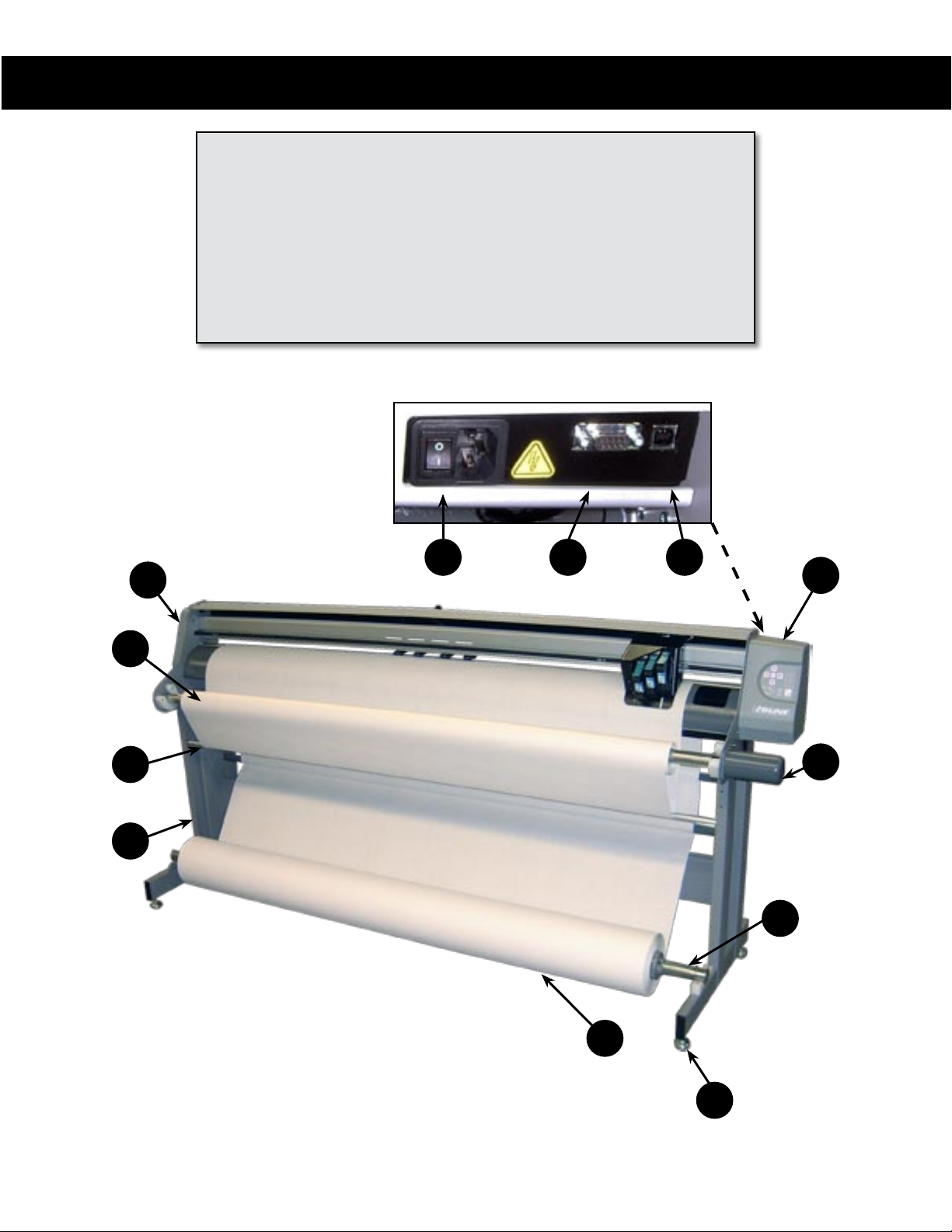
Visual Reference Guide
KEY
A
A. Left End Cover
B. Right End Cover
C. Take-up Motor
D. Stand Leveling Foot
E. Feed Roll
F. Take-up Shaft
Rear Panel Behind Right End Cover
G. Feed Shaft
H. Dancer Bar
I. Stand
AA. Power Switch
BB. Serial Port
CC. USB Port
AA BB
CC
B
F
H
I
C
G
E
D
x
The Ioline FlexJet E Printer Front View.
Page 11
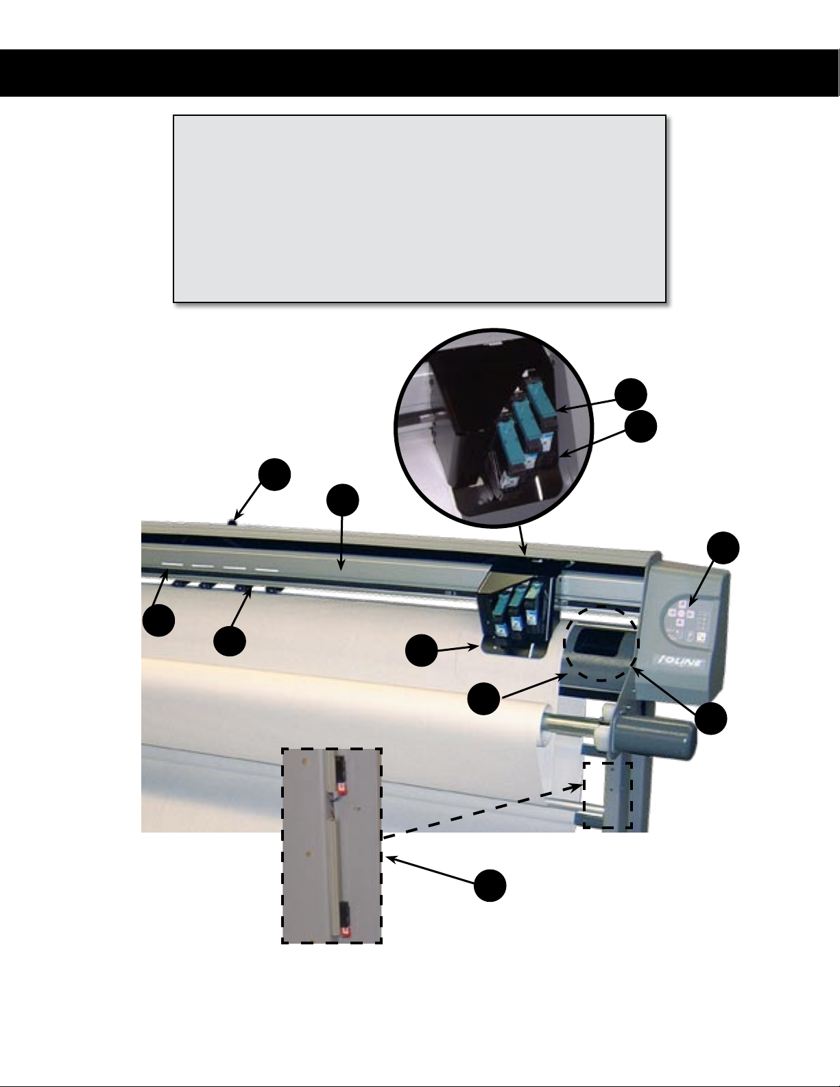
Visual Reference Guide
KEY
J. Drive Shaft Marker
K. Pinchwheel
L. Traverse or Carriage Rail
M. Carriage Assembly
N. Platen
P. Ink Cartridge Latch
R
L
Q. Ink Cartridge Stall
R. Pinchwheel Lever
S. Keypad
T. Service Station
U. Take Up Sensors
P
Q
S
J
K
The Ioline FlexJet E Printer Front View Close-up
M
N
T
U
Page 12
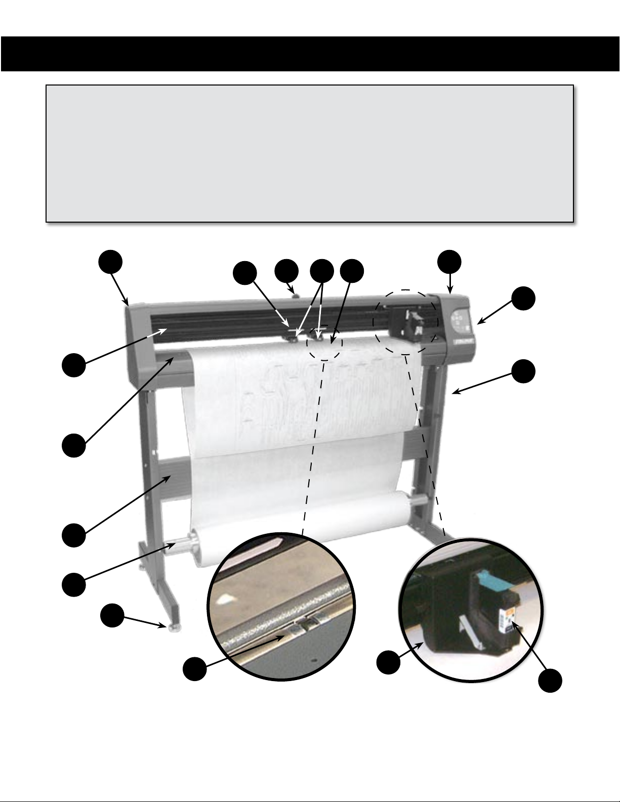
Visual Reference Guide
KEY
A. Left End Cover
B. Drive Shaft Marker
C. Pinchwheel Lever
D. Pinchwheel
E. Drive Shaft
A
O
F. Right End Cover
G. Keypad
H. Stand Leg
I. Inkjet Cartridge
J. Carriage
B
C
D E
K. Stand Leveling Foot
L. Feed Shaft
M. Cross-member
N. Platen
O. Traverse
F
G
H
N
M
L
K
E
Figure 5. The Ioline StudioJet Front View.
J
I
Page 13

Unless otherwise noted, diagrams and descriptions depicting Ioline FlexJet E printer models also apply to the
Ioline StudioJet in this manual.
Getting Started
Chapter 1
Overview
Thank you for purchasing the Ioline FlexJet E or StudioJet printer.
This manual contains instructions and guidelines for setting up,
operating and maintaining your Ioline printer. The following components are needed to create markers:
n A FlexJet E printer assembled according to the directions out-
lined in the FlexJet E Printer or StudioJet Quick Start Guide.
n A computer system that is properly installed and has a func-
tioning serial or USB port.
n Apparel design software loaded into the computer according to
the installation instructions.
n Printing media and ink cartridges that are within the guidelines
stated under the Operation chapter.
n Depending on the communications setup, Ioline FlexPlot soft-
ware is required if your CAD software does not create compat-
ible les.
i
In order to output to the FlexJet
E or StudioJet printer, your
apparel design software must
create plot les in HPGL 7475
or DM/PL format. Alternatively,
you can output markers using the
FlexPlot software, included with
the printer. FlexPlot imports and
converts a variety of le formats
for output to your Ioline printer.
i
Note
Note
The Ioline Control Center
and FlexPlot will only run on
the Windows® 2000/XP/Vista
operating systems. Most design
software provides drivers for
Ioline printers. Contact Ioline
customer service if you need assistance with drivers.
Page 14
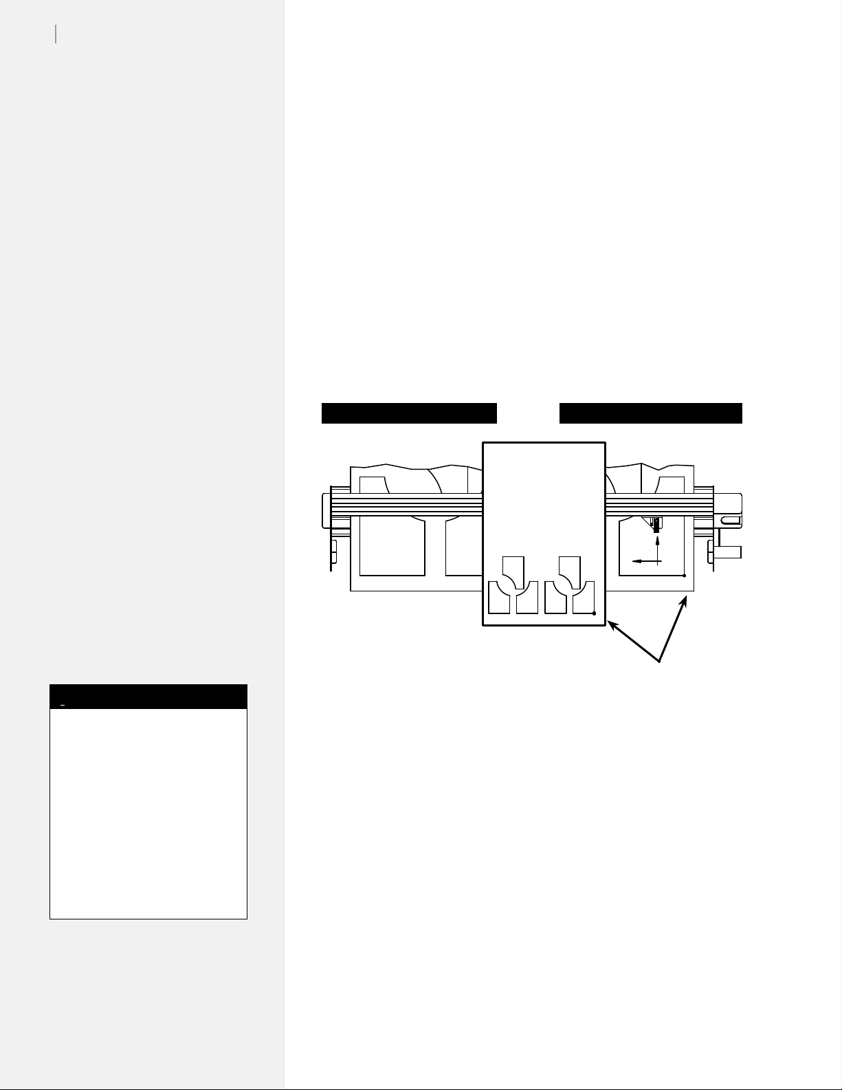
16
LEFT EDGE OF PLOT
LOWER EDGE OF PLOT
Y
Ioline FlexJet E User Guide
How The Ioline FlexJet E and
StudioJet printers Work
The FlexJet E and StudioJet printers create printed images through
synchronized media and carriage motion. Files are sent to the printer
from a computer or le server via a serial or USB* connection.
When the printer receives a le, the electronic logic system translates
the vector image into X-axis (paper motion) and Y-axis (carriage motion) instructions and uses digital feedback to ensure plot accuracy.
The FlexJet E and StudioJet printers break the plot le into frame
segments in order to plot long markers. The FlexJet E printer then
rolls the frame segments onto a take-up shaft. The FlexJet E printer
can roll up to 600 yards onto the take-up shaft at a time. The Studio-
Jet plots to the oor.
Left side of FlexJet E printer Right side of FlexJet E printer
i
In this manual the right and left
side refers to the right and left
side of the front of the printers.
Design software usually refers
to the Origin (or Start Point)
as “lower left” because it is the
lower left corner of a plot. The
plot is usually oriented in the
printer rotated 90 degrees counter clockwise as shown in Figure
5. The lower left corner of the
plot is physically on the right side
of the printer.
* Note: The StudioJet has a serial
port. The FlexJet E has both a se-
rial port and a USB port.
Note
Origin at right side of printer
and lower left on plot
Figure 7. The X- and Y-axes and origin (top view).
Page 15
An overview of the complete setup procedure is described
in detail in the FlexJet E Printer and StudioJet Quick
Start Guides (provided in the Accessory Kit).
Chapter 2
Installation
Printer Assembly
Unpacking the Printer
Carefully remove the printer from the box and place it on a at,
stable surface. This procedure requires two people. Check the packing list to ensure that all of the accessories are present. (See the FlexJet
E printer or StudioJet Quick Start Guide for more information.) Save all
packing materials and the box.
Assembling the Stand
Assemble and level the stand using the hardware included in the Accessory Kit and directions outlined in the See the FlexJet E printer or
StudioJet Quick Start Guide.
Attaching the Printer to the Stand
Attach the printer to the stand with the top bars resting in the
notches in the stand legs. Use the hardware as indicated in the See the
FlexJet E or StudioJet Quick Start Guide.
Connect the printer to the Computer: Overview
Connect the printer to your computer via serial cable (provided in the
Accessory Kit). The corresponding serial port on your computer may
be either a 9-pin or 25-pin male receptacle. If the computer has 25-pin
serial ports, a 25- to 9-pin adapter is necessary.
Once connected, select the correct port and data rate in your apparel
design software, FlexPlot and/or the Control Center. Consult the
design software manual or the dealer for further information. Information on conguring FlexPlot and the Control Center follows in
the Operation chapter.
Caution
Do not hold the printer
head by the bottom edge
of the end plates when
attaching it to the stand. Fingers
and hands might get pinched
between the end plates and stand
legs. Hold the bottom of the end
covers when handling the printer.
(See Figure 1.)
Caution
Before connecting the
printer to your PC, make
sure the computer and
the printer both have the power
turned off. Ioline recommends
using a surge protector power
strip for both the printer and the
computer.
Page 16
18
Ioline FlexJet E User Guide
Cable Connections
When connecting the printer to the computer by serial cable:
1. Make sure that power to the printer is off. Power is off when
the switch is in the “0” position, and is turned on when placed
in the “1” position.
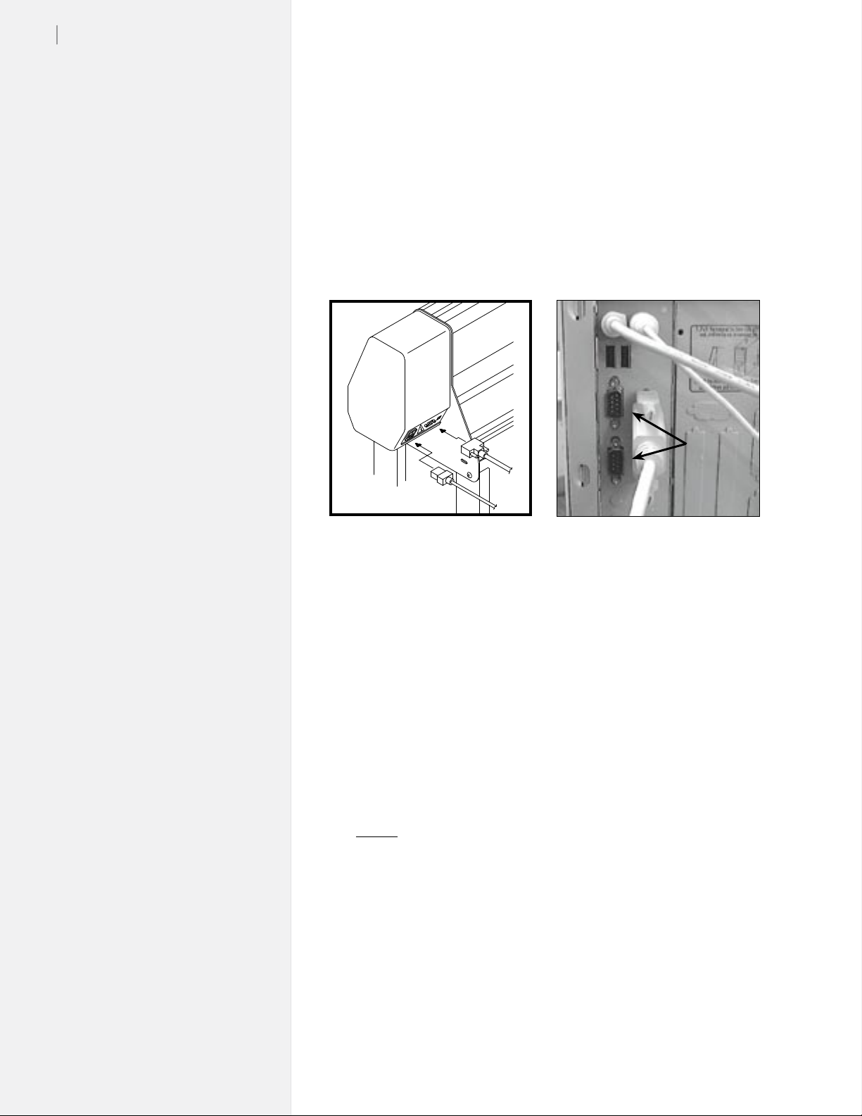
2. Connect the supplied serial cable and power cord to the panel
on the back right end cover of the printer. Lock the serial cable
to the port on the printer with the thumb screws.
COM
Ports
Figure 8. The serial cable and power
cord plug into the sockets in the back
of the right end cover.
3. Plug the printer power cable into a wall socket or a surge protector.
4. Make sure that power is off to the computer.
5. Connect the serial cable to a 9-pin male serial port on the back
of the computer. (If your computer has a 25-pin connector,
acquire a 25-pin to 9-pin serial adapter to make the connection.)
Tighten the thumbscrews.
Figure 9. PCs typically have two 9-pin
serial ports, COM 1 and COM 2.
Serial Conguration
It is critical that the Control Center, FlexPlot software, and any other
software that send data to the printer use the same COM port and
baud rate that the printer is using.
COM Port
A PC typically has two external 9-pin male serial connections.
These ports are often listed in the system settings as COM 1 and
COM 2. Determine which port is connected to the printer, then
select that port in all the software as instructed in the respective
software user guides. (See Figure 10.)
Page 17

Figure 10. FlexPlot Serial Port set-up window.
Baud Rate
The serial port on the printer has an adjustable baud rate. Available
speeds are 9600, 19200, 38400, 57600, and 115200. The default is set
at the factory to 38,400. The baud rate is adjustable in the Control
Center in the Communications>Settings window.
Chapter 2: Installation
19
Other Serial Port Settings
You may also need to set additional serial port settings, for instance,
when you use a terminal program. The recommended conguration
settings are:
Data Bits: 8
Parity: None
Stop Bits: 1
Flow Control: Software or Xon/Xoff
Software Setup Options
Ioline recommends using FlexPlot for marker making on the printer. FlexPlot offers the most robust and exible workow available
for creating output. It’s especially useful when many le formats are
used, a common situation for service bureaus. To set-up and learn
how to use the software, see the FlexPlot User Guide.
The printer is designed to work in many different production environments. The type of marker printing you do will often determine
your preferred communication method. Two typical methods for
sending markers are:
1. Plot directly from the marker or design software to the
printer. (See Figure 11.)
Unlike other marker printers, the FlexJet E and StudioJet print-
ers are capable of operating as stand-alone devices with no extra
software running on the computer. This method works if your
CAD software includes a driver for any Ioline product, such as
the Ioline 600Ae or the Summit 2200. It will also work if the CAD
software can create a compatible HPGL- or DM/PL-formatted le.
Page 18

20
Ioline FlexJet E User Guide
CAD
Software
HPGL
DM/PL
FlexJet E printer
Figure 11. Workow: output direct from CAD software (without FlexPlot).
2. Use FlexPlot software to convert les before sending them
to the printer for output.
The printer includes the FlexPlot software which will convert
many different les into a format that is compatible with the
printer. It also provides an advanced marker queue management system and other tools to optimize the performance of the
printer.
CAD
Software
[Network]
FlexPlot
HPGL
DM/PL
DXF
ASTM 6959
STD
(Alternate Conguration)
CAD
Software
+
FlexPlot
FlexJet E printer
Figure 12. Workow using FlexPlot for le conversion and output.
Page 19
Chapter 2: Installation
21
Power On
Turn on the computer and the printer to make sure they both work.
The printer power switch is located next to the power cord on the
back of the machine, behind the keypad. When the paper is properly
loaded and the printer is powered up, the carriage will move toward
the left side of the machine, then return to the opposite side to park
in the Service Station. The OK light will turn red and the Square
light will turn green on the front panel after the start-up process has
nished.
If no paper is loaded when the printer is powered up, the printer
displays an error message. The OK light will turn red and the Circle
light will turn orange. This combination of lights indicates a paper
out error. The keypad buttons do not work unless paper is properly
loaded—or a small piece of masking tape is placed over the Paper
Out sensor on the back of the printer. Once paper is loaded or the
sensor is taped over, press the Start/Stop button to clear the orange
circle and regain use of the keypad.
Installing FlexPlot and
the Control Center
The printer includes two software interfaces: FlexPlot and the
Control Center. FlexPlot will import and queue plot les from
many design programs to optimize production operations. The
Control Center is an interface for adjusting parameters to optimize
printer performance. The printer comes with a CD-ROM which has
Microsoft Windows® 2000/XP/Vista versions of the programs as
well as PDF user guides and the required Adobe® Acrobat® reader.
Caution
Keep hands and loose
clothing away from all
moving parts of the
printer. Make sure the Service
Station opening in the right end
plate is not obstructed and that
the stall latches are lowered.
i
In this manual the right and left
side refers to the right and left
side of the front of the printer.
Design software usually refers
to the Origin (or Start Point)
as “lower left” because it is the
lower left corner of a plot. The
plot is usually oriented in the
printer rotated 90 degrees counter clockwise as shown in Figure
5. The lower left corner of the
plot is physically on the right side
of the printer.
Note
1. Power on the computer and Windows®.
2. Insert the Ioline CD-ROM into the CD-ROM drive (usually D:).
3. The installation program should start automatically. If it does
not:
a. Select the Start button.
b. Choose Run.
c. Type D:\IOSETUP (substitute the correct letter if the CD-
ROM drive letter is not D:) and Click OK.
4. Follow the instructions that appear on the screen.
5. The FlexPlot User Guide has details on using the FlexPlot
software. In this manual, see the section The Control Center for
more details about the Control Center software.
Page 20

22
Ioline FlexJet E User Guide
This page intentionally left blank
Page 21
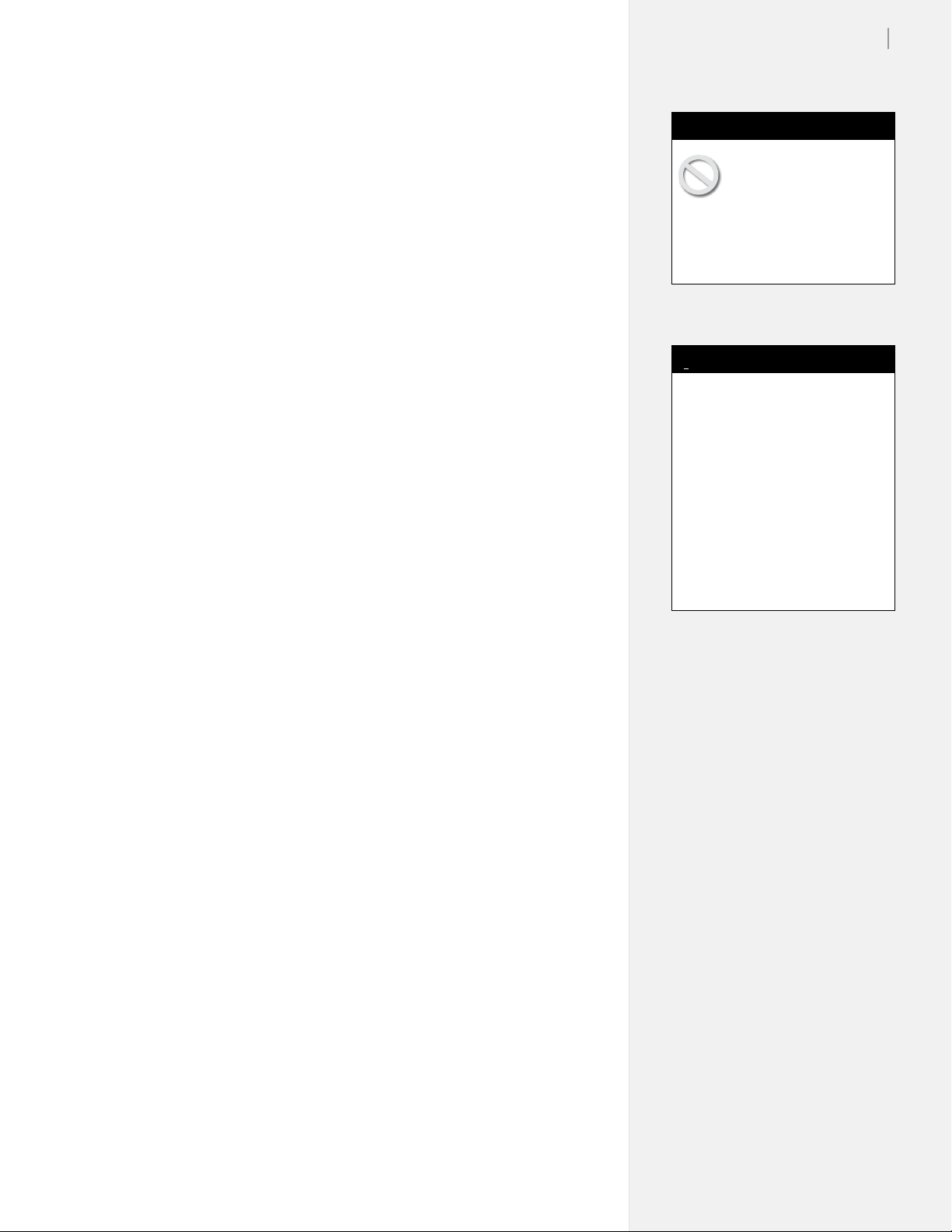
Keypad Controls
The keypad provides access to the main functions of the printer.
Chapter 3
Operation
Figure 13. The Printer Keypad.
Start/Stop
The Start/Stop key toggles the printer online and ofine. If the Start/
Stop key is pressed during printing, the OK light turns red and
the machine will stop after it nishes printing the current scan. The
Arrow, Unroll and Paper Advance keys are active when in STOP
mode. When the Start/Stop key is pressed again, the printer enters
START mode, the OK light turns green and printing resumes exactly where it stopped.
START mode OK = green Arrow keys inoperable,
printer online (ready to receive instructions).
STOP mode OK = red Arrow keys operable,
printer ofine (not ready to
receive instructions).
Page 22
24
Ioline FlexJet E User Guide
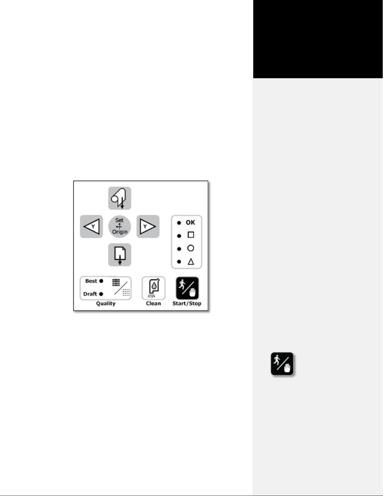
Clean
Runs the print heads through a cleaning cycle in the Service Station.
Put the printer in STOP mode and wait until the OK light turns red.
Then press the Clean button. If the carriage is not already parked,
it will return to the Service Station. After auto cleaning, the printer
will react differently when you put it in green light (START) mode,
depending on what it was doing just prior to the cleaning:
Printer state before auto cleaning—e.g.
what the printer is doing just before it is put
in STOP (red light) mode
Printing in START mode (OK light is green) Resumes printing
Idle in START mode (OK light is green) Stays parked and capped.
Idle, in STOP mode (OK light is red) Stays parked and capped.
Printer reaction when put in
START mode after auto cleaning
Quality
Switches between the Best—or dark (600 dpi)—line mode and Draft
mode (300 dpi), which prints lighter and consumes less ink. You can
change line quality while the printer is printing.
Set Origin
The Set Origin key sets the initial origin or starting position for the
marker. It’s best to always set a new origin point after cycling power.
To set a new origin, press Start/Stop until the OK light turns red
(STOP mode). Use the Arrow keys to move the carriage so that the
white marker is positioned over the desired starting point. Press the
Set Origin key. The OK light will turn green, indicating the printer
is ready to accept plot les. (See Figure 14.)
i
Apparel design software usually
refers to the origin as “lower
left” because it is the lower left
corner of a marker. Because the
plot is usually oriented as shown
in Figure 5, it is physically on the
right side of the printer.
Note
Origin Marker
Figure 14. The Set Origin key sets the marker origin point directly below the
top of the white origin marker on the carriage base—located on the right side.
Page 23

Arrow Keys
Pressing the Arrow keys moves the carriage left or right. The Arrow
keys are only active in STOP mode (see Start/Stop), when the OK
light is red.
Page Advance
Pressing this button advances the paper in small increments. This is
useful if a plot was removed from the printer and you need a paper
leader to tape to the take-up shaft. The Page Advance key is only active in STOP mode (when the OK light is red).
Unroll (FlexJet E Only)
Unroll Material – Press the Start/Stop button until the OK light turns
red. Press and release the Unroll button. The printer will unroll a
short segment of paper from the take-up shaft.
Automatic Unroll – Press the Start/Stop button until the keypad
light turns red. Press and hold the Unroll button. The printer will
automatically unroll paper. To cancel Automatic mode, press the
Start/Stop key again.
Chapter 3: Operation
i
For more details on removing
plotted markers from the take-up
shaft see Removing Markers
from the Take-Up Shaft later in
this chapter.
Note
25
Special Key Combinations
Roll Up (FlexJet E Only)
Use this function to roll material back onto the take-up shaft. Press
and hold the Unroll and Right Arrow buttons at the same time. The
rolling will continue until the dancer bar reaches the optical sensor.
The Roll Up key is only active in STOP mode (when the OK light is
red).
Reset Serial Port Baud Rate
This key combination will restore the serial port baud rate to the
default speed of 38,400. This is useful for diagnostic testing of the
communication system. Turn power off. Press and hold the Page
Advance key as you turn power on again. Continue holding the key
down until the OK light turns red and the Square light turns green.
Restore Factory Default Settings
This function replaces settings that are not working properly and can
be used when manual calibration is unsuccessful. This key combination will restore all calibration values to the factory defaults. Turn
power off. Press and hold the Unroll key as you power up again.
Continue holding the key down until the OK light turns red and the
Square light turns green.
+
+
+
1
0
1
0
Page 24

26
Ioline FlexJet E User Guide
i
To avoid communication port
conicts, do not simultaneously
run more than one application
that communicates with the
printer.
Note
The Control Center
Overview
The Control Center is a utility program that does two things:
n Allows you to adjust settings to tailor output (e.g. scale, line
width) from the computer.
n Provides an interface to send completed les to the printer.
Figure 15. Control Center Main Menu.
Changing System Settings
A variety of settings are adjustable to t specic needs:
n Make sure the printer power is on and that the initialization
process is complete. The carriage will park, the keypad OK
light will turn red and the Square light will turn green.
n The Screen Menu displays the primary settings that are adjust-
able. The Menu Bar contains utilities for setting up the Control
Center and calibrating the printer.
n Changes only take effect after one of the Send buttons is
pushed.
Page 25

Control Center Menu Bar Features
File
Send Plot File Print a PLT or PLX le.
Download Firmware Allows the user to download the lat-
est rmware version for the printer.
See the section Downloading Firmware in the Routine Maintenance
chapter for more information.
Exit Exit the Control Center.
Communications
Settings Select the COM port and baud rate
to match the printer.
Send Command Permits advanced users to manually
enter commands.
Chapter 3: Operation
27
Automatic Buffer Creates an End of Frame command
Closing after a long communications delay.
By default this is set to On. Turn off
for MAC computers.
USB Info USB Info displays hardware and
driver information about the direct
USB connection.
Tools
Aux Sensor When checked, disables the Paper
Out sensor. The default is On. (The
Paper Out sensor is an option on the
printer.)
Cartridge Calibration Displays tools to adjust print
cartridge alignment. See Routine
Maintenance for more details.
Size Calibration Allows adjustment of the size cali-
bration settings. See Routine Main-
tenance for more details.
About Your FlexJet Displays the licensing status of the
machine.
FlexJet Licensing Displays the licensing status and
licensing updates.
Help
Contents Displays the Help le.
About Displays Control Center version
information.
Page 26

28
Ioline FlexJet E User Guide
Control Center Menu Options
Firmware Version and Base
Displays the current rmware version installed in the printer.
Enabled Heads
Displays how many cartridges are in active use by the printer.
Get Plotter Data
Reads and displays the current settings stored in the printer.
Plotter Data (check box)
Indicates when the displayed settings were successfully downloaded
from the printer. If this box is unchecked, the Control Center was
unable to connect with the printer Check the connections, baud rate
and COM port . Press the Get Plotter Data button to attempt to
download settings if the process failed during startup.
Loop Length
Controls the length of the take-up paper loop in the front of the
machine. Shorter loops can help reduce paper jams when using challenging material like heat seal or very thin paper.
Line Width
Controls the weight of the plotted line using line width. Three levels
are available; Thin, Normal, and Thick. Thin lines use less ink and
make ne details like Asian text and small pieces easier to see. Thick
lines use more ink to produce higher contrast lines. Used in conjunction with the Quality Setting (see below), the printer provides six options to produce visible lines using the least possible amount of ink.
Scale
The printer scale ranges from 1% to 999%. The factory default Scale
is 100%. A scale set to 50% prints at half size. Changes do not take
effect until the Set Scale button is pressed. Note: Both X- and Y-axes
are set independently.
Frame Size
Most design software sends long plots to printers by breaking them
into smaller pieces called frames. In general, design software does this
automatically and adjusts the Frame Size in the printer to match.
The Frame Size setting establishes clipping limits for each data
frame. If the printed size of a plot frame exceeds the frame size set
in the printer, the excess is clipped or thrown away. (If the plot is
clipped, try increasing the Frame Size manually.) The factory-set
Page 27

X-axis (paper direction) frame size is 46-in (116.8-cm), maximum is
21600-in (54,864-cm). Default and maximum Y-axis (carriage direction) frame size is 72-in (182.9-cm).
Quality Setting
Choose Draft or Best to control line density. Draft mode uses 300 DPI.
Best mode uses 600 DPI. A lower DPI setting uses less ink by creating
a fainter line. Higher DPI uses more ink but makes a darker line. Use
this setting in conjunction with the Line Width (see above) to nd a balance between saving ink and making clearly visible lines.
Measurement Units
Choose between English or Metric units for settings display.
Consumables
Chapter 3: Operation
29
Figure 16. The Hewlett-Packard 51645A (‘45’ cartridges)
are widely available.
Paper
Ioline recommends 27 to 35 pound recycled or bond paper, 36- to 74-in
(91- to 188-cm) wide. The feed system supports rolls up to 600 yds long.
Ink
The Ioline FlexJet E and StudioJet printers require Hewlett-Packard
51645A or ‘45’ cartridges.
Guidelines for Installing a Cartridge
1. With the printer in STOP mode (red OK light), press the left
arrow key to move the carriage out onto the platen away from
the right end plate.
2. Open the blue stall latch and remove the old cartridge if one is
present. Squeeze the handle between your ngers and pull forward, then up.
*
Page 28

30
Ioline FlexJet E User Guide
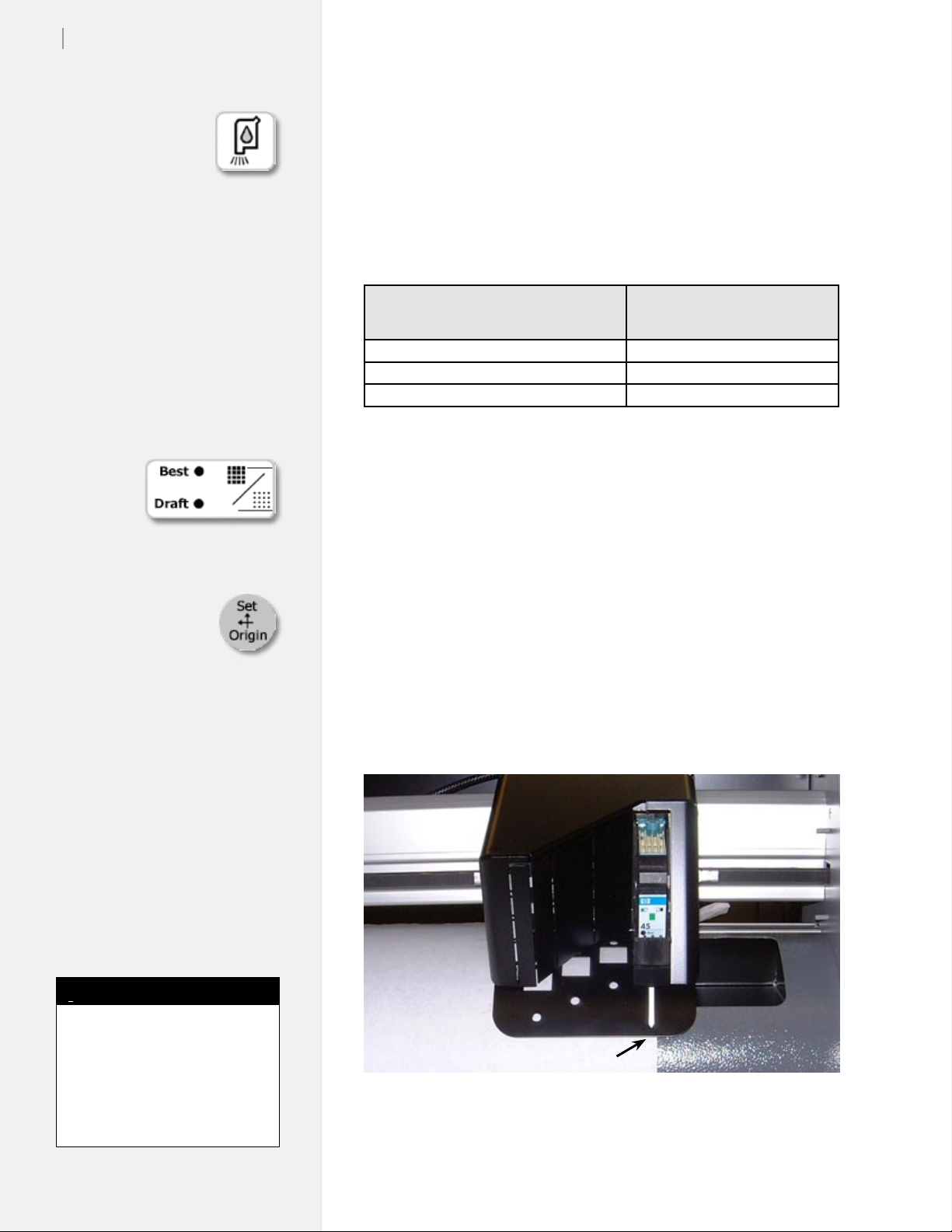
Figure 17. Insert ink cartridge at an angle into the cartridge bay. Lock in place with
the stall latch.
3. Insert the new cartridge with the print head pointing down
toward the rear of the stall and at a slight outward angle. Press
rmly while rotating the top of cartridge toward the back of the
stall until it stops in an upright position. (See Figure 17.)
4. Close the stall latch. If the cartridge is inserted properly, the
latch will snap shut and securely hold the cartridge. Do not
force the latch. If the latch does not close properly, remove and
reinsert the cartridge.
Printing a Marker
Overview
The basic steps required to print a marker on the printer are:
1. Turn the printer and computer power on.
2. Load paper.
3. Install cartridge in the stall.
4. Set an origin.
5. Start FlexPlot or your design application.*
6. Send marker/plot les.
These steps are outlined in the next several sections. In most cases
the design les are sent to the printer from FlexPlot or the design ap-
plication. If necessary, use the Ioline Control Center to send design
les or adjust settings.
* Refer to the FlexPlot User Guide
for information on set-up and
conguration.
General Guidelines
1. Good paper loading makes good plots. Follow loading instructions carefully.
2. Ensure that the paper roll is properly loaded on the feed shaft.
Paper width determines the roll’s position on the shaft.
3. Keep the plastic feed shaft block clean and well lubricated.
4. Use the FlexPlot software for optimal le management and
printing throughput.
Page 29

Chapter 3: Operation
31
Loading Paper on the StudioJet
See the StudioJet Quick Start Guide.
Loading Paper on the FlexJet E
1. Before loading a new paper roll always make sure the drive shaft
is clean. See the Routine Maintenance section for more details.
2. Place a paper hub in each end of the paper roll using a rubber
mallet.
3. Slide the feed shaft through the paper hubs and the paper roll.
If a paper hub falls out, press it rmly back into the end of the
paper roll and re-seat it with a rubber mallet.
4. For paper narrower than 70-in, center the paper roll on the feed
shaft. Make sure the hubs remain securely in place. For paper
greater than 70-in in width, offset the paper to the left slightly
to avoid covering the Service Station area. Also leave a minimum 1/4 inch gap between the paper edge and the edge of the
fan on the left side of the rear cover of the machine.
5. Use the supplied hex wrench to tighten both screws on each
paper hub.
6. Check that the right support block is clear of debris and apply a
light coating of white lithium grease (found in the Accessory Kit.)
Caution
Keep hands and loose
clothing away from all
moving parts.
7. Lift the feed shaft ends, one at a time, into the support blocks.
Support
Block w/
Bearings
Feed
Shaft
Paper Roll
(Unrolls from behind)
Support Block
(apply grease)
Hint
The FlexJet Set-up, Operating and
Maintenance Video, provided on
CD-ROM in the Accessory Kit,
provides a helpful visual overview.
i
Note
Paper Hub (2)
Figure 18. Installing the feed shaft. (As shown on the FlexJet E model.)
Flanged Coupling
Make sure the paper unrolls from
behind and towards the printer.
Page 30

32
Ioline FlexJet E User Guide
Caution
Never touch the take-up
key or anged coupling
while they are rotating.
Serious
personal
injury
could re-
sult. Turn
power off
rst.
Installing the Take-up Shaft
(FlexJet E only)
The Paper Out sensor on the back of the printer detects when the
paper runs out. If paper isn’t loaded or if the take-up key is not positioned properly, place a small piece of masking tape over the Paper
Out sensor before following the steps below. Remove the tape after
the take-up key is properly positioned before installing paper.
1. If the take-up shaft has plotted markers on it, remove them. See
Removing Markers from the Take-up Shaft later in this chapter.
2. Turn the printer on (the switch is on the back of the left cover.)
3. Use the keypad Unroll key to rotate the take-up key until it is
oriented perpendicular to the support block opening as shown
in Figure 19.
4. Put the take-up shaft into the front support blocks with the
anged coupling at the right (keypad) end. Rotate the shaft
until the slot in the anged coupling is aligned with the take-
up key. When the shaft slot and the key are aligned, push the
Rectangular
slot
Take-up
Shaft
Figure 19. Installing the take-up shaft in the support blocks.
Flanged
Coupling
Position take-up
key as shown
Support Block
Page 31

take-up shaft into place until it is seated in the support block.
Feeding Paper
(FlexJet E only)
Figure 20 represents the proper paper path. The left side of the diagram shows the paper path for a 1H FlexJet E. The right side shows
the proper path for a FlexJet E with 2 or more heads.
1. Remove any printed markers from the take-up shaft and make
sure the carriage is parked in the Service Station before feeding
the paper. (To park the carriage, press Start/Stop. Wait for the
OK light to turn red and press the Clean button.)
2. If the pinchwheels are lowered, raise them by pushing the
pinchwheel lever away from the machine.
3. Pull a long leader of paper off of the paper roll and insert it
through the stand, behind the plotting head between the platen
and pinchwheels.
Chapter 3: Operation
33
4. Temporarily lock the paper in place by pulling the pinchwheel
lever toward the machine to lower the pinchwheels.
Front
Dancer Bar
Take-up
Shaft
Feed Roll
Proper Paper Path
1H FlexJet E
Figure 20. The correct paper feeding path on the Ioline FlexJet E printers. (See the
StudioJet Quick Start Guide for paper path instructions for the StudioJet.)
Proper Paper Path
2H+ FlexJet E
Page 32

34
Ioline FlexJet E User Guide
i
When installing or retaping paper,
remove the front dancer bar and
set it aside.
Note
Tape Paper to the Take-up Shaft
1. Stand in front of the machine.
2. Place 3 short pieces of masking tape within easy reach on the top
cover. (See Figure 21.)
3. Holding the edge of the paper with one hand, use your free
hand to lower the pinchwheel lever to raise the pinchwheels.
4. Grasp the front edge of the paper with both hands and pull
20-in (51-cm) of paper over the platen and gray top bar and
under the take-up shaft. (See Figure 20 for the proper paper path.)
5. Add tension to the feed roll by applying gentle pressure using
the bottom of your foot.
6. To align the paper, gently pull it forward and side to side until
the tension feels even.
7. Press and hold the paper on the center of the platen with your left
hand, then lower the pinchwheels to lock the paper in place.
8. Attach the paper to the take-up shaft in the center and 2-in (5-cm)
from each end with the tape.
Do not cover the hole in
the platen with paper.
Tape the paper
in 3 places
Figure 21. Taping the paper to the take-up shaft.
Positioning the Pinchwheels
Pinchwheel position does not correspond to paper size. Always place
all pinchwheels at the machine center.
1. Ensure that the paper is loaded as described in the previous steps
and is taped to the take-up shaft.
2. Raise the pinchwheels by pushing the pinchwheel lever away
from the machine.
Page 33

Chapter 3: Operation
35
Pinchwheel
White Driveshaft Markers
Drive Shaft
Segment
3. Make sure that the paper roll is tight on the feed shaft.
4. Move the pinchwheels into their proper positions over a tread and
under the white markers on the traverse rail. (See Figure 22.) Do
not place pinchwheels over drive shaft bearings.)
5. Lower the pinchwheels.
Drive Shaft
Bearing
Figure 22. Positioning the pinchwheels.
i
Ensure that the paper roll is centered on the feed shaft.
Note
Insert Front Dancer Bar
(FlexJet E only)
1. With the pinchwheels lowered, hold the paper in place over the
rear top bar.
2. Insert the front dancer bar into the dancer bar channel.
Front Dancer
Bar (Silver
light rod)
Figure 24. Inserting the dancer bar.
Page 34

36
Ioline FlexJet E User Guide
Insert Rear Dancer Bar (2H+ FJE Models Only)
1. FJE models with two or more printheads and the high speed
printing kit require that a heavy dancer bar is inserted in the
rear dancer bar channel (see paper path in Feeding Paper).
2. Take the heavy dancer bar (painted black on some models) and
insert the ends into the notches in the stand legs on the back of
the machine as shown in the image below.
3. Use a hand on the rear rolling bar to slow rotation as the dancer
bar slides into the channel and forms a rear paper loop.
Notch in Stand Leg
* See the FlexPlot User Guide or
your design application user guide
for information on how to send
les to the printer.
Set an Origin
1. Ensure that cartridges are installed in the carriage stall(s). (See
Guidelines for Installing a Cartridge earlier in this chapter.)
2. Turn on the power. After a brief pause, the carriage will glide to
the left end plate, then return to the Service Station. When nished, the OK light turns red and the Square light turns green.
3. Press the Left Arrow key to position the carriage so that the tip of
the white marker is over the desired starting point of the plot.
4. Press the Set Origin key. The OK light will turn green. The
printer is ready to plot.
Sending Plot Files
Send plot les to the printer using FlexPlot or design software. Make
sure the power is on and paper is loaded as described above. Also,
be sure that a new origin is set with the Set Origin keypad button
and that the printer is in Start mode (green light). From FlexPlot*:
1. Choose input le type and location then double click on the le.
2. Conversion will occur and the Send to Queue button is acti-
vated. Press this button to add the le to the queue.
3. Repeat steps 1 to 2 until the all les are queued then press Send.
Caution
Do not pull paper tight
between the drive shaft
and the take-up shaft while
printing is paused. Do not turn the
feed roll or take-up roll by hand
while printing is paused.
Pausing a Marker Plot
1. Pause a plot by pressing the Start/Stop key.
2. The OK light will change from green to red. The printer will nish
printing the current scan, then pause.
3. Once printing stops, use the keypad keys to move the carriage,
paper, and take-up shaft. When Start/Stop is pressed again (OK
light turns green) printing will start again where it left off.
Page 35

Canceling a Marker Plot
1. Press the Start/Stop key to place the printer in STOP mode (red
light). The printer will nish printing the current scan and pause.
2. To stop the computer from sending plot les to the printer,
click the Abort button in FlexPlot.
3. Use the keypad Arrow keys to position the carriage for the start of
a new plot le as described earlier.
4. Press the Set Origin key to ready the printer for the next plot le.
Removing Markers from the
Take-up Shaft
(FlexJet E Only)
1. Press Start/Stop until the OK light changes to red (STOP mode).
2. Wait for the plotting to halt.
3. Remove the dancer bar. Rest it on the top of the cover for storage.
4. Cut the paper with the supplied cutting tool, using the groove
in the front of the platen as a guide.
5. Use one of the following methods to remove completed markers:
Chapter 3: Operation
i
Except when the feed roll is
changed, it is best to leave the
pinchwheels down when removing
completed markers from the takeup roll. Leaving the pinchwheels
down will help keep the paper
aligned with the feed roll and
reduce the time between printing
operations.
Note
37
Method 1: Unroll with the take-up shaft in place
a. With the power off, rotate the take-up shaft by hand until
the rectangular opening in the anged coupling is perpendicular to the opening in the support block (see Figure 19).
b. Remove the shaft from the support blocks.
c. When unwound, the plotted image faces up, permitting
markers to be unrolled onto the cutting table with the
take-up shaft in place.
Method 2: Manual unroll with the Unroll key
a. Press the Unroll key to unroll full markers in short steps.
b. Cut the marker free from the take-up shaft. Reattach the
paper to the take-up shaft with masking tape following the
steps outlined under the section Reattach Paper to the Take-
up Shaft later in this chapter before continuing printing.
Method 3: Automatic Unroll with the Unroll Key
a. Press and hold the Unroll key for 3 seconds; The take-up
shaft will automatically unroll.
b. Cancel automatic unroll at any time by pressing Start/Stop.
Method 4: Remove the shaft and unroll away from the machine
a. Cut the marker free, wind it manually or automatically with
the take-up motor, and remove the take-up shaft from the
support blocks.
Caution
The take-up shaft is very
heavy when many plots
have been rolled up. It is
recommended that two or more
people remove a full take-up roll
from the machine.
Hint
An alternate method to ease
removal of markers is to slide
a 3-in cardboard core over the
take-up shaft then tape paper to
it. The cardboard core will rotate
slowly at rst—and may not raise
the front dancer bar—but will still
roll up completed markers. Simply
slide the core off the take up shaft
when plotting is complete.
Page 36

38
Ioline FlexJet E User Guide
Manually Freeing
the Take-up Shaft
(FlexJet E Only)
Use this method to remove the take-up shaft from the completed roll
without having to unroll the markers.
1. Tape the loose end of the roll down so that it cannot ap freely.
2. Rotate the take-up shaft by hand until the rectangular opening in
the anged coupling is perpendicular to the opening in the support block (see Figure 19). Remove the shaft.
3. Stand the roll on end with the anged coupling pointing up. Rotate the take-up shaft counter clockwise (opposite to the direction
that the paper was rolled on the machine. (See Figure 25.)
4. The larger the roll, the more rotations are required to free the shaft.
When the shaft freely rotates, lay the roll on the ground.
5. Continue to twist the shaft counter clockwise while pulling it out
of the paper roll until it is free.
Figure 25. Manually freeing the take-up shaft.
Page 37

Chapter 3: Operation
39
Automatically Freeing
the Take-Up Shaft
(FlexJet E Only)
Like the manual method, this method removes the take-up shaft
from the completed roll without having to unroll the markers. The
only difference is the use of the take-up motor.
1. Tape the loose end of the roll down so that it cannot ap free.
2. While one person lifts from the bottom and holds the paper roll
still, press the Unroll key to rotate the take-up shaft opposite to
the direction that the paper was rolled on the machine.
3. The larger the roll, the more rotations are required to free the
shaft. When the shaft freely rotates in the roll, stop turning the
take-up shaft. If the printer jams and the motor does not turn
then do not unwind the roll with the motor. (See Manually
Freeing the Take-Up Shaft above.)
4. Rotate the take-up shaft by hand until the rectangular opening
in the anged coupling is perpendicular to the opening in the
support block (see Figure 19). Remove the shaft and lay it on the
ground.
Caution
The take-up shaft is very
heavy when many plots
have been rolled up. It is
recommended that two or more
people remove the plotted paper
roll from the machine.
5. Continue to twist the shaft counter clockwise while pulling it
out of the paper roll until it is free.
Reattach Paper
to the Take-up Shaft
(FlexJet E Only)
1. Use the Page Advance key to drive enough paper forward to
wrap under and around the take-up shaft.
2. Make sure the paper wraps under the take-up shaft.
3. Follow the guidelines described in Taping Paper to the Take-
Up Shaft.
i
Except when the feed roll is
changed, it is best to leave the
pinchwheels down when removing
completed markers from the takeup roll. Leaving the pinchwheels
down will help keep the paper
aligned with the feed roll and
reduce the time between printing
operations.
Note
Page 38

40
Ioline FlexJet E User Guide
Caution
If the paper bubbles or
wrinkles while it ows
over the platen surface,
the carriage might catch the edge
of the paper and tear it, causing
a paper jam. Make sure that the
paper is smoothly collecting on
the oor to avoid paper jams.
i
The front dancer bar should not be
used when plotting to the oor.
Note
Printing to the Floor
With careful setup and constant supervision, the printer will print
markers directly onto the oor. This method is NOT intended for
printing long markers or unattended printing.
1. Thread the paper on the front of the machine. It should drape
off the platen, over the feed roll, and onto the oor.
2. Set an origin normally and begin plotting. Make sure that the
paper piles smoothly onto the oor. If it bunches up, it may
catch on the moving carriage and tear.
Page 39

Chapter 4
Routine Maintenance
Cleaning the Drive Shaft
Clean the drive shaft
regularly to assure accurate plotting:
1. Turn off the printer and disconnect
the power cord.
2. Gently remove
any accumulated
dust and residue
with the stiff nonmetal bristle brush
provided in the
Accessory Kit.
Figure 27. Cleaning the Drive Shaft.
Cleaning the Platen and Traverse
Dust and paper residue accumulate on the platen and traverse. Under regular use, clean every two weeks:
1. Turn off power to the printer.
2. Dampen a lint-free cloth with isopropyl (pharmacy) alcohol
and gently wipe
traverse rails until
accumulated residue is removed.
Caution
Do not pray the printer
with water, solvents or
other liquids. Use a nonmetal bristle brush or a cloth
dampened with water or isopropyl alcohol. Keep the drive shaft
bearings free of all liquids.
3. Use a lint-free
cloth dampened
with de-ionized
water to clean ink
splatters off the
platen and excess
ink out of the Ser-
vice Station waste
well.
Figure 28. The Service Station
Hint
Use antistatic spray to clean
platen and traverse, if desired.
Page 40

42
Ioline FlexJet E User Guide
Caution
Never touch the take-up
key or anged coupling
while they are rotating.
Serious personal injury could
result. Turn power off rst.
Cleaning the Support Blocks
(FlexJet E Only)
When dust and paper residue will accumulate on the take-up and
feed shaft support blocks, frequent feed shaft jams can occur. Perform this procedure when debris inhibits easy rotation of the shaft.
1. Turn off power to the printer.
2. Remove the feed shaft and the take-up shaft.
3. Dampen a lint-free cloth with isopropyl (pharmacy) alcohol
and gently wipe the plastic support blocks until accumulated
residue is removed.
4. Apply a light coating of grease to the plastic feed shaft support block. White Lithium grease is supplied with the printer.
3-in-1™ brand oil is also a very good lubricant for the feed
block.
5. Wipe down both ends of the feed and take-up shafts before
reinstalling them.
Size Calibration
Over time, the printer may require calibration to account for normal
wear. Calibration adjusts the output to match design intent.
Prepare the Printer (See the Operation chapter)
1. Load the printer with, at minimum, 46-in wide paper.
2. Install ink cartridges.
3. Using the Arrow keys, move the carriage so that the carriage
notch is positioned about 1 inch from the right edge of the paper.
4. Press the Set Origin key to put the printer in START (green
light) mode.
i
The Scale command does not
effect calibration values.
Note
Figure 29. Calibration screen in Control Center.
Page 41

Chapter 4: Routine Maintenance
43
Use the Control Center to Gather the Calibration Data
1. Open the Control Center program.
2. Select Tools>Size Calibration from the Menu Bar. The window in Figure 30 will appear:
3. Press the Send Size Plot button to print the factory stored
calibration box. The printer will print a box that is 40” (102-cm)
long on the X-axis and 30-in (76-cm) wide on the Y-axis.
Y1
X1 X2
~40 in.
Y2
Figure 30. The Calibration box and measurements.
i
Only use Reset Calibration to
restore original factory calibration
settings.
Note
4. Precisely measure both sides (X) and the top and bottom (Y) of
the box and record the results. Better accuracy in measurement
equals better calibration.
5. Take the average of the horizontal (Y) values by adding them
together and dividing by 2. Repeat this procedure for the vertical (X) values.
Example:
If X1 = 39.750-in and X2 = 39.700-in
The sum is 79.450-in (39.750-in + 39.700-in = 79.450-in)
The average is 39.725-in (79.450-in / 2 = 39.725-in)
The X calibration value is the average, 39.725-in
Enter the Calibration Data:
1. Enter the measured values in the boxes in the Calibration window. Make sure the printer is in START (green light) mode.
Select the Set Calibration button.
2. The Control Center will send the calibration values to the
printer and the new Calibration Setting will be displayed in
the boxes in the window pictured in Figure 31.
3. Click on Done when nished.
Hint
The Get Plotter Data button
will read the stored calibration
settings from the printer and display them in the Factor windows.
Hint
The factory-set calibration values
are written on a small sticker on
the under side of the right end
cover. (See Figure 33.)
Page 42

44
Ioline FlexJet E User Guide
i
Cartridge alignment is not necessary for models with a single
activated cartridge stall.
Note
i
Cartridge Calibration
There are three types of adjustments associated with the ink cartridges.
Most line quality issues are resolved by adjusting these values.
n Cartridge Alignment is not necessary on the FlexJet E and Stu-
dioJet printers.
n Motion Adjustment aligns scans in the direction of carriage travel.
n Frame Gap aligns scans in the direction of paper movement.
Figure 31. Cartridge calibration window.
Prepare the Printer
1. Load the printer with paper. (Follow the loading instructions
under the Operation chapter.) Install cartridges.
2. Move the carriage using the Arrow keys so that the carriage
notch is over the paper and roughly one inch from the right
paper edge.
3. Put the printer in START (green light) mode by pressing the
Set Origin key. (See the Operation chapter for more details on
preparing to plot.)
4. Start the Control Center software. Ensure that there are no errors when the program tries to communicate with the printer.
If errors occur, check the cables and ensure that the correct port
number and baud rate are selected. (See Connect the printer to
the Computer: Overview in the Installation chapter for information on serial port connections.)
Page 43

Chapter 4: Routine Maintenance
45
Motion Adjust (Carriage Scan
Alignment)
1. Press Select Alignment Plot.
2. Browse to the c:\Ioline\Calibration
folder. Select the 40X8.plt test le.
3. The Motion Adjust box has one number
for adjustment. The default value is 0.
4. Changing the values affects the next scan,
created when moving from left to right.
5. Press the Set Motion button after
making adjustments to the values.
Example:
a. Lines from the second scan shift left to align with the rst scan.
b. Decrease the Motion Adjust value by 1.
c. Press the Set Motion button.
d. Repeat the test until alignment is correct.
6. Click on Done when nished.
Figure 32. The Motion
Adjust Box.
Frame Gap (Paper Scan
i
Adding (+) numbers moves the
second scan left.
Subtracting (-) moves the second
scan right.
Note
Alignment)
1. Press Select Alignment Plot.
2. Browse to the c:\Ioline\Calibration
folder. Select the 40X8.plt test le.
3. The Frame Gap box has one number
for adjustment. The default value is 0.
4. Changing the values affects the next
scan, created when moving paper
forward through the printer.
5. Press the Set Gap button after making adjustments to the values.
Example:
a. Lines from the next scan have a small space gap between the previous
scan.
b. Decrease the Frame Gap value by 1.
c. Press the Set Gap button.
d. Repeat the test until alignment is correct.
6. Click on Done when nished.
Figure 33. The Frame
Gap Box.
i
Note
Adding (+) numbers moves the
scans further apart.
Subtracting (-) moves the scans
closer together.
Page 44

46
Ioline FlexJet E User Guide
Hint
Use Best Mode when testing print
quality as the higher resolution
(600 dpi) setting exercises more
nozzles and pushes more ink out
of the cartridge.
Cartridge Maintenance and
Handling
A key to maintaining good print quality is proper print cartridge
maintenance. During printing, ink-spray, paper bers and dust can
build up on the print cartridge and eventually will degrade plot
quality. In addition, when print cartridges sit inactive for a period of
time, ink may dry in the nozzles and create an ink plug. This results
in the appearance of white streaks in the printed text or graphic.
Check Cartridges
If you experience print quality problems, rst verify that the ink
cartridge is undamaged and is not out of ink:
1. Press the Start/Stop key.
2. If the carriage is parked in the Service Station, use the Left Ar-
row key to move it out over the platen.
3. Open a blue stall latch and remove the cartridge.
4. Inspect the cartridge for damage and check the ink level indicator. If it is green, the cartridge still contains ink. If it is black, the
cartridge is empty and needs replacing. (See Figure 36.)
i
Use only berless cloth as bers
will block the nozzles of the print
cartridge.
The cloth must be moistened
with deionized water so it does
not scratch the print cartridge.
Scratches can blur line quality.
Note
6. If the cartridge is undamaged and still contains ink, move on to
the Automatic Cleaning Procedure.
Automatic Cleaning Procedure
1. Press the Start/Stop key and wait until the OK light turns red.
2. Press the Clean key; The carriage will park in the Service Sta-
tion and automatically clean the print heads.
3. When the cleaning process nishes, test the print quality again
in Best Mode (activated with the Quality key.) Press the Start/
Stop key. The OK light will turn green. If the printer was active
when you initiated Step 1, it will resume printing. If it was idle,
send a marker to the print queue.
4. If print quality remains poor, the paper ber build-up may be
such that auto cleaning alone is insufcient for removing ink
plugs from the nozzles. You may need to manually clean the
print head.
Page 45

Manual Cleaning Procedure
To maintain optimal print quality, manually clean cartridges after
they sit idle for longer than two days—or are placed in storage. Wip-
ing the print head will clean out the nozzles and ring chambers.
A Cloth Should Be:
n Soft, berless, and moistened with deionized water.
Should NOT Be:
n Abrasive, made of small bers, dry nor contain chemical additives.
1. Press the Start/Stop key.
2. Using the Left Arrow key, reposition the carriage over the
platen.
3. Open the latch for the rst cartridge and remove it.
Chapter 4: Routine Maintenance
47
4. Inspect the ink level indicator on the cartridge to verify the
cartridge is not empty.
5. Dampen the cloth with de-ionized water.
6. Drag the surface of the cartridge print head over the surface of
the cloth. Wipe slowly across the long-axis with the print cartridge facing down. Do not apply excessive force, as this could
scratch the nozzle area.
7. Repeat until the print head leaves an evenly dark line of ink on
the cloth.
8. When the cleaning process nishes, test the print quality again
in Best Mode (activated with the Quality key.) Press the Start/
Stop key. The OK light will turn green. If the printer was active
when you initiated Step 1, it will resume printing. If it was idle,
send another marker to the print queue.
Page 46

48
Ioline FlexJet E User Guide
Print Cartridge Storage
Short-term Storage (7 days or less)
n Simply leave the print cartridge in the machine, capped in the
Service Station.
n If the cartridge was not in the Ser-
vice Station, it may require manual
cleaning.
Long-term Storage (greater
than 7 days)
n lace the print cartridge upside-
down in an air-tight container. Lay
a sponge or cloth dampened with
de-ionized water next to it to help
prevent the cartridge from drying
out.
Figure 34. Ink cartridges
should be stored in an airtight container.
i
If the rmware le is a ZIP
archive, make sure it is decompressed before sending it to the
printer. You can download a ZIP
decompression utility at
http://www.winzip.com if
necessary.
Note
n To return the cartridge to service, follow the manual cleaning
procedure above.
Updating Firmware
using the Control Center
Summary
1. Prepare the printer.
2. Check the Current Version.
3. Update the rmware.
Prepare the printer for a Firmware Update
1. Power on the PC and printer.
2. Ensure that the serial cable is connected between the PC and
the printer.
3. Copy the rmware le to the folder c:\Ioline\Firmware (or
another location that is easy to remember.)
Check the Current Firmware Version
1. Start the Control Center.
2. The main screen shows the current rmware version in the upper right corner.
Page 47

Chapter 4: Routine Maintenance
49
3. If you do not see a rmware version displayed, please check
connections to the printer. Call Ioline Customer Service for help
resolving communication issues.
Update the Firmware
1. Choose File>Download Firmware from the menu bar.
2. Press the Select Firmware button.
3. Follow the on-screen directions for restarting the printer so
that it will accept new rmware. Press OK when the printer is
ready (three yellow lights on the keypad.)
4. Use the le window to browse to the location where you stored
the rmware le (e.g. c:\Ioline\Firmware.)
5. A download progress window will appear.
6. When the download nishes, the printer will go through the
initialization process. When the printer is nished, the OK light
will turn red and the Square light will turn green.
7. Press the Done button.
8. The printer is ready for normal use. Perform test plots and
verify that the calibration values are correct. If anything is not
performing correctly, reset calibration values as described under the Reset Calibration Values section in this chapter.
i
The rmware lename usually
looks like ‘xxxxx.mot’, where
xxxxx is the unique version
number for your printer.
i
If the rmware le is a ZIP
archive, make sure it is decompressed before sending it to the
printer. You can download a ZIP
decompression utility at
http://www.winzip.com if
necessary.
Note
Note
Page 48

50
Ioline FlexJet E User Guide
Reset Calibration Values
Perform the steps below if calibration values have been altered:
1. With the printer in STOP mode, use the arrow keys to move
the carriage to the center of the traverse.
2. Turn power off on the printer.
3. Copy the factory calibration values from the white sticker
inside the service station (see Figure 35.) If no sticker is present,
recalibrate the machine using the procedure available in this
User Guide.
4. Press and hold the Unroll key on the keypad then turn printer
power on.
5. When the OK light turns red, release the key.
6. Use the Control Center software to re-enter the calibration
values copied from the sticker OR perform the calibration using
the directions in this chapter.
7. Turn power off then back on to ensure the new calibration values take affect. Perform test plots to verify proper calibration
and operation.
8. If you have any difculties, please contact Ioline Customer
Service.
Figure 35. Factory calibration values on the sticker under the right end cover.
Page 49

General Troubleshooting
If the printer is not working correctly the problem could arise from
the computer, the cable, the design software or the printer.
Changes to the computer operating system or the installation of new
peripherals or software might cause conicts. If the computer or the
design software are causing a problem, consult your computer and/
or software manuals, or call your manufacturer or dealer.
If the problem is with the printer, begin by making sure power is
on and that the cable between the machines is connected correctly.
Consult the chart at the end of this chapter for more detailed troubleshooting techniques.
Chapter 5
Troubleshooting
Media Tracking
Tracking is the process that controls media motion over the platen
and assures accurate lines. If the paper slips under the pinchwheels
or is out of alignment, printing quality will degrade. To resolve
tracking difculties try the following suggestions:
n Install paper correctly. See the Operation chapter for more details.
n Make sure the paper path and dancer bar is set correctly (as
shown in Figures 18 and 22.)
n Inspect the paper for wrinkles or folds. Never use paper that is
folded, wrinkled, or torn in any way. It may cause paper jams.
n Make sure the pinchwheels are located as outlined under the
Operation chapter.
n The pinchwheels should never be positioned over bearings on
the drive shaft as paper tearing and bunching will occur. Verify
that the pinchwheels are positioned over treads (e.g. under the
white markers afxed to the traverse.)
n Check to make sure that the printer is level. See the FlexJet E
Printer or StudioJet Quick Start Guide for more information.
n The paper may slip when debris accumulates on the drive
shaft. Inspect and clean the drive shaft. Refer to the Routine
Maintenance chapter for further information.
n Contact an Ioline distributor or Ioline Customer Service if you
are unable to resolve the problem or if the printer is damaged.
i
The FlexJet E & StudioJet Printers Service Manuals, available
on request from Ioline Customer Service, provides expanded
troubleshooting information.
Note
Page 50

52
Ioline FlexJet E User Guide
Printing Quality
Good printing quality is dependent upon a number of different factors. The type of paper, environmental conditions, and operator habits are only a few of the variables that can affect the quality of a plot.
It is important that the printer is loaded and maintained according to
the guidelines under the Operation chapter.
If the scans (printing from a single pass) do not line up, see the sections on calibrating the printer in the Routine Maintenance chapter.
Line Quality
If the line quality is uneven try the following, in the order listed below:
1. Press Start/Stop then the Clean keys
on the keypad to automatically clean
the cartridges.
Black
means
empty
i
Use the Page Advance and
Power Switch key combination
to reset baud rate:
Note
+
2. Inspect the ink level window on
cartridge. If it is black, then the
cartridge is empty. Replace it with a
new one.
3. Remove the cartridge(s) and manually clean the print head with a (deionized) water-moistened, lint-free
cloth. (See Cartridge Maintenance and
Handling under the Routine Maintenance chapter for more information.)
4. Plot on undamaged or higher quality paper that is free of
wrinkles and bubbles.
5. Use genuine HP 45 cartridges as recommended by Ioline.
6. Contact an Ioline distributor or Ioline Customer Service if you
need further help.
1
0
Figure 36. HP cartridges
have an ink level indicator.
Serial Communication
The serial port on the printer has an adjustable baud rate. Available
speeds are 9600, 19200, 38400, 57600, and 115200. It is critical that the
Control Center, FlexPlot or design software use the same baud rate
that the printer is using.
Hint
Use the Control Center to
change the baud rate to match
the design software.
If there is ever any doubt about what baud rate the printer is using,
Ioline recommends resetting it to the default of 38400. To reset the
baud rate:
1. Turn off the power to the printer.
2. Press and hold the Page Advance key while turning power on.
Page 51

3. Continue holding the Page Advance key until the OK light
turns red and the Square light turns green.
4. Cycle power again (do not touch any keys this time) to ensure
communications are reset.
If using a terminal program like TeraTerm
printer, make sure to use 8 Data Bits, No Parity, 1 Stop Bit, and Xon/
Xoff Flow Control.
™
to communicate with the
Keypad Error Codes
Legend
G = Green light
R = Red light
Y = Yellow light
Chapter 5: Troubleshooting
53
Y-Blink = Blinking yellow light*
OFF = Unlit
OK
G OFF OFF OFF Ready to Print, Origin Set
R OFF OFF OFF Paused / Ofine, Keypad Active
R G OFF OFF Power on reset nished.
R Y-Blink OFF OFF Cover open (obsolete)
R OFF Y-Blink OFF Paper Feed Out / Jammed
Y-Blink R R OFF X- (paper) axis jam
Y-Blink G R OFF Y- (carriage) axis jam
Y-Blink G G OFF TU (take-up) jam
Y-Blink R G OFF SS (Service Station) jam
n l
p
Figure 37. LED lights
on the keypad.
Problem/Status
OFF R Y-Blink OFF Buffer Overow
Y-Blink OFF R OFF Init from EPROM failed
OFF R R OFF File syntax error
Y-Blink Y-Blink Y-Blink OFF Printer ready to receive rmware
Y-Blink OFF OFF OFF Motors off / System Stop
i
If keypad errors are not shown on
the chart to the left, update the
rmware. Downloads are available
on Ioline’s Web site or by contact-
ing Ioline Customer Service.
Note
Page 52

54
Ioline FlexJet E User Guide
Common Issues
A marker plot doesn’t start at the correct point on the paper
Cause:
The origin is not set.
The printer does not complete the marker.
Cause:
1. Outdated software.
2. The frame/panel size is mismatched between the printer
and the design software.
When a marker plot le is sent, nothing happens.
Cause:
A communication problem has occurred or the printer is in STOP
(red light) mode.
Solution:
Position the pen where the plot
should start. Press the Set Origin key.
Solution:
1. Visit the Ioline Web site to
download upgrades. Or, contact
Ioline Customer Service.
2. Check the panel size in the
software. It should be equal to or
lower than the printer panel size.
Send plot les from FlexPlot.
Solution:
Make certain the communication port
is connected and congured properly.
Position the marker on the carriage
where the plot should start and press
the Set Origin key to put the printer
in START (green light) mode.
No power when printer is turned on; keypad lights stay dark.
Cause:
1. The power cord is damaged or
disconnected.
2. The printer is damaged and
needs professional service.
Poor line quality.
Cause:
1. Ink cartridge is improperly
installed.
2. Frame Gap setting is incorrect.
3. Carriage electronics or cables
are damaged.
4. Ink cartridge is empty.
Solution:
1. Check the power connection.
2. Contact an Ioline distributor or
Ioline Customer Service.
Solution:
1. Remove and reinstall ink cartridge.
2. Use the Control Center to
adjust frame gap as shown in
the Routine Maintenance
chapter.
3. Contact Ioline customer service.
4. Install a new ink cartridge.
Page 53

Jagged scan alignment.
Chapter 5: Troubleshooting
55
Cause:
1. Motion alignment is incorrect.
2. Platen or stand is not level.
3. Loose carriage pulley causing random/uneven gaps between scans.
Poor paper tracking.
Cause:
1. Paper is improperly loaded.
2. Bad paper roll or paper quality.
3. Pinchwheels not in correct
location.
4 Feed paper roll is centered on
feed shaft.
5. Paper roll not centered on feed
shaft.
6. Loose paper hubs.
Solution:
1. Use the Control Center to adjust motion alignment as shown
in the Routine Maintenance
chapter.
2. Follow the directions in the
FlexJet E Printer or StudioJet
Quick Start Guide to level the
stand and platen.
3. Contact Ioline customer service.
Solution:
1. Reload and align paper.
2. Replace the paper roll.
3. Reposition the pinchwheels
as indicated in the Operation
chapter.
4. Center the paper roll on feed shaft
(see Figure 16). Make sure screws
are tight on both paper hubs.
5. Ensure the feed roll is centered
on the feed shaft.
6. Tighten screws on the paper hubs.
Gap between each scan.
Cause:
1. Frame Gap setting is incorrect.
2. Ink cartridge is out of ink, dirty
or the print head is plugged.
Pauses during printing.
Cause:
1. Vector density is very high due
to ne detail or the design software is not using fonts embedded in the printer.
2. Communication baud rate is set
very low.
Solution:
1. Use the Control Center to
adjust frame gap as shown in the
Routine Maintenance chapter.
2. Check ink level indicator.
Replace cartridge if indicator is
black. If cartridge is not empty,
see Cartridge Maintenance
and Handling under the Routine Maintenance chapter.
Solution:
1. Reduce vector density, use embedded printer fonts, or increase
communication baud rate.
2. Increase baud rate from the
minimum of 9600 baud to the
default of 38,400 or higher.
Page 54

56
Ioline FlexJet E User Guide
Regular or intermittent paper tearing.
Cause:
1. Front dancer bar is not installed.
(FlexJet E models only.)
2. Paper gets “yanked” by the
machine during take up.
3. Paper is improperly loaded.
4. Paper buckles when plotting to
oor.
5. Paper roll damaged.
6. Paper not loaded correctly.
7. Platen not level.
Solution:
1. Install front or rear dancer bar.
2. Remove slack from paper roll
before pressing Set Origin.
3. Reload paper and verify that it is
in alignment.
4. Clear paper path.
5. Inspect the feed paper roll.
Dropping the paper roll on an
end can wrinkle the edge which
can catch the carriage and cause
a tear.
6. Correct paper loading is vital.
Follow the steps in the Operation
chapter to reset paper alignment. Make sure the front silver
dancer bar is BELOW the front
optical sensor before plotting.
7. Make sure the distance between
the print heads and platen surface is the same at both the right
and left side of the printer. Adjust
the platen levelers as described in
the FlexJet E Printer or StudioJet
Quick Start Guide.
8. Outdated rmware does not
advance paper at startup.
9. Pinchwheels press on a drive
shaft bearing.
8. Use the Control Center to
check the rmware version and
ensure it is 324 or greater.
9. With power off, raise the
pinchwheels and align them with
the white driveshaft markers on
the traverse.
Page 55

Common Issues
(FlexJet E Models only)
Take-up roll never rotates, paper loop is too long in front of machine.
Chapter 5: Troubleshooting
57
Cause:
1. Take-up motor is unplugged.
2. Dancer bar is below the lower
sensor.
3. Lower sensor does not work.
Take-up roll does not stop; paper is pulled tight in front of machine.
Cause:
1. Operator accidentally activated
the lower sensor when the
dancer bar was higher than the
upper sensor.
2. The upper sensor doesn’t work.
Take-up roll rotates when no dancer bar is in the machine.
Cause:
1. The operator accidentally
tripped the lower sensor.
Solution:
1. Plug in the take-up motor.
2. Roll paper up by pressing and
holding the Unroll and Right
Arrow key.
3. Contact Ioline customer service.
Solution:
1. Press Start/Stop 2 times, then
press and hold the Unroll key
to move the dancer bar to the
Top sensor.
2. Contact Ioline customer service.
Solution:
1. Activate the upper sensor by
touching the sensor glass face.
Page 56

58
Ioline FlexJet E User Guide
This page intentionally left blank
Page 57

Service & Support
Ioline has many years of experience working with designers, graders
and marker makers. Feel free to contact us if you have questions—or
to share information.
Getting Help
Chapter 6
End Notes
Hint
FlexJet E & StudioJet printers
service manuals, technical bulletins, software updates and other
information is available to FlexJet
E & StudioJet printer owners on
www.ioline.com. Access is
free. Just contact Ioline Customer
Service at support@ioline.com to
set up a User Name and Password.
Ioline is committed to providing the highest quality service and support to its customers. If you need assistance with an Ioline FlexJet E
or StudioJet printer, a number of resources are available:
1. First, refer to this User Guide for answers to your specic questions.
2. Many detailed troubleshooting and repair issues are listed in
the FlexJet E & StudioJet Printers Service Manual, available
upon request from Ioline Customer Service.
3. Consult the support section of the Ioline Web site: www.ioline.
com
. FlexJet E and StudioJet printer users must have a User
Name and Password to log into the site. Please contact Ioline
customer service to set up your free account.
4. For additional assistance, contact your local dealer or Ioline
Customer Service. Contact information is listed under Customer
Service in this chapter.
Any warranty servicing of this product not specically described
in this manual must be authorized in writing by Ioline Customer
Service. You may obtain service by calling or faxing Ioline Customer
Service. The technicians will help you determine the nature of the
problem. If factory repair is necessary, you will receive a RMA (Return Material Authorization). Please gather the information indicated on the next page before contacting Ioline or your dealer.
1. When returning a machine, carefully package the equipment
in its original container or packaging equivalent. You may
purchase shipping containers from Ioline by contacting Ioline
Customer Service. Ioline is not responsible for any damage
due to inadequate or improper packaging.
2. Carefully wrap and secure all items in the shipping container to
Page 58

60
Ioline FlexJet E User Guide
prevent damage. Seal the container and note the RMA number
near the address block.
3. Ship the container using FED-EX or another approved carrier.
COD shipments ARE NOT ACCEPTED. An Ioline representative will contact you prior to the start of work with an estimate
of repair cost. All repairs are warranted for 90 days.
Customer Service
Ioline Corporation is committed to providing quality service and
support to our customers. If you need assistance with an Ioline product, contact your local dealer or Ioline authorized service center. You
may also contact:
Ioline Customer Service Department
Monday through Friday
7:00 A.M. - 5:00 P.M. U.S. Pacic Time
Voice: 1.425.398.8282
Fax: 1.425.398.8383
support@ioline.com
www.ioline.com
Your Comments
Are Requested
Ioline Corporation is interested in comments on our documentation
and products. Please send corrections or suggestions to:
Ioline Corporation
14140 NE 200th Street
Woodinville, WA 98072 USA
Voice: 1.425.398.8282
Fax: 1.425.398.8383
info@ioline.com
www.ioline.com
This User Guide is provided for informational purposes only. The
contents are subject to change without notice, and Ioline Corporation assumes no responsibility for any errors that are contained
herein. No part of this User Guide may be copied, disseminated, or
distributed without the express written consent of Ioline Corporation.
Page 59

Before you contact Support…
Please gather the following information about your printer before
contacting Ioline or your dealer for technical support:
Name:
Company
Name:
Phone
Number:
Fax:
E-mail:
Chapter 6: End Notes
61
Model:
Serial
Number*:
Date of
purchase:
Dealer:
Type of media
& ink used:
Type of
Computer:
Type of
design software:
New software
or peripherals:
Service history:
* You’ll nd the serial number above
the power switch on the back side
of the right cover.
Page 60

62
Ioline FlexJet E User Guide
The FCC Wants You to Know...
This equipment generates and uses radio frequency energy and, if
not installed and used properly (in strict accordance with manufacturer instructions), it may cause interference to radio and television
reception. Operation is subject to the following two conditions: (1)
This device may not cause harmful interference, and (2) this device
must accept any interference received, including interference that
may cause undesired operation. If this equipment does cause interference to radio or television reception - which can be determined
by turning the equipment off and on - you are encouraged to try to
correct the problem by one or more of the following measures:
n Use only shielded interface cables.
n Reorient the receiving antenna.
n Relocate the host computer with respect to the receiver.
n Move the host computer away from the receiver.
n Plug the host computer into a different outlet so that the host
computer and receiver are on different branch circuits.
i
This equipment was tested
and found to comply with the
limits for a Class A digital device,
pursuant to part 15 of the FCC
Rules. These limits are designed
to provide reasonable protection
against harmful interference when
the equipment is operated in a
commercial environment. This
equipment generates, uses, and
can radiate radio frequency energy and, if not installed and used
in accordance with the instruction
manual, may cause harmful interference to radio communications.
Operation of this equipment in a
residential area is likely to cause
harmful interference in which
case the user will be required to
correct the interference at his or
her own expense.
Note
If necessary, consult the dealer or an experienced radio/television
technician for additional suggestions. How To Identify and Resolve
Radio-TV Interference Problems, a booklet published by the Federal
Communications Commission, is a helpful reference. Please contact
the FCC to request a copy:
www.fcc.gov
Document stock number: 004-000-00345-4
This booklet is available from:
U.S. Government Printing Ofce
Washington, D.C. 20402
Page 61

Glossary
A
Acceleration – The rate that a printer changes the
velocity of the carriage or the paper. Acceleration is
measured in units of g (1 g = 32.2 ft/s2).
Arc – A segment of a circle, also called a curve.
Axis – A geometric guideline used to place a coordinate.
B
Bottom Cover – Metal housing that protects the
underside of the printer.
C
Control Panel – See Keypad.
Coordinate – A point that is referenced by its position
on the X- or Y-axes of a printer. Vector or arc segments connect coordinates to create printing paths.
F
Feed Loop – Slack material between the feed roll
and the printer.
Feed Shaft – Metal rod that holds the paper roll
parallel to the printer and allows it to turn during
feeding.
File Name Extensions – In DOS and Windows
based programs, the three letters after the period in
a le name. With graphics les the three letters denote a le type such as the vector and bit map based
Encapsulated Postscript (EPS) and the vector based
Hewlett-Packard Graphics Language (PLT).
Font – Refers to the style and width of letters, numbers, and symbols. Examples are Helvetica Bold or
Times Roman.
Frame – Segment of a plot established by the design
software. Frames can be any size up to 21600-in (X
axis) by 72-in (Y axis). Markers are generally plotted
as a series of frames.
Carriage – The component that holds the ink
cartridge(s). It travels along the Y-axis on the traverse.
D
Dancer Bar – Rod that holds the feed loop and take-
up loop taut during printing.
DM/PL – Digital Microprocessor/Plotting Language. An instruction set used to send vector
information to a machine that can represent the data
as an image. DM/PL is used in software drivers for
some design programs.
DPI – Dots Per Inch. Refers to the dot density or
print resolution on paper.
Drive Shaft – The motor driven shaft that moves material through a friction feed printer. The printer drive
shaft has a rough surface that grips the material.
Frame Size – The X axis length of each part of the
plot as established by the design software. Frame
size is also called tile size, page size, etc.
Friction Feed – Process where the material is fed
through a printer by placing it between a motordriven drive shaft and tensioned pinchwheels.
G
Green Light Mode – See START Mode.
H
HPGL – Hewlett-Packard Graphics Language.
Instruction set used to send vector information to a
machine that can represent data as an image. HPGL
7475 is the most common plot language used for communication between a printer and design software.
Page 62

6464
Ioline FlexJet E User Guide
K
Keypad – Panel on the right side of the printer
where the user controls simple printer functions.
Carriage and paper motion is accessible from here
during Stop mode. Also called the Control Panel.
M
Mil – Thousandths of an inch or milli-inches. For
example; 75 mils is the same as .075 inches. 1 mil is
equal to .025-mm.
O
Origin – Point marking the zero (0) coordinate on
the X and Y axes. Used as a starting reference by the
printer. On an Ioline printer, the origin is set with
the Set Origin key on the keypad.
P
Roll Feed – A method of pulling material from a roll
for printing.
S
Scan – A single pass of the carriage over the platen.
The printer may or may not print during a scan.
Sensor – The electronic eye that reads paper position
by monitoring the dancer bar. The FlexJet E printer
has top and bottom sensors. There are no sensors on
the StudioJet printer.
Serial Communications – Method of sending information from a computer to a printer by sending 1 bit
at a time through a cable. The serial port on a PC is a
male (9- or 25-pin) connector.
Service Loop – See Feed Loop.
Service Station – Located underneath the right end
cover (behind the keypad). When the carriage is
parked, the Service Station caps the inkjet cartridges
for short-term storage of 2 days or less.
Panel – See Frame.
Paper Hub – Device that holds the feed paper roll in
position on the feed shaft.
Pinchwheel – Roller wheels that push the paper
against the drive shaft when lowered into position
by the square shaft.
Pinchwheel Lever – Lever connected to the square
shaft that, when actuated, raises and lowers the
pinchwheels.
Platen – Curved surface that houses the drive shaft
and supports the material during printing.
Printer – A device that uses image data to produce
output, usually on paper. In electronic marker making, printers create sewn good outlines on paper
from a set of coordinates stored in a computer le.
R
Red Light Mode – See STOP Mode.
Resolution – The smallest distance that a printer can
move the material or the carriage. Printer resolution
affects the accuracy of plot le reproduction on the
material.
Square Shaft – Shaft that raises and lowers the
pinchwheels when rotated. Located behind the traverse assembly.
START Mode – OK light on the keypad is green.
Printer is ready to print. See Set Origin or Start/Stop
under Keypad Controls in the Operation chapter.
STOP Mode – OK light on the keypad is red. Printer
is paused and ofine (e.g. not ready to print). See Set
Origin or Start/Stop under Keypad Controls in the
Operation chapter.
Support Blocks – Plastic parts that hold the feed
shaft and take-up shaft.
T
Take-up Loop – Slack material between the printer
and the take-up shaft. The dancer bar holds the takeup loop taut during printing.
Take-up Motor – The motor that rotates the take-up
shaft on the FlexJet E printer.
Take-up Shaft – Metal rod that the plotted markers
are rolled onto. The take-up shaft is driven by the
take-up motor.
Page 63

Throughput – The speed at which a printer completes a job. Represents the ability to process information and produce an image.
Traverse – Structure that supports and guides the
carriage and holds the pinchwheel assemblies.
U
USB – Universal Serial Bus. High speed method for
transferring information from a PC to a peripheral
like a printer.
V
Vector – A line segment between two coordinates.
Glossary
65 65
X
X-Axis – Theoretical horizontal line providing a
length reference point for the printer. Associated
with paper movement over the platen.
Y
Y–Axis – Theoretical vertical line providing a width
reference point for the printer. Associated with carriage movement across the traverse.
Page 64

66
Ioline FlexJet E User Guide
This page intentionally left blank
Page 65

Index
Symbols
51645A 29
A
Acceleration 63
Accessory Kit 17, 31, 41
Active print cartridges 27
Alignment—See Calibration; See Troubleshooting
Arc
63
Arrow keys ix, 23, 24, 25, 37, 42, 44, 55
Buttons 25
Assembly
ASTM 6959
Automatic Buffer Closing 27
Automatic mode 25
Automatic unroll 25
Axis 63
17
Lifting technique ix
20
Cables
Power cord
Serial 17, 18, 48—See also Serial port
Socket and port locations on FlexJet E 18
CAD software
Calibration
Cartridge calibration window in Control Center 44
Control Center calibration screen 42
Factory default settings
Ink cartridges
Measuring the calibration box 43
Motion adjust box 45
Plot size
Calibration box 45
Calibration folder 45
Calibration sticker 50
Cancel a print job 37
Carriage ix, xii, xiii, 16, 21, 24, 25, 26, 28, 29, 33, 36, 37, 40, 42,
44, 46, 47, 50, 53, 55, 56, 63, 64, 65
Images
Marker—See Set origin
Parked, cartridges capped
Parking 33
Positioning with Arrow Keys 25
Stall xii
18, 21, 41, 54
—See Design software
27, 42–46, 49, 50
43, 50
Calibration sticker 50
44
42
Close-up
xii
24
B
Baud rate 18, 19, 25, 27, 28, 44, 52, 57—See also Serial port
Adjusting
Reset 25
Speed 19, 25
Bearings 35
Blade holder xiii
Bottom cover 63
19
C
Carriage motion—See Plot
Carriage rail
Carriage scan alignment
Cartridge alignment
Frame gap box 45
Cartridges
CDROM
Changing system settings
Clean
Button 24
Cleaning agents
Cleaning the drive shaft 41
xii, xiii—See Traverse
—See Ink cartridges
—See Control Center; See FlexPlot
ix, 24, 33, 41, 46, 52
41
45
—See Control Center
Page 66

6868
Ioline FlexJet E User Guide
Using the brush 41
Clipping
Communication
Communications 64
COM ports—See Serial port, USB
Computer
Consumables 29
Control Center
28
xiv
Serial
Automatic Buffer Closing 27
Baud rate 18, 19, 25, 27, 28, 44, 52, 57
Data bits 19, 53
Flow control 19, 53
Parity 19, 53
Stop bits 19
Conicts 26—See also Troubleshooting
Get plotter data
Ports—See Serial port, USB
Settings
27
28
17, 61
Ink 29—See also Ink cartridges
29
Paper
Hubs 31
Installing feed shaft 31
Installing take-up shaft 32
Loading
Minimum width 42
Proper paper path 33
Reattaching after marker removal 39
Taping 34
Taping paper to take-up shaft 34
30–34
15, 17, 18, 19, 21, 26, 27, 28, 30, 43, 48, 54,
55, 56
Cartridge calibration 27
Cartridge count 28
Download rmware 27
Exit 27
Frame size 28
Get plotter data 28
Help about 27
Installation 21
Line width 28
Main Menu 26
Measurement units
Menu Bar 27
Menu options 28
Quality setting 29
Scale 28
Screen Menu 26
Send command 27
Send plot le 27
Set key code 27
Set machine ID 27
Settings 27
Size calibration 27
Software version 28
29
Control panel 23, 63—See also Keypad
Conversion
Coordinate 63
Cross-member xiii
Customer service x, 49, 50, 51, 52, 53, 54, 59, 60
Contact information 60
15, 20
D
Dancer bar 63
Front dancer bar channel 35
Insertion 35
Installation
Data bits 19, 53
Data rate—See Baud rate
Design software
Installation 15
DM/PL 15, 19, 20, 63
DPI 63—See also Printing Resolution
Drivers
Drive shaft ix, xiii, 31, 35, 36, 41, 51, 56, 63, 64
Maintenance 41
Drive shaft marker
Images
35
15, 17, 19, 24, 28, 36, 51, 52, 54, 57, 61, 63
15, 63
Using the brush 41
xii, xiii, 35
Location
xii
E
End of Frame 27—See also Automatic Buffer Closing
End plate
Error codes
17
Keypad errors
53
F
Factory default settings
Restoring
FCC 62
Feed loop 63
Feed Roll 33
25
Page 67

Index
Index
69
69
Feed roll x
Feed shaft x, 30, 31, 35, 42, 55, 63, 64
Flanged coupling 31
Installing feed shaft 31
Support block
File conversion 15
File formats 15, 19, 20, 63
File import 15
Files
Download rmware
File name extensions 63
EPS 27, 63
PLT 27, 63
PLX 27, 63
Plot le adjustments—See Control Center
Send plot le
Firmware
Software version
Updating 27, 48–50
FlexJet E Control Center—See Control Center
FlexJet E printer
Assembly
Connections 15, 17, 18, 19, 25, 52, 64
Front View x
Images
Front close-up xii
Maintenance
Operation 23–40
Pre-wiring for expansion 27
Rear view xi
Set-up, Operating and Maintenance Video
Settings 28
Start-up process 21
Flanged coupling 31, 32
31
27, 49
27
28
17–22
41–50
31
Frame gap
Eliminating or adjusting 45
Frame gap box 45
Frame gap box
Frame size 28, 63
Friction feed 63
44
45
G
Get plotter data 28
Getting started 15
Assembly 17
Connecting to computer 17
Unpacking the FlexJet E 17
Gray bar ix
Gray bars
Lifting by gray bars ix
Grease
Green light mode 63—See also START Mode
31, 42
H
Hardware—See FlexJet E Assembly
Help
59–61—See also FlexPlot and Control Center
Hex wrench
HPGL 15, 19, 20, 63
Hubs 31
31
FlexJet Quick Start Guide 15, 17, 51
FlexJet Service Manual 51
FlexPlot 15, 17, 18, 19, 20, 21, 30, 36, 37, 52—See also the
FlexPlot User Guide
Abort button
Installation 21
Send to queue 36
Set-up window 19
Workow using CAD software 20
Workow with FlexPlot 20
Flow control
Font 63
Foot
Stand leveling foot close-up x
Frame
63—See also Plot
37
19, 53
I
Import 15
Ink 29
Ink cartridges 15, 30, 42, 44
Auto cleaning 24, 46
Calibration & alignment 27, 42, 43, 44, 45, 49, 50
Control Center cartridge calibration window 44
Motion adjust box 45
Cartridge count 28
Cleaning 47
Guidelines for installing 29–30
Install and lock in place 30
HP 51645A 29
Images
Page 68

7070
Ioline FlexJet E User Guide
Cartridges in stalls xii
29
Ink
Ink level indicator 46, 47, 52, 56
Empty cartridge 52
Maintenance and handling
Requirements 29
Stalls xii, 29, 30
Storage 48
Air-tight container 48
Upgrading number of stalls
Installation 17–22
Ioline Corporation 60
46–48
27
J
K
Keypad xiii, 21, 23, 25, 26, 32, 36, 37, 49, 50, 52, 53, 63, 64
Arrow keys ix, 23, 24, 25, 37, 42, 44
Clean ix, 24, 33, 41, 46, 52
Close-up view of 23
—See Troubleshooting
Lights
LED lights 53
OK light
Page advance 25, 39, 52, 53
Quality 24
Reset serial port baud rate 25
Restore factory default settings 25
Roll Up 25
Set origin 24, 36, 37, 42, 44, 54, 56, 64
Special key combinations 25
Square light 21, 25, 26, 36, 53
Start/Stop 23, 24, 25, 33, 36, 37, 46, 47, 52, 64
Unroll 23, 25, 32, 37, 39, 50
Keypad error codes 53
21, 23, 24, 25, 26, 29, 33, 36, 37, 46, 47, 49, 50,
53, 64
M
Maintenance 41–50
Lubricants 42
Manual unroll 25
Marker removal
Manually freeing take-up shaft 38
Markers
Measurement Units
Media 15, 16, 51, 61
Media roller xiii
Media tracking 51, 55
Menu
Mil
Motion adjust 45
—See also Plot
Removal
Starting position—See Plot Set origin
Control Center
FlexPlot—See the FlexPlot User Guide
64
Motion adjust box 45
37–39—See also Unroll
Using cardboard tube
29
27
37
O
Ofine 23, 64
OK light 21, 23, 24, 25, 26, 29, 33, 36, 37, 46, 47, 49, 50, 53,
64
Operating system 21, 63
Optical sensor—See Sensor
Origin
Output
16, 21, 24, 36, 37, 42, 44, 53, 54, 56, 64
Marker on carriage 24
Location on plot 16
—See Printing
L
Left end cover x
Limit of liability statement x
Line quality—See Printing Quality; See also Troubleshooting
Line width
Loss of registration between frames
Lower left plot origin 16, 21
26, 28, 29—See also Printing Quality
54
P
Page advance 25, 39, 52, 53
Button 25
Panel
—See Frame
Paper
—See Consumables
Paper Hub
Paper jams
64—See also Consumables Paper Hubs
—See Troubleshooting
Page 69

Index
Index
71
71
Paper motion—See Plot
Paper Out sensor
Paper path 33, 34, 40, 56
Correct feeding path 33
Feed loop
Printing to oor 40
Paper path diagram 40
Sensor 64
Reattaching paper after marker removal
Take-up Loop 64
Taping paper to take-up shaft 25, 34, 37
Paper scan alignment 45—See also Frame gap
Paper sensor
Parity
Pause a print job 36
Pinchwheel xiii, 64
Pinchwheel Lever
Pinchwheel lever xii, xiii, 64
Pinchwheels
Platen xi, xii, xiii, 33, 41, 55, 56, 64
Platen leveling Foot xi
19, 53
Images
Location
Position 34, 35
Outer and inner pinchwheel locations 35
Images
View from front xii
Cleaning 41
21, 27, 32
63
39
25, 56—See also Paper path Printing to oor
xii
33
33
Plotting quality
Poor line quality
Port setup
Power cord xiv, 18, 21, 41, 54
Socket location 18
Power switch
Pre-wiring for expansion 27
Printer 64
Printer head 17
Printing
Cancel a print job
File conversion—See Conversion
General guidelines
Overview 30
Page advance 25, 39, 52, 53
Pause print job 36
Printing to oor—See Paper path
Quality
Queue management
Recommended software 19
Resolution 24
Roll feed method 64
Send plot les to printer 27, 36
Speed 65
Workow 19–20
Problems
—See Printing quality
—See Printing Quality; See Troubleshooting
18–19
xi, xiv, 21, 61
37
30
Paper path diagram 40
24, 29—See also Troubleshooting
20
Using CAD software 20
Using FlexPlot 20
—See Troubleshooting
Plot 15, 16, 19, 25, 29, 32, 33, 35, 37, 38, 39, 40, 51, 56, 64
Accuracy 16
Carriage motion 16
Frame 16, 28, 54, 56
Alignment 44
Frame size 28, 63
Scan gaps—See Troubleshooting
16, 21
Layout
Line width 26, 28, 29
Paper motion 16, 64
Quality—See Printing Quality
Removal
Scale
Scan 64
Sending to printer 26, 36
Set origin 24
X-axis 16, 28, 43
Y-axis 16, 28, 43, 63
Plotter settings 15, 17, 18, 19, 21, 26, 27, 28, 30, 42, 43, 48,
—See Unroll
26, 28
Alignment 45
54, 55, 56
Plotting pens—See Ink cartridges
Q
Quality 24—See Printing quality
LED Lights on keypad 24
Queue management
20
R
Radio frequency 62
Red light mode 64—See also STOP mode
Removing markers
Repair
Reset Serial Port Baud Rate
ix, 59, 60
Factory authorization ix
Button combination 25
—See Markers Removal
Page 70

7272
Ioline FlexJet E User Guide
Reset serial port baud rate 25
Resolution 64—See also Printing resolution
Restore Factory Default Settings
Button combination 25
Restore factory default settings
Right Arrow key 55
Right end cover x
Roll feed 64
Roll Up 25
Button combination 25
25
S
Safety 17
Removing markers 37
Safety precautions ix
Take-up key 32
Scale 28
Scan 64
Scan alignment—See Frame gap
Screen menu options
Segments (of a plot or marker)
Send Command
Sending plot les 36
Send plot le 27
Send size plot 43
Send to queue 36
Sensor xii, 25, 64
Serial communication 64—See also Communications
Serial port
Conguration 18
Data bits 19
FlexPlot set-up window 19
Flow control
Location on computer 18
Location on FlexJet E 18
Parity
Setup 18–19
Stop bits 19
Service loop 64—See also Feed loop
xi, xiv, 15, 17, 18, 19, 25, 52, 64
19
—See Control Center
—See Plot
27
19
Set motion 45
Set origin 24, 36, 37, 42, 44, 54, 56, 64
Marker on carriage 24
Button 24
Size calibration
Software—See also Firmware
Apparel design software
27, 42, 43
15, 17, 19, 24, 28, 36, 51, 52, 54,
57, 61, 63
Control Center 15, 17, 18, 19, 21, 26, 27, 28, 30, 43, 48,
54, 55, 56
FlexPlot 15, 17, 18, 19, 20, 21, 30, 36, 37, 52
Setup 19
Software version 28—See also Firmware
Special key combinations
Square light 21, 25, 26, 36, 53
Square Shaft 64
Stall xii, 29, 30
Stand x, 17, 34, 38
Assembly & Leveling 17
Cross-member xi, xiii
leveling foot xiii
Media roller xiii
Stand leg xiii
Stand leveling foot x, xiii
Start/Stop 23, 24, 25, 33, 36, 37, 46, 47, 52, 64
Button 23
START mode
Start point—See Origin
STD
20
Stop bits 19
STOP mode 23, 24, 25, 29, 37, 50, 64
Support 59–62
Contact information 59, 60
Ioline Web site 59
Warranty 59
Support block 31, 64
Surge protector 17, 18
System settings—See Control Center
23, 24, 64
25
T
Service Station
Set calibration 43
Set gap 45
ix, xii, 21, 24, 33, 36, 46, 48, 50, 53, 64
Take-up key 32, 42
Take-up loop 64
Take-up motor x, xi, 64
Page 71

Index
Index
73
73
Take-up motor cable xi
Take-up motor outlet xi
Take-up sensor xii—See also Sensor
Take-up shaft
Installation 32
Installing take-up shaft 32
Manually freeing take-up shaft 38
Maximum paper roll length
Taping paper to take-up shaft 34
Tape positions 34
Tech Support
Terminal program 19, 53
Throughput 65
Top bar 65
Tracking 51, 55
Traverse xii, 41, 65
Cleaning 41
Troubleshooting 51–58—See also FlexJet E Service Manual
Alignment issues
Common issues 54–56
Communications 52
General troubleshooting 51
Keypad error codes 53
Loss of registration between frames 54
Media tracking 51, 55
Paper jams 40, 42
Paper tears 56
Power 54
Printing quality 46–48, 52, 54–55
Radio-TV interference 62
Scan gaps 56
Speed 57
x, 16, 25, 32, 33, 34, 36, 37, 38, 39, 40, 42, 64
16
60
55
W
White driveshaft marker 35
Windows 21, 63
Wrench 31
X
X-Axis 65—See also Plot
Y
Y-Axis 65—See also Plot
Z
U
Unroll v, 23, 25, 32, 37, 39, 50, 55
Automatic unroll 25, 37
Button 25
USB
xi, 65
V
Vector 65
 Loading...