

Page 1
HPE StoreFabric SN4000B
SAN Extension Switch
Quick Start Instructions
Overview
Read these instructions to set up and configure the
HPE StoreFabric SN4000B SAN Extension Switch.
These instructions provide basic configuration
steps. For detailed rack mount and configuration
instructions, download the HPE B-series 16Gb FC
Switches Hardware reference guide from the
Hewlett Packard Enterprise website: http://
www.hpe.com/support/sn4000b/manuals.
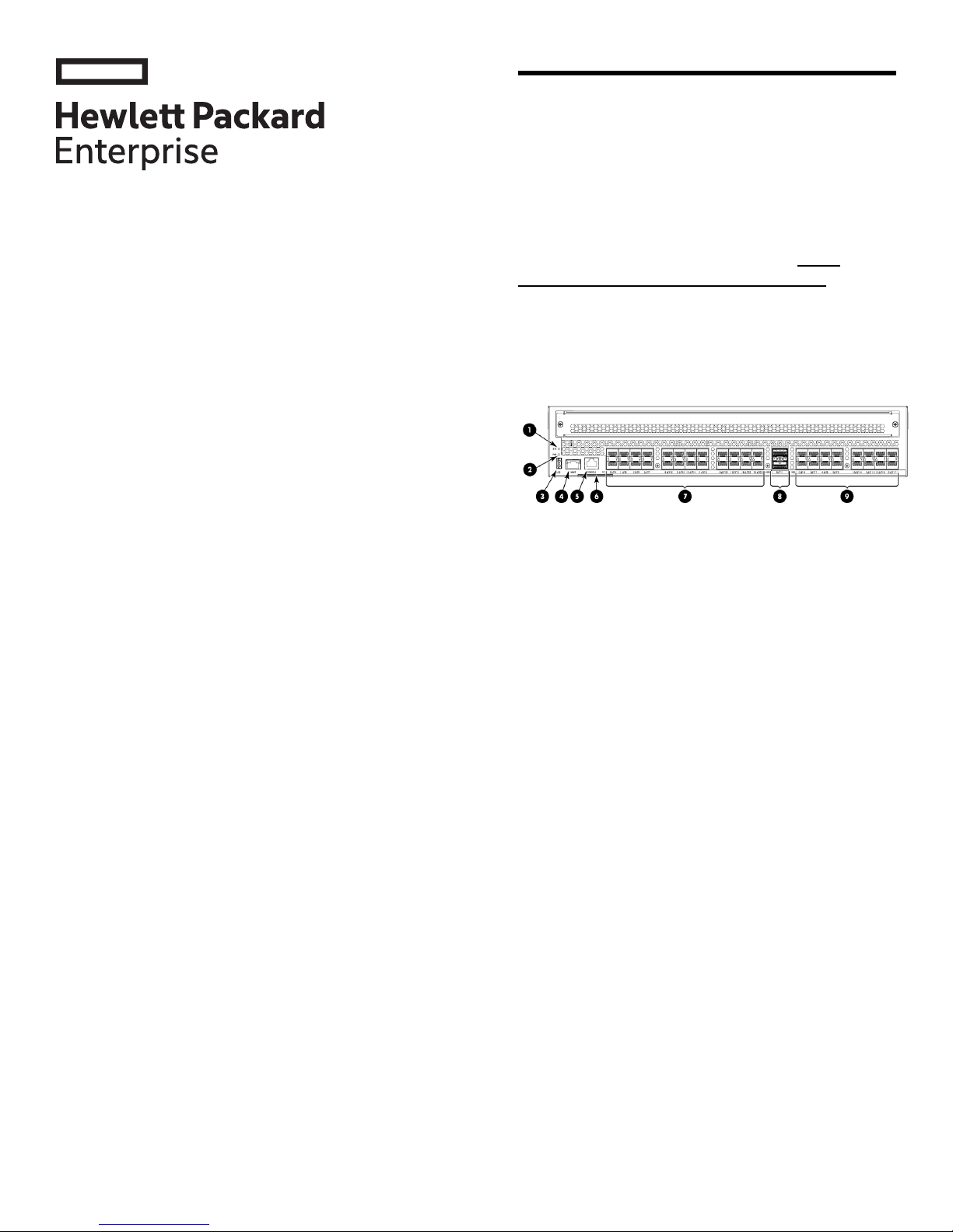
Figure 1 (page 1) shows the port side of the
SN4000B SAN Extension Switch.
Figure 1 Port side of the SN4000B SAN
Extension Switch
2. Power status LED1. System status LED
4. Ethernet management port3. USB port
6. Serial number pull-out tab5. Console port (RJ-45)
8. 40 GbE ports (QSFP+) (2)7. 16 Gb FC ports (24)
9. 1/10 GbE ports (16)
© Copyright 2015, 2016 Hewlett Packard Enterprise Development LP
The information contained herein is subject to change without notice.
The only warranties for Hewlett Packard Enterprise products and
services are set forth in the express warranty statements accompanying
such products and services. Nothing herein should be construed as
constituting an additional warranty. Hewlett Packard Enterprise shall
not be liable for technical or editorial errors or omissions contained
herein.
Part Number: 5200-0340
Published: January 2016
Edition: 2
*5200-0340*
Verify the carton contents
Verify that the carton contains the following:
• One StoreFabric SN4000B SAN Extension
Switch with two integrated power supply/fan
assemblies
• Serial cable with an RJ-45 connector
• An RJ-45 to DB-9 adapter
• Rubber feet, required to set up the switch as
a standalone unit
• Brocade EZ switch and China RoHs
documentation
• Two power cords
• One accessory kit with the following items:
Rack Mount Kit◦
◦ Hewlett Packard Enterprise product
documentation, including Read Me First,
Quick Start Instructions, Safety Guides,
HPE SAN Visibility CD, User License, and
Warranty.
Page 2
Verifying the installation requirements
To set up the SN4000B SAN Extension switch for
the first time, you will need the following:
rack. In this installation, the port side of the device
is set back from the edge of the rack, allowing a
more gradual bend in the fiber optic cables.
The following items are required to install the device
in a rack:
• Workstation with an installed terminal emulator
(such as HyperTerminal)
• Unused IP address and corresponding subnet
mask and gateway address
• Serial cable (supplied with the switch)
• Ethernet cable
• Access to an FTP server, SCP server, or USB
device for backing up the switch configuration
(optional)
• SFP transceivers and cables
Planning the site environment
To ensure adequate cooling, install the switch with
the non-port side (which contains the air intake
vents) facing the cool-air aisle. Verify that the
ambient air temperature does not exceed 40°C
(104°F) and that the ambient humidity remains
between 20% and 85% while the switch is
operating.
To install and operate the switch successfully,
ensure that:
• The primary AC input is 100–240 VAC, 50–60
Hz. The switch autosenses the input voltage.
• The primary outlet is wired correctly, protected
by a circuit breaker, and grounded in
accordance with local electrical codes.
• Power cables
• #2 Phillips screwdriver
• SAN Switch Rack Mount Kit hardware
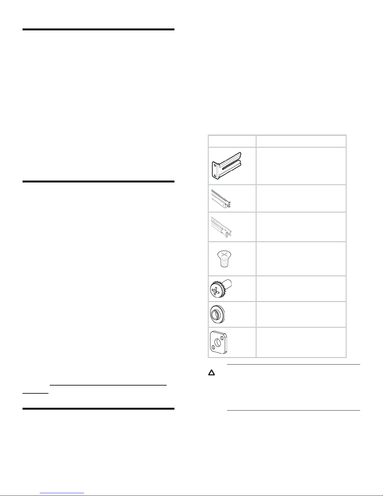
Table 1 (page 2) identifies the rails and
rail-mounting hardware.
Table 1 SAN Switch Rack Mount Kit hardware
DescriptionItem
Two rear mounting brackets
A right inner rail and a right outer
rail
A left inner rail and a left outer rail
Sixteen #8-32 x 5/16-inch Phillips
flathead SEMS screws
Twelve #10-32 x 1/2-inch Phillips
panhead screws with captive star
lock washers
Eight #10 alignment washers
• The supply circuit, line fusing, and wire size
are adequate, as specified by the electrical
rating on the switch nameplate.
For additional power supply information, see the
B-series 16Gb FC Switches Hardware Reference
Guide available on the Hewlett Packard Enterprise
website: http://www.hpe.com/support/sn4000b/
manuals.
Installing the switch in a rack using the
Rack Mount Kit
For optimal cable management, Hewlett Packard
Enterprise recommends that you install the SAN
Switch Rack Mount Kit to allow the nonport side of
the device to slide out of the cool-air side of the
Eight #10 adapter washers
CAUTION: For proper air flow, the SFP+
media side of the device port side must face
the rear of the rack. This allows cool air to
enter the front of the rack and exit from the
rear.
To install the device in a rack:
1. Verify that the required parts and hardware are
available (see Table 1 (page 2)).
2. Choose a mounting location for the device in
the rack.
Page 3
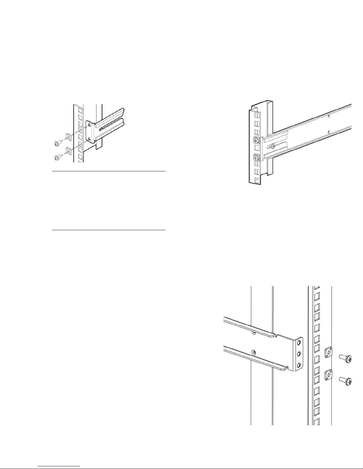
3. Attach the rear mounting brackets to the rear
rack uprights.
• Assemble each of the brackets using two
#10-32 x 1/2-inch Phillips panhead screws
with captive star lock washers and two
#10 adapter washers, as shown in
Figure 2 (page 3).
4. Assemble the outer rails as follows:
a. Attach the left outer rail and right outer rail
to the rear mounting brackets using the
#10-32 x 1/2-inch Phillips panhead screws
with captive star lock washers, as shown
in Figure 3 (page 3).Four screws are
required for attaching the outer rails.
Figure 2 Installing the rear mounting
brackets
NOTE: The SAN Switch Rack Mount
Kit contains outer rails labeled Left and
Right to designate the left side and right
side of the device or cabinet as viewed
from the front of the cabinet. The inner
rails are interchangeable and can be
used on either side of the switch.
Figure 3 Installing the outer rails
b. Install two #10-32 x 1/2-inch Phillips
panhead screws with captive star lock
washers and two #10 adapter washers in
the upper and lower holes on the right rail.
Then install two #10-32 x 1/2-inch Phillips
panhead screws with captive star lock
washers and two #10 adapter washers in
the upper and lower holes on the left rail
(see Figure 4 (page 3)).
Figure 4 Assembling the outer rails
Page 4
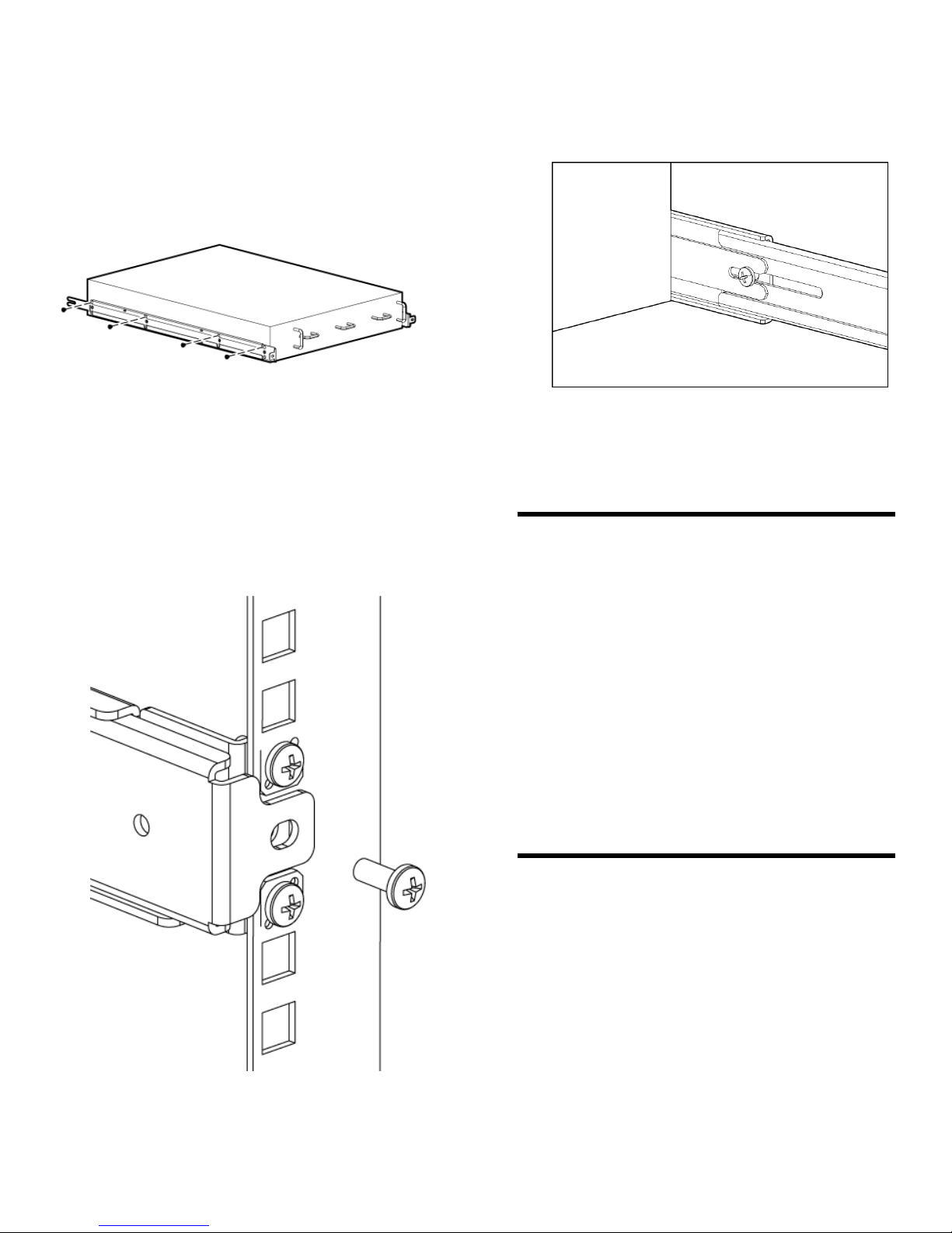
5. Use the screw type #8-32 x 5/16-inch (in the
screw holes marked 16) to attach the two inner
rails to the switch. Eight screws are required
for each rail.
Figure 5 (page 4) shows how the inner rails are
attached to the switch.
Figure 5 Inner rails attachment
and secure to the outer rail. Repeat for the
other side. See Figure 7 (page 4).
Figure 7 Securing the front of the switch to
outer rails
Securing the device to the outer rails
1. Insert the device with the attached inner rails
to the outer rails.
2. Insert the device into the rack and install one
#10-32 x 1/2-inch Phillips panhead screw with
captive star lock washer. Repeat for the other
side. See Figure 6 (page 4).
Figure 6 Securing the device
4. Tighten the screws installed in Figure 3 (page
3).
This completes the rack mount procedure.
Installing a standalone switch
1. Unpack the switch and verify the contents as
described in “Verify the carton contents”
(page 1).
2. Apply the adhesive rubber feet to prevent the
switch from sliding off the supporting surface.
a. Clean the indentations at each corner on
the bottom of the switch to ensure that
they are free of dust or other debris.
b. With the adhesive side against the
chassis, place one rubber foot in each
indentation and press into place.
3. Place the switch on a flat, sturdy surface.
3. Install one #10-32 x 1/2-inch Phillips panhead
screw with captive star washer through the
front of the inner rail, through the rear bracket,
Initial switch configuration
To configure the switch, you will need the following:
• Standard screwdriver
• If you are using static IP addressing, you will
need the following items (not required if you
are using DHCP (Dynamic Host Configuration
Protocol)):
◦ Fixed IP address (IPv4 or IPv6) for the
switch
◦ Subnet mask value
◦ Default gateway value
Page 5

• Ethernet connection (hub or switch)
• Ethernet and Fibre Channel cables
• Disk array with Fibre Channel ports
Power on the switch
To power on the switch:
1. Connect the power cords to both power
supplies and then to power sources on
separate circuits to protect against AC failure.
Ensure that the cords have a minimum service
loop of 15.24 cm (6 in) available and are routed
to avoid stress.
2. Power on the power supplies by flipping both
AC switches to the "|" position.
The power supply LEDs are amber until POST
is complete, and then change to green. The
SN4000B SAN Extension Switch takes several
minutes to boot and complete POST.
3. After POST is complete, verify that the switch
power and status LEDs on the port side of the
switch are green.
2. When the terminal emulator stops reporting
information, press Enter to display the login
prompt.
3. Log in to the switch as admin, using the default
password, password.
You are prompted to change the default
password at initial login.
Set the switch IP address
To set the switch IP address, you can either use a
static IP address or a DHCP server to set the IP
address. DHCP is enabled by default.
Setting the IP address using DHCP
When using DHCP, the switch obtains its IP
address, subnet mask, and default gateway address
from the DHCP server. The DHCP client can only
connect to a DHCP server that is on the same
subnet as that of the switch. If your DHCP server
is not on the same subnet as that of the switch, use
a static IP address.
Setting a static IP address
Connect the serial cable
1. Connect the serial cable to the RJ-45 serial
port on the switch and to the serial port on the
workstation.
2. Disable any serial communication programs
running on the workstation.
3. Open a terminal emulator (such as
HyperTerminal on a PC, or TERM, TIP, or
Kermit in a UNIX environment) and configure
the application as follows:
For most Windows systems:
Bits per second: 9,600
Data bits: 8
Parity: None
Stop bits: 1
Flow control: None
For most UNIX systems:
tip /dev/ttyb -9600
If ttyb is already in use, try ttya instead:
tip /dev/ttya -9600
Log in to the serial console port
1. Verify that the switch has completed POST.
When POST is complete, the port status,
switch power, and status LEDs return to a
normal state.
1. Use the ipaddrset command to set the
Ethernet IP address.
• For an IPv4 address, use dotted-decimal
notation:
Ethernet IP Address:
192.168.74.102
• For an IPv6 address, use colon-separated
notation:
switch:admin> ipaddrset -ipv6
--add 1080::8:800:200C:417A/64
2. Provide the remaining network information:
Ethernet Subnetmask: 255.255.255.0
Ethernet IP Address: 192.168.74.102
Ethernet Subnetmask: 255.255.255.0
Ethernet IP Address: 192.168.74.102 Ethernet
Subnet mask: 255.255.252.0 Gateway IP
Address: 15.226.172.1
When prompted, enter off to disable DHCP:
DHCP [OFF]: off
The following message confirms the change:
IP address is being changed...Done.
3. Optional: Verify the IP address by entering the
ipaddrshow command at the prompt.
4. Record the IP address on the pull-out tab on
the port side of the switch.
Page 6

5. If the serial port is no longer required, use the
logout command to log out of the serial
console. Remove the serial cable and replace
the plug in the serial port.
6. Connect the Ethernet port on the switch to the
Ethernet network that assigned the IP address.
Set the date and time
The date and time settings are used for logging,
error detection, and troubleshooting.
1. Using a Telnet or Secure Shell session,
connect to the switch using the IP address that
you configured, and then log in to the switch
as admin using the password you set when
you logged in to the serial console port.
2. Enter the date command using the following
syntax:
date "mmddHHMMyy", where:
4. Enter the tsclockserver command to
synchronize local time using NTP:
switch:admin> tsclockserver
“<ntp1;ntp2>”
The value of ntp1 is the IP address or DNS
name of the first NTP server, which the switch
must be able to access. The value of ntp2 is
the second NTP server and is optional. When
multiple NTP server addresses are specified,
tsclockserver sets the first obtainable
address as the active NTP server. The default
value is LOCL.
switch:admin> tsclockserver
LOCL
switch:admin> tsclockserver "132.163.135.131"
switch:admin> tsclockserver
132.163.135.131
switch:admin>
mm is the month; valid values are 01 through
12.
dd is the date; valid values are 01 through 31.
HH is the hour; valid values are 00 through 23.
MM is minutes; valid values are 00 through 59.
yy is the year; valid values are 00 through 99.
NOTE: Year values greater than 69
are interpreted as 1970 through 1999,
whereas year values less than 70 are
interpreted as 2000 through 2069.
3. Enter the tstimezone command:
switch:admin> tstimezone
[--interactive]/ [, timezone_fmt]
Use timezone_fmt to set the time zone by
country/city or by time-zone ID, such as PST.
The following example shows how to change
the time zone to US/Central:
switch:admin> tstimezone
Time Zone : US/Pacific
switch:admin> tstimezone US/Central
switch:admin> tstimezone
Time Zone : US/Central
Switch setup
Connect devices
For information on connecting devices, zoning, and
advanced configuration tasks, see the Brocade
Fabric OS FCIP Administrator's Guide and the
Brocade Fabric OS administrator's guide supporting
FOS 7.3.0 or later on the Hewlett Packard
Enterprise website: http://www.hpe.com/support/
sn4000b/manuals.
Verifying switch operation
To verify switch operation:
1. Check the LEDs to verify that all components
are functional. For information about LED
patterns, see the B-series 16Gb Switches
Hardware Reference Guide.
2. Verify the correct operation of the switch by
issuing the switchShow command.
This command provides information about
switch and port status.
3. Verify the correct operation of the fabric by
issuing the fabricShow command.
This command provides general information
about the fabric.
4. Back up the switch configuration to an FTP
server by issuing the configUpload
command and following the prompts.
This command uploads the switch configuration
to the server, making it available for
downloading to a replacement switch if
necessary.
Page 7

Setting the switch features
This completes the initial setup of your StoreFabric
SN4000B SAN Extension Switch. For detailed
instructions on setting all the supported switch
features, see the Fabric OS 7.3.x FCIP
Administrator's Guide,Fabric OS 7.3.x
administrator's guide and the Fabric OS 7.3.x
Command reference manual on the Hewlett
Packard Enterprise website: http://www.hpe.com/
support/sn4000b/manuals.
 Loading...