

Page 1

HP StorageWorks
XP24000/XP20000 Remote Web Console
User Guide
Abstract
This guide explains how to set up and use HP StorageWorks Remote Web Console to manage HP StorageWorks
XP24000/XP20000 Disk Arrays over a LAN connection. Topics include how to obtain storage system configuration and status
information, send user-requested commands to the storage system, install and launch XP program products, and troubleshoot
storage system issues. The intended audience is a storage system administrator or authorized service provider with independent
knowledge of XP storage systems.
HP Part Number: AE131-96087
Published: May 2011
Edition: Fifteenth
Page 2

© Copyright 2007, 2011 Hewlett-Packard Development Company, L.P.
Confidential computer software. Valid license from HP required for possession, use or copying. Consistent with FAR 12.211 and 12.212, Commercial
Computer Software, Computer Software Documentation, and Technical Data for Commercial Items are licensed to the U.S. Government under
vendor's standard commercial license.
The information contained herein is subject to change without notice. The only warranties for HP products and services are set forth in the express
warranty statements accompanying such products and services. Nothing herein should be construed as constituting an additional warranty. HP shall
not be liable for technical or editorial errors or omissions contained herein.
Acknowledgments
Microsoft, Windows, and Windows XP are U.S. registered trademarks of Microsoft Corporation.
Java is a U.S. trademark of Sun Microsystems, Inc.
UNIX is a registered trademark of The Open Group.
Hitachi and Universal Replicator are registered trademarks of Hitachi, Ltd.
ShadowImage and TrueCopy are registered trademarks of Hitachi, Ltd. and Hitachi Data Systems Corporation.
Export Requirements
You may not export or re-export this document or any copy or adaptation in violation of export laws or regulations.
Without limiting the foregoing, this document may not be exported, re-exported, transferred or downloaded to or within (or to a national resident
of) countries under U.S. economic embargo, including Cuba, Iran, North Korea, Sudan, and Syria. This list is subject to change.
This document may not be exported, re-exported, transferred, or downloaded to persons or entities listed on the U.S. Department of Commerce
Denied Persons List, Entity List of proliferation concern or on any U.S. Treasury Department Designated Nationals exclusion list, or to parties directly
or indirectly involved in the development or production of nuclear, chemical, biological weapons, or in missile technology programs as specified
in the U.S. Export Administration Regulations (15 CFR 744).
Revision History
DescriptionDateEdition
This edition applies to microcode version 60-01-31-00/00 or later.June 2007First
This edition applies to microcode version 60-01-68-00/00 or later.September 2007Second
This edition applies to microcode version 60-02-03-00/00 or later.November 2007Third
This edition applies to microcode version 60-02-25–00/00 or later.January 2008Fourth
This edition applies to microcode version 60-02-48-00/00 or later.April 2008Fifth
This edition applies to microcode version 60-03-04-00/00 or later.June 2008Sixth
This edition applies to microcode version 60-03-24-00/00 or later.September 2008Seventh
This edition applies to microcode version 60-04-04-00/00 or later.December 2008Eighth
This edition applies to microcode version 60-04-13-00/00 or later.February 2009Ninth
This edition applies to microcode version 60-04-13-00/00 or later.April 2009Tenth
This edition applies to microcode version 60-05-00-00/00 or later.June 2009Eleventh
This edition applies to microcode version 60-06-05-00/00 or later.December 2009Twelfth
This edition applies to microcode version 60-07-00-00/00 or later.June 2010Thirteenth
This edition applies to microcode version 60-07-50-00/00 or later.October 2010Fourteenth
This edition applies to microcode version 60-08-00-00/00 or laterMay 2011Fifteenth
Page 3

Contents
1 About Remote Web Console Operations.......................................................7
Overview of Remote Web Console.............................................................................................7
Remote Web Console GUI....................................................................................................7
CFL Extension......................................................................................................................8
Remote Web Console Features...................................................................................................8
User Access Levels....................................................................................................................9
User Types..........................................................................................................................9
Operation Privileges...........................................................................................................10
Overview of Audit Logs...........................................................................................................12
Overview of Configuration File Loader Operations......................................................................13
Overview of SSL-Encrypted Communications...............................................................................14
Encryption Function Enhancement (Solution to the Year 2010 Encryption Problem)...........................14
The Year 2010 Encryption Problem.......................................................................................15
Single Sign-on from HP Systems Insight Manager........................................................................15
Important Terms and Concepts.................................................................................................16
2 Installation Requirements and Procedures.....................................................18
System Requirements...............................................................................................................18
Requirements for Windows..................................................................................................18
Requirements for UNIX........................................................................................................21
Setting Up Remote Web Console..............................................................................................22
Configuring the Web Browser..............................................................................................22
Configuring Remote Web Console over a Firewall..................................................................23
Configuring Java...............................................................................................................23
JRE 1.4........................................................................................................................23
JRE 5.0 or JRE 6.0.........................................................................................................24
Configuring Communications over only IPv6..........................................................................27
Remote Web Console Conventions............................................................................................29
General Parameters............................................................................................................29
Keystrokes and Navigation..................................................................................................30
UNIX................................................................................................................................31
Windows Server 2003/2008 Initial Setup............................................................................32
Starting Up and Logging In to Remote Web Console...................................................................34
Overview of Login Procedures.............................................................................................35
Permission for Accessing Local Client Files.............................................................................36
Logging In to a Storage System............................................................................................38
Using SSL-Encrypted Communication................................................................................39
Using Windows Server 2003/2008................................................................................41
Changing Between View Mode and Modify Mode................................................................41
Extending the Modify Mode Timeout Period..........................................................................42
License Keys...........................................................................................................................43
Temporary Key..................................................................................................................43
Permanent Key...................................................................................................................44
Term Key..........................................................................................................................44
Emergency Key..................................................................................................................45
Licensed Capacity..................................................................................................................45
Estimating Licensed Capacity Based on Used Capacity...........................................................46
Estimating Licensed Capacity Based on Mounted Capacity......................................................47
Remote Web Console Options and Licensed Capacity............................................................47
Contents 3
Page 4

3 Using the Remote Web Console GUI...........................................................50
Common Elements of the Remote Web Console Main Windows...................................................50
File Menu.........................................................................................................................52
Go Menu..........................................................................................................................53
Help Menu.......................................................................................................................54
Icons................................................................................................................................55
License Key Window...............................................................................................................56
License Key List..................................................................................................................58
License Install Box..............................................................................................................60
License Status Box..............................................................................................................61
Identity Window.....................................................................................................................61
Device Information.............................................................................................................62
LDEV Information...............................................................................................................63
Number of LDEVs..............................................................................................................65
Port Status Window................................................................................................................66
Alerts Window.......................................................................................................................67
Detail Dialog Box..............................................................................................................69
Account Window...................................................................................................................70
Login Message Window..........................................................................................................71
Syslog Window......................................................................................................................72
Audit Log Transfer Window......................................................................................................74
Audit Log Setting Window.......................................................................................................76
Encryption Window................................................................................................................77
E-mail Information Window......................................................................................................77
Configuration File Loader Window............................................................................................79
Reports Display Dialog Boxes...................................................................................................81
Common Elements.............................................................................................................81
Port Dialog Box.................................................................................................................82
LUN Dialog Box.................................................................................................................84
LDEV Dialog Box...............................................................................................................85
LDEV Status Dialog Box......................................................................................................87
XP Thin Provisioning Dialog Box...........................................................................................89
Connected Host Dialog Box................................................................................................89
Detail Information Dialog Box..............................................................................................90
Tool Panel..............................................................................................................................91
Control Panel.........................................................................................................................92
Set Env. Dialog Box............................................................................................................92
Download Dialog Box........................................................................................................94
Restore Dialog Box.............................................................................................................95
4 Performing Remote Web Console Operations...............................................97
Enabling and Disabling Remote Web Console Options...............................................................97
Enabling Options Using a License Key Code.........................................................................97
Enabling Options Using a License Key File............................................................................98
Enabling Options Automatically...........................................................................................99
Enabling or Disabling a License...........................................................................................99
Disabling Remote Web Console Options............................................................................100
Launching the Desired Option................................................................................................100
Managing the User Accounts.................................................................................................101
Registering New Users......................................................................................................101
Changing User Passwords.................................................................................................102
Changing User Operation Privileges...................................................................................103
Enabling or Disabling User Accounts..................................................................................103
Deleting Users.................................................................................................................104
4 Contents
Page 5

Reporting SIMs by Email........................................................................................................104
Configuring Settings for Email Notice.................................................................................104
Sending a Test Email........................................................................................................105
Setting the Environment Parameters.........................................................................................106
Downloading the Configuration Files.......................................................................................106
Restoring Backups of the Configuration Files.............................................................................107
Downloading Trace Files Using the FD Dump Tool.....................................................................110
Using Configuration File Loader..............................................................................................111
Exporting a Spreadsheet...................................................................................................112
Editing the Spreadsheet....................................................................................................112
Importing the Spreadsheet................................................................................................114
Registering and Deleting the Certificates of HP Systems Insight Manager......................................115
Importing a Tool Definition File into HP Systems Insight Manager............................................115
Registering the Certificates of HP Systems Insight Manager....................................................116
Deleting the Certificates of HP Systems Insight Manager........................................................117
5 Using the CFL Extension..........................................................................119
Overview of the CFL Extension...............................................................................................119
CFL Extension Operations......................................................................................................119
Preparing for Using CFL Extension..........................................................................................120
Requirements for CFL Extension..........................................................................................121
Installing CFL Extension.....................................................................................................121
Installing JRE with Support for Additional Languages............................................................121
Changing the Java Security Policy......................................................................................122
Creating a User Authentication File....................................................................................122
Modifying a Batch File.....................................................................................................123
Notes on Using CFL Extension...........................................................................................124
Command Reference.............................................................................................................124
CFLCHK Command..........................................................................................................125
CFLGET Command...........................................................................................................125
CFLSET Command...........................................................................................................126
Spreadsheets.......................................................................................................................127
Spreadsheet File Conventions............................................................................................127
Spreadsheet Components.................................................................................................128
Declaration................................................................................................................128
Operation Tags...............................................................................................................128
Parameters......................................................................................................................129
Comments.......................................................................................................................129
Common Operation Tags..................................................................................................129
SerialNumber Tag.......................................................................................................129
Execution Results..............................................................................................................130
6 Troubleshooting......................................................................................132
General Troubleshooting........................................................................................................132
General Error Conditions and Recommended Actions...........................................................132
CFL Extension Error Conditions and Recommended Actions...................................................137
Clearing Cache of Java and Web Browsers.........................................................................138
Calling HP Technical Support.................................................................................................138
7 Support and Other Resources...................................................................139
Related Documentation..........................................................................................................139
Conventions for Storage Capacity Values.................................................................................140
HP Technical Support............................................................................................................140
Contents 5
Page 6

Subscription Service..............................................................................................................140
HP Websites........................................................................................................................140
Documentation Feedback.......................................................................................................141
A Audit Logs for Single Sign-On..................................................................142
BASE Function – Certificate Import Operation...........................................................................142
BASE Function – Delete Certificate Operation...........................................................................142
BASE Function – Login Operation............................................................................................143
BASE Function – SSO Authentication Operation........................................................................143
BASE Function – SSO SetOneTimeKey Operation......................................................................143
B Error Codes for Single Sign-On................................................................145
Glossary..................................................................................................146
Index.......................................................................................................148
6 Contents
Page 7

1 About Remote Web Console Operations
This chapter provides an overview of Remote Web Console functions.
• “Overview of Remote Web Console” (page 7)
• “Remote Web Console Features” (page 8)
• “User Access Levels” (page 9)
• “Overview of Audit Logs” (page 12)
• “Overview of Configuration File Loader Operations” (page 13)
• “Overview of SSL-Encrypted Communications” (page 14)
• “Important Terms and Concepts” (page 16)
Unless otherwise specified, the term storage system in this guide refers to the following disk arrays:
• HP StorageWorks XP24000 Disk Array
• HP StorageWorks XP20000 Disk Array
The GUI illustrations in this guide were created using a Windows computer with the Internet Explorer
browser. Actual windows may differ depending on the operating system and browser used. GUI
contents also vary with licensed program products, storage system models, and firmware versions.
Overview of Remote Web Console
Remote Web Console enables you to remotely manage the storage system. This section describes
how Remote Web Console accesses the storage system.
The storage system has a computer called an SVP that is used for maintenance. Remote Web
Console accesses the SVP to obtain storage system configuration and status information and to
send user-requested commands to the storage system. Remote Web Console consists of a group
of applications that run on the JVM. The SVP uses JVM to function as a web server and Remote
Web Console to function as a Java client. The Java client that runs Remote Web Console is called
a Remote Web Console computer.
Remote Web Console communicates with SVPs on the storage systems via a LAN. The supported
interfaces between Remote Web Console and the SVP are GUI and CFL Extension.
Remote Web Console GUI
The Remote Web Console GUI allows you to perform operations on the storage system using the
Remote Web Console windows that are displayed in a web browser.
The storage system can be connected to two LANs. The storage system internal LAN is a private
LAN that is used to connect the SVPs of multiple storage systems. Your intranet is a public LAN
that allows you to access one or more SVPs from individual Remote Web Console computers. This
configuration allows you to easily access and control the registered storage system.
Figure 1 (page 8) shows an example of Remote Web Console computer and SVP configuration.
Overview of Remote Web Console 7
Page 8
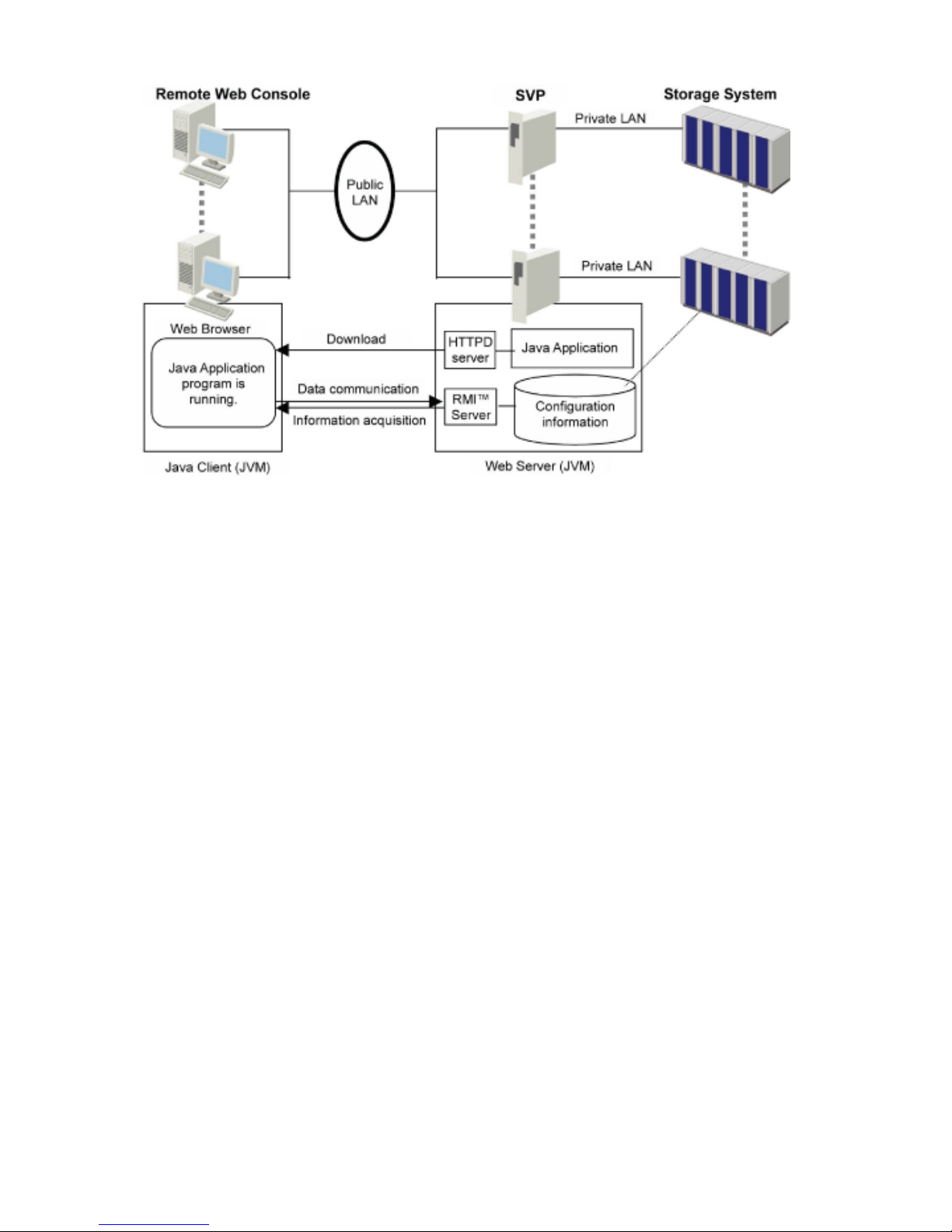
Figure 1 Example of Remote Web Console Computer and SVP Configuration
CFL Extension
The CFL Extension allows you to perform commands on the storage system using the command
prompt. To use the CFL Extension, you need to install certain files on the Remote Web Console
computer.
The current version of the CFL Extension can be used to perform only specific operations of specific
program products. For details on the CFL Extension, see “Using the CFL Extension” (page 119).
Remote Web Console Features
Remote Web Console enables you to perform the following operations:
• View the storage system information
You can view storage system and LDEV information in the Identity window (see “Identity
Window” (page 61)).
◦
◦ You can view the mounted status of ports in the Port Status window (see “Port Status
Window” (page 66)).
◦ You can view specific LUN, LDEV, and port values in the Reports Display dialog box,
which is different from the Remote Web Console main window (see “Reports Display
Dialog Boxes” (page 81)).
• Use program product options and functions
You can use program product options remotely on the storage system.
See the appropriate user's guide for details about storage system options. For installation
instructions, see “Enabling and Disabling Remote Web Console Options” (page 97). For
launch instructions, see “Launching the Desired Option” (page 100).
◦
◦ You can save the settings of some program product options to a spreadsheet file, or you
can specify multiple settings all together in a spreadsheet file (see “Overview of
Configuration File Loader Operations” (page 13)).
8 About Remote Web Console Operations
Page 9

◦ You can specify SNMP agent properties remotely to the SVP (see the HP StorageWorks
XP24000/XP20000 SNMP Agent Reference Guide).
◦ You can virtually partition built-in cache memory or storage (see the HP StorageWorks
XP24000/XP20000 Disk/Cache Partition User Guide).
• Consider security
You can register user accounts for Remote Web Console and specify the operation
privileges for each account (see “User Access Levels” (page 9)).
◦
◦ You can check the current number of user accounts and set the timeout period with the
Remote Web Console environment parameters (see “Set Env. Dialog Box” (page 92)).
◦ You can display a warning message to unauthorized access on the Remote Web Console
login window (see “Login Message Window” (page 71)).
◦ You can view the audit logs that list the user's login history (see “Overview of Audit Logs”
(page 12)).
◦ You can encrypt communication between the Remote Web Console and the SVP (see
“Overview of SSL-Encrypted Communications” (page 14)).
• Gather necessary information for troubleshooting
You can view the error history of the storage system (see “Alerts Window” (page 67)).◦
◦ You can automate email notification of storage system failures (see “E-mail Information
Window” (page 77)).
◦ You can download trace files (see “Downloading Trace Files Using the FD Dump Tool”
(page 110)).
◦ You can back up and restore the setting information for Remote Web Console (see
“Download Dialog Box” (page 94) and “Restore Dialog Box” (page 95)).
User Access Levels
To use Remote Web Console, you first need to set up a user account. Remote Web Console user
account contains the following information:
• User ID
• User type
• Password
• Operation privileges
For Remote Web Console, a user account with a user ID of administrator is initially set. By default,
operation privileges for all functions of Remote Web Console and program product options are
given to the administrator user account. You cannot delete the administrator user account. You
may register up to 500 user accounts, including the administrator account, for Remote Web
Console.
You have to set user ID, user type, and password when you set up a user account. Operation
privileges can be set for each registered user account. To register the user account or to set operation
privileges, use the Account window. For further information on the procedures for registering a
user account and setting operation privileges for Remote Web Console, see “Account Window”
(page 70).
The following sections describe user types and operation privileges.
User Types
Remote Web Console provides two types of user access levels: storage administrator and storage
partition administrator. You decide the user type when you register a user account.
User Access Levels 9
Page 10

The range of operating privileges varies by user type:
• Storage administrator
A storage administrator can operate the entire storage system. The administrator user account,
which is the default Remote Web Console user account, is a kind of storage administrator.
Only the storage administrator can perform the following:
◦ Use the Control Panel
◦ Perform audit log and syslog-related operations
◦ Execute the CFL Extension commands
◦ Use the FD dump tool
• Storage partition administrator
A storage partition administrator can operate an SLPR allocated by Remote Web Console. A
storage partition administrator can manipulate user accounts and perform operations using
some (not all) program products. For further information on SLPR or details on the program
products that a storage partition administrator can use, see “Go Menu” (page 53).
Operation Privileges
As you set the user ID and password when you register a user, you can also set various types of
operation privileges for the registered user account. In Remote Web Console, the operation privilege
might be called a role.
The following roles can be assigned to user accounts:
• Account Administrator role. This role has user account operation privileges. Specify Modify,
View, or Disable for each user account. The Modify privilege is set for the administrator user
account, and this privilege cannot be changed.
Table 1 (page 10) shows the operations available to the Account Administrator role.
Table 1 Operations Available to the Account Administrator Role
Account Administrator RoleOperations
DisableViewModify
Not AvailableNot AvailableAvailableAdding, deleting, and changing user
accounts
Not AvailableAvailableAvailableViewing the setting of user accounts of other
users
Not AvailableNot AvailableAvailableChanging the password of other users
AvailableAvailableAvailableViewing the setting of the user account of
the user
AvailableAvailableAvailableChanging the password of the user
AvailableAvailableAvailableViewing the setting of the user account of
the user
AvailableAvailableAvailableChanging the user password
Not AvailableNot Available
(Viewing is allowed)
AvailableEditing the content in the Login Message
window
1
1 A storage partition administrator cannot perform the operation even if the storage partition administrator has the
appropriate operation privileges.
• Audit Log Administrator role. This role has audit log operation privileges and can perform
audit log and syslog-related operations. Specify Modify, View, or Disable for the user account
10 About Remote Web Console Operations
Page 11

of a storage administrator. The Modify privilege is set for the administrator user account. The
Disable privilege is set for a Storage Partition Administrator, and this privilege cannot be
changed.
Table 2 (page 11) shows the operation privileges and operations that can be performed for
the Audit Log Administrator role.
Table 2 Operations Available to the Audit Log Administrator Role
Audit Log Administrator RoleOperations
DisableViewModify
Not AvailableAvailableAvailableDownloading audit log using the button on
upper part of the Remote Web Console main
window
Not AvailableAvailableAvailableDownloading syslog using the Syslog
window
Not AvailableAvailableAvailableViewing the Syslog window, the Audit Log
Transfer window, and the Audit Log Setting
window
Not AvailableNot AvailableAvailableChanging the setting for transferring audit
log and syslog on the Audit Log Transfer
window and the Syslog window
Not AvailableNot AvailableAvailableManually transferring audit log using the
Audit Log Transfer window
Not AvailableNot AvailableAvailableConfiguring the audit log settings using the
Audit Log Setting window
Not AvailableAvailableAvailableDownloading the audit log transfer
information using Control Panel
Not AvailableNot AvailableAvailableRestoring the audit log transfer information
using Control Panel
• Encryption Administrator role. This role has the operation privilege to encrypt data stored in
volumes in the storage system. Specify the Enable or Disable privilege for the user account of
a storage administrator. The Enable privilege is set for the administrator user account. The
User Access Levels 11
Page 12

Disable privilege is set for a Storage Partition Administrator, and this privilege cannot be
changed.
A storage administrator with the Enable privilege can do the following:
◦ Perform data encryption operations using the VLL window. See the HP StorageWorks
XP24000/XP20000 Virtual LVI/LUN (VLL) and Volume Shredder User Guide.
◦ Back up and restore the encryption key using the Encryption window. See the HP
StorageWorks XP24000/XP20000 Disk Encryption User Guide.
• Storage Administrator role. This role has storage operation privileges. Specify either Enable
or Disable for each user account. The Enable privilege is set for the administrator user account.
The administrator user account has Modify privileges for the operations of all program products.
A storage administrator with the Enable privilege can do the following; however, a storage
partition administrator with the Enable privilege can perform only operations using some (not
all) program products:
◦ Perform operations using the Set Env. dialog box.
◦ Download and restore the environment parameter list.
◦ Perform operations using program products. Select either the Modify or View privilege
for each program product. Modify is required to perform operations using the program
product. For details on program products, see “Go Menu” (page 53).
Overview of Audit Logs
The Audit Log function allows you to record the access and configuration changes made to your
storage system. The audit log can be used to investigate when an incorrect setup is performed or
when a problem occurs in the storage system.
You can view the audit log by one of the following methods:
• Transferring the audit log to FTP servers
• Transferring the audit log to syslog servers
• Downloading the audit log to the Remote Web Console computer
You can download two files with different formats to the Remote Web Console computer. The file
that has the same format as the audit log transferred to syslog servers is called the syslog file. The
file that has the same format as the audit log transferred to FTP servers is called the audit log file.
Figure 2 (page 13) shows an overview of the audit log transfer operations.
12 About Remote Web Console Operations
Page 13
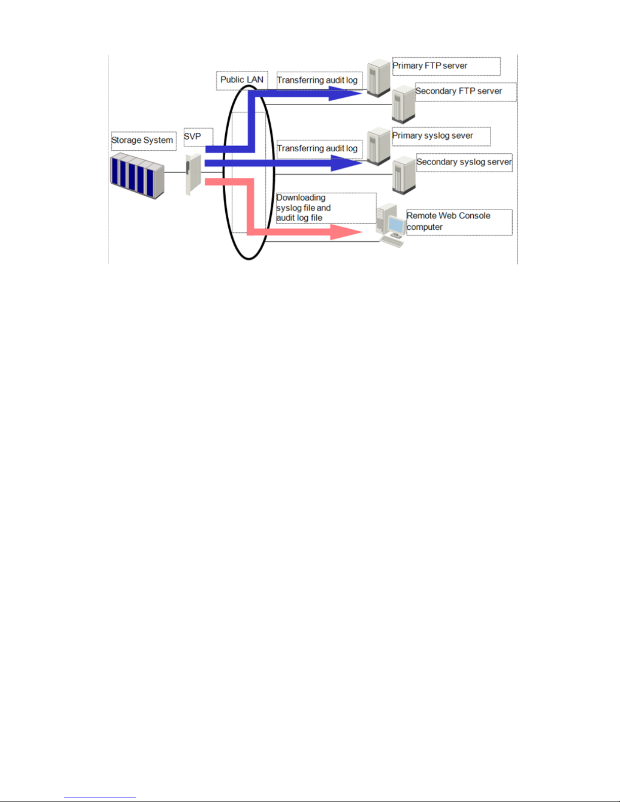
Figure 2 Overview of the Audit Log Transfer
You can transfer audit logs to FTP servers or syslog servers after connecting these servers through
the LAN to the SVP of the storage system. A maximum of two FTP servers and two syslog servers
can be connected to the SVP. The first one is named primary FTP server or primary syslog server.
The second one is named secondary FTP server or secondary syslog server.
The audit log is stored in the SVP. Older data in the file is deleted from the audit log file when the
number of lines of saved data reaches the maximum quantity.
• If you configure the FTP server settings, the audit log will be automatically transferred to the
FTP server when the number of lines in the file reaches the threshold.
• If you configure syslog server settings, the audit log will be always transferred to the syslog
server.
You can temporarily store the audit log on a system disk in a storage system before storing the log
in the SVP so that the unsaved audit log will not be lost. The audit log stored in the system disk will
be eventually stored in the SVP. If you need to keep track of commands sent from the host, HP
recommends that you temporarily store the audit log on a system disk before storing the logs in
the SVP.
To transfer the audit log to servers, configure server settings using the Syslog window or the Audit
Log Transfer window. To store the audit log on a system disk, configure the setting using the Audit
Log Setting window. See the HP StorageWorks XP24000/XP20000 Audit Log User and Reference
Guide to configure server settings in each window.
Overview of Configuration File Loader Operations
Configuration File Loader is used to make large-scale or batch changes to the configuration of
certain program product options, using either a text editor or spreadsheet software to edit
configuration definition files (spreadsheet files) and apply the changes to the storage system. You
can apply the same spreadsheet file to different storage systems, and you can define the
configuration in the spreadsheet when you are offline.
The process of applying a spreadsheet to the storage system differs depending on the program
products. Table 3 (page 14) shows program products supporting a spreadsheet and how to apply
a spreadsheet.
Overview of Configuration File Loader Operations 13
Page 14

Table 3 Program Products Supporting Spreadsheets and How to Apply a Spreadsheet
How to Apply a SpreadsheetProgram Products Supporting Spreadsheets
The Configuration File Loader windowLUN Manager
Volume Retention Manager
The CFL ExtensionLUN Expansion
Hitachi Universal Replicator™ for Mainframe
HP StorageWorks XP External Storage Software
For further information on these program product options, see the corresponding documents for
each program product.
Overview of SSL-Encrypted Communications
In order to improve security of remote operations from a Remote Web Console to a storage system,
you can set up SSL-encrypted communication. With SSL-encrypted communication, the user ID and
password required for logging in to the Remote Web Console are encrypted, and you can
communicate with a higher level of security.
For detailed information on the SSL-encrypted communication, contact your HP service representative.
You need to change the SVP (web server) to Apache, which supports SSL, in order to perform
SSL-encrypted communication. Your HP service representative will change the SVP to the
SSL-supported Apache.
Encryption Function Enhancement (Solution to the Year 2010 Encryption
Problem)
Remote Web Console and other SSL encrypted communication includes encryption processing
functionality.
The encryption functions are prepared for the year 2010 problem of encryption. This setting is
called Advanced Security Mode. If this setting is performed, the cryptographic algorithm changes
in some of the functions, but the Remote Web Console functions and operation methods are not
changed.
If you want to set the Advanced Security Mode, contact HP. See “HP Technical Support” (page 140).
If you set the Advanced Security Mode and use Remote Web Console, please note the following:
• When you enable the Advanced Security Mode, it might not be possible to connect to the SVP
from the P9000 or XP Command View Advanced Edition Software or some browsers for the
version that is not prepared for the year 2010 encryption problem.
• Confirm that all the devices that will be connected to the SVP are for the versions prepared
for the year 2010 encryption problem before enabling the Advanced Security Mode.
• If you enable the Advanced Security Mode, the user account is initialized where only root is
registered. It is necessary to recreate a user account.
• In the status where the Advanced Security Mode is enabled, the user list that was backed up
when the option was OFF, or in the previous version, (older than 60-07-50-00-/00) cannot
be used.
• If the account information update is performed while the Advanced Security Mode is enabled
and the version of the microprogram is downgraded to the previous version (older than
60-07-50-00-/00), the account information where the microcode is upgraded to the version
60-07-50-00-/00 or later again does not reflect the updated information of the previous
14 About Remote Web Console Operations
Page 15

version. If the Advanced Security Mode is enabled, do not perform the account update
operation on the version that was downgraded to the previous version.
• If the Advanced Security Mode is enabled, HP recommends using a certificate for the
SSL-encrypted communication with the hash function larger than SHA-2 (SHA-256 or larger).
The Year 2010 Encryption Problem
The National Institute of Standards and Technology (NIST) compiles the types of encryption that
U.S. government agencies should use. The NIST recommends transitioning to encryption types with
larger key size and advanced security after 2010. Although responding to this issue is not
mandatory, it is recommended. A large number of devices and systems utilizing encryption will
be affected by this new encryption standard.
Single Sign-on from HP Systems Insight Manager
Remote Web Console supports single sign-on from HP Systems Insight Manager. A user who logs
in to HP Systems Insight Manager can operate the Remote Web Console main window by clicking
Remote Web Console in the Tool menu of HP Systems Insight Manager. The user is not required to
enter a user ID and password into Remote Web Console, because the user is already logged in
to HP Systems Insight Manager. To implement single sign-on using HP Systems Insight Manager,
you need to import a Remote Web Console tool definition file into HP Systems Insight Manager,
and register certificates for HP Systems Insight Manager to the SVP. For details on how to import
a tool definition file, see “Importing a Tool Definition File into HP Systems Insight Manager”
(page 115). For details on how to register certificates, see “Registering the Certificates of HP Systems
Insight Manager” (page 116).
All users who are allowed to log in to HP Systems Insight Manager can also log in to Remote Web
Console. The operation privilege (role) for Remote Web Console depends on what kind of operation
privileges the user has when the user logs in to HP Systems Insight Manager (see Table 4 (page
15)).
Table 4 Operation Privileges for Remote Web Console after Single Sign-on from HP Systems Insight
Manager
Role for Remote Web ConsoleRole for HP Systems
Insight Manager
Operation privilege for
each function
1
Storage administrator
role
Audit log
administrator role
Account administrator
role
Modify (for all
functions)
EnableModifyModifyAdministrator
Modify (for all
functions)
EnableModifyDisableOperator
View (for all functions)EnableViewDisableUser
1 User accounts registered to HP Systems Insight Manager are not allowed to set the operation privilege for each function
of program product options.
Single Sign-on from HP Systems Insight Manager 15
Page 16

NOTE: User accounts registered to HP Systems Insight Manager are different from the user
accounts for Remote Web Console. To implement single sign-on, you do not need to register the
user accounts of HP Systems Insight Manager to Remote Web Console. If a user logs in with both
ways (to log in directly to Remote Web Console, and to log in with single sign-on from HP Systems
Insight Manager), make sure that the operation privilege of the user account registered to HP
Systems Insight Manager matches the operation privilege of Remote Web Console. If they do not
match, the user has only the operation privilege of HP Systems Insight Manager.
Important Terms and Concepts
The Remote Web Console user should be familiar with the following terms and concepts:
• Disk controller frame. The storage system has one disk controller frame that controls all data
access and storage operations. The storage system provides up to 256 logical CUs and
supports 3990-6, 3990-6E, 2105-F20, 2107, and open-systems controller emulation types.
For storage system program products, a maximum of 255 CUs are available.
The 3990-3 and 2105-E20 controller emulation types are not supported.
• LDKC. The storage system controls CUs in groups of 256. This group is called an LDKC. There
is one LDKC for the storage system and the LDKC is numbered 0.
One LDKC controls up to 256 CUs; however, only 255 CUs are available for the storage
system program products. Therefore, up to 65,280 volumes are available for the storage
system program products.
• Disk array frame. The disk array frame of the storage system contains the storage components
(hard disk drive arrays).
• Parity group. A parity group (also called array group) is a set of hard disk drives that are
treated as one group. For example, a RAID-5 3D+1P parity group consists of four disk drives
(three data and one parity). A parity group contains both user data and parity information,
and the parity information is used to automatically reconstruct the user data if one of the disk
drives in the parity group becomes unavailable.
• LDEV. The storage system supports a maximum of 65,536 LDEVs. However, up to 65,280
volumes are available for the storage system program products.
An LDEV can be called a volume. An LDEV used by mainframe hosts can be called a device
or LVI. An LDEV used by open-system hosts can be called a device (for example, SCSI disk
device, raw device) or a LU.
Only up to 32,640 LDEVs are available for some of the storage system functions or program
products.
• LU. An LDEV used by open-system hosts is called an LU. An open-system LU on the Fibre
Channel interface can be mapped to one or more LDEVs.
• CU. The storage system supports a maximum of 256 logical CUs numbered sequentially from
00-FF. Each CU controls up to 256 LDEVs. LDEVs within the storage system are accessed by
a combination of CU number (00-FF) and device number (00-FF).
However, the CU number FF is reserved for the RAID Manager operation. Therefore, the CUs
that can be used for the storage system program products operation are up to CU number FE.
This means that the number of CUs that can be used for the storage system program products
operation is 255 per LDKC at the maximum.
Table 5 (page 17) shows an example of the device numbers for CU.
16 About Remote Web Console Operations
Page 17

Table 5 Example of Device Numbers for Each CU
Possible
Device
Numbers
CU NumberPossible
Device
Numbers
CU NumberPossible
Device
Numbers
CU NumberPossible
Device
Numbers
CU Number
30:00 to
30:FF
3020:00 to
20:FF
2010:00 to
10:FF
100:00 to 0:FF0
31:00 to
31:FF
3121:00 to
21:FF
2111:00 to
11:FF
111:00 to 1:FF1
32:00 to
32:FF
3222:00 to
22:FF
2212:00 to
12:FF
122:00 to 2:FF2
33:00 to
33:FF
3323:00 to
23:FF
2313:00 to
13:FF
133:00 to 3:FF3
34:00 to
34:FF
3424:00 to
24:FF
2414:00 to
14:FF
144:00 to 4:FF4
35:00 to
35:FF
3525:00 to
25:FF
2515:00 to
15:FF
155:00 to 5:FF5
36:00 to
36:FF
3626:00 to
26:FF
2616:00 to
16:FF
166:00 to 6:FF6
37:00 to
37:FF
3727:00 to
27:FF
2717:00 to
17:FF
177:00 to 7:FF7
38:00 to
38:FF
3828:00 to
28:FF
2818:00 to
18:FF
188:00 to 8:FF8
39:00 to
39:FF
3929:00 to
29:FF
2919:00 to
19:FF
199:00 to 9:FF9
3A:00 to
3A:FF
3A2A:00 to
2A:FF
2A1A:00 to
1A:FF
1AA:00 to A:FFA
3B:00 to
3B:FF
3B2B:00 to
2B:FF
2B1B:00 to
1B:FF
1BB:00 to B:FFB
3C:00 to
3C:FF
3C2C:00 to
2C:FF
2C1C:00 to
1C:FF
1CC:00 to C:FFC
3D:00 to
3D:FF
3D2D:00 to
2D:FF
2D1D:00 to
1D:FF
1DD:00 to D:FFD
3E:00 to
3E:FF
3E2E:00 to
2E:FF
2E1E:00 to
1E:FF
1EE:00 to E:FFE
3F:00 to
3F:FF
3F2F:00 to
2F:FF
2F1F:00 to
1F:FF
1FF:00 to F:FFF
• Java application program. Remote Web Console is provided as a Java application. When a
Remote Web Console user accesses and logs in to the desired SVP, the Java application is
downloaded from the SVP to the client computer. The Java application runs in its own window
on the client computer.
• RMI. RMI is a remote procedure call that allows Java objects stored in the network to be run
remotely. In the Remote Web Console network environment, Remote Web Console downloads
Java objects from the SVP.
Important Terms and Concepts 17
Page 18

2 Installation Requirements and Procedures
This chapter describes the installation requirements and procedures for Remote Web Console:
• “System Requirements” (page 18)
• “Setting Up Remote Web Console” (page 22)
• “Remote Web Console Conventions” (page 29)
• “Starting Up and Logging In to Remote Web Console” (page 34)
• “License Keys” (page 43)
System Requirements
The Remote Web Console Java application is downloaded from the SVP to the Remote Web
Console computer. The application runs in Remote Web Console and communicates with the
attached storage systems via the TCP/IP network.
The Remote Web Console software requires the following:
• Storage systems. Remote Web Console can be attached to multiple storage systems of the
same type (such as XP24000/XP20000 Disk Array).
To connect to more than one storage system, you must log in to the SVP for each of the desired
storage systems, and use individual Java applications in separate web browser windows.
• Remote Web Console computers. For the requirements for the Remote Web Console computer,
see “Requirements for Windows” (page 18) for Windows operating systems and see
“Requirements for UNIX” (page 21) for UNIX operating systems.
◦ A web browser is required on the Remote Web Console computer.
◦ Up to 32 Remote Web Console users can concurrently access the same storage system.
• LAN cable and connection:
Thinnet coaxial cable. For twisted-pair connections, contact HP technical support for
assistance.
◦
◦ The total length of the LAN cables must not be greater than 185 meters (607 feet).
• License keys for Remote Web Console and other program products.
Requirements for Windows
This section explains the requirements for the Remote Web Console system and the supported web
browsers and Java Runtime Environment (JRE) versions for the Windows operating systems.
18 Installation Requirements and Procedures
Page 19

Table 6 Remote Web Console Computer Requirements for Windows
Requirement for Windows SystemsItem
Windows Vista
Windows Server 2008 (SP2)
Windows XP (Service Pack
2 or later)
Windows Server 2003
Windows Server 2003 R2
(Including Service Pack 2)
Windows 2000 (Service
Pack 2 or later)
Operating System
• Pentium 4 2.4 GHz or
better
Recommended: Pentium
4 3 GHz or better
• AMD64/EMT64
• Pentium 4 2.4 GHz or
better
Recommended: Pentium
4 3 GHz or better
• AMD64/EMT64
Intel Pentium 4 2.4 GHz or
better
Recommended: Pentium 4 3
GHz or better
Processor (CPU)
1 GB or more
Recommended: 2 GB
512 MB or more
1
Recommended: 1 GB
512 MB or more
Recommended: 1 GB
Memory (RAM)
300 MB or more300 MB or more300 MB or moreAvailable hard drive space
High-Color 16-bit or better
Resolution: 1024x768 or
greater
High-Color 16-bit or better
Resolution: 1024x768 or
greater
High-Color 16-bit or better
Resolution: 1024x768 or
greater
Monitor
You cannot use the mouse
wheel feature.
You cannot use the mouse
wheel feature.
You cannot use the mouse
wheel feature.
Keyboard and mouse
100BASE-T
1000BASE-T
100BASE-T
1000BASE-T
100BASE-T
1000BASE-T
Ethernet LAN card for
TCP/IP network
1 When you use JRE 6.0 as the Java Runtime Environment, 1 GB is required for memory.
Table 7 Supported Web Browser and Java Runtime Environment for Windows
Java Runtime Environment
1
Web BrowserCPUOperating System
JRE 5.0 Updates 11
(1.5.0_11)
Internet Explorer 5.0 (SP3)Pentium 4Windows 2000 (SP2)
JRE 1.4.2_08
JRE 5.0 Update 6
(1.5.0_06)
JRE 5.0 Update 7
(1.5.0_07)
JRE 5.0 Update 11
(1.5.0_11)
Internet Explorer 6.0 (SP2)Pentium 4Windows XP (SP2)
JRE 6.0 Update 1
(1.6.0_01)
Internet Explorer 7.0
JRE 5.0 Update 11
(1.5.0_11)
Internet Explorer 6.0 (SP2)AMD64/EMT64
2
JRE 6.0 Update 1
(1.6.0_01)
Internet Explorer 7.0
JRE 6.0 Update 7
(1.6.0_07)
Internet Explorer 6.0 (SP3)Pentium 4Windows XP (SP3)
JRE 6.0 Update 15
(1.6.0_15)
Internet Explorer 7.0
System Requirements 19
Page 20

Table 7 Supported Web Browser and Java Runtime Environment for Windows (continued)
Java Runtime Environment
1
Web BrowserCPUOperating System
JRE 5.0 Update 7
(1.5.0_07)
JRE 5.0 Update 11
(1.5.0_11)
Internet Explorer 6.0 (SP2)Pentium 4Windows Server 2003
JRE 6.0 Update 1
(1.6.0_01)
Internet Explorer 7.0
JRE 5.0 Update 11
(1.5.0_11)
Internet Explorer 6.0 (SP2)AMD64/EMT64
2
JRE 6.0 Update 1
(1.6.0_01)
Internet Explorer 7.0
JRE 5.0 Update 11
(1.5.0_11)
Internet Explorer 6.0 (SP2)Pentium 4
AMD64/EMT64
2
Windows Server 2003 R2
JRE 6.0 Update 1
(1.6.0_01)
Internet Explorer 7.0
JRE 1.4.2Internet Explorer 6.0 (SP1)Pentium 4Windows Server 2003 R2
(SP2)
JRE 5.0 Update 11
(1.5.0_11)
JRE 6.0 Update 7
(1.6.0_07)
JRE 6.0 Update 10
(1.6.0_10)
Internet Explorer 6.0 (SP2)
JRE 6.0 Update 14
(1.6.0_14)
Internet Explorer 7.0
JRE 6.0 Update 10
(1.6.0_10 ) (32-bit)
Internet Explorer 7.0 (32-bit)AMD64/EMT64
2
JRE 6.0 Update 15
(1.6.0_15 )
JRE 6.0 Update 16
(1.6.0_16)
Internet Explorer 7.0Pentium 4Windows Server 2008 (SP2)
JRE 6.0 Update 15
(1.6.0_15) (64bit)
JRE 6.0 Update 16
(1.6.0_16) (64-bit)
Internet Explorer 7.0 (64-bit)AMD64/EMT64
JRE 6.0 Update 16
(1.6.0_16) (32-bit)
JRE 6.0 Update 15
(1.6.0_15) (32-bit)
Internet Explorer 7.0 (32-bit)
JRE 5.0 Update 11
(1.5.0_11)
Internet Explorer 8.0 (32bit)AMD64/EMT64Windows Server 2008 R2
JRE 6.0 Update 1
(1.6.0_01)
JRE 6.0 Update 2
(1.6.0_02)
Internet Explorer 7.0
3
Pentium 4
AMD64/EMT64
2
Windows Vista
20 Installation Requirements and Procedures
Page 21

1 Use the JRE provided by Sun Microsystems, Inc.
2 When you use AMD64/EMT64 as a CPU, the 32–bit version of Internet Explorer and the 32–bit version of JRE are
required.
3 When the SVP supports Internet Protocol Version 6 (IPv6), you can specify IPv6 addresses.
If the JRE is not installed on the Remote Web Console computer, the following version of the JRE
will be installed when a user logs in to Remote Web Console:
• JRE 5.0 Update 11 for Internet Explorer 5.0 or 6.0
• JRE 6.0 Update 1 for Internet Explorer 7.0
Requirements for UNIX
This section explains the requirements for the Remote Web Console system and the supported web
browsers and JRE versions for the UNIX operating systems.
Table 8 Remote Web Console Computer Requirements for UNIX
Requirement for UNIX SystemsItem
Red Hat Enterprise Linux AS
Ver2.1 and Ver4.0
HP-UX 11.0, HP-UX 11i, or
HP-UX 11.31
Solaris 8, Solaris 9, or
Solaris 10
Operating System
Pentium 4 2.4 GHz or better
(Recommended: Pentium 4
3 GHz or better)
• HP-UX 11.0, HP-UX 11i
800 MHz PA-8000 or
better
• HP-UX 11.31
Itanium 2
• Solaris 8, Solaris 9
800 MHz UltraSPARC II
or better
• Solaris 10
AMD64/EMT64T
Processor (CPU)
512 MB or more
Recommended: 1 GB
512 MB or more
Recommended: 1 GB
512 MB or more
Recommended: 1 GB
Memory (RAM)
300 MB or more300 MB or more300 MB or moreAvailable hard drive space
Resolution: 1024x768 or
greater
Resolution: 1024x768 or
greater
Resolution: 1024x768 or
greater
Monitor
You cannot use the mouse
wheel feature.
You cannot use the mouse
wheel feature.
You cannot use the mouse
wheel feature.
Keyboard and mouse
100BASE-T
1000BASE-T
100BASE-T
1000BASE-T
100BASE-T
1000BASE-T
Ethernet LAN card for
TCP/IP network
Table 9 Supported Web Browser and Java Runtime Environment for UNIX
Java Runtime Environment
1
Web BrowserOperating System
JRE 5.0 Update 11 (1.5.0_11)Mozilla 1.4Solaris 8
Solaris 9
JRE 5.0 Update 11 (1.5.0_11)
JRE 6.0 Update 1 (1.6.0_01)
2
Mozilla 1.7Solaris 10
JRE 5.0 Update 11 (1.5.0_11)Firefox 3.0
RTE 5.0.07 (1.5.0_07)Mozilla 1.7.12_00HP-UX 11.0
HP-UX 11.11
System Requirements 21
Page 22

Table 9 Supported Web Browser and Java Runtime Environment for UNIX (continued)
Java Runtime Environment
1
Web BrowserOperating System
RTE 5.0.07 (1.5.0_07)Mozilla 1.7.13HP-UX 11.31
RTE 5.0.07 (1.5.0_07)Firefox 2.0
JRE 5.0 Update 11 (1.5.0_11)Mozilla 1.4Red Hat Enterprise Linux AS Ver2.1
Red Hat Enterprise Linux AS Ver4.0
1 Use the JRE provided by Sun Microsystems Inc.
2 When the SVP supports IPv6, specify IPv6 addresses.
Setting Up Remote Web Console
Your HP service representative installs the SVP software and LAN cabling. You need to document
the SNs and IP addresses of each storage system, because these numbers are required for Remote
Web Console operations.
It is important to verify that you have a unique IP address for each SVP to avoid any conflicts. If a
conflict occurs, determine the SVP IP addresses of all connected storage systems, and obtain a
unique IP address for the desired storage system. You can also contact HP technical support for
assistance in assigning IP addresses.
Configuring the Web Browser
To connect to the desired storage system SVP and use the Remote Web Console Java application,
a web browser is required on the Remote Web Console computer. How to configure a web browser
may differ depending on the version of the OS and web browser. For details on how to configure
your web browser, see your web browser's manual.
CAUTION: Do not access any unreliable websites from your Remote Web Console computer.
To configure your web browser:
1. Make sure that the Remote Web Console computer is connected to a network via a LAN.
CAUTION: Using a modem for network connections is not supported.
2. Make sure that cookies are enabled on the browser.
For Internet Explorer, select Tools, Internet Options from the menu bar of the web browser,
and then click the Privacy tab. Click Advanced in the middle of the Privacy dialog box. In the
Advanced Privacy Settings dialog box, configure as follows:
• Select the override automatic cookie handling option.
• Select Accept for First-party Cookies.
• Select Accept for Third-party Cookies.
• Select the Always allow session cookies option.
For Mozilla, do not select the Disable cookies option.
3. Make sure that your web browser does NOT block pop-up windows.
For Internet Explorer, clear the Block pop-ups check box on the bottom of the Privacy dialog
box.
For Mozilla, clear the Block Pop-up Windows check box.
4. Install Java Runtime Environment (see “System Requirements” (page 18) for the appropriate
version for your operating system). Download JRE from the Java website at http://java.sun.com/
products/archive/. If the Remote Web Console computer is not connected to the Internet,
22 Installation Requirements and Procedures
Page 23

download the JRE install program, and then copy the install program to install JRE on the
Remote Web Console computer. For the procedure to install JRE, follow the instructions in the
JRE install guide.
• For Windows systems, if JRE is installed successfully, Java is displayed in the Control
Panel. Confirm that you can activate JRE using the Java icon.
• For UNIX systems, confirm that you can open the ControlPanel.html file in the
directory where JRE is installed.
If JRE is not installed on a Remote Web Console computer running Windows, JRE is
automatically installed via the Internet when you log in to Remote Web Console.
5. Add the URL of the Tool Panel (see “Tool Panel” (page 91)) to the favorites or bookmarks of
your web browser.
Configuring Remote Web Console over a Firewall
To connect Remote Web Console and SVP over a firewall, configure a firewall to use the following
TCP/IP ports. If the operating system of your Remote Web Console computer is Windows Vista,
this must be done because Windows Vista uses a firewall by default.
Table 10 Firewall Configuration
Direction of CommunicationsPort NumberProtocol
From the Remote Web Console
computer to SVP
80HTTP
1099RMI
51099RMI
51100RMI
161SNMP
1
From SVP to the Remote Web Console
computer
162SNMP Trap
1
1 Required if you use the Remote Web Console as an SNMP manager.
Configuring Java
You need to configure Java to enable trace and logging to save the Java log file when an application
error occurs in the Remote Web Console computer. Also, to prevent unexpected contradictions
when the microcode is updated, HP recommends that you disable caching.
CAUTION: To allow Remote Web Console to access the SVP via a proxy server using HTTP, set
the proxy server on your web browser, and then Remote Web Console accesses the SVP using
the proxy server.
If you have set the SVP as an exception on the proxy setting of the web browser, it means that the
proxy server is not used for accessing the SVP. In this case, make the setting for Java the same as
the web browser setting.
This section describes the procedures to configure Java for each JRE version.
JRE 1.4
For JRE 1.4, you do not need to enable trace and logging because trace and logging are enabled
by default.
To disable caching and configure proxy setting for the Java execution:
Setting Up Remote Web Console 23
Page 24
1. Start Java Plug-in Control Panel.
• For Windows: Go to the Windows Control Panel and double-click the Java Plug-in icon.
• For UNIX: Do one of the following:
Launch the Java Plug-in Control Panel executable file. The file is stored in one of the
following locations:
<SDK installation directory>/jre/bin/ControlPanel
<SDK installation directory>/bin/ControlPanel
<JRE installation directory>/bin/ControlPanel
or
Use a web browser to display the Control Panel page. The file is stored in one of the
following locations:
<SDK installation directory>/jre/ControlPanel.html
<JRE installation directory>/ControlPanel.html
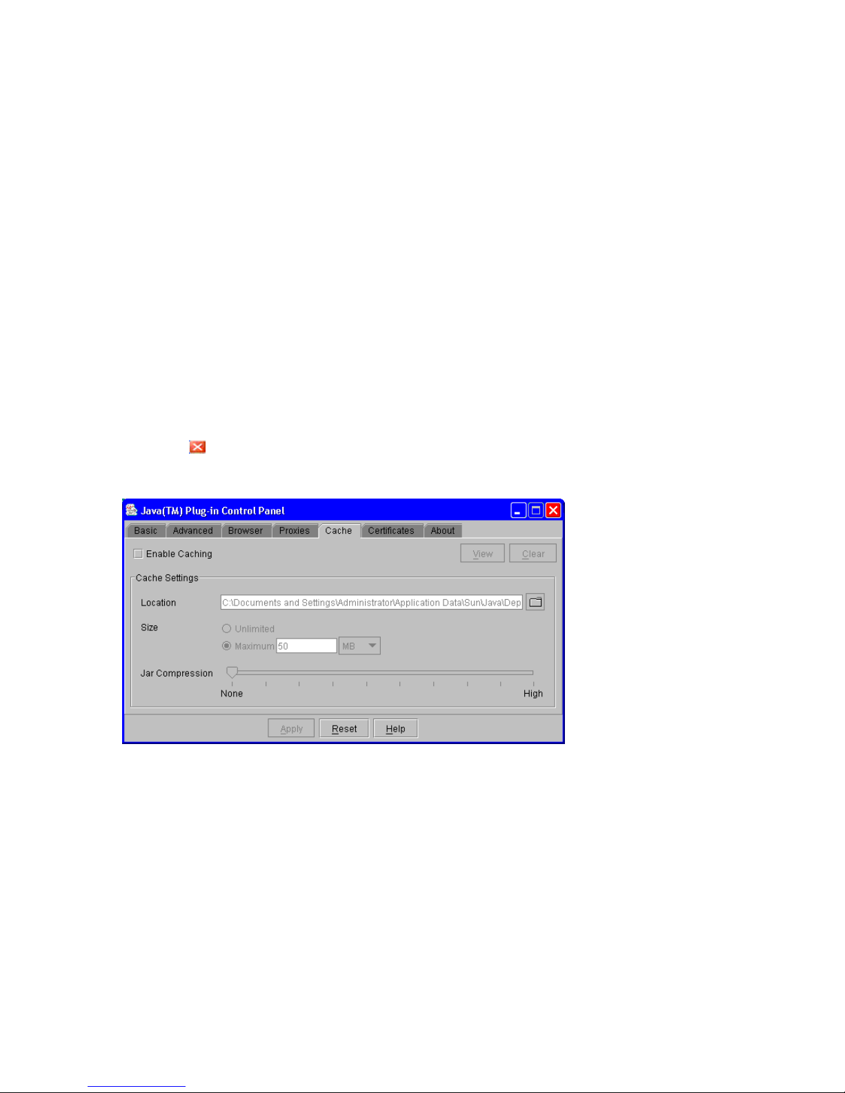
2. Click the Cache tab to display the Cache dialog box.
3. Clear the Enable Caching check box on the Cache dialog box (see Figure 3 (page 24)).
4. If necessary, configure the proxy setting on the Proxies dialog box as the web browser setting.
5. Click Apply.
6. Click to close Java Plug-in Control Panel.
Figure 3 Cache Dialog Box of Java Plug-in Control Panel
JRE 5.0 or JRE 6.0
To enable trace, disable caching, and configure proxy setting for the Java execution:
24 Installation Requirements and Procedures
Page 25

1. Start Java Control Panel.
• For Windows: Go to the Windows Control Panel and double-click the Java icon.
• For UNIX: Do one of the following:
Execute the Java Control Panel executable file. The file is stored in one of the following
locations:
<SDK installation directory>/jre/bin/ControlPanel
<SDK installation directory>/jre/ControlPanel
<JDK installation directory>/jre/ControlPanel
or
Use a web browser to display the Control Panel page. The file is stored in one of the
following locations:
<SDK installation directory>/jre/ControlPanel.html
<JDK installation directory>/ControlPanel.html
2. Click the Advanced tab of Java Control Panel.
3. Double-click Debugging in the tree.
4. Under Debugging, select the Enable tracing check box and the Enable logging check box (see
Figure 4 (page 26)).
5. Click the General tab of Java Control Panel.
6. Click Settings in Temporary Internet Files to display the Temporary Files Settings dialog box.
7. Do the following in the Temporary Files Settings dialog box:
• For JRE 5.0: Select Maximum in Amount of disk space to use and enter 0 (see
Figure 5 (page 26)).
• For JRE 6.0 earlier than Update 10: Clear the Keep temporary files on my computer check
box (see Figure 6 (page 27)).
• For JRE 6.0 Update 10 or later: Select the Keep temporary files on my computer check
box and specify 1 MB for Disk Space (see Figure 7 (page 27)).
8. Click OK to close the Temporary Files Settings dialog box.
9. If necessary, configure the proxy setting on the Network Settings dialog box as the web
browser setting.
To display this dialog box, click the General tab of Java Control Panel and click the Network
Settings button.
10. Click Apply.
11. Click OK to close Java Control Panel.
Setting Up Remote Web Console 25
Page 26
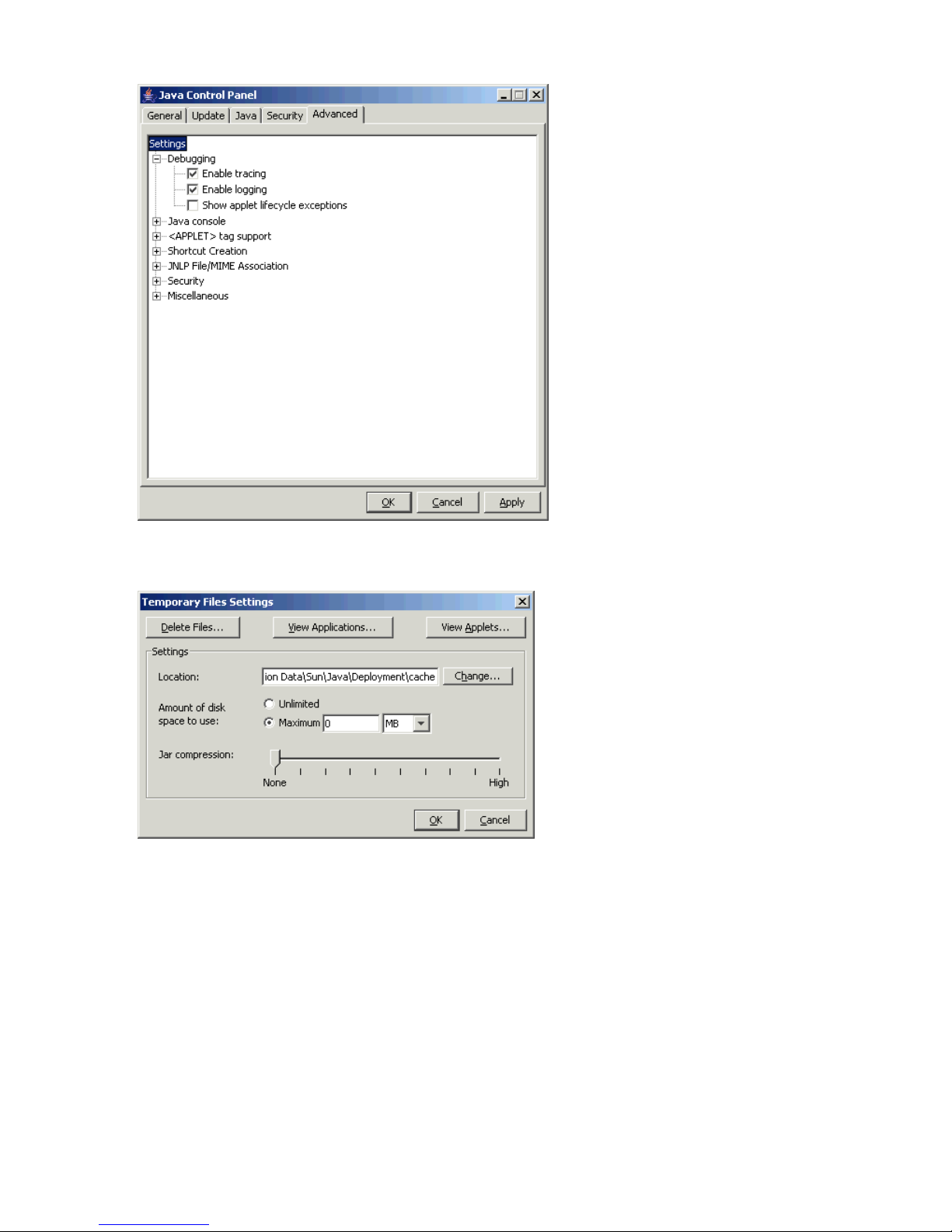
Figure 4 Advanced Dialog Box
Figure 5 Temporary Files Settings Dialog Box (for JRE 5.0)
26 Installation Requirements and Procedures
Page 27
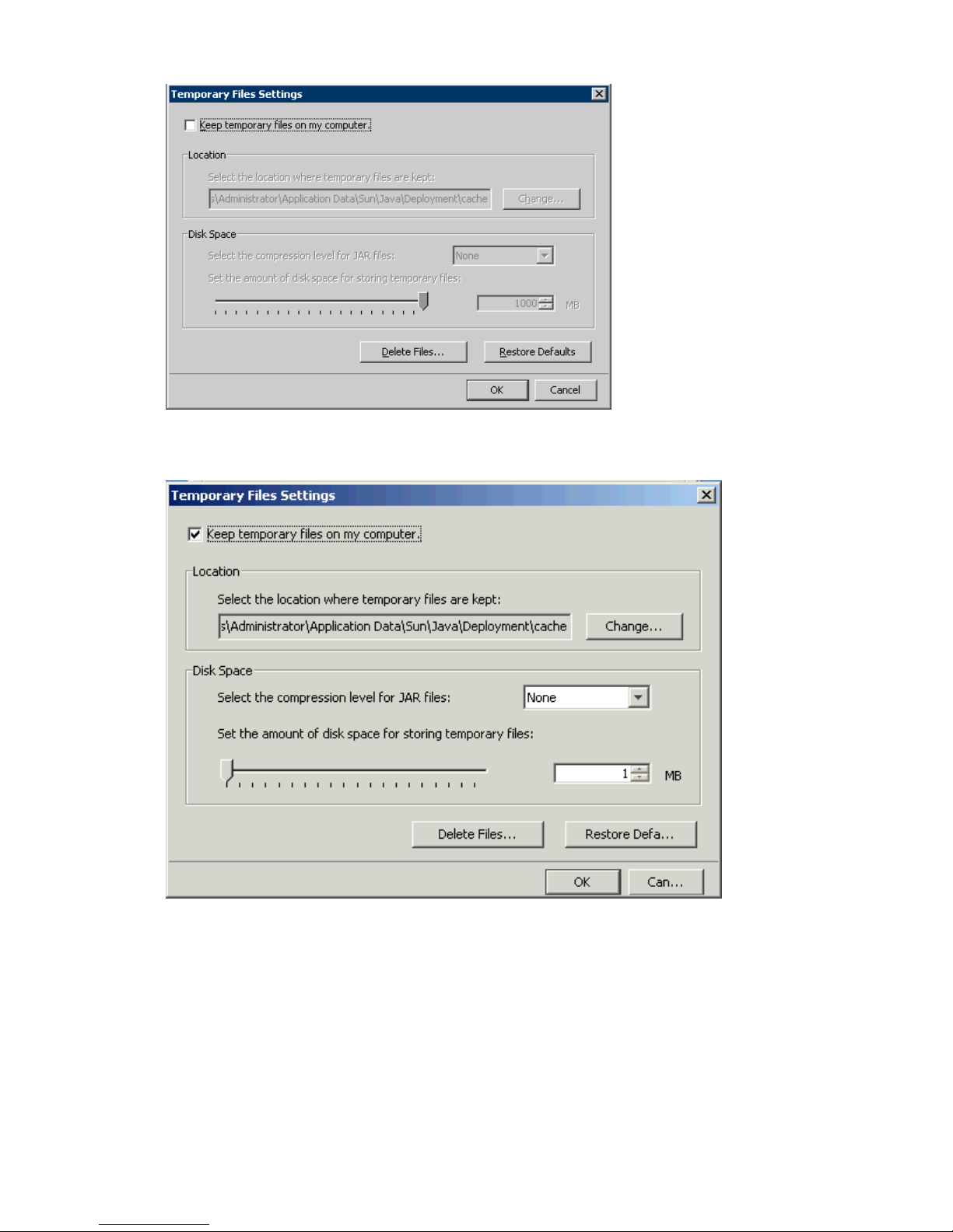
Figure 6 Temporary Files Settings Dialog Box (for JRE 6.0 earlier than Update 10)
Figure 7 Temporary Files Settings Dialog Box (for JRE 6.0 Update 10 or later)
Configuring Communications over only IPv6
IPv6 can also be used for communications between a Remote Web Console computer and an SVP.
To communicate over only IPv6, both a Remote Web Console computer and an SVP must be
configured to use only IPv6 for communications. For information on how to configure an SVP,
contact HP technical support (see “Calling HP Technical Support” (page 138)).
To use both IPv4 and IPv6 for communications, do not apply the setting described in this section.
In this case, IPv4 has a priority over IPv6.
This section explains how to configure a Remote Web Console computer when its operating system
is Windows Vista or Solaris 10. For other operating systems, contact the appropriate developers.
• For Windows Vista
Setting Up Remote Web Console 27
Page 28
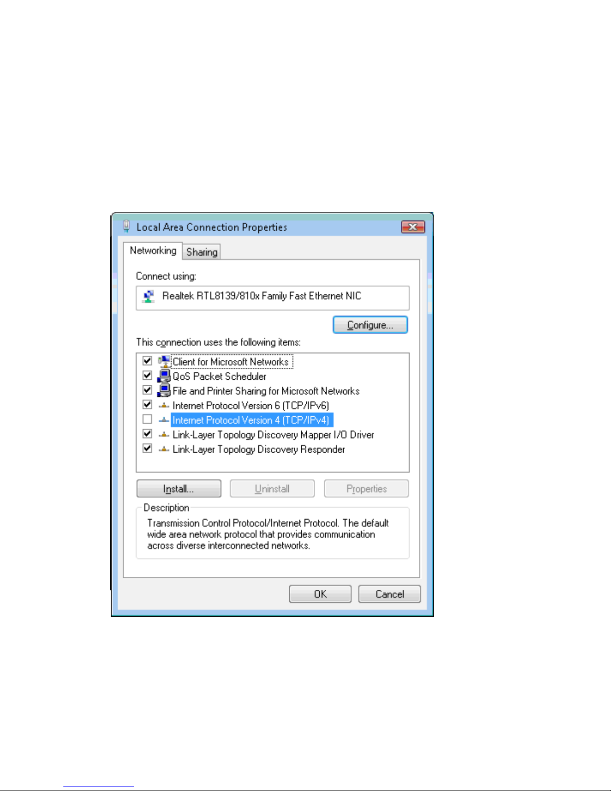
To configure a computer to use only IPv6 for communications:
1. Select the Windows Control Panel, Network and Sharing Center, and then Manage
Network Connections.
2. Select and right-click a network that connects an SVP, and click Properties in the pop-up
menu.
3. Click Continue if the User Account Control dialog box appears.
The Networking dialog box displays properties of the selected network (see Figure 8 (page
28)).
4. Clear the Internet Protocol Version 4 (TCP/IPv4) check box in the list.
5. Click OK to close the dialog box.
Figure 8 Networking Dialog Box for Windows Vista
• For Solaris 10
To configure a computer to use only IPv6 for communications:
1. Start the console.
2. Execute the following command:
ifconfig network-interface-name inet down
28 Installation Requirements and Procedures
Page 29

Remote Web Console Conventions
General Parameters
• In most Remote Web Console windows, if you change a value, the text color of that value
changes to blue or the icon changes, but the changes are not implemented until you click
Apply. Table 11 (page 29) describes the text colors and font types displayed in the Remote
Web Console windows.
Table 11 Text Color and Font Type Displayed on Windows
DescriptionColor and font type
Indicates that you have changed settings on the window, but the changes are not
yet implemented. To implement the changes, click Apply.
Blue bold italic
Used for Performance Monitor and HP StorageWorks XP Performance Control
Software.
For more information, see the HP StorageWorks XP24000/XP20000 Performance
Monitor User Guide and HP StorageWorks XP24000/XP20000 Performance Control
User Guide.
Red italic
Used for the copy function of LUN Manager. For more information, see the HP
StorageWorks XP24000/XP20000 LUN Manager User Guide.
Green bold
• You can create and store up to 20,000 settings or operations before actually applying them
to the storage system. To avoid a possible error, do not apply more than 20,000 settings at
a time.
• The layout of a Remote Web Console window is reset when you click Apply, Cancel, Refresh
( ), or Refresh All ( ) on the File menu, or when you switch tabs.
• When you click Refresh All ( ) on the File menu, the information on the SVP is also updated.
Therefore, the processing caused by Refresh All ( ) on the File menu can take some time.
• If there is a difference between the configuration information displayed on the Remote Web
Console and the actual configuration information that can be recognized from the host, the
configuration information displayed on the Remote Web Console can be updated by clicking
Refresh All ( ) on the File menu.
• Do not change the clock time of the Remote Web Console computer while you are using
Remote Web Console.
Log in to Remote Web Console again after you have changed the clock time of the Remote
Web Console computer.
• When the microcode is being updated on the SVP, you must exit and restart all web browsers
on the Remote Web Console.
• If a Remote Web Console user is applying settings, you cannot log in to Remote Web Console
until after those settings have been applied. A wait of longer than five minutes indicates an
abnormal end, in which case you need to exit and restart the browser.
• When an internal process is being executed on the SVP (for example, a configuration change,
option selection, or operational information query), Remote Web Console processing might
be temporarily delayed.
Remote Web Console Conventions 29
Page 30

• If you request a change to the storage system configuration while another change is being
made, an error message is displayed.
◦ If the error occurs while you are logging in or clicking Apply to implement changes, wait
for a few minutes, and then retry the operation.
◦ If the error occurs while you are either switching between Modify mode and View mode
or switching tabs, wait for a few minutes, click Refresh ( ) on the File menu, and then
retry the operation.
• If you remain in Modify mode for a certain period of time without making any changes (the
default is 30 minutes), the storage system releases the Modify mode, and you are returned to
View mode. You can change the timeout period. After the Modify mode is released, an error
occurs if you attempt the following actions: clicking Apply, Refresh ( ), or Refresh All ( )
on the File menu, or mode changing buttons ( or ). You can only see information on
Remote Web Console.
• When the HP StorageWorks XP Business Copy Software or Hitachi ShadowImage™ for
Mainframe quick restore operation is being performed, a Remote Web Console window may
display old information (status before the quick restore operation) on logical volume (LDEV)
configurations. In this case, wait until the quick restore operation completes, and then click
Refresh ( ) or Refresh All ( ) on the File menu to update the Remote Web Console window.
• Do not adjust your computer display while using Remote Web Console (for example, change
the screen resolution or logging in by using the Remote Desktop feature of Microsoft). If you
do so and see unexpected results, return to the normal display by restarting Remote Web
Console.
Certain screen savers change the screen resolution automatically, so you should not use them
while using Remote Web Console.
• Make sure that the Remote Web Console computer does not enter standby or hibernate mode
while using Remote Web Console.
For example, do not manually switch to standby or hibernate mode. Also, do not configure
the Remote Web Console computer to automatically enter standby or hibernate mode if no
operation is performed for a certain period of time. If the Remote Web Console computer
enters standby or hibernate mode, and then returns to normal mode, restart Remote Web
Console.
• If software that has an auto login function is installed on the Remote Web Console computer,
disable the auto login function. The auto login function automatically submits a user ID and
password by using the autocomplete function of a web browser. This allows users to
automatically log in to a program.
Keystrokes and Navigation
• Table 11 (page 29) lists and describes the text colors and font types displayed on the Remote
Web Console windows.
• In general, you can select an object in a window by clicking the mouse. Certain commands
can be displayed by right-clicking an object. In some cases, you can use the mouse button to
drag and drop an item. This is noted in the instructions for each operation. You can sort objects
listed in a table by selecting the header of a column you want to sort.
• You cannot use the mouse wheel feature.
• You cannot use the Home, End, or Delete keys for Remote Web Console operations.
• Do not hold down the arrow keys or the Enter key for a while when a tree or list is selected.
Instead, press these keys multiple times.
30 Installation Requirements and Procedures
Page 31

• As a general rule, you can only enter alphanumeric characters (ASCII codes) into a text box.
There are certain exceptions, including the following:
” \ ; : * ? < > | / # & + = ,
Which symbols are usable depends on the window and the program product options. For
further information, see the corresponding sections or documents.
• After dragging and dropping objects to another location or area, you might not be able to
use the scroll bar in that location or area. If this occurs, close all windows, and then log in
again.
• You cannot drop an object to an area or location where no object exists. When you attempt
to drop an object in an invalid area or location, no warning icon is displayed.
• To drag and drop adjacent objects, use the Shift key to select the objects. Hold down the Shift
key while you select the last object in the group. Drag and drop the objects.
• To drag and drop nonadjacent objects, use the Ctrl key to select the objects. Continue to hold
the Ctrl key down while you drag and drop the objects.
• When you try to drag and drop multiple objects, the items may remain selected. If this happens,
repeat the drop operation.
• On rare occasions, the shape of the icon (object) does not change after the drag and drop
operation, but this is not a problem.
See “Troubleshooting” (page 132) for troubleshooting errors and actions during operations on the
Remote Web Console computer.
UNIX
When you use the Remote Web Console on UNIX workstations, the following additional parameters
apply:
• Remote Web Console windows:
You cannot change the window size.◦
◦ The styles and colors of some windows are displayed differently from those windows
displayed on Windows systems.
• Mozilla browser:
If a java_vm process or a Mozilla browser process hangs, Remote Web Console
performance becomes abnormal. Delete the abnormal process and continue with Remote
Web Console operations.
◦
◦ When you use the Remote Web Console on the Japanese version of the Mozilla browser,
enter the following commands using the X Server Emulator:
B Shell:
LANG=C
export LANG
C Shell:
setenv LANG C
• After installing the JRE file on UNIX workstations, enter the following commands using the
shell:
B Shell:
PATH=$PATH:[JRE installation directory path]/jre/bin
export PATH
C Shell:
setenv PATH ${PATH}:[JRE installation directory path]/jre/bin
Remote Web Console Conventions 31
Page 32

• HP StorageWorks XP Auto LUN Software and XP Performance Control windows:
You cannot drag and drop objects on the XP Auto LUN and XP Performance Control
windows. You must use the buttons instead.
◦
◦ If you select the icon for the Remote Web Console main window when you are using
either XP Auto LUN or XP Performance Control, these windows may be wholly or partially
obscured behind the Remote Web Console main window. Before you can use the Remote
Web Console main window, close these windows by clicking the button. This terminates
the process. To continue the process, select the XP Auto LUN or XP Performance Control
window to bring it to the foreground.
◦ The Close button ( ) on the XP Auto LUN or XP Performance Control window remains
active even if you click Apply and the processing is being executed. If you click the
button after clicking Apply, the window closes but processing continues.
◦ For the first two operations only, the word Loading... is displayed on the message box
of the XP Auto LUN and the XP Performance Control window. This message does not
appear for the third and later operations.
• When you use the Remote Web Console on UNIX workstations:
You cannot drag and drop objects on the LUN Manager window. You must use the buttons
instead.
• When you use the Remote Web Console on HP-UX workstations:
If you select any part of the Remote Web Console main window while a dialog box is
displayed, that dialog box may be wholly or partially obscured behind the Remote Web
Console main window. Before you can use the Remote Web Console main window, close
the obscured dialog box first.
Windows Server 2003/2008 Initial Setup
If you are using a Windows Server 2003/2008 computer, the following operations are necessary.
When you use the Remote Web Console for the first time, perform the following operation in
Internet Explorer before using the Remote Web Console.
1. Select Tools and then Internet Options from the menu bar of Internet Explorer.
The Internet Options dialog box appears.
2. Click the Advanced tab. The Advanced dialog box appears (see Figure 9 (page 33)).
3. Clear the Do not save encrypted pages to disk check box.
4. Click OK to close the Advanced dialog box.
32 Installation Requirements and Procedures
Page 33
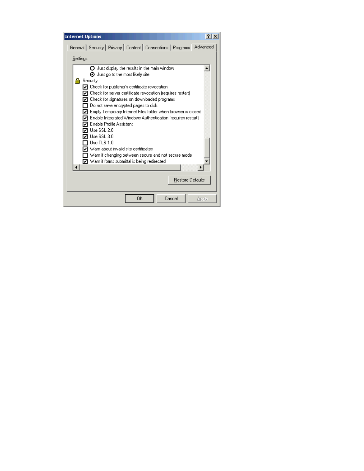
Figure 9 Advanced Dialog Box (Internet Options, Internet Explorer)
If a page is not displayed because of an Invalid syntax error, you must register the URL of the
desired SVP to the trusted site with the following procedure:
1. Select Tools and then Internet Options from the menu bar of Internet Explorer.
The Internet Options dialog box appears.
2. Click the Security tab.
The Security dialog box appears (see Figure 10 (page 34)).
3. Click Trusted sites.
4. Click Sites.
The Trusted sites dialog box appears (see Figure 11 (page 34)).
5. Input the URL of the desired SVP to the Add this Website to the zone box.
6. Click Add.
7. Click Close to close the Trusted sites dialog box.
8. Click OK to close the Security dialog box.
Remote Web Console Conventions 33
Page 34
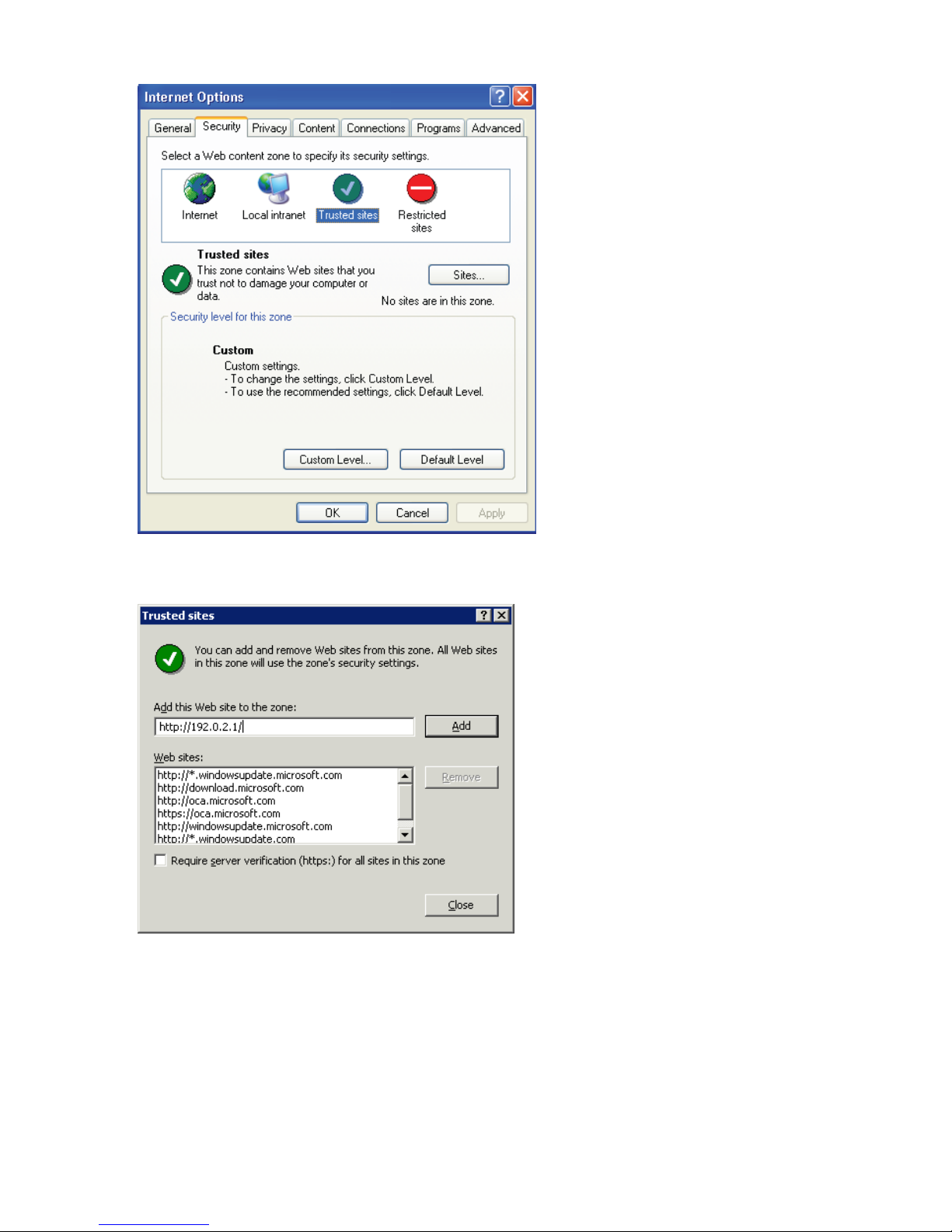
Figure 10 Security Dialog Box (Internet Options, Internet Explorer)
Figure 11 Trusted sites Dialog Box (Internet Explorer)
Starting Up and Logging In to Remote Web Console
This section provides an overview of the login procedure and how to log in to a storage system.
34 Installation Requirements and Procedures
Page 35
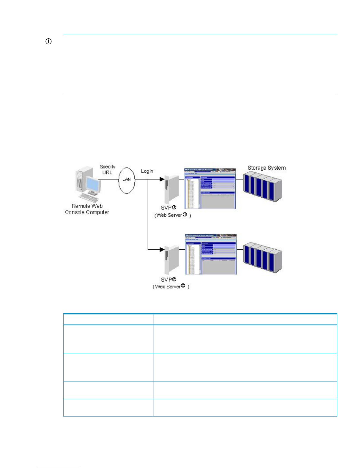
Overview of Login Procedures
IMPORTANT: Because the initial user ID administrator has administrator privileges, one of the
first tasks for the Remote Web Console administrator should be to change the password to maintain
protection of the administrator-only and restricted functions. If you are logging in to Remote Web
Console for the first time, use the initial user ID (administrator) and password (administrator) to log
in as a storage administrator, and then change the password. All user IDs and passwords are
case-sensitive. If the administrator password is lost or forgotten, you must call HP technical support
to regain access to the restricted functions.
All Remote Web Console (Java client) users are required to log in to the Remote Web Console
SVP (web server) with a valid user ID and password before executing the Remote Web Console
Java application program. You need the user account for which the Account Administrator Role is
set to Modify to register the Remote Web Console user accounts (see “Account Window” (page 70)).
Figure 12 (page 35) shows an overview of the login process.
Figure 12 Login Process
Table 12 Specifications and Restrictions Concerning Login Operations
SpecificationItem
The storage system can support up to 32 concurrent users.
The exceptions are displaying the Performance Monitor window and executing
the Export Tool, where the limit is two concurrent users.
Maximum number of concurrent users
The same user can concurrently log in to more than one SVP.
If you execute multiple Java application programs for multiple SVPs, insufficient
memory may degrade performance.
Logging in to multiple SVPs (web
servers)
The same user (ID) may not have multiple concurrent sessions with the same
SVPs (web servers).
Logging in to the same SVPs (web
servers) more than once concurrently
If you have failed to log in three times with the same user ID, Remote Web
Console stops replying for one minute. However, it is not a system failure.
Security measure
Starting Up and Logging In to Remote Web Console 35
Page 36
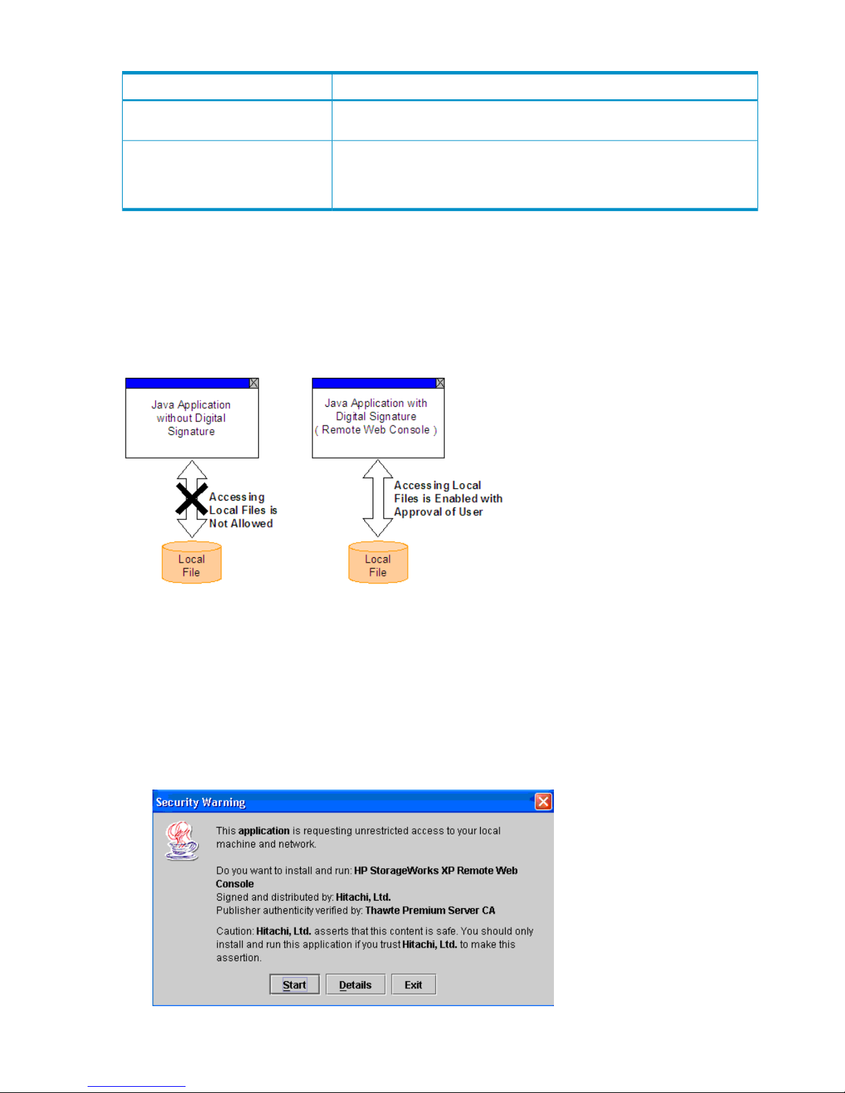
Table 12 Specifications and Restrictions Concerning Login Operations (continued)
SpecificationItem
All login information, including user ID, login and logoff time, is recorded in
the audit log file so that unauthorized access can be detected.
Login history
If a user cannot log out normally, you can set the user to be automatically
logged out from the SVP after a specific period of time. This period of time can
be specified by the storage administrator with the Storage Administrator Role
set to Enable.
Automatic logout operation
Permission for Accessing Local Client Files
Java applications have a security feature that prohibits the Java applications from accessing local
files on client computers. To use Remote Web Console, you must give Remote Web Console
permission to access local files on your computer.
Figure 13 (page 36) shows the concept of the Java application security.
Figure 13 Concept of Java Application Security
Figure 13 (page 36) shows that Remote Web Console with digital signature can access local files
with user approval. The digital signature has an expiration date that might be expired depending
on the Remote Web Console version you use. Even if the digital signature is expired, you can
continue using Remote Web Console.
The dialog box that appears when you log in depends on the JRE versions. See the following
description and take the appropriate action in the displayed dialog box.
• For JRE 1.4
Figure 14 Security Warning Dialog Box (for JRE 1.4)
36 Installation Requirements and Procedures
Page 37
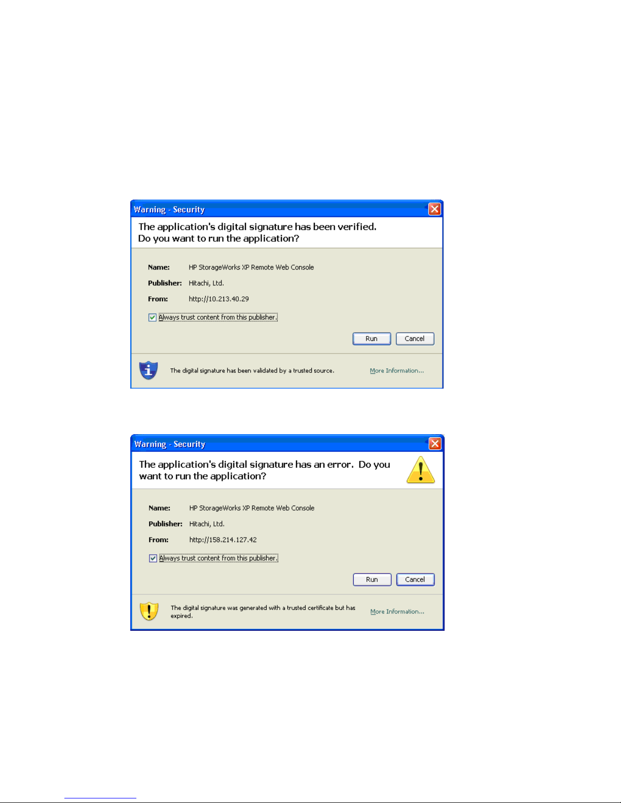
The items on this dialog box are as follows:
◦ Start allows you to log in to Remote Web Console (regardless of whether the digital
signature is expired).
◦ Details allows you to view detailed information about the Java application.
◦ Exit prohibits you from using Remote Web Console.
• For JRE 5.0 or JRE 6.0
One of the following dialog boxes will be displayed depending on your operational
environment.
Figure 15 Warning - Security Dialog Box (for JRE 5.0)
Figure 16 Warning - Security Dialog Box When Digital Signature Is Expired (for JRE 5.0)
The items on these dialog boxes are as follows:
◦ Always trust content from this publisher
Selecting the Always trust content from this publisher check box means that you approve
Remote Web Console as a secure Java application and that local file access is ensured
from now on (regardless of whether the digital signature is expired).
Starting Up and Logging In to Remote Web Console 37
Page 38

If you select the Always trust content from this publisher check box and click Run, Remote
Web Console is always allowed to access the local files and you will not see this dialog
box again.
◦ Run allows you to log in to Remote Web Console (regardless of whether the digital
signature is expired).
◦ Cancel prohibits you from using Remote Web Console.
Logging In to a Storage System
To log in to a storage system:
1. Start the Remote Web Console computer, and start your web browser.
2. Enter the IP address or fully qualified DNS name of the SVP in the web browser. The Login
dialog box appears (see Figure 17 (page 39)).
• If a dialog box appears and asks if you want to run the application, follow the instruction
in “Permission for Accessing Local Client Files” (page 36).
• If the SVP is set to support SSL-encrypted communication, security messages might appear.
For details, see “Using SSL-Encrypted Communication” (page 39).
• If you are using a Windows Server 2003/2008 computer, a message as shown in
Figure 23 (page 41) may appear. If this message appears, take the steps described in
“Using Windows Server 2003/2008” (page 41).
• If you are using Windows and JRE is not installed on the Remote Web Console computer,
JRE is automatically installed via the Internet when you log in to Remote Web Console.
However, an error such as shown by Figure 18 (page 39) can occur because of the
condition of the download server. If an error occurs, download JRE from the Java website
(see “Configuring the Web Browser” (page 22)).
3. Enter the user ID and password.
If you have failed to log in three times with the same user ID, Remote Web Console stops
replying for one minute. However, it is not a system failure.
4. Click Login to log in to the SVP.
The Remote Web Console main window opens (see “Remote Web Console Main Window”
(page 51)).
If the SVP is set to support SSL-encrypted communication, the Security Information dialog box
may appear (depending on the web browser you use). If it appears, click Yes to open the
Remote Web Console main window.
38 Installation Requirements and Procedures
Page 39
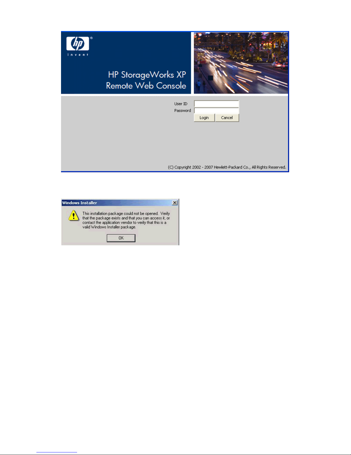
Figure 17 Login Dialog Box
Figure 18 Error Message on JRE Installation
Using SSL-Encrypted Communication
If the SVP is set to support SSL-encrypted communication, the Security Alert dialog box (see
Figure 19 (page 40)) is displayed when you log in to Remote Web Console. Click OK on the
Security Alert dialog box.
Furthermore, the Security Alert dialog boxes for the certificate may also be displayed.
• If Figure 20 (page 40) is displayed, click View Certificate to confirm that the certificate is
correct, and click Yes.
• If Figure 21 (page 40) is displayed, view more information to confirm that the certificate is
correct, and click Yes. If you select the Always trust content from this publisher check box and
click Yes, you will not see this dialog box again.
• If Figure 22 (page 41) is displayed, click Run.
Starting Up and Logging In to Remote Web Console 39
Page 40
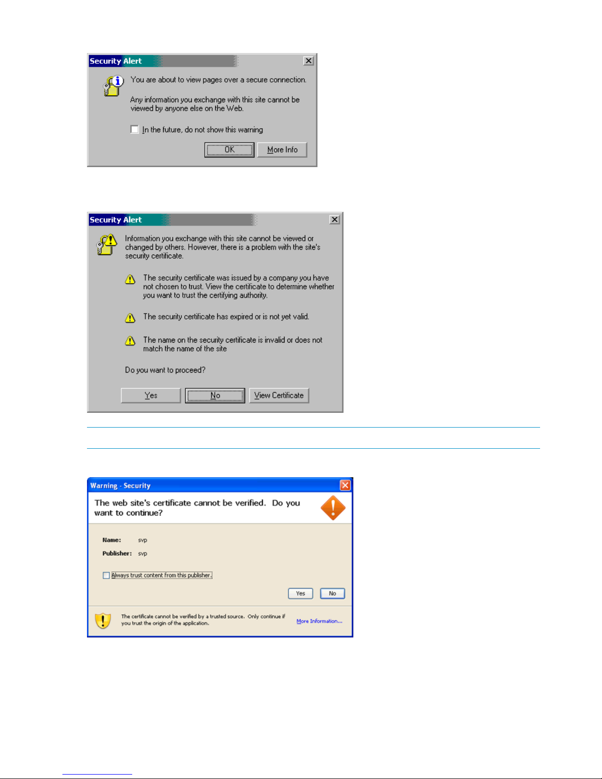
Figure 19 Security Alert Dialog Box
Figure 20 Security Alert Dialog Box for the Certificate
NOTE: Displayed statements and icons may be different.
Figure 21 Warning - Security Dialog Box for the Certificate
40 Installation Requirements and Procedures
Page 41
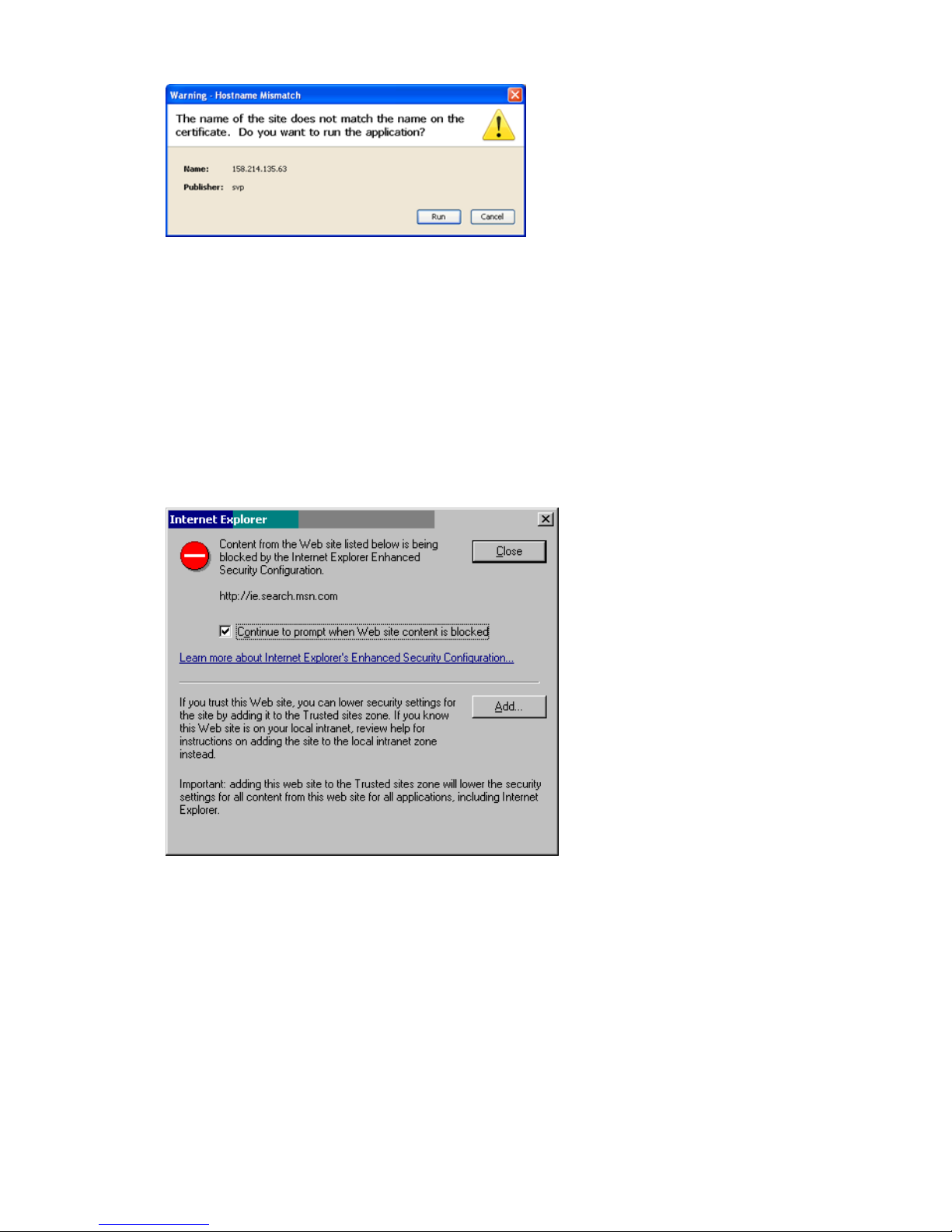
Figure 22 Warning - Hostname Mismatch Dialog Box
Using Windows Server 2003/2008
If you are using a Windows Server 2003/2008 computer, a message as shown in Figure 23 (page
41) may appear during the login operation. If this message appears, take the following steps:
1. Click Add in the message box. The Trusted sites dialog box appears (see “Trusted sites Dialog
Box (Internet Explorer)” (page 34)).
2. In Add this Website to the zone, enter the IP address of the SVP that you want to log in.
3. Click Add. The URL of the SVP is added to the Websites list.
4. Click Close. The Trusted sites dialog box closes.
Figure 23 Internet Explorer Message (When Logging In to the SVP from a Windows Server
2003/2008 Computer)
Changing Between View Mode and Modify Mode
Remote Web Console has two operation modes: Modify and View.
• View mode is for viewing the settings of the storage system. The operation mode is View mode
when you log in to Remote Web Console.
• Modify mode locks the setting operation of other users so that they cannot change the settings
of the storage system.
You must operate in Modify mode to change the settings of the storage system. You also need
the operation privileges of the function to change the settings of the storage system. For detailed
information on setting operation privileges, see “Changing User Operation Privileges”
(page 103).
Only one user can be in Modify mode for each storage system. While a storage administrator is
in Modify mode, all other users can only view the storage system information in View mode. If the
Starting Up and Logging In to Remote Web Console 41
Page 42
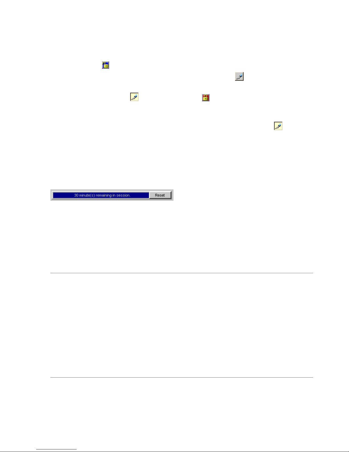
storage system is partitioned, only one user can be in Modify mode for each SLPR. Any other users
in the allocated SLPR can only view the storage system information in View mode. Some dialog
boxes are not displayed in View mode. To view such information in View mode, view the Reports
Display dialog box.
To change between View mode and Modify mode:
1. Verify that the icon is displayed, which indicates that the storage system is unlocked.
2. Click the Mode Changing icon, which should be in View mode ( ).
Once you are in Modify mode, the Mode Changing icon changes from a gray background
to a yellow background ( ), and the Locked icon ( ) is displayed. Also a progress bar
appears on the Remote Web console main window showing the remaining time period for
Modify mode (see “Extending the Modify Mode Timeout Period” (page 42)).
3. Once you have applied your desired changes, click the Mode Changing icon ( ) to change
back to View mode.
Extending the Modify Mode Timeout Period
When you change from View mode to Modify mode, a progress bar showing the Modify mode
timeout period appears on the Remote Web Console main window.
Figure 24 Progress Bar Showing the Modify Mode Timeout
The progress bar shows the remaining time period in which Modify mode is available. The remaining
time period for Modify mode is also numerically displayed on the progress bar. The default for
the Modify mode timeout period is 30 minutes. You can click the Reset button on the right of the
progress bar to extend the Modify mode time period. For example, if the Modify mode timeout
period is set as 30 minutes (default), the Modify mode time period is extended for 30 minutes, as
you click the Reset button.
If you do not access the SVP while in Modify mode, the progress bar decreases. When you reach
the specified Modify mode timeout period, Modify mode is released.
NOTE: If Modify mode is released due to a time out, the settings made but not yet applied will
be canceled on some windows. Therefore, make sure that you have enough time remaining in
Modify mode to complete your work by clicking Reset while you are using the following windows:
• V-VOL window
• All windows and dialog boxes used for HP StorageWorks XP Continuous Access Software,
HP StorageWorks XP Continuous Access Journal Software, and XP Business Copy operations
• All windows and dialog boxes used for Hitachi TrueCopy™ for Mainframe, Universal Replicator
for Mainframe, and ShadowImage for Mainframe operations
• Volume Security window
• All windows and dialog boxes used for XP External Storage operations
• License Key window
You can change the Modify mode timeout period using the RMI time-out period for Modify parameter
on the Set Env. dialog box. You have to log in as a storage administrator with the Storage
Administrator Role set to Enable to change the setting of RMI time-out period for Modify. See
“Setting the Environment Parameters” (page 106) for instructions. If you disable this parameter by
specifying NO, the progress bar that shows the Modify mode timeout period is not displayed on
the Remote Web Console main window, even though the mode is changed to Modify.
42 Installation Requirements and Procedures
Page 43
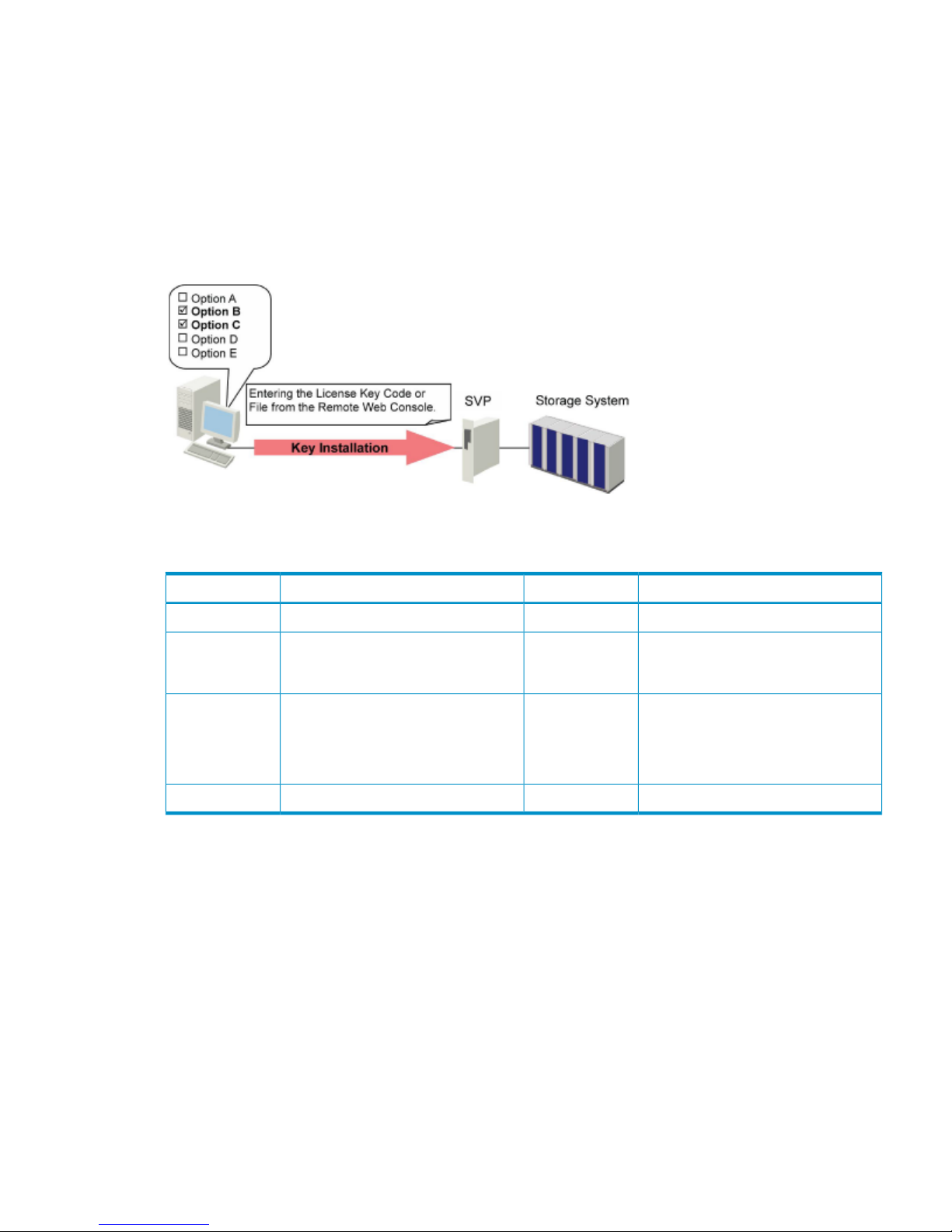
License Keys
A license key is a textual key that functions as a password because it is entered into Remote Web
Console and unlocks the protection of an option. Because each license key is generated with a
storage system serial number and option ID input, each storage system requires a unique license
key code. License key codes for each option (including the Java application) and storage system
are provided when you purchase program product options.
To input the license key, enter a license key code or a license key file containing multiple license
key codes. A license key file is provided when you purchase program product options.
Figure 25 Overview of License Keys and Option Installation
Table 13 (page 43) describes the types of license keys.
Table 13 License Key
Usable CapacityExpirationDescriptionType
No upper limit120 daysLicense key for trial use (Try & Buy).Temporary
Each program product option has an
upper limit of the volume capacity that
can be used.
No limitLicense key for purchase.Permanent
Each program product option has an
upper limit of the volume capacity that
can be used.
365 daysLicense key for purchase.
Days are deducted from 365 days
when the program product option is
activated with the Term key.
Term
No upper limit30 daysLicense key for emergency use.Emergency
Temporary Key
A temporary key is for trial use. 75 days after the temporary license key is installed (or when there
are 45 days left before the expiration), a warning message is displayed on the Remote Web
Console main window when you start the Remote Web Console option. 120 days after the
temporary license key is installed, the temporary license key expires. A message appears warning
the user of the expiration of the license key, and the license key expiration is also reported to the
host. After the temporary key has expired, you cannot re-install the temporary key for 180 days.
• When the license key for a program product expires, the license key for a program product
that requires the expired program product will be also disabled.
• For ShadowImage for Mainframe, XP Business Copy, TrueCopy for Mainframe, XP Continuous
Access, Universal Replicator for Mainframe, XP Continuous Access Journal, HP StorageWorks
XP External Storage Access Manager Software, LUN Manager, XP Auto LUN, Volume Security,
License Keys 43
Page 44

Volume Retention Manager, and Data Retention Utility, the expiration of a temporary license
key has the following effects:
◦ No new configuration settings may be performed.
◦ The configuration settings that were made before the temporary license key expired
remain in effect and cannot be deleted. Non-configuration settings that were made before
the temporary license key expired can be deleted from the SVP only (not from Remote
Web Console).
• For Virtual LVI/LUN, LUN Expansion, Cache Residency Manager for Mainframe, Cache
Residency Manager, HP StorageWorks XP for Compatible Parallel Access Volumes Software,
and HP StorageWorks XP Compatible Hyper PAV, the expiration of a temporary license key
has the following effects:
◦ No new configuration settings may be performed.
◦ The configuration settings that were made before the temporary license key expired
remain in effect and cannot be deleted.
• For Performance Monitor and XP Performance Control, the expiration of a temporary license
key has the following effects:
◦ No monitoring functions may be performed.
◦ No new configuration settings (for example, upper limit control, threshold control, or
selection of port type) may be performed.
◦ Configuration settings that were made before the temporary license key expired may be
expunged from the SVP only (not from the Remote Web Console). Contact your HP service
representative (see “Calling HP Technical Support” (page 138)).
Permanent Key
A permanent key is purchased to use program product options indefinitely. A permanent key has
an upper limit of volume capacity that can be used for each program product option.
Before purchasing the permanent key, you need to estimate the volume capacity that can be used
for the program product option. This volume capacity is called the licensed capacity. If you add
volumes and the available amount of volume capacity exceeds the licensed capacity, Capacity
Insufficient is displayed in Status in the License Key window. In this case, you need to purchase
the additional license to cover the capacity shortage within 30 days. For details on the licensed
capacity, see “Licensed Capacity” (page 45).
If you use HP StorageWorks XP Thin Provisioning Software, the licensed capacity might become
insufficient even though you did not add any volumes. When you use XP Thin Provisioning, see
the HP StorageWorks XP24000/XP20000 Thin Provisioning Software User Guide for details on
the license capacity.
Term Key
A term key is purchased to use the program product option for a specified number days.
• The term key is available for 365 days.
• You can set the term key to enable or disable each program product option.
Only days when the program product option is enabled with the term key are deducted from
the 365 days when the date changes.
For example, if the term key is set to Enable for 150 days and set to Disable for 100 days
after you installed the term key, there are 215 remaining days (365 days minus 150 days),
although 250 days have passed in total.
You can delay the expiration of the term key by setting the term key to Disable when you are
not using the program product option.
44 Installation Requirements and Procedures
Page 45

• The term key, which is the same as the permanent key, has a limit for the volume capacity
that can be used for each program product option.
If you add volumes and the available amount of volume capacity exceeds the licensed capacity,
Capacity Insufficient will be displayed in Status in the License Key window. In this case, you
need to purchase an additional license to cover the capacity shortage within 30 days. For
details on the licensed capacity, see “Licensed Capacity” (page 45).
If you use XP Thin Provisioning, the licensed capacity might be insufficient even if you did not
add any volumes. When you use XP Thin Provisioning, see the HP StorageWorks
XP24000/XP20000 XP Thin Provisioning Software User Guide for details on the license
capacity.
• If the term key has expired, you can install a program product option with another license
key.
When the term key has expired, Not Installed is displayed in Status in the License Key window.
You can install the temporary key, the term key, the emergency key, or the permanent key to
the program product option in this status.
• When the license key for a program product (A) expires, the license key for a program product
(B) that requires the expired program product (A) will be also disabled.
When this occurs, Not Enough is displayed in the Status of the program product (B) in the
License Key window.
Emergency Key
An emergency license key is used in situations where the temporary key or the term key is set to
expire in the near future and the user cannot get the permanent key in time because of special
circumstances (for example, a licensed server has crashed or there are problems with the
communication infrastructure). An emergency key may also be used when a user who does not
intend to purchase the option needs to undo a configuration change that was made during the
lifetime of the temporary key or the term key.
• An emergency key is effective for 30 days.
If you forcibly install an emergency key for an option that already has a permanent key or
term key, the license for that option will expire in 30 days.
• When the license key for a program product expires, the license key of a program product
that requires the expired program product will be also disabled.
Licensed Capacity
The licensed capacity is the volume capacity that you are licensed to use with a program product
option. You need to estimate the amount of capacity that you want to use with the program product
option before you purchase the permanent key or the term key. The licensed capacity has three
types depending on the program product option.
Table 14 (page 46) explains the licensed capacity types and how to estimate the licensed capacity.
For details on which licensed capacity type should be estimated for the program product option,
see “Remote Web Console Options and Licensed Capacity” (page 47).
Licensed Capacity 45
Page 46

Table 14 Licensed Capacity Type
How to Estimate the Licensed CapacityExplanationType
See “Estimating Licensed Capacity
Based on Used Capacity” (page 46).
The licensed capacity is estimated using the
capacity that the program product option will use.
The estimated capacity differs depending on the
program product option:
• Normal volumes (local volumes)
• External volumes mapped to the storage system
• Pools
Used capacity
See “Estimating Licensed Capacity
Based on Mounted Capacity”
(page 47).
The licensed capacity is estimated using the
capacity mounted in the entire disk drive of the
storage system.
Mounted capacity
N/AYou can use the program product option, regardless
of the volume capacity.
Unlimited capacity
Estimating Licensed Capacity Based on Used Capacity
There are three capacities to use for estimating the licensed capacity, depending on the program
product option:
• Normal volume capacity
The method to calculate normal volume capacity depends on the volume emulation types.
Table 15 Methods for Calculating Capacity of a Normal Volume
Formula for Calculating Capacity of a Normal VolumeVolume Emulation Type
720 KB x (number of user cylinders)3380-x
870 KB x (number of user cylinders)3390-x
Same as the capacity specified when creating the volume.OPEN-x
NOTE: In the left column of Table 15 (page 46), x indicates a number or a letter. For example,
OPEN-x refers to emulation types such as OPEN-3 and OPEN-V.
You can use the formulas in Table 15 (page 46) to estimate capacity for purchase. An example
is given in Table 16 (page 46).
Table 16 An Example of Estimating Capacity for Purchase Based on Used Capacity
ValueItem
3390-3Volume emulation type
3,339Number of user cylinders
2,048Number of volumes
870 KB x 3,339 x 2,048 = 5,949,296,640 KB
5,949,296,640 KB 1,024 = 5,809,860 MB
5,809,860 MB 1,024 = 5,673.70 GB
5,673.70 GB 1,024 = 5.54 TB
Total capacity of all the volumes
At least 6 TBEstimated capacity for purchase
• External volume capacity
The method to calculate external volume capacity is as follows:
46 Installation Requirements and Procedures
Page 47

External Volume Capacity (KB) = Volume Capacity (number of blocks) × 512 (byte) 1,024
• Pool capacity
The license capacity of XP Thin Provisioning is calculated using the total capacity of the
XP Thin Provisioning pool.
◦
◦ If you use V-VOLs of XP Thin Provisioning as P-VOLs or S-VOLs of XP Business Copy/XP
Continuous Access/XP Continuous Access Journal, the license capacity of XP Business
Copy/XP Continuous Access/XP Continuous Access Journal is calculated using the page
capacity allocated to the XP Thin Provisioning V-VOLs (that is, used pool capacity).
For instructions on how to calculate pool capacity, see the HP StorageWorks
XP24000/XP20000 Thin Provisioning Software User Guide.
Estimating Licensed Capacity Based on Mounted Capacity
To estimate licensed capacity based on mounted capacity, convert both capacities to the GB unit.
When converting mounted capacity from TB to GB units, multiply by 1,000. On the other hand,
when converting licensed capacity from TB to GB units, multiply by 1,024.
Table 17 Example A of Estimating Capacity for Purchase
ValueItem
10.3 TB = 10.3 x 1,000 = 10,300 GBMounted capacity
10 TB = 10 x 1,024 = 10,240 GB < 10,300 GB
11 TB = 11 x 1,024 = 11,264 GB > 10,300 GB
Licensed capacity
At least 11 TBEstimated capacity for purchase
As shown in Table 18 (page 47), the required licensed capacity is not always greater than the
mounted capacity. At larger capacities, the difference between the conversion factors (1,000 and
1,024) has a greater (inverse) effect on the equivalent licensed capacity.
Table 18 Example B of Estimating Capacity for Purchase
ValueItem
165.62 TB = 165.62 x 1,000 = 165,620 GBMounted capacity
161 TB = 161 x 1,024 = 164,864 GB < 165,620 GB
162 TB = 162 x 1,024 = 165,888 GB > 165,620 GB
Licensed capacity
At least 162 TBEstimated capacity for purchase
Remote Web Console Options and Licensed Capacity
Table 19 (page 47) lists the options for the Remote Web Console and the licensed capacity type.
Only some of the Remote Web Console options are available to storage partition administrators.
For the available options for storage partition administrators, see the HP StorageWorks
XP24000/XP20000 Disk/Cache Partition User Guide.
Table 19 Remote Web Console Options
NotesLicensed CapacityOption Name
Java application programs that are
downloaded from the SVP to Remote
Web Console.
Mounted CapacityRemote Web Console (includes the
Java API and the SNMP Agent)
Used only for open-systems devices.Mounted CapacityLUN Manager
Licensed Capacity 47
Page 48

Table 19 Remote Web Console Options (continued)
NotesLicensed CapacityOption Name
Mounted CapacityVirtual LVI
Virtual LUN
Used only for open-system devices
(including LUN Expansion).
Mounted CapacityOpen Volume Management
Mounted CapacityVolume Shredder
Mounted CapacityCache Residency Manager for
Mainframe
Cache Residency Manager
XP Auto LUN and XP Performance
Control require Performance Monitor.
For information about XP Auto LUN, see
the HP StorageWorks
XP24000/XP20000 Auto LUN
Software User Guide.
Mounted CapacityPerformance Monitor
XP Auto LUN
XP Performance Control
For information about XP Auto LUN V2,
see the HP StorageWorks
XP24000/XP20000 Auto LUN
Software User Guide.
Mounted CapacityXP Auto LUN V2
XP Continuous Access Asynchronous
requires XP Continuous Access.
Used capacity for normal volumes
1
XP Continuous Access
HP StorageWorks XP Continuous
Access Asynchronous Software
TrueCopy Asynchronous for Mainframe
requires TrueCopy for Mainframe.
Used capacity for normal volumesTrueCopy for Mainframe
TrueCopy Asynchronous for
Mainframe
XP Continuous Access Journal requires
XP Continuous Access.
Used capacity for normal volumes
1
XP Continuous Access Journal
Universal Replicator for Mainframe
requires TrueCopy for Mainframe.
Used capacity for normal volumesUniversal Replicator for Mainframe
XP External Storage Access Manager
requires XP Continuous Access.
UnlimitedXP External Storage Access Manager
Used capacity for normal volumes
1
XP Business Copy
Used capacity for normal volumesShadowImage for Mainframe
Used capacity for normal volumesHP StorageWorks XP for FlashCopy
Mirroring Software
HP StorageWorks XP for FlashCopy
Mirroring V2 Software
XP Snapshot requires XP Business Copy.Used capacity for normal volumesHP StorageWorks XP Snapshot
Software
Used capacity (total pool capacity)XP Thin Provisioning
Used capacity for normal volumesXP for Compatible Parallel Access
Volumes
XP Compatible Hyper PAV requires XP
Compatible Parallel Access Volume
Software.
UnlimitedXP Compatible Hyper PAV
48 Installation Requirements and Procedures
Page 49

Table 19 Remote Web Console Options (continued)
NotesLicensed CapacityOption Name
Mounted CapacityVolume Security
Volume Security Port Option
Mounted CapacityVolume Retention Manager
For controller emulation types 2105
and 2107 only.
Used capacity for normal volumesHP StorageWorks XP for Compatible
Extended Remote Copy (XRC)
Software
Mounted CapacityData Retention Utility
Used capacity for external volumesXP External Storage
For instructions on how to create a
CLPR, see the HP StorageWorks
XP24000/XP20000 Disk/Cache
Partition User Guide.
UnlimitedHP StorageWorks XP Disk/Cache
Partition Software
UnlimitedHP StorageWorks DKA Encryption
License Key
Used capacity for external volumesFICON Data Migration
UnlimitedHP StorageWorks XP for Compatible
High Performance FICON Connectivity
Software
RAID Manager is not required to install
Database Validator, but it is required
to use it.
Permanent key is required because no
temporary key is provided.
Mounted CapacityDatabase Validator
1 If you use V-VOLs of XP Thin Provisioning as P-VOLs or S-VOLs of XP Business Copy/XP Continuous Access/XP Continuous
Access Journal, the license capacity of XP Business Copy/XP Continuous Access/XP Continuous Access Journal is
calculated using the page capacity allocated to the XP Thin Provisioning V-VOLs (that is, used pool capacity).
Contact your HP support representative for the latest information on storage system features and
options.
The license for the Remote Web Console software options is verified when you log in to the SVP.
If you are not licensed to use a particular option, the option is grayed out. If a license for a particular
option is expired or the licensed capacity is insufficient, the SIM severity level is displayed at the
bottom of the Remote Web Console main window.
Licensed Capacity 49
Page 50

3 Using the Remote Web Console GUI
This chapter explains the windows of the Remote Web Console GUI.
• “Common Elements of the Remote Web Console Main Windows” (page 50)
• “License Key Window” (page 56)
• “Identity Window” (page 61)
• “Port Status Window” (page 66)
• “Alerts Window” (page 67)
• “Account Window” (page 70)
• “Login Message Window” (page 71)
• “Syslog Window” (page 72)
• “Audit Log Transfer Window” (page 74)
• “Configuration File Loader Window” (page 79)
• “Reports Display Dialog Boxes” (page 81)
• “Tool Panel” (page 91)
• “Control Panel” (page 92)
There are two main URLs used for accessing the Remote Web Console features:
• Remote Web Console main GUI (“Starting Up and Logging In to Remote Web Console”
(page 34))
When you perform operations on the Remote Web Console main window, other windows
(“License Key Window” (page 56) and “Configuration File Loader Window” (page 79)) or
the Reports Display dialog box (“Reports Display Dialog Boxes” (page 81)) are displayed.
• Tool Panel (“Tool Panel” (page 91))
You can open the Control Panel (“Control Panel” (page 92)) from the Tool Panel.
Common Elements of the Remote Web Console Main Windows
The Remote Web Console main window (see Figure 26 (page 51)) opens automatically after a
user logs in to the SVP. Until you have installed the Remote Web Console option, the License Key
window on the Remote Web Console main window opens automatically. Once you have installed
the option, the Identity window opens when you log in to the SVP.
When you log in to the Remote Web Console for the first time, the License Key window and the
Account window are available by default.
50 Using the Remote Web Console GUI
Page 51
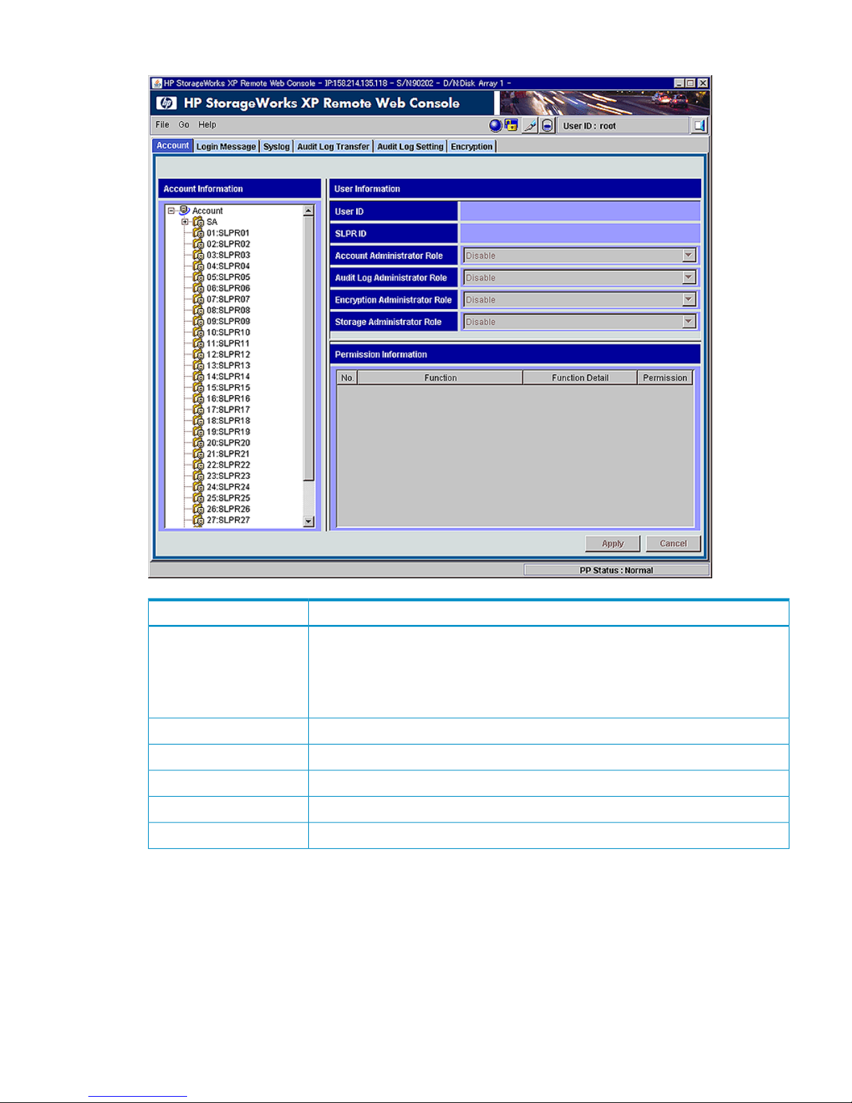
Figure 26 Remote Web Console Main Window
DescriptionItem
Displays the information about the connected storage system.
IP indicates the IP address of the SVP.
S/N indicates the serial number.
D/N indicates the device name specified in the Identity window.
Title bar
See “File Menu” (page 52).File menu
See “Go Menu” (page 53).Go menu
See “Help Menu” (page 54).Help menu
See “Extending the Modify Mode Timeout Period” (page 42).Reset button
See “Icons” (page 55).Icons
Common Elements of the Remote Web Console Main Windows 51
Page 52
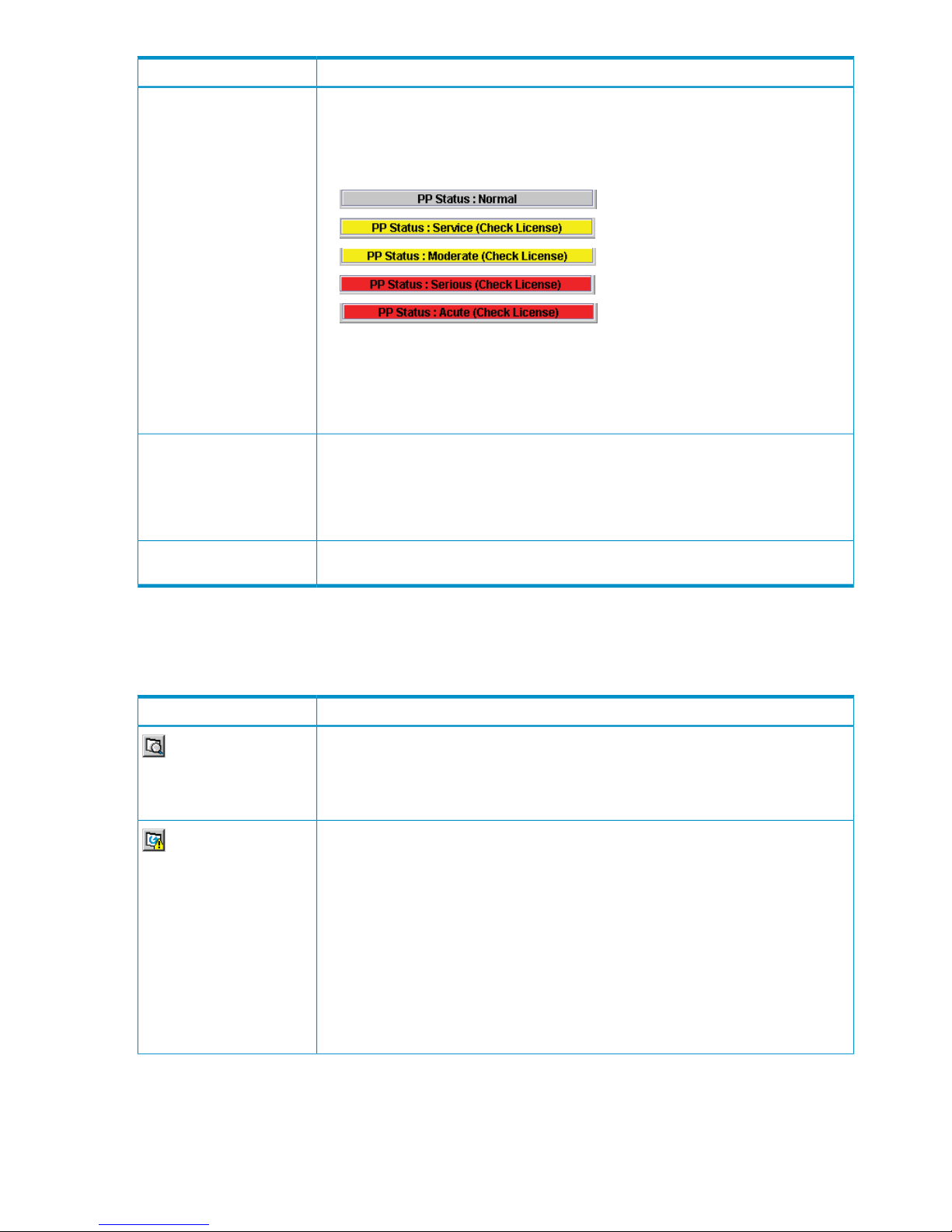
DescriptionItem
Displays the SIM severity level. PP Status is displayed if a SIM occurs related to a program
product license because the license is expired or the licensed capacity is insufficient.
However, only the storage administrator with the Storage Administrator role set to Enable
will be able to see the display.
PP Status can display any of the following SIM severity level statuses:
•
•
•
•
•
If PP Status : Normal is displayed, no SIM has occurred. If any other status is displayed,
view either the License Key window or the Alerts window to identify which program
product has a problem. You may find that you need to consider purchasing the license.
When multiple SIMs occur, only the SIM with the highest severity is displayed. For the
difference between SIM severity levels, see “Alerts Window” (page 67)).
PP Status
Implements all the changes or settings made on the Remote Web Console main window.
This button is available only in Modify mode.
If you make any changes, the text may be displayed in blue bold italics or an icon may
change (see “Text Color and Font Type Displayed on Windows” (page 29)). The changes
are not actually implemented until you click Apply.
Apply button
Cancels the changes or settings made on the Remote Web Console main window. This
button is available only in Modify mode.
Cancel button
File Menu
When you click the File menu, the following commands are displayed.
Table 20 File Menu Details
DescriptionItem
Opens the Reports Display dialog box, which displays the basic configuration information
on the storage system. The Reports Display dialog box is displayed as another window
apart from the Remote Web Console main window; therefore, it can be displayed
regardless of the operation of the Remote Web Console options. For details on the Reports
Display dialog box, see “Reports Display Dialog Boxes” (page 81).
Reports
Allows you to update the information on the SVP and then display the latest information
on the Remote Web Console main window. When you click this command, all information
displayed on Remote Web Console is reacquired from the storage system; therefore, it
takes time until the processing caused by this command has been completed.
The Refresh All command is available only when you log in as a storage administrator,
and becomes available when you change to Modify mode.
While the update processing caused by the Refresh All command is in progress, the
system status keeps changing and other users are not allowed to operate from the Remote
Web Console windows. Maintenance of the storage system or an SVP operation by an
HP service representative is not allowed either. Therefore, use of the Refresh All command
is not recommended unless error recovery is required.
The information may not display correctly if SVP maintenance is in progress.
Refresh All
52 Using the Remote Web Console GUI
Page 53
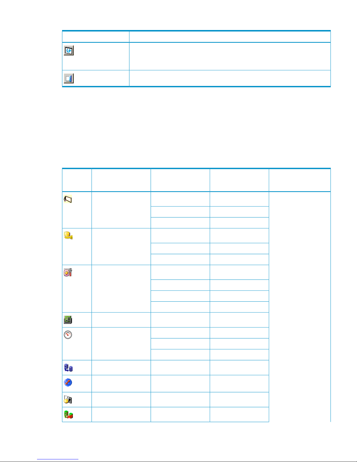
Table 20 File Menu Details (continued)
DescriptionItem
Displays the latest information on the Remote Web Console main window.
The information might not display correctly when the exclusive lock is in effect or SVP
maintenance is in progress.
Refresh
Closes the Remote Web Console main window.
Logout
Go Menu
The Go menu allows you to start the desired program product. When you click the Go menu, the
program product names and function names appear. Each name in the Go menu has a submenu
containing tab names of the corresponding program products or functions.
The contents of the Go menu differ depending on the operation privileges of the user account.
illustrates whether a storage partition administrator can perform each function. Table 21 (page
53) also illustrates operation privileges required to perform each function.
Table 21 Functions Available from the Go Menu
Operation Privileges
Required to Perform
Functions
Functions Available for
Storage Partition
Administrator
Tab NameItem in the Go MenuIcon
Storage Administrator roleView onlyIdentityDevice Status and Alerts
Not availablePort Status
Not availableAlerts
AvailableLU Path and SecurityLUN Manager
AvailablePort Mode
AvailableFC Authentication
AvailableLUN ExpansionVolume Manager
AvailableCustomized Volume
Not availablePool
Not availableV-VOL
AvailableCache ResidencyCache Residency
AvailablePerformance MonitorPerformance
Management
Not availableAuto LUN
Not availablePerformance Control
Not availableAll tabsContinuous Access
Not availableAll tabsContinuous Access
Journal
Not availableAll tabsBusiness Copy
Not availableAll tabsTrueCopy for Mainframe
Common Elements of the Remote Web Console Main Windows 53
Page 54
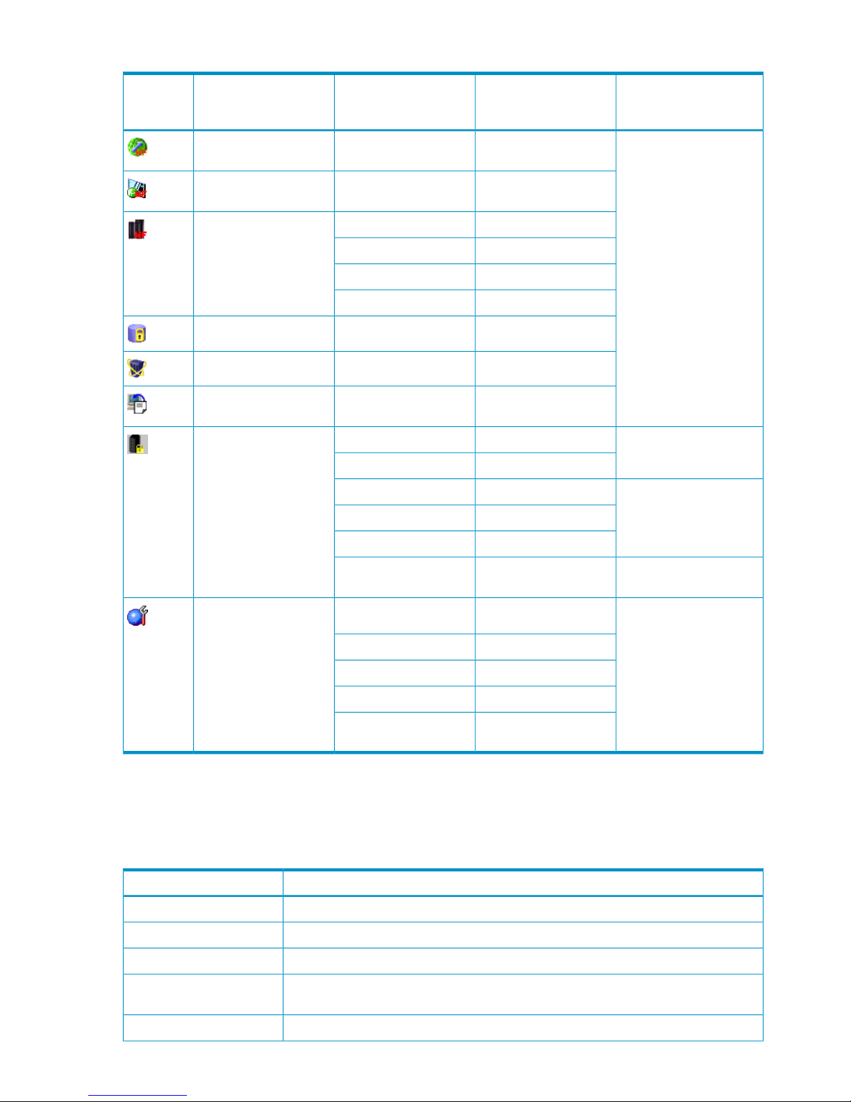
Table 21 Functions Available from the Go Menu (continued)
Operation Privileges
Required to Perform
Functions
Functions Available for
Storage Partition
Administrator
Tab NameItem in the Go MenuIcon
Not availableAll tabsUniversal Replicator for
Mainframe
Not availableAll tabsShadowImage for
Mainframe
Not availablePAVMainframe Connection
Not availableVolume Security
Not availableVolume Retention
Not availableXRC
AvailableData RetentionData Retention
Not availableExternal StorageExternal Storage
Not availableConfiguration File
Loader
Configuration File
Loader
Account Administrator roleAvailableAccountSecurity
Not availableLogin Message
Audit Log Administrator
role
Not availableSyslog
Not availableAudit Log Transfer
Not availableAudit Log Setting
Encryption Administrator
role
Not availableEncryption
Storage Administrator roleNot availableLicense KeyInstall
Not availableSNMP IP Security
Not availableE-mail Information
Not availablePartition Definition
Not availableLicense Key Partition
Definition
Help Menu
When you click the Help menu, the About command is available. The About command opens the
About dialog box, which displays storage system information.
Table 22 About Dialog Box Details
DescriptionItem
Product name of the connected storage system.Subsystem
Serial number of the connected storage system.Serial Number
IP address of the connected storage system (SVP).IP Address
Device name of the connected storage system that you set in the Identity window (see
“Device Information” (page 62)).
Device Name
Contact information that you set in the Identity window.Contact
54 Using the Remote Web Console GUI
Page 55
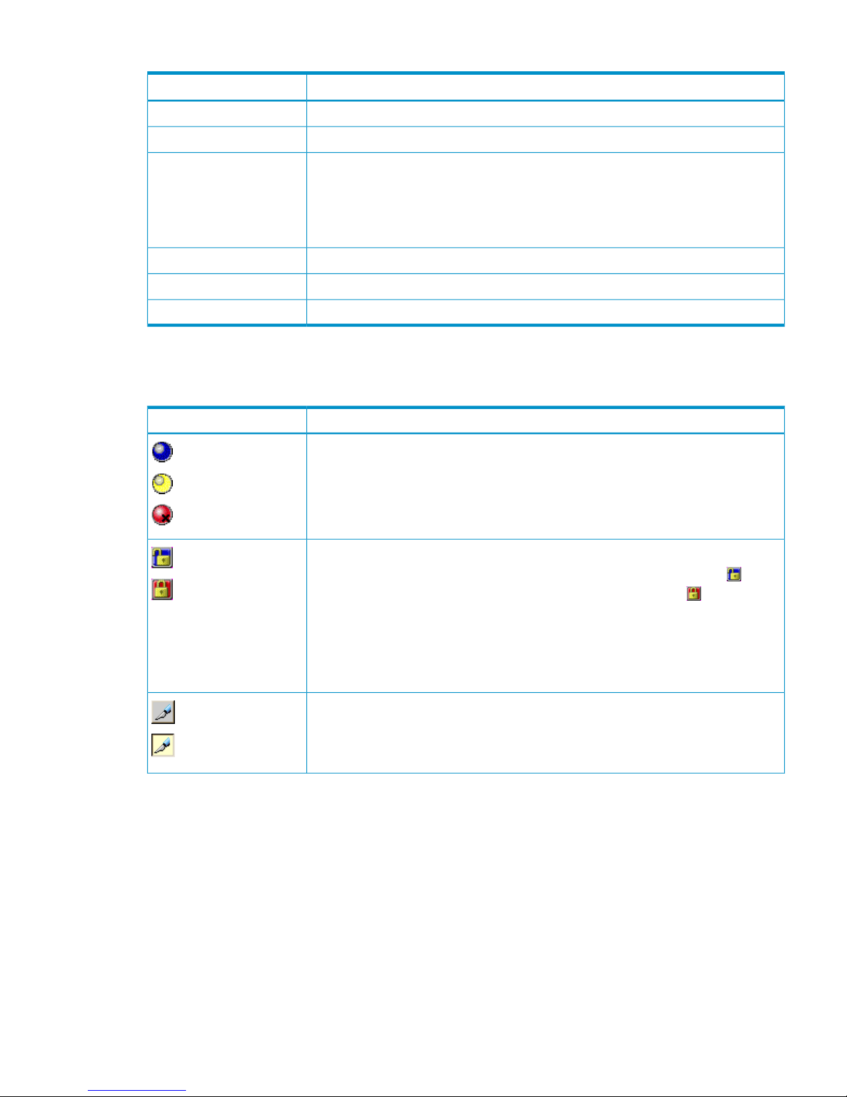
Table 22 About Dialog Box Details (continued)
DescriptionItem
Location of the connected storage system that you set in the Identity window.Device Location
Version of the microcode installed in the connected storage system.Main Version
Version of the Remote Web Console Java application program installed in the SVP of
the connected storage system.
The Java application program is downloaded each time the Remote Web Console
computer connects to the SVP, so that the version is always consistent between the Remote
Web Console computer and SVP.
SVP Version
Version of the RMI server installed in the SVP of the connected storage system.Server Version
Opens the Hewlett-Packard website.Home Page
Opens of the website for the Remote Web Console manuals.Documentation Home Page
Icons
The following icons appear on the Remote Web Console main window.
DescriptionItem
Indicates the storage system error status by color (blue: normal, yellow: warning, red:
abnormal) according to the host SIM status. For details, check the Alerts window (see
“Alerts Window” (page 67)).
Normal
Warning
Abnormal
Indicates the operation mode of all currently logged-in users.
If all users are viewing the information in View mode, the blue unlocked icon ( ) is
displayed. If a user is operating in Modify mode, the red locked icon ( ) is displayed.
The status might not be displayed correctly while an SLPR is locked and being modified
by a storage partition administrator or SVP maintenance is in progress.
One storage partition administrator for each SLPR can change to Modify mode. While
a storage administrator is in Modify mode, any other storage partition administrator
cannot change to Modify mode.
Unlocked
Locked
Allows users to switch the operation mode between Modify and View. The button always
shows the current user operation mode. To change the mode, click the button.
You cannot switch to Modify mode while any other user is operating in Modify mode.
Make sure to confirm the exclusive lock icon before switching to Modify mode.
View
Modify
Common Elements of the Remote Web Console Main Windows 55
Page 56

DescriptionItem
Allows you to download the audit log file.
• When the lines of saved data in the audit log file are under the threshold, the
Audit:Normal button is displayed.
• When the lines of saved data in the audit log file exceed the threshold, the
Audit:Warning button is displayed.
• When the lines of saved data in the audit log file have exceeded the threshold and
reached the maximum number of lines that can be saved, the Audit:Wraparound
button is displayed.
To use these buttons to download the audit log file, you need to log in with the user
account of a storage administrator. The Audit Log Administrator role needs to be set to
Modify or View for setting the operation privileges for the user account. For detailed
information on the audit log file, see the HP StorageWorks XP24000/XP20000 Audit
Log User and Reference Guide.
After the FTP server settings are completed, the Audit:Warning button or the
Audit:Wraparound button might still be displayed on the Remote Web Console main
window. This is due to a transfer failure of the audit log file. See “Audit Log Transfer
Window” (page 74) for instructions on how to resolve the problem.
Audit:Normal
Audit:Warning
Audit:Wraparound
Shows the user ID of the currently logged-in user. When you have logged in as a storage
partition administrator, the SLPR number and name are displayed to the right of the user
ID in the format < SLPR number : SLPR name>.
User ID
Closes the Remote Web Console main window.
Logout
License Key Window
The License Key window allows you to install and uninstall storage system options for the connected
storage system. The License Key window displays a list of storage system options, and allows you
to enter the license key code for a desired option. For detailed operations on the License Key
window, see “Enabling and Disabling Remote Web Console Options” (page 97).
To open the License Key window, log in to the Remote Web Console, and then select Go, Install,
and License Key from the menu bar of the Remote Web Console main window. If no Remote Web
Console options have been installed, this window opens automatically when you log in to the SVP.
If storage partition administrators want to use the program product options for their own SLPRs,
the program product options have to be installed by the storage administrators from the License
Key window, and then the licensed capacity for each program product option has to be allocated
to SLPRs by the storage administrators from the License Key Partition Definition window. For a
description of the License Key Partition Definition window and the procedure for allocating licensed
capacity to the SLPRs, see the HP StorageWorks XP24000/XP20000 Disk/Cache Partition User
Guide.
56 Using the Remote Web Console GUI
Page 57
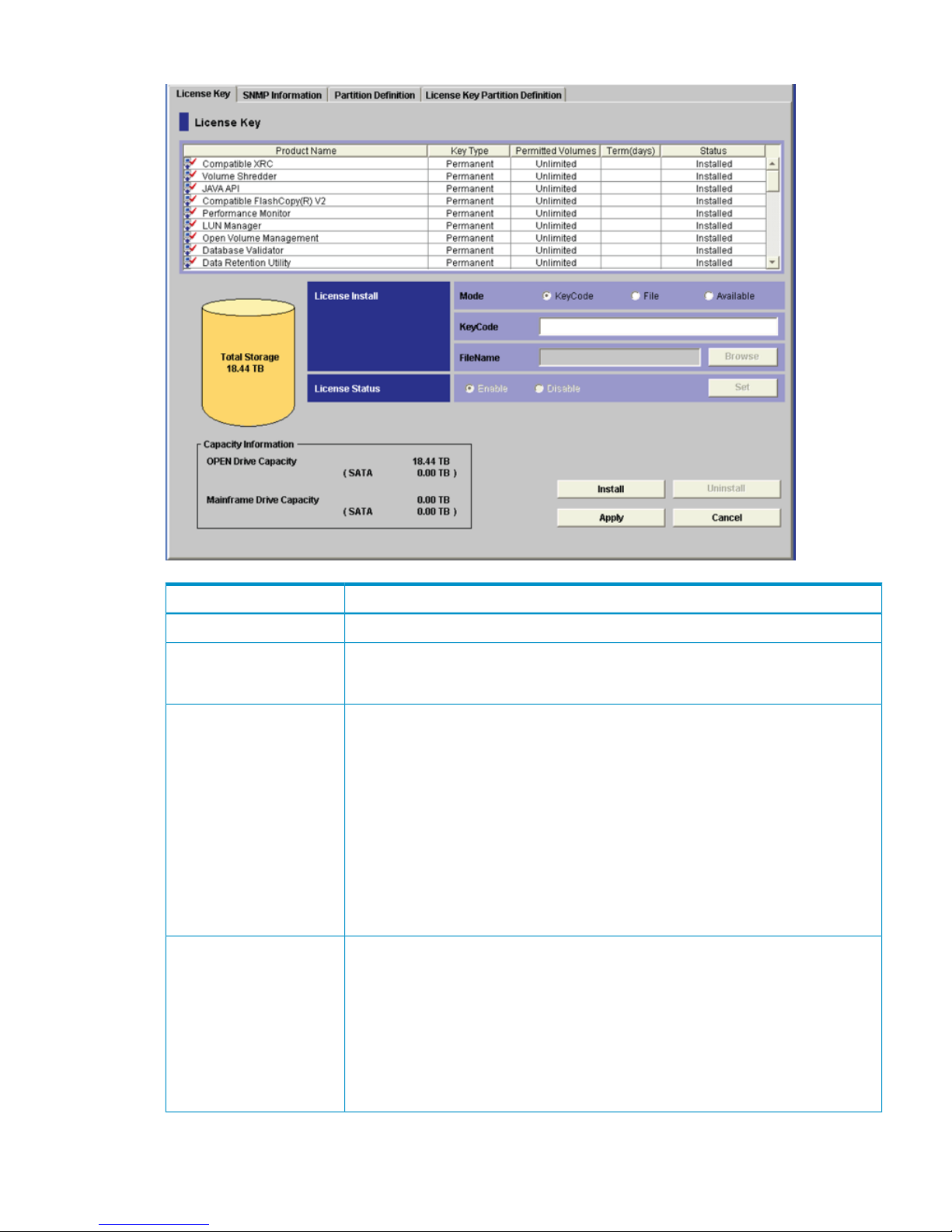
Figure 27 License Key Window
DescriptionItem
See “License Key List” (page 58).License Key list
The Total Storage graphic on the left side of the License Key window displays the total
volume capacity currently available in the storage system (open and mainframe drive
capacity; not including external storage capacity).
Total Storage
Allows you to select one of the following modes for installing a license key:
• When Key Code mode is selected, use the Key Code text box to type the license key
code for the selected option to be installed (see “Enabling Options Using a License
Key Code” (page 97)). You cannot copy and paste text from other applications.
• When File mode is selected, use the File Name text box or the Browse button to enter
the name of the license key file (see “Enabling Options Using a License Key File”
(page 98)). When you click Browse, a dialog box opens, allowing you to select the
desired license key file.
• When Available mode is selected, you can install available options automatically.
The Available button can be used only when the licensed capacity exceeds the mounted
(or used) capacity because the disk drives are reduced or because the pairs are
deleted by a program product such as XP Continuous Access.
License Install
Allows you to enable or disable each program product option listed in the License Key
list. Select a program product option from the License Key list, select Enable or Disable,
and click Set.
• Enable: You can use the program product option. If you enable an option with the
term key, the available days of the term key will decrease by one day when you set
Enable. When the setting is applied, Installed appears.
• Disable: You cannot use the program product option. If you disable an option with
the term key, the available days of the term key will not decrease when you set Disable.
When the setting is applied, Installed (Disable) appears.
License Status
License Key Window 57
Page 58

DescriptionItem
OPEN Drive Capacity displays the capacity of open-system drives in Total Storage.
Mainframe Drive Capacity displays the capacity of the mainframe drives in Total Storage.
The capacity of the SATA or the flash drive in each capacity is displayed in parentheses.
SSD in Figure 27 (page 57) refers to flash drive.
Capacity Information
Changes the row of the selected option or the options that can be installed using the
Available button to blue bold italics, and also changes the displayed status to Install.
The options are not actually installed until you click Apply.
Install button
Changes the row of the selected option to blue bold italics, and also changes the
displayed status to Uninstall. The options are not actually uninstalled until you click Apply.
Uninstall button
Implements the settings made using Install or Uninstall to the storage system. The status
of installed options changes to Installed, and the status of uninstalled option changes to
Not Installed.
Apply button
Cancels the settings made using the Install or Uninstall button.Cancel button
License Key List
The License Key list, across the top of the License Key window, has the following features:
DescriptionItem
The name of the product, including:
• Option name
• Icon that indicates whether the option is available ( indicates Installed; indicates
Not Installed)
Product Name
The license type:
• Permanent
• Term
• Temporary
• Emergency
• Not Installed (when no license key is installed)
Key Type
The column shows the following information:
XXTB(YYTB)
where
XX is the available capacity (licensed capacity).
YY is the capacity that is already being used by XP Continuous Access,
XP Business Copy, Volume Retention Manager, and Data Retention
Utility.
For example, if this column displays 10.0TB (2.50TB), the licensed capacity is 10.0 TB
and the capacity already being used is 2.50 TB.
If the size is unlimited, Unlimited is displayed in this column.
Licensed capacities are calculated assuming that 1 KB = 1,024 bytes, 1 MB = 1,024
KB, 1 GB = 1,024 MB, and 1 TB = 1,024 GB.
Permitted Volumes
58 Using the Remote Web Console GUI
Page 59
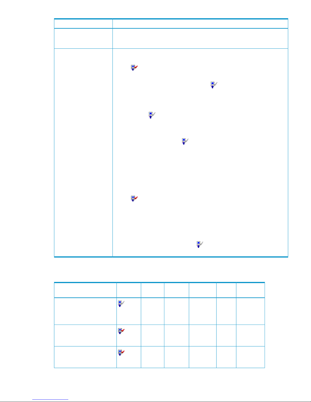
DescriptionItem
The number of days that remain before the expiration of a temporary key, an emergency
key, or a term key. After the temporary key has expired, the number of days that remain
before you can re-install the temporary key is displayed.
Term (days)
The current status of an option:
• Installed: The option is available. The Product Name column displays the Installed
icon ( ).
• Installed (Disable): Installation is complete, but the license is set to disable. The Product
Name column displays the Not Installed icon ( ).
This status might be displayed if an error occurs after you install options. Resolve the
error and enable the license.
• Not Installed: The option is not available. The Product Name column displays the Not
Installed icon ( ).
• Not Enough: Installation is complete, but the license capacity is insufficient. This status
is also displayed when the license key of this program product is installed but the
license key of the prerequisite program product is expired. The Product Name column
displays the Not Installed icon ( ).
Not Enough might remain displayed when the licensed capacity exceeds the mounted
capacity after you reduce the number of hard disk drives, or when the licensed capacity
exceeds the used capacity after you delete pairs or pools. In these cases, you can
install the available program products by following the procedure in “Enabling Options
Automatically” (page 99).
• Capacity Insufficient: The licensed capacity is insufficient because hard disk drives
are added or pairs have been created by a program product such as XP Continuous
Access. The license expires in 30 days. The Product Name column displays the Installed
icon ( ). Purchase the license before the license key expires.
Capacity Insufficient might remain displayed when the licensed capacity exceeds the
mounted capacity after you reduce the number of hard disk drives, or when the
licensed capacity exceeds the used capacity after you delete pairs or pools. In these
cases, you can install the available program products by following the procedure in
“Enabling Options Automatically” (page 99).
• Time Out: The term has already expired for the temporary key. The Product Name
column displays the Not Installed icon ( ). When the status is Time Out, you cannot
re-install the temporary key.
Status
Table 23 (page 59) explains the status and icons on the License Key list.
Table 23 License Key Status and Icons
StatusTerm
(days)
Permitted
Volume
Key TypeProduct
Name
1
IconLicense Key Status
Not Installed––Not
Installed
Option
name
(Not
Installed)
Not installed.
Installed–Unlimited or
X TB
2
PermanentOption
name
(Installed)
Installed with the Permanent
key.
Installed
3
Unlimited or
X TB
2
TermOption
name
(Installed)
Installed with the Term key and
set to enable.
License Key Window 59
Page 60

Table 23 License Key Status and Icons (continued)
StatusTerm
(days)
Permitted
Volume
Key TypeProduct
Name
1
IconLicense Key Status
Installed
(Disable)
–Unlimited or
X TB
2
TermOption
name
(Not
Installed)
Installed with the Term key and
set to disable.
Installed
3
–TemporaryOption
name
(Installed)
Installed with the Temporary
key.
Installed
3
–EmergencyOption
name
(Installed)
Installed with the Emergency
key.
Time Out
3
–TemporaryOption
name
(Not
Installed)
A Temporary key was
installed, but has expired.
Not Installed––Not
Installed
Option
name
(Not
Installed)
A Term key or an Emergency
key was installed, but has
expired.
Not Enough–X TB
2
Permanent
or Term
Option
name
(Not
Installed)
Installed with the Permanent
key or the Term key, but the
licensed capacity was
insufficient.
Capacity
Insufficient
3
X TB
2
Permanent
or Term
Option
name
(Installed)
The capacity insufficiency
caused by PDEV expansion.
Installed
3
X TB
2
TemporaryOption
name
(Installed)
Installed with the Temporary
key, and then reinstalled with
the Permanent key, but the
license capacity was
insufficient.
Installed
3
Unlimited or
X TB
2
EmergencyOption
name
(Installed)
Installed with the Permanent
key, then reinstalled with the
Emergency key.
1 See “Remote Web Console Options and Licensed Capacity” (page 47) for option names.
2 X TB (Y TB) appears for program products for which you will be charged for the capacity that you use. X indicates the
licensed capacity, and Y indicates the used capacity.
3 The Term column shows the number of days remaining before program product expiration.
– indicates that nothing is displayed.
License Install Box
License Install is on the right side of the License Key window.
60 Using the Remote Web Console GUI
Page 61

License Install has the following features:
• Mode allows you to select one of the following buttons: the Key Code button, the File button,
or the Available button.
◦ Key Code enables the Key Code text box, which allows you to enter the license key for
the selected option to be installed (see “Enabling Options Using a License Key Code”
(page 97)).
NOTE: You cannot copy and paste text from other applications.
◦ File enables the File Name text box and the Browse button, which allow you to enter the
name of the desired license key file (see “Enabling Options Using a License Key File”
(page 98)). When you select the Browse button, the dialog box to select the license key
file is displayed. As you select the desired license key file on the displayed dialog box,
you can enter the license key file name in the File Name text box.
◦ Available enables you to install available options automatically. The Available button can
be used only when the licensed capacity exceeds the mounted (or used) capacity because
the disk drives are reduced, or because the pairs are deleted by a program product such
as TrueCopy for Mainframe.
License Status Box
License Status is on the bottom right of the License Key window.
You can set the license to enable or disable for each program product option listed in the license
key list. If you select a program product option from the license key list, select one of the following
options, and then click Set, you can set the option to enable or disable.
• Enable: You can use the program product option.
If you set an option to Enable with the term key, the available days of the term key decrease
by one day. When the setting is applied, Installed is displayed.
• Disable: You cannot use the program product option.
If you set an option to Disable with the term key, the available days of term key will not
decrease. When the setting is applied, Installed (Disable) is displayed.
Identity Window
The Identity window displays information on the connected storage system.
To open the Identity window, log in to the Remote Web Console, and then click Go, Device Status
and Alerts and Information on the menu bar of the Remote Web Console main window. A storage
partition administrator can view the Identity window, but cannot change the information on the
Identity window.
Identity Window 61
Page 62
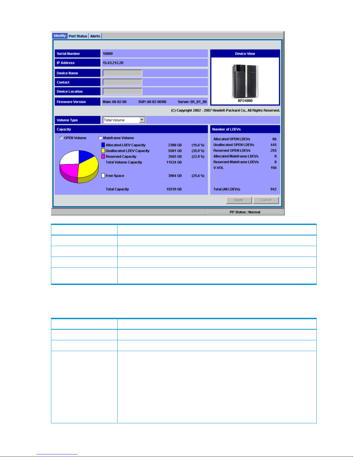
Figure 28 Identity Window
DescriptionItem
See “Device Information” (page 62).Device Information
See “LDEV Information” (page 63).LDEV Information
Implements all the changes or settings. This button is active only in Modify mode.Apply button
Closes the window without making changes or settings. This button is available only in
Modify mode.
Cancel button
Device Information
Device Information, in the upper part of the Identity window, has the following features:
DescriptionItem
Serial number of the connected storage system.Serial Number
IP address of the connected storage system (SVP).IP Address
Device name of the connected storage system. The Remote Web Console user can change
the device name with Modify mode.
Enter a device name using up to 180 alphanumeric characters (ASCII codes), except for
some symbols, such as ", \, ;, :, ,, *, ?, <, >, |, /, ^, &, and %. You can also use a
space, except for before and after the device name. If you enter a space before or after
the device name, an error occurs when you click Apply. The device name is required to
use SNMP Agent. For detailed information on SNMP, see the HP StorageWorks
XP24000/XP20000 SNMP Agent Reference Guide.
Make sure to document the device name because the settings will be cleared when the
SVP is replaced.
Device Name
62 Using the Remote Web Console GUI
Page 63

DescriptionItem
Contact information such as personnel and telephone number where you can inquire
about the connected storage system. The Remote Web Console user can change the
contact information with Modify mode.
Enter the contact information using up to 180 alphanumeric characters (ASCII codes),
except for some symbols, such as ", \, ;, :, ,, *, ?, <, >, |, /, ^, &, and %. You can also
use a space, except for before and after the contact information. If you enter a space
before or after the contact information, an error occurs when you click Apply. The contact
name is required to use SNMP Agent. For detailed information on SNMP, see the HP
StorageWorks XP24000/XP20000 SNMP Agent Reference Guide.
Make sure to document the contact name because the settings will be cleared when the
SVP is replaced.
Contact
Location of the connected storage system. The Remote Web Console user can change
the device location with Modify mode.
Enter a device location using up to 180 alphanumeric characters (ASCII codes), except
for some symbols, such as ", \, ;, :, ,, *, ?, <, >, |, /, ^, &, and %. You can also use
a space, except for before and after the location. If you enter a space before or after
the location, an error occurs when you click Apply. The device location is required to
use SNMP Agent. For detailed information on SNMP, see the HP StorageWorks
XP24000/XP20000 SNMP Agent Reference Guide.
Make sure to document the device location because the settings will be cleared when
the SVP is replaced.
Device Location
Provides the firmware version information for the connected storage system:
• Main: Version of the microcode installed in the connected storage system.
• SVP: Version of the Remote Web Console Java application installed in the SVP of the
connected storage system.
• Server: Version of the RMI server installed in the SVP of the connected storage system.
Firmware Version
Product name and visual image (picture) of the connected storage system.Device View
LDEV Information
LDEV Information, on the lower part of the Identity window (see Figure 29 (page 64)), provides
information about the LDEV. If you have logged in as a storage partition administrator, information
about the allocated SLPR is displayed instead of for the whole storage system.
Identity Window 63
Page 64
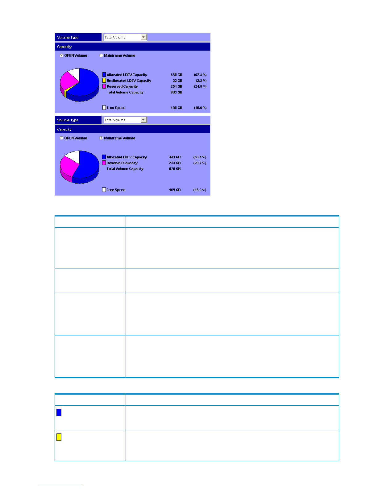
Figure 29 Volume Type and Capacity in LDEV Information
Table 24 LDEV Information Details
DescriptionItem
Allows you to select the type of volume capacity information from the Volume Type list:
• Total Volume: Information on all the volumes.
• Internal Volume Only: Information on only the internal volumes.
• External Volume Only: Information on only the external volumes.
Volume Type
Provides the capacities in MB when the Total Volume Capacity is 10 GB or less, and in
GB when the Total Volume Capacity is more than 10 GB. The percentages (%) of the
capacities relative to total capacity are shown in parentheses.
Capacity
When selected, shows the volume capacity information (capacity by volume type, pie
chart, total capacity) on open-system volumes in the storage system. The information does
not include the capacity of the V-VOL. When there is no open-system volume, No Volume
appears.
See Table 25 (page 64) for the capacity pie chart when OPEN Volume is selected.
OPEN Volume
When selected, shows the volume capacity information (capacity by volume type, pie
chart, total capacity) on zSeries, S/390 (mainframe), and multiplatform volumes in the
storage system. The information shown does not include the capacity of the V-VOL. When
there is no zSeries and S/390 volume, No Volume appears.
See Table 26 (page 65) for the capacity pie chart when Mainframe Volume is selected.
Mainframe Volume
Table 25 Open Volume Capacity Pie Chart
DescriptionItem
The capacity of open-system volumes (LDEVs) that have assigned paths and are available
to the user. This capacity also includes all LDEVs that consist of LUSE volumes, but does
not include control cylinders. This capacity is indicated in the pie chart by the blue area.
Allocated LDEV Capacity
The capacity of open-system volumes (LDEVs) that do not have assigned paths and are
available to the user. This capacity does not include control cylinders, reserved volumes
of XP Auto LUN, journal volumes, pool volumes, system disks, or quorum disks. This
capacity is indicated in the pie chart by the yellow area.
Unallocated LDEV
Capacity
64 Using the Remote Web Console GUI
Page 65

Table 25 Open Volume Capacity Pie Chart (continued)
DescriptionItem
The capacity of the following volumes among open volumes (LDEVs). This capacity does
not include reserved volumes of XP Business Copy.
• Reserved volumes of XP Auto LUN (for information on XP Auto LUN, see the HP
StorageWorks XP24000/XP20000 Auto LUN Software User Guide)
• Journal volumes (see the Hitachi Universal Replicator™ for Mainframe User Guide:
HP XP24000 Disk Array, HP XP20000 Disk Array)
• Pool volumes (see the HP StorageWorks XP24000/XP20000 Snapshot User Guide
or HP StorageWorks XP24000/XP20000 Thin Provisioning Software User Guide)
• System disks (see the HP StorageWorks XP24000/XP20000 Virtual LVI/LUN (VLL)
and Volume Shredder User Guide)
• Quorum disks (see the HP StorageWorks XP24000/XP20000 External Storage
Software User Guide)
This capacity is indicated in the pie chart by the pink area.
Reserved Capacity
The sum of allocated, unallocated, and reserved volume capacities.Total Volume Capacity
Free space available for configuring open-system volumes (LDEVs). This is indicated in
the pie chart by the white area.
Free Space
Table 26 Mainframe Volume Capacity Pie Chart
DescriptionItem
The capacity of zSeries, S/390, and multiplatform volumes (LDEVs) that have assigned
paths and are available to the user. This capacity does not include reserved volumes of
XP Auto LUN, journal volumes, system disks, or quorum disks. This capacity is displayed
in the pie chart by the blue area.
Allocated LDEV Capacity
The capacity of the following volumes among zSeries, S/390, and multiplatform volumes
(LDEVs). This capacity does not include reserved volumes of ShadowImage for Mainframe.
• Reserved volumes of XP Auto LUN (for information on XP Auto LUN, see the HP
StorageWorks XP24000/XP20000 Auto LUN Software User Guide)
• Journal volumes (see the Hitachi Universal Replicator™ for Mainframe User Guide:
HP XP24000 Disk Array, HP XP20000 Disk Array)
• System disks (see the HP StorageWorks XP24000/XP20000 Virtual LVI/LUN (VLL)
and Volume Shredder User Guide)
• Quorum disks (see the HP StorageWorks XP24000/XP20000 External Storage
Software User Guide)
This capacity is indicated in the pie chart by the pink area.
Reserved Capacity
The sum of allocated and reserved volume capacities.Total Volume Capacity
Free space that users can use for configuring zSeries, S/390, and multiplatform volumes
(LDEVs). This is displayed in the pie chart by the white area.
Free Space
Number of LDEVs
Number of LDEVs, on the lower right of the Remote Web Console main window, has the following
features.
Identity Window 65
Page 66

Table 27 Number of LDEVs Details
DescriptionItem
The number of open-system volumes (LDEVs) that have assigned paths. Each of the LDEVs
that consist of a LUSE volume is counted as one volume.
Allocated OPEN LDEVs
The number of open-system volumes (LDEVs) that do not have assigned paths. This number
does not include reserved volumes of XP Auto LUN, journal volumes, pool volumes, system
disks, or quorum disks.
Unallocated OPEN LDEVs
The number of reserved volumes of XP Auto LUN, journal volumes, pool volumes, system
disks, and quorum disks among open-system volumes (LDEVs). This number does not
include reserved volumes of XP Business Copy.
Reserved OPEN LDEVs
The number of zSeries, S/390, and multiplatform volumes (LDEVs) that have assigned
paths. This number does not include reserved volumes of XP Auto LUN, journal volumes,
pool volumes, system disks, or quorum disks.
Allocated Mainframe LDEVs
The number of reserved volumes of XP Auto LUN, journal volumes, system disks, and
quorum disks among zSeries, S/390, and multiplatform volumes (LDEVs). This number
does not include reserved volumes of ShadowImage for Mainframe.
Reserved Mainframe LDEVs
The number of V-VOLs that are virtual volumes (LDEVs) that do not consume the actual
disk capacity. V-VOLs are currently used for XP Snapshot and XP Thin Provisioning. For
details, see the HP StorageWorks XP24000/XP20000 Snapshot User Guide or the HP
StorageWorks XP24000/XP20000 Thin Provisioning Software User Guide.
V-VOL
The sum of allocated OPEN LDEVs, unallocated OPEN LDEVs, reserved OPEN LDEVs,
allocated Mainframe LDEVs, reserved Mainframe LDEVs, and V-VOLs.
Total (All LDEVs)
Port Status Window
The Port Status window displays the port information using the image of the ports mounted on the
storage system.
To open the Port Status window, log in to the Remote Web Console, and then select Go, Device
Status and Alerts and Port Status from the menu bar of the Remote Web Console main window.
Storage partition administrators cannot display the Port Status window.
66 Using the Remote Web Console GUI
Page 67
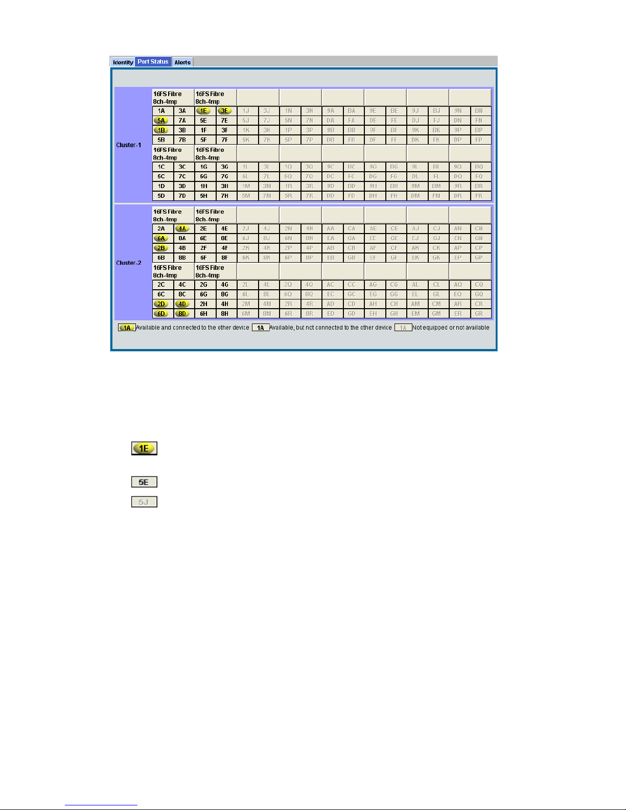
Figure 30 Port Status Window
Cluster-1 and Cluster-2 in the Port Status window indicate the clusters. The ports of Cluster-1 are
listed on the upper part, and the ports of Cluster-2 are listed on the lower part of the Port Status.
Each cluster has up to 16 PCBs and the name of each PCB is displayed on the header of the port
list. The icons show the port name, port LED status, and equipment information for the port. The
icons indicate the following information:
• : This port is equipped and currently used. The cable is properly set. This port is available
for the operation.
• : This port is equipped and available for the operation.
• : This port is not equipped or not available.
Alerts Window
The Alerts window displays the internal status (according to the SIM information reported to the
host) of the connected storage system. The storage system generates a SIM whenever it detects an
error or service requirement.
The status history is listed in the Alerts list on the Alerts window. The icon displayed in the upper
right of the Remote Web Console main window indicates the error level of the disk controller status
or the disk array unit status. The icon indicates one or more severe errors.
To open the Alerts window, log in to the Remote Web Console, and then select Go, Device Status
and Alerts and Alerts from the menu bar of the Remote Web Console main window. Storage
partition administrators cannot display the Alerts window.
Alerts Window 67
Page 68
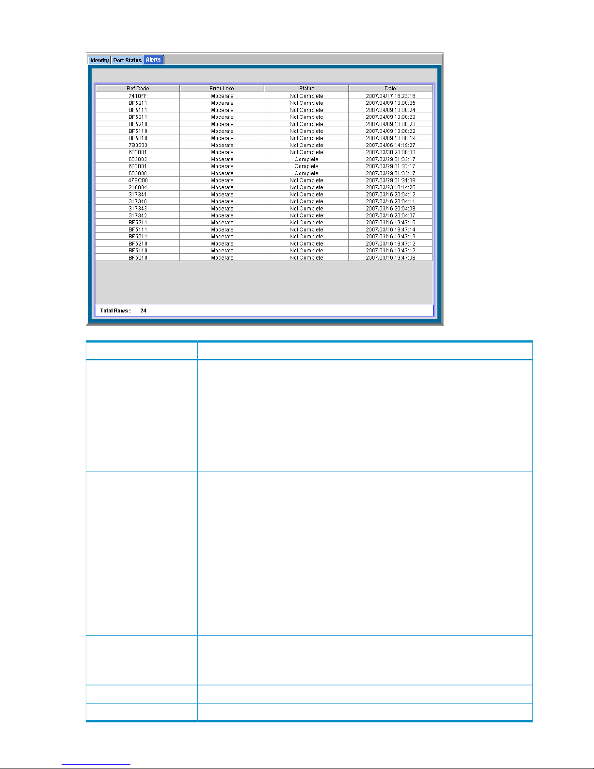
Figure 31 Alerts Window
DescriptionItem
SIM reference code. When SIM reference codes are shown, you are required to resolve
the error. For details on how to resolve the error, see the HP StorageWorks
XP24000/XP20000 Snapshot User Guide or the HP StorageWorks XP24000/XP20000
Thin Provisioning Software User Guide.
The reference codes are:
• 601XXX and 602XXX (for XP Snapshot)
• 620XXX, 621XXX, 622XXX, 623XXX, and 630XXX (for XP Thin Provisioning)
where XXX indicates the pool ID.
Ref. Code
The error level. When the status becomes other than Good, all SIMs must be completed
(resolved) from the SVP to restore the status to Good.
• Good: No error occurs and the status is good.
• Service: Does not require immediate attention and can be addressed during routine
maintenance.
• Moderate: Does not require immediate attention and can be addressed during routine
maintenance.
• Serious: Contact HP technical support. Follow up with technical support to verify that
the problem has been resolved. See “Troubleshooting” (page 132) for further
information.
• Acute: Contact HP technical support. Follow up with technical support to verify that
the problem has been resolved. See “Troubleshooting” (page 132) for further
information.
Error Level
Status of the SIM.
• Complete: The SIM has been deleted from the SVP.
• Not Complete: The SIM has not been deleted.
Status
The date that the SIM occurred.Date
The total number of rows that are listed.Total Rows
68 Using the Remote Web Console GUI
Page 69
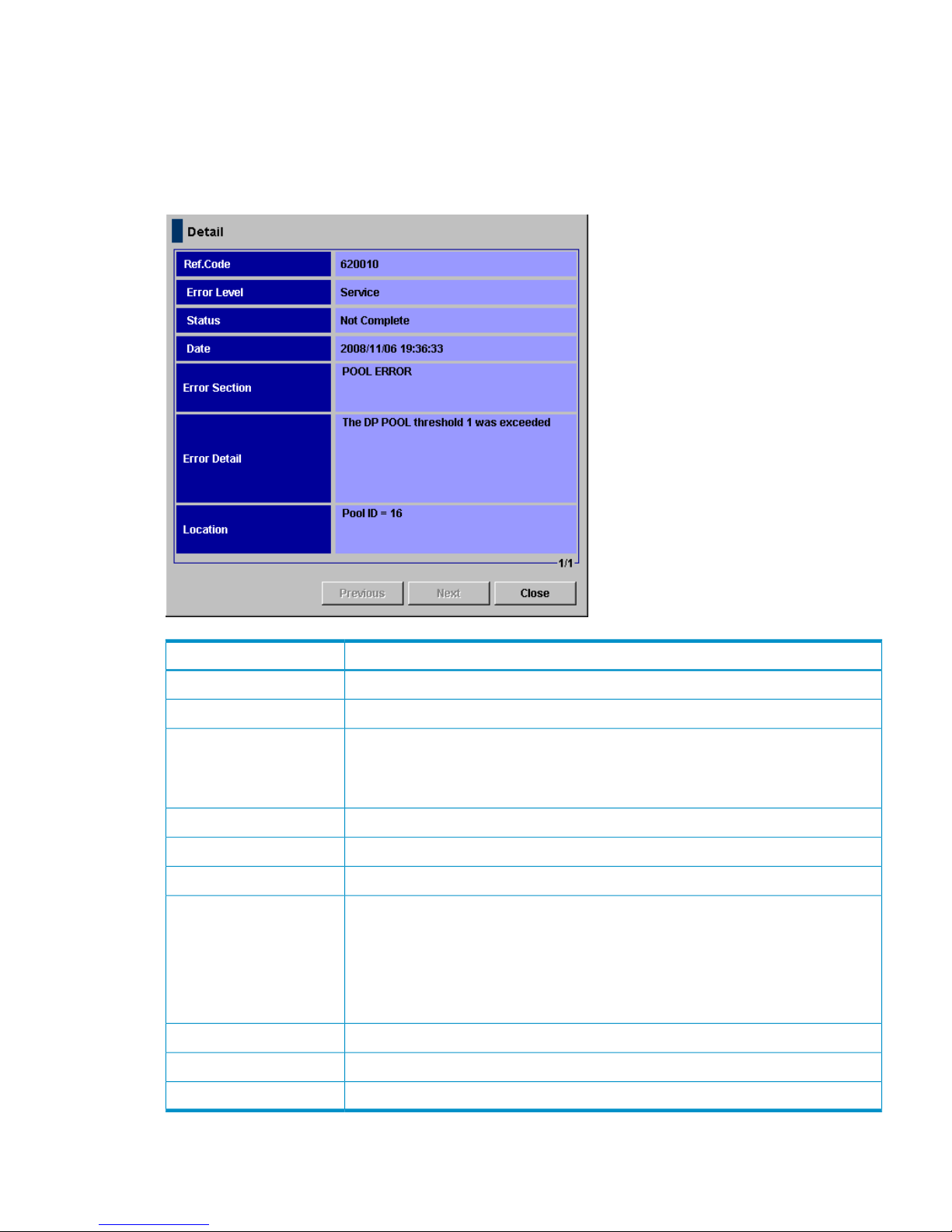
Detail Dialog Box
When you select a row in the Alerts list, right-click, and select the Detail command, the Detail
dialog box (see Figure 32 (page 69)) opens with detailed information on the error. In addition to
the information provided on the Alerts list, the Detail dialog box provides the Error Section, Error
Detail, and Location for the selected row.
Figure 32 Detail Dialog Box
DescriptionItem
SIM reference code.Ref.Code
Error level.Error Level
Status of the SIM.
• Complete: The SIM has been deleted from the SVP.
• Not Complete: The SIM has not been deleted.
Status
The date that the SIM occurred.Date
The section of the selected row where the error occurred.Error Section
More detail on the error of the selected row.Error Detail
Displays the pool number by decimal notation according to the reference code:
• 601XXX or 602XXX (for XP Snapshot)
• 620XXX, 621XXX, 622XXX, 623XXX, or 630XXX (for XP Thin Provisioning)
where XXX indicates the pool ID.
This area displays [ - ] for any other codes.
Location
Provides information on the previous row.Previous button
Provides information on the next row.Next button
Closes the dialog box.Close button
Alerts Window 69
Page 70
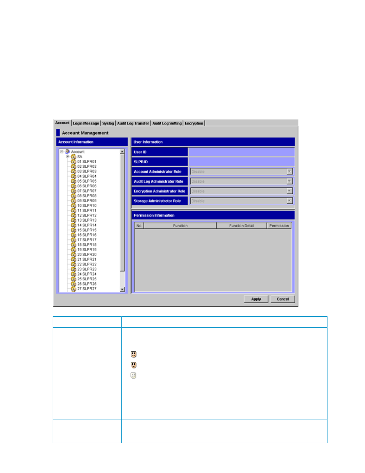
Account Window
The Account window allows you to register new user accounts or view and change the settings of
the registered user accounts. The operations that can be performed in the Account window differ
depending on the operation privileges set for the Account Administrator role.
To open the Account window, log in to the Remote Web Console, and then select Go, Security
and Account from the menu bar of the Remote Web Console main window.
This section describes the components of the Account window. For information on operations that
can be performed from the Account window, see “Managing the User Accounts” (page 101). For
information on user accounts of Remote Web Console, see “User Access Levels” (page 9).
Figure 33 Account Window
DescriptionItem
Lists the registered user IDs. The SA folder lists all user IDs of storage administrators. The
SLPR folders that are numbered from 01 to 31 list all user IDs of storage partition
administrators registered in each SLPR.
• indicates your user ID
• indicates other user IDs
• indicates disabled user IDs
To register new user accounts, start the operation from the Account Information tree. You
register the user accounts of storage administrator into the SA folder, and you register
the user accounts of storage partition administrator into a folder with the appropriate
SLPR number and name. For the procedure to register new user accounts, see “Registering
New Users” (page 101).
Account Information tree
Shows the setting of the user account you select in the Account Information tree. With
the proper privileges, you can edit and view the privileges of registered user accounts
on User Information.
User Information
70 Using the Remote Web Console GUI
Page 71

DescriptionItem
Displays the user ID that is set when the user account has been registered.User ID
Indicates the user account type.
• SA: indicates a storage administrator.
• Number: Name indicates a storage partition administrator, with the SLPR number and
name displayed.
SLPR ID
The user account operation privilege. The available settings are Disable, View, and
Modify. The Account Administrator role of the administrator user ID cannot be changed.
Account Administrator Role
The audit log operation privilege. The available settings are Disable, View, and Modify.
The Audit Log Administrator role of a storage partition administrator cannot be changed.
Audit Log Administrator Role
The operation privilege to encrypt data in volumes in the storage system. The available
settings are Disable and Enable. The Encryption Administrator role of a storage partition
administrator cannot be changed.
Encryption Administrator
Role
The storage operation privilege. The available settings are Disable and Enable. The
Enable setting allows you to set the privileges for each program product operation. You
need to set Enable to validate the privileges for each program product operation.
Storage Administrator Role
Shows the setting of the user account you select in the Account Information tree.
To set Modify or View for program products, right-click a row (or rows) of a function,
then click Modify or View.
Permission Information list
Serial number of the Permission Information list.No.
The lists of the program products and functions. For the storage partition administrators,
the available functions are less than those of storage administrators’. For details on
functions that storage partition administrators can use, see “Go Menu” (page 53).
Function and Function Detail
The access level for each function.
• Modify: Allows you to perform the selected operation.
• View: Allows you to view the information, but not perform the selected operation.
Permission
Implements all the changes or settings made for user accounts. This button is available
only in Modify mode.
Apply button
Cancels the changes or settings for user accounts. This button is available only in Modify
mode.
Cancel button
Login Message Window
The Login Message window allows you to specify login caution messages to display in the Remote
Web Console Login dialog box (see “Login Dialog Box” (page 39)) and Tool Panel (see “Tool
Panel” (page 92)). The operations that can be performed in the Login Message window differ
depending on the operation privileges that are set for the Account Administrator role.
To open the Login Message window, log in to Remote Web Console, and then select Go, Security
and Login Message from the menu bar of the Remote Web Console main window. A storage
partition administrator cannot display the Login Message window.
Login Message Window 71
Page 72
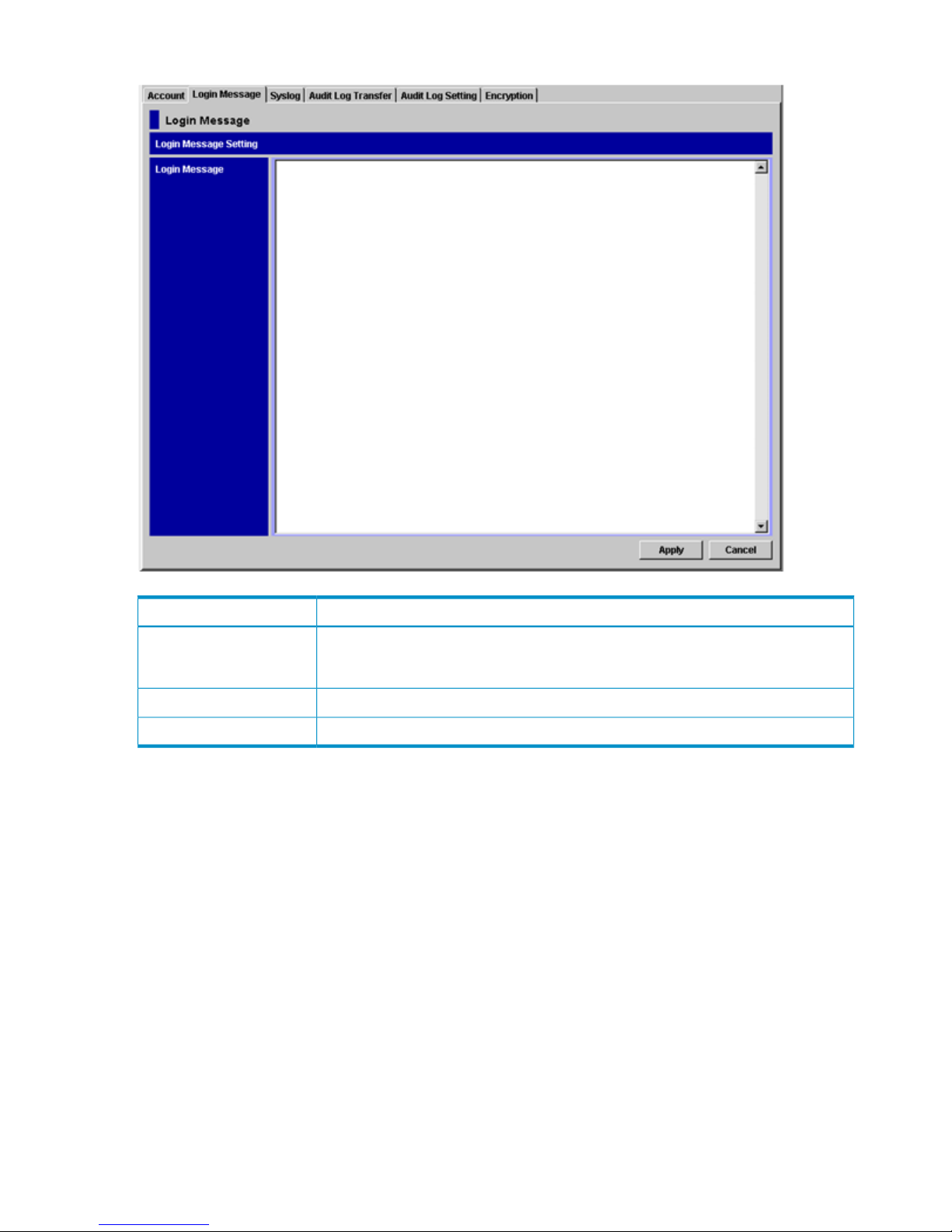
Figure 34 Login Message Window
DescriptionItem
You can enter alphanumeric characters (ASCII codes) and some symbols. You can enter
up to 2,408 letters. The message that you enter in this text box will be displayed in the
Remote Web Console Login window.
Login Message
Implements all the changes or settings. This button is available only in Modify mode.Apply button
Cancels the changes or settings. This button is available only in Modify mode.Cancel button
Syslog Window
The Syslog window allows you to configure syslog servers to transfer the audit log or to download
a syslog file to the Remote Web Console computer immediately when received.
UDP is required for transferring the audit log to the syslog servers. To transfer the audit log to syslog
servers, consider the characteristics of UDP when you design a network. For detailed information
on syslog, see the RFC3164 published by IETF.
Only the storage administrator can configure a syslog server for transferring audit logs or
downloading the syslog file. Before a syslog server can be configured, the Audit Log Administrator
role needs to be set to Modify for that storage administrator's user account. If the Audit Log
Administrator role is set to View, the storage administrator can view the Syslog window and
download the syslog file, but cannot change settings of the Syslog window. For the procedure on
how to change settings in the Syslog window, see the HP StorageWorks XP24000/XP20000 Audit
Log User and Reference Guide.
To open the Syslog window, log in to Remote Web Console, and then select Go, Security and
Syslog from the menu bar of the Remote Web Console main window. A storage partition
administrator cannot display the Syslog window.
72 Using the Remote Web Console GUI
Page 73
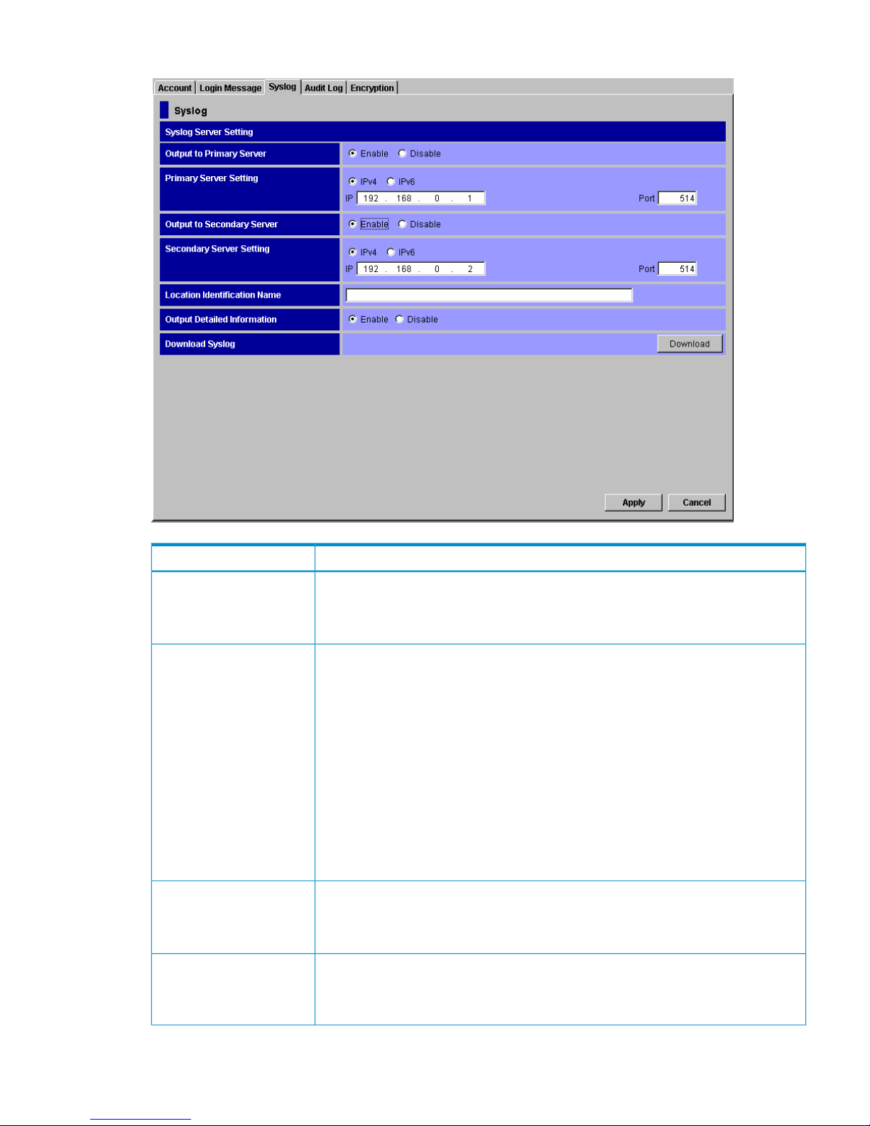
Figure 35 Syslog Window
DescriptionItem
Specify whether to transfer the audit log to the primary syslog server.
• Enable: Transfers the audit log.
• Disable: Does not transfer the audit log.
Output to Primary Server
Set an IP address and a port number for the primary syslog server. Once you set Output
to Primary Server to Enable, IP and Port become available. For both IP and Port, the
defaults have been entered, so change them as needed.
You can set either an IPv4 address or IPv6 address for the IP address. However, only an
IPv4 address is available when the operating system of your SVP is Windows XP.
• To set an IPv4 address, select IPv4. For IP, enter four integers in the range of 0 to
255 (for example, nnn.nnn.nnn.nnn, where n is a number). Only enter numbers.
Do not enter the intervening periods.
• To set an IPv6 address, select IPv6. For IP, enter eight hexadecimal numbers in the
range of 0 to FFFF (for example, hhhh:hhhh:hhhh:hhhh:hhhh:hhhh:hhhh:hhhh,
where h is a hexadecimal digit). Only enter hexadecimal numbers. Do not enter the
intervening colons.
• For Port, enter one integer in the range of 1 to 65,535.
Primary Server Setting
Specify whether to transfer the audit log to the secondary syslog server.
• Enable: Transfers the audit log.
• Disable: Does not transfer the audit log.
Output to Secondary Server
Set an IP address and a port number for the secondary syslog server. Once you set
Output to Secondary Server to Enable, IP and Port become available. For both IP and
Port , the defaults have been entered, so change them as needed. The restriction for the
available values is the same as that of Primary Server Setting.
Secondary Server Setting
Syslog Window 73
Page 74

DescriptionItem
Name, as you like, the storage system that transfers the audit log to syslog servers so
that you can identify the storage system. Enter 32 one-byte characters at the maximum.
Available characters are alphabetic (A-Z and a-z), numeric (0-9), and symbols (! " # $
% & ' ( ) = - ~ ^ | \ { } [ ] @ ` : ; * + _ ? / < > .). However, a comma (,) and a space
cannot be used.
Location Identification Name
Set whether to transfer the detailed information for the audit log file to the syslog server.
To transfer the detailed information to the syslog server, select Enable. If you do not,
select Disable. In the syslog file that is stored in the SVP, the detailed information is always
stored, regardless of this setting.
Output Detailed Information
Downloads the syslog file to the web console client computer.Download Syslog
Implements all the settings. This button is available only in Modify mode.Apply button
Cancels all the settings. This button is available only in Modify mode.Cancel button
Audit Log Transfer Window
A storage administrator uses this window to configure FTP servers and manually transfer the audit
log file to the FTP servers. The Audit Log Administrator role needs to be set to Modify for that storage
administrator's user account. If the Audit Log Administrator role is set to View, the storage
administrator can view the Audit Log Transfer window, but not change settings or manually transfer
the audit log file to the FTP servers.
A SIM occurs to notify a storage administrator of the failure of an FTP transfer. This can occur when
the audit log file is not successfully transferred to any FTP server due to the failures of either the
FTP server or LAN. You can view the SIM in the Alerts window. The reference code for a failed
FTP transfer is 7C0300. If a SIM occurs, do the following:
• Resolve the error condition on the FTP server or LAN, and then manually transfer the audit log
file by clicking Transfer in the Audit Log Transfer window. After that, complete the SIM in the
Audit Log Transfer window.
• If the error condition cannot be resolved, download the audit log file to the Remote Web
Console computer by clicking Audit:Warning or Audit:Wraparound in the Remote Web Console
main window.
To open the Audit Log Transfer window, log in to Remote Web Console, and then select Go,
Security and Audit Log Transfer from the menu bar of the Remote Web Console main window.
Storage partition administrators cannot display the Audit Log Transfer window.
74 Using the Remote Web Console GUI
Page 75
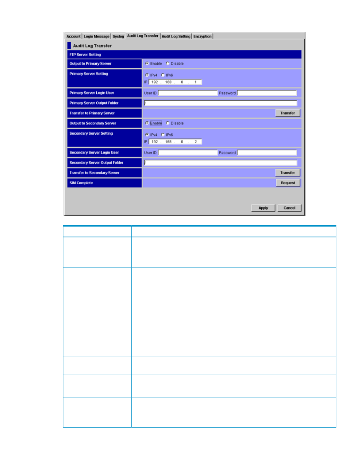
Figure 36 Audit Log Transfer Window
DescriptionItem
Specify whether to transfer the audit log file to the primary FTP server.
• Enable: Transfers the file.
• Disable: Does not transfer the file.
Output to Primary Server
Set an IP address for the primary FTP server. Once you set Output to Primary Server to
Enable, IP becomes available. The default IP address has been entered, so change it as
needed.
You can set either an IPv4 address or an IPv6 address for IP address. However, only an
IPv4 address is available when the operating system of your SVP is Windows XP.
• To set an IPv4 address, select IPv4. For IP, enter four integers in the range of 0 to
255 (for example, nnn.nnn.nnn.nnn, where n is a number). Only enter numbers.
Do not enter the intervening periods.
• To set an IPv6 address, select IPv6. For IP, enter eight hexadecimal numbers in the
range of 0 to FFFF (for example, hhhh:hhhh:hhhh:hhhh:hhhh:hhhh:hhhh:hhhh,
where h is a hexadecimal digit). Only enter hexadecimal numbers. Do not enter the
intervening colons.
Primary Server Setting
Set the UserID and Password to log in to the primary FTP server. Enter up to 256
alphanumeric characters and symbols (ASCII codes) for the user ID and password.
Primary Server Login User
Set the folder location to save the audit log file. The folder location should be relative to
a home directory of an FTP server user. The default setting (/) is the home directory. Enter
up to 256 alphanumeric characters and symbols (ASCII codes) for the output folder.
Primary Server Output
Folder
When you click Transfer, the audit log file is transferred to the primary FTP server
according to the settings selected on the Audit Log Transfer window. You can transfer
the current audit log file without waiting for the audit log file to reach the threshold size
for automatic transfer.
Transfer to Primary Server
Audit Log Transfer Window 75
Page 76

DescriptionItem
Specify whether to transfer the audit log file to the secondary FTP server.
• Enable: Transfers the file.
• Disable: Does not transfer the file.
Output to Secondary Server
Set an IP address for the secondary FTP server. Once you set Output to Secondary Server
to Enable, IP becomes available. The default IP address has been entered, so change it
as needed. The restriction for the available values is the same as that of Primary Server
Setting.
Secondary Server Setting
Set the UserID and Password to log in to the secondary FTP server. The restriction for the
available values is the same as that of Primary Server Login User.
Secondary Server Login User
Set the folder location to save the audit log file. The folder location should be relative to
the home directory of an FTP server user. The default setting and the restriction for the
available values are the same as those of Primary Server Output Folder.
Secondary Server Output
Folder
When you click Transfer, the audit log file is transferred to the secondary FTP server
according to the settings selected on the Audit Log Transfer window. You can transfer
the current audit log file without waiting for the audit log file to reach the threshold size
for automatic transfer.
Transfer to Secondary Server
The Request button allows you to complete (resolve) the SIM that occurs when a transfer
of audit logs to any FTP server fails. Resolve the error condition, manually transfer the
audit log file by clicking Transfer, and then complete the SIM. The SIM status will change
to Complete.
IMPORTANT: If you do not complete the SIM, the SIM will not occur the next time an
FTP transfer fails.
SIM Complete
Implements all the settings. This button is available only in Modify mode.Apply button
Cancels all the settings. This button is available only in Modify mode.Cancel button
Audit Log Setting Window
A storage administrator uses this window to configure the audit log setting. The Audit Log
Administrator role needs to be set to Modify for that storage administrator's user account. If Audit
Log Administrator Role is set to View, the storage administrator can view but not change the audit
log setting.
To open the Audit Log Setting window, log in to Remote Web Console, and then select Go, Security
and Audit Log Setting on the menu bar of the Remote Web Console main window. A storage
partition administrator cannot display the Audit Log Setting window.
76 Using the Remote Web Console GUI
Page 77
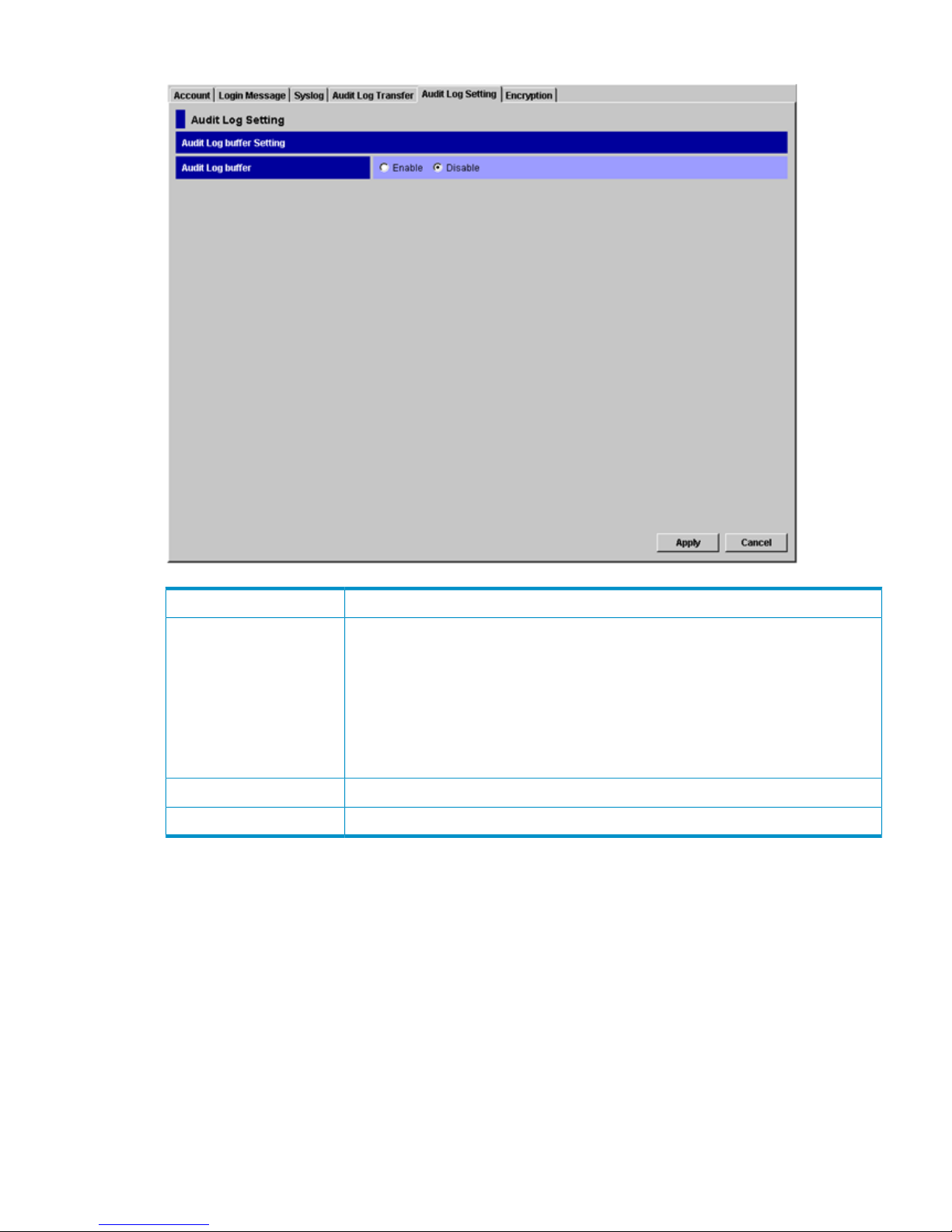
Figure 37 Audit Log Setting Window
DescriptionItem
Specifies whether to temporarily store the audit log on a system disk so the information
will not be lost.
• Enable: Temporarily stores the audit log on a system disk. If you need to keep track
of commands sent from the host, Enable is recommended. If you select Enable, make
sure that a system disk is already created by a storage administrator. For instructions
on how to create a system disk, see the HP StorageWorks XP24000/XP20000 Virtual
LVI/LUN (VLL) and Volume Shredder User Guide.
• Disable: Does not store the log on a system disk.
Audit Log buffer
Implements the setting. This button is available only in Modify mode.Apply button
Cancels the setting. This button is available only in Modify mode.Cancel button
Encryption Window
The Encryption window allows you to back up the encryption key in the Remote Web Console
computer and restore the backed up encryption key. This key is used to encrypt and decrypt data
in the storage system. To back up or restore the key, the Encryption Administrator role must be set
to Enable. For detailed information about the displayed items, see the HP StorageWorks
XP24000/XP20000 Disk Encryption User Guide.
E-mail Information Window
The E-mail Information window allows you to configure settings to automatically send email for
any SIMs caused by software licensing events or XP Thin Provisioning threshold events. You can
also send a test email. These threshold events typically require user action. They are caused either
by reaching the trigger levels configured by the user or by a software license needing user attention.
Encryption Window 77
Page 78
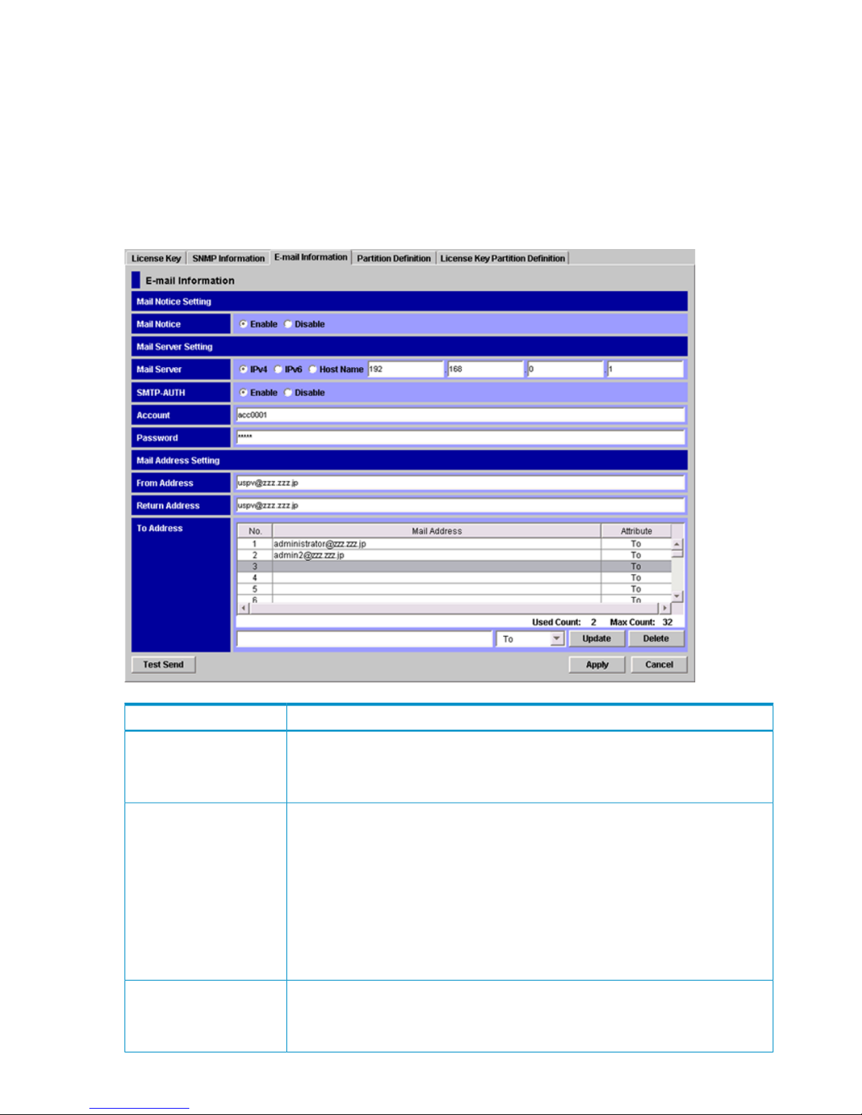
A mail server is required for email notice. The SMTP is used to send emails. You can choose whether
to use SMTP authentication. If a firewall is used, open port 25.
Only the storage administrator can perform operations in the E-mail Information window. The
Storage Administrator role must be set to Enable for that storage administrator's user account, and
also E-mail Information in the Permission Information list must be set to Enable.
To open the E-mail Information window, log in to Remote Web Console, and then select Go,
Environmental Settings and E-mail Information from the menu bar of the Remote Web Console
main window. Storage partition administrators cannot display the E-mail Information window.
Figure 38 E-mail Information Window
DescriptionItem
Specify whether to report SIMs by email.
• Enable: Reports SIMs by email.
• Disable: Does not report SIMs by email.
Mail Notice
Set an IPv4 address, an IPv6 address, or the host name of the mail server.
• To set an IPv4 address, select IPv4 and enter four integers in the range of 0 to 255
(for example, nnn.nnn.nnn.nnn, where n is a number).
• To set an IPv6 address, select IPv6 and enter eight hexadecimal numbers in the range
of 0 to FFFF (for example, hhhh:hhhh:hhhh:hhhh:hhhh:hhhh:hhhh:hhhh,
where h is a hexadecimal digit). Enter 0 to omit a segment.
• To set a host name, select Host Name and enter up to 63 alphanumeric characters
(ASCII codes) and symbols, except for the following symbols and a space:
" \ ; : , * ? < > | / # & + = [ ] ' { } ^
Mail Server
Specify whether to use SMTP authentication.
• Enable: Uses SMTP authentication.
• Disable: Does not use SMTP authentication.
SMTP-AUTH
78 Using the Remote Web Console GUI
Page 79

DescriptionItem
Set the account and password for SMTP authentication. Required when SMTP-AUTH is
Enable. Enter up to 255 alphanumeric characters and symbols (ASCII codes) for the user
ID and password, except for the following symbols and a space:
" \ ; : , * ? < > | / # & + = [ ] ' { } ^
Account and Password
Specify an email address of the sender. Enter up to 255 alphanumeric characters (ASCII
codes) and symbols ( ! # $ % & + - * / ' ^ { } _ . ).
From Address
Specify a Reply-To address for the email. If you specify this address, replies from the
email receivers will be sent to this address. If you omit this address, replies from the email
receivers will be sent to From Address. The available values are the same as those for
From Address.
Return Address
Specify email addresses of the receivers and the attributes (To, Cc, or Bcc). Up to 32
addresses can be specified. The available values are the same as those for From Address.
To Address
When you click Test Send, test emails are sent to the email addresses of the receivers.
This button is available only in Modify mode.
Test Send button
Implements all the settings. This button is available only in Modify mode.Apply button
Cancels all the settings. This button is available only in Modify mode.Cancel button
Configuration File Loader Window
The Configuration File Loader window allows you to export a spreadsheet file with the current
configuration information, and import a file with the new configuration. You can also see the status
and the error information for the imported file before you apply the changes. For the procedure
in the Configuration File Loader window, see “Using Configuration File Loader” (page 111).
To open the Configuration File Loader window, log in to Remote Web Console, and then select
Go, Configuration File Loader and Configuration File Loader from the menu bar of the Remote Web
Console main window. A storage partition administrator cannot display the Configuration File
Loader window.
Configuration File Loader Window 79
Page 80
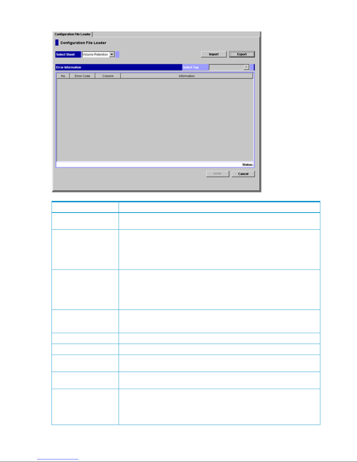
Figure 39 Configuration File Loader Window
DescriptionItem
Select the program product option for which you want to import or export a spreadsheet
file.
Select Sheet
Imports the edited spreadsheet file. For instructions on importing the spreadsheet file,
see “Importing the Spreadsheet” (page 114).
If using the Mozilla web browser, the Download Manager dialog box may display when
you click Import. If this occurs, close the Download Manager dialog box and continue
the operation.
Import button
Exports the current spreadsheet file. For instructions on exporting the spreadsheet file,
see “Exporting a Spreadsheet” (page 112).
If using the Mozilla web browser, the Download Manager dialog box may display when
you click Export. If this occurs, close the Download Manager dialog box and continue
the operation.
Export button
This list is available after you have imported a spreadsheet, and allows you to select the
function tag that you want to display. An asterisk (*) appears after one or more of the
function tags that has an error.
Select Tag
The row number that includes the error.No.
The part code and error number; for example, 8105 (part code) – 1212 (error number).Error Code
The column number that includes the error. A dash (-) indicates that the error column
cannot be specified.
Column
The error message. See the HP StorageWorks XP24000/XP20000 Remote Web Console
Error Codes for the error codes and error messages displayed on the list.
Information
Indicates whether or not there is an error in the imported spreadsheet. If there are no
errors, the Apply button becomes available. The available status conditions are:
• Error
• Ready
Status
80 Using the Remote Web Console GUI
Page 81

DescriptionItem
Implements the settings in the imported spreadsheet. This button becomes available only
when a spreadsheet without detected errors is imported.
Apply button
Cancels the settings and returns you to the original status of the Configuration File Loader
window.
Cancel button
Reports Display Dialog Boxes
The Reports Display dialog box displays the basic configuration information for the storage system.
When you log in as a storage partition administrator, the information on the allocated SLPR is
displayed. The Reports Display dialog box is displayed apart from the Remote Web Console main
window; therefore, it can be displayed regardless of the operation of the Remote Web Console
options. For example, when you perform the setting operation for one of the Remote Web Console
options, you may need to check the existing setting information on the ports or LUNs. In this situation,
you can display the Reports Display dialog box and look at the basic configuration information at
the same time.
To open the Reports Display dialog box, log in to Remote Web Console, and then select File and
Reports from the menu bar of the Remote Web Console main window. For detailed information
about each dialog box, see the subsections in this section.
The information displayed on the Reports Display dialog box is updated:
• When a tab is clicked on the Reports Display dialog box and the displayed dialog box is
changed
• When the Refresh command ( ) is selected on the menu bar of the Remote Web Console
main window
• When a tab is clicked on the Remote Web Console windows during the operation of the
product option and the displayed dialog box is changed
• When the Apply button is clicked on the Remote Web Console main window
• When the operation mode is changed from View mode to Modify mode on the Remote Web
Console main window
Common Elements
The Reports Display dialog box displays the following items:
• The title bar displays information about the connected storage system.
IP indicates the IP address of the SVP.◦
◦ S/N indicates the serial number.
◦ D/N indicates the device name specified in the Identity window.
• If the volume is a LUSE volume, the detailed information for the LUSE volume is available.
Select a LUSE volume in the list on the LUN dialog box or the LDEV dialog box, right-click,
and select the Detail Information command. The detailed information for the LUSE volume is
displayed. For a description of the displayed information, see “Detail Information Dialog Box”
(page 90).
Reports Display Dialog Boxes 81
Page 82
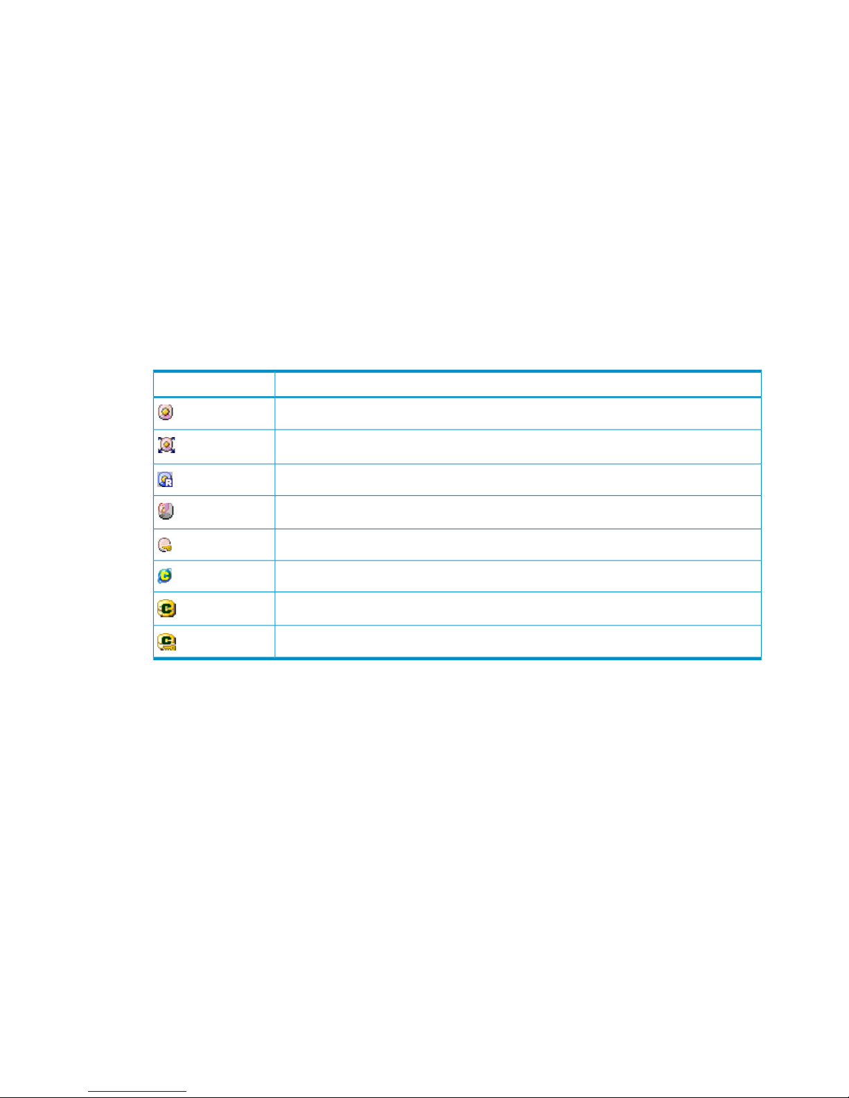
• The LDKC:CU:LDEV column displays the LDKC number, the CU number, and the LDEV number.
These numbers are separated by colons (:).
◦ An LDEV number ending in the pound or gate symbol (#) (for example, 00:00:01 #)
indicates that the LDEV is an external volume. For details regarding external volumes, see
the HP StorageWorks XP24000 External Storage Software User Guide.
◦ An LDEV number ending in V (for example, 00:00:01 V) indicates that the LDEV is an XP
Snapshot virtual volume . For details regarding virtual volumes, see the HP StorageWorks
XP24000/XP20000 Snapshot User Guide.
◦ An LDEV number ending in X (for example, 00:00:01 X) indicates that the LDEV is an XP
Thin Provisioning virtual volume. For details regarding virtual volumes, see the HP
StorageWorks XP24000/XP20000 Thin Provisioning Software User Guide.
◦ An LDEV number ending in M (for example, 00:00:01 M) indicates that the LDEV is a
migration volume.
The icons in the LDKC:CU:LDEV column have the following meaning:
Table 28 Icons in the LDKC:CU:LDEV Column
DescriptionIcons
Normal LDEV
Expanded (LUSE) volume
Reserved volume of XP Auto LUN
Variable-sized volume (CV)
Secured LDEV
Remote command device
Command device
Command device to which the command device security is applied
• You can export the information displayed on the Reports Display dialog box as a CSV file
using the Export button in the lower left of the Reports Display dialog box.
To export the information displayed on the Reports Display dialog box as a CSV file:
1. Click Export in the lower left of the Reports Display dialog box. A dialog box for selecting
the file is displayed.
2. Specify the file name and location to save the file.
3. Click Save. When the save processing finishes, the procedure is complete.
4. Click Close in the lower right of the Reports Display dialog box.
Port Dialog Box
The Port dialog box provides information on ports. The displayed information can be switched
using the SLPR or Type list. Figure 40 (page 83) is an example of the Port dialog box when Fibre
is selected from the Type list.
82 Using the Remote Web Console GUI
Page 83
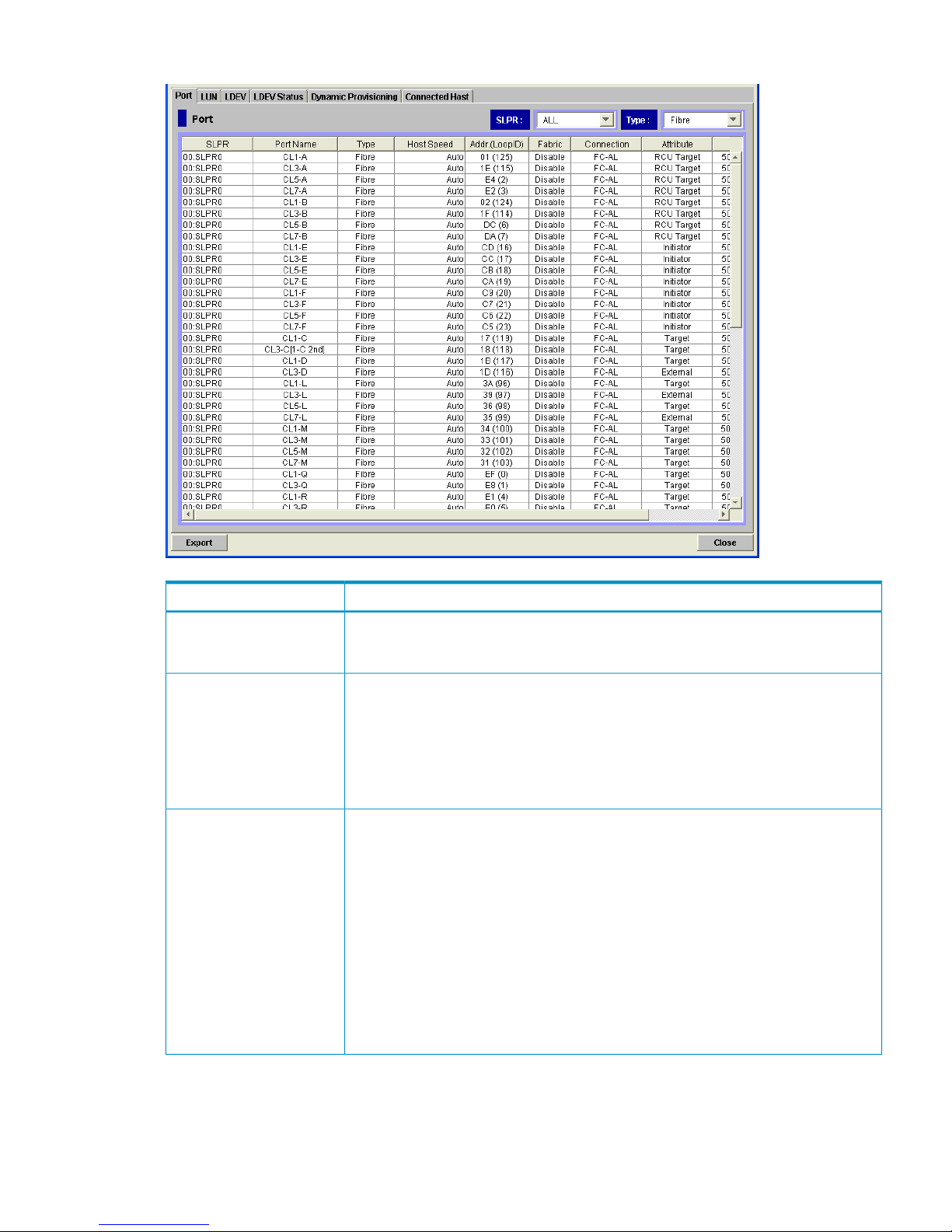
Figure 40 Port Dialog Box (Reports Display, when Fibre Is Selected)
DescriptionItem
Allows you to display the information on a particular SLPR when you select the SLPR from
this list. If you have logged in as a storage partition administrator, only information about
the allocated SLPR is displayed, and you cannot select other SLPRs in this list.
SLPR
Select a port type to view the port information on the Port list. For more detailed
information about the displayed items on the Port list, see the HP StorageWorks
XP24000/XP20000 LUN Manager User Guide.
• Fibre: Information about only the fibre ports is displayed.
• Serial: Information about only the serial ports is displayed.
• Mfibre: Information about only the Mfibre ports is displayed.
Type
Displays the following when Fibre is selected in Type:
• SLPR: SLPR number and SLPR name.
• Port Name: Port name.
• Type: Type of port (Fibre).
• Host Speed: Data transfer speed, in Gbps, for Fibre Channel ports.
• Addr. (Loop ID): Address and Loop ID of the port.
• Fabric: Indicates whether a Fabric switch is used. Enable or Disable is displayed.
• Connection: Topology. FC-AL or P-to-P is displayed.
• Attribute: Port attribute. Initiator, Target, RCU Target, or External is displayed.
• WWN: WWN of the DKC port.
Port list (when Fibre is
selected)
Reports Display Dialog Boxes 83
Page 84
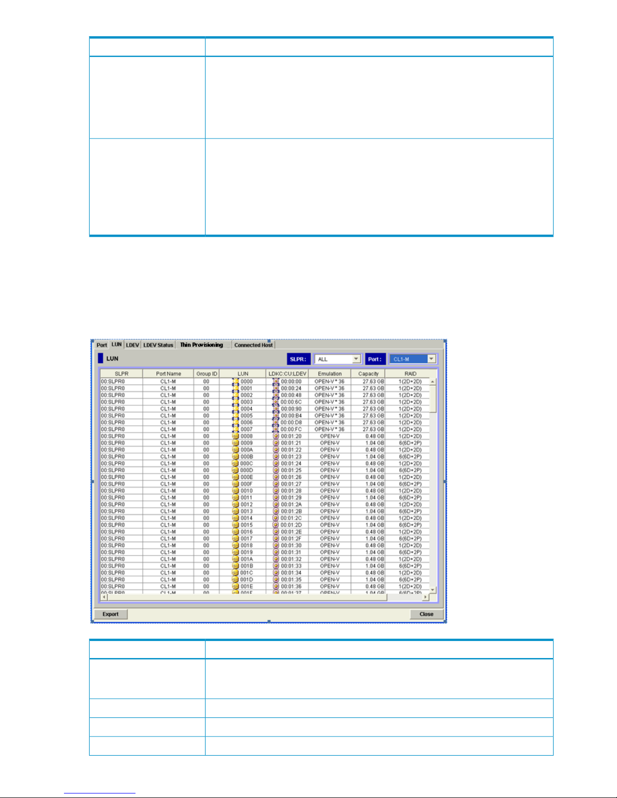
DescriptionItem
Displays the following when Serial is selected in Type:
• SLPR: SLPR number and SLPR name.
• Port Name: Port name.
• Type: Type of port (Serial).
• Attribute: Port attribute. LCP is displayed.
Port list (when Serial is
selected)
Displays the following when Mfibre is selected in Type:
• SLPR: SLPR number and SLPR name.
• Port Name: Port name.
• Type: Type of port (Mfibre).
• Attribute: Port attribute. HTP or FNP is displayed.
• WWN: WWN of the Mfibre port.
Port list (when Mfibre is
selected)
LUN Dialog Box
The LUN dialog box displays information about open-system volumes. For more detailed information
about the displayed items, see the HP StorageWorks XP24000/XP20000 LUN Manager User
Guide.
Figure 41 LUN Dialog Box (Reports Display)
DescriptionItem
Allows you to display information about a particular SLPR when you select the SLPR from
this list. If you have logged in as a storage partition administrator, only information about
the allocated SLPR is displayed, and you cannot select other SLPRs from this list.
SLPR list
Select the port for which information is to be displayed from the list.Port
SLPR number and SLPR name.SLPR column
Port name.Port Name
84 Using the Remote Web Console GUI
Page 85

DescriptionItem
The group number of the host group.Group ID
LUNs (logical unit numbers) assigned to logical volumes.
• : A logical volume to which an LU path is defined
• : An expanded LU
• : A remote command device
• : A command device
• : Command device security
LUN
From the left, the LDKC number, the CU number, and the LDEV number are displayed.
For detailed information, see “Common Elements” (page 81).
LDKC:CU:LDEV
Emulation type.
• For an expanded (LUSE) volume, the number of the LDEVs consisting of the LUSE
volume is displayed after the emulation type (for example, OPEN-V * 3).
• For a TP-VOL, (0V) might be displayed after the emulation type (for example, OPEN-V
(0V)).
Emulation
Volume capacity. For an expanded (LUSE) volume, the total capacity of the LDEVs
consisting of the LUSE volume is displayed.
Capacity
RAID level.RAID
Number of LU paths.Paths
LDEV Dialog Box
The LDEV dialog box provides information about volumes. For more detailed information about
the displayed items, see the HP StorageWorks XP24000/XP20000 Virtual LVI/LUN (VLL) and
Volume Shredder User Guide.
Reports Display Dialog Boxes 85
Page 86
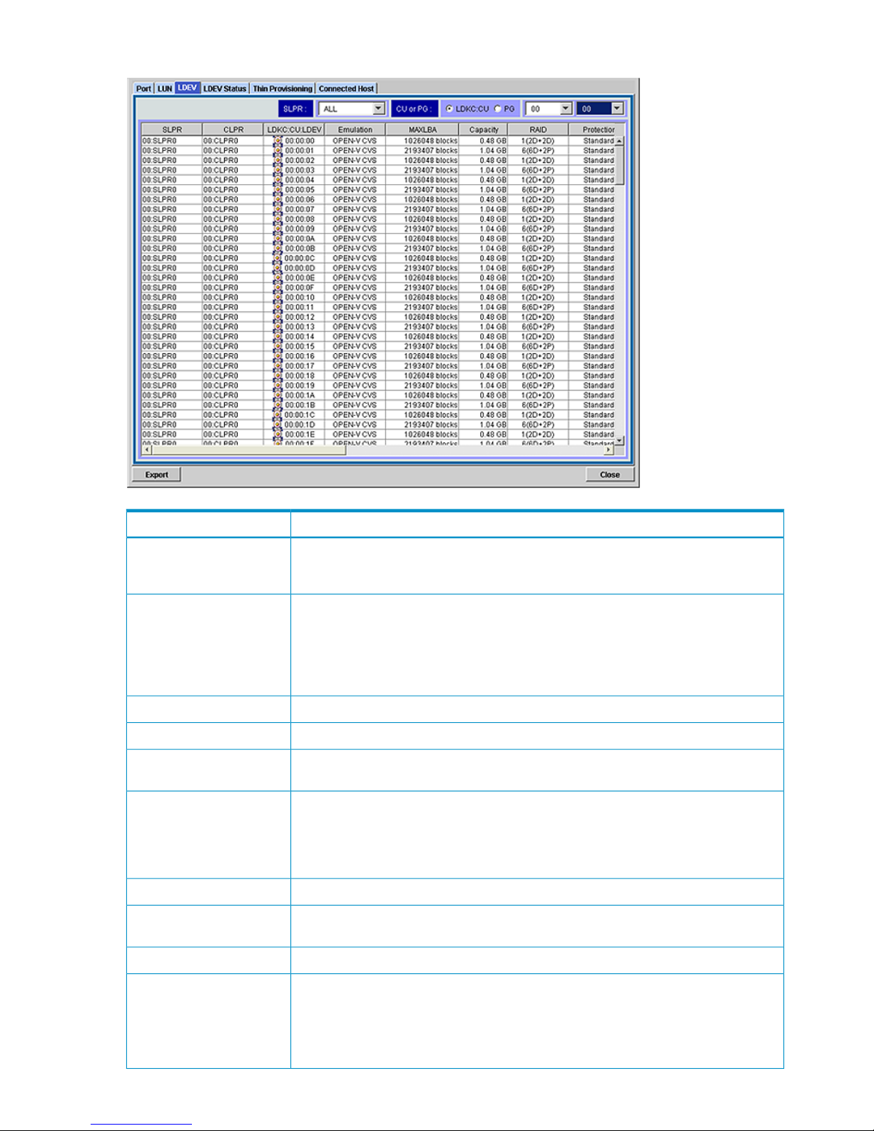
Figure 42 LDEV Dialog Box (Reports Display)
DescriptionItem
Allows you to display information about a particular SLPR when you select the SLPR from
this list. If you have logged in as a storage partition administrator, only information about
the allocated SLPR is displayed, and you cannot select other SLPRs from this list.
SLPR list
Choose which information to display in the LDEV list.
• If you select CU, two lists are displayed. You can select an LDKC from the list on the
left, and a CU from the list on the right.
• If you select PG, one list is displayed. You can select the parity group to display from
the list.
CU or PG
SLPR number and SLPR name.SLPR column
CLPR number and CLPR name.CLPR
The LDKC number, the CU number, and the LDEV number. For detailed information, see
“Common Elements” (page 81).
LDKC:CU:LDEV
Emulation type.
• For an expanded (LUSE) volume, the emulation type of each LDEV is displayed.
• For a TP-VOL, (0V) might be displayed after the emulation type (for example, OPEN-V
(0V)).
Emulation
LDEV size recognized by a host.MAX LBA
Volume capacity. Open-system volumes are displayed in GB, mainframe volumes are
displayed in Cyl. For an expanded (LUSE) volume, the capacity of each LDEV is displayed.
Capacity
RAID level.RAID
Data protection level.
• SATA-W/V: Write & Verify method on SATA drives.
• SATA-E: Enhancing method on SATA drives.
• Standard: Fibre Channel drives, flash drives, external volumes, or V-VOLs.
Protection
86 Using the Remote Web Console GUI
Page 87

DescriptionItem
The hard disk type of internal volume as follows:
• Blank indicates a Fibre Channel drive.
• An asterisk (*) indicates a SATA drive.
• A dollar sign ($) indicates a flash drive.
• A hyphen (-) indicates an external volume.
Internal Volume Information
Indicates if the volume is encrypted or not.
• Enable: The volume is encrypted.
• Disable: The volume is not encrypted.
• A hyphen (-) appears when the volume is not an internal volume.
Encryption
Parity group.Parity Group
Number of LU paths.Paths
The attribute set for the volume as follows:
• Pool (X): The volume is set as a pool-VOL, where X indicates the pool ID.
• V-VOL: The volume is set as a V-VOL for XP Snapshot.
• TP-VOL: The volume is set as a V-VOL for XP Thin Provisioning.
• Reserved LDEV: The volume is set as a reserved volume of XP Auto LUN.
• JNL Volume: The volume is set as a journal volume.
• System Disk: The volume is set as a system disk.
• Quorum Disk: The volume is set as a quorum disk.
Attribute
Information about the external volume is displayed in the format Vendor/ Product name/
Serial number/ Hard disk type. For an internal volume, -/-/-/- is displayed. For a
migration volume, -/-/-/ is displayed. The hard disk type is displayed as follows:
• Blank indicates a Fibre Channel drive.
• An asterisk (*) indicates a BD or SATA drive.
• A dollar sign ($) indicates a flash drive.
• A hyphen (-) indicates an internal volume.
External Volume Information
Number of LU paths that are set for the external volume.External Paths
Cache Mode was set for the external volume when it was mapped. For an internal volume
or a migration volume, a hyphen (-) appears.
Cache Mode
LDEV Status Dialog Box
The LDEV Status dialog box provides information about the status of volumes. For more detailed
information about the displayed items, see the HP StorageWorks XP24000/XP20000 Virtual
LVI/LUN (VLL) and Volume Shredder User Guide.
Reports Display Dialog Boxes 87
Page 88
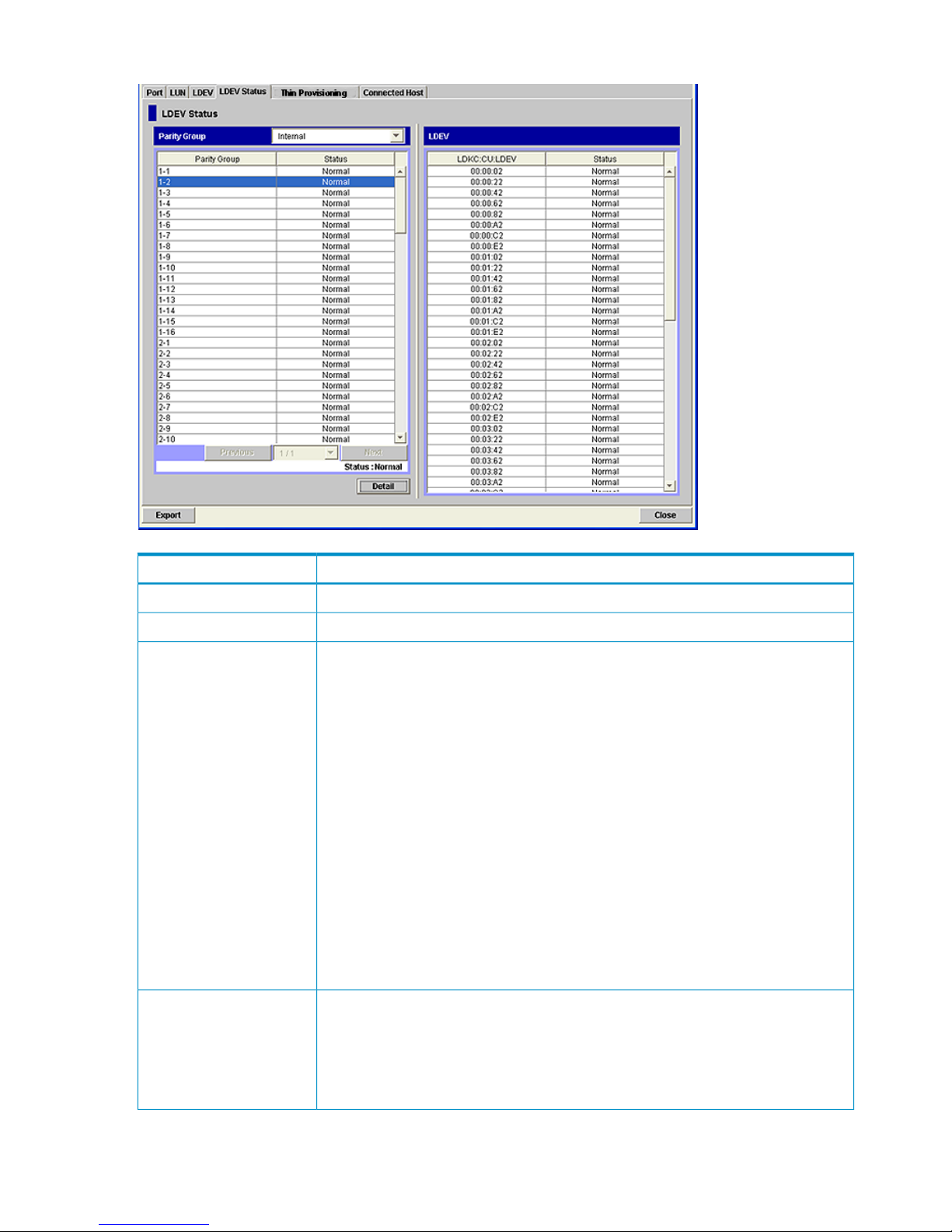
Figure 43 LDEV Status Dialog Box (Reports Display)
DescriptionIdea
Allows you to select which disk group to display.Parity Group list
A parity group number belonging to the selected disk group.Parity Group
A status of all the volumes in the parity group.
• Normal: All the volumes are in a normal status.
• Blocked: All the volumes are in a blocked status.
• Format: All the volumes are being formatted.
• Preparing Quick Format: All the volumes are being prepared for Quick Format.
• Normal (Quick Format): Quick Format is in progress. When a parity group contains
both the Normal and Normal (Quick Format) statuses, the list also displays Normal
(Quick Format).
• Correction Access: The access attributes of all the volumes are being changed.
• Copying: Data in all the volumes is being copied.
• Read Only: Hosts can only read the volumes.
• Shredding: The shredding operation is in progress.
• Unknown: The system does not recognize the status of any volumes.
• Warning: Some volumes are not in a normal status.
• —: The statuses of the volumes are none of the above.
Status
Displays up to 4,096 parity groups per page. When more parity groups are defined,
use the following functions to see the entire list:
• List: Displays the current page number. It also allows you to display the desired page.
• Previous: Displays the previous page.
• Next: Displays the next page.
Page switching area
88 Using the Remote Web Console GUI
Page 89

DescriptionIdea
Displays the status of the disk group that you have selected in the Parity Group list.
• Normal: All the volumes are in a normal status.
• Warning: Not all the volumes are in a normal status.
Status area
When you select a parity group in the list and click Detail, all the LDEVs in the parity
group are displayed in the LDEV list on the right.
Detail button
From the left, the LDKC number, the CU number, and the LDEV number are displayed.
For detailed information, see “Common Elements” (page 81).
LDKC:CU:LDEV
The status of a volume.
• Normal: The volume is in a normal status.
• Blocked: The volume is in a blocked status.
• Format: The volume is being formatted.
• Preparing Quick Format: The volume is being prepared for Quick Format.
• Normal (Quick Format): Quick Format is in progress.
• Correction Access: The access attribute of the volume is being changed.
• Copying: Data in the volume is being copied.
• Read Only: Hosts can only read the volume.
• Shredding: The shredding operation is in progress.
• Unknown: The system does not recognize the status of the volume.
Status
XP Thin Provisioning Dialog Box
The XP Thin Provisioning dialog box provides information about XP Thin Provisioning volumes. For
detailed information about the displayed items, see the HP StorageWorks XP24000/XP20000
Thin Provisioning Software User Guide.
Connected Host Dialog Box
The Connected Host dialog box provides information about mainframe hosts.
Reports Display Dialog Boxes 89
Page 90
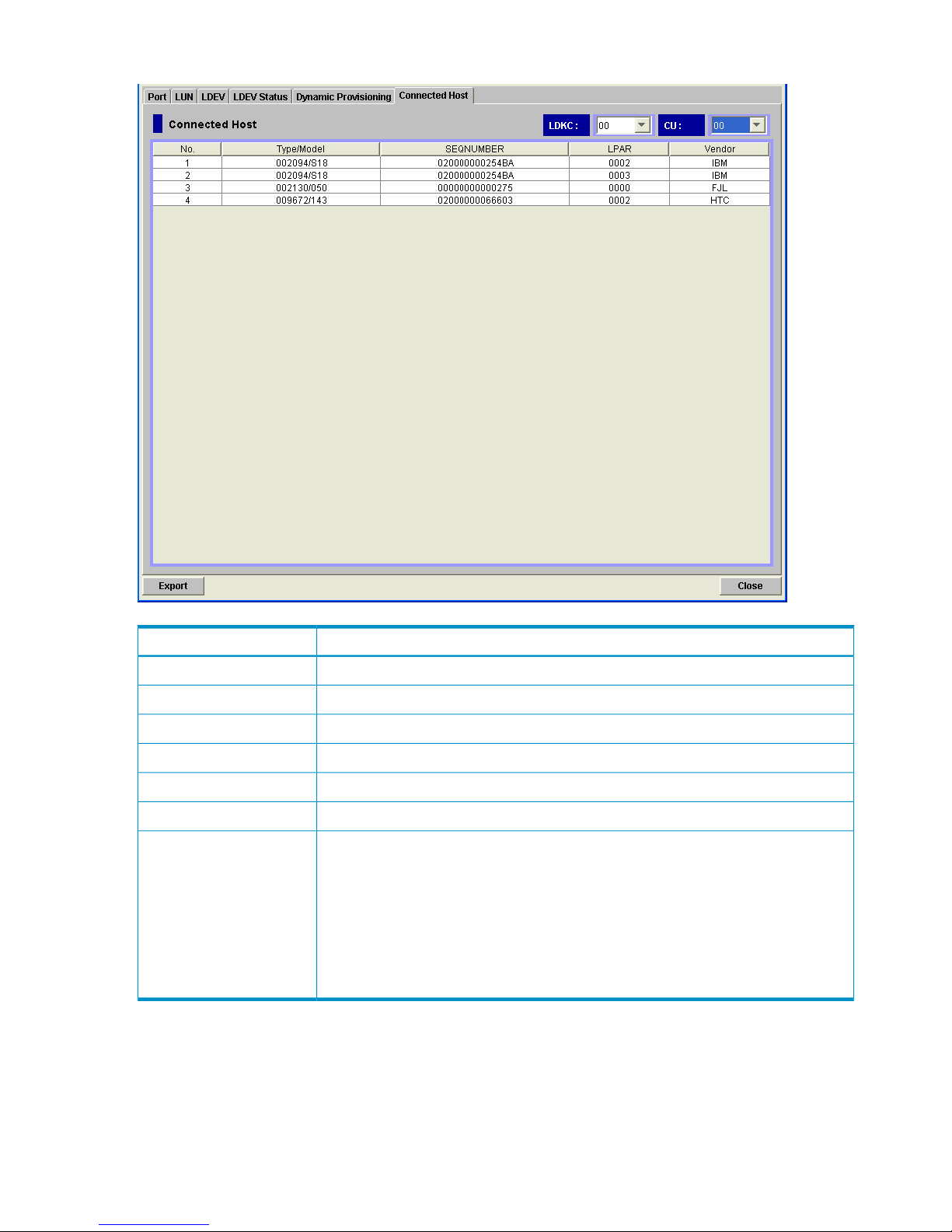
Figure 44 Connected Host Dialog Box (Reports Display)
DescriptionItem
Allows you to select the LDKC for which information is to be displayed.LDKC
Allows you to select the CU for which information is to be displayed.CU
The sequential number of the list.No.
The type and model number of a host (or a channel extender).Type/Model
The node ID of a host (or a channel extender).SEQNUMBER
The logical partition number of a host.LPAR
The vendor of the host.
• FJT (Fujitsu)
• IBM
• HTC (HP)
• CNT(Ex)
If CNT(Ex) appears, the table row indicates the type, model number, and node ID of a
channel extender.
Vendor
Detail Information Dialog Box
The Detail Information dialog box provides information about the LUSE volume selected in the LUN
dialog box (see “LUN Dialog Box (Reports Display)” (page 84)) or the LDEV dialog box (see “LDEV
Dialog Box (Reports Display)” (page 86)). Right-click the LUSE volume and select Detail Information
to view the detailed information about the LUSE volume on the Detail Information dialog box.
90 Using the Remote Web Console GUI
Page 91
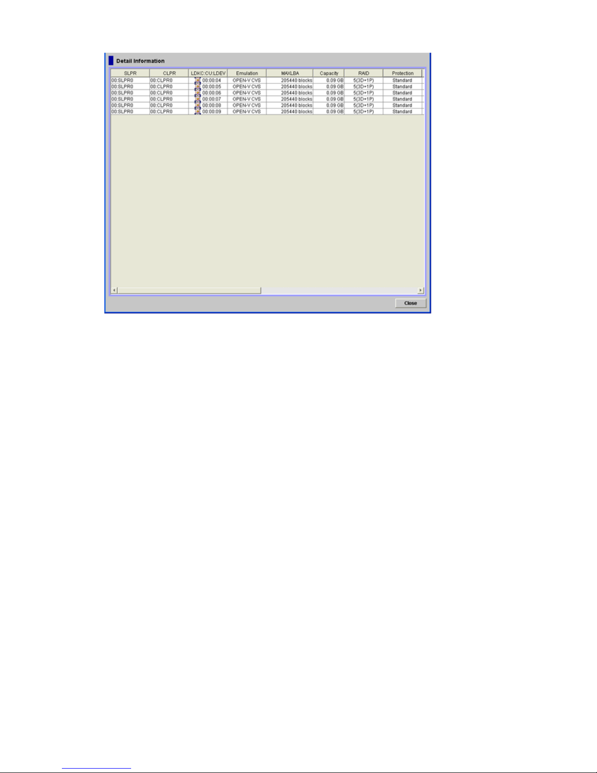
Figure 45 Detail Information Dialog Box (Reports Display)
The Detail Information dialog box displays the same items as the LDEV list in the LDEV dialog box
on the Reports Display dialog box (see “LDEV Dialog Box” (page 85)).
Tool Panel
The Tool Panel allows you to specify the environment parameters of Remote Web Console or
configure SSL-encrypted communications. HP recommends that you add the Tool Panel to your
favorites on your web browser.
To open the Tool Panel, access the following URL on the web browser of the Remote Web Console
computer:
http://xxx.xxx.xxx.xxx/cgi-bin/utility/toolpanel.cgi
xxx.xxx.xxx.xxx is the IP address or the host name of the SVP.
Tool Panel 91
Page 92
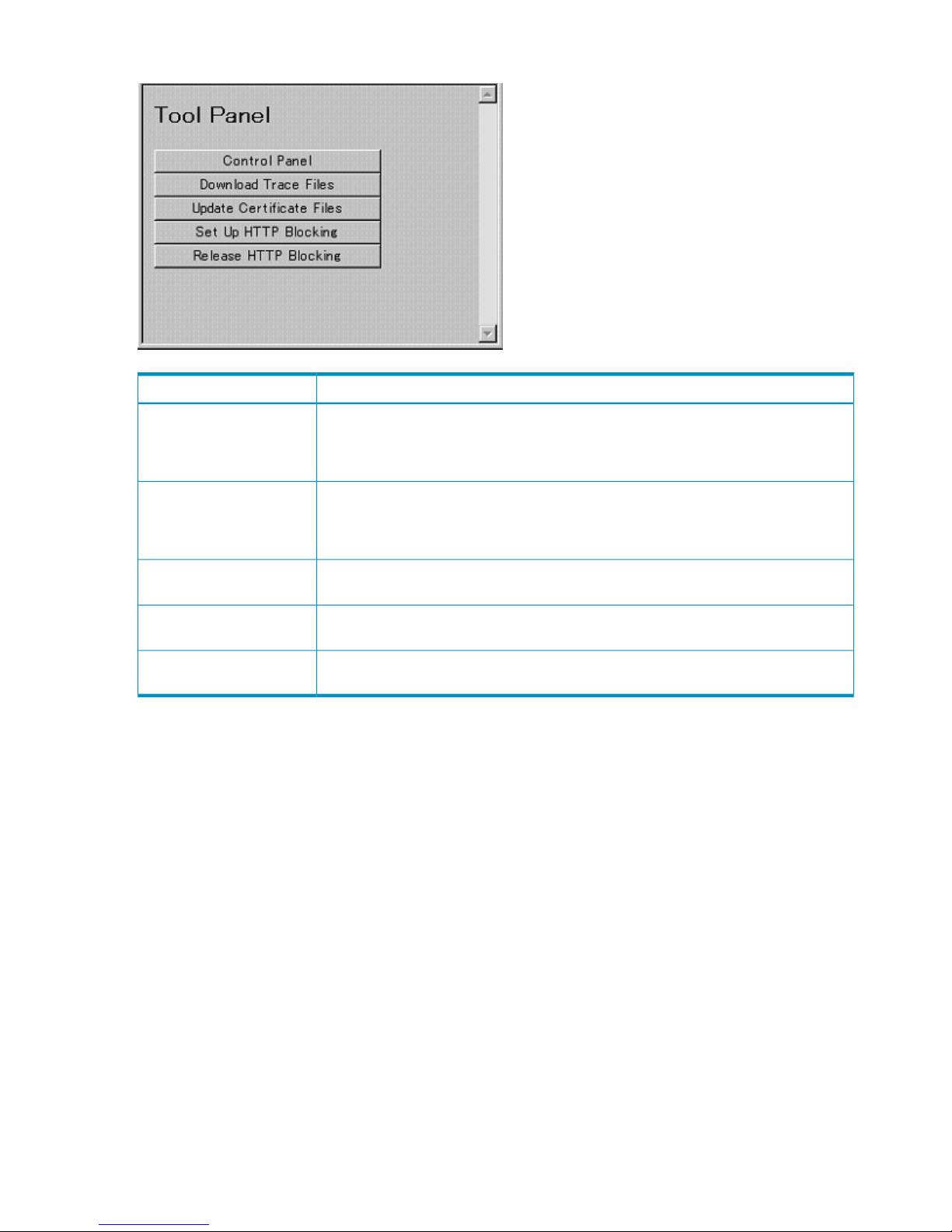
Figure 46 Tool Panel
DescriptionItem
Opens the Remote Web Console Control Panel, where the storage administrator can set
Remote Web Console environment parameters, download files of configuration
information, and restore the downloaded backup files of the Remote Web Console
configuration information. For more information, see “Control Panel” (page 92).
Control Panel
Opens the FD Dump Tool, where the storage administrator can download the Remote
Web Console configuration information from the SVP either onto a floppy disk or onto
a hard disk drive. For more information, see “Downloading Trace Files Using the FD
Dump Tool” (page 110).
Download Trace Files
Allows you to load certificate files to set up SSL-encrypted communications for Remote
Web Console. For more information, contact your HP service representative.
Update Certificate Files
Allows you to set up HTTP communications blocking between Remote Web Console and
the web server. For more information, contact your HP service representative.
Set Up HTTP Blocking
Allows you to release HTTP communications blocking. For more information, contact your
HP service representative.
Release HTTP Blocking
Control Panel
From the Remote Web Console Control Panel, the storage administrator can set Remote Web
Console environment parameters, download files of configuration information, and restore the
downloaded backup files of the Remote Web Console configuration information.
To open the Remote Web Console Control Panel, click Control Panel in the Tool Panel dialog box
(see “Tool Panel” (page 91)) and log in from the displayed dialog box. Only storage administrators
can open the Control Panel.
Set Env. Dialog Box
The Set Env. dialog box allows a storage administrator to set the Remote Web Console environment
parameters. For detailed operation privileges required for the Set Env. dialog box or detailed
operations on the Set Env. dialog box, see “Setting the Environment Parameters” (page 106).
To open the Set Env. dialog box, click the Set Env. tab in the Control Panel.
92 Using the Remote Web Console GUI
Page 93
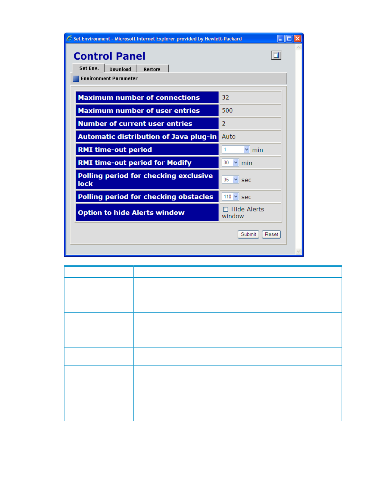
Figure 47 Set Env. Dialog Box (Control Panel)
DescriptionItem
The maximum number of Remote Web Console users who can concurrently connect to
the same storage system.
You cannot change this value from Remote Web Console. Contact your HP service
representative to change the default setting.
Maximum number of
connections
The maximum number of user entries that can be registered in the user account list of a
storage system.
You cannot change this value from Remote Web Console. Contact your HP service
representative to change the default setting.
Maximum number of user
entries
The number of user accounts currently registered in the user account list.Number of current user
entries
The JRE is required to use Remote Web Console, but if a Remote Web Console computer
(Java client) does not have the JRE, the following will be executed when the user logs in
to the SVP:
• For Windows: The SVP automatically distributes and installs the appropriate JRE onto
that Remote Web Console computer.
• For UNIX: The SVP automatically opens the appropriate web page to download the
JRE onto that Remote Web Console computer.
Automatic distribution of
Java plug-in
Control Panel 93
Page 94

DescriptionItem
If the user cannot access the SVP for a certain period of time because of a network error,
the RMI time-out logs the user out of the SVP. This has the following parameters:
• The default is 1 minute. You can specify 1 minute, 5 - 60 minutes in 5-minute
increments, 70 to 120 minutes in 10-minute increments, or One day (24 hours).
• The value of the RMI time-out period must be greater than the value set for the smallest
polling period, either for checking exclusive lock or for checking obstacles (see the
following for those parameters). For example, specify a value of the RMI time-out
period to satisfy the following condition:
RMI time-out period > min [A, B]
where
A = Polling period for checking exclusive lock
B = Polling period for checking obstacles, and min [A, B] indicates
the minimum value selected from A and B.
You cannot disable this parameter.
RMI time-out period
If a user is in Modify mode but does not make any changes that access the RMI server
for a specified period of time, Modify mode is released, and View mode appears.
• The default time period is 30 minutes. You can specify between 10 and 60 minutes
in 10-minute increments, or between 120 and 360 minutes in 60-minute increments.
• Specify NO to disable this parameter.
RMI time-out period for
Modify
Specify the polling period for monitoring who is changing information while in Modify
mode when other users are viewing the storage system information in View mode. The
Locked and Unlocked icons are automatically updated either when a user who is in
Modify mode logs out of Remote Web Console or changes to View mode (see “Icons”
(page 55)).
• The default time period is 35 seconds. You can specify 5 to 60 in 5-second increments,
or 70 to 120 in 10-second increments. The shorter the time period you specify, the
more frequently the Lock/Unlock status is updated, but this does increase network
traffic.
• Specify NO to disable this parameter.
Polling period for checking
exclusive lock
Specify a time interval to monitor the Disk Controller and Disk Array Unit status, which
is displayed by the status lamp icon on the Alerts window of the Remote Web Console
main window.
• The default time period is 110 seconds. You can specify 5 to 60 seconds in 5-second
increments, and 70 to 120 seconds in 10-second increments for the parameter.
• Specify NO to disable this parameter. HP recommends that you select NO when the
Option to hide Alerts window check box is selected.
Polling period for checking
obstacles
Specify whether to display the Alerts window (see “Alerts Window” (page 68)). If the
Hide Alerts window check box is selected, the Status tab does not appear in the Remote
Web Console main window. By default, the check box is cleared. HP recommends that
you select NO for Polling period for checking obstacles when the Option to hide Alerts
window check box is selected.
Option to hide Alerts
window
Submits the settings that you have made. You need to log out of Remote Web Console
once and log in again for the new settings to take effect.
Submit button
Resets the Remote Web Console settings to the defaults.Reset button
Download Dialog Box
The Download dialog box allows a storage administrator to download files containing the Remote
Web Console configuration information. To open the Download dialog box, click the Download
tab in the Control Panel.
94 Using the Remote Web Console GUI
Page 95
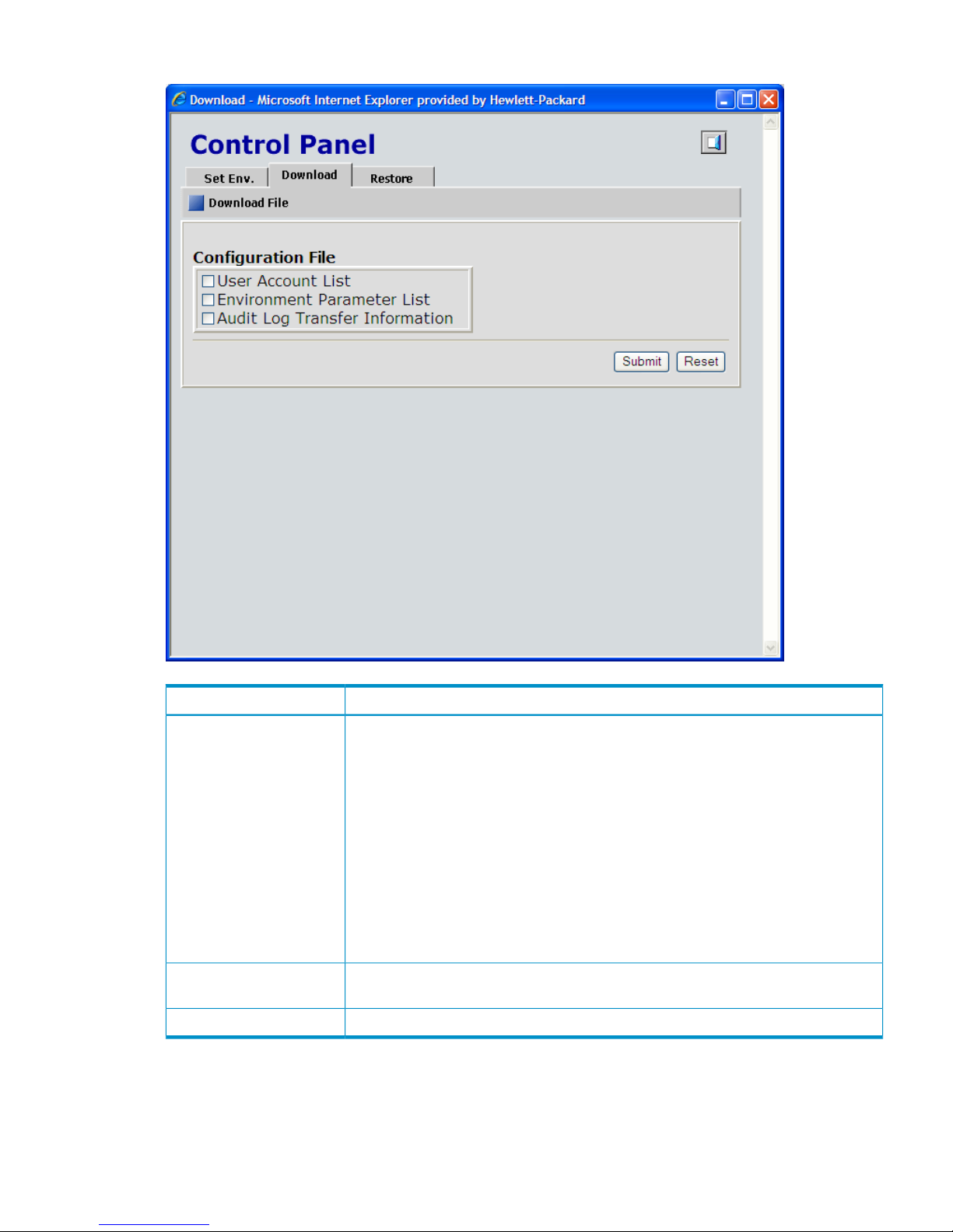
Figure 48 Download Dialog Box (Control Panel)
DescriptionItem
The check boxes indicate the configuration files that can be downloaded. Select a check
box and click Submit to download the file containing the information. The files that you
can download depend on the operation privileges set for your user account. The files
and privileges required to download are as follows:
• User Account List: A storage administrator with the Account Administrator role set to
Modify or View can download the file containing the list of user accounts (settings on
the Account window).
• Environment Parameter List: A storage administrator with the Storage Administrator
role set to Enable can download the file containing the Remote Web Console
environment parameters (settings on the Set Env. dialog box).
• Audit Log Transfer Information: A storage administrator with the Audit Log
Administrator role set to Modify or View can download the file containing the settings
of the Syslog window and the Audit Log Transfer window.
Configuration File
Opens the Download File dialog box (see “Download File Dialog Box after the Files Are
Selected” (page 107)) to download the selected files.
Submit button
Clears all the check boxes.Reset button
Restore Dialog Box
The Restore dialog box allows a storage administrator to restore configuration files that were
previously backed up. To open the Restore dialog box, click the Restore tab in the Control Panel.
Control Panel 95
Page 96
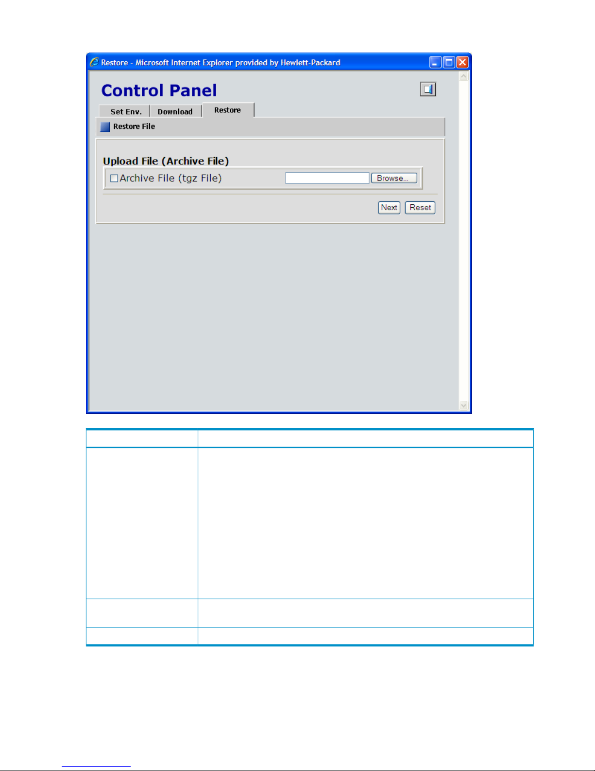
Figure 49 Restore Dialog Box (Control Panel)
DescriptionItem
Select the Archive File (tgz File) check box and specify the compressed file (backup file),
which has previously been downloaded from the Download dialog box in the Control
Panel. The file extension must be tgz. To specify the directory of the backup file, click
Browse and then select the location.
The files that you can restore depend on the operation privileges set for your user account,
even if you specify a compressed file that contains all configuration files. The files and
privileges required to restore are as follows:
• To restore the user account list, the Account Administrator role must be set to Modify.
• To restore the environment parameters, the Storage Administrator role must be set to
Enable.
• To restore the audit log and syslog settings, the Audit Log Administrator role must be
set to Modify.
Upload File (Archive File)
Takes you to the next step of restoring backup files, where you will specify the restoring
file in Upload File, and then you can click Next.
Next button
Clears all the check boxes and text boxes.Reset button
96 Using the Remote Web Console GUI
Page 97

4 Performing Remote Web Console Operations
This chapter describes how to perform Remote Web Console operations:
• “Enabling and Disabling Remote Web Console Options” (page 97)
• “Launching the Desired Option” (page 100)
• “Managing the User Accounts” (page 101)
• “Reporting SIMs by Email” (page 104)
• “Setting the Environment Parameters” (page 106)
• “Downloading the Configuration Files” (page 106)
• “Restoring Backups of the Configuration Files” (page 107)
• “Downloading Trace Files Using the FD Dump Tool” (page 110)
• “Using Configuration File Loader” (page 111)
• “Registering and Deleting the Certificates of HP Systems Insight Manager” (page 115)
Enabling and Disabling Remote Web Console Options
To activate the program product options for the storage system on Remote Web Console, the
program product options need to be installed using license keys. This section describes the program
product options on Remote Web Console, and the procedures for installing and uninstalling the
program product options from the License Key window (see “License Key Window” (page 56)).
Only storage administrators can install and uninstall the program product options.
If storage partition administrators want to use the program product options for their own SLPRs,
storage administrators have to install the program product options using the License Key window,
and then allocate the licensed capacity for each program product option to SLPRs using the License
Key Partition Definition window. For a description of the License Key Partition Definition window
and the procedure for allocating licensed capacity to the SLPRs, see the HP StorageWorks
XP24000/XP20000 Disk/Cache Partition User Guide.
Enabling Options Using a License Key Code
To enable a Remote Web Console option by using the license key code:
1. Log in to Remote Web Console and open the License Key window (see “License Key Window”
(page 56)).
2. Change to Modify mode (see “Changing Between View Mode and Modify Mode” (page 41)
if you need instructions).
3. Select Key Code in Mode.
4. In Key Code, enter the license key code. You cannot copy and paste text from other
applications.
5. Click Install.
The row of the installed option changes to blue bold italics, and the Status column changes
to Install.
• Important: To implement the setting, you must click Apply.
• To disable the term key, perform the operations described in “Enabling or Disabling a
License” (page 99).
• When you want to enable other options, repeat steps 3 through 5.
Enabling and Disabling Remote Web Console Options 97
Page 98

6. Click Apply (or Cancel). The status of the enabled options changes to Installed. The warning
messages are displayed in the following cases:
• The error code # 405 5503 is displayed if you install an emergency key for an option
that has already been installed with a permanent key.
If you install the emergency key, it expires in 30 days.
• The error code #405 5501 is displayed if you install an emergency key when the option
has already been installed with a temporary key, and the remaining lifetime of the option
is more than 30 days.
You cannot install an emergency key under these circumstances.
For details on these error codes, see the HP StorageWorks XP24000/XP20000 Remote Web
Console Error Codes.
Enabling Options Using a License Key File
You can enable multiple options in a single procedure using a license key file. The license key files
are provided by HP.
To install Remote Web Console options on Remote Web Console using the license key file:
1. Log in to Remote Web Console and open the License Key window (see “License Key Window”
(page 56)).
2. Change to Modify mode.
3. From Mode, click File.
The Browse button becomes available.
4. Click Browse to display the dialog box, and select the license key file (the file extension is
plk) to be used for installing options on the displayed window.
The selected file name is displayed in the File Name text box.
The file name must be up to 200 alphanumeric characters (ASCII codes), except for some
symbols, such as ", \, ;, :, ,, *, ?, <, >, |, /. You need to be careful with the license key file
name.
5. Click Install. The time taken for installing depends on the number of license key codes that
you install. For example, if you install 30 key codes, it takes about three minutes. If you install
1,000 key codes, it may take more than 60 minutes.
6. Click Apply (or Cancel). The status of the enabled options changes to Installed. If the installation
fails or an error occurs during the installation, a message appears listing the failed options
(see Figure 50 (page 99)). To display the error detail in the dialog box, select the failed option
and then click Detail.
98 Performing Remote Web Console Operations
Page 99
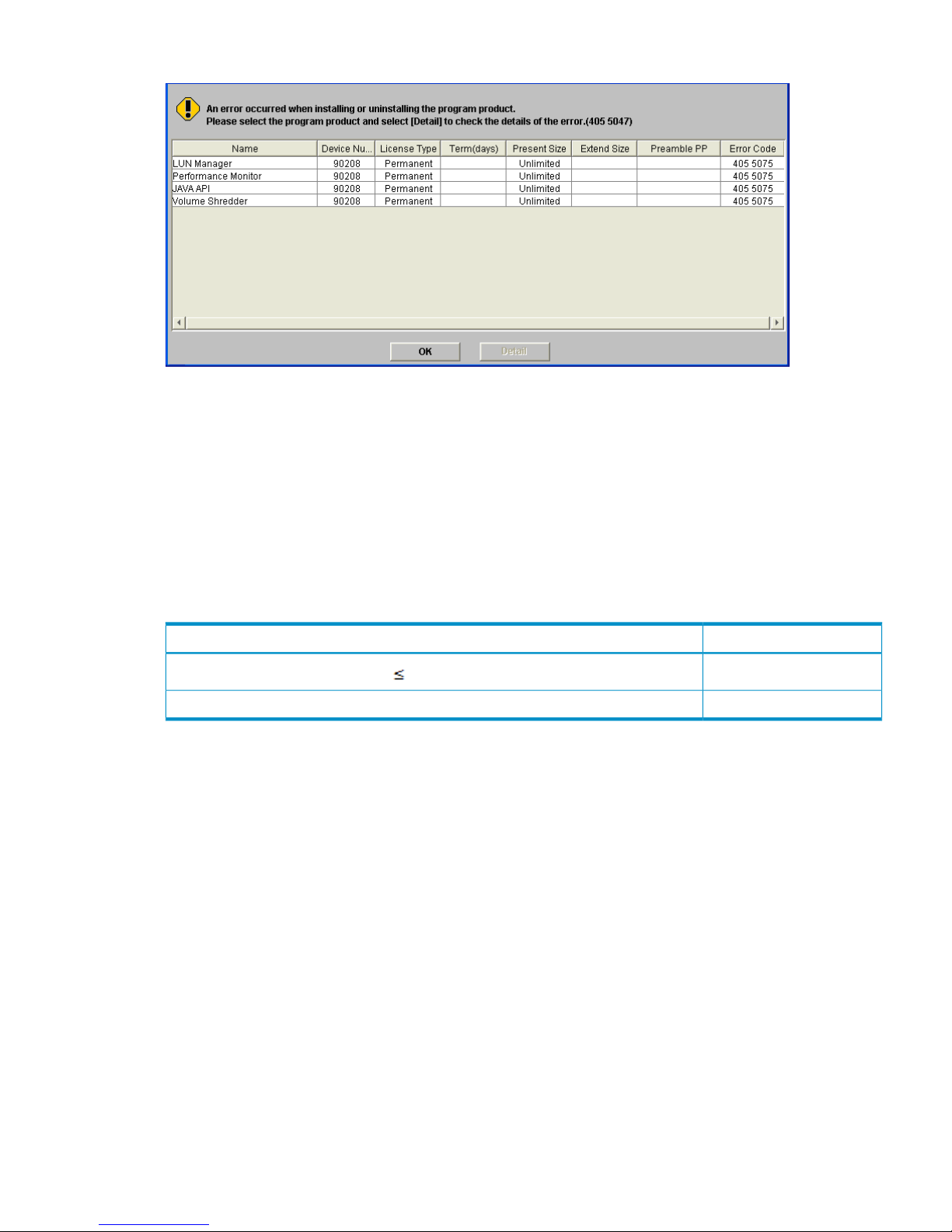
Figure 50 Install/Uninstall Error Dialog Box
Enabling Options Automatically
When the licensed capacity exceeds the mounted capacity after you reduce the number of disk
drives, or when the licensed capacity exceeds the used capacity after you delete pairs or pools,
you can automatically enable the available Remote Web Console options using the Available
button.
Whether the options can be enabled using the Available button depends on the relationship
between the licensed capacity and the mounted capacity of the disk drives (or the used capacity
of the pairs or pools). Table 29 (page 99) shows the condition to enable the Available button.
Table 29 Condition to Enable Available Button
Available ButtonRelationship between Licensed Capacity and Mounted Capacity (or Used Capacity)
Available
Mounted capacity or used capacity Licensed capacity
Not availableMounted capacity or used capacity > Licensed capacity
To install Remote Web Console options automatically on Remote Web Console using the Available
button:
1. Log in to Remote Web Console and open the License Key window (see “License Key Window”
(page 56)).
2. Change to Modify mode.
3. From Mode, click Available.
4. Click Install.
In the License Key list, the row of the options that can be enabled changes to blue bold italics,
and the Status column changes to Install.
5. Click Apply (or Cancel). The status of the enabled options changes to Installed.
Enabling or Disabling a License
When you want to enable or disable the term key, you select Enable or Disable for the License
Status. You can also enable licenses when you install more than one program product option at
once; however, some program product options are not available because their requirements are
not satisfied. In this case, you need to satisfy the requirements first, and then enable the license.
To enable or disable a license:
1. Log in to Remote Web Console and open the License Key window (see “License Key Window”
(page 56)).
Enabling and Disabling Remote Web Console Options 99
Page 100

2. Change to Modify mode (see “Changing Between View Mode and Modify Mode” (page 41)
if you need instructions).
3. Select the option that you want to set from the list.
4. In License Status, select Enable or Disable.
5. Click Set. The row of the selected option changes to blue bold italics. If you set to Disable,
the Status column changes to Install (Disable). If you set to Enable, the Status column changes
to Install.
6. When you want to enable or disable other options, repeat steps 3 through 5.
7. Click Apply (or Cancel). The status of the program product options is changed.
Disabling Remote Web Console Options
To disable Remote Web Console options on Remote Web Console:
1. Log in to Remote Web Console and open the License Key window (see “License Key Window”
(page 56)).
2. Change to Modify mode.
3. Select the option that you want to uninstall from the list. The selected option is displayed in
reverse video.
4. From Mode, click Key Code.
5. Click Uninstall. A confirmation message is displayed.
6. Click OK (or Cancel). The row of the selected option changes to blue bold italics and also
changes the displayed status to Uninstall.
7. When you want to disable other options, repeat steps 3 through 6.
8. Click Apply (or Cancel). The status of the uninstalled option changes from Installed to Not
installed.
CAUTION:
• On rare occasions, a program product option that is listed as Not Installed, but still has
available licensed capacity (shown as XX TB), might remain in the list. In this case, select that
option and select Uninstall to reset information about the option.
• When you uninstall Data Retention Utility, an error might occur even if the Permitted Volumes
column in the License Key window indicates that the licensed capacity is 0TB (zero terabyte).
To remove the error and continue uninstallation, take the following steps:
1. Open the Data Retention window and then find logical volumes that are unusable as
S-VOLs (secondary volumes). For detailed instructions, see the HP StorageWorks
XP24000/XP20000 Data Retention Utility User Guide.
2. Change the settings for the logical volumes so that the logical volumes are usable as
S-VOLs. For detailed instructions, see the HP StorageWorks XP24000/XP20000 Data
Retention Utility User Guide.
3. Return to the License Key window and then uninstall Data Retention Utility.
Launching the Desired Option
You must install the options (see “Enabling and Disabling Remote Web Console Options” (page 97))
to use the options.
To launch a particular option, select Go, option name or function name, and then the tab name
of each window from the menu bar of the Remote Web Console main window.
The Go menu displays the names of program product options or functions (see “Go Menu”
(page 53). Each name in the Go menu has a submenu that displays the tab name of the options
or functions.
100 Performing Remote Web Console Operations
 Loading...