

HP StorageWorks SAN Switch 2/8V, StorageWorks SAN Switch 2/16V, StorageWorks SAN Switch 2/16N, StorageWorks SAN Switch 4/32 Installation Manual
Page 1

HP StorageWorks
SAN Switch 2/8V, 2/16V, 2/16N
and 4/32 installation guide
Part number: AA-RVULC-TE
Third edition: January 2005
Page 2

Legal and notice information
© Copyright 2005 Hewlett-Packard Development Company, L.P.
Hewlett-Packard Company makes no warranty of any kind with regard to this material, including, but not limited to, the implied
warranties of merchantability and fitness for a particular purpose. Hewlett-Packard shall not be liable for errors contained herein or
for incidental or consequential damages in connection with the furnishing, performance, or use of this material.
This document contains proprietary information, which is protected by copyright. No part of this document may be photocopied,
reproduced, or translated into another language without the prior written consent of Hewlett-Packard. The information is provided
“as is” without warranty of any kind and is subject to change without notice. The only warranties for HP products and services are
set forth in the express warranty statements accompanying such products and services. Nothing herein should be construed as
constituting an additional warranty. HP shall not be liable for technical or editorial errors or omissions contained herein.
Compaq Computer Corporation is a wholly-owned subsidiary of Hewlett-Packard Company.
Adobe and Acrobat are trademarks of Adobe Systems Incorporated.
Microsoft, MS-DOS, MS Windows, Windows, and Windows NT are U.S. registered trademarks of Microsoft Corporation.
UNIX is a registered trademark of The Open Group.
Printed in the U.S.A.
SAN Switch 2/8V, 2/16V, 2/16N and 4/32 installation guide
Page 3

Contents
About this guide. . . . . . . . . . . . . . . . . . . . . . . . . . . . . . . . . . . . . . . 9
Overview. . . . . . . . . . . . . . . . . . . . . . . . . . . . . . . . . . . . . . . . . . . . . . . . . . . . . . . . . . . . 10
Intended audience . . . . . . . . . . . . . . . . . . . . . . . . . . . . . . . . . . . . . . . . . . . . . . . . . . . 10
Related documentation . . . . . . . . . . . . . . . . . . . . . . . . . . . . . . . . . . . . . . . . . . . . . . . . 10
Conventions. . . . . . . . . . . . . . . . . . . . . . . . . . . . . . . . . . . . . . . . . . . . . . . . . . . . . . . . . . 11
Document conventions . . . . . . . . . . . . . . . . . . . . . . . . . . . . . . . . . . . . . . . . . . . . . . . . 11
Document conventions . . . . . . . . . . . . . . . . . . . . . . . . . . . . . . . . . . . . . . . . . . . 11
Text symbols . . . . . . . . . . . . . . . . . . . . . . . . . . . . . . . . . . . . . . . . . . . . . . . . . . . . . . . 12
Equipment symbols . . . . . . . . . . . . . . . . . . . . . . . . . . . . . . . . . . . . . . . . . . . . . . . . . . 13
Rack stability . . . . . . . . . . . . . . . . . . . . . . . . . . . . . . . . . . . . . . . . . . . . . . . . . . . . . . . . . 14
Getting help. . . . . . . . . . . . . . . . . . . . . . . . . . . . . . . . . . . . . . . . . . . . . . . . . . . . . . . . . . 14
HP technical support . . . . . . . . . . . . . . . . . . . . . . . . . . . . . . . . . . . . . . . . . . . . . . . . . 14
HP Storage web site. . . . . . . . . . . . . . . . . . . . . . . . . . . . . . . . . . . . . . . . . . . . . . . . . . 15
HP authorized reseller . . . . . . . . . . . . . . . . . . . . . . . . . . . . . . . . . . . . . . . . . . . . . . . . 15
Contents
1 Overview. . . . . . . . . . . . . . . . . . . . . . . . . . . . . . . . . . . . . . . . . 17
SAN Switch 2/8V, 2/16V and 2/16N models . . . . . . . . . . . . . . . . . . . . . . . . . . . . . . . . . 18
SAN Switch 2/8V, 2/16V and 2/16N features . . . . . . . . . . . . . . . . . . . . . . . . . . . . . . 18
SAN Switch 2/8V, 2/16V and 2/16N chassis. . . . . . . . . . . . . . . . . . . . . . . . . . . . . . . 19
SAN Switch 2/8V, 2/16V and 2/16N—port side . . . . . . . . . . . . . . . . . . . . . . . . . . 19
SAN Switch 2/8V, 2/16V and 2/16N—nonport side . . . . . . . . . . . . . . . . . . . . . . . 20
SAN Switch 4/32 models . . . . . . . . . . . . . . . . . . . . . . . . . . . . . . . . . . . . . . . . . . . . . . . . 21
SAN Switch 4/32 features . . . . . . . . . . . . . . . . . . . . . . . . . . . . . . . . . . . . . . . . . . . . . 21
SAN Switch 4/32 chassis. . . . . . . . . . . . . . . . . . . . . . . . . . . . . . . . . . . . . . . . . . . . . . 22
SAN Switch 4/32—port side . . . . . . . . . . . . . . . . . . . . . . . . . . . . . . . . . . . . . . . . . 22
SAN Switch 4/32—nonport side . . . . . . . . . . . . . . . . . . . . . . . . . . . . . . . . . . . . . . 23
Upgrading SAN Switch 4/32 ports . . . . . . . . . . . . . . . . . . . . . . . . . . . . . . . . . . . . . . . . . 24
SAN Switch licensing . . . . . . . . . . . . . . . . . . . . . . . . . . . . . . . . . . . . . . . . . . . . . . . . . . . 25
ISL Trunking groups. . . . . . . . . . . . . . . . . . . . . . . . . . . . . . . . . . . . . . . . . . . . . . . . . . . . . 26
SAN Switch supported (optional) features . . . . . . . . . . . . . . . . . . . . . . . . . . . . . . . . . . . . . 27
SAN Switch optional kits . . . . . . . . . . . . . . . . . . . . . . . . . . . . . . . . . . . . . . . . . . . . . . . . . 28
SAN Switch 2/8V, 2/16V, 2/16N and 4/32 installation guide 3
Page 4

2 Installing and configuring. . . . . . . . . . . . . . . . . . . . . . . . . . . . . .31
SAN Switch shipping carton contents . . . . . . . . . . . . . . . . . . . . . . . . . . . . . . . . . . . . . . . . . 32
SAN Switch shipping carton contents checklist . . . . . . . . . . . . . . . . . . . . . . . . . . . . . . . . 32
Installation and safety considerations . . . . . . . . . . . . . . . . . . . . . . . . . . . . . . . . . . . . . . . . . 34
Electrical considerations . . . . . . . . . . . . . . . . . . . . . . . . . . . . . . . . . . . . . . . . . . . . . . . . 34
Environmental considerations . . . . . . . . . . . . . . . . . . . . . . . . . . . . . . . . . . . . . . . . . . . . 34
Rack specifications . . . . . . . . . . . . . . . . . . . . . . . . . . . . . . . . . . . . . . . . . . . . . . . . . 35
Cooling considerations. . . . . . . . . . . . . . . . . . . . . . . . . . . . . . . . . . . . . . . . . . . . . . . . . 35
Installing as a stand-alone device . . . . . . . . . . . . . . . . . . . . . . . . . . . . . . . . . . . . . . . . . . . . 36
Installing the switch in a rack using the SAN Switch Rack Mount Kit . . . . . . . . . . . . . . . . . . . . 37
Cabling and configuring the SAN Switch . . . . . . . . . . . . . . . . . . . . . . . . . . . . . . . . . . . . . . 50
Recommendations for cable management . . . . . . . . . . . . . . . . . . . . . . . . . . . . . . . . . . . . 50
Connecting the SAN Switch to the fabric. . . . . . . . . . . . . . . . . . . . . . . . . . . . . . . . . . . . . . . 51
Items required . . . . . . . . . . . . . . . . . . . . . . . . . . . . . . . . . . . . . . . . . . . . . . . . . . . . . . . 51
Making a serial connection. . . . . . . . . . . . . . . . . . . . . . . . . . . . . . . . . . . . . . . . . . . . . . 51
Logging in . . . . . . . . . . . . . . . . . . . . . . . . . . . . . . . . . . . . . . . . . . . . . . . . . . . . . . . . . 53
Setting the IP address . . . . . . . . . . . . . . . . . . . . . . . . . . . . . . . . . . . . . . . . . . . . . . . . . . 54
Creating an Ethernet connection . . . . . . . . . . . . . . . . . . . . . . . . . . . . . . . . . . . . . . . . . . 55
Modifying the Fibre Channel domain ID (Optional) . . . . . . . . . . . . . . . . . . . . . . . . . . . . . 56
Installing the SFP transceivers . . . . . . . . . . . . . . . . . . . . . . . . . . . . . . . . . . . . . . . . . . . . 57
Connecting the cables . . . . . . . . . . . . . . . . . . . . . . . . . . . . . . . . . . . . . . . . . . . . . . . . . 57
Verifying the configuration . . . . . . . . . . . . . . . . . . . . . . . . . . . . . . . . . . . . . . . . . . . . . . 58
Backing up the configuration. . . . . . . . . . . . . . . . . . . . . . . . . . . . . . . . . . . . . . . . . . . . . 58
Setting the switch date and time . . . . . . . . . . . . . . . . . . . . . . . . . . . . . . . . . . . . . . . . . . 58
Synchronizing local time with an external source. . . . . . . . . . . . . . . . . . . . . . . . . . . . . . . 59
Correcting the time zone of a switch . . . . . . . . . . . . . . . . . . . . . . . . . . . . . . . . . . . . . . . 59
3 Managing SAN switches . . . . . . . . . . . . . . . . . . . . . . . . . . . . . .61
Powering on and off . . . . . . . . . . . . . . . . . . . . . . . . . . . . . . . . . . . . . . . . . . . . . . . . . . . . . 62
SAN Switch 2/8V . . . . . . . . . . . . . . . . . . . . . . . . . . . . . . . . . . . . . . . . . . . . . . . . . . . . 62
SAN Switch 2/16V, 2/16N and 4/32 . . . . . . . . . . . . . . . . . . . . . . . . . . . . . . . . . . . . . 62
Management features . . . . . . . . . . . . . . . . . . . . . . . . . . . . . . . . . . . . . . . . . . . . . . . . . . . . 63
Managing SAN Switches from a single management station . . . . . . . . . . . . . . . . . . . . . . . . . 64
Interpreting LED activity . . . . . . . . . . . . . . . . . . . . . . . . . . . . . . . . . . . . . . . . . . . . . . . . . . . 64
SAN Switch 2/8V, 2/16V and 2/16N LEDs. . . . . . . . . . . . . . . . . . . . . . . . . . . . . . . . . . . . 65
SAN Switch 2/8V, 2/16V and 2/16N LED patterns . . . . . . . . . . . . . . . . . . . . . . . . . . . . . . 67
System and power LED patterns. . . . . . . . . . . . . . . . . . . . . . . . . . . . . . . . . . . . . . . . . . . 67
Port LED patterns . . . . . . . . . . . . . . . . . . . . . . . . . . . . . . . . . . . . . . . . . . . . . . . . . . . . . 68
Ethernet LED patterns . . . . . . . . . . . . . . . . . . . . . . . . . . . . . . . . . . . . . . . . . . . . . . . . . . 69
SAN Switch 4/32 LEDs—port side . . . . . . . . . . . . . . . . . . . . . . . . . . . . . . . . . . . . . . . . . . . 70
SAN Switch 4/32 LEDs—nonport side . . . . . . . . . . . . . . . . . . . . . . . . . . . . . . . . . . . . . . . . 74
POST and boot specifications. . . . . . . . . . . . . . . . . . . . . . . . . . . . . . . . . . . . . . . . . . . . . . . 76
POST . . . . . . . . . . . . . . . . . . . . . . . . . . . . . . . . . . . . . . . . . . . . . . . . . . . . . . . . . . . . . 76
Boot. . . . . . . . . . . . . . . . . . . . . . . . . . . . . . . . . . . . . . . . . . . . . . . . . . . . . . . . . . . . . . 76
Interpreting POST results . . . . . . . . . . . . . . . . . . . . . . . . . . . . . . . . . . . . . . . . . . . . . . . . . . 77
Diagnostic tests . . . . . . . . . . . . . . . . . . . . . . . . . . . . . . . . . . . . . . . . . . . . . . . . . . . . . . . . 77
Contents4
Page 5

4 Installing field-replaceable units . . . . . . . . . . . . . . . . . . . . . . . . . 79
Replacing the SAN Switch 4/32 power supply . . . . . . . . . . . . . . . . . . . . . . . . . . . . . . . . . 80
Items required . . . . . . . . . . . . . . . . . . . . . . . . . . . . . . . . . . . . . . . . . . . . . . . . . . . . . . 82
Procedure . . . . . . . . . . . . . . . . . . . . . . . . . . . . . . . . . . . . . . . . . . . . . . . . . . . . . . . . . 82
Replacing the fan assembly in the
SAN Switch 4/32 . . . . . . . . . . . . . . . . . . . . . . . . . . . . . . . . . . . . . . . . . . . . . . . . . . . . . 85
Items required . . . . . . . . . . . . . . . . . . . . . . . . . . . . . . . . . . . . . . . . . . . . . . . . . . . . . . 87
Procedure . . . . . . . . . . . . . . . . . . . . . . . . . . . . . . . . . . . . . . . . . . . . . . . . . . . . . . . . . 87
Replacing SFPs. . . . . . . . . . . . . . . . . . . . . . . . . . . . . . . . . . . . . . . . . . . . . . . . . . . . . . . . 89
A Regulatory compliance notices . . . . . . . . . . . . . . . . . . . . . . . . . . 91
FCC EMC statement (USA). . . . . . . . . . . . . . . . . . . . . . . . . . . . . . . . . . . . . . . . . . . . . . . . 91
EMC statement (Canada). . . . . . . . . . . . . . . . . . . . . . . . . . . . . . . . . . . . . . . . . . . . . . . . . 92
EMC statement (European Union) . . . . . . . . . . . . . . . . . . . . . . . . . . . . . . . . . . . . . . . . . . . 92
European union notice . . . . . . . . . . . . . . . . . . . . . . . . . . . . . . . . . . . . . . . . . . . . . . . . . . 92
Germany noise declaration . . . . . . . . . . . . . . . . . . . . . . . . . . . . . . . . . . . . . . . . . . . . . . . 92
VCCI EMC statement (Japan) . . . . . . . . . . . . . . . . . . . . . . . . . . . . . . . . . . . . . . . . . . . . . . 93
Japanese power cord statement . . . . . . . . . . . . . . . . . . . . . . . . . . . . . . . . . . . . . . . . . . . . 93
RRL EMC statement (Korea) . . . . . . . . . . . . . . . . . . . . . . . . . . . . . . . . . . . . . . . . . . . . . . . 94
Laser safety . . . . . . . . . . . . . . . . . . . . . . . . . . . . . . . . . . . . . . . . . . . . . . . . . . . . . . . . . . 95
Battery replacement notice. . . . . . . . . . . . . . . . . . . . . . . . . . . . . . . . . . . . . . . . . . . . . . . . 96
B Electrostatic discharge . . . . . . . . . . . . . . . . . . . . . . . . . . . . . . . . 97
Grounding methods . . . . . . . . . . . . . . . . . . . . . . . . . . . . . . . . . . . . . . . . . . . . . . . . . . . . 97
C SAN Switch technical specifications . . . . . . . . . . . . . . . . . . . . . . 99
General specifications. . . . . . . . . . . . . . . . . . . . . . . . . . . . . . . . . . . . . . . . . . . . . . . . . . 100
Weight and physical dimensions . . . . . . . . . . . . . . . . . . . . . . . . . . . . . . . . . . . . . . . . . . 102
Facility requirements . . . . . . . . . . . . . . . . . . . . . . . . . . . . . . . . . . . . . . . . . . . . . . . . . . . 103
Environmental requirements . . . . . . . . . . . . . . . . . . . . . . . . . . . . . . . . . . . . . . . . . . . . . . 104
Data transmission ranges. . . . . . . . . . . . . . . . . . . . . . . . . . . . . . . . . . . . . . . . . . . . . . . . 105
Data transmissions for the 2/8V, 2/16V and 2/16N . . . . . . . . . . . . . . . . . . . . . . . . . 105
Data transmissions for the 4/32 . . . . . . . . . . . . . . . . . . . . . . . . . . . . . . . . . . . . . . . . 105
Fibre Channel port specifications . . . . . . . . . . . . . . . . . . . . . . . . . . . . . . . . . . . . . . . . . . 107
2/8V, 2/16V and 2/16N Fibre Channel port specifications . . . . . . . . . . . . . . . . . . . . 107
4/32 Fibre Channel port specifications . . . . . . . . . . . . . . . . . . . . . . . . . . . . . . . . . . . 107
Serial port specifications . . . . . . . . . . . . . . . . . . . . . . . . . . . . . . . . . . . . . . . . . . . . . . . . 107
Power supply specifications . . . . . . . . . . . . . . . . . . . . . . . . . . . . . . . . . . . . . . . . . . . . . . 109
Memory . . . . . . . . . . . . . . . . . . . . . . . . . . . . . . . . . . . . . . . . . . . . . . . . . . . . . . . . . . . 110
Supported SFPs . . . . . . . . . . . . . . . . . . . . . . . . . . . . . . . . . . . . . . . . . . . . . . . . . . . . . . 111
Supported HBAs. . . . . . . . . . . . . . . . . . . . . . . . . . . . . . . . . . . . . . . . . . . . . . . . . . . . . . 111
Glossary . . . . . . . . . . . . . . . . . . . . . . . . . . . . . . . . . . . . . . . . . . 113
Index . . . . . . . . . . . . . . . . . . . . . . . . . . . . . . . . . . . . . . . . . . . . 123
SAN Switch 2/8V, 2/16V, 2/16N and 4/32 installation guide 5
Page 6

Figures
1 Port side of SAN Switch 2/8V. . . . . . . . . . . . . . . . . . . . . . . . . . . . . . . . . . . . . . . . . . . 20
2 Port side of SAN Switch 2/16V and 2/16N. . . . . . . . . . . . . . . . . . . . . . . . . . . . . . . . . 20
3 Port side of SAN Switch 4/32. . . . . . . . . . . . . . . . . . . . . . . . . . . . . . . . . . . . . . . . . . . 22
4 SAN Switch 4/32—nonport side. . . . . . . . . . . . . . . . . . . . . . . . . . . . . . . . . . . . . . . . . 23
5 Trunking groups. . . . . . . . . . . . . . . . . . . . . . . . . . . . . . . . . . . . . . . . . . . . . . . . . . . . . 26
6 SAN Switch shipping carton contents . . . . . . . . . . . . . . . . . . . . . . . . . . . . . . . . . . . . . . 32
7 Installing the rear mounting brackets (HP 10,000 series). . . . . . . . . . . . . . . . . . . . . . . . . 40
8 Installing the rear mounting brackets (HP System/e rack-left rear upright) . . . . . . . . . . . . . 41
9 Installing the outer rails (HP 10,000 series) . . . . . . . . . . . . . . . . . . . . . . . . . . . . . . . . . . 42
10 Assembling the outer rails (HP 10,000 series) . . . . . . . . . . . . . . . . . . . . . . . . . . . . . . . . 43
11 Assembling the outer rails (HP System/e rack). . . . . . . . . . . . . . . . . . . . . . . . . . . . . . . . 44
12 Securing the inner rails to the SAN Switch 2/8V with plenum . . . . . . . . . . . . . . . . . . . . . 46
13 Securing the inner rails to the SAN Switch 2/16V . . . . . . . . . . . . . . . . . . . . . . . . . . . . . 47
14 Securing the inner rails to the SAN Switch 4/32 . . . . . . . . . . . . . . . . . . . . . . . . . . . . . . 47
15 Installing the switch into a rack (HP 10,000 series rack) . . . . . . . . . . . . . . . . . . . . . . . . . 48
16 Installing the switch into a rack (HP System/e rack) . . . . . . . . . . . . . . . . . . . . . . . . . . . . 49
17 Connecting the serial cable to a SAN Switch 2/16V . . . . . . . . . . . . . . . . . . . . . . . . . . . 52
18 Connecting SAN Switch 2/16V power cords . . . . . . . . . . . . . . . . . . . . . . . . . . . . . . . . 53
19 Connecting the Ethernet cable to the SAN Switch 2/16V . . . . . . . . . . . . . . . . . . . . . . . . 55
20 SAN Switch 2/8V LED locations . . . . . . . . . . . . . . . . . . . . . . . . . . . . . . . . . . . . . . . . . 65
21 SAN Switch 2/16V and 2/16N LED locations . . . . . . . . . . . . . . . . . . . . . . . . . . . . . . . 66
22 SAN Switch 4/32 port side LEDs. . . . . . . . . . . . . . . . . . . . . . . . . . . . . . . . . . . . . . . . . 71
23 SAN Switch 4/32 nonport side LEDs . . . . . . . . . . . . . . . . . . . . . . . . . . . . . . . . . . . . . . 74
24 SAN Switch 4/32 power supplies on the nonport side. . . . . . . . . . . . . . . . . . . . . . . . . . 80
25 Inserting the power supply in the SAN Switch 4/32. . . . . . . . . . . . . . . . . . . . . . . . . . . . 83
26 SAN Switch 4/32 fan assemblies on the nonport side . . . . . . . . . . . . . . . . . . . . . . . . . . 85
27 Inserting the fan assembly. . . . . . . . . . . . . . . . . . . . . . . . . . . . . . . . . . . . . . . . . . . . . . 88
28 Installing or removing an SFP . . . . . . . . . . . . . . . . . . . . . . . . . . . . . . . . . . . . . . . . . . . 90
Tables
1 SAN Switch 2/8V port side components . . . . . . . . . . . . . . . . . . . . . . . . . . . . . . . . . . . 20
2 SAN Switch 2/16V and 2/16N port side components . . . . . . . . . . . . . . . . . . . . . . . . . 20
3 SAN Switch 4/32 port side components . . . . . . . . . . . . . . . . . . . . . . . . . . . . . . . . . . . 22
4 SAN Switch 4/32 nonport side components. . . . . . . . . . . . . . . . . . . . . . . . . . . . . . . . . 24
5 Optional kits . . . . . . . . . . . . . . . . . . . . . . . . . . . . . . . . . . . . . . . . . . . . . . . . . . . . . . . 28
6 SAN Switch shipping carton contents checklist . . . . . . . . . . . . . . . . . . . . . . . . . . . . . . . 33
7 SAN Switch Rack Mount Kit hardware . . . . . . . . . . . . . . . . . . . . . . . . . . . . . . . . . . . . . 38
8 Number of screws required to assemble the inner rails. . . . . . . . . . . . . . . . . . . . . . . . . . 45
9 tsTimeZone command parameter selection . . . . . . . . . . . . . . . . . . . . . . . . . . . . . . . . 60
10 Management options . . . . . . . . . . . . . . . . . . . . . . . . . . . . . . . . . . . . . . . . . . . . . . . . . 63
11 SAN Switch 2/8V LED Locations . . . . . . . . . . . . . . . . . . . . . . . . . . . . . . . . . . . . . . . . . 65
12 SAN Switch 2/16V and 2/16N LED locations . . . . . . . . . . . . . . . . . . . . . . . . . . . . . . . 66
13 System LED patterns during normal operation . . . . . . . . . . . . . . . . . . . . . . . . . . . . . . . . 67
14 Port LED patterns during normal operation . . . . . . . . . . . . . . . . . . . . . . . . . . . . . . . . . . 68
15 Ethernet LED patterns . . . . . . . . . . . . . . . . . . . . . . . . . . . . . . . . . . . . . . . . . . . . . . . . . 69
Contents6
Page 7

16 SAN Switch 4/32 port side LEDs. . . . . . . . . . . . . . . . . . . . . . . . . . . . . . . . . . . . . . . . . 71
17 SAN Switch 4/32 port side LED patterns during normal operation. . . . . . . . . . . . . . . . . . 72
18 SAN Switch 4/32 nonport side LEDs . . . . . . . . . . . . . . . . . . . . . . . . . . . . . . . . . . . . . . 74
19 Nonport side LED patterns during normal operation. . . . . . . . . . . . . . . . . . . . . . . . . . . . 75
20 SAN Switch 4/32 nonport side LEDs . . . . . . . . . . . . . . . . . . . . . . . . . . . . . . . . . . . . . . 80
21 Power supply status LEDs . . . . . . . . . . . . . . . . . . . . . . . . . . . . . . . . . . . . . . . . . . . . . . 81
22 Power supply components. . . . . . . . . . . . . . . . . . . . . . . . . . . . . . . . . . . . . . . . . . . . . . 83
23 Fan assemblies . . . . . . . . . . . . . . . . . . . . . . . . . . . . . . . . . . . . . . . . . . . . . . . . . . . . . 85
24 Fan status LED behavior . . . . . . . . . . . . . . . . . . . . . . . . . . . . . . . . . . . . . . . . . . . . . . . 86
25 Fan assemblies . . . . . . . . . . . . . . . . . . . . . . . . . . . . . . . . . . . . . . . . . . . . . . . . . . . . . 88
26 General specifications . . . . . . . . . . . . . . . . . . . . . . . . . . . . . . . . . . . . . . . . . . . . . . . 101
27 SAN Switch specifications . . . . . . . . . . . . . . . . . . . . . . . . . . . . . . . . . . . . . . . . . . . . 103
28 Facility requirements . . . . . . . . . . . . . . . . . . . . . . . . . . . . . . . . . . . . . . . . . . . . . . . . 104
29 Environmental requirements. . . . . . . . . . . . . . . . . . . . . . . . . . . . . . . . . . . . . . . . . . . . 105
30 Laser data transmission ranges for the 2/8V, 2/16V and 2/16N . . . . . . . . . . . . . . . . . 106
31 Laser data transmission ranges for the 4/32 . . . . . . . . . . . . . . . . . . . . . . . . . . . . . . . . 106
32 Cabling pinouts. . . . . . . . . . . . . . . . . . . . . . . . . . . . . . . . . . . . . . . . . . . . . . . . . . . . 109
33 Power supply specifications. . . . . . . . . . . . . . . . . . . . . . . . . . . . . . . . . . . . . . . . . . . . 110
34 2/8V, 2/16V and 2/16N Memory specifications . . . . . . . . . . . . . . . . . . . . . . . . . . . . 111
35 4/32 Memory specifications. . . . . . . . . . . . . . . . . . . . . . . . . . . . . . . . . . . . . . . . . . . 112
SAN Switch 2/8V, 2/16V, 2/16N and 4/32 installation guide 7
Page 8

Contents8
Page 9

About this guide
This installation guide provides information to help you set up and configure the following
HP switches:
• HP StorageWorks SAN Switch 2/8V
• HP StorageWorks SAN Switch 2/16V
• HP StorageWorks SAN Switch 2/16N
• HP StorageWorks SAN Switch 4/32
NOTE: Throughout this guide, information about the SAN Switch 2/16V is applicable to the
SAN Switch 2/16N, unless otherwise noted.
“About this Guide” topics include:
• Overview, page 10
• Conventions, page 11
• Rack stability, page 14
SAN Switch 2/8V, 2/16V, 2/16N and 4/32 installation guide 9
Page 10

Overview
This section covers the following topics:
• Intended audience
• Related documentation
Intended audience
This guide is intended for use by system administrators and technicians who are experienced
with the following:
• Configuration aspects of customer Storage Area Network (SAN) fabric
• Customer host environment, such as Microsoft Windows or IBM AIX
• The built-in Graphical User Interface (GUI), Advanced Web Tools, for configuring the
switches through a supported web browser
Related documentation
Documentation, including white papers and best practices documents, is available via the HP
website. Please go to:
http://www.hp.com/country/us/eng/prodserv/storage.html
To access SAN Switch related documents:
1. Locate the Networked storage section of the web page.
2. Under Networked storage, go to the By type subsection.
3. Click SAN infrastructure. The SAN infrastructure page displays.
4. Locate the Fibre Channel Switches section.
5. Locate the B-Series Fabric subsection, then go to the Entry-level subsection.
6. Select SAN Switch 2/8V, SAN Switch 2/16V, SAN Switch 2/16N or SAN
Switch 4/32. The switch overview page displays.
7. Go to the product information section, located on the far right side of the web page.
8. Click technical documents.
9. Follow the onscreen instructions to download the applicable documents.
About this guide10
Page 11

Conventions
Conventions consist of the following:
• Document conventions
• Text symbols
• Equipment symbols
Document conventions
Review the following document conventions.
Document conventions
Element Convention
Cross-reference links Blue text: Figure 1
Key and field names, menu items,
buttons, and dialog box titles
File names, application names, and text
emphasis
User input, command and directory
names, and system responses (output
and messages)
Variables <monospace, italic font>
Web site addresses Blue, underlined sans serif font text:
Bold
Italics
Monospace font
COMMAND NAMES are uppercase
monospace font unless they are case
sensitive
http://www.hp.com
SAN Switch 2/8V, 2/16V, 2/16N and 4/32 installation guide 11
Page 12
Text symbols
The following symbols may be found in the text of this guide. They have the following
meanings.
WARNING! Text set off in this manner indicates that failure to follow directions in the warning
could result in bodily harm or death.
CAUTION: Text set off in this manner indicates that failure to follow directions could result in
damage to equipment or data.
NOTE: Text set off in this manner presents commentary, sidelights, or interesting points of
information.
TIP: Provides helpful hints and shortcuts.
About this guide12
Page 13
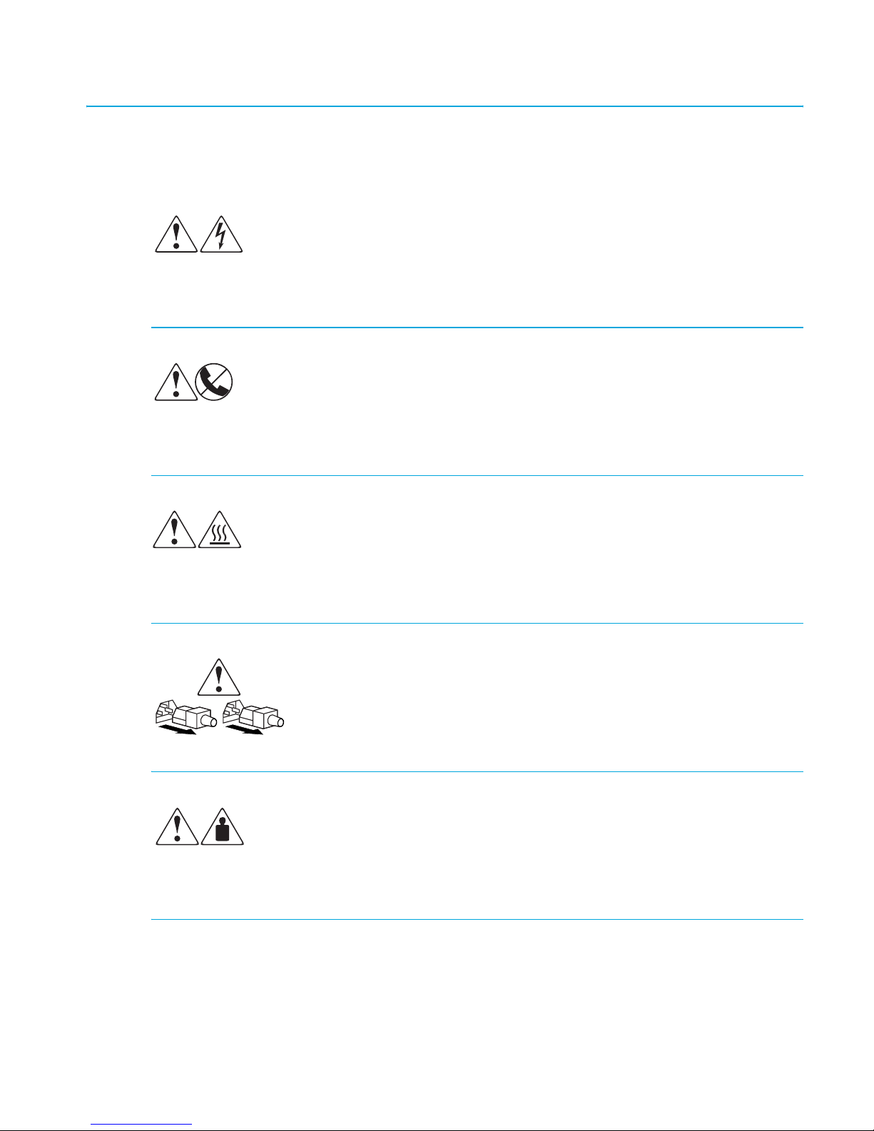
Equipment symbols
The following equipment symbols may be found on hardware for which this guide pertains.
They have the following meanings.
Any enclosed surface or area of the equipment marked with these symbols
indicates the presence of electrical shock hazards. Enclosed area contains no
operator serviceable parts.
WARNING: To reduce the risk of personal injury from electrical shock hazards, do
not open this enclosure.
Any RJ-45 receptacle marked with these symbols indicates a network interface
connection.
WARNING: To reduce the risk of electrical shock, fire, or damage to the
equipment, do not plug telephone or telecommunications connectors into this
receptacle.
Any surface or area of the equipment marked with these symbols indicates the
presence of a hot surface or hot component. Contact with this surface could result
in injury.
WARNING: To reduce the risk of personal injury from a hot component, allow the
surface to cool before touching.
Power supplies or systems marked with these symbols indicate the presence
of multiple sources of power.
WARNING: To reduce the risk of personal injury from electrical shock,
remove all power cords to completely disconnect power from the power
supplies and systems.
Any product or assembly marked with these symbols indicates that the component
exceeds the recommended weight for one individual to handle safely.
WARNING: To reduce the risk of personal injury or damage to the equipment,
observe local occupational health and safety requirements and guidelines for
manually handling material.
SAN Switch 2/8V, 2/16V, 2/16N and 4/32 installation guide 13
Page 14

Rack stability
Rack stability protects personnel and equipment.
WARNING! To reduce the risk of personal injury or damage to the equipment, be sure that:
• The leveling jacks are extended to the floor.
• The full weight of the rack rests on the leveling jacks.
• In single rack installations, the stabilizing feet are attached to the rack.
• In multiple rack installations, the racks are coupled.
• Only one rack component is extended at any time. A rack may become unstable if
more than one rack component is extended for any reason.
Getting help
If you still have a question after reading this guide, contact an HP authorized service provider
or access our web site:
http://www.hp.com
.
HP technical support
Telephone numbers for worldwide technical support are listed on the following HP web site:
http://www.hp.com/support/
NOTE: For continuous quality improvement, calls may be recorded or monitored.
Be sure to have the following information available before calling:
• Technical support registration number (if applicable)
• Product serial numbers
• Product model names and numbers
• Applicable error messages
• Operating system type and revision level
• Detailed, specific questions
About this guide14
. From this web site, select the country of origin.
Page 15

HP Storage web site
The HP web site has the latest information on this product, as well as the latest drivers. Access
storage at:
appropriate product or solution.
http://www.hp.com/country/us/eng/prodserv/storage.html
HP authorized reseller
For the name of your nearest HP authorized reseller:
• In the United States, call 1-800-345-1518.
• In Canada, call 1-800-263-5868.
. From this web site, select the
• Elsewhere, see the HP web site for locations and telephone numbers:
http://www.hp.com
.
SAN Switch 2/8V, 2/16V, 2/16N and 4/32 installation guide 15
Page 16

About this guide16
Page 17

1Overview
This chapter provides the following information:
• SAN Switch 2/8V, 2/16V and 2/16N models, page 18
• SAN Switch 4/32 models, page 21
• Upgrading SAN Switch 4/32 ports, page 24
• SAN Switch licensing, page 25
• ISL Trunking groups, page 26
• SAN Switch supported (optional) features, page 27
• SAN Switch optional kits, page 28
17SAN Switch 2/8V, 2/16V, 2/16N and 4/32 installation guide
Page 18

SAN Switch 2/8V, 2/16V and 2/16N models
The following lists HP StorageWorks SAN Switch 2/8V, 2/16V and 2/16N models.
• HP StorageWorks SAN Switch 2/8V and 2/16V include a Two-domain Fabric License.
Integrates Zoning and Advanced Web Tools as standard software components.
• HP StorageWorks SAN Switch 2/16N Full Fabric includes a Full-fabric License. Integrates
Zoning and Advanced Web Tools as standard software components.
• HP StorageWorks SAN Switch 2/8V or 2/16N Power Pack includes a Full-fabric License.
Integrates Zoning and Advanced Web Tools as standard software components.
Additionally, Power Pack models provide built-in licenses for all the optional software
including Advanced Performance Monitoring (APM), ISL Trunking, Extended Fabric, Remote
Switch and Fabric Watch.
NOTE: For SAN Switch 2/8V and SAN Switch 2/16V models only, purchase the Full-fabric
Upgrade License to allow four or more switches to operate within a domain.
SAN Switch 2/8V, 2/16V and 2/16N features
The SAN Switch 2/8V, SAN Switch 2/16V and SAN Switch 2/16N are Fibre Channel
switches that support link speeds up to 2 Gb/sec. The switches operate in a fabric containing
multiple switches or as the only switch in a fabric.
The SAN Switch 2/16N and SAN Switch 2/16V look the same; however, the SAN Switch
2/16N includes a Full-Fabric license. The Full-Fabric license allows more than two switches in
the domain.
NOTE: Unless otherwise noted, functionality and features for the 2/16V are applicable to the
2/16N throughout this guide.
The 2/8V, 2/16V and 2/16N provide the following features:
• Air-cooled 1U chassis. Install the switch as a stand-alone unit, or mounted in one of the
following HP custom racks:
• HP 10,000 series Rack
•HP System/e Rack
Overview18
Page 19
• 8 or 16 Fibre Channel ports, with the following characteristics:
• Automatic negotiation to the highest common speed of all devices connected to port.
• Port interfaces compatible with small form factor pluggable (SFP) transceivers, both
short wavelength (SWL) and long wavelength (LWL).
• Universal and self-configuring ports: capable of becoming an F_Port (fabric enabled),
FL_Port (fabric loop enabled), or E_Port (expansion port).
• One RS-232 serial port, designed to connect to a DTE port.
• One 10/100 Mb/sec Ethernet port with an RJ-45 connector.
• One (SAN Switch 2/8V) or two (SAN Switch 2/16V) built-in power supplies.
• A real-time clock (RTC) with 10-year battery
• Plenum, part number 5697-4919
SAN Switch 2/8V, 2/16V and 2/16N chassis
The following sections illustrate the chassis front and rear panels.
SAN Switch 2/8V, 2/16V and 2/16N—port side
You can see the physical differences between the SAN Switch 2/8V and the SAN Switch
2/16V switches in the following figures. The most noticeable difference is the number of ports.
Figure 1 shows the port side of the SAN Switch 2/8V. Table 1 identifies port side components.
All LEDs reside on the port side of the switches. The nonport side is used for air intake. The
SAN Switch enclosures have forced-air cooling, with the fans pushing the air from the nonport
side of the chassis through the enclosure, and exhausting to the port side.
See ”Interpreting LED activity” on page 64 for a complete description of switch LEDs.
321
!
0
100-240 VAC 1.0A 47-63Hz
IOIOI
152
4
Figure 1 Port side of SAN Switch 2/8V
Table 1 SAN Switch 2/8V port side components
Number Description
4
3
7
6
0018a
1 AC power receptacle
2 Ethernet port
19SAN Switch 2/8V, 2/16V, 2/16N and 4/32 installation guide
Page 20

Table 1 SAN Switch 2/8V port side components
Number Description
3 Serial port
4 Fibre Channel ports (8)
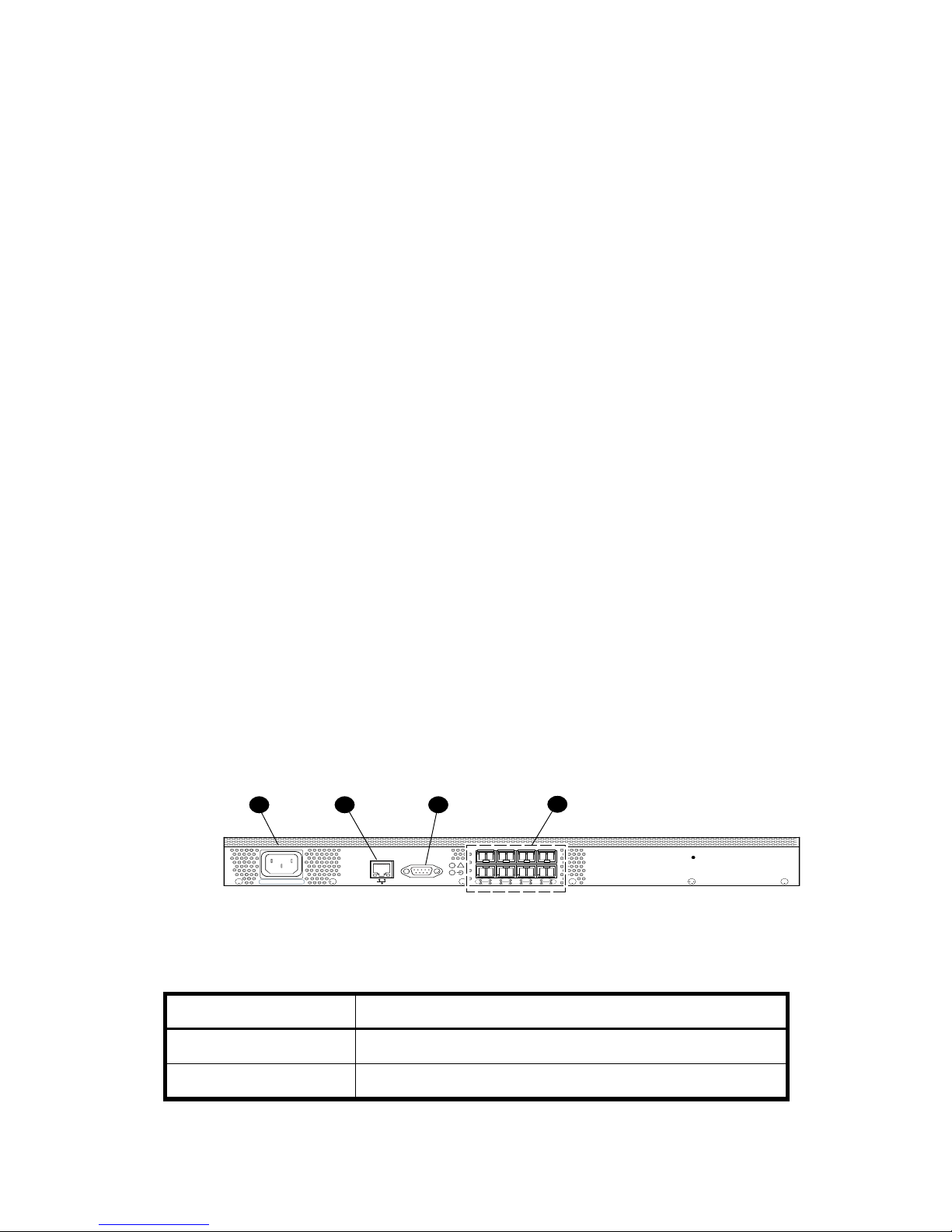
As shown in Figure 2, the SAN Switch 2/16N and 2/16V integrate sixteen ports, and a
second AC power inlet.
4321
!
0
100-240 VAC 1.0A 47-63Hz 100-240 VAC 1.0A 47-63Hz
IOIOI
152
4
3
7
6
8
91310
12
Figure 2 Port side of SAN Switch 2/16V and 2/16N
Table 2 identifies SAN Switch 2/16V port side components.
Table 2 SAN Switch 2/16V and 2/16N port side components
Number Description
1 AC power receptacle
2 Ethernet port
3 Serial port
4 FC Ports (16)
5 Second AC power receptacle
5
11
15
14
SAN Switch 2/8V, 2/16V and 2/16N—nonport side
The nonport side is used solely for air flow and for serial number labels. There are two labels
on the rear of the chassis; both contain a serial number label for the switch; the left label also
contains the 2/8V, 2/16V or 2/16N MAC address and World Wide Name (WWN).
Overview20
Page 21

SAN Switch 4/32 models
Each HP StorageWorks SAN Switch 4/32 model ships with a different number of ports
activated, as follows:
• HP StorageWorks SAN Switch 4/32 Base, 16 ports activated, includes Zoning and
Advanced Web Tools as standard software components.
• HP StorageWorks SAN Switch 4/32 Full, 32 ports activated, includes Zoning and
Advanced Web Tools as standard software components.
• HP StorageWorks SAN Switch 4/32 Power Pack, 32 ports activated, includes Advanced
Zoning and Advanced Web Tools as standard software components. Additionally, provides
integrated licenses for all optional management tools, (including Advanced Performance
Monitoring, ISL Trunking, Extended Fabric, Remote Switch and Fabric Watch).
To add ports, see ”Upgrading SAN Switch 4/32 ports” on page 24.
SAN Switch 4/32 features
The HP StorageWorks SAN Switch 4/32 provides the following features:
• Air-cooled 1U chassis
• 32 fixed auto-sensing 1-, 2-, or 4-Gbit/sec Fibre Channel ports, with the following
characteristics:
• Automatic negotiation to the highest common speed of all devices connected to port.
• Port interfaces compatible with small form factor pluggable (SFP) transceivers, both
short wavelength (SWL) and long wavelength (LWL).
• Universal and self-configuring ports: capable of becoming an F_Port (fabric enabled),
FL_Port (fabric loop enabled), or E_Port (expansion port).
• One RS-232 serial port, designed to connect to a DTE port.
• One 10/100 Mb/sec Ethernet port with an RJ-45 connector.
• Two redundant, hot-pluggable universal AC power supplies
• Three redundant, hot-pluggable fans
21SAN Switch 2/8V, 2/16V, 2/16N and 4/32 installation guide
Page 22
SAN Switch 4/32 chassis
The following sections illustrate the chassis front and rear panels.
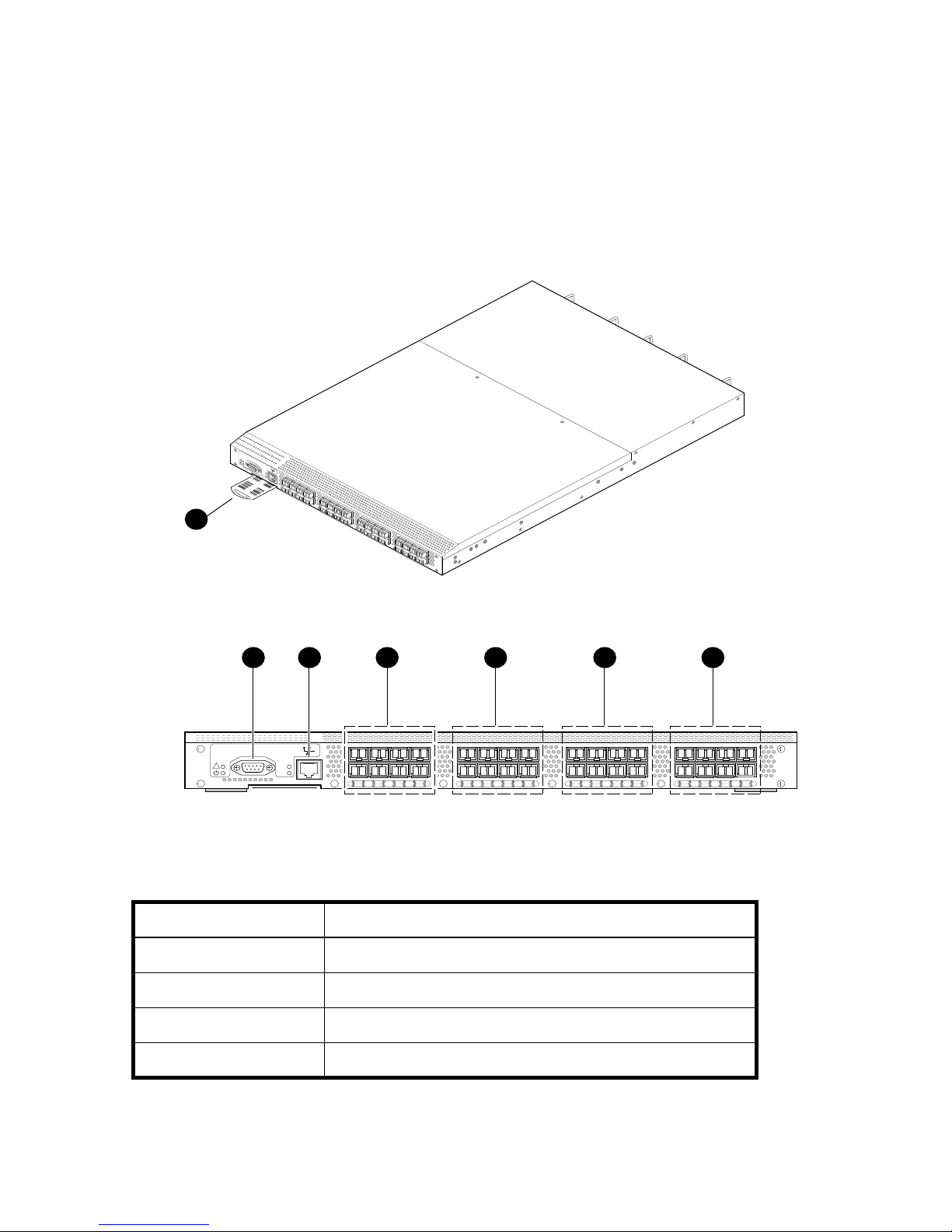
SAN Switch 4/32—port side
Figure 3 shows the port side of the SAN Switch 4/32. Table 3 identifies port side components.
!
IO
IO
I
L
N
K
S
P
D
1
4 5 6 732
IOIOI
!
LNK
SPD
0
4
152
3
7
6
8
91310
12
Figure 3 Port side of SAN Switch 4/32
Table 3 SAN Switch 4/32 port side components
Number Description
1 Switch ID pull-out tab
scale: 1/8" = 1"
11
15
14
16
20
172118
19
23
22
24
28
252926
27
31
30
MRO25009a
2 Serial port
3 Ethernet port
4 FC Ports (0-7)
Overview22
Page 23
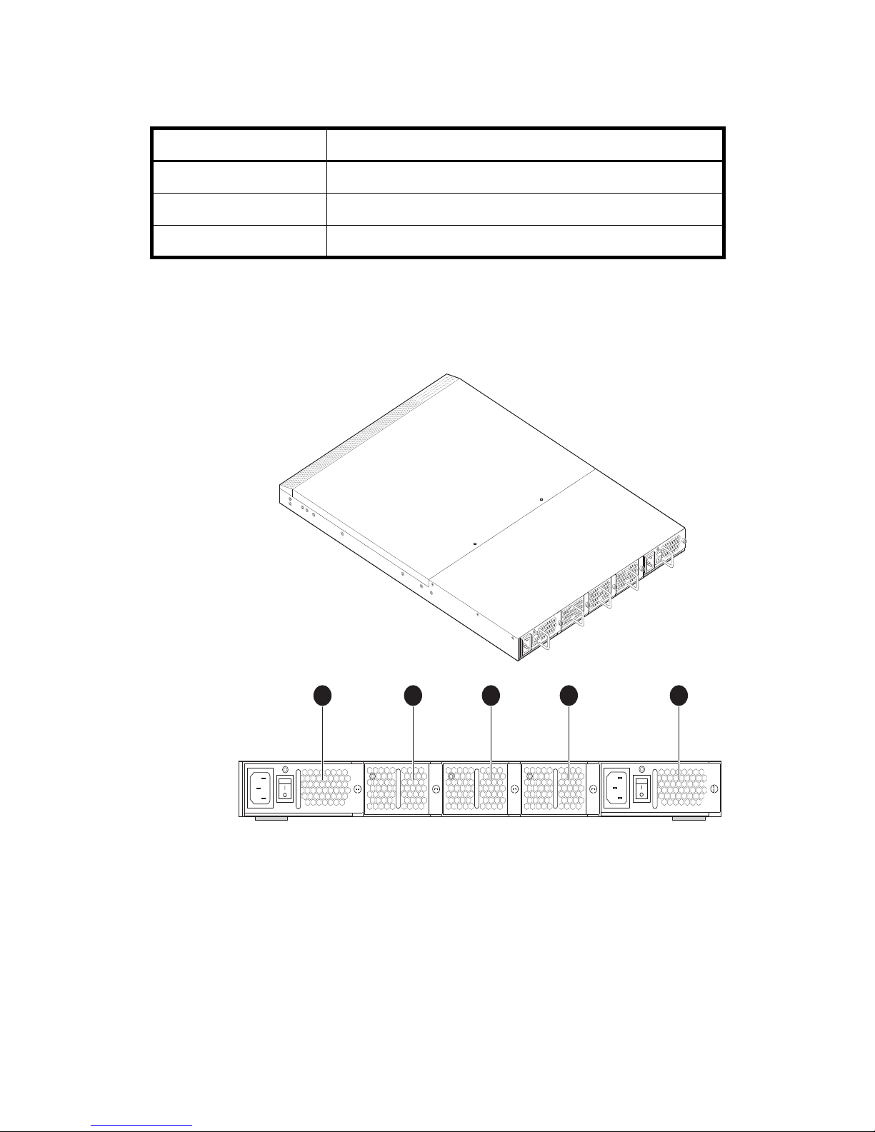
Table 3 SAN Switch 4/32 port side components (continued)
Number Description
5 FC Ports (8-15)
6 FC Ports (16-23)
7 FC Ports (24-31)
SAN Switch 4/32—nonport side
Figure 4 shows the nonport side of the SAN Switch 4/32, which contains the power supplies
(including the AC power inlet, and AC power switch) and fans.
Scale: 1/8" = 1"
Figure 4 SAN Switch 4/32—nonport side
3 4 521
MRO25010a
23SAN Switch 2/8V, 2/16V, 2/16N and 4/32 installation guide
Page 24
Table 4 lists the SAN Switch 4/32 nonport side components.
Table 4 SAN Switch 4/32 nonport side components
Number Description
1 Power supply 2
2 Fan 3
3 Fan 2
4 Fan 1
5 Power supply 1
Upgrading SAN Switch 4/32 ports
The SAN Switch 4/32 is available with either sixteen ports, 0 through 15 (Base model) or
thirty two, ports 16 through 32 (Full model) activated.
To activate additional ports, contact your HP representative to purchase the
8-Port Upgrade License
with sixteen active ports, purchase one 8-Port Upgrade License to activate ports 16 through 23.
Purchase two 8-Port Upgrade Licenses to activate ports 24 through 32.
NOTE: Check port status to verify if the license is pre-installed. For example, use the
portshow command for ports 16 through 32. If the port status output indicates “Started” and
“Licensed”, then all thirty two ports are activated.
1. If ports 16 through 32 show no License, purchase the
License,
Your HP representative requires the SAN Switch 4/32’s World Wide Number (WWN) in
order to assign a license key. Enter the switchshow command to obtain the WWN of
your SAN Switch 4/32.
2. Install the
approximately sixteen uppercase and lowercase letters and digits.
a. Log in to the SAN Switch 4/32 as admin.
b. Enter the licenseadd command, followed by the license key enclosed in quotation
Part Number T3677A, from an authorized HP representative.
HP StorageWorks 8-Port Upgrade License
marks.
, Part Number T3677A. For example, if your SAN Switch 4/32 shipped
HP StorageWorks 8-Port Upgrade
. The license key is a string of
HP StorageWorks
Overview24
Page 25

NOTE: Enter the license key exactly as issued. If you enter it incorrectly, the license will not
function properly.
c. After entering the license key, use the licenseshow command to check to see if it is
valid.
If a licensed product is not displayed, the license is invalid.
NOTE: After you enter a license, the licensed product is available immediately; the system
does not require a reboot.
3. Next, configure the inactive ports. Use the portstart command to start the ports. (This
command loads the port code, unlike the portenable command, which enables the port
laser.) For example:
portstart 16-32
4. Use the portenable command to enable the ports. For example:
portenable 16-32
5. Optionally, use the portshow command to verify that the newly activated ports are
“Started.”
SAN Switch licensing
SAN Switches operate differently in the network depending on the HP StorageWorks domain
licenses installed as follows:
• 2-domain Fabric License—Allows a maximum of two switches to operate within a
domain. The SAN Switch 2/8V and SAN Switch 2/16V ship with this license installed.
• 4-domain Fabric License—Upgrades the current 2-domain Fabric License, allowing a
maximum of four switches to operate within a domain. This license is offered for the SAN
Switch 2/8V and SAN Switch 2/16V models only
• Full-fabric License—Allows four or more switches to operate within a domain. All SAN
Switch Power Pack models ship with this license installed.
To determine the type of licensing installed on your SAN Switch, enter the licenseshow
command at the CLI prompt. A list of the all licenses currently installed on the switch displays,
as shown in the following example.
25SAN Switch 2/8V, 2/16V, 2/16N and 4/32 installation guide
Page 26
Example
switch:admin> licenseshow
AbbbcDefcQxdezdr:
Web license
Zoning license
Fabric license
Remote Switch license
Extended Fabric license
Fabric Watch license
Performance Monitor license
Trunking license
Security license
switch:admin>
NOTE: If the licensed feature is listed, the feature is installed and immediately available.
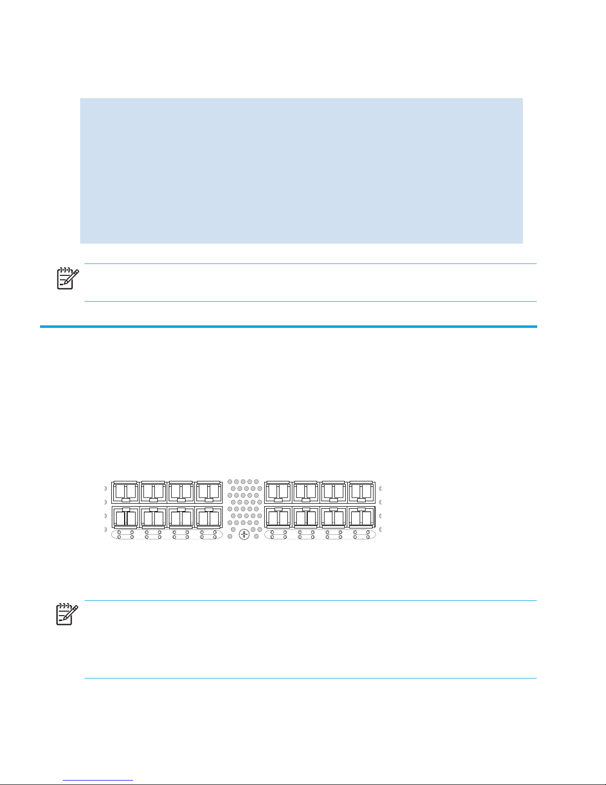
ISL Trunking groups
If your SAN Switch is licensed for ISL trunking, use the trunking groups available on the switch.
The Fibre Channel ports are numbered from left to right, color-coded into groups of four to
indicate the groups of ports that can be used in the same interswitch link (ISL) trunking group.
The trunking groups are the two or four sets of four ports at the top or at the bottom of the
group, as shown in Figure 5.
0
1
4
5
3
2
7
6
8
9
12
13
11
10
15
14
Figure 5 Trunking groups
NOTE: ISL Trunking is optional HP StorageWorks software that allows you to create trunking
groups of ISLs between adjacent switches. For more information, see the “ISL Trunking” chapter
in the
HP StorageWorks features overview
, located on the Software CD that shipped with your
switch.
Overview26
Page 27

SAN Switch supported (optional) features
SAN Switches support the following optional software, activated with the purchase of a
corresponding license key.
• ISL Trunking
• Fabric Watch
• Advanced Performance Monitoring
• Extended Fabrics
• Remote Switch
NOTE: All SAN Switch Power Pack models ship with these licensed options already enabled.
Refer to the
detailed information on these features. All supporting Fabric OS documentation resides on the
Software CD that shipped with your switch.
HP StorageWorks features overview
for the firmware version that you are running for
27SAN Switch 2/8V, 2/16V, 2/16N and 4/32 installation guide
Page 28

SAN Switch optional kits
Table 5 lists the optional hardware kits.
Table 5 Optional kits
Option Part Number
HP StorageWorks 4Gb SW 4PK SFP
Transceiver
HP StorageWorks 4Gb SW SnglePK SFP
Transceiver
Short wavelength SFP A6515A* or 300834-B21**
Long wavelength SFP, 10 km A6516A* or 300835-B21**
Long wavelength SFP, 35 km 300836-B21**
2m LC-to-LC Fibre Channel (fc) cable C7524A*
2m LC-to-LC multi-mode fc cable 221692-B21**
16m LC-to-LC fc cable C7525A*
5m LC-to-LC multi-mode fc cable 221692-B22**
50m LC-to-LC fc cable C7526A*
15m LC-to-LC multi-mode fc cable 221692-B23**
200m LC-to-LC fc cable C7527A*
A7448A
A7446A
30m LC-to-LC multi-mode fc cable 221692-B26**
50m LC-to-LC multi-mode fc cable 221692-B27**
2m LC-to-SC fc cable C7529A*
2m LC-to-SC multi-mode fc cable 221691-B21**
16m LC-to-SC fc cable C7530A*
5m LC-to-SC multi-mode fc cable 221691-B21**
15m LC-to-SC multi-mode fc cable 221691-B23**
30m LC-to-SC multi-mode fc cable 221691-B26**
50m LC-to-SC multi-mode fc cable 221691-B27**
Overview28
Page 29

Table 5 Optional kits (continued)
Option Part Number
SC female to SC female adapter C7534A*
2m LC male to SC male adapter kit C7540A*
* premerger HP part number
** premerger Compaq part number
NOTE: To obtain the latest information on hardware and software components, go to
http://www.hp.com
.
29SAN Switch 2/8V, 2/16V, 2/16N and 4/32 installation guide
Page 30

Overview30
Page 31

2 Installing and configuring
This chapter provides the following information:
• SAN Switch shipping carton contents, page 32
• Installation and safety considerations, page 34
• Installing as a stand-alone device, page 36
• Installing the switch in a rack using the SAN Switch Rack Mount Kit, page 37
• Cabling and configuring the SAN Switch, page 50
• Connecting the SAN Switch to the fabric, page 51
31SAN Switch 2/8V, 2/16V, 2/16N and 4/32 installation guide
Page 32

SAN Switch shipping carton contents
Figure 6 shows the shipping carton contents for the SAN Switch 4/32 specifically. The items
shown here ship with all SAN Switch models. See Table 6 for a complete description.
1
3
MRO25011a
Figure 6 SAN Switch shipping carton contents
SAN Switch shipping carton contents checklist
Table 6 identifies the carton contents included with your SAN Switch 2/8V, 2/16V, 2/16N or
4/32.
2
Installing and configuring32
Page 33

Table 6 SAN Switch shipping carton contents checklist
Item Number Description
1
One SAN Switch Accessories Box containing:
• One 10 ft. (3.0 m.) RS-232 serial cable; convertable to
an RJ-45 connector by removing the adapter on the
end of the cable
• One SAN Switch Rack Mount Kit hardware pouch:
• (10) #8-32 x 3/16-inch Phillips pan-head screws
with thread lock for the SAN Switch 4/32 only
• (14) #8-32 x 5/16-inch pan-head SEMS screws
for use with the SAN Switch 2/8V, SAN Switch
2/16V and SAN Switch 2/16N
• (10) #10-32 x 1/2-inch Phillips pan-head screws
with captive star lock washers
• (8) #10 alignment washers
• (8) #10 adapter washers
• (2) 1/4-20 hex nut with captive star lock washers
• (2) 1/4-inch flat washers
• Four Rubber feet for mounting on a flat surface,
(i.e., a laboratory bench).
• One HP StorageWorks SAN Switch Software CD,
One set of HP StorageWorks product documentation
including
2/16V, 2/16N and 4/32 installation guide
HP StorageWorks SAN Switch 2/8V,
(this
guide), Safety Guides, User License and Warranty
• For the SAN Switch 2/8V, one country-specific AC
power cord, and one PDU power cord (not shown).
For the SAN Switch 2/16V, 2/16N and 4/32, two
AC power cords and two PDU power cords (not
shown).
2
SAN Switch Rack Mount Kit rail assemblies:
• (2) rear mounting brackets
• A right inner rail and a right outer rail
• A left inner rail and a left outer rail
3
One HP StorageWorks SAN Switch 2/8V, SAN Switch 2/16V,
SAN Switch 2/16N or SAN Switch 4/32
33SAN Switch 2/8V, 2/16V, 2/16N and 4/32 installation guide
Page 34

Installation and safety considerations
You can install the switch using one of the following methods:
• As a stand-alone unit on a flat surface. See Installing as a stand-alone device, page 36.
• HP highly recommends mounting the switch in one of the following HP customized racks:
•HP StorageWorks System/e Rack
• HP StorageWorks 10,000 Series Rack
See Installing the switch in a rack using the SAN Switch Rack Mount Kit, page 37 for
detailed instructions.
Electrical considerations
For successful installation and operation of the switch, ensure that the following electrical
requirements are met. For power supply information, refer to ”SAN Switch technical
specifications” on page 99.
• Primary AC input 100-240 VAC (switch auto-senses input voltage),
47-63 Hz.
• Correctly wired primary outlet, with circuit protected by a circuit breaker and grounded in
accordance with local electrical codes.
• Adequate supply circuit, line fusing, and wire size, as specified by the electrical rating on
the switch nameplate.
Environmental considerations
Verify that the following environmental considerations are met:
• At a minimum, adequate cooling requires that you install the switch with the non-port side,
which contains the air intake vents, facing the cool-air aisle.
• Verify that a minimum of 24 cubic ft./minute of air flow is available to the air intake vents
on the nonport side of the switch.
• Verify that the ambient air temperature does not exceed 40° C (104° F) while the switch is
operating.
Installing and configuring34
Page 35

Rack specifications
If installing the switch in a rack:
• Plan a rack space that is 1 rack unit (1.75 inches; 4.45 cm) high, 19 inches (48.3 cm)
wide, and at least 30 inches (76.2 cm) deep.
• The rack should be balanced and the installed equipment should be within the rack’s
weight limits. Ensure the rack is mechanically secured to insure stability in the event of
an earthquake.
• Ground all equipment in rack through a reliable branch circuit connection and maintain
ground at all times. Do not rely on a secondary connection to a branch circuit, such as
a power strip.
• Ensure that airflow and temperature requirements are met on an ongoing basis,
particularly if the switch is installed in a closed or multi-rack assembly.
• Verify that the additional weight of the switch does not exceed the rack’s weight limits or
unbalance the rack in any way.
• Secure the rack to ensure stability in case of unexpected movement, such as an
earthquake.
Cooling considerations
Cooling air is drawn into the switch chassis by the fans mounted on the rear of the chassis. The
air is expelled through vents in the front (port side) of the chassis. HP recommends installing the
switch so that air intake and exhaust for all components in the rack are flowing in the same
front-to-back direction.
Follow these guidelines to ensure proper air flow, and prevent component overheating:
• To ensure adequate cooling, install the switch with the non-port side, which contains the air
intake vents, facing the cool-air aisle.
• Verify a minimum of 47 cubic feet/minute (79.8 cubic meters/hour) of air flow is available
to the air intake vents on the non-port side of the switch.
• Verify that the ambient air temperature does not exceed 40° Celsius (104° Fahrenheit)
while the switch is operating.
CAUTION: Do not block air vents. The switch uses ambient air for cooling.
35SAN Switch 2/8V, 2/16V, 2/16N and 4/32 installation guide
Page 36

Installing as a stand-alone device
Follow these steps to install as a stand-alone unit.
1. Unpack the switch and verify that all items listed on ”SAN Switch shipping carton contents”
on page 32 are present and undamaged.
2. Locate the four rubber feet in the Accessory box.
3. Apply the adhesive rubber feet. Applying the rubber feet in the switch helps prevent the
switch from sliding off the supporting surface.
a. Clean the indentations at each corner of the bottom of the switch to ensure that they are
free of dust or other debris that might lessen the adhesion of the feet.
b. With the adhesive side against the chassis, place one rubber foot in each indentation
and press into place.
4. Place the switch on a flat, sturdy surface.
5. Apply power to the switch as described in ”Powering on and off” on page 62.
CAUTION: Do not connect the switch to the network until the IP address is correctly set. For
instructions on how to set the IP address, see ”Cabling and configuring the SAN Switch” on
page 50.
Installing and configuring36
Page 37

Installing the switch in a rack using the SAN
Switch Rack Mount Kit
This section provides instructions for installing the SAN Switch in an HP System/e rack, or in an
HP 10,000 series rack using the HP StorageWorks SAN Switch Rack Mount Kit supplied with
your switch.
Install the SAN Switch Rack Mount Kit in one of two ways:
• Allow the port side of the switch to slide out of the exhaust-air side of the rack.
• In this installation, the port side of the switch is flush with the edge of the rack.
• Allow the nonport side of the switch to slide out the cool-air side of the rack.
• In this installation, the port side of the switch is set 3 in. (7.62 cm.) back from the edge
of the rack, allowing a more gradual bend in the fiber optic cables.
NOTE: The SAN Switch Rack Mount Kit install requires one technician.
The following items are required to install the switch in a rack:
• SAN Switch
• Power cables
• #2 Phillips screwdriver
• 7/16-inch wrench or socket
• SAN Switch Rack Mount Kit hardware, illustrated in Table 7
37SAN Switch 2/8V, 2/16V, 2/16N and 4/32 installation guide
Page 38

Table 7 identifies SAN Switch Rack Mount Kit rails and rail mounting hardware.
Table 7 SAN Switch Rack Mount Kit hardware
Item Description
(2) rear mounting brackets
A right inner rail and a right outer rail
A left inner rail and a left outer rail
(10) #8-32 x 3/16-inch Phillips pan-head screws with
thread lock, for use with the SAN Switch 4/32.
(14) #8-32 x 5/16-inch Phillips pan-head SEMS screws for
use with the SAN Switch 2/8V, SAN Switch 2/16V, SAN
Switch 2/16N.
(10) #10-32 x 1/2-inch Phillips pan-head screws with
captive star lock washer
(8) #10 alignment washers
Installing and configuring38
Page 39
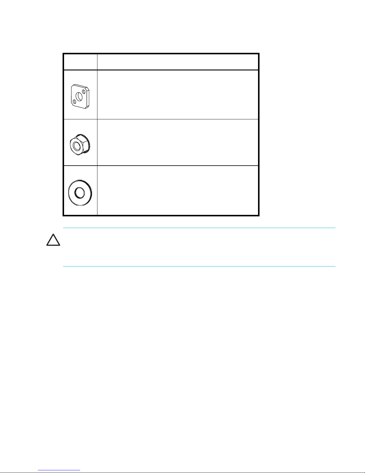
Table 7 SAN Switch Rack Mount Kit hardware (continued)
Item Description
(8) #10 adapter washers
(2) 1/4-20 hex nuts with captive star lock washer
(2) 1/4-inch flat washers
CAUTION: For proper air flow, the SFP media side of the SAN Switch must face the rear of
the rack. This mounting allows air to enter from the front of the rack and to exhaust at the rear
of the rack, similar to the other rack-mounted equipment.
To install the switch in a rack:
1. Check contents of the shipping carton to verify all the required parts and hardware are
available.
2. Choose a mounting location in the rack for the switch.
3. Attach the rear mounting brackets to the rear rack uprights by completing one of the steps
listed on page 40 or page 41.
39SAN Switch 2/8V, 2/16V, 2/16N and 4/32 installation guide
Page 40

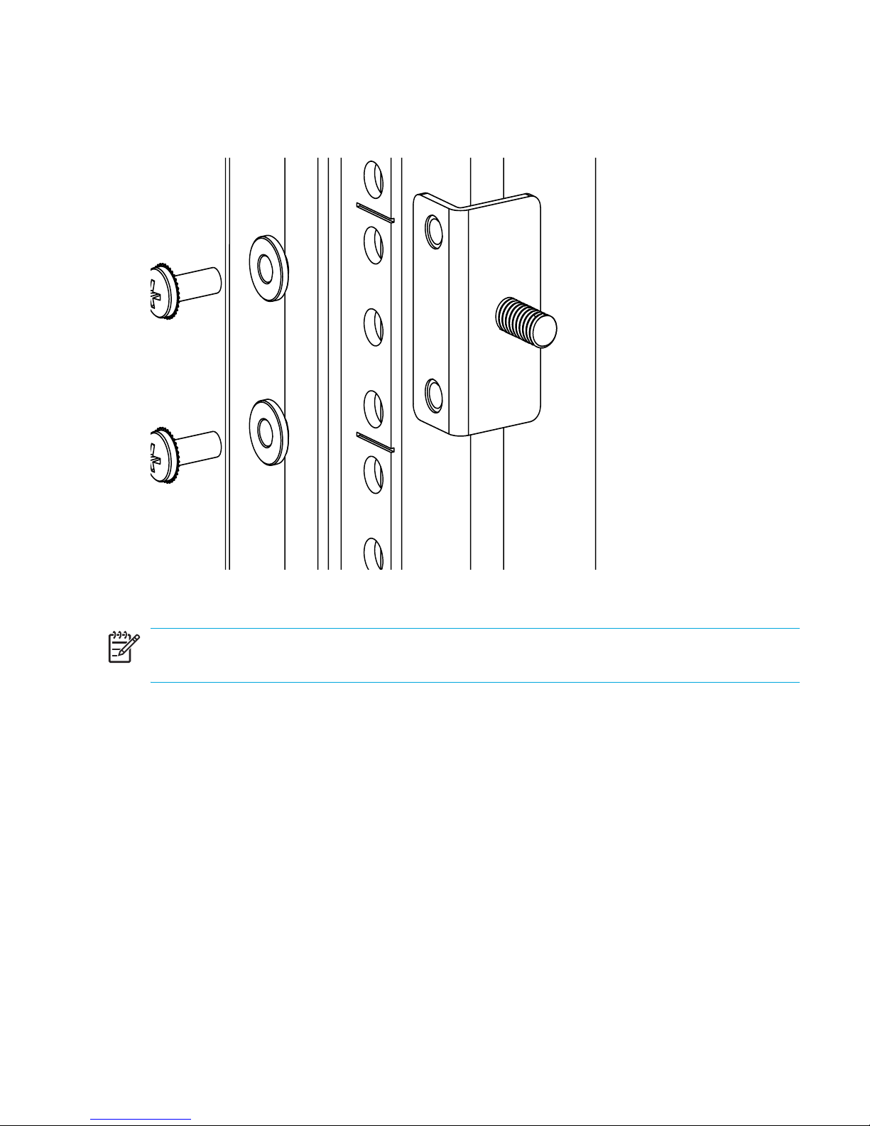
• For an HP 10,000 series, assemble each of the two brackets with (2) #10-32 x 1/2-inch
Phillips pan-head screws with captive star lock washers and (2) #10 adapter washers as
shown in Figure 7.
Figure 7 Installing the rear mounting brackets (HP 10,000 series)
Installing and configuring40
Page 41
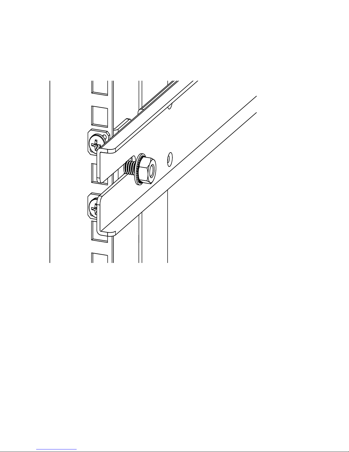
• For an HP System/e rack, install each of the two rear mounting brackets with (2) #10-32 x
1/2-inch Phillips pan-head screws and (2) #10 alignment washers as shown in Figure 8.
Figure 8 Installing the rear mounting brackets (HP System/e rack-left rear upright)
NOTE: This kit contains both left rails and right rails. The rails are marked Right and Left.
41SAN Switch 2/8V, 2/16V, 2/16N and 4/32 installation guide
Page 42
4. Assemble the outer rails by completing the appropriate step page 42 or page 43:
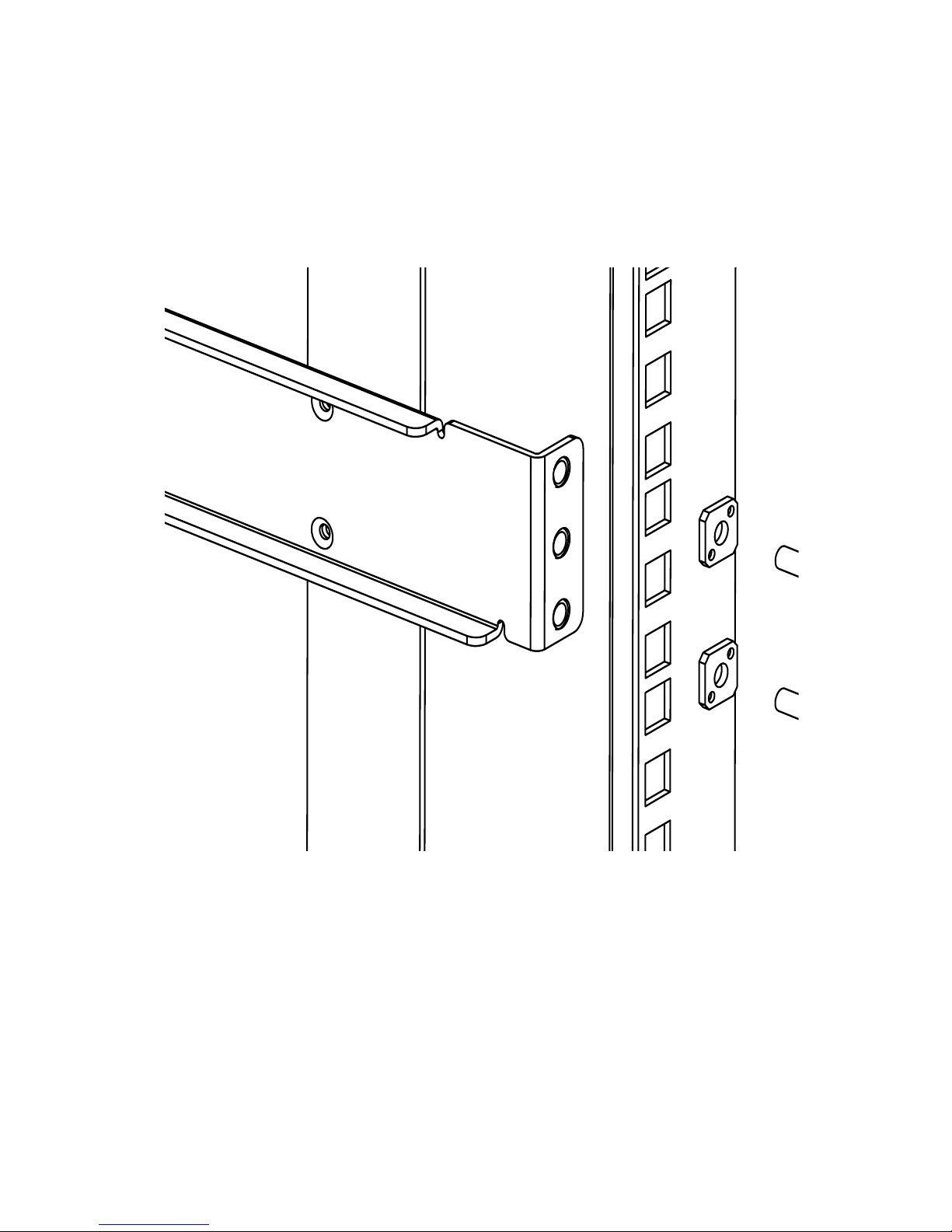
a. Attach the left outer rail and the right outer rails to the rear mounting brackets using
(2) 1/4-20 hex nuts with captive star lock washers attached loosely as shown in
Figure 9. Don’t tighten them. The nuts will be tightened later in step 12 on page 49.
Figure 9 Installing the outer rails (HP 10,000 series)
Installing and configuring42
Page 43
b. Depending on the rack you are using, complete one of the following tasks:
• For an HP 10,000 series, install two #10-32 x 1/2-inch Phillips pan-head screws
with captive star lock washers and two #10 adapter washers in the upper and
lower hole locations of the right rail. Then install two #10-32 x 1/2-inch Phillips
pan-head screws with captive star lock washers and two #10 adapter washers in
the upper and lower hole locations of the left rail. See Figure 10.
Figure 10 Assembling the outer rails (HP 10,000 series)
43SAN Switch 2/8V, 2/16V, 2/16N and 4/32 installation guide
Page 44

• For an HP System/e rack, install two #10-32 x 1/2-inch Phillips pan-head screws
with captive star lock washers and two #10 alignment washers in the upper and
lower hole locations of the right rail. Then install two #10-32 x 1/2-inch Phillips
pan-head screws with captive star lock washers and two #10 alignment washers in
the upper and lower hole locations of the left rail. See Figure 11.
Figure 11 Assembling the outer rails (HP System/e rack)
5. The SAN Switch Rack Mount Kit provides different screw types for securing the inner rails.
Specific switches require a different number of these screws. See Table 8 to determine the
appropriate number of screws.
CAUTION: Do not use any screws other than the ones provided. Use of any longer lengths
can cause damage to internal components.
Installing and configuring44
Page 45
Table 8 Number of screws required to assemble the inner rails
Switch #8-32 x 5/16-inch screws #8-32 x 3/16-inch screws
SAN Switch 2/8V 10 Not Applicable
SAN Switch 2/16V,
10 Not Applicable
SAN Switch 2/16N
SAN Switch 4/32 Not Applicable 10
6. Identify the screw holes on the inner rails for your specific switch. The screw holes are
labelled as follows:
a. To attach the inner rails to the SAN Switch 2/8V, SAN Switch 2/16V or
SAN Switch 2/16N use the screw holes marked 8.
b. To attach the inner rails to the SAN Switch 4/32 use the screw holes marked 16.
NOTE: The mounting holes in the inner rails are marked 32, 16, and 8. For the SAN Switch
2/8V, SAN Switch 2/16V or SAN Switch 2/16N use the screw holes labelled 8. For the SAN
Switch 4/32, use the mounting holes labelled 16.
7. Secure the two inner rails (one on each side) of the switch using the appropriate number of
screws (refer to Table 8) as follows:
• For the SAN Switch 2/8V, secure each inner rail (one on each side) to the switch using
five #8-32 x 5/16-inch Phillips pan-head SEMS screws as shown in Figure 12.
• For the SAN Switch 2/16V or 2/16N, secure each inner rail (one on each side) to the
switch using five #8-32 x 5/16-inch Phillips pan-head SEMS screws, see Figure 13.
• For the SAN Switch 4/32, secure each inner rail (one on each side) to the switch using
five #8-32 x 3/16-inch Phillips pan-head screws with thread lock as shown in
Figure 14.
NOTE: For factory integration only, tighten the #8-32 x 5/16-inch Phillips pan-head SEMS
screws and torque between 6 to 8 inch-pounds.
45SAN Switch 2/8V, 2/16V, 2/16N and 4/32 installation guide
Page 46
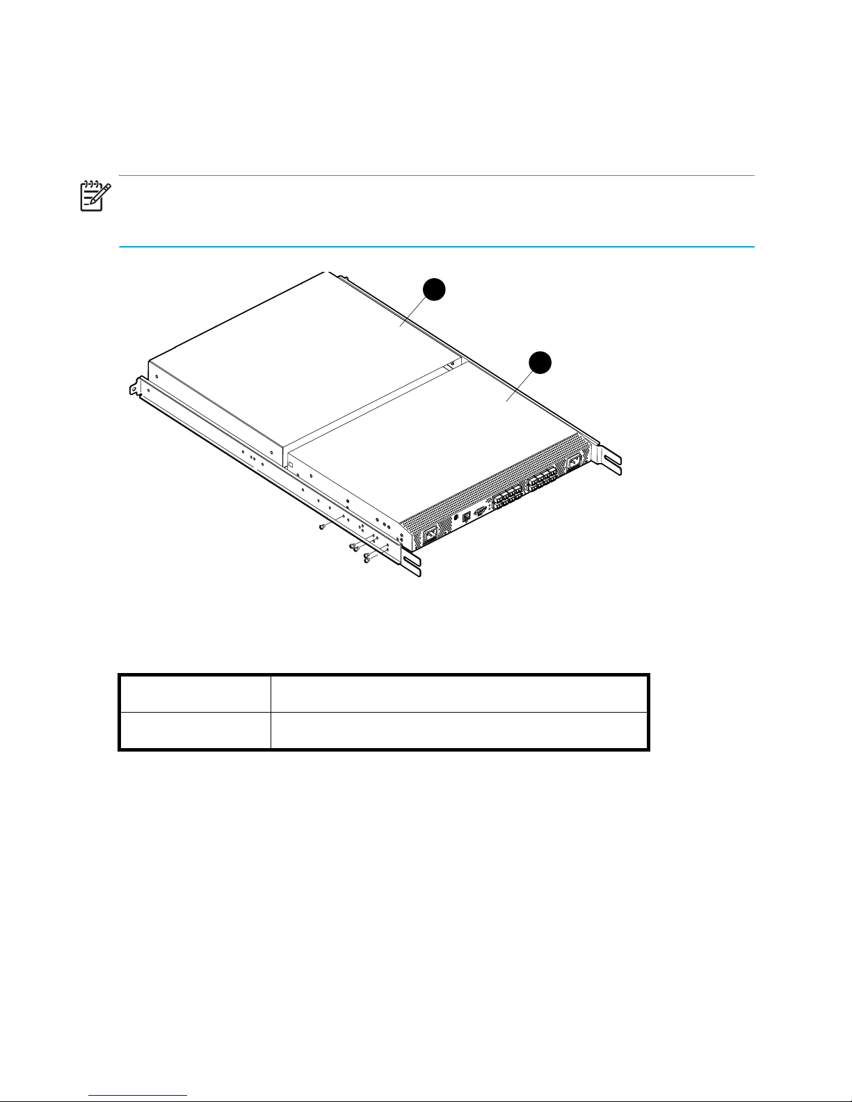
8. Verify that a plenum is installed on the SAN Switch 2/8V, SAN Switch 2/16V or SAN
Switch 2/16N models only, as shown in Figure 12. The plenum is an overlay that
dissipates the heat generated by the switch, preventing overheating.
NOTE: The plenum is a required part of this installation for SAN Switch 2/8V, SAN Switch
2/16V or 2/16N models only, when installed in HP 10,000 series, or System/e racks.
1
2
0013a
Figure 12 Securing the inner rails to the SAN Switch 2/8V with plenum
The components in Table 12 include:
1
Plenum
2 Switch
Installing and configuring46
Page 47
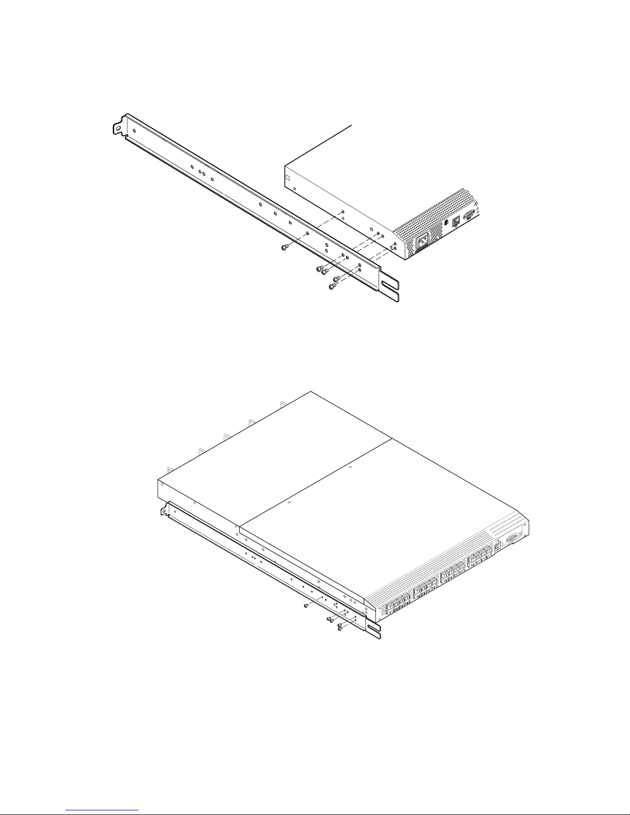
9. Contact your authorized HP switch reseller for information if a plenum is not preinstalled on
your SAN Switch 2/8V, SAN Switch 2/16V or SAN Switch 2/16N model only.
0012a
Figure 13 Securing the inner rails to the SAN Switch 2/16V
Figure 14 Securing the inner rails to the SAN Switch 4/32
!
IOIOI
L
N
K
S
P
D
MRO25018a
47SAN Switch 2/8V, 2/16V, 2/16N and 4/32 installation guide
Page 48

10.Insert the switch with the attached inner rails into the outer rails. Please note this step (#10),
applies to both the HP 10,000 series and System/e racks.
NOTE: Note that the SAN Switch mounts in the rack with its front, the port side, facing the
back of the rack. The rear of the switch, the AC side, faces the front of the rack.
Figure 15 Installing the switch into a rack (HP 10,000 series rack)
Installing and configuring48
Page 49

11.Insert the switch into the rack and install (2) #10-32 x 1/2-inch Phillips pan-head screws
with captive star lock washers with one on each side. See Figure 15 and Figure 16.
Figure 16 Installing the switch into a rack (HP System/e rack)
12.Tighten the nuts installed in step 4 on page 42. See Figure 9 on page 42.
NOTE: To uninstall a switch, remove the middle #10-32 x 1/2-inch Phillips pan head screw
with captive star lock washer from either side of the rack uprights.
49SAN Switch 2/8V, 2/16V, 2/16N and 4/32 installation guide
Page 50

Cabling and configuring the SAN Switch
The SAN Switch must be configured to ensure correct operation within a network and fabric.
For instructions about configuring the switch to operate in a fabric containing switches from
other vendors, refer to the
running on your switch. For more information about the commands used in this procedure, refer
to the
switch.
NOTE: All supporting Fabric OS documentation resides on the Software CD that shipped with
your switch.
HP StorageWorks command reference guide
Recommendations for cable management
Following is a list of HP recommendations for cable management:
• Plan for rack space required for cable management before installing the switch.
• The minimum bend radius for a 50 micron cable is 2 inches under full tensile load and 1.2
inches with no tensile load.
HP StorageWorks procedures user guide
for the Fabric OS version running on your
for the Fabric OS version
• Leave at least 3.28 ft. (1 m.) of slack for each port cable. This provides room to remove and
replace the switch, allows for inadvertent movement of the rack, and helps prevent the
cables from being bent to less than the minimum bend radius.
• If you are using ISL Trunking, consider grouping cables by trunking groups. The cables used
in trunking groups must meet specific requirements, as described in the
features overview
• For easier maintenance, label the fiber optic cables and record the devices to which they
are connected.
• Keep LEDs visible by routing port cables and other cables away from the LEDs.
• Do not use tie wraps on fiber optic cables, because the wraps are easily overtightened and
can damage the optic fibers. HP recommends using Filcrow wraps.
, located on the Software CD that shipped with your switch.
HP StorageWorks
Installing and configuring50
Page 51

Connecting the SAN Switch to the fabric
Follow the sequence listed next. Procedures are included in the following sections:
1. Making a serial connection, page 51
2. Logging in, page 53
3. Setting the IP address, page 54
4. Creating an Ethernet connection, page 55
5. Modifying the Fibre Channel domain ID (Optional), page 56
6. Installing the SFP transceivers, page 57
7. Connecting the cables, page 57
8. Verifying the configuration, page 58
Items required
Obtain the following items to configure the SAN Switch for use in a network:
• SAN Switch 2/8V, SAN Switch 2/16N, SAN Switch 2/16V or SAN Switch 4/32 installed
and connected to a power source
• Workstation with an installed terminal emulator, such as HyperTerminal
• Unused IP address and corresponding subnet mask and gateway address
• Serial cable (supplied with switch)
• Ethernet cable
• SFP transceivers and compatible cables, as required
• Access to an FTP server for backing up the switch configuration
Making a serial connection
Use these steps to make a serial connection via the SAN Switch serial port.
1. Insert the serial cable into the serial port on the switch.
2. Connect the serial cable to an RS-232 serial port on the workstation as shown in Figure 17.
51SAN Switch 2/8V, 2/16V, 2/16N and 4/32 installation guide
Page 52

NOTE: Figure 17 shows the SAN Switch 2/16V. This procedure is the same for all SAN
IOIOI
100-240
C 1.0A 47-63Hz
100-240
C 1.0A 47-63Hz
Switches.
1
0
0
2
4
0
VAC
1
.
0
A
4
7
-6
3
H
z
IOIOI
!
1
0
0
2
4
0
VAC
1
.0
A
4
7
6
3
H
z
0014a
Figure 17 Connecting the serial cable to a SAN Switch 2/16V
NOTE: If the serial port on the workstation uses an RJ-45 connector instead of an RS-232,
remove the adapter on the end of the serial cable and insert the exposed RJ-45 connector into
the RJ-45 serial port on the workstation.
3. Disable any serial communication programs running on the workstation.
4. Open a terminal emulator application (such as HyperTerminal on a PC or TERM in a UNIX
environment) and configure the application as follows:
• In a Windows 95, 98, 2000, or NT environment:
Bits per
9600
second
Databits 8
Parity None
Stop bits 1
Flow control None
• In a UNIX environment, type the following string at the prompt:
tip /dev/ttyb -9600
Installing and configuring52
Page 53

Logging in
IOIOI
100-240
C 1.0A 47-63Hz
100-240
C 1.0A 47-63Hz
Once a serial connection is established, apply power to the switch.
1. Connect the power cords to both power supplies and power sources, as shown in
Figure 18.
NOTE: The SAN Switch 2/8V uses one power cord, all other SAN Switches use two.
1
0
0
2
4
0
VAC
1
.0
A
4
7
6
3
H
z
IOIOI
!
1
0
0
-2
4
0
VAC
1
.0
A
4
7
6
3
H
z
0015a
Figure 18 Connecting SAN Switch 2/16V power cords
NOTE: To protect against AC failure, connect the power cords to outlets on separate circuits.
Verify that the cords have a minimum service loop of six inches available at the connection to
the switch and are routed to avoid stress.
2. To power on, set the two AC switches to 1.
NOTE: The SAN Switch 2/8V uses only one power switch.
3. The power supply LED lights up green, and the switch runs POST. The switch requires a
minimum of three minutes to boot and complete POST.
4. After POST and the boot process completes, verify that the System Status and Power Status
LEDs light green.
53SAN Switch 2/8V, 2/16V, 2/16N and 4/32 installation guide
Page 54

5. Using a serial connection, when the terminal emulator application stops reporting
information, press Enter to display the login prompt.
6. Log in using the administrative account; the logon is “admin” and the default password is
“password”. Create up to two simultaneous admin sessions and four user sessions.
For specific details, refer to the specific
StorageWorks command reference guide
supporting Fabric OS documentation resides on the Software CD that shipped with your
switch.
Setting the IP address
Replace the default IP addressing information with the information provided by your network
administrator. By default, the IP address is set to 10.77.77.77.
1. Type ipaddrset at the terminal emulator application prompt.
2. Type remaining IP addressing information, as prompted.
3. Optionally, verify that the address was correctly set by entering the ipaddrshow
command at the prompt.
4. Record the IP address on the label clearly displayed on the port side of the chassis.
For the SAN Switch 4/32 only, record the IP address on the pull out tab provided for this
purpose on the port side of switch.
5. If the serial port is no longer required, log out of the serial console, remove the serial cable,
and replace the safety plug in the serial port.
HP StorageWorks procedures user guide
for the Fabric OS running on your switch. All
and the
HP
NOTE: Notes provide important information to explain a concept or to complete a task
Installing and configuring54
Page 55

Creating an Ethernet connection
100-240
C 1.0A 47-63Hz
100-240
C 1.0A 47-63Hz
Use these steps to create an Ethernet connection.
1. Connect an Ethernet cable to the Ethernet port and to the workstation or to an Ethernet
network containing the workstation as shown in Figure 19.
NOTE: Figure 19 shows the SAN Switch 2/16V. This procedure is the same for all SAN
Switches.
1
0
0
2
4
0
VAC
1
.0
A
4
7
-6
3
H
z
IOIOI
!
1
0
0
2
4
0
VAC
1
.0
A
4
7
-6
3
H
z
0016a
Figure 19 Connecting the Ethernet cable to the SAN Switch 2/16V
Once the Ethernet cable is connected, access the switch remotely, via the CLI or the built-in
Advanced Web Tools GUI software.
2. Log in to the switch by telnet, using the admin account.
55SAN Switch 2/8V, 2/16V, 2/16N and 4/32 installation guide
Page 56

Modifying the Fibre Channel domain ID (Optional)
If desired, you can modify the Fibre Channel domain ID. The default Fibre channel domain ID
is domain 1. If the switch is not powered on until after it is connected to the fabric and the
default Fibre channel domain ID is already in use, the domain ID for the new switch is
automatically reset to a unique value. If the switch is connected to the fabric after is has been
powered on and the default domain ID is already in use, the fabric segments.
The domain IDs that are currently in use can be determined using the fabricshow command.
The number of domains is determined by your domain fabric licensing. See ”SAN Switch
licensing” on page 25.
To modify the domain ID:
1. Type switchdisable to disable the switch.
2. Type configure. This prompts display sequentially; type a new value or press Enter to
accept each default value.
3. At the Fabric Parameters prompt, type Y and press Enter:
Fabric parameters (yes, y, no, n): [no] y
4. Enter a unique domain ID, such as the domain ID used by the previous switch, if still
available:
Domain: (1..239) [1] 3
5. Complete the remaining prompts or press Ctrl+D to accept the remaining default settings.
6. Enter the switchenable command to Re-enable the switch.
7. Optionally, specify any custom status policies:
a. Enter the switchstatuspolicyset command at the prompt. This command sets the
policy parameters that determine the overall switch status.
b. Customize the status policies.
To deactivate the alarm for a particular condition, enter 0 at the prompt for that condition.
Installing and configuring56
Page 57

Installing the SFP transceivers
The SAN Switch does not ship with SFPs. A list of supported SFPs can be found in ”SAN Switch
optional kits” on page 28.
Use the following procedure to install the SFP transceivers into the Fibre Channel ports.
The ports selected for use in trunking groups must meet specific requirements. For a list of these
requirements, refer to the specific “ISL Trunking” chapter in the
overview
Use these steps to install SFP transceivers.
1. Position a transceiver so that it is oriented correctly and insert it into a port until the latching
2. Repeat for the remaining ports, as required.
located on the Software CD that shipped with your switch.
mechanism clicks. The transceivers are keyed to ensure correct orientation. If a transceiver
does not install easily, ensure that it is correctly oriented.
For instructions specific to the type of transceiver, refer to the transceiver manufacturer’s
documentation.
Connecting the cables
HP StorageWorks features
Use these steps connect the cables to the SFP transceivers.
CAUTION: The minimum bend radius for a 50-micron cable is 2 inches under full tensile
load, and 1.2 inches with no tensile load.
Because they are easily overtightened, tie wraps are not recommended for optical cables.
1. The cable connectors are keyed to ensure correct orientation. Orient a cable connector so
that the key (ridge on one side of connector) aligns with the slot in the transceiver and insert
cable into transceiver until latching mechanism clicks. If a cable does not install easily,
ensure it is correctly oriented. For instructions specific to cable type, refer to the cable
manufacturer’s documentation.
2. Repeat for the remaining transceivers, as required.
57SAN Switch 2/8V, 2/16V, 2/16N and 4/32 installation guide
Page 58

Verifying the configuration
Use these steps to confirm that the switch is configured and ready for use.
1. Check LEDs to verify that all components are functional. For information about LED patterns,
refer to ”Interpreting LED activity” on page 64.
2. Enter the switchshow command from the workstation. This command provides
information about the switch and port status.
3. Enter the fabricshow command from the workstation. This command provides general
information about the fabric.
Backing up the configuration
HP recommends regular backups to ensure that a recent configuration is available.
Back up the switch configuration to an FTP server by entering the configupload command
and following the prompts. This command uploads the switch configuration to the server,
making it available for downloading to a replacement switch, if necessary.
Setting the switch date and time
The date and time switch settings are used for logging events. Switch operation does not
depend on the date and time; a switch with an incorrect date and time value still functions
properly.
You can synchronize the local time of the principal or primary Fabric Configuration Server
(FCS) switch to that of an external Network Time Protocol (NTP) server.
Use these steps to set the date and time of a switch
1. Log in to the switch as admin.
2. Type the date command at the CLI prompt using the following syntax:
date “MMDDhhmm[CC]YY”
The values represent the following:
• MM is the month (01-12).
• DD is the date (01-31).
• hh is the hour (00-23).
• mm is minutes (00-59).
• CC is the century (19-20).
• YY is the year (00-99).
Installing and configuring58
Page 59

Year values greater than 69 are interpreted as 1970-1999; year values less than 70 are
interpreted as 2000-2069. The date function does not support Daylight Savings Time or time
zones, so changes will have to be reset manually.
Example
switch:admin> date
Fri May 5 21:50:00 UTC 1989
switch:admin>
switch:admin> date "0624165203"
Tue Jun 24 16:52:30 UTC 2003
switch:admin>
Synchronizing local time with an external source
Use this procedure to synchronize the local time of the principal or primary FCS switch with
that of an external NTP server:
1. Log in as admin.
2. Enter the tsClockServer [
The
ipaddr
variable represents the IP address of the NTP server that the switch can access.
ipaddr
] command
This argument is optional; by default, its value is “LOCL”.
Example
switch:admin> tsclockserver
LOCL
switch:admin> tsclockserver 132.163.135.131
switch:admin>
Correcting the time zone of a switch
Use these steps set the time zone:
1. Log in as admin.
2. Enter the tsTimeZone command as follows:
tstimezone [houroffset [, minuteoffset]]
• For Pacific Standard Time, enter tsTimeZone -8,0
• For Central Standard Time, enter tsTimeZone -6,0
• For Eastern Standard Time, enter tsTimeZone -5,0
The default time zone for switches is Universal Time Conversion (UTC), which is eight hours
ahead of Pacific Standard Time. The parameters listed do not apply if the time zone of the
switch(es) has already been changed from the default (eight hours ahead of PT).
59SAN Switch 2/8V, 2/16V, 2/16N and 4/32 installation guide
Page 60

Refer to the tsTimeZone command in the
HP StorageWorks command reference guide
for more
detailed information about the command parameters. All supporting Fabric OS documentation
resides on the Software CD that shipped with your switch.
3. Repeat Steps 1 and 2 on all switches for which the time zone needs to be set.
This needs to be done only once, because the value is stored in nonvolatile memory.
For U.S. time zones, see Table 9 to determine the correct parameter for the tsTimeZone
command.
Table 9 tsTimeZone command parameter selection
Local Time tsTimeZone parameter
Atlantic Standard -4,0
Atlantic Daylight -3,0
Eastern Standard -5,0
Eastern Daylight -4,0
Central Standard -6,0
Central Daylight -5,0
Mountain Standard -7,0
Mountain Daylight -6,0
Pacific Standard -8,0
Pacific Daylight -7,0
Alaskan Standard -9,0
Alaskan Daylight -8,0
Hawaiian Standard -10,0
Installing and configuring60
Page 61

3 Managing SAN switches
Once your SAN Switch is installed and configured, you can monitor the health of the switch
and fabric.
This chapter provides the following information:
• Powering on and off, page 62
• Management features, page 63
• Interpreting LED activity, page 64
• Managing SAN Switches from a single management station, page 64
• SAN Switch 2/8V, 2/16V and 2/16N LEDs, page 65
• SAN Switch 2/8V, 2/16V and 2/16N LED patterns, page 67
• SAN Switch 4/32 LEDs—port side, page 70
• SAN Switch 4/32 LEDs—nonport side, page 74
• POST and boot specifications, page 76
• Interpreting POST results, page 77
• Diagnostic tests, page 77
61SAN Switch 2/8V, 2/16V, 2/16N and 4/32 installation guide
Page 62

Powering on and off
Read the following sections to power on and off SAN Switches.
SAN Switch 2/8V
Connect one end of the power cord to the AC inlet on the switch, and the remaining end to a
power source.
To power on, set the AC power switch to I. The switch runs POST by default each time it is
powered on, reset, or rebooted. POST requires approximately 3 minutes.
To power off, set the AC power switch to O and remove the power cord from the power source.
NOTE: Removing all power from the switch triggers a system reset. All devices are returned to
their initial state the next time the switch is powered on.
SAN Switch 2/16V, 2/16N and 4/32
Connect one or both power cords to the AC power inlets on the nonport side of the switch, and
the remaining end to a power source.
To power on, set both AC power switches to I. Power is supplied to the switch as soon as the
first power supply is connected and powered on.
To power off, set the AC power switch to O and remove the AC power cord from the power
source.
NOTE: Removing all power from the switch triggers a system reset. All devices are returned to
their initial state the next time the switch is powered on.
Managing SAN switches62
Page 63

Management features
SAN Switches use built-in management tools to help you monitor fabric topology, check port
status, and debug the switch. Table 10 lists the management applications available.
NOTE: When running IP over Fibre Channel, these management tools must be supported by
both HBA and HBA drivers. For a list of supported HBAs, refer to the
HP StorageWorks SAN design guide
http://h18000.www1.hp.com/products/storageworks/san/documentation.html
Table 10 Management options
:
.
Management tool Out-of-band
support
CLI
Up to two admin sessions and four user sessions simultaneously.
Advanced Web Tools
For information, refer to the HP StorageWorks advanced web tools
user guide for the Fabric OS version running on your switch.
Standard SNMP applications
For information, refer to the HP StorageWorks mib reference guide for
the Fabric OS version running on your switch.
Management Server Ethernet
Ethernet or
serial
connection
Ethernet
connection
Ethernet
connection
connection
In-band
support
IP over Fibre
Channel
IP over Fibre
Channel
IP over Fibre
Channel
Native in-band
interface
(over HBA
only)
63SAN Switch 2/8V, 2/16V, 2/16N and 4/32 installation guide
Page 64

Managing SAN Switches from a single
management station
A management station connected to one switch via Ethernet can also be used to manage other
switches connected to the first switch via Fibre Channel. To do so, set the fibre channel gateway
address of each of the other switches to be managed, to the Fibre Channel IP address of the
first switch. The gateway address of the first switch should be set to what ever the gateway
address is for the subnet that the first switch resides on.
For example:
Management Station First Switch Second Switch Third Switch
Ethernet 192.168.1.09 192.168.1.10 204.1.1.11 204.1.1.12
FCIP 192.168.65.09 192.168.65.10 192.168.65.11 192.168.65.12
Gateway 192.168.1.10 any not self 192.168.1.10 192.168.1.10
The disadvantage of this method is that the management station can only address the
switches.
Interpreting LED activity
System activity and status can be determined through the activity of the LEDs on the switch.
There are three possible LED states that display either green or amber:
• no light
• a steady light
• a flashing light
The LEDs flash during boot, POST, or other diagnostic tests. This is normal and does not
indicate a problem. A healthy state is indicated by a steady green light.
Managing SAN switches64
Page 65

SAN Switch 2/8V, 2/16V and 2/16N LEDs
The five LEDs include Switch Status, Power, Port Status, Port Speed and Ethernet.
Figure 20 shows the port side of the SAN Switch 2/8V. Figure 21 shows the port side of the
SAN Switch 2/16V and 2/16N.
!
100-240 VAC 1.5A 47-63Hz
IOIOI
0
4
152
3
7
6
0017a
1 2
3
Figure 20 SAN Switch 2/8V LED locations
Table 11 identifies LED locations.
Table 11 SAN Switch 2/8V LED Locations
Component Description
1 Ethernet LEDs
2 System and power LEDs
3 Port LEDs
65SAN Switch 2/8V, 2/16V, 2/16N and 4/32 installation guide
Page 66
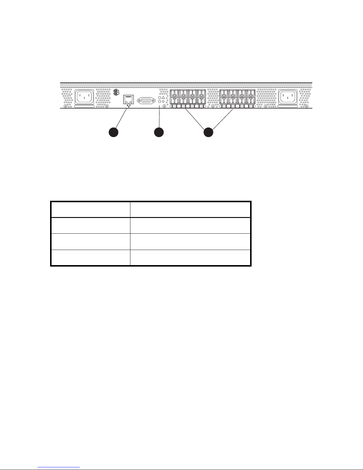
All LEDs reside on the port side of the switch. Figure 21 shows the location of SAN Switch
a
2/16V and 2/16N LEDs. See ”SAN Switch 2/8V, 2/16V and 2/16N LED patterns” on
page 67 for details about interpreting LEDs.
!
0
100-240 VAC 2.0A 47-63Hz 100-240 VAC 2.0A 47-63Hz
IOIOI
152
4
3
7
6
8
12
91310
11
15
14
0019
21
3
Figure 21 SAN Switch 2/16V and 2/16N LED locations
Table 12 identifies the LEDs.
Table 12 SAN Switch 2/16V and 2/16N LED locations
Component Description
1 Ethernet LEDs
2 System and power LEDs
3 Port LEDs
Managing SAN switches66
Page 67

SAN Switch 2/8V, 2/16V and 2/16N LED
patterns
Table 13, Table 14 and Table 15 summarize LED location, color, and recommended action.
System and power LED patterns
The system and power LED patterns are shown in Table 13.
Table 13 System LED patterns during normal operation
LED name,
location
System Status
and Power
Status
At right of
serial port on
bottom
LED color Status of hardware Recommended action
No light Switch is off, boot is not
complete, or boot failed.
Steady green Switch is on and power supplies
are functioning properly.
Slow-flashing
green
(on 1 second,
off 1 second)
Amber One failed power supply in the
One or both of the following are
true:
One or more environmental
ranges are exceeded.
Error log contains one or more
port diagnostic error messages.
SAN Switch 2/16V
Verify that switch is on and has
completed booting.
No action required.
Check environmental
conditions, error log, Port
Status LEDs, transceivers,
cables, and loopback plugs.
Correct error condition.
Clear error log.
Rerun diagnostics to verify fix.
No action required, but failure
of the remaining power supply
will cause the switch to fail.
67SAN Switch 2/8V, 2/16V, 2/16N and 4/32 installation guide
Page 68

Port LED patterns
Each port has two LEDs: a port speed and a port status indicator. Table 14 shows the LED
location, color, and meaning for these port LEDs.
Table 14 Port LED patterns during normal operation
LED name,
location
Port Status
Below ports on
left
LED color Status of hardware Recommended action
No light No light or signal carrier
(transceiver or cable) detected.
Steady green Port is online (connected to
external device) but has no
traffic.
Slow-flashing
green
(on 1 second,
off 1 second)
Fast-flashing
green
(on 1/4 second,
off 1/4 second)
Flickering green Port is online with traffic
Port is online but segmented,
indicating a loopback cable or
incompatible switch.
Port is in internal loopback
(diagnostic).
flowing through port.
Check transceiver and cable.
No action required.
Verify that the correct device is
connected to port and that the
switch and port settings are
correct.
No action required.
No action required.
Steady amber Port is receiving light or signal
carrier, but is not yet online.
Slow-flashing
amber
(on 1 second,
off 1 second)
Managing SAN switches68
Port is disabled as the result of
diagnostics or portDisable
command.
If all ports are slow-flashing
amber, the switch could be
disabled.
No action required.
Enable the port: use the
portEnable command.
If all ports are slow-flashing
amber, enable the switch
(switchEnable command).
Page 69

Table 14 Port LED patterns during normal operation (continued)
LED name,
LED color Status of hardware Recommended action
location
Port Status
cont’d
Port Speed
Below ports on
right
Fast-flashing
amber
(on 1/4 second,
off 1/4 second
Alternating
green and
amber
No light Port is transmitting/receiving at
Steady green Port is transmitting/receiving at
Port is faulty. Check the Port Status LEDs,
Port is bypassed. Check configuration of Fibre
1 Gb/sec.
2 Gb/sec.
Ethernet LED patterns
error log, transceiver, and cable
or loopback plug.
Clear the error log.
Rerun the diagnostics to verify
that the error condition is fixed.
Channel loop.
No action required.
No action required.
Each Ethernet port has two LEDs, described in Table 15.
Table 15 Ethernet LED patterns
LED name,
LED color Status of hardware Recommended action
location
Ethernet speed
Below port on
right
Ethernet link
Below port on
right
No light
Steady green
Amber
Blinking green
Port speed is 10 Mb/sec
Port speed is 100 Mb/sec
Link is valid
traffic
No action required.
No action required.
69SAN Switch 2/8V, 2/16V, 2/16N and 4/32 installation guide
Page 70

SAN Switch 4/32 LEDs—port side
LEDs include:
• System Status LED
• Power Status LED
• Port Status LED
• Port Speed LED
Figure 22 identifies port side LEDs.
NOTE: The pairs of port LEDs for all 32 ports are arrayed below the bottom of row ports. The
pairs of port LEDs are located in the array in the same relative positions as the ports.
Managing SAN switches70
Page 71

IOIOI
!
LNK
SPD
0
4
152
3
7
6
8
12
91310
11
15
14
16
20
172118
19
23
22
24
28
252926
27
31
30
scale: 5/16" = 1"
1
2
IOIOI
!
4 5
LNK
SPD
0
4
6 7
Figure 22 SAN Switch 4/32 port side LEDs
Table 16 identifies SAN Switch 4/32 nonport side components.
Table 16 SAN Switch 4/32 port side LEDs
Number Description
3
1
5
2
6
3
7
8
MRO25012a
1
2
3
4
5
6
7
8
System status LED
Link LED
Top port LEDs
Power status LED
Speed LED
Port status LEDs
Port speed LEDs
Bottom port LEDs
71SAN Switch 2/8V, 2/16V, 2/16N and 4/32 installation guide
Page 72

Table 17 describes port side LEDs.
Table 17 SAN Switch 4/32 port side LED patterns during normal operation
LED name LED color Status of hardware Recommended action
Power Status No light System is off or there is an internal
power supply failure.
Steady green System is on and power supplies
are functioning properly.
System Status No light System is off, boot is not complete,
or boot failed.
Steady green System is on and power supplies
are functioning properly.
Steady amber (for
more than five
seconds)
Boot failed, the system is faulty. Perform the following steps:
Verify that system is on. If the system is
on, the unit is faulty.
Contact HP Technical Support.
No action required.
Verify that system is on and has
completed booting.
No action required.
1. Connect a serial cable to the
system.
2. Reboot the system.
3. Check the failure indicated on the
system console.
4. Contact HP Technical Support.
Flashing
amber/green
Ethernet
Speed
Ethernet Link No light There is no link. Verify that the Ethernet cable is
Managing SAN switches72
No light Port speed is 10 Mb/sec. No action required.
Steady green Port speed is 100 Mb/sec. No action required.
Steady amber There is a link. No action required.
Flashing amber/no
light
Attention is required. A number of
variables can cause this status
including a single power supply
failure, a fan failure, or one or
more environmental ranges has
exceeded.
There is link activity (traffic). No action required.
Check the management interface and
the error log for details on the cause of
status.
Contact HP Technical Support if
required.
connected correctly.
Page 73

Table 17 SAN Switch 4/32 port side LED patterns during normal operation (continued)
LED name LED color Status of hardware Recommended action
Port Speed No light Port is transmitting/receiving at 1
Gbit/sec.
Steady green Port is transmitting/receiving at 2
Gbit/sec.
Steady amber Port is transmitting/receiving at 4
Gbit/sec.
Port Status No light No signal or light carrier (media or
cable) detected.
Slow flashing green
(flashing in
two-second
Port is online but segmented
because of a loopback cable or
incompatible switch connection.
intervals)
Fast flashing green
(flashing in
Port is online and an internal
loopback diagnostic test is running.
half-second
intervals)
Flickering green
(steady with random
Port is online and frames are
flowing through the port.
flashes)
No action required.
No action required.
No action required.
Check transceiver and cable.
No action required.
No action required.
No action required.
Steady green Port is online (connected to external
device) but has no traffic.
Slow flashing amber
(flashing in
two-second
Port is disabled (because of
diagnostics or the portDisable
command).
intervals)
Fast flashing amber
Port is faulty. Check the management interface and
(flashing in
half-second
intervals)
Steady amber (for
more than five
seconds)
Port is receiving light or signal
carrier at 4 Gbit/sec; but is not yet
online.
No action required.
Verify that the diagnostic tests are not
running. Reenable the port using the
portEnable command.
the error log for details on the cause of
status.
Contact HP Technical Support. i
No action required.
73SAN Switch 2/8V, 2/16V, 2/16N and 4/32 installation guide
Page 74

SAN Switch 4/32 LEDs—nonport side
LEDs include:
• Two power supply LEDs
• Three fan status LEDs
1
3
4 5
Figure 23 SAN Switch 4/32 nonport side LEDs
Table 18 identifies SAN Switch 4/32 nonport side LEDs.
Table 18 SAN Switch 4/32 nonport side LEDs
Number Description
1
2
Power supply 2 status LED
Power supply 1 status LED
2
MRO25013a
3
4
5
Managing SAN switches74
Fan 3 status LED
Fan 2 status LED
Fan 1 status LED
Page 75

Table 19 describes the nonport side LEDs.
.
Table 19 Nonport side LED patterns during normal operation
LED name LED color Status of hardware Recommended action
Power Supply
Status
No light Power supply is not receiving
power or is off.
Steady green Power supply is operating
normally.
Steady amber (for
more than five
seconds)
Power supply fault for one of
the following reasons:
• power cable is
disconnected
• power supply is off
• the power supply has
failed
Fan Status No light Fan assembly is not receiving
power.
Steady green Fan assembly is operating
normally.
Verify that the power supply is on
and seated and the power cord is
connected to a functioning power
source.
No action required.
Try the following:
• check the power cable
connection
• verify that the power supply is
powered on
•replace the power supply
No action required.
No action required.
Steady amber (for
more than five
seconds)
Fan fault for one of the
following reasons:
• one or more of the fan(s)
in the fan assembly has
failed
• the fan FRU was
disabled by the user
Verify that the fan FRU is enabled. If
the fan FRU is enabled, the FRU is
faulty and should be replaced.
75SAN Switch 2/8V, 2/16V, 2/16N and 4/32 installation guide
Page 76

POST and boot specifications
When the switch is turned on or rebooted, the switch performs POST. Total boot time with POST
is a minimum of 3 minutes.
Use fastboot.to bypass POST after subsequent reboots by For more information about this
command, refer to the
running on your switch.
POST
The success/failure results of the diagnostic tests that run during POST can be monitored
through the error log or the CLI.
POST includes the following:
• Preliminary POST diagnostics display.
• Operating system is initializes.
• Hardware initializes.
• Diagnostic tests check several functions, including circuitry, port functionality, memory,
statistics counters, and serialization.
HP StorageWorks command reference guide
for the Fabric OS version
Boot
Boot completes in approximately 3 minutes with POST running. In addition to POST, boot
includes the following after POST completes:
• Universal port configuration set
• Links initialize
• Fabric is analyzed, and if any ports are connected to other switches, the switch participates
in a fabric configuration.
• Switch obtains a domain ID and assigns port addresses
• Unicast routing tables constructed
• Normal port operation enabled
Managing SAN switches76
Page 77

Interpreting POST results
POST is a system check that is performed each time the switch is powered on, rebooted, or
reset. During POST, the LEDs flash different colors. Any errors that occur during POST display in
the error log.
To determine that POST completed successfully and whether or not any errors were detected:
1. Verify that the switch LEDs indicate that all components are healthy. If one or more LEDs do
not display a healthy state, verify that the LEDs on the switch are not set to “beacon” using
the switchshow command.
2. Verify the switch prompt displays on the terminal of a computer workstation connected to
the switch. If there is no switch prompt when POST completes, press Enter. If the switch
prompt still does not display, try opening another telnet session or accessing through
another management tool. If this is not successful, the switch did not successfully complete
POST; contact your HP Technical Support.
3. Review the switch system log for errors. Any errors detected during POST are written to the
system log, accessible through the errshow command.
For information about all referenced commands, and on accessing the error log, refer to the
StorageWorks procedures user guide
messages reference guide
All supporting Fabric OS documentation resides on the Software CD that shipped with your
switch.
Diagnostic tests
In addition to POST, Fabric OS includes diagnostic tests to help troubleshoot the hardware and
the firmware. This includes tests of internal connections and circuitry, fixed media, and the
transceivers and cables in use.
The tests are implemented by command, either through a telnet session or through a terminal
set up for a serial connection to the switch. Some tests require the ports to be connected by
external cables, to allow diagnostics to verify the serializer/deserializer interface, transceiver,
and cable.
All diagnostic tests are run at link speeds of both 1 Gb/sec and 2 Gb/sec.
CAUTION: Diagnostic tests can temporarily lock the transmit and receive speed of the links
during diagnostic testing.
and the
for the Fabric OS version running on your switch.
HP StorageWorks diagnostics and system error
HP
77SAN Switch 2/8V, 2/16V, 2/16N and 4/32 installation guide
Page 78

Managing SAN switches78
Page 79

4 Installing field-replaceable units
The SAN Switch 2/8V, SAN Switch 2/16V and SAN Switch 2/16N do not require any
regular maintenance, and do not contain any Field-Replaceable Units (FRUs). In contrast, the
SAN Switch 4/32 contains two FRUS; the power supply and fan assembly.
This chapter provides the following information for the SAN Switch 4/32 only:
• Replacing the SAN Switch 4/32 power supply, page 80
• Replacing the fan assembly in the SAN Switch 4/32, page 85
This chapter provides the following information for all SAN Switches:
• Replacing SFPs, page 89
79SAN Switch 2/8V, 2/16V, 2/16N and 4/32 installation guide
Page 80

Replacing the SAN Switch 4/32 power supply
The SAN Switch 4/32 uses two power supplies, as shown in Figure 24. The Fabric OS
identifies the power supplies from left to right on the nonport side as PS2 (on the left) and PS1
(on the right).
Scale: 1/8" = 1"
Figure 24 SAN Switch 4/32 power supplies on the nonport side
Table 20 lists the SAN Switch 4/32 nonport side LEDs.
Table 20 SAN Switch 4/32 nonport side LEDs
Number Description
1 Power supply 2 status LED
2 Power supply 2
3
421
MRO25014a
Installing field-replaceable units80
Page 81

Table 20 SAN Switch 4/32 nonport side LEDs (continued)
Number Description
3 Power supply 1 status LED
4 Power supply 1
CAUTION: Disassembling any part of the power supply voids the part warranty and
regulatory certifications. There are no user-serviceable parts inside the power supply.
.
Table 21 describes the power supply status LEDs and corrective actions.
Table 21 Power supply status LEDs
LED behavior Meaning Correction action
No light The power supply is not receiving
power or is off.
Verify that the power supply is on and
seated and that the power cord is
connected to a functioning power source.
Steady green Power supply is operating normally. No action required.
Steady amber for more
than five seconds
Power supply fault for one of the
following reasons:
Try the following:
• Check the power cable connection.
• Power cable is disconnected
• Verify that the power supply is
• Power supply is off
• Power supply has failed
powered on.
• Replace the power supply.
81SAN Switch 2/8V, 2/16V, 2/16N and 4/32 installation guide
Page 82

Items required
Replacing a power supply in the SAN Switch 4/32 should take less than two minutes.Obtain
the following items:
• New power supply
• Phillips-head screwdriver #1
Procedure
Use these steps to replace a power supply in a SAN Switch 4/32.
1. If the switch will remain powered on, verify that the functioning power supply (the one not
being replaced) has been powered on for at least four seconds and displays a green LED.
2. If the power supply you are replacing is not already powered off, press the AC power
switch to the circle symbol O to power it off. Figure 25 shows the location of the AC power
switch.
3. Unplug the power cord from the power supply that you are replacing.
4. Unscrew the captive screw on the power supply that you are replacing, using the
Phillips-head screwdriver.
5. Remove the power supply from the chassis by pulling its handle out, away from the chassis.
6. Install the new power supply in the chassis:
a. Orient the power supply as shown in Figure 25, with the AC power receptacle on the
left. See Table 22 for power supply components.
Installing field-replaceable units82
Page 83

b. Gently push the power supply into the chassis until it is firmly seated.
Scale: 1/4" = 1"
1
2
Figure 25 Inserting the power supply in the SAN Switch 4/32
Table 22 identifies power supply components.
Table 22 Power supply components
Number Description
1
2
3
Power supply
Captive screw
Handle
3
MRO25015a
83SAN Switch 2/8V, 2/16V, 2/16N and 4/32 installation guide
Page 84

CAUTION: Do not force the installation. If the power supply does not slide in easily, make
sure that it is correctly oriented before continuing.
c. Secure the power supply to the chassis by tightening the captive screw using the
Phillips-head screwdriver.
7. Plug the power cord into the power supply and press the AC power switch to turn it on.
8. Verify that the LED on the new power supply displays a steady green light while the switch
is operating (see Table 21). If the LED is not green, ensure that the power supply is firmly
installed.
9. Optional step: issue the psShow command at the CLI prompt to display power supply
status. Fabric OS identifies the power supplies in a SAN Switch 4/32 from left to right as
PS2 and PS1,as shown in Figure 25.
Installing field-replaceable units84
Page 85

Replacing the fan assembly in the
SAN Switch 4/32
The SAN Switch 4/32 integrates three fan assemblies as shown in Figure 26. Fabric OS
identifies the fans from left to right as Fan 3, Fan 2, and Fan 1.
SilkWorm 00
Scale: 1/8" = 1"
1
Figure 26 SAN Switch 4/32 fan assemblies on the nonport side
Table 23 identifies fan assembly locations.
Table 23 Fan assemblies
Number Description
1
2
3
Fan 3
Fan 2
Fan 1
2
3
MRO25016a
85SAN Switch 2/8V, 2/16V, 2/16N and 4/32 installation guide
Page 86

CAUTION: Disassembling any part of the fan assembly voids the part warranty and
regulatory certifications. There are no user-serviceable parts inside the fan assembly.
Because the cooling system relies on pressurized air, do not leave any of the fan assembly
slots empty longer than two minutes while the switch is operating. If a fan assembly fails, leave
it installed in the switch until it can be replaced.
Maintain all three fan assemblies in operational condition to provide redundancy.
Table 24 describes the fan status LED meanings, and corrective actions.
Table 24 Fan status LED behavior
LED Behavior Meaning Corrective action
No light Fan assembly is not receiving power. No action required.
Steady green Fan assembly is operating normally. No action required.
Steady amber for more
than five seconds
Fan fault for one of the following
reasons:
• One or more of the fans in the fan
assembly has failed.
• The fan FRU was disabled by the
user.
Verify that the fan FRU is enabled. If the
fan FRU is enabled, the FRU is faulty and
should be replaced.
Installing field-replaceable units86
Page 87

Items required
Replacing a fan assembly in the SAN Switch 4/32 takes approximately two minutes. Obtain
the following items:
• New fan assembly
• Phillips-head screwdriver #1
Procedure
Use these steps to replace a fan assembly in a SAN Switch 4/32.
1. Unscrew the captive screw on the fan assembly you are replacing using the Phillips-head
screwdriver.
2. Remove the fan assembly from the chassis by pulling the handle out, away from the chassis.
3. Install the new fan assembly in the chassis:
a. Orient the new fan assembly as shown in Figure 27, with the captive screw on the right.
b. Gently push the fan assembly into the chassis until it is firmly seated.
87SAN Switch 2/8V, 2/16V, 2/16N and 4/32 installation guide
Page 88

c. Secure the fan assembly to the chassis by tightening the captive screw.
Scale: 1/4" = 1"
2
1
MRO25017a
Figure 27 Inserting the fan assembly
Table 25 identifies fan assembly components in Figure 27.
Table 25 Fan assemblies
Number Description
1
2
Fan assembly
Captive screw
CAUTION: Do not force the installation. If the fan assembly does not slide in easily, ensure
that it is correctly oriented before continuing.
4. Verify that the fan status LED does not show a steady amber color for more than five
seconds, which indicates a fault (see Table 24 on page 86).
Installing field-replaceable units88
Page 89

Replacing SFPs
First, use these steps to remove the faulty SFP transceiver.
1. Press and hold the cable release, as shown in Figure 28 on page 90.
2. Remove the cable from the transceiver.
3. Pull the bale (wire handle) to release the transceiver.
4. Grasping it by the bale, gently but firmly pull the transceiver out of the port.
CAUTION: If the SFP you are removing does not have a bale, use a small implement such as
a screwdriver to press the release trigger beneath the port. Non-baled SFPs can be damaged
by the removal process and are not recommended. See ”SAN Switch optional kits” on
page 28 for a list of supported SFPs.
5. Repeat this procedure for the remaining ports as required.
Use these steps to install a replacement SFP.
1. Making sure that the bale (wire handle) is in the unlocked position, and place the SFP in
the correctly oriented position on the port, as shown in Figure 28 on page 90.
2. Slide the SFP into the port until you feel it click into place and close the bale.
89SAN Switch 2/8V, 2/16V, 2/16N and 4/32 installation guide
Page 90
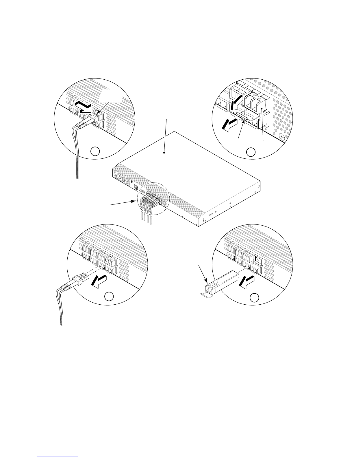
Figure 28 shows the SFP installation and removal steps for a SAN Switch 2/16V.
Cable
Release
SAN Switch
1
FC Ports
Bale
SFP
3
1
0
0-
2
4
0
V
A
C
1
.0
A
4
7
6
3
H
z
I
O
!
I
O
I
2
scale: 1/8" = 1"
SFP
4
Figure 28 Installing or removing an SFP
Installing field-replaceable units90
4.004
Page 91

A Regulatory compliance notices
This appendix covers the following topics:
• FCC EMC statement (USA), page 91
• EMC statement (Canada), page 92
• EMC statement (European Union), page 92
• European union notice, page 92
• Germany noise declaration, page 92
• VCCI EMC statement (Japan), page 93
• Japanese power cord statement, page 93
• RRL EMC statement (Korea), page 94
• Laser safety, page 95
• Battery replacement notice, page 96
FCC EMC statement (USA)
This equipment has been tested and found to comply with the limits for a Class A digital
device, pursuant to Part 15 of the FCC Rules. These limits are designed to provide reasonable
protection against harmful interference when the equipment is operated in a commercial
environment. This equipment generates, uses and can radiate radio frequency energy and, if
not installed and used in accordance with the instruction manual, may cause harmful
interference to radio communications. Operation of this equipment in a residential area is
likely to cause harmful interference, in which case the user will be required to correct the
interference at personal expense. The end user of this product should be aware that any
changes or modifications made to this equipment without the approval of Hewlett-Packard
could result in the product not meeting the Class A limits, in which case the FCC could void the
user's authority to operate the equipment.
The Regulatory Series Number for the SAN Switch 2/8V, SAN Switch 2/16V and SAN Switch
2/16N is HSTNM-N001.
The Regulatory Series Number for the SAN Switch 4/32 is HSTNM-N003.
91SAN Switch 2/8V, 2/16V, 2/16N and 4/32 installation guide
Page 92

EMC statement (Canada)
This Class A digital apparatus meets all requirements of the Canadian Interference-Causing
Equipment Regulations.
Cet appareil numérique de la Classe A respecte toutes les exigences du Règlement sur le
matériel brouilleur du Canada.
EMC statement (European Union)
This is a Class A product. In a domestic environment this product may cause radio interference,
in which case the user may be required to take adequate measures.
European union notice
Products bearing the CE marking comply with the EMC Directive (89/336/EEC) and the Low
Voltage Directive (73/23/EEC) issued by the Commission of the European Community and if
this product has telecommunication functionality, the R&TTE Directive (1999/5/EC).
Compliance with these directives implies conformity to the following European Norms (in
parentheses are the equivalent international standards and regulations):
• EN 55022 (CISPR 22)—Electromagnetic Interference
• EN55024 (IEC61000-4-2, 3, 4, 5, 6, 8, 11)—Electromagnetic Immunity
• EN61000-3-2 (IEC61000-3-2)—Power Line Harmonics
• EN61000-3-3 (IEC61000-3-3)—Power Line Flicker
• EN 60950 (IEC 60950)—Product Safety
Germany noise declaration
Schalldruckpegel Lp = 46.1 dB(A)Am Arbeitsplatz (operator position) Normaler Betrieb
(normal operation) Nach ISO 7779:1999 (Typprüfung)
Regulatory compliance notices92
Page 93
VCCI EMC statement (Japan)
Japanese power cord statement
93SAN Switch 2/8V, 2/16V, 2/16N and 4/32 installation guide
Page 94
RRL EMC statement (Korea)
Regulatory compliance notices94
Page 95

Laser safety
A. Certification and Classification Information
When equipped with native Fibre Channel adapters, this product contains a laser internal to
the small form factor pluggable (SFP) transceiver modules.
In the USA, the SFP module is certified as a Class 1 Laser product, conforming to the
requirements contained in Department Of Health and Human Services (DHHS) regulation 21
CFR, Subchapter J. The certification is indicated by a label on the metal SFP housing.
Outside the USA, the SFP is certified as a Class 1 Laser product conforming to requirements
contained in IEC 825-1:1993 and EN60825-1:1994, including Amendment 11:1996.
The SFP includes the following certifications:
• UL Recognized Component (USA)
• CSA Certified Component (Canada)
• TUV Certified Component (European Union)
• CB Certificate (Worldwide)
The following figure shows the Class 1 information label that appears on the metal housing of
the SFP.
CLASS 1 LASER PRODUCT 21 CFR(J)
B. Product Information
Each communications port consists of a transmitter and receiver optical subassembly. The
transmitter subassembly contains internally a semiconductor laser diode in the wavelength of
either 850 nanometers (shortwave laser) or 1310 nanometers (longwave laser).
Class 1 Laser products are not considered hazardous.
C. Usage Restrictions
Failure to comply with these usage restrictions may result in incorrect operation of the system
and points of access may emit laser radiation above the Class 1 limits established by the IEC
and U.S. DHHS.
95SAN Switch 2/8V, 2/16V, 2/16N and 4/32 installation guide
Page 96

WARNING! Use of controls or adjustments or performance of procedures other than those
specified herein or in the laser product’s installation guide may result in hazardous radiation
exposure. To reduce the risk of exposure to hazardous radiation: Do not try to open the module
enclosure. There are no user-serviceable components inside. Do not operate controls, make
adjustments, or perform procedures to the laser device other than those specified herein. Allow
only HP Authorized Service technicians to repair the unit.
Battery replacement notice
Your switch is equipped with a lithium manganese dioxide, a vanadium pentoxide, or an
alkaline internal battery or battery pack. There is a danger of explosion and risk of personal
injury if the battery is incorrectly replaced or mistreated. Replacement is to be done by an HP
authorized service provider using the HP spare designated for this product. For more
information about battery replacement or proper disposal, contact your HP authorized reseller
or your authorized service provider.
WARNING! Your switch contains an internal lithium manganese dioxide, a vanadium
pentoxide, or an alkaline battery. There is risk of fire and burns if the battery is not handled
properly. To reduce the risk of personal injury:
— Do not attempt to recharge the battery.
— Do not expose to temperatures higher than 140°F (60°C).
— Do not disassemble, crush, puncture, short external contacts, or dispose of in fire or
water.
Batteries, battery packs, and accumulators should not be disposed of with the general
household waste. Please use the public collection system for recycling or proper disposal or
return them to HP, your authorized HP partners, or their agents.
Regulatory compliance notices96
Page 97

B Electrostatic discharge
To prevent damaging the system, be aware of the precautions you need to follow when setting
up the system or handling parts. A discharge of static electricity from a finger or other
conductor may damage system boards or other static-sensitive devices. This type of damage
may reduce the life expectancy of the device
To prevent electrostatic damage, observe the following precautions:
• Avoid hand contact by transporting and storing products in static-safe containers.
• Keep electrostatic-sensitive parts in their containers until they arrive at static-free
workstations.
• Place parts on a grounded surface before removing them from their containers.
• Avoid touching pins, leads, or circuitry.
• Always make sure you are properly grounded when touching a static-sensitive component
or assembly.
Grounding methods
There are several methods for grounding. Use one or more of the following methods when
handling or installing electrostatic-sensitive parts:
• Use a wrist strap connected by a ground cord to a grounded workstation or chassis. Wrist
straps are flexible straps with a minimum of 1 megohm ± 10 percent resistance in the
ground cords. To provide proper ground, wear the strap snug against the skin.
• Use heel straps, toe straps, or boot straps at standing workstations. Wear the straps on both
feet when standing on conductive floors or dissipating floor mats.
• Use conductive field service tools.
• Use a portable field service kit with a folding static-dissipating work mat.
If you do not have any of the suggested equipment for proper grounding, have an HP
authorized reseller install the part.
97SAN Switch 2/8V, 2/16V, 2/16N and 4/32 installation guide
Page 98

NOTE: For more information on static electricity, or for assistance with product installation,
contact your HP authorized reseller.
Electrostatic discharge98
Page 99

C SAN Switch technical specifications
This appendix provides the following information:
• General specifications, page 100
• Weight and physical dimensions, page 102
• Facility requirements, page 103
• Environmental requirements, page 104
• Data transmission ranges, page 105
• Fibre Channel port specifications, page 107
• Serial port specifications, page 107
• Power supply specifications, page 109
• Memory, page 110
• Supported SFPs, page 111
• Supported HBAs, page 111
99SAN Switch 2/8V, 2/16V, 2/16N and 4/32 installation guide
Page 100

General specifications
Table 26 lists general specifications.
Table 26 General specifications
Specification Description
Configurable port types F_Port, FL_Port, and E_Port
EMC emissions An operating SAN Switch conforms to the emissions requirements
specified by the following regulations:
• FCC Rules & Regulations, Part 15 subpart B, Class A
• CSA C108.8 Class A
• VCCI Class A ITE
• CISPR 22 Class A
• EN55022 Class A
• AS/NZF 3548: 1995 Class A
• Korean EMC Requirements
• BSMI Standard CNS 13438
• EMC Directive 89/336/EEC
• EN5022 Level A
• EN50082–2/EN55024: 1998
SAN Switch technical specifications100
 Loading...