

HP StorageWorks 2/32, StorageWorks SAN Switch 2/32 Installation Manual

Installation
Guide
hp StorageWorks
SAN Switch 2/32
Version 4.2.x
Fourth Edition (May 2004)
Part Number: AA-RTQVD-TE
This installation guide provides basic procedures for setting up, configuring, and managing the
SAN Switch 2/32 and SAN Switch 2/32 power pack models.

© Copyright 1999-2004 Hewlett-Packard Development Company, L.P.
Hewlett-Packard Company makes no warranty of any kind with regard to this material, including, but not limited to,
the implied warranties of merchantability and fitness for a particular purpose. Hewlett-Packard shall not be liable for
errors contained herein or for incidental or consequential damages in connection with the furnishing, performance,
or use of this material.
This document contains proprietary information, which is protected by copyright. No part of this document may be
photocopied, reproduced, or translated into another language without the prior written consent of Hewlett-Packard.
The information contained in this document is subject to change without notice.
Compaq Computer Corporation is a wholly-owned subsidiary of Hewlett-Packard Company.
Microsoft®, MS Windows®, Windows®, and Windows NT® are U.S. registered trademarks of Microsoft
Corporation.
UNIX® is a registered trademark of The Open Group.
Hewlett-Packard Company shall not be liable for technical or editorial errors or omissions contained herein. The
information is provided “as is” without warranty of any kind and is subject to change without notice. The warranties
for Hewlett-Packard Company products are set forth in the express limited warranty statements for such products.
Nothing herein should be construed as constituting an additional warranty.
Printed in the U.S.A.
SAN Switch 2/32 Version 4.2.x Installation Guide
Fourth Edition (May 2004)
Part Number: AA-RTQVD-TE

contents
About this Guide. . . . . . . . . . . . . . . . . . . . . . . . . . . . . . . . . . . . . . . . . . . . . . . . . . . .7
Audience. . . . . . . . . . . . . . . . . . . . . . . . . . . . . . . . . . . . . . . . . . . . . . . . . . . . . . . . . . . . . . . . . . 8
Related Documentation . . . . . . . . . . . . . . . . . . . . . . . . . . . . . . . . . . . . . . . . . . . . . . . . . . . . . . 8
Conventions . . . . . . . . . . . . . . . . . . . . . . . . . . . . . . . . . . . . . . . . . . . . . . . . . . . . . . . . . . . . . . . 8
Document Conventions . . . . . . . . . . . . . . . . . . . . . . . . . . . . . . . . . . . . . . . . . . . . . . . . . . . 9
Text Symbols . . . . . . . . . . . . . . . . . . . . . . . . . . . . . . . . . . . . . . . . . . . . . . . . . . . . . . . . . . . 9
Equipment Symbols . . . . . . . . . . . . . . . . . . . . . . . . . . . . . . . . . . . . . . . . . . . . . . . . . . . . . 10
Rack Stability . . . . . . . . . . . . . . . . . . . . . . . . . . . . . . . . . . . . . . . . . . . . . . . . . . . . . . . . . . . . . 11
Getting Help . . . . . . . . . . . . . . . . . . . . . . . . . . . . . . . . . . . . . . . . . . . . . . . . . . . . . . . . . . . . . . 11
HP Technical Support . . . . . . . . . . . . . . . . . . . . . . . . . . . . . . . . . . . . . . . . . . . . . . . . . . . 11
HP Storage Website . . . . . . . . . . . . . . . . . . . . . . . . . . . . . . . . . . . . . . . . . . . . . . . . . . . . . 12
HP Authorized Reseller . . . . . . . . . . . . . . . . . . . . . . . . . . . . . . . . . . . . . . . . . . . . . . . . . . 12
1 Overview . . . . . . . . . . . . . . . . . . . . . . . . . . . . . . . . . . . . . . . . . . . . . . . . . . . . . . . .13
SAN Switch 2/32 Features . . . . . . . . . . . . . . . . . . . . . . . . . . . . . . . . . . . . . . . . . . . . . . . . . . . 14
Firmware . . . . . . . . . . . . . . . . . . . . . . . . . . . . . . . . . . . . . . . . . . . . . . . . . . . . . . . . . . . . . 14
Hardware . . . . . . . . . . . . . . . . . . . . . . . . . . . . . . . . . . . . . . . . . . . . . . . . . . . . . . . . . . . . . 14
Port Side of the SAN Switch 2/32. . . . . . . . . . . . . . . . . . . . . . . . . . . . . . . . . . . . . . . 15
Optical Ports . . . . . . . . . . . . . . . . . . . . . . . . . . . . . . . . . . . . . . . . . . . . . . . . . . . . . . . 15
Fan Assembly Side of the SAN Switch 2/32. . . . . . . . . . . . . . . . . . . . . . . . . . . . . . . 16
Optional Hardware Kits . . . . . . . . . . . . . . . . . . . . . . . . . . . . . . . . . . . . . . . . . . . . . . . . . . . . . 17
Contents
2 Installing the SAN Switch 2/32 . . . . . . . . . . . . . . . . . . . . . . . . . . . . . . . . . . . . . . . .19
Unpack and Verify Carton Contents. . . . . . . . . . . . . . . . . . . . . . . . . . . . . . . . . . . . . . . . . . . . 20
Locating SAN Switch 2/32 Serial Numbers. . . . . . . . . . . . . . . . . . . . . . . . . . . . . . . . . . . . . . 23
Installation Guidelines . . . . . . . . . . . . . . . . . . . . . . . . . . . . . . . . . . . . . . . . . . . . . . . . . . . . . . 23
Selecting an Operating Location . . . . . . . . . . . . . . . . . . . . . . . . . . . . . . . . . . . . . . . . . . . 23
Cooling Requirements . . . . . . . . . . . . . . . . . . . . . . . . . . . . . . . . . . . . . . . . . . . . . . . . . . . 24
Power Requirements . . . . . . . . . . . . . . . . . . . . . . . . . . . . . . . . . . . . . . . . . . . . . . . . . . . . 25
Setting Up the Switch as a Stand-alone Unit . . . . . . . . . . . . . . . . . . . . . . . . . . . . . . . . . . . . . 25
3SAN Switch 2/32 Version 4.2.x Installation Guide

Contents
Installing the Switch in a Rack Using the SAN Switch Rack Mount Kit. . . . . . . . . . . . . . . . 26
Connecting AC Power . . . . . . . . . . . . . . . . . . . . . . . . . . . . . . . . . . . . . . . . . . . . . . . . . . . . . . 38
Power On Self-Test. . . . . . . . . . . . . . . . . . . . . . . . . . . . . . . . . . . . . . . . . . . . . . . . . . . . . . . . . 39
Checking POST Results. . . . . . . . . . . . . . . . . . . . . . . . . . . . . . . . . . . . . . . . . . . . . . . . . . 39
Configuring SAN Switch 2/32 Network Addressing . . . . . . . . . . . . . . . . . . . . . . . . . . . . . . . 39
Requirements . . . . . . . . . . . . . . . . . . . . . . . . . . . . . . . . . . . . . . . . . . . . . . . . . . . . . . . . . . 40
Setting Network Addresses via a Serial Connection . . . . . . . . . . . . . . . . . . . . . . . . . . . . 40
Connecting the SAN Switch 2/32 to the LAN . . . . . . . . . . . . . . . . . . . . . . . . . . . . . . . . . . . . 43
Core Switch PID Format Summary . . . . . . . . . . . . . . . . . . . . . . . . . . . . . . . . . . . . . . . . . . . . 44
Mixed Fabric Environment with Different Switch Platforms . . . . . . . . . . . . . . . . . . . . . 44
Optional Configuration Settings. . . . . . . . . . . . . . . . . . . . . . . . . . . . . . . . . . . . . . . . . . . . . . . 45
Modifying Domain IDs . . . . . . . . . . . . . . . . . . . . . . . . . . . . . . . . . . . . . . . . . . . . . . . . . . 45
Specifying Custom Status Policies. . . . . . . . . . . . . . . . . . . . . . . . . . . . . . . . . . . . . . . . . . 45
Connecting the SAN Switch 2/32 to the Fabric . . . . . . . . . . . . . . . . . . . . . . . . . . . . . . . . . . . 46
Verifying Operation . . . . . . . . . . . . . . . . . . . . . . . . . . . . . . . . . . . . . . . . . . . . . . . . . . . . . 47
Installing Multiple Switches into an Existing SAN . . . . . . . . . . . . . . . . . . . . . . . . . . . . . . . . 48
Recommendations for Cable Management. . . . . . . . . . . . . . . . . . . . . . . . . . . . . . . . . . . . . . . 49
3 Managing the SAN Switch 2/32 . . . . . . . . . . . . . . . . . . . . . . . . . . . . . . . . . . . . . . .51
Interpreting LED Activity. . . . . . . . . . . . . . . . . . . . . . . . . . . . . . . . . . . . . . . . . . . . . . . . . . . . 52
LEDs on the Port Side of the Switch . . . . . . . . . . . . . . . . . . . . . . . . . . . . . . . . . . . . . . . . 52
LEDs on the Non-Port Side of the SAN Switch 2/32 . . . . . . . . . . . . . . . . . . . . . . . . . . . 55
Management Overview. . . . . . . . . . . . . . . . . . . . . . . . . . . . . . . . . . . . . . . . . . . . . . . . . . . . . . 58
Optional Management Feature – Fabric Manager . . . . . . . . . . . . . . . . . . . . . . . . . . . . . . 59
Displaying the Optional Feature Licenses. . . . . . . . . . . . . . . . . . . . . . . . . . . . . . . . . 59
Running Basic Switch Operations Using Telnet . . . . . . . . . . . . . . . . . . . . . . . . . . . . . . . . . . 60
Logging into the SAN Switch 2/32 . . . . . . . . . . . . . . . . . . . . . . . . . . . . . . . . . . . . . . . . . 60
Changing the Admin Password and User ID . . . . . . . . . . . . . . . . . . . . . . . . . . . . . . . . . . 60
Configuring the IP and Fibre Channel Address. . . . . . . . . . . . . . . . . . . . . . . . . . . . . . . . 61
Displaying Devices within the Fabric . . . . . . . . . . . . . . . . . . . . . . . . . . . . . . . . . . . . . . . 62
Checking the Firmware Version . . . . . . . . . . . . . . . . . . . . . . . . . . . . . . . . . . . . . . . . . . . 62
Setting the Switch Date and Time . . . . . . . . . . . . . . . . . . . . . . . . . . . . . . . . . . . . . . . . . . 62
Displaying Switch Configuration Settings. . . . . . . . . . . . . . . . . . . . . . . . . . . . . . . . . . . . 63
SAN Switch 2/32 Diagnostics . . . . . . . . . . . . . . . . . . . . . . . . . . . . . . . . . . . . . . . . . . . . . . . . 63
Interpreting POST Results . . . . . . . . . . . . . . . . . . . . . . . . . . . . . . . . . . . . . . . . . . . . . . . . 63
Additional Diagnostic Tests. . . . . . . . . . . . . . . . . . . . . . . . . . . . . . . . . . . . . . . . . . . . . . . 64
Field Replaceable Units . . . . . . . . . . . . . . . . . . . . . . . . . . . . . . . . . . . . . . . . . . . . . . . . . . . . . 64
Power Supplies. . . . . . . . . . . . . . . . . . . . . . . . . . . . . . . . . . . . . . . . . . . . . . . . . . . . . . . . . 64
Fan Assemblies . . . . . . . . . . . . . . . . . . . . . . . . . . . . . . . . . . . . . . . . . . . . . . . . . . . . . . . . 65
4 SAN Switch 2/32 Version 4.2.x Installation Guide

Contents
Motherboard Assembly . . . . . . . . . . . . . . . . . . . . . . . . . . . . . . . . . . . . . . . . . . . . . . . . . . 66
4 Backing Up the Configuration and Upgrading Firmware. . . . . . . . . . . . . . . . . . . . . .67
Backing Up System Configuration Settings. . . . . . . . . . . . . . . . . . . . . . . . . . . . . . . . . . . . . . 68
Restoring the System Configuration Settings. . . . . . . . . . . . . . . . . . . . . . . . . . . . . . . . . . . . . 69
Upgrading or Restoring Switch Firmware . . . . . . . . . . . . . . . . . . . . . . . . . . . . . . . . . . . . . . . 69
Downloading Firmware from the HP Website. . . . . . . . . . . . . . . . . . . . . . . . . . . . . . . . . . . . 70
A Technical Specifications . . . . . . . . . . . . . . . . . . . . . . . . . . . . . . . . . . . . . . . . . . . . . .71
Dimensions . . . . . . . . . . . . . . . . . . . . . . . . . . . . . . . . . . . . . . . . . . . . . . . . . . . . . . . . . . . . . . . 72
Power Supply Specifications . . . . . . . . . . . . . . . . . . . . . . . . . . . . . . . . . . . . . . . . . . . . . . . . . 72
Environmental Requirements . . . . . . . . . . . . . . . . . . . . . . . . . . . . . . . . . . . . . . . . . . . . . . . . . 73
Memory Specifications. . . . . . . . . . . . . . . . . . . . . . . . . . . . . . . . . . . . . . . . . . . . . . . . . . . . . . 73
Serial Port Specifications . . . . . . . . . . . . . . . . . . . . . . . . . . . . . . . . . . . . . . . . . . . . . . . . . . . . 74
B Regulatory Compliance Notices . . . . . . . . . . . . . . . . . . . . . . . . . . . . . . . . . . . . . . . .75
FCC EMC Statement (USA) . . . . . . . . . . . . . . . . . . . . . . . . . . . . . . . . . . . . . . . . . . . . . . . . . 76
EMC Statement (Canada). . . . . . . . . . . . . . . . . . . . . . . . . . . . . . . . . . . . . . . . . . . . . . . . . . . . 76
EMC Statement (European Union). . . . . . . . . . . . . . . . . . . . . . . . . . . . . . . . . . . . . . . . . . . . . 76
Germany Noise Declaration . . . . . . . . . . . . . . . . . . . . . . . . . . . . . . . . . . . . . . . . . . . . . . . . . . 76
VCCI EMC Statement (Japan) . . . . . . . . . . . . . . . . . . . . . . . . . . . . . . . . . . . . . . . . . . . . . . . . 77
BSMI EMC Statement (Taiwan) . . . . . . . . . . . . . . . . . . . . . . . . . . . . . . . . . . . . . . . . . . . . . . 77
RRL EMC Statement (Korea) . . . . . . . . . . . . . . . . . . . . . . . . . . . . . . . . . . . . . . . . . . . . . . . . 77
Laser Safety . . . . . . . . . . . . . . . . . . . . . . . . . . . . . . . . . . . . . . . . . . . . . . . . . . . . . . . . . . . . . . 78
A. Certification and Classification Information . . . . . . . . . . . . . . . . . . . . . . . . . . . . 78
B. Product Information . . . . . . . . . . . . . . . . . . . . . . . . . . . . . . . . . . . . . . . . . . . . . . . 78
C. Usage Restrictions . . . . . . . . . . . . . . . . . . . . . . . . . . . . . . . . . . . . . . . . . . . . . . . . 78
Battery Replacement Notice. . . . . . . . . . . . . . . . . . . . . . . . . . . . . . . . . . . . . . . . . . . . . . . . . . 79
C Electrostatic Discharge. . . . . . . . . . . . . . . . . . . . . . . . . . . . . . . . . . . . . . . . . . . . . . .81
Grounding Methods . . . . . . . . . . . . . . . . . . . . . . . . . . . . . . . . . . . . . . . . . . . . . . . . . . . . . . . . 82
Glossary. . . . . . . . . . . . . . . . . . . . . . . . . . . . . . . . . . . . . . . . . . . . . . . . . . . . . . . . .83
Index . . . . . . . . . . . . . . . . . . . . . . . . . . . . . . . . . . . . . . . . . . . . . . . . . . . . . . . . . . .95
Figures
1 Port side of the SAN Switch 2/32 . . . . . . . . . . . . . . . . . . . . . . . . . . . . . . . . . . . . . . . . . . 19
2 Fan assembly side of the SAN Switch 2/32. . . . . . . . . . . . . . . . . . . . . . . . . . . . . . . . . . . 20
5SAN Switch 2/32 Version 4.2.x Installation Guide

Contents
3 Shipping carton contents . . . . . . . . . . . . . . . . . . . . . . . . . . . . . . . . . . . . . . . . . . . . . . . . . 25
4 Securing the inner slide rails to the switch. . . . . . . . . . . . . . . . . . . . . . . . . . . . . . . . . . . . 33
5 Attaching the rear rack mount brackets . . . . . . . . . . . . . . . . . . . . . . . . . . . . . . . . . . . . . . 34
6 Attaching the outer slide rails to the HP 9000 Series rack. . . . . . . . . . . . . . . . . . . . . . . . 37
7 Sliding the SAN Switch 2/32 into an HP 9000 Series rack . . . . . . . . . . . . . . . . . . . . . . . 39
8 Installing the mounting brackets . . . . . . . . . . . . . . . . . . . . . . . . . . . . . . . . . . . . . . . . . . . 41
9 Installing the Tinnerman clips . . . . . . . . . . . . . . . . . . . . . . . . . . . . . . . . . . . . . . . . . . . . . 42
10 Installing the rubber washers . . . . . . . . . . . . . . . . . . . . . . . . . . . . . . . . . . . . . . . . . . . . . . 43
11 Assembling the inner rails . . . . . . . . . . . . . . . . . . . . . . . . . . . . . . . . . . . . . . . . . . . . . . . . 44
12 Connecting the power cords. . . . . . . . . . . . . . . . . . . . . . . . . . . . . . . . . . . . . . . . . . . . . . . 45
13 Connecting the Serial cable . . . . . . . . . . . . . . . . . . . . . . . . . . . . . . . . . . . . . . . . . . . . . . . 48
14 Connecting the Ethernet cable . . . . . . . . . . . . . . . . . . . . . . . . . . . . . . . . . . . . . . . . . . . . . 51
15 Inserting a cable into an SFP . . . . . . . . . . . . . . . . . . . . . . . . . . . . . . . . . . . . . . . . . . . . . . 57
16 LEDs on port side of SAN Switch 2/32. . . . . . . . . . . . . . . . . . . . . . . . . . . . . . . . . . . . . . 62
17 LEDs on non-port side of SAN Switch 2/32 . . . . . . . . . . . . . . . . . . . . . . . . . . . . . . . . . . 65
18 Power supplies and fan assemblies locations. . . . . . . . . . . . . . . . . . . . . . . . . . . . . . . . . . 75
19 Power supplies and fan assemblies locations. . . . . . . . . . . . . . . . . . . . . . . . . . . . . . . . . . 76
20 ioscan output . . . . . . . . . . . . . . . . . . . . . . . . . . . . . . . . . . . . . . . . . . . . . . . . . . . . . . . . . . 98
21 ioscan -funC disk command output . . . . . . . . . . . . . . . . . . . . . . . . . . . . . . . . . . . . . . . . . 99
Tables
1 Document Conventions . . . . . . . . . . . . . . . . . . . . . . . . . . . . . . . . . . . . . . . . . . . . . . . . . . 11
2 SAN Switch 2/32 Orderable Hardware . . . . . . . . . . . . . . . . . . . . . . . . . . . . . . . . . . . . . . 21
3 Shipping Carton Contents . . . . . . . . . . . . . . . . . . . . . . . . . . . . . . . . . . . . . . . . . . . . . . . . 26
4 Front Panel LED Patterns During Normal Operation . . . . . . . . . . . . . . . . . . . . . . . . . . . 63
5 Non-Port Side LED Patterns During Normal Operation . . . . . . . . . . . . . . . . . . . . . . . . . 66
6 Management Options for the SAN Switch 2/32 . . . . . . . . . . . . . . . . . . . . . . . . . . . . . . . 68
7 Physical Specifications. . . . . . . . . . . . . . . . . . . . . . . . . . . . . . . . . . . . . . . . . . . . . . . . . . . 86
8 Power Supply Specifications . . . . . . . . . . . . . . . . . . . . . . . . . . . . . . . . . . . . . . . . . . . . . . 87
9 Environmental Requirements. . . . . . . . . . . . . . . . . . . . . . . . . . . . . . . . . . . . . . . . . . . . . . 88
10 Cabling Pinouts if Pin 7 is Used . . . . . . . . . . . . . . . . . . . . . . . . . . . . . . . . . . . . . . . . . . . 90
6 SAN Switch 2/32 Version 4.2.x Installation Guide

about this
guide
This installation guide provides information to help you:
■ Set up and configure the HP StorageWorks SAN Switch 2/32.
■ Maintain and operate the switch.
About this Guide
About this Guide
This preface discusses the following topics:
■ Audience, page 8
■ Related Documentation, page 8
■ Conventions, page 8
■ Rack Stability, page 11
■ Getting Help, page 11
7SAN Switch 2/32 Version 4.2.x Installation Guide

About this Guide
Audience
This book is intended for use by customers who purchased the SAN Switch 2/32,
and for authorized service providers who are experienced with the following:
■ Configuration aspects of customer Storage Area Network (SAN) fabrics
■ Customer host environments, such as Windows
IBM AIX
■ Web Tools Graphical User Interface (GUI), for configuring the switch via a
supported Web browser
Related Documentation
For a list of related documents included with this product, see the Related
Documents section of the HP StorageWorks Fabric OS 4.2.x Release Notes.
For the latest information, documentation and firmware releases, please visit the
following HP StorageWorks website:
®
2000, Windows NT®, and
http://www.hp.com/country/us/eng/prodserv/storage.html
For information about Fibre Channel standards, visit the Fibre Channel
Association web site, located at:
http://www.fibrechannel.org
Conventions
Conventions consist of the following:
■ Document Conventions
■ Text Symbols
■ Equipment Symbols
8 SAN Switch 2/32 Version 4.2.x Installation Guide
Document Conventions
The document conventions included in Table 1 apply in most cases.
Table 1: Document Conventions
Cross-reference links Blue text: Figure 1
About this Guide
Element Convention
Text Symbols
Key and field names, menu items,
buttons, and dialog box titles
File names, application names, and text
emphasis
User input, command and directory
names, and system responses (output
and messages)
Variables
Website addresses
Bold
Italics
Monospace font
COMMAND NAMES
monospace font unless they are case
sensitive
are uppercase
<monospace, italic font>
Blue, underlin
example:
ed sans serif font text, for
http://www.hp.com
The following symbols may be found in the text of this guide. They have the
following meanings.
WARNING: Text set off in this manner indicates that failure to follow
directions in the warning could result in bodily harm or death.
Caution: Text set off in this manner indicates that failure to follow directions
could result in damage to equipment or data.
Note: Text set off in this manner presents commentary, sidelights, or interesting points
of information.
SAN Switch 2/32 Version 4.2.x Installation Guide
9
About this Guide
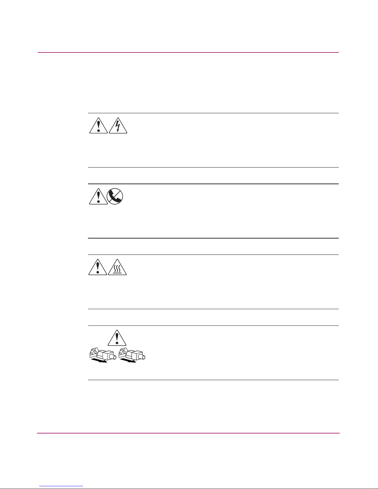
Equipment Symbols
The following equipment symbols may be found on hardware discussed in this
document:
Any enclosed surface or area of the equipment marked with these
symbols indicates the presence of electrical shock hazards. Enclosed
area contains no operator serviceable parts.
WARNING: To reduce the risk to personal injury from electrical shock
hazards, do not open this enclosure.
Any RJ-45 receptacle marked with these symbols indicates a network
interface connection.
WARNING: To reduce the risk of electrical shock, fire, or damage to the
equipment, do not plug telephone or telecommunications connectors
into this receptacle.
Any surface or area of the equipment marked with these symbols
indicates the presence of a hot surface or hot component. Contact with
this surface could result in injury.
WARNING: To reduce the risk to personal injury from a hot component,
allow the surface to cool before touching.
Power supplies or systems marked with these symbols indicate the
presence of multiple sources of power.
WARNING: To reduce the risk to personal injury from electrical
shock, remove all power cords to completely disconnect power
from the power supplies and systems.
10 SAN Switch 2/32 Version 4.2.x Installation Guide
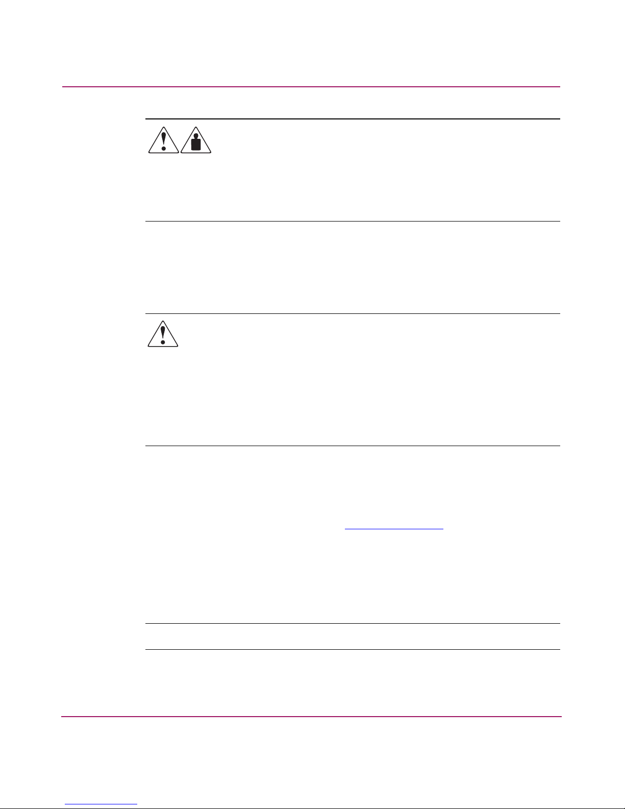
Rack Stability
Rack stability protects personnel and equipment.
About this Guide
Any product or assembly marked with these symbols indicates that the
component exceeds the recommended weight for one individual to
handle safely.
WARNING: To reduce the risk to personal injury or damage to the
equipment, observe local occupational health and safety requirements
and guidelines for manually handling material.
WARNING: To reduce the risk of personal injury or damage to the
equipment, be sure that:
■ The leveling jacks are extended to the floor.
■ The full weight of the rack rests on the leveling jacks.
■ In single rack installations, the stabilizing feet are attached to the rack.
■ In multiple rack installations, the racks are coupled.
■ Only one rack component is extended at any time. A rack may become
unstable if more than one rack component is extended for any reason.
Getting Help
If you still have a question after reading this guide, contact an HP authorized
service provider or access our website:
HP Technical Support
In North America, call technical support at 1-800-652-6672, available 24 hours a
day, 7 days a week.
Note: For continuous quality improvement, calls may be recorded or monitored.
SAN Switch 2/32 Version 4.2.x Installation Guide
http://www.hp.com
.
11

About this Guide
Outside North America, call technical support at the nearest location. Telephone
numbers for worldwide technical support are listed on the HP website under
support:
http://thenew.hp.com/country/us/eng/support.html
Be sure to have the following information available before calling:
■ Technical support registration number (if applicable)
■ Product serial numbers
■ Product model names and numbers
■ Applicable error messages
■ Operating system type and revision level
■ Detailed, specific questions
HP Storage Website
The HP website has the latest information on this product. Access storage at
http://thenew.hp.com/country/us/eng/prodserv/storage.html
select the appropriate product or solution.
.
. From this website,
HP Authorized Reseller
For the name of your nearest HP authorized reseller:
■ In the United States, call 1-800-345-1518
■ In Canada, call 1-800-263-5868
■ Elsewhere, see the HP website for locations and telephone numbers:
http://www.hp.com
.
12 SAN Switch 2/32 Version 4.2.x Installation Guide

Overview
The HP StorageWorks SAN Switch 2/32 is a high-performance, 32-port,
2 gigabit (Gb) Fibre Channel switch that interconnects storage devices, hosts, and
servers in a Storage Area Network (SAN). It integrates Fabric Operating System
(FOS) firmware version 4.2.x or later, and is compatible with the HP
StorageWorks switch product family. The SAN Switch 2/32 operates in a fabric
containing multiple switches, or as the only switch in the fabric.
This chapter provides the following information:
■ SAN Switch 2/32 Features, page 14
■ Optional Hardware Kits, page 17
The HP StorageWorks SAN Switch 2/32 is offered in two configurations; the 2/32
and 2/32 power pack. Refer to the HP StorageWorks Fabric OS 4.2.x Release
Notes for a complete list of management features enabled on your specific switch.
Note: This guide refers to both models as the SAN Switch 2/32, unless otherwise
noted.
1
13SAN Switch 2/32 Version 4.2.x Installation Guide

Overview
SAN Switch 2/32 Features
This section provides feature-specific information.
Firmware
The SAN Switch 2/32 operates using FOS firmware version 4.2.x. The firmware
supports:
■ An optional Security feature, which provides security mechanisms at all
vulnerable points in a SAN fabric, from hosts to storage at the port, switch,
and fabric levels.
■ High-speed data traffic using Interswitch Link (ISL) trunking technology
■ Automatic rerouting through the Fabric Shortest Path First (FSPF) algorithm
■ Application Programming Interface (API), which is a protocol that allows
applications to interface with switch services
■ Per port statistics, which help technicians diagnose and isolate problem ports
without disrupting switch operations
Hardware
■ Error detection and fault isolation
■ Industry standard Management Information Base (MIB) support
■ Automatic self-discovery
■ Advanced Web Tools, which is an integrated Graphical User Interface (GUI),
to manage the SAN from a browser
The SAN Switch 2/32 consists of the following components:
■ An air-cooled 1.5-Unit chassis that can be set up as a stand-alone unit or
mounted in a standard Electronic Industries Association (EIA) 19-inch rack
■ 32 Fibre Channel ports
■ One RS-232 Serial port, designed to connect to a DTE port
■ One 10/100 Mb/s Ethernet port with an RJ-45 connector
■ Two redundant power supplies, with AC switches and built-in fans
■ Three redundant fan assemblies, hot-swappable if replaced one at a time
■ A field-replaceable motherboard assembly enclosed in a grounded EMI cage
14 SAN Switch 2/32 Version 4.2.x Installation Guide
■ Slide Rack Mount Kit
■ The following LED indicators:
— Switch Power/Status LED on the port side of the switch
— Port Readiness LED on the non-port side of the switch
— Port Status LED and Port Speed LED for each port
— Power LED on each power supply
— Fan Failure LED on each fan assembly
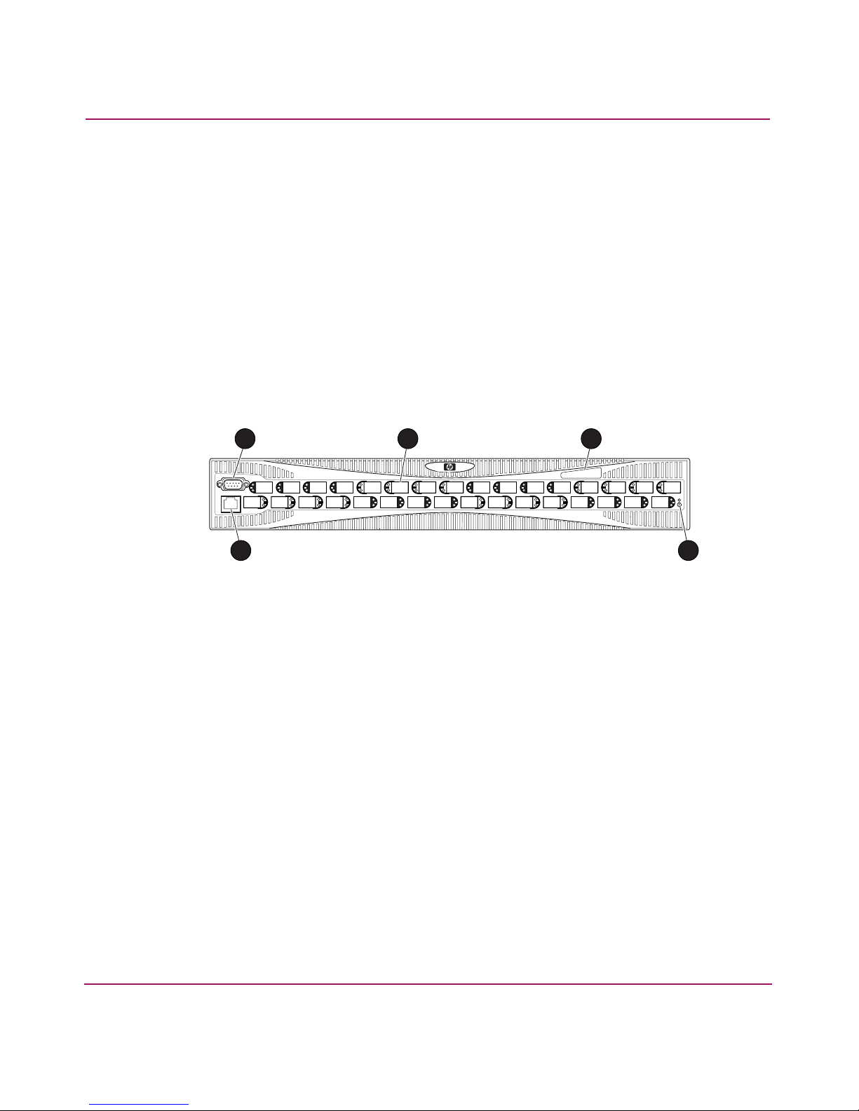
Port Side of the SAN Switch 2/32
Figure 1 shows the port side of the SAN Switch 2/32.
Overview
Optical Ports
1 3
5 4
1 Serial port
2 Fibre Channel
port
3 IP address
label
4 Power switch
5 Ethernet port
2
SHR-2568A
Figure 1: Port side of the SAN Switch 2/32
The Fibre Channel ports are numbered from left to right, with ports 0–15 in the
lower row and ports 16–31 in the upper row. The ports provide the following
functionality:
■ Automatic negotiation to highest common speed of all devices connected to
the port
■ Port interfaces compatible with Small Form Factor Pluggable (SFP)
transceivers, both short wavelength (SWL) and long wavelength (LWL)
15SAN Switch 2/32 Version 4.2.x Installation Guide

Overview
■ Universal and self-configuring: capable of becoming an F_Port (fabric
enabled), FL_Port (fabric loop enabled), or E_Port (expansion port).
The ports are color-coded into groups of four to indicate which ports can be used
in the same Interswitch Link (ISL) trunking group.
Note: ISL Trunking is an integrated software component that enables ISL trunking
groups between adjacent switches. For more information about trunking, refer to the
HP StorageWorks Fabric OS 4.2.x Features User Guide
Fan Assembly Side of the SAN Switch 2/32
Figure 2 shows the fan assembly side of the SAN Switch 2/32. This side houses
the fans with corresponding LEDs, power supplies, and the port readiness LED.
.
1 3
1 Power supply
2 Fan assembly (1 0f 3)
3 Power supply
4 Port readiness LED
2
Figure 2: Fan assembly side of the SAN Switch 2/32
4
SHR-2569A
16 SAN Switch 2/32 Version 4.2.x Installation Guide

Optional Hardware Kits
HP provides the optional hardware kits in support of the SAN Switch 2/32 shown
in Table 2.
Table 2: SAN Switch 2/32 Orderable Hardware
Accessory Part Number
Short wavelength SFP A6515A* or 300834-B21**
Long wavelength SFP, 10 km A6516A* or 300835-B21**
2m LC-to-LC Fibre Channel (fc) cable C7524A*
2m LC-to-LC multimode fc cable 221692-B21**
16m LC-to-LC fc cable C7525A*
5m LC-to-LC multimode fc cable 221692-B22**
50m LC-to-LC fc cable C7526A*
15m LC-to-LC multimode fc cable 221692-B23**
200m LC-to-LC fc cable C7527A*
Overview
30m LC-to-LC multimode fc cable 221692-B26**
50m LC-to-LC multimode fc cable 221692-B27**
2m LC-to-SC fc cable C7529A*
2m LC-to-SC multimode fc cable 221691-B21**
16m LC-to-SC fc cable C7530A*
5m LC-to-SC multimode fc cable 221691-B21**
15m LC-to-SC multimode fc cable 221691-B23**
30m LC-to-SC multimode fc cable 221691-B26**
50m LC-to-SC multimode fc cable 221691-B27**
SC female to SC female adapter C7534A*
2m LC male to SC male adapter kit C7534A*
* Premerger HP part number
** Premerger Compaq part number
17SAN Switch 2/32 Version 4.2.x Installation Guide

Overview
18 SAN Switch 2/32 Version 4.2.x Installation Guide

Installing the
SAN Switch 2/32
This chapter covers the following topics:
■ Unpack and Verify Carton Contents, page 20
■ Locating SAN Switch 2/32 Serial Numbers, page 23
■ Installation Guidelines, page 23
■ Setting Up the Switch as a Stand-alone Unit, page 25
■ Installing the Switch in a Rack Using the SAN Switch Rack Mount Kit,
page 26
■ Connecting AC Power, page 38
■ Power On Self-Test, page 39
■ Configuring SAN Switch 2/32 Network Addressing, page 39
■ Connecting the SAN Switch 2/32 to the LAN, page 43
■ Core Switch PID Format Summary, page 44
2
■ Optional Configuration Settings, page 45
■ Connecting the SAN Switch 2/32 to the Fabric, page 46
■ Installing Multiple Switches into an Existing SAN, page 48
■ Recommendations for Cable Management, page 49
19SAN Switch 2/32 Version 4.2.x Installation Guide

Installing the SAN Switch 2/32
Unpack and Verify Carton Contents
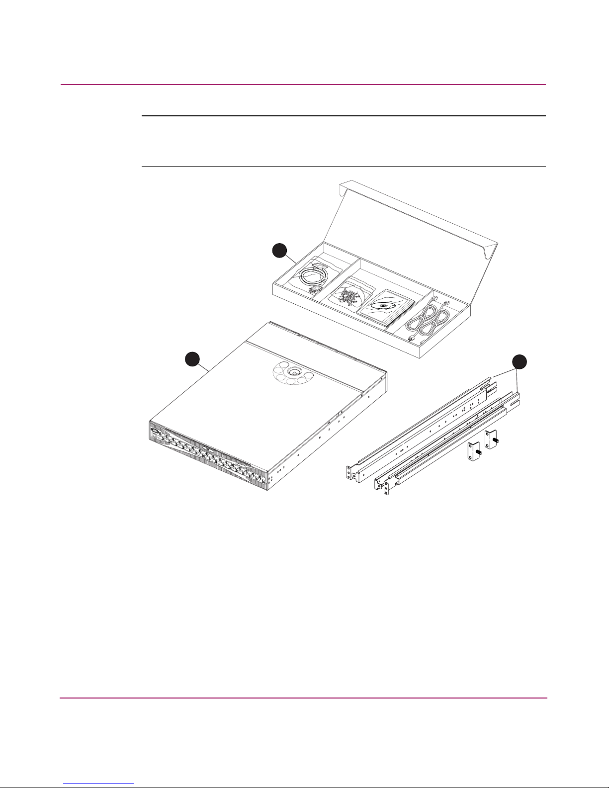
Unpack and inspect the SAN Switch 2/32 carton contents as follows:
1. Inspect the shipping container for possible damage caused during transit.
2. Unpack the shipping cartons.
3. Verify that the carton contains the items shown in Figure 3 and listed in
Table 3.
Note: If any items are damaged or missing, please contact HP or an HP authorized
reseller.
20 SAN Switch 2/32 Version 4.2.x Installation Guide
Installing the SAN Switch 2/32
Note: The Rack Mount Kit shown in Figure 3 may not represent the kit that shipped
with your switch. HP reserves the right to substitute Rack Mount Kits, providing
applicable instructions with each switch.
1
3
Figure 3: Shipping carton contents
2
SHR-2570B
21SAN Switch 2/32 Version 4.2.x Installation Guide

Installing the SAN Switch 2/32
Table 3: Shipping Carton Contents
Number Item
1
One HP StorageWorks SAN Switch 2/32 product accessories box
containing:
■ One RS-232 Serial cable (convertible to an RJ-45 connector, by
removing the adapter on the end of the cable)
■ Pouch containing rack mount hardware:
— (14) #8-32 x 3/16-inch Phillips pan-head screw with
thread lock for the SAN Switch 2/32
— (14) 8-32 x 5/16-inch Phillips pan-head SEMS screw for
use with the SAN Switch 2/8, SAN Switch 2/8V, SAN
Switch 2/16, SAN Switch 2/16V, and SAN Switch 2/16N
Note: 8-32 x 5/16-inch Phillips pan-head SEMS screw graphic is
not available for this release.
— (10) #10-32 x 1/2-inch Phillips pan-head screw with
captive star lock washer
— (8) #10 alignment washer
— (8) #10 adapter washer
— (2) 1/4-20 hex nut with captive star lock washer
— (2) 1/4-inch flat washer
■ Documentation, release notes, license, warranty, and CD
■ Two country-specific AC power cords
■ Two Power Distribution Unit (PDU) power cords (not shown in
Figure 3)
■ Four rubber mounting feet for stand-alone installations on a
table or lab bench
2
3
22 SAN Switch 2/32 Version 4.2.x Installation Guide
SAN Switch Rack Mount Kit:
■ Two rear mounting brackets
■ A right inner rail and a right outer rail
■ A left inner rail and a left outer rail
HP StorageWorks SAN Switch 2/32

Locating SAN Switch 2/32 Serial Numbers
Before contacting HP for technical support or service, obtain the three serial
numbers located on the switch. Each serial number provides specific logistical
information, identifying the device’s manufacturing location.
Installation Guidelines
Read the following sections for installation guidelines. Install the SAN Switch
2/32 in one of the following ways:
■ As a stand-alone unit on a flat surface. For instructions, see Setting Up the
Switch as a Stand-alone Unit, page 25.
■ As a fixed component using the SAN Switch rack mount kit. For instructions,
see Installing the Switch in a Rack Using the SAN Switch Rack Mount Kit,
page 26.
Selecting an Operating Location
Installing the SAN Switch 2/32
To ensure correct operation of the switch, the location where the switch is to be
used must meet the following requirements:
■ Adequate supply circuit, line fusing, and wire size, as specified by the
electrical rating on the switch nameplate.
■ An air flow of at least 300 cubic feet per minute, available in the immediate
vicinity of the switch.
■ If you are installing the switch in the HP 9000 Series or comparable EIA rack:
— All equipment installed in the rack should have a reliable branch circuit
ground connection, and should not rely on a connection to a branch
circuit, such as a power strip.
— The rack should be balanced and the installed equipment should be within
the rack’s weight limits. Make sure the rack is mechanically secured to
ensure stability in the event of an earthquake.
23SAN Switch 2/32 Version 4.2.x Installation Guide

Installing the SAN Switch 2/32
Cooling Requirements
Cooling air is drawn into the switch chassis by the fans mounted on the rear of the
chassis. The air is expelled through vents in the front (port side) of the chassis,
next to the HP logo. HP recommends installing the switch so that air intake and
exhaust for all components in the rack is flowing in the same front-to-back
direction.
Note: HP highly recommends mounting the switch in a cabinet or rack so that the fans
reside in the front of the cabinet and the ports (cables) reside in the rear of the cabinet.
Follow these guidelines to ensure proper air flow and prevent component
overheating:
■ To ensure adequate cooling, install the switch with the non-port side, which
contains the air intake vents, facing the cool-air aisle.
■ Verify that a minimum of 47 cubic feet/minute (79.8 cubic meters/hour) of air
flow is available to the air intake vents on the non-port side of the switch.
■ Verify that the ambient air temperature does not exceed 40° Celsius (104°
Fahrenheit) while the switch is operating.
Caution: Do not block air vents. The switch uses ambient air for cooling.
24 SAN Switch 2/32 Version 4.2.x Installation Guide

Power Requirements
Two AC power cords connect to the switch on either side of the rear panel. The
AC power source must meet the following requirements:
■ Primary AC Input 100–240 VAC (switch auto-senses input voltage) 47–63 Hz
■ Correctly wired primary outlet, with circuit protected by a circuit breaker and
grounded in accordance with local electrical codes
■ Adequate supply circuit, line fusing, and wire size, as specified by the
electrical rating on the switch nameplate
■ Voltage capability of 85–264 VAC
■ Input voltage frequency of 47–63 Hz
■ Power capability of 75 watts maximum
The switch has a universal power supply capable of functioning worldwide
without voltage jumpers or switches. The power supply is auto ranging in terms of
accommodating input voltages and line frequencies.
Installing the SAN Switch 2/32
Setting Up the Switch as a Stand-alone Unit
Use these procedures for setting up the switch as a stand-alone unit. The following
items are required for this setup:
■ SAN Switch 2/32
■ AC power cords and cables supplied with the switch
■ Rubber mounting feet supplied with the switch
1. Place the SAN Switch 2/32 on a flat, sturdy surface like a table or lab bench.
2. Apply the rubber feet as follows:
a. Clean the four depressions that are at each corner of the bottom of the
switch to ensure they are free of dust.
b. Place a rubber foot in each depression, with the adhesive side against the
chassis, and press into place.
Caution: HP recommends installing the rubber feet on the switch to help
prevent the switch from accidentally sliding off the table or bench.
25SAN Switch 2/32 Version 4.2.x Installation Guide

Installing the SAN Switch 2/32
3. Connect the power cables to the SAN Switch 2/32 power connectors and to a
power outlet. Ensure the power cable is routed so that it is not exposed to
stress.
4. Turn on the power to the switch (flip the AC switch to 1). The switch
automatically runs a Power On Self-Test (POST).
Caution: Do not connect the switch to the network until the IP address is
correctly set. For instructions on how to set the IP address, see “Configuring
SAN Switch 2/32 Network Addressing” on page 39.
Installing the Switch in a Rack Using the SAN Switch Rack
Mount Kit
This section provides instructions for installing the switch in an HP System/e
cabinet, or in an HP 10000 series cabinet using the HP StorageWorks SAN Switch
Rack Mount Kit supplied with your switch. The Rack Mount Kit installation
requires one technician to install a SAN Switch.
The following items are required to install the switch in a cabinet:
■ SAN Switch 2/32
■ Power cables
■ #2 Phillips screwdriver
■ 7/16-inch wrench or socket
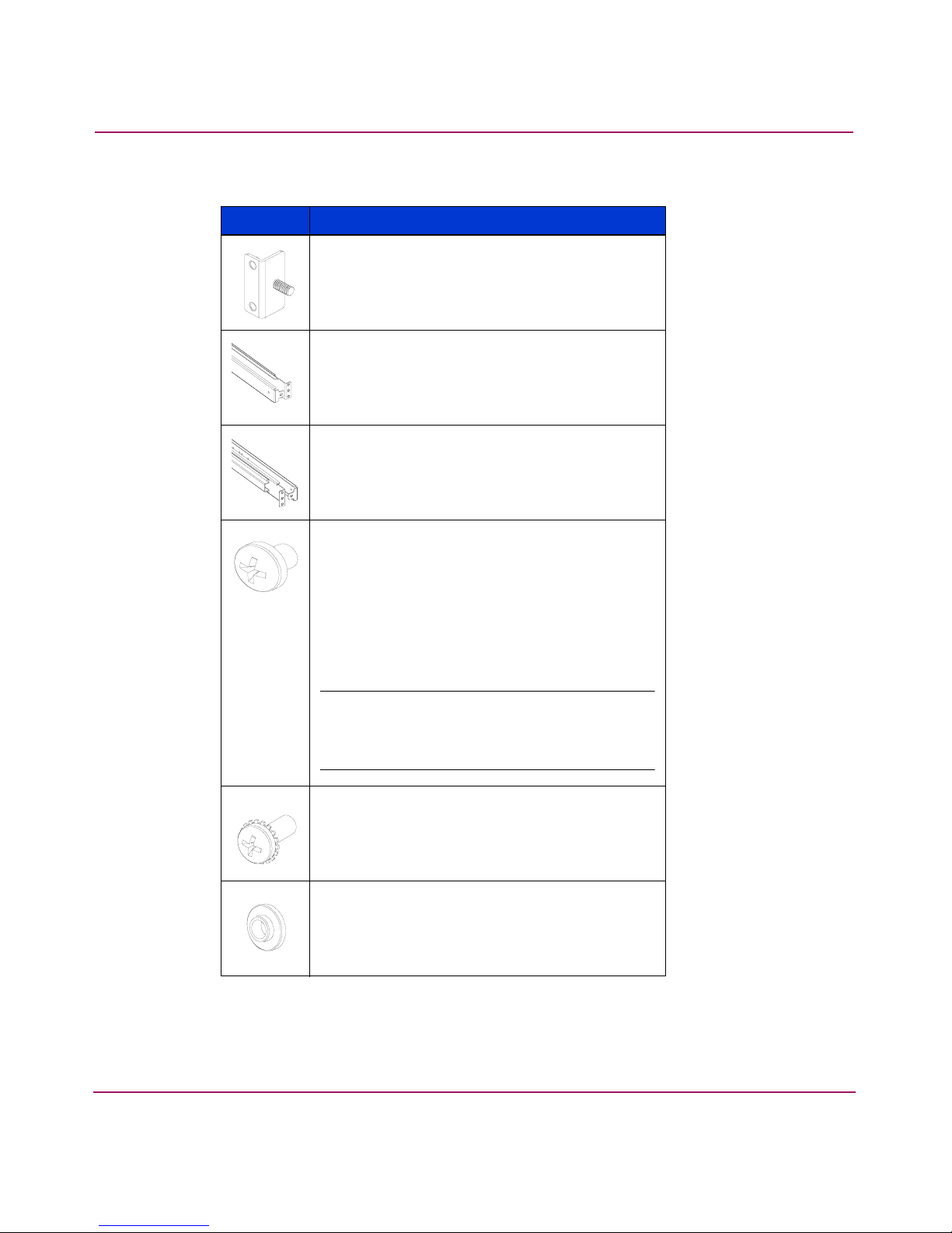
The SAN Switch Rack Mount Kit rails and rail mounting hardware listed in
Table 4.
26 SAN Switch 2/32 Version 4.2.x Installation Guide
Installing the SAN Switch 2/32
Table 4: Rack Mount Kit rails and rail mounting hardware
Item Description
(2) rear mounting brackets
A right inner rail and a right outer rail
A left inner rail and a left outer rail
(14) #8-32 x 3/16-inch Phillips pan-head
screw with thread lock for the SAN Switch
2/32 only
(14) 8-32 x 5/16-inch Phillips pan-head
SEMS screw for use with the SAN Switch
2/32.
Note: 8-32 x 5/16-inch Phillips pan-head
SEMS screw graphic is not available for this
release.
(10) #10-32 x 1/2-inch Phillips pan-head
screw with captive star lock washer
(8) #10 alignment washer
27SAN Switch 2/32 Version 4.2.x Installation Guide
Installing the SAN Switch 2/32
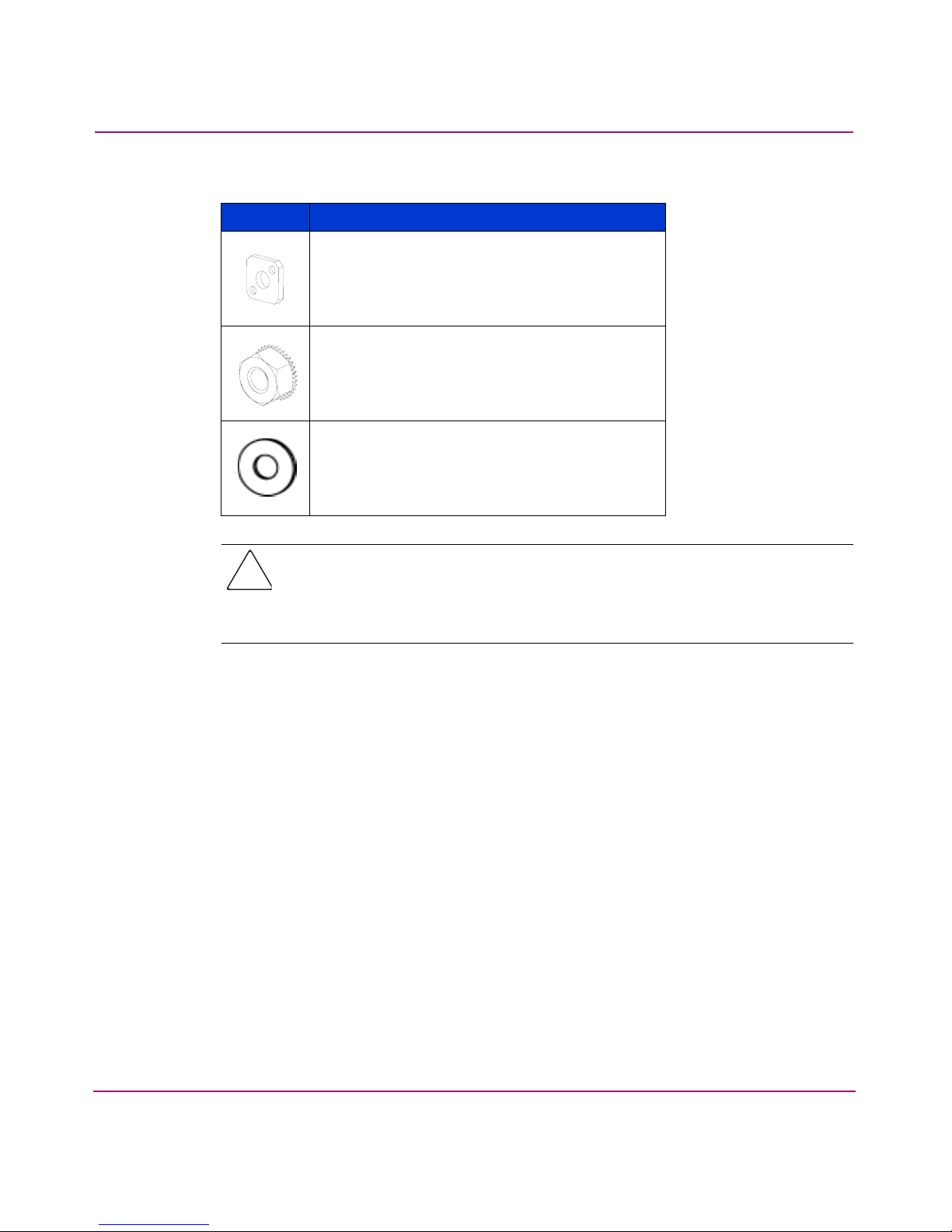
Table 4: Rack Mount Kit rails and rail mounting hardware (Continued)
Item Description
Caution: For proper air flow, the SFP media side of the SAN Switch 2/32
must face the rear of the rack. This mounting allows air to enter from the front
of the rack and to exhaust at the rear of the rack, similar to other rack-mounted
equipment. This prevents switch overheating, which may cause it to fail.
(8) #10 adapter washer
(2) 1/4-20 hex nut with captive star lock
washer
(2) 1/4-inch flat washer
To install the switch in a rack:
1. Check the contents of the shipping carton to verify that all the required parts
and hardware are available.
2. Choose a mounting location in the rack for the switch.
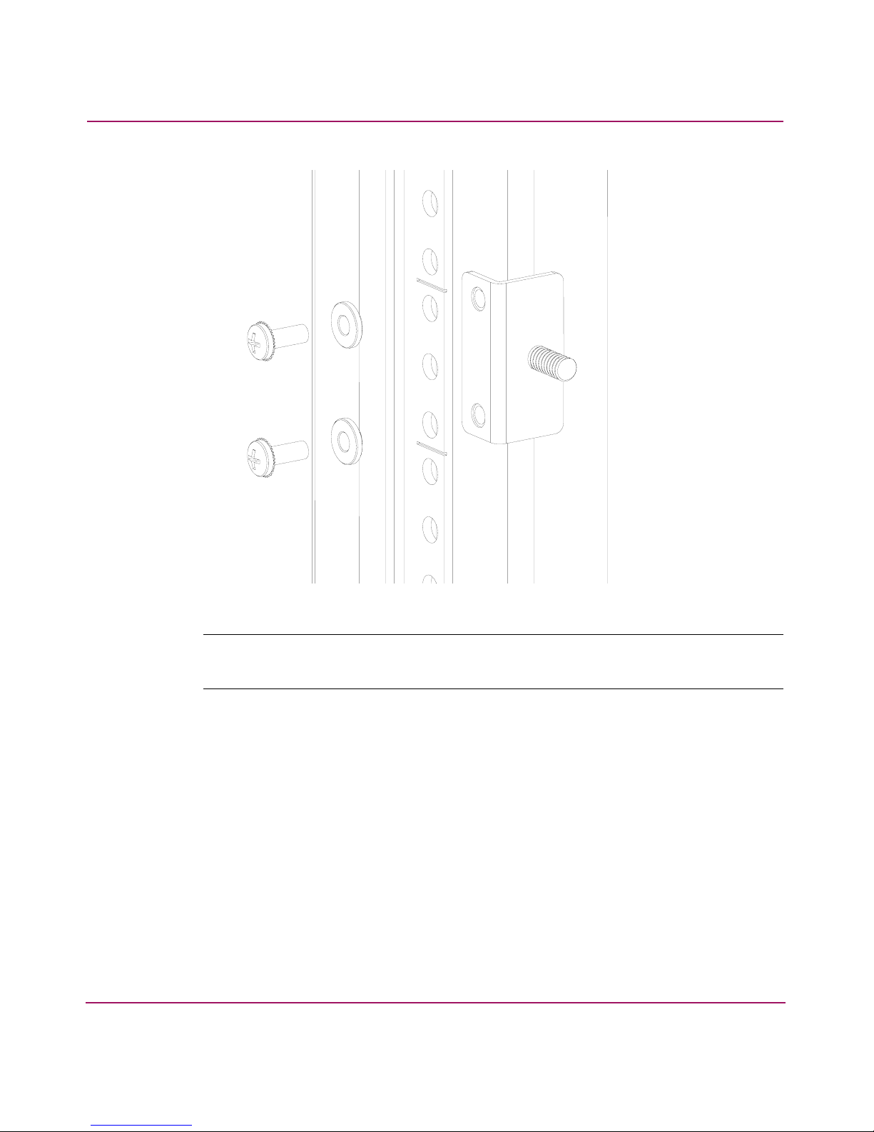
3. Attach the rear mounting brackets to the rear rack uprights by completing one
of the following steps:
— For an HP 10000 series or comparable EIA cabinet, assemble each of the
two brackets with two #10-32 x 1/2-inch Phillips pan-head screws with
captive star lock washers and two #10 adapter washers as shown in
Figure 4.
28 SAN Switch 2/32 Version 4.2.x Installation Guide

Installing the SAN Switch 2/32
Figure 4: Installing the rear mounting brackets (HP 10000 series or comparable EIA
cabinet)
— For an HP System/e rack, install each of the two rear mounting brackets
with two #10-32 x 1/2-inch Phillips pan-head screws and two #10
alignment washers as shown in Figure 5.
29SAN Switch 2/32 Version 4.2.x Installation Guide
Installing the SAN Switch 2/32
Figure 5: Installing the rear mounting brackets (HP System/e rack-left rear upright)
Note: This kit contains both left rails and right rails. The rails are marked Right and
Left.
4. Assemble the outer rails by completing the following steps:
a. Attach the left outer rail and the right outer rails to the rear mounting
brackets using two 1/4-20 hex nuts with captive star lock washers
attached loosely as shown in Figure 6. Do not tighten them; the nuts will
be tightened later in step 7 on page 37.
30 SAN Switch 2/32 Version 4.2.x Installation Guide
 Loading...