

Page 1

HP Reference Information Storage System
Administrator Guide
Version 1.6
T3559-90809
Part number: T3559-90809
econd edition: September 2007
S
Page 2

Legal and notice information
© Copyright 2004-2007 Hewlett-Packard Development Company, L.P.
Hewlett-Packard Company makes no warranty of any kind with regard to this material, including, but not limited to, the implied
warranties of merchantability and fitness for a particular purpose. H ewlett-Packard shall not be liable for errors contained herein or
for incidental or consequential damages in connection with the furnishing, performance, or use of this material.
This document contains proprietary information, which is protected by copyright. No part of this document may be photocopied,
reproduced, or translated into another language without the prior written consent of Hewlett-Packard. The information contained in
this document is subject to change without notice. The only warranties for HP products and services are set forth in the express
warranty statements accompanying such products and services. Nothing herein should be construed as constituting an additional
warranty. HP shall not be liable for technical o r editorial errors or omissions contained herein.
Microsoft® and Windows® are US registered trademarks of Microsoft Corporation. Outlook™ is a trademark of Microsoft
Corporation.
Hewlett-Packard Company shall not be liable for technical o r editorial errors or omissions contained herein. The information is
provided “as is” without warranty of any kind and is subject to change without notice. The warranties for Hewlett-Packard Company
products are set forth in the express limited warranty statements for such products. Nothing herein should be construed as
constituting an additional warranty.
Page 3

Contents
Aboutthisguide ......................... 13
Intendedaudience..................................... 13
Relateddocumentation................................... 13
Documentconventionsandsymbols ............................. 14
HPtechnicalsupport.................................... 14
Subscriptionservice .................................... 15
Otherwebsites...................................... 15
Providing feedback . . . . . . . . . . . . . . . . . . . . . . . . . . . . . . . . . . . . 15
1 RISS overview . . . . . ..................... 17
RISS........................................... 17
RIM ........................................... 17
RISSpoweron/off..................................... 18
Poweroff....................................... 18
Poweron....................................... 18
HowtorestartRISSafterapowerfailure ......................... 18
2IntroductiontoPlatformControlCenter(PCC) ............ 21
AccessingPCC ...................................... 21
Userinterfacecomponents ................................. 21
Userinterfaceorientationtips ................................ 22
Viewsforcommontasks .................................. 23
Updating views b efore printing . . . . . . . . . . . . . . . . . . . . . . . . . . . . . . . 23
Leftmenuviews ...................................... 23
Monitoringandreporting.................................. 24
Statusesandstates..................................... 25
Smartcelllifecyclestates................................ 25
3 System Status . . . . . ..................... 27
Overview......................................... 27
ApplicationEvents................................... 27
ApplicationEventsfeatures ............................. 28
AppliancePerformance................................. 28
AccountManagerService................................ 28
FailedIndexedDocumentsandCatchAll ......................... 28
ApplianceStatistics .................................. 29
ApplianceStatisticsfeatures............................. 30
RISSVersion ..................................... 30
SMTPFlowControl................................... 30
StorageStatus....................................... 30
SystemStatus ....................................... 31
ApplianceControl..................................... 33
ApplianceControlviewfeatures............................. 33
Starting,stopping,andrestartingserversonthesystem ................... 33
PerformanceGraph .................................... 34
Example:ApplianceStoregraph............................. 34
Example:SystemMonitoringgraph............................ 35
Creatingperformancegraphs.............................. 35
Administrator Guide
3
Page 4

4Configuration.......................... 37
RISS Configuration..................................... 37
Domain Configuration ................................. 37
Appliance Configuration ................................ 37
FirewallSettings...................................... 38
SSL Configuration ..................................... 38
Available certificatesigningrequests........................... 39
Creating a certificatesigningrequest........................... 39
Deleting a certificatesigningrequest ........................... 39
Installing and generating a certificateonthePCCportal................... 40
Installing and generating a certificateontheHTTPportals.................. 40
SoftwareVersion ..................................... 41
DisplayingSoftwareVersion............................... 41
5 Account Synchronization..................... 43
AccountSynchronizationoverview .............................. 43
CreatingandrunningDASjobs ............................... 43
CreatingLDAPserverconnections ............................ 43
Creatingjobs..................................... 44
Mappingadvancedoptions............................. 45
AssigningHTTPportals................................. 46
Starting,scheduling,andstoppingDASjobs........................ 47
Editingordeletingjobs................................... 47
ManagingavailableHTTPportals .............................. 47
EditingordeletingavailableLDAPconnections......................... 47
ViewingDAShistorylogs.................................. 48
6 Account Manager (AM) ..................... 49
AccountManageroverview................................. 49
AccountManagerviewfeatures............................. 51
Managinguseraccounts .................................. 51
Addinganewuser .................................. 51
Editinguserinformation................................. 52
Useraccountinformation................................ 53
Managinggroups..................................... 54
Managingrepositories................................... 54
Addingrepositories .................................. 54
Editingrepositoryinformation.............................. 55
Repositoryinformation ................................. 56
7Otherusermanagementfeatures ................. 57
ManualAccountLoader .................................. 57
Exportinguseraccountinformation............................ 57
Loadinguseraccountinformation ............................ 57
ErrorRecovery ...................................... 58
ErrorRecoveryfeatures................................. 58
Repairingsynchronizationerrors............................. 59
8 Data manag ement . . . . .................... 61
Replication........................................ 61
DatabaseReplication.................................. 61
(Re-)Initializingdb2replication............................ 62
ReplicationStatus ................................... 63
DataReplicationFlow ................................. 63
Smartcellcloning..................................... 64
Cloningviewfeatures ................................. 65
Cloningsmartcells(copyingdata)............................ 65
4
Page 5

Reprocessing ....................................... 66
Reschedulingallreprocessingschedules.......................... 66
Editingreprocessingschedules.............................. 66
Changingthereprocessingstatus ............................ 67
UsingtheReprocessingUtility .............................. 67
Viewingreprocessinghistorylogs ............................ 68
Repository-levelretention .................................. 68
Searchingforandeditingarepositoryretentionperiod ................... 68
Editingdomainretentionperiods............................. 69
Changingtheretentionprocessingstatus ......................... 70
Viewingretentionhistorylogs .............................. 70
Databaseanddatabackup................................. 70
Backup filelocations.................................. 71
Restoring DB2 and master configuration filebackups .................... 71
Restoring the master configu ration files .......................... 72
9Reporting ........................... 73
EventViewer ....................................... 73
SearchingtheEventViewer............................... 73
OtherEventViewerfeatures............................... 74
SNMPManagement.................................... 74
DownloadingtheRISSMIB ............................... 74
SettingtheSNMPserver ................................ 74
SelectingSNMPtraps ................................. 75
ReceivingSNMPeventsbyemail............................. 76
SettingSNMPCommunity................................ 76
EmailReporter ...................................... 76
Detailedemailreports ................................. 76
Creatingandschedulingemailreports .......................... 77
LogfileSender....................................... 77
10 External access . . . ..................... 79
RIMManagement ..................................... 79
MiningOverview ................................... 79
SystemServices .................................. 80
ConfiguredTasks ................................. 80
JournalMining .................................. 81
SelectiveArchiving................................. 82
Synchronize D eleted Items . . . . . . . . . . . . . . . . . . . . . . . . . . . . . . 83
TombstoneMaintenance .............................. 83
11PSTImporter.......................... 85
PSTImporteroverview ................................... 85
PSTImporterprocess.................................. 85
Archive Request file .................................. 85
InstallingPSTImporter ................................... 86
Installationrequirements ................................ 86
Clienthardwarerequirements ............................ 86
Clientsoftwarerequirements............................. 86
RISSsoftwarerequirements ............................. 86
Networkrequirementsonclientmachine ....................... 86
Installationprocedure ................................. 86
UsingPSTImporter..................................... 87
ArchiveRequestLoader................................. 87
Creating or revising an Archive Request file ...................... 87
Validating fileusingtheArchiveRequestLoaderuserinterface .............. 89
Validating filefromcommandline .......................... 90
PSTImportMonitor................................... 90
Administrator Guide
5
Page 6

UsingPSTImportMonitor.............................. 90
Displaying reports and log files ........................... 92
Archive Request file specifications .............................. 93
Settingsdescription .................................. 93
Sample file...................................... 95
12AuditLog........................... 97
EnablingtheAuditLogfeature................................ 97
GrantinguseraccesstotheAuditLogrepository........................ 97
Monitoringstatus ..................................... 98
Setting Audit Log repository retention periods . . . . . . . . . . . . . . . . . . . . . . . . . 98
13Backupsystemadministration .................. 99
RISSbackupstrategy.................................... 99
TivoliStorageManager................................... 99
GainingaccesstotheRISSbackupserver........................... 99
Smartcelldatabackups .................................. 100
SeparateGroupVolumes.................................. 100
TSMbackupterms..................................... 100
How RISS configuresTSM.................................. 101
Addingandlabelingnewmedia(Webinterface)........................ 102
Addingandlabelingnewmedia(commandline)........................ 104
Restoringasmartcell.................................... 105
Preparingthebackupserverfordisasterrecovery........................ 107
Thingstobackup ................................... 107
TSMDisasterRecoveryManager............................. 107
Example:Preparingthebackupserverforadisaster .................... 107
Recoveringthebackupserver ................................ 109
Example:Recoveringtheserverfromadisaster ...................... 109
14 ConfiguringOutlook ...................... 113
ConfiguringyoursystemforExchangeandOutlook....................... 113
Configuringuseraccountsonservers........................... 113
InstallingtheOutlookplug-in .............................. 114
Registrysettings.................................. 114
Manuallycreatingotherregistrysettings ....................... 117
Installing and configuringtheOutlookplug-inforusers ................. 117
Configuringjournalmining ............................... 118
Settingregistrykeyforjournaling .......................... 118
Enablingjournalingonmailboxstores ........................ 118
Configuringmailboxmining............................... 119
ConfiguringExchangeforemailstubsupport ..................... 119
Publishingforms.................................. 119
SettingupInformationStores .............................. 120
AddingmailboxesusingMailAttender ........................ 120
SetupAuto-Search................................. 122
Scheduler ...................................... 122
StartingScheduler................................. 122
Schedulinganevent ................................ 123
Enablingloadbalancingmessagebymessage..................... 123
Enablingascheduledevent............................. 124
Editingselectivearchivingevents........................... 124
Editingjournalminingevents ............................ 126
Editingtombstonemaintenanceevents ........................ 128
EditingSynchronizeDeletedItemsevents ....................... 128
Copyingascheduledevent ............................. 129
Deletingascheduledevent ............................. 130
ModifyingrulesinMailAttender............................. 130
6
Page 7

ModifyingaruleusingMailAttender......................... 131
Startingselectivearchiving ............................... 133
StatusView...................................... 133
MonitoringView.................................. 133
Deletingend-userdeleteditemsontheRISS ........................ 135
Location of deleted items . . . . . . . . . . . . . . . . . . . . . . . . . . . . . . 135
Configuringdeletionretention............................ 135
SchedulingdeletionfromRISS............................ 137
End-userdeletesecurity............................... 139
OWARISS ...................................... 140
Systemrequirements ................................ 140
Multiplemailstores ................................ 140
MultipleRISSsystems................................ 141
TemporarystorageinDraftsfolder .......................... 141
Configuring the asp.config file............................ 142
ChangingtheASPtime-out ............................. 143
Browserfunctionality................................ 143
Multi-usersupport ................................. 143
Index .............................. 145
Administrator Guide
7
Page 8

Figures
1
2
3
4
5
6
7
8
9
10
11
12
13
14
15
16
17
18
19
20
21
22 ..Resettingprocess................................ 92
23
24
25
26
27
28
29
30 ..Provisionerstatus................................ 106
31
32
33
34
35
36
37
38
39
40
41
42
43
..PCCuserinterface ............................... 22
..PerformanceGraph:StoreRate.......................... 35
..PerformanceGraph:FreeMemory ........................ 35
..Domain Configuration.............................. 37
..NewLDAPconnection ............................. 44
..CreateDASjob ................................ 44
..Mapping in
..Advancedoptions ............................... 45
..Assignajobtoaportal............................. 46
..AccountManagerview ............................. 50
..Editing u
..Editingrepositoryinformation .......................... 55
..Editingreprocessingschedules.......................... 66
..Changethereprocessingstatus.......................... 67
..Reproce
..UserRepositorysearchresults .......................... 69
..Editrepositoryretentionperiod.......................... 69
..Editdomainretentionperiod........................... 70
..ArchiveRequestLoaderwindow ......................... 87
..Creating a new file............................... 88
..PSTImportMonitor............................... 91
..AuditLogenabled ............................... 98
..Accessingdomainrepository........................... 98
..AccessingAuditLogrepository.......................... 98
..Policydomainstructure ............................. 101
..Libraryproperties................................ 103
..Labelandcheckinvolumes ........................... 103
..Serverprocesslist ............................... 104
ingmailboxesusingMailAttender ...................... 120
..Add
..Settingsviewbutton............................... 121
..MailboxProperties ............................... 121
..NewAuto-Search................................ 122
hedulinganevent .............................. 123
..Sc
..Typesofevents................................. 123
..Enablingascheduledevent ........................... 124
..SelectiveArchivingEventwindow......................... 126
..JournalMiningEventwindow .......................... 127
..TombstoneMaintenanceEventwindow ...................... 128
..Synchronize D eleted Items event window . . . . . . . . . . . . . . . . . . . . . . 129
..Copyingascheduledevent ........................... 129
..Deletingascheduledevent ........................... 130
formation.............................. 45
seraccountinformation ......................... 52
ssingutility............................... 67
8
Page 9

44
..Rules..................................... 131
45
..EditLocalRulewindow ............................. 131
46
..AddInformationStoreswindow.......................... 132
47
..Possibleconditions ............................... 133
48
..MonitoringViewwindow ............................ 134
49
..Mailboxstore ................................. 136
50
..Deletionsettings ................................ 137
Administrator Guide
9
Page 10

Tables
1
2
3
4
5
6
7
8
9
10
11
12
13
14
15
16
17
18
19
20
21
22
23
24
25
26
27
28
29
30
31
32
33
34
35
36
37
38
39
40
41
42
43
..Documentconventions.............................. 14
..RIMapplicationsforusers............................ 17
..RISS and RIM applications for administrators . . . . . . . . . . . . . . . . . . . . 18
..Views for common system administration tasks . . . . . . . . . . . . . . . . . . . 23
..Viewsaccessiblefromleftmenu ......................... 23
..Smartcelllifecyclestates ............................ 25
..Link to Ove
..ApplicationEventsfeatures............................ 28
..ApplianceStatisticsfeatures ........................... 30
..StorageStatusviewfeatures ........................... 31
..LinktoStorageStatusview............................ 31
..SystemStatusviewfeatures ........................... 32
..LinktoSystemStatusview ............................ 33
..LinktoApplianceControlview.......................... 33
..Applian
..PerformanceGraphfeatures ........................... 34
..LinktoPerformanceGraphview ......................... 34
..Link to RISS Configurationview.......................... 37
..Firewallports ................................. 38
..LinktoFirewallSettingsview........................... 38
..Link to SSL Configurationview .......................... 38
..Available certificatesigningrequests(CSRs)intheRISSsystem ............ 39
..Softw
..LinktoSoftwareVersionview........................... 41
..LinktoAccountSynchronizationview ....................... 43
..LinktoAccountManagerview.......................... 49
..AccountManagerviewfeatures ......................... 51
..Useraccountinformation ............................ 53
..Repositoryinformation ............................. 56
..LinkstotheManualAccountLoaderview ..................... 57
..
LinkstoErrorRecoveryview ........................... 58
..ErrorRecoveryfeatures ............................. 58
..LinktoReplicationview ............................. 61
..DatabaseReplicationfeatures .......................... 62
..ReplicationServiceGeneralStatus ........................ 63
..DataReplicationFlow.............................. 63
..LinktoCloningview .............................. 64
..Cloningviewfeatures.............................. 65
..LinktoReprocessingview ............................ 66
..LinktoRetentionview.............................. 68
..DBBackupHistory ............................... 71
..LinktoDBandDataBackupview......................... 71
..EventViewerfeatures.............................. 73
rview................................ 27
ceControlviewfeatures ......................... 33
areVersionviewfeatures.......................... 41
10
Page 11

44
..LinkstoEventViewer .............................. 73
45
..LinkstoSNMPManagementview......................... 74
46
..LinkstoEmailReporterview ........................... 76
47
..DetailedEmailReports ............................. 77
48
..LinkstoLogFileSenderview ........................... 78
49
..LinktoRIMManagementview .......................... 79
50
..Mining Over
51
..LinktoMiningOverview............................. 80
52
..SystemServicesfeatures............................. 80
53
..ConfiguredTasksfeatures ............................ 81
54
..JournalMiningfeatures ............................. 81
55
..Tagsin<Header> ............................... 94
56
..Tagsin<FileSpec>............................... 95
57
..Useraccountsoncustomerservers ........................ 114
58
..Append to a CSV file.............................. 138
59
..CSVColumns ................................. 139
viewviewfeatures.......................... 80
60 ..Summaryreport ................................ 139
61
..SetAdmin.exe ................................. 139
62
..Mail Att
enderruletodeletetemporaryitemsinDraftsfolder ............. 142
Administrator Guide
11
Page 12

12
Page 13

About t his guide
This guide provides information about administering the HP Reference Information Storage System
(RISS). It also contains information about administering HP RIM for Exchange. For information on
administering HP RIM for Domino, also see the HP RIM for Domino Administration Guide included on the
documentation CD in the RIM for Domino product.
Intended aud
This guide is intended for:
• HP Reference Information Storage System (RISS) administrators
• HP RIM for Ex
RIM for Domi
included on the documentation CD in the RIM for Domino product.
ience
change administrators
no administrators will also want to use the HP RIM for Domino Administration Guide
Related documentation
HP provides the following RISS and RIM documentation.
For administrators and installers:
• HP Reference Information Storage System Administrator Guide (located on the RISS product
documentation CD) — also includes RIM for Exchange administration information
• HP Reference Information Storage System Installation Guide (available to HP personnel installing
RISS or RIM for Exchange)
• Online help for the Platform Control Center (PCC), also included in the administrator guide
• HP RIM for Domino Administrator Guide (located on the documentation CD included in the RIM
for Domino product)
• HP RIM for Domino Installation Guide (available to HP personnel installing RIM for Dom ino )
For users:
• HP Reference Information Storage System User Guide (located on the documentation CD) — also
includes RIM for Exchange administration information
• Online help for the RISS Web Interface, also included in the above user guide
• HP RIM for Domino User Guide (located on the documentation CD included in the RIM for
Domino product)
For developers:
This release includes the following guides for developers, which are available at the HP Developer
and Solution Partner Program web site at h
• HP Reference Information Storage System Query Web Service API Developer Guide
• HP Reference Information Storage System I LM Object Storage API Developer Guide
ttp://www.hp.com/go/ilmdspp/:
Administrator Guide
13
Page 14

Document conven
Table 1 Document conventions
tions and symbols
Convention
Medium blue text: Related
documentation
Medium blue, underlined text
ttp://www.hp.com)
(h
Bold font
Italic font
Monospace font
Monospace, italic font
Monospace, bold font
Element
Cross-reference links and email addresses
Web site addresses
• Key names
• Text typed into a GUI element, such as into a box
• GUI elements that are clicked or selected, such as menu and
list items, buttons, and check boxes
Text emphasis
• File and directory names
• System output
• Code
• Text typed at the command line
• Code variables
• Command-lin e variables
Emphasis of file and directory names, system output, code, and
texttypedatthecommandline
WARNING!
Indicates that failure to follow directions could result in bodily harm or death.
CAUTION:
Indicates that failure to follow directions could result in damage to equipment or data.
IMPORTANT:
Provides clarifying information or specific instructions.
NOTE:
Provides additional information.
TIP:
Provides helpful hints and shortcuts.
HP technical support
Telephone numbers for worldwide technical support are listed on the HP support web
ttp://www.hp.com/support/.
site:h
Collect the following information before calling:
14
About this guide
Page 15

• Technical support registration number (if applicable)
• Product serial numbers
• Product model names and numbers
• Applicable error messages
• Operating system type and revision level
• Detailed, specificquestions
For continuous quality improvement, calls may be recorded or monitored.
Subscription
HP strongly recommends that customers register online using the Subscriber’s choice web site:
h
ttp://www.hp.com/go/e-updates.
Subscribing to this ser vice provides you with email updates on the latest product enhancements, newest
driver versions, and firmware documentation updates as well as instant access to numerous other product
resources.
After subscribing, locate your products by selecting Business support and then Storage under Product
Category.
service
Other web sites
For other product information, see the following HP web s ites:
•h
ttp://www.hp.com
•http://www.hp.com/go/storage
•http://www.hp.com/service_locator
•http://www.hp.com/support/manuals
Providing
For feedba
feedback
ck on manuals or online help, send comments to storagedocs.feedback@hp.com.
Administrator Guide
15
Page 16

16
About this guide
Page 17

1RISSoverview
This chapter describes key concepts involving the HP Reference Information Storage System (RISS) and
Reference Information Manager (RIM).
It contains the following topics:
•RISS,page17
•RIM, page 17
RISS
RISS is a fault-tolerant, secure system of hardware and software that archives files and email messages for
your organization, and lets you search for archived documents. RISS provides the following main functions:
• Automatic, active data archiving (email and specific document types) that helps your organization
meet regula
• Interactive data querying to search for and retrieve archived data according to various criteria.
RIM
Reference Information Manager (RIM) is management software for RISS. To interact with the system,
users can use the following applications:
tory requirements.
Table 2 RIM applications for users
Application Tasks
RIM for Exchange (customer
option)
RIM for Domino (customer
option)
RISS and RIM provide the following troubleshooting and administrative tools:
Search for emails using Microsoft Outlook with a Microsoft
Exchange mail server. View and work with archived emails.
Search for emails using IBM Lotus Notes with an IBM Domino
mail server. View and work with archived emails.
Administrator Guide
17
Page 18

Table 3 RISS and RIM applications for administrators
Application Tasks
Platform Control Center (PCC) Monitor and troubleshoot system status and performance, and
PST Importer
Audit Log
RIM for Exchange: Mai l
Attender
RIM for Domino Create selective archiving rules for Domino. See the HP RIM for
Web UI The Web UI allows administrators and users to use their web
RISS power on/off
Below are instructions for turning the RISS on and off, and specific instructions to follow in case of
apowerfailure.
manage user accounts. See "Introduction to Platform Control
Center (PCC) "onpage21.
Batch process multiple PST files. See "PST Importer"onpage85.
Enable the Audit Log for regulatory compliance. See "Audit
log"onpage97.
Create selective archiving rules for Microsoft Exchange and
Outlook. See "Configuring your system for Exchange and
Outlook"onpage113.
Domino Administrator Guide included with the RIM for Domino
product on the documentation CD.
browser to search for documents archived on the system, and
save and reuse your search-query definitions and results. See
the RISS User Guide.
Power off
To turn off the RISS, from PCC enter:
# /opt/bin/stop
# /opt/bin/shutdown
Wait a few minutes until the PCC console shutdown is complete before removing power from the RISS
systems.
Power on
To power on the RISS:
1. Make sure the RISS switch(es) are powered up. Once power is restored, the switch(es) should
automatically come up.
2. Power on the kickstart server. Wait five minutes.
3. Power on everything else. Order is insignificant, unless there has been a power failure (see
below).
How to restart RISS after a power failure
After a power failure has occurred, a specific power on sequence is required:
1. Power off all systems.
2. Power on the kickstart server.
3. When the kickstart machine is running, log on and issue the commands:
4. Wait for the start to complete successfully.
5. Power on db2, routers,and loadbalancers.
/etc/init.d/postgresql stop
/etc/init.d/postgresql start
18 RISS overview
Page 19

6. Power on smart cells.
7. Power on metaservers.
8. Power on remaining servers.
9. Wait for all machines to start, then log in to the PCC console and issue the command:
/opt/bin/restart
10. Once RISS has restarted, verify (with the PCC web interface) that the RISS is running and monitoring
is reporting system availabilities as expected.
NOTE:
In the event both routers go down, the system should be restarted with /opt/bin/restart once
the routers are back up.
Administrator Guide
19
Page 20

20 RISS overview
Page 21

2 In troduction to Plat form Control
Center (PCC)
This chapter introduces the Platform Control Center (PCC) administration tool for monitoring and
troubleshooting the RISS and user accounts.
It includes the following topics:
•AccessingPCC,page21
• User interface components,page21
•Userinterfaceorientationtips, page 22
•
Views for common tasks, page 23
•
Updating views before printing,page23
•
Left menu views,page23
• Monitoring and reporting ,page24
•
Statuses and states, page 25
Accessing
To access the PCC, open a web browser, enter the PCC server’s IP address, then log in using the
administrative user name and password.
Administ
for more i
You can also log in as the super user, if directed to do so by HP technical support. The RISS super user
login name and password are set up during system installation.
PCC
rator privileges are set up in the Account Manager. See "User account information"onpage53
nformation.
User interface components
PCC is an HTML-based application containing a menu on the left side of the page (referred to as the left
menu). Use the left menu to access most views in the PCC.
Administrator Guide
21
Page 22

Figure 1 PCC user interface
User interface orientation tips
To orient yourself, pay at tention to the different ways a view is characterized.
• Link text: A navigation link leading to a view is a general description of the view.
Most links to a view are from the left menu.
• HTML nam
e: Each PCC view has a descriptive H TML name, which is displayed in the browser.
22
Introduction to Platform Control Center (PCC)
Page 23

Views for common tasks
Table 4 Views for
common system administration tasks
Task
Check overall system health and performance
Check smar t cell health and performance
Monitor system status and RAID support
Start, stop, and restart system servers "Appliance Control"onpage33
Check the RISS configuration "RISS configuration"onpage37
Display firewalled ports enabled in the system
View software versions used by system hosts "Software Version"onpage41
Synchronize user accounts "Account Synchronization" on page 43
Manage user accounts "Account Manager (AM)" on page 49
Monitor,start,andstopreplicationfordomains
Clone smart cells (copy data) "Smartcell Cloning"onpage64
Check database backup h istory "Database and data backup" on page 70
Monitor system alerts
Activate SNMP traps and send email notifications
Configure periodic email reports of system status and
performance
Link to email mining services
View
"Overview" on page 27
"Appliance Statistics"onpage29
"System Status" on page 31
"Firewall Settings"onpage38
"Replication"onpage61
"Event Viewer" on page 73
"SNMP Management" on page 74
"Email Reporter" on page 76
"RIM Management"onpage79
Updating views before printing
PCC views displayed in the web browser are not automatically updated. To manually update the view,
click Refresh (or Reload)inthebrowser.
If the browser caches web pages, the cached view displayed when you click the browser’s Back button
can be out of date. Refresh it manually.
Some browsers print from a n updated version of the web page without refreshing the browser display. If
the displayed view is out of date, the printout can appear different from the displayed view. To ensure
you print what is displayed, refresh the browser manually before printing.
Left menu views
The left menu provides quick access to PCC views. The left menu varies depending on the way the system
is configured. For example, systems not using replication do not have the Replication menu item available.
Table 5 Views accessible from left menu
Left menu item
"Overview" on page 27
"Storage Status" on page 30
"System Status" on page 31
Description
View summary of system health, storage status, smart cell
performance by domain, and system alerts and warnings.
View summary, by domain, of document storage rates and
used/free disk space.
View summary, by server, of system capacity and performance.
Administrator Guide
23
Page 24

Left menu item
Description
"Appliance Cont
"Performance Graph"onpage34
General Configuration views
"RISS configura
"Firewall Settings" on page 38
"SSL Configuration" on page 38 Generate third party public certificate requests for the PCC and
"Software Ver
User Manage ment views
"Account Synchronization" on page 43
"Account Err
"Account Manager (AM)" on page 49
"Manual Account Loader" on page 57
RIM Management views
"RIM Management"onpage79
rol"onpage33
tion"onpage37
sion" on page 41
or Recovery"onpage58
Start, stop, or r
Graph system storage and indexing rates and system
performance.
Display hardwa
system.
Display each firewalledportthatisenabledinthesystem.
HTTP portals.
View software
Configure dynamic account synchronization (DAS) to
automatically create and update RISS users with information
obtained from LDAP servers.
Repair account synchronization errors.
Provision, update, and manage RISS user accounts.
Create and update RISS users if the server is not using LDAP.
Access the email miner using VNC.
estart one or more servers on the system.
re and configuration information about the RISS
versions used by system hosts.
"Mining Overview"onpage79
Data Management views
"Replication"onpage61
"Smartcell Cloning" on page 64 Clone smart cells (copy data) to give them a new, viable mirror
"Reprocessing " on page 66
"Repository level retention"onpage68
"Database and data b ackup"onpage70
Reporting views
"Event Viewer"onpage73
"SNMP Management" on page 74
"Email R
"LogFile Sender" on page 77
eporter"onpage76
View status information about the email mining system for each
domain.
Monitorandstartorstopreplicationfordomains.
cell.
Schedule and enable reprocessing based on new routing rules.
Configure retention periods for doma ins and repositories.
View status information about database and configuration file
backup, including results of the last two backups.
View events with a critical or recovery status that have occurred in
a system service or application.
Set SNMP traps for system monitoring and send email
notifications.
Configure system monitoring reports to be sent to email recipients.
Send output and error log file reports, by machine type, to email
recipients.
Monitoring and reporting
PCC mon
• system health
24
itors the system and reports on its health and activity. PCC provides reports on:
Introduction to Platform Control Center (PCC)
Page 25
• system performance
• smart cell states
Hosts in the system (and their services) are organized into groups of the same type, called host groups.
For example, to view all smart cell hosts, display the status of the host group SMARTCELL Servers in
the System Status view.
As long as ser vices appear to be functioning correctly (OK), the host is assumed to be healthy (UP). If
monitoring indicates a host is not functioning correctly (DOWN), none of its services are available
(they can have any status except OK). If a service has CRITICAL status, but the host is UP, the service
probably needs to be restarted.
Statuses and states
Several PCC v
services. Status values measure relative health, and can be associated with a status condition conveying
ameasureofconfidence in the reported value.
For example, the health of a smart cell in the SUSPENDED life cycle state can be reported with the
HEALTHY hos
they should be.
PCC views often use status and state loosely and interchangeably when referring to hosts and services.
State is always used when referring to smart cell life cycle states, but status and state are both used when
reporting s
refer to st
iews show current life cycle states of smart cells or status values of particular hosts or
t status value, which means the RISS op erating system and applications are functioning as
mart cell health, since smar t cells are regarded as a host like any other. PCC views also
atus conditions as states or state types.
Smart cell life cycle states
Table 6 Smart cell life cycle states
Life cycle state Definition
ASSIGNED
CLOSED
COMPLETE_PROCESSING
BACKING_UP
SYNC_WAIT
RESTORE
The cell is assigned to a doma in.
The cell is available for document storage, search, and
retrieval. If backup is enabled, cell data ca n be backed
up.
The cell is full.
It is available for document search and retrieval, but not
storage. If backup is enabled, all cell data was backed
up before the cell entered this state.
dexing is being completed.
Data in
The cell is full. It is available for document search and
retrieval, but not storage. If backup is enabled, cell data
can be backed up.
The cell is available for document search and retrieval.
If backup is enabled, the cell is backing up all its
indexes and new data that has not yet been backed up.
The cell is available for document search and retrieval.
ll is a target for data restoration from another
The ce
cell.
smart
ll is not available for document storage, search,
The ce
trieval.
or re
Importance
normal
normal
mainten
maintenance
maintenance
maintenance
ance
Administrator Guide
25
Page 26
Life cycle state Definition
DISCOVERY
RESET
SUSPENDED
The meta server a
cell’s start state (the state following DISCOVERY), based
on expected st
The cell is not
or retrieval.
The cell is being recycled. Stored documents and
corresponding management data, such as document
indexes, are destroyed during recycling.
The system administrator has determined that existing
cell data is no longer needed. The RESET state is only
set manually.
The cell is not affiliated with any domain, so it is not
available for document storage, search, or retrieval.
Either of the following is true:
• The cell or its mirror cell has one or more failed
processes.
• The mirror cell is DEAD.
NOTE:
Ifthecell’sstatusisOK,onlythemirrorcellhas
failed.
The cell is not available for storage. It is available for
document search and retrieval (unless a failed process
disabled the search engine). If backup is enabled,
the cell is backing up new data that h as not yet been
backed up.
nd smart cell are determining the
ates of the cell and its mirror smart cell.
available for document storage, search,
Importance
maintenance
(startup only)
maintenance
failure
DEAD
UNKNOWN
FREE
The cell has failed.
Itisnotavailablefordocumentstorage,search,or
retrieval. If backup is enabled, some or all c ell data
might not be backed up; if so, data will never be
backed up.
The state of the smart cell is unknown.
The cell is free. (Shown in blue.) It can become
ASSIGNED or become a target for data restoration.
The cell is not affiliated with any domain, so it is not
available for document storage, search, or retrieval.
failure
unknow
normal
n
26
Introduction to Platform Control Center (PCC)
Page 27

3 System Status
This chapter discusses the information that is found in the system status views.
It includes the following topics:
•
Overview,page27
•
Storage Status, page 30
•
System Status,page31
•
Appliance Control, page 33
•
Performance Graph, page 34
Overview
The Overview provides a high-level look at system health. It displays the following information:
• Critical events that are occurring in a system ser vice or application.
• Informatio
• A summary of the number of RISS users, groups, and repositories in the system.
• A sum mary of the number of failed indexed documents and catch-all repository documents.
• Informati
• Information about the RISS software version.
• The number of SMTP connections in each domain.
n about document storage rates and capacity, for the system and for each domain.
on, by domain, about the status, health, and storage rate of each smart cell.
NOTE:
y, you would monitor the Overview every day.
Typicall
Table 7 Link to Overview
Origin
left menu
Application Events
The Application Events lo g at the top of the Overview displays the critical events that are currently
occurring in system services or applications.
Clicking More Details takes you to the Event Viewer, where you can search for events by type and time
period. See "Event Viewer" on page 73 for more information.
NOTE:
The Application Events log does not appear in the Overview if critical events are not currently occurring.
You can view previous system events by navigating to Reporting > Event Viewer.
Link
Overview
Administrator Guide
27
Page 28
Application Ev
ents features
Table 8 Applica
Feature
Event
Machine
IP
Date
Level
tion Events features
Description
Information describing the event or error, including the service or
application name.
The name of the
The IP address of the server on which the event is occurring.
Thedateoftheevent.
The status of t
Appliance Performance
This area of t
Status"onpa
and total di
graph displays the system’s storage space ratio. The line graph on the right shows the messages per
second that the system stored in the past day, ending with the current time.
he overview provides information from the Storage Status view (see "Storage
ge 30) . The table on the left displays the number of documents stored, the amount of used
sk space, the document storage rate, and the document index rate for each domain. The bar
Account Manager Service
The Account Manager Service provides a brief summary of information from the PCC Account Manager
(see "Account Manager (AM)" on page 49). This area displays the number of individual RISS users and
groups, pending users and groups, and the number of RISS repositories. It also displays the number of
synchronization errors, if a ny, pertaining to RISS user accounts. Synchronization errors can be corrected
in the Error Recovery view (see "Account Error Recovery" on page 58).
server on which the event is occurring.
he event. In Application Events, the only status shown is
critical.
Failed I
ndexed Documents and CatchAll
This area of the Overview displays the following information:
• Failed Indexed: The number of documents that were not indexed. (For example, the system
might no
indexing repository, which can be viewed in the Account Manager (see "Account Manager
(AM)" on page 49. Click the Repository radiobuttoninAM,clicktheOther tab, then open the
failed indexing repository.
• CatchA
large to be indexed, messages that cannot be parsed, and messages that cannot be routed to a
registered RISS user. The number includes messages that went into catch-all from the SMTP portals
as well as those from the smart cell indexers.
Messages that cannot be parsed have malformed message structures (MIME) or unsupported
chara
Messages that cannot be routed do not correspond to any system routing rule. They are not
recognized as destined for a registered RISS user. Mailing-list messages cannot be routed if the
recipient’s name is not included in the message as a destination.
The c
(AM)"onpage49byclickingtheRepository radio button in AM, clicking the Other tab, then
opening the catch-all repository.
The failed indexing and catch-all repositories are automatically created when the system is started.
t have been able to index the particular file type.) These documents are in the failed
ll: The number of messages in the system’s catch-all repository, including m essages too
cter sets.
atch-all repository can be viewed in the Account Manager (see "Account Manager
28 System Status
Page 29
NOTE:
If the number of documents shown is –1, the values cannot be read.
Appliance Statistics
The Appliance Statistics area provides status, health, and storage information about the RISS smart cells.
You can click a tab to view information about smart cells in all domains or smart cells in a particular
domain. The Appliance Statistics area also shows the IP addresses of free smart cells in the system.
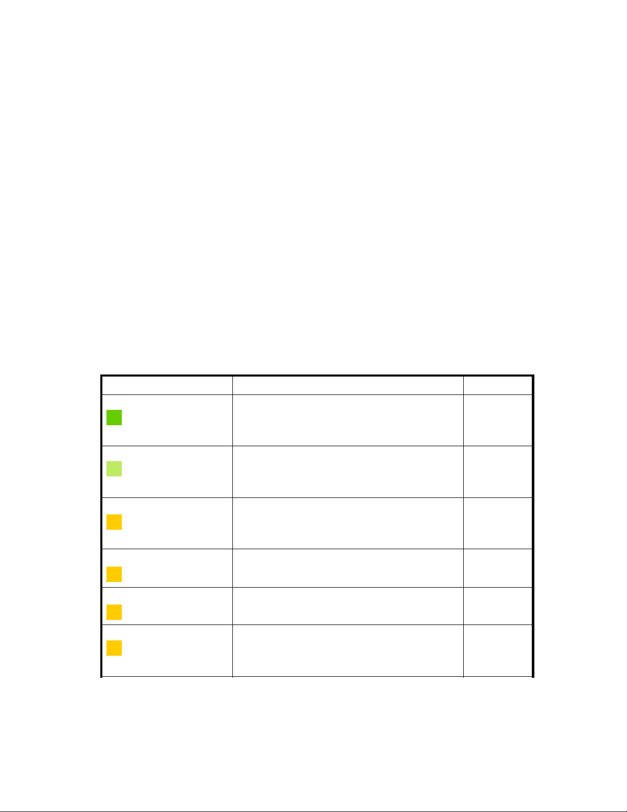
Each smart cell’s life cycle state is color-coded.
•
•
•
•
•
•
•
See "Smart cell life cycle states" on page 25 for more information.
The icon at the beginning of the table row displays the health of the RISS operating system and
applications on the smart cell:
•
•
•
•
TIP:
If you move your mouse over the icon, you will see more information including node status, active thread
count, and the smart cells’s MAC address and IP address.
A green table row indicates a smart cell is ASSIGNED.
AlightgreentablerowindicatessmartcellisCLOSED.
A yellow-orange table row indicates a smart cell is in the COMPLETE_PROCESSING,
SYNC-WAIT, BACKING_UP, or RESTORE state.
A light yellow table row indicates a smart cell is in the DISCOVERY or RESET state.
A red table row indicates a smart cell is SUSPENDED.
A black table row indicates a smart cell is DEAD.
A gray table row indicates the state of a smart cell is UNKNOWN.
A green check icon indicates the smart cell ser ver is started and healthy.
A gray icon indicates that JBoss and the RISS applications have stopped.
A yellow icon indicates that JBoss is running, but one or more RISS applications are unhealthy.
A red X icon indicates that JBoss is running, but one or more RISS applications have failed.
Administrator Guide
29
Page 30

Appliance Stat
istics features
Table 9 Applian
Feature
RISS Appliance The RISS appliance name, IP address, and document storage rate.
Domain
Group Name
Smartcell IP
Smartcell Rol
State
Stored Doc(s)
ce Statistics features
Description
The name of the domain.
A smart-cell group identifier generated automatically by RISS. This
number is unique across all systems.
The IP address of the smart cell.
e
A smart cell ca
Thecurrentlifecyclestateofthesmartcell. See"Smart cell life cycle
states"onpage25.
The number of documents stored since the smart cell was assigned.
nbePrimary,Secondary,Replica-1,orReplica-2.
NOTE:
When the system is actively storing documents, this count might
be different than the stored document count in "Appliance
performance
the smart ce
" on page 28. This number is the real-time count on
ll, while the Appliance Performance count (taken from
the local database) is only updated every minute.
Indexed Doc(s)
Store Rate
Index Rate
The number o
The number of documents being stored per second.
The number of documents being indexed per second.
f documents indexed since the smart cell was assigned.
Index D eletion Queue
Other Smart Cells
RISS Version
Near the bottom of the Overview, you will find information about the RISS system software (also known as
L2) and application software (also known as L3) .
SMTP Flow C
ontrol
At the bottom of the Overview, the SMTP Flow Control area shows the following information, by d omain:
• The maximum number of connections allowed
• The curren
• The number of archiver connections
Storage Status
The Storage Status view provides detailed document storage information for each domain.
The number o
IP addresses of smart cells in the FREE state.
t number of connections
f documents scheduled for deletion.
30 System Status
Page 31

Table 10 Storage Status view features
Feature
Appliance Stor
StoreRateGraph
e
Description
The number of documents and store rate per domain, and the allocated space on
the system for storage and replication.
The dark area on
which storage space is 90 percent full.
the right side of the storage bar graph shows the point at
NOTE:
The storage bar graph shows only assigned and allocated smart cells for
all active domains. The RISS might have fr ee, unallocated hardwar e that is
not represented in the bar graph.
A line graph showing the number of messages per second that the system stored
in the past day, ending with the current time.
Example:
Smart Cell
Allocation
Domain Details
Table 11 Link to Storage Status view
Origin
left menu
System Status
The System Status view provides hardware and system information for all hosts in the system.
The number of smart cells in each life cycle state. (See "Smart cell life cycle
states" on page 25 for an explanation of each state.)
Example:
The domain group ID, the number of documents stored, the amount of used and
total storage space, and the disk/space ratio, shown in bar graph format.
Link
Storage Status
Administrator Guide
31
Page 32

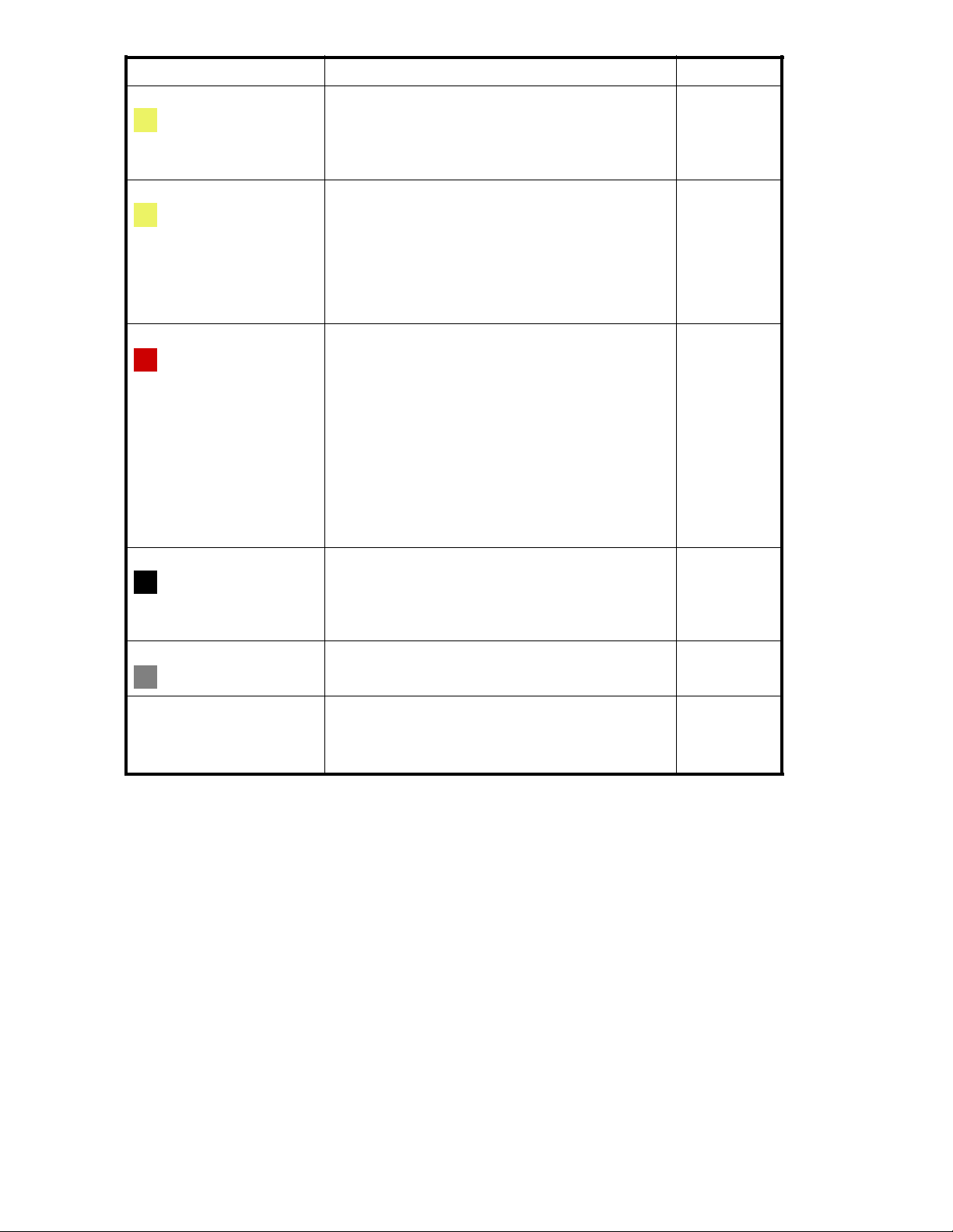
Table 12 System Status view features
Feature
Status
Hostnam
Description
Theiconinfrontofthehostnamedisplaysthestatusofthehostmachine.
•
A green check icon indicates the server is started and healthy.
•
A gray icon indicates that JBoss and the RISS applications on the ser ver
have stopped.
A yellow ico
•
applicatio
A red X icon indicates that the host is either down, or that JBoss is running,
•
but one or more RISS applications on the server have failed.
•
A blue question mark icon indicates that the state of the ser ver is unknown.
e
Thetypeofhostgroup,theserversinthegroup,thefullnameofeachserver,
and the s
Host group types include the following:
• SMARTCELLS Servers: Smart cell servers
• META Servers: Meta servers
• SMTP Servers: SMTP portal servers
• DB Servers: DB2 database servers
• RIM Servers: Email mining servers
• H TTP Servers: HTTP portal servers
• PCC Ser vers: Platform Control Center servers
• KICKSTART Servers: Kickstart servers.
• CLOUDROUTER Servers: Cloud router servers
• LOADBALANCER Servers: Load balancer servers
• FIREWALL Servers: Firewall servers
tatus of each server.
n indicates that JBoss is running, but one or more RISS
ns on the server are unhealthy.
Battery Backed
Write Cache
RAID Controller
Memory
Processor
Used Threads
tery Backed Write Cache support and status for the machine.
Bat
RAID support and status for the machine.
The following messages and status can be displayed:
FAILED:LD1(136GB,RAID1+0,InterimRecoveryMode)
•
REBUILD:LD1(136GB,RAID1+0,Rebuilding1%).(Indicatesadriveis
•
rebuilding.)
•
OK:NoSmartArrayRAIDcontrollertocheck.
OK:LD1(136GB,RAID1+0,OK)
•
The machine’s memory use.
TIP:
If you move your mouse over the entry’s performance bar, you will see more
information including maximum memory (the physical memory available),
total memory (the memory allocated to the RISS applications), and the free
and used memor y (for the memory allocated to the RISS applications).
The machine’s CPU use.
TIP:
If you move your mouse over the entr y’s performance bar, you will see
the actual percentage of CPU use.
The number of threads that are being used by the machine.
32 System Status
Page 33

Table 13 Link to System Status view
Origin
left menu
Link
System Status
Appliance Control
Use the Appliance Control view to start, stop, or restart one or more servers on the system.
This view is useful to show the start, stop, and pending status of a server. However, you should use it only
when necessary — for example, when you are upgrading a host or before a planned power outage. The
Appliance Control view should be used only by system administrators or HP service representatives.
Table 14 Link to Appliance Control view
Origin
left menu
Appliance Control view features
The following information is displayed in the Appliance Control view.
Table 15 Appliance Control view features
Feature
Hostname
Status
Link
Appliance Control
Description
The t ype of host group, the servers in the group, and the full name of each server.
Host group types include the following:
• LOAD BALANCER Servers: Load balancer servers
• CLOUD ROUTER Servers: Cloud router servers
• SMARTCELL Servers: Smart cell servers
• META Servers: Meta servers
• SMTP Servers: SMTP portal servers
• DB Servers: DB2 database servers
• RIM Servers: Email mining servers
• HTTP Servers: HTTP portal servers
• PCC Servers: Platform Control Center servers
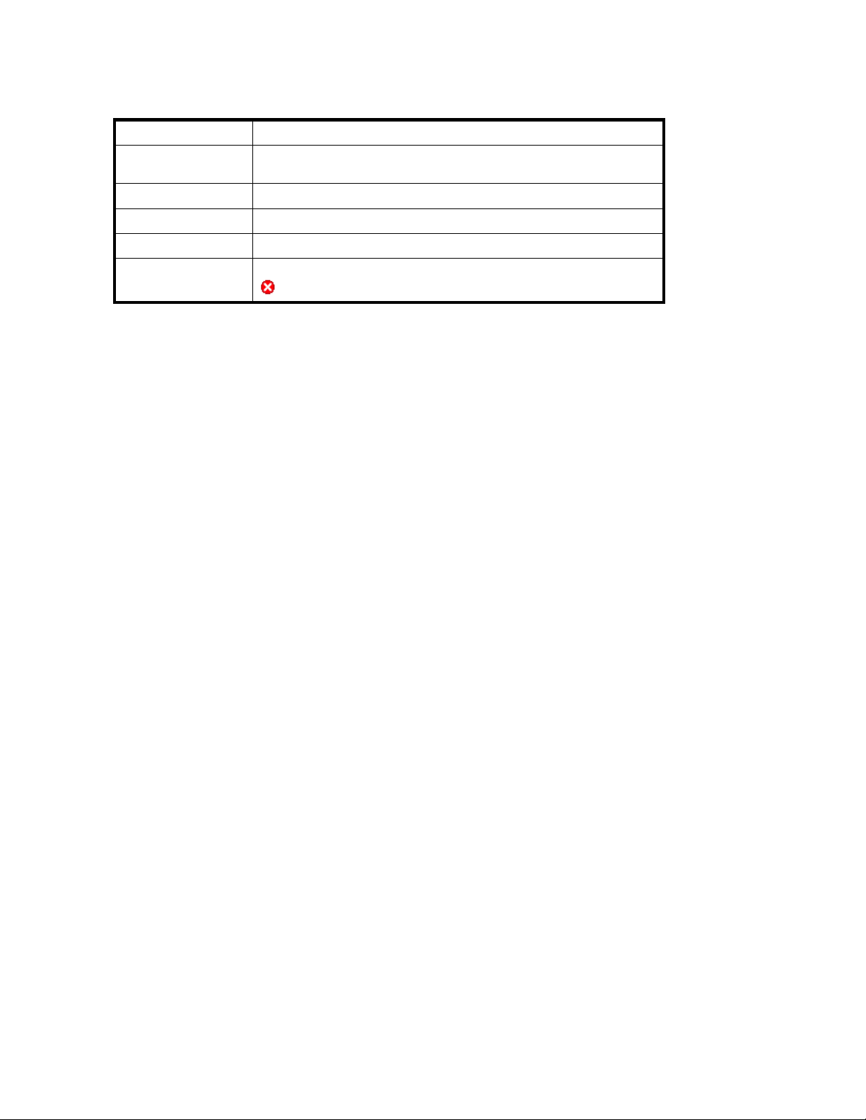
The icon in front of the host name displays the status of the host machine.
•
A green check icon indicates the server is started and healthy.
•
A gray icon indicates the server is stopped.
•
A yellow icon indicates the server is starting or stopping.
•
AredXiconindicatestheserverisdownoranactionhasfailed.
Abluequestionmarkiconindicatesthestateoftheserverisunknown.
•
Host IP Address The host’s IP address.
MAC Address The host’s MAC address.
Other Details Other details about the host.
Starting, stopping, and restarting servers on the system
1. In the Action drop-down list, select the action to perform:
Administrator Guide
33
Page 34

• Start: Start a single machine, start all machines, or start all machines in a selected server
group.
• Stop: Stop a single machine, stop all machines, or stop all machines in a selected server
group.
• Restart: Stop and immediately start a single machine, or stop and immediately start all
machines or all machines in a selected server group.
• Staggered Restart: Restart all machines in sequence, or all server group machines in
sequence, with a minimum of downtime.
NOTE:
StaggeredRestartcanonlybeusedwithsmartcell,HTTP,andmetaservers.
2. Toperformanactiononallmachinesinaservergroup:
a. Click Machine Type.
b. SelectthetypeofserverfromtheMachineTypedrop-downlist.
3. To perform an action o n a particular machine:
a. Click Machine.
b. Select the machine in the Hostname column.
4. Click Run Now!
Performance Graph
Use this view to create graphs showing different types of system events over specified time periods. You
can generate two categories of graphs:
• System monitoring graphs that show idle CPU usage, free memory usage, or the number of
threads used.
• Appliance storage and indexing graphs that show the number of documents stored or indexed on
the system, and the rate at which documents are stored or indexed per second.
Table 16 Performance Graph features
Feature
Heading
Event History
Time
Table 17 Link to Performance Graph view
Origin
left menu Performance Graph
Description
Thetypeofgraphortheservername.
Thegraphedeventhistoryoverthereportedtimeperiod.
Thetimeperiodbeingreported.
Link
Example: Appliance Store graph
An example of an appliance store or indexing performance graph is shown below. This graph charts the
Domain1 store rate for today at five minute intervals.
34
System Status
Page 35

Figure 2 Per
formance Graph: Store Rate
Example: System Monitoring graph
An example of a system monitoring performance graph is shown below. This graph charts the free
memory on the database server at hourly intervals over the past 24 hours.
Figure 3 Performance Graph: Free Memory
Creating performance graphs
1. Click the System Monitoring tab or the Appliance Store and Indexing tab for the category of graph
uwanttocreate.
that yo
2. Select a graph type:
• For System Monitoring, select Idle CPU Usage, Free Memory,orActive Thread Count.
•ForAp
3. Select one of the following options:
•Mach
• Assigned Sm artcell/Domain (Appliance Store and Indexing graphs): Select All Appliance,
4. Selectthetimeframeandreportinginterval:
pliance Store and Indexing, select Store Rate, Ind ex Rate, Object Count,orIndex
Count.
ine Type (System Monitoring graphs): Select the type of machine (for example, PCC
Servers or Smart Cell Servers).
in name,orSmart Cell IP address.
Doma
Administrator Guide
35
Page 36

• Time Frame: For a preselected time period, click Select Time Frame,andselectatimeframe
from the drop-down list.
• From Date, To Date: For a custom time period, click Custom Time Range,andselect
the start date and time and end date and time. The custom time range can be useful for
troubleshooting.
• Interval: Select the reporting interval from the drop-down list.
5. Click Gen erate Graph.
36 System Status
Page 37

4Configuration
This chapter contains the following information:
•
RISS configuration, page 37
•
Firewall Settings, page 38
•
SSL Configuration,page38
• Software Version, page 41
RISS Configuration
The RISS Configuration view is an administrative tool that displays hardware and configuration
information about the RISS.
This view is divided into two parts:
• Informatio
• Information about the RISS system configuration is in the lower portion of the view.
Table 18 Link to RISS Configuration view
n about the services enabled in each doma in is in the upper portion of the view.
Origin
left menu Configuration > RISS Configuration
Link
Domain Configuration
The upper portion of the RISS Configuration view shows information about each domain. It includes the
domain type (Exchange or Domino), the services that are enabled (for example, indexing, replication,
compliance, and data backup), supported document types, and retention period(s).
The domain configuration information is drawn from the Domain.jcml file on the kickstart server.
Figure 4 Domain Configuration
Appliance Configuration
The Appliance Configuration portion of the RISS Configuration view displays the setup details for the RISS
appliance. This information is taken from the BlackBoxConfig.bct file.
Administrator Guide
37
Page 38

Firewall Settin
gs
The Firewall Se
their virtual IP (VIP) addresses.
It includes the following information:
Table 19 Firewa
Feature
Virtual IP The virtual IP address.
Por t
Service
Type
Inbound/Outbound
Table 20 Link t
Origin
left menu Configuration > Firewall Settings
ttings view shows the firewall settings for the PCC server and the RISS HTTP portals, and
ll ports
o Firewall Settings view
SSL Configuration
Description
The port number
The service running on the port.
The transfer protocol used on the port: TCP or UDP
Shows if the fir
and outbound t
ports.
Link
.
ewall is
raffic. Outb ound trafficisnotfiltered on the PCC server
enabled or disabled on the port’s inbound
SSL, or Secure Socket Layer, is a technology that allows web browsers and web servers to communicate
over a secured connection. This means that the data being sent is encrypted by one side, transmitted,
then decrypted by the other side before processing. It is a two-way process, meaning that both the server
AND the browser encrypt all traffic before sending out data.
The SSL Configuration view lets you generate certificate signing requests (CSRs), and corresponding
private keys, for secured connections on the RISS. You can create t wo types of CSRs: one for access to
the PCC portal, and one for access to the HTTP portals.
After generating the CSRs, see "Installing a third party certificate on the PCC portal" on page 40 and
"Installing a third party certificate on the HTTP portals" on page 40 for the steps needed to complete
the process.
The SSL Configuration view contains two areas. The top area shows any current certificate signing
requests in the system. The bot tom area contains a form to com plete to generate a certificate signing
request (CSR) and RSA private key.
Table 21 Link to SSL Configuration view
Origin
left menu Configuration > SSL Configuration
Link
38
Configuration
Page 39

Available certi
ficate signing requests
Table 22 Availa
Feature
Machine Type
Virtual IP
Creation Date
Path
Creating a cer
To create a cer
1. Complete the
You can cre at
the HTTP portal machines.
2. Click Generate CSR.
To install a
portal" on page 40.
To install a certificate on each HTTP portal, see "Installing a third party certificate on the HTTP
portals" on page 40.
ble certificatesigningrequests(CSRs)intheRISSsystem
Description
The host for which the CSR has been generated. The host is either a
PCC or HTTP portal.
The virtual IP a
The date the CSR was created.
The path to the CSR. The CSR files are always placed on the PCC host.
ddress of the host.
tificate signing request
tificate signing request (CSR):
form at the bottom of the SSL Configuration view.
eonlytwotypesofCSRfiles:oneforaccesstothePCC,andoneforaccessto
certificate on the PCC portal, see "Installing a third party certificate on the PCC
NOTE:
If you enter
signing re
incorrect information in the form and need to generate a new CSR, see "Deleting a certificate
quest"onpage39fortheproceduretofollow.
Deleting a certificate signing request
After a certificate signing request (CSR) is generated for the PCC or HTTP portals, it c annot be
regenerated. If you have entered incorrect information in the certificate request, the file must be manually
deleted before you can create a new CSR in the SSL Configuration view.
To delete a CSR:
1. Log in to the PCC console.
2. Go to /opt/keys and delete the CSR with one of the following commands:
rm -f pccCert.pem (to remove the PCC certificate request)
rm -f httpCert.pem (to remove the HTTP certificate request)
3. Upon deleting pccCert.pem and/or httpCert.pem in directory /opt/keys,logofforclosethe
PCC UI. If you do not, refreshing the PCC UI will re-create these files, and the <SSL Configuration>
page will not allow new CSRs be created.
NOTE:
Important! Do not delete the private key files (pcckey.pem or httpkey.pem).
Administrator Guide
39
Page 40

NOTE:
After deleting pccCert.pem or httpCert.pem in /opt/keys,besuretologofforclosethePCC
UI. If you don’t and refresh, the PCC UI will re-create these files. (The SSL Configuration page will
also not allow new CSRs be created.)
Installing and generating a certificate on the PCC portal
Follow these steps to generate and install a certificate for the RISS PCC portal.
1. Create a certificate signing request (CSR) for the PCC:
a. Log in to the PCC Web interface and go Configuration > SSL Configuration.
b. Complete the CSR generation form.
c. Log out of the PCC Web interface.
This generates two files on the PCC:
• /opt/keys/pccCert.pem (the certificate request)
• /opt/keys/pcckey.pem (the RSA private key)
2. Manually copy the certificate request file to your local machine:
scp root@[external ip address of PCC]:/opt/keys/pccCert.pem
3. Send the certificate request to a cer ti ficate authority (CA) such as VeriSign for signing.
Follow the instructions provided by your CA.
4. Import the certificate you receive from the CA into the RISS PCC:
a. Store the certificate from the CA on your local m a chine (for example, as pccCertSigned.pem).
b. Copy the certifica te to the PCC:
scp pccCertSigned.pem root@[external ip address of PCC]:/opt/keys/
pccCertSigned.pem
5. Import the certificate into the PCC’s Apache server:
usr/local/bin/ssl_cert_update.pl -pcc -cert /opt/keys/pccCertSigned.pem
-key /opt/keys/pcckey.pem
6. Restart the PCC’s Apache server by issuing the following command:
/etc/init.d/httpd restart
Installing and generating a certificate on the HTTP portals
Follow these steps to install a certificate on the RISS HTTP portals.
1. Create a certificate signing request (CSR) for the HTTP portals:
a. Log in to the PCC Web interface and go Configuration > SSL Configuration.
b. Complete the CSR generation form.
c. Log out of the PCC Web interface.
This generates two files on the PCC:
• /opt/keys/httpCert.pm (the certificate request)
• /opt/keys/httpkey.pem (the RSA private key)
2. Manually copy the certificate request file to your local machine:
scp root@[external ip address of PCC]:/opt/keys/httpCert.pm
40
Configuration
Page 41

3. Send the certificate request to a certificate authority (CA) such as VeriSign for signing.
Follow the instructions provided by your CA.
4. Import the certificate you receive from the CA into the RISS PCC:
a. Store the certificate from the CA on your local machine (for example, as
httpCertSigned.pem).
b. Copy the certificate to the PCC:
scp httpCertSigned.pem root@[external ip address of PCC]:/opt/keys/
httpCertSigned.pem
5. Import the certificate into the Apache server on each HTTP portal:
usr/local/bin/ssl_cert_update.pl -http -cert /opt/keys/httpCertSigned.pem -key /opt/keys/httpkey.pem
6. From the PCC console, restart all services on the HTTP portal by issuing the following command:
/opt/bin/restarthttp
You can also restart the services using Appliance Control in the PCC Web interface. See "Appliance
Control"onpage33.
Software Version
This view sho
been installed.
Table 23 Software Version view features
ws the software versions that are used by hosts in the system, and any patches that have
Table24LinktoSoftwareVersionview
Displayin
You c a n dis
1. SelectthetypeofhostintheHostTypedrop-downlist.
2. Click Upda
Feature
Base Version
Software Version Third-party software package, also ca lled L3.
Installer Version RISS installation program.
Patches App
Origin
left menu Configuration > Software Versions
lied
Description
RISS and oper
or spine.
History of RISS software patches applied to the system.
Link
ating system software on Linux servers, also called L2
gSoftwareVersion
play the software versions by host type:
To display all software versions of machines in the system, select System as HostType.
te.
Administrator Guide
41
Page 42

42
Configuration
Page 43

5 Accoun t Synchronization
Use this view to confi g ure dynamic account synchronization (DAS), which automatically creates and
updates email user accounts on the RISS, and imports groups and group m emberships. You can define
multiple configurations that track sets of users from one or more LDAP servers for specificRISSdomains.
This chapter contains the following topics for RIM for Exchange administrators. RIM for Domino
administrators will find information on account synchronization (DAS) in their RIM for Domino
Administrator Guide.
•
Account Synchronization overview, page 43
•
Creating and running DAS jobs,page43
•
Editing or deleting jobs, page 47
•
Managing available HTTP portals, page 47
•
Editing or deleting available LDAP connections,page47
•
Viewing DAS history logs, page 48
Table 25 Link to Account Synchroniza tion view
Origin
left menu
Link
User Management > Account Synchronization
Account Synchronization overview
The Account Synchronization view is divided into three sections.
• The DAS
• The LDAP Server Connectors section lists available LDAP connections.
• The Jobs History Logs section shows the history of DAS job runs.
Available Jobs section lists all jobs created and assigned to an HTTP portal.
Creating and running DAS jobs
The basic steps for creating and running a DAS job are as follows:
1.
Create an LDAP connection. See "Creating LDAP server connections" on page 43.
2. Create the job. When you create a new job, you assign the job a name and an LDAP connection,
and set up the job query in the LDAP server. See "Creating jobs" on page 44.
3.
Assign the job to an HTTP portal. See "Assigning HTTP portals" on page 46.
4.
Run the job. See "Running DAS jobs" on page 47.
Creating LDAP server connections
To create an LDAP connection:
1. In
2. Complete the form to create an LDAP service connection by entering the following information:
the LDAP Server Connectors area, click New LDAP.
Administrator Guide
43
Page 44

Figure 5 New L
• Connection Name: Name used to identify the LDAP connection.
• Hostname: IP address of the LDAP server.
•Binderuser
minimum, the user must have read access to all users objects. For example:
cn=Administrator,cn=Users,dc=hostname,dc=com.
•Binderpswd
• Directory Server type: Type of LDAP server to which you are connecting: Microsoft Active
Directory
•SecurityO
• Port: Open LDAP port of the LDAP server. Use the port 389 for simple authentication. Use
port 636 for SSL support.
3. To test th
eLDAPserverconnectionbeforecreatingit,clickLDAP test.
DAP connection
: User in the LDAP directory tree that you want to bind to. At a
: Password of the Binder user.
ption: Type of LDAP security: simple authentication or SSL.
Acontent
bind are successful and the authentication types that are supported by the LDAP server. Errors
are displayed in red.
4. Click Cr
5. Return to the Account Synchronization view and verify that the new LDAP server connection is
listed under LDAP Server Connectors.
Creating jobs
To create a DAS job:
1. In the DAS Available J obs area, click New JOB.
2. Name the job you are creating by entering it in the Job Name box. (In addition to the characters
noted below, the name can contain no spaces.) Click Next Step.
Figure 6 Create DAS job
3. From the drop-down list, select the LDAP connection you want to use with the job.
If you
LDAP s
4. Click Next Step.
pane displays the status of the LDAP connection. It tells you whether the connection and
eate.
need to create the LDAP connection, click Create N ew LDAP Conn e c tion and see "Creating
erver connections" on page 43 for further instructions.
44
Account Synchronization
Page 45

Figure 7 Mappi
5. Complete the form by entering the following:
• LDAP Domain name: Domain to which the users belon g. For example: ldaptest.com.
• LDAPStartingPoint:Rootnodewheretheuseraccountsarestored. Example:
For Exchange, enter cn=Users,dc=ldaptest,dc=com for node Users in domain
ldaptest.com.ThevaluemustspecifytherelativelocationintheLDAPtree,includingparent
nodes a nd domain name. (Another example is ou=stest,dc=sandbox2k_12,dc=com
where ou is the organization name in the exchange.)
• RISS DomainID: The RISS domain ID (not the domain name) where users are synchronized
with users on the LDAP server. This is the same as the domainID set in Domain.jcml.
• Deletion Starting Point: The root node where deleted user objects are stored on the LDAP
server.
Example: For Exchange, enter cn=deletedObjects,dc=ldaptest,dc=com for node
deletedObjects in domain ldaptest.com. Thevaluemustspecifytherelativelocation
in the LDAP tree, including parent nodes and domain name.
6. The console displays “Do you want to attach the job to an HTTP portal” and a
“Back to main page” button.
To complete the advanced options, see "Mapping advanced options" on page 45.
Mapping advanced options
Click the Advanced Options icon ( ) to display the advanced options.
ng information
Figure 8 Advanced options
1. Complete the advanced options form by entering the following information:
• Group Name: Not used at this time.
Administrator Guide
45
Page 46

• USNChanged: ActiveDirectory’suniquesequencenumber(USN).ActiveDirectory
increments the USN for each change in any of its user accounts. When DAS finds a larger
USN, it extracts new information. For initial setup, set USNChanged to 1 so DAS extracts all
users. Thereafter, do not change this value.
• Delete USNChanged: USN in deleted users directory. This is the same as USNChanged but
for deleted objects. For initial setup, set this value to 0. Thereafter, do not change this value.
Thisvaluemustbesetto0thefirsttimethemappingissetup.
• NextRepID: RISS repository ID assigned to new users. DAS retrieves this value from the
database, but you can use this feature to specify the repository ID for the first user inserted
when DAS runs. For example, if you enter 67, the repository created and assigned for
the first imported user is R0000067. You can use this feature if users already exist in the
system or to reserve repository IDs for any reason. If you specify a value that is lower than
an existing repository ID, DAS automatically changes the value to the next higher number.
The default is set to 5.
•AuditRepository:Donotchange.
• Update LDAP filter: Criteria to include or exclude specifi cusers. Forexample:
ForExchange,useatleastthedefault,(objectclass=user)(mail=*),whichexcludesusers
who d o not have email accounts.
• LDAP Query return attributes: List of return attributes. Examples:
For Exchange, use the default attributes unless your LDAP schema requires mapping changes.
• Delete LDAP Filter: Criteria to include or exclude specific users in the LDAP deleted users
directory. Add to the default for special cases.
2. Click Next Step to create the job.
3. To assign this job to an HTTP portal, click Assign Job.
See "Assigning HTTP portals" on page 46 for further instructions.
Assigning HTTP portals
Before running a DAS job, assign an HTTP por tal on which to run the job. Only one job can be
ed to an HTTP portal.
assign
TTP portals are being used, reassign the HTTP portal from another job. (To reassign an HTTP
If all H
portal, select an existing DAS job and click the Unassign HTTP button.)
To assign an HTTP portal to a job:
1. Click
2. Complete the form by entering the following information:
Assign Job.
Figure 9 Assign a job to a portal
• DAS server IP: IP of the DAS HTTP portal where DAS runs the configuration.
•Configuration Enabled: Select Yes to enable. If not enabled, the job cannot be scheduled or
started with this console.
•Configuration running state: Do not change.
• Period: Number of minutes between job runs. Enter 0 to run the job once.
46
Account Synchronization
Page 47

• DAS server running state: Do not change.
3. Click Save.
Starting, sche
1. IntheDASAvailableJobsview,selectthejob.
2. To start the jo
3. To make a chan
4. Click Back to Main Page to return to the DAS view.
TostopaDASjob:
1. In the DAS A
2. Click Back to Main Page to return to the DAS view.
duling, and stopping DAS jobs
b without making changes to the schedule, click Start.
ge to the schedule before star ting the job:
a. Click Sc hedule.
b. Enter the number of minutes between job runs. To run a job once, enter 0.TheDASschedule
should not b
c. Click Confirm Schedule to save your changes.
d. To launch the selected job, click Start.
Anoticeap
A notice appears stating that the job has stopped.
e set to anything less than 60 minutes.
pears stating that the job started successfully.
vailable Jobs view, select the job and click Start/Stop.
Editing or deleting jobs
To edit or delete an active or configured job:
1. In the DAS Available jobs area, click the name of the job you want to edit or delete.
2. To edit the job, click Edit and edit the job mapping.
Click the Advanced Options icon (
for information about job options.
3. To delete the job, click Delete.
) to edit advanced options. See "Creating jobs"onpage44
Managing available HTTP portals
To start, stop, or restart the HTTP p ortals from the Account Synchronization view:
1. In the D
2. Click Assign HTTP Server or Unassign HTTP foraparticularserver.
AS Available Jobs area, click the name of the job.
Editing or deleting available LDAP connections
To edit or delete an LDAP connection:
1. In the LDAP Server Connectors area, click the name of the connection you want to edit or delete.
2. To edit the connection, click Edit, complete the form, and click Save.
3. To delete the connection, click Delete.
Administrator Guide
47
Page 48

Viewing DAS history logs
The DAS jobs history log provides a list of job runs for each configured active job. The log includes the
job name; the number of RISS users that were added, deleted, and updated; the time between job runs;
the job status;
The history also displays the number of RISS groups that were added, deleted, and updated.
To display the histor y log, scroll down to the Jobs History Log area at the bottom of the Account
Synchronization view.
To display a hi
To check the status of a job, view the icon in the State column. For example, the
job is Complete. You can also point to the icon to display the status.
andthedateandtimethejobwascompleted.
story of the previous runs for a specific DAS job, click the job name.
icon indicates the
48
Account Synchronization
Page 49

6AccountManager(AM)
Use the Account Manager (AM) view to provision and update user accounts.
This chapter contains the following topics:
•
AM overview, page 49
• Managing user accounts, page 51
•
Managing groups,page54
•
Managing repositories,page54
Table 26 Link to Account Manager view
Origin
left menu
Account Man
Use Accoun
on the RISS
synchronization with Windows Active Directory.
RISS archives emails and other documents in repositories — virtual collections of documents associated
with a give
Use AM to u
• Add users not imported through dynamic account synchronization (DAS).
• Change user permissions.
• Give user
• Add special-purpose repositories.
• Add or modify routing rules.
• Edit the
NOTE:
You can view accounts on replica domains, but you cannot use AM to add or edit them. Fields cannot be
edited and action buttons are unavailable when you select a domain that is a replica of another domain.
t Manager (AM) to view and update user accounts and repositories for unusual circumstances
. Initial setup, and routine addition and deletion of user accounts, occur automatically through
n user by routing rules (storing) and access lists (retrieving).
retention period for repositories.
Link
User Management > Account Manager
ager overview
pdate accounts as follows:
s access to other repositories.
Administrator Guide
49
Page 50

Figure 10 Account Manager view
The total number of users and groups for the domain(s) is shown in the upper right corner of the view.
50
Account Manager (AM)
Page 51

Account Manager
view features
Table 27 Accoun
Feature
Search button
All check box
A-to-Z buttons Use to display only names starting with the button letter. Names correspond
Panels Select the user, group, or repository radio button to view the corresponding
t Manager view features
Description
Usethesearchfeaturetofind users, groups, or repositories.
The search function uses the “Like” SQL database capability. For example,
in the User panel, you could enter jack to match users jackdoe or jacksmith.
Entering %doe would match users jackdoe, janedoe, or maryjanedoe.
Entering %ja% would match users jadams, jackdoe, janedoe, jacksmith,
or maryjanedoe.
Searches are not case sensitive.
For users and groups, you can search by email account name.
Select this check box to display all objects of the type indicated by filter
name (user, group, or repository). For example, select the User filter and
All to show all users.
to the objects of the current filtered panel.
You can use the search function within the filtered panel.
panel.
• Users (see "Managing user accounts" on page 51) - You can add users,
viewandedituserinformation,changeuserstatusandprivileges,and
remove users from the system.
•
Groups (see "Managing groups"onpage54)-Youcanviewgroup
information.
•
Repositories (see "Managing repositories"onpage54)-Youcan
create repositories and edit repository i nformation. You cannot delete
existing repositories.
Navigation buttons
he navigation buttons at th e bottom of the view to:
Click t
• Add a re
• Addau
• Delet
eauserfromthesystem.
Managing user accounts
Open the Users panel to view, add, remove, or change individual user accounts on the RISS.
Adding a user in Account Manager automatically creates a primary repository for the user. It also
adds routing rules and filters for the user’s contact email address, and gives the user access to his or
her personal repository.
When the RISS system is first installed, a single user (Default) is listed in the Users panel. You can delete
this entry after users are imported into the system.
ing a new user
Add
Toaddanewuser:
1. Click the Add User button at the bottom of the Account Manager view.
2. Complete the RISS Account and LDAP Information form that appears.
e"Editing user information" on page 52 for more details.
Se
3. Click the Save Now! button.
pository.
ser.
Administrator Guide
51
Page 52

Editing user information
To edit user information:
1. Click the User r
See "Account Manager view features" on page 51 for information on searching for a user.
2. In the RISS Account and LDAP Information form that appears, clear the check box labeled Deactivate
this check box and then edit the user entries.
adio button, then click the user name that you want to edit.
Figure 11 Editing user account information
3. Edit the relevant user entries.
4. Click the Save Now! button.
NOTE:
You can change a user’s repository retention period by editing the repository. See "Editing repository
information"onpage55.
52
Account Manager (AM)
Page 53

User account information
Table 28 User account information
Feature
RISS Account
Username
Local Password
First N ame
Last Name
Email Contact
Mail To Me A
Comments
Domain
Mail Server
Information
ddress
Description
(Required.) The system login name for the selected user.
Usernames must be unique, but they can be the same except for their domains. For
example, johnkdoe@company.com could be an Active Directory user imported into
the system through dynamic synchronization (DAS); at the same time, user johnkdoe
could be created as a local user in the RISS.
The password in the RISS system for a selected user. Active Directory users who are
imported into the system through DAS are not required to have a local password.
However, local users must have one.
First name of the selected user.
Last name of the selected user.
(Required.) Email address for the selected user.
(Required.) Email destination when the selected user clicks Mail To Me for an
archived document.
The system administrators’ comments on the selected user account.
(Required.) The RISS domain to which the selected user belongs. Select the domain
from the drop-down list; the selection lim its the scope of the Search and A-to-Z
filter buttons.
The IP add
within Microsoft Outlook is required.)
ress of the mail server for the selected user. (Optional, unless querying
Billing Group ID
Personal Repository
Direct R
LDAP Information
Membership Any groups to which a remote user belongs.
WinDo
LDAP Dn
Source
Object GUID
Object SID
epositories
main
In pre RISS 1.5 systems, this number identifies the account to be billed for services.
It is not used in RISS 1.5.
The ID of the repository created for the selected user.
TheIDsoftherepositoriestowhichtheuserhasaccess.Theuserautomaticallyhas
accesstohisorherownrepository. Iftheuserisamemberofagroup,heorshe
also has automatic access to the group’s primary repository.
You can give the user access to another repository by clicking Edit, selecting the
check b
Repositories (except for the user’s personal repository) can be removed from the list
by selecting the repository name and clicking Remove.
The Windows domain to which a remote user belongs.
The remote user’s object name, relative location in the LDAP tree, and domain. CN
(Common Name) is the object name, cn is its branch in the tree, and dc values are
domain names. DAS supplies this value.
An account synchronization maintained field that indicates which DAS job was
used to create or manage the information.
The G
syn
An identifier for the user, automatically generated and maintained by Active
Directory. (Cannot be edited.)
oxfortherepository,clickingAdd,andthenclickingExit.
lobal Unique Identifier of the user account on the LDAP server. This is account
chronization’s key to the correct account on the LDAP server.
Administrator Guide
53
Page 54

Feature
Description
USNChange
Created Date The date the use
Last Modified Thedatetheuseraccountwaslastmodified.
All Repositories All repositories to which a user has access — either through di rect access or
Proxies
Check boxes
Active/Disabled
RISS Admin Select this c
Compliance
RISS Remote
Authorization
The USN (Active Directory unique sequence number) imported from the
corresponding account on the LDAP server the last time account synchronization
was run.
r account was created.
through group membership.
Displays the e
Select or clear this check box to enable or d isable the user account on the RISS.
It’s best to create a new, local account for the administrator. Be sure to also define
a local password.
Select this check box if the user is authorized to view all recipients (including
BCC addressees) in the repositories to which the user has access. This function is
generally limited to comp liance officers. For a compliance officer to see any BCC
information, either BCC or envelope journaling MUST be enabled on the Exchange
Server and the corresponding setting must be enabled on the email miner. The
system must be running with Compliance archiving, as this feature is not available
with Selective Archiving.
A RISS remote authorization user must be in the system for replication statistics to
be displayed properly in the Replication view. A user account is automatically
created for this purpose, with the username of RISSAuthorizationUser and a
randomly-generated password.
You can change the password for this account. You can also create a new RISS
remote authorization user account and p assword if you want. If you create a new
account, be sure to clear this check box in the RISSAuthorizationUser account, or
delete RISSAuthorizationUser from the system.
mail addresses that will route to the user’s primary repository.
heck box to grant the user administrative privileges on the PCC.
Managing groups
RISS 1.6 do es not support group management in Account Manager.
Manag
Adding repositories
ing repositories
e Repositories panel to change the routing rules or retention periods for a repository, or to add
Use th
itories. You could, for example, add a repository to provide a container for special routings (email
repos
addresses or email domains).
You cannot delete a repository in Account Manager.
To add a repository:
1. Click Add repository.
2. Complete the RISS Repository information form that appears.
See "Editing repository information" on page 55.
3. Click the Save Now! button.
54 Account Manager (AM)
Page 55

Editing repository information
To edit RISS repository information:
1. Click the Respo
2. In the RISS Account and LDAP Information form that appears, clear the check b ox labeled Deactivate
this check box and then edit the user entries.
sitory radio button, then click the repository you want to edit.
Figure 12 Editing repository information
3. Edit the
4. Click the Save Now! button.
relevant entries.
Administrator Guide
55
Page 56

Repository information
Table 29 Repository information
Feature
Name
Domain
Retention
Type
Email routing
Add Email Enter a new
Email Domain Routing The email domain associated with the repository.
Add Email Domain Enter a new email domain to be associated with the repository.
Created Date The date the repository was created.
Last Modified The date the repository was last modified.
Description
(Required.) The name of the selected repository.
The RISS domain to which the selected repository belongs. Select the domain
from the drop-down list; the selection limits the scope of the Search and A-to-Z
filter buttons.
The amount of t
Thetimeperio
Note that quar
Thetypeofrepository:
• Regulated
• Unregulated
• Quarantine
• Other (includes automatically-created repositories for non-indexed documents,
catch-all messages, and audit logs)
Mailing address(es) for email routing. To delete one or more addresses, select the
relevant address(es) in the list, and then select the check box beneath the field.
ime that messages and documents are retained in the repository.
d is shown in days. For example, 2556 days is 7 years.
antine repositories have an infinite retention period.
email routing mailing address.
56
Account Manager (AM)
Page 57

7 Other user m a nagement features
This chapter explains how to use the Manual Account Loader and Error Recovery user management
features.
The chapter contains the following topics:
•ManualAccountLoader,page57
•
Account Error Recovery,page58
Manual Account Loader
Manual Accou
mail server i
(DAS) instead. (See "Account Synchronization" on page 43.)
Do not use this tool with Microsoft Exchange 2000 (or later) servers.
Loading user accounts into the system is a three step process:
1. Export a CSV file containing the user accounts you are loa ding into RISS.
See "Exporting user account information from Exchange" on page 57.
2. Copy the exported CSV file to the PCC server.
3. Load the CS
See "Loading user account information" on page 57.
Table 30 Links to the Manual Account Loader view
nt Loader (MAL) is a batch tool used to load users into the RISS when the Exchange or
s not using LDAP. If the Exchange server is using LDAP, use dynamic account synchronization
V file into RISS.
Origin
left menu
Link
User Management > Manual Account Loader
Exporting user account information
Export user account information by domain. You will need one CSV file for each domain.
To export user account information from an Exchange 5.5 server:
1. Open the E xchange Admin tool.
2. Select Tools > Export Data.
3. Copy the exported CSV file to the PCC server.
Loading user account information
1. Open the Manual Account Loader view in PCC.
2. In the CSV File Uploader box, browse to the CSV file you created in "Exporting user account
information from Exchange" on page 57.
3. Click Upload CSV File.
4. In the Domain Name drop-down list, select the domain associated with the user accounts.
Only one domain can be selected.
5. Click Load Selected File.
Administrator Guide
57
Page 58

The loading process takes about one hour for 50,000 accounts.
6. To verify the results, open the Account Manager.
Error Recovery
TheAccountEr
ror Recovery view displays account synchronization activities that have not been performed
successfully. These activities can include:
• Not being able to add a new user because the user name or object GUID (G lob al Unique
Identifier) already exists
• Not being abl
e to update a user because the user’s entry cannot be found
• Not being able to remove a user because the user’s entry cannot be found
• Not being able to add an alias or email routing rule for a user’s repository
• Not being ab
Activity er
rors are shown grouped by object GUID, with the most recent error at the top of the list. You
le to add a membership to a group
can select an activity to attempt it again, or you can delete it.
Activities can be filtered by clicking User, Group,orMembership at the top of the view.
Table 31 Links to Error Recovery view
Origin
left menu
Link
User Management > Account Error Recovery
Error Recovery features
Table 32 Error Recovery features
Feature
Date
Error
Description
Date the error occurred.
Type of activity error. For example, not being able to add an alias or email routing
rule for a user’s repository.
USN
UserName
GroupName
Group
Member
MemberType
Object GUID
LDAP DN
Active Directory unique sequence num ber. (User and Group filters only.)
The name of the user account. (User fi lter only.)
The name of the group account. (Group filter only.)
Automatically generated identifier for the selected group; unique to the system.
(Membership filter only.)
The name of the repository. (Membership filter only.)
Thetypeofrepository:
• Regulated
• Unregulated
• Quarantine
• Other (includes automatically-generated repositories for non-indexed documents,
catch-all messages, and audit logs)
(Membership filter only.)
TheGlobalUniqueIdentifier of the user account on the LDAP server; its
corresponding object name, relative location in the LDAP tree, and domain. CN
(Common Name) is the object name, cn is its branch in the tree, and dc values are
domain names. Account synchronization (DAS) supplies these values.
(User and Group filters only.)
58
Otherusermanagementfeatures
Page 59

Repairing synchronization errors
To repair synchronization activity errors, identify the activities tha t you want to reattempt or delete. Click
an entry to disp
(UMS) databas
You will need to decide the order in which to reattempt or delete the activities.
To repair or delete synchronization errors:
1. Identify the a
You can click the entry in the UserName or G roupName column to find out more about the error.
2. Click Apply Selected.
If the reattem
3. Identify the activities that you want to delete and select the check box in front of those entries.
You can click the entry in the UserName or G roupName column to find out more about the error.
4. Click Delete
When an activity is deleted, it is immediately removed from the list and cannot be recovered.
lay more information about an activity, including its Java User Management Services
e entr y (only shown if a UMS database entry matches the activity).
ctivities that you want to reattempt and select the check box in front of those entries.
pt is successful, the entry is removed from the list.
Selected.
Administrator Guide
59
Page 60

60
Other user management features
Page 61

8 Data management
This chapter discusses the following topics:
•
Replication, page 61
•
Smartcell Cloning, page 64
•
Reprocessing , page 66
•
Repository level retention, page 68
•
Database and data backup, page 70
Replicatio
NOTE:
This view is available only if a replicated system is configured.
Use the Replication view to monitor and to start or stop replication for a domain on a remote system.
Replication status is updated after each polling cycle. Therefore, it could be up to five minutes after you
start replication before you see results on the graph of replication rates. Errors and warnings, however,
are displayed as soon as they happen on the system. (The Replication view is unavailable until at least
one dom ain on the PCC host system is configured for replication.)
A failed replicated smart cell triggers allocation of new primary and secondary smart cells on the replica
site. When the original site returns to service, it automatically becomes the replica site for new primary
and secondar y smart cells. Depending on configuration, some administration might be necessary for
continued data storage. Specifically, if the system uses Selective Archiving, the replica site mining servers
must be configured and enabled to start mining to the replica site.
If the primary site is not available for queries, users must enter the address of the replica s ite, instead
of the primary site, in their browsers.
NOTE:
In order for the Replication view to display statistics from the remote system, a RISS remote authorization
user must be set up in Account Manager. See RISS Remote Authorization in "User account
information"onpage53.
n
Table 33 Link to Replication view
Origin
left menu
Database Replication
IMPORTANT:
When installing a replica RISS, finish db2 replication before starting JBoss on all other servers, otherwise
some RISS applications will not be able to access db2 because db 2 tables are locked by the db2
replication process.
Link
Data Management > Replication
Administrator Guide
61
Page 62

The top part of the Replication view describes the database replication.
Table 34 Database Replication features
Feature
Local Server/Source
Server
Local Server/Target
Server
Replication Set
Inbound Sync
Time/Outbound Sync
Time
Inbound Sta
Outbound St
tus/
atus
Description
The replication and primary systems if you are logged into the replicated
system.
The primary and replication systems if you are logged into the primary
system.
A set is made of one or more db2 tables that replicated.
The time at which the database tables in the replication set got last
synchronized. The synchronization time is displayed in two colors: green
and red. Green means that the database tables on the primary and
replica DB2 have been synchronized successfully within the last 30
minutes. Red means that the synchronization has not happened for 30
minutes or more; this could indicate a db2 replication issue and you
should contact HP technical support for advice.
The replication status on the replicated and primary systems.
(Re-)Initializing db2 replication
Follow the steps below to initialize or re-initialize db2 replication:
1. Stop the RISS applications on the primary and replica:
PCC on primary: /opt/bin/stop
PCC on replica: /opt/bin/stop
2. Unconfigure db 2 replication on primary/replica:
DB2 on replica: /opt/bin/repl/dbRepl rm
DB2 on primary: /opt/bin/repl/dbRepl rm
3. Restart db2 on primary/replica:
DB2 on primary: /etc/init.d/db2_app start
DB2 on replica: /etc/init.d/db2_app start
4. Re-initialize db2 replication on primary/replica:
DB2 on primary: /opt/bin/repl/dbRepl init
DB2 on replica: /opt/bin/repl/dbRepl init
5. Wait for the replication process to comp lete (this can take anywhere between a few minutes to an
hour or more depending on the size of the db2 database and the bandwith of the network between
the two RISSes):
DB2 on replica: /opt/bin/repl/dbRepl status -brief -force
Look for the message "Replication is active." Re-issue the command every few minutes until this message
is returned, or while you see the message Refresh is in-progress.
6. Once replication is successfully initialized, restart the applications on primary/replica:
PCC on primary: /opt/bin/start
PCC on replica: /opt/bin/start
Data management
62
Page 63

Replication Sta
The middle part of the Replication view displays the status of the replication.
Table 35 Replic
tus
ation Service Gen eral Status
Feature
Domain
State
File Batch Count
Update Time
Next Retry Time
Message
Remote Authorization
Service
Data Replica
The bottom part of the Replication view displays the flow of replicated data. You can also suspend
or resume the
Table 36 Data Replication Flow
Feature
Domain
Description
The domain name and group ID of the domain being replicated.
Shows whether or not replication is in progress.
The number of batches being replicated.
The time of the last replication update.
The date and time of the next replication update.
Any messages about the last replication update.
Shows if the RISS remote authorization user has been set up in Account
Manager.
This user must be set up in the system for the Replication view to display
statistics from the remote system. See RISS Remote Authorization in "User
account information"onpage53.
tion Flow
replication process from this area.
Descriptio
The domain name and group ID of the domain being replicated, and the following
information:
• The IP addresses of the smart cells being duplicated, the status of the replication,
and the number of stored and indexed documents being copied.
n
A check icon indicates normal operation.
An X icon indicates that replication failed the last time it was tried.
An ! icon indicates replication is being retried.
• An arrow showing the direction of data. Normally, the direction is left to right,
from the primary system to the replicated system. In a failover situation, the
direction is right to left, as the data replicated on the replicated system is being
used to restore the group on the primary system.
• The number of stored and indexed documents that have been copied to the
replicated domain.
• The percentage of data that has been copied to the replicated domain.
Suspend/Resume To stop replication, click Suspend. Replication will stop after the current batch
is replicated.
To start replication, click Resume. The batch that would have been replicated next
when replication stopped will be replicated.
Administrator Guide
63
Page 64

Smart cell cloni
ng
Use the Cloning
You can clo n e a s
life cycle states" on page 25.)
Cloning a smart cell copies all its information to another smart cell that is in the FREE state to give the
smart cell a new, viable mirror. Cloning operations can take a long time (as much as a day), depending
on the amount of information cloned.
To place a sour
When you acces
data. Only on
operation.
Table 37 Link to Cloning view
Origin
left menu
view to show the status of current and past cloning operations, and to clone a smar t cell.
mart cell if its mirror smart cell is SUSPENDED, DEAD, or FAILED. (See "Smart cell
ce smart cell in the free pool, use the /opt/bin/start_reset.sh script.
s the Cloning view, PCC searches for ongoing cloning operations and loads the current
e smart cell can be cloned at a time, so you see the progress of any ongoing cloning
Link
Data Management > Cloning
Data management
64
Page 65

Cloning view fea
tures
Table 38 C lonin
Feature
Source
Free Cell
Assigned/Free A graphical representation of the assigned and free smart cells.
CloneCell Startsthecloningoperation.See"Cloning smart cells (copying data)"onpage65.
Cloning Area
History Logs
s
gviewfeatures
Description
The IP address of a smart cell without a viable mirror. If all smart cells have viable
mirrors, the Source displays No Broken Groups Found. If more th an one smart
cell needs a mirror, a Change Source button appears below the automatically
selected IP address.
The number of smart cells currently in the F REE state. This number is decreased
by one after a cloning operation starts.
This are
• Source s
• Target
• Curren
• Overa
Some steps happen so quickly you might not see them.
St
there is a great deal of data to clone.
The following in formation about each cloning operation that has occurred since
startup:
• Source
• Target
• Time Elapsed
• Status
• Date
a provides the following information about an ongoing cloning operation:
elected: IP address of the smart cell being duplicated.
selected: IP address of the smart cell receiving duplicate data.
t Step Percentage: Dynamic bar showing how much source data has
been du
Cloning operation steps are as follows:
•Initializing
• Assigning target host
•Transferringdata
•Transferringindexes
• Waiting for indexer to complete
• Updating history log
• Completed or Failed
epssuchasTransferringdataandTransferringindexescantakealongtimeif
plicated.
ll Percentage: Current step in the cloning operation.
Cloning smart cells (copying data)
To clone a smart cell:
1. Perform one of the following actions:
• Select the sma rt cell from the Source field.
• If the option is present, click Change Source to select a different smart cell for cloning. When
the selection box appears, select the s mart cell you want from the drop-down list, and click
Select.
2. Click Clone Cell.
This button is unavailable if there are no smart cells to clone.
When cloning is s uccessful a pop-up panel appears on the PCC.
Administrator Guide
65
Page 66

3. Check the Status Area to see results of the cloning operation.
A check icon indicates the cloning operation is proceeding normally.
An X icon appears if the cloning operation has failed.
Reprocessing
The Reprocessing view displays each domain and shows whether reprocessing is enabled, when
reprocessing
stored data and reallocates messages to the proper repository.
Most reprocessing occurs as an automated and transparent background process that does not require
any operational effort other than passive monitoring.
In most cases,
are applied t
to schedule and enable reprocessing based on new routing rules.
NOTE:
When you make a change using the Reprocessing Utility, the change does not take place immediately. It
is put in the job queue, and the reprocessing itself occurs 24 hours later.
Table 39 Link to Reprocessing view
is scheduled, and a history log report. Reprocessing is an engine service that scans recently
messages are reprocessed to reapply routing rules that have been recently added and
oashorttimeperiodbeforethechangehasoccurred. TheReprocessingviewallowsyou
Origin
left menu
Link
Data Management > Reprocessing
Rescheduling all reprocessing schedules
To reschedule all the domains to the same reprocessing schedule:
1. In the Reprocessing view, click Reschedule All.
2. Complete the form to set the status and schedule.
3. Click Reschedule All.
4. To ensure that all schedules are enabled, verify that all Reprocessing Status check boxes are selected.
If selected, the text Enabled appears next to the check box.
Editing reprocessing schedules
To edit a domain’s reprocessing schedule:
1. In the Reprocessing view, click the edit link next to the domain you want to edit.
Figure 13 Editing reprocessing schedules
2. Complete the form to set the status and schedule.
3. Click Save Schedule.
Data management
66
Page 67

4. To ensure the schedule is enabled, verify that the corresponding Reprocessing Status check box
is selected.
If selected, the text Enabled appears next to the check box.
Changing the reprocessing status
You can enable or disable a reprocessing schedule of a specific domain or all the domains listed.
To change a reprocessing schedule:
1. In the Reproce
ssing view, locate the domain whose schedule you want to enable or disable.
2. Complete any o
Figure 14 Change the reprocessing status
• To enable reprocessing for a specific domain, select the corresponding Reprocessing Status
check box.
•Todisablereprocessingforaspecific domain, clear the corresponding Reprocessing Status
check box.
• To enable reprocessing for all domains, click Resume All.
• To disable reprocessing for all domains, click Su spend All.
3. Verify the status by noting the text Disabled or Enabled next to the Reprocessing Status check box.
f the following tasks to change the status:
Using the Reprocessing Utility
You can reprocess a user repository if you think a user hasn’t been included in the processing.
In the Reprocessing Utility area of the view:
Figure 15 Reprocessing utility
1. Enter the following information in the text boxes:
• The user email address
• The user repository ID
Users can only be reprocessed if their email address and repository are in the RISS system. If so,
they are listed in the Account Manager.
2. In the Domain Name drop-down list, select the domain in which the user repository resides.
3. Specify a date range, and click Add in Reprocessing Queue.
The job is sent to the queue, and the reprocessing takes place 24 hours later.
Administrator Guide
67
Page 68

Viewing reproce
ssing history logs
The reprocessi
reprocessing r
was reprocess
groups, which is averaged from the individual smart cells of each group.
ng history log at the bottom of the Reprocessing view shows a list of the last successful
uns for each configured domain. The log includes each domain group, when a domain
ed last, and the number of processed files. This report is based on data from smart cell
Repository-level retention
RISS archives emails and other documents in one or more repositories. A repository is a virtual collection
of documents associated with a given user by routing rules (storing) and access control lists (ACLs)
(retrieving).
You can use the Retention view to configure document retention periods for domains and repositories. For
example, you can remove expired stored data or remove access to stored data for specific repositories
based on user-defined retention policies. When the retention rules locate expired data, references to
the data are removed from the index. The data itself is removed from the file system after all references
to it have been removed. This is useful in meeting compliance requirements, when your company must
retain all emails for a specified number of years.
In addition to a history log report, the Retention view displays a domain’s retention period and status.
Each repository within the domain also has a retention period. If the domain’s retention period is greater
than a specific repository’s retention p eriod, the domain’s retention period is applied to that repository.
Otherwise, the repository’s retention period is applied.
NOTE:
Quarantine repositories are the exception to this rule because they have an infinite retention period.
Table 40 Link to Retention view
Origin
left menu
Link
Data Management > Retention
Searching for and editing a repository retention period
Changes to user repository retention periods are handled by the Account Manager. You can change the
retention period in the Account Manager, or you can edit the same form from the Retention view.
To search for a specific repository and change its retention period in the Retention view:
1. Enter all or part of the user name in the Edit User Repositories box and click Search.
The search function uses the “Like” SQL database capability. For example, you could enter jack
to match users jackdoe or jacksmith. Entering %doe would match users jackdoe, janedoe,
or maryjanedoe. Entering %ja% would match users jadams, jackdoe, janedoe, jacksmith, or
maryjanedoe.
Searches are not case sensitive.
2. If necessary, click one of the repository tabs (Regulated, Unregulated, Quarantine, Other) to
locate the repository.
3. Click the repository name to edit its retention period.
Data management
68
Page 69

Figure 16 User Repository search results
4. In the form that appears, clear the check box at the bottom of the form.
Figure 1
5. Change the retention period in the Retention text box.
Retention periods are shown in days.
6. Click Sa
NOTE:
You can view user repositories on replica domains, but you cannot edit them. Retention periods and
other fields cannot be edited and action buttons are unavailable when you select a domain that is a
aofanotherdomain.
replic
7 Edit repository retention period
ve Now!.
Editing domain retention periods
To view or edit a domain’s retention period:
1. In the Retention view, click Edit next to the domain you want to view or edit.
2. Set a new retention period by selecting a preset time period from the drop-down list, or by entering a
specific time period in the text box.
Administrator Guide
69
Page 70

Figure 18 Edit domain rete ntion period
3. Click Save Retention Now!.
4. To ensure that retention is enabled, verify that the domain’s Retention Status check b ox is selected.
If selected, the text Enabled appears next to the check box.
Changing th
e retention processing status
You can ena
To change the retention processing status:
1. Locate the d o m ain whose retention processing you want to enable or disable.
2. Complete any of the following tasks to change the status:
•Toenable
• To disable retention processing for a specific domain, clear the corresponding Retention
• To enable retention processing for all domains, click Resume All.
• To disable retention processing for all domains, click Suspend All.
3. Verify the status by noting the text Disabled or Enabled next to the Retention Status check box.
ble or disable retention processing for a specific domain or all the RISS domains.
retention processing for a specific domain, select the corresponding Retention
Status check box.
Status ch
eck box.
Viewing retention history logs
The Statistics and Logs area at the bottom of the Retention view shows the last data optimization runs
for each configured domain. The log includes each domain group, when a domain was reprocessed
last, and file activity.
Datab
ase and data backup
DB2 da
view s
tape backup if it is enabled.
tabase files and the master configuration files are backed up automatically every night. This
hows the status of the last two local backups, the last backup to the kickstart server, a nd the
Data management
70
Page 71

Table 41 DB Backup History
Feature
Backup Status
Configuration
Information
RISS Backup Events
Table 42 Link to DB and Data Backup view
Origin
left menu
Backup file locations
• Database backup files: The database backup files and DB2 transaction log files are stored on
the database server (partition: /db2/VolBack). The files are mirrored to a directory on the
kickstart machine (/install/db2backups). Database files are backed up once a day, and
the local backups are kept for two days before they are deleted.
• Master configuration files: There are three master configuration files: BlackBoxConfig.jcml,
Domain.jcml,andtheUserKeyStore file in the /install/configs/primary directory
on the kickstart server. Whenever one of these files is changed a nd the converter and
Registry Loader are run, the changed files are copied to the PCC machine, to the directory
/usr/local/MasterConfigFiles.
(To run the RegistryLoader script after changing a configuration file, run the following script on the
kickstart ser ver: regloader.pl -cv.)
Description
General status of the backup server and each of its services.
•
A check icon indicates normal operation.
A ! icon indicates a problem or inactive service.
•
Configuration information such as backup service (enabled or disabled),
job schedule
Information about the backup.
(time) database backup file path location, Tivoli version.
Link
Data Management > DB and Data backup
NOTE:
The file BlackBoxConfig.bct is not included in the backup, because it can be generated
from BlackBoxConfig.jcml (/install/tools/converter/dumpBCT). The script
createBBC.zr generates the .jcml versionthatisthenbackedup.
If the backup server is installed and application backup (APP) is enabled in the BlackBoxConfig.bct
file, the database backup fi les and copies of the master configuration files are also backed up to tape.
Restoring DB2 and master configuration file backups
The D B2 database can be restored from the backup files on the /db2/VolBack partition on the
database server. When data is lost because the database machine was reinstalled, restore the backup
files first. Restore the backup files from either the copy on the kickstart server, or tape backups if
application backup is enabled.
The functionality to restore the database backup par tition and the database itself is implemented in the
script: /opt/bin/backup/db2BackupUtility on the database server. Obtain detailed usage
information by running the command without any arguments.
Follow these steps to restore the database:
1. Before restoring the database, stop all RISS applications by issuing /opt/bin/stop on the PCC
server.
2. Log on to the database system.
Administrator Guide
71
Page 72

3. If the database server was reinstalled, run one of the following commands to restore the
/db2/VolBack partition from either the version stored on the kickstart server or tape backups.
NOTE:
This will delete the content of the VolBack directory.
/opt/bin/backup/db2BackupUtility -restore_from_kickstart
•
/opt/bin/backup/db2BackupUtility -restore_from_tape
•
4. To restore the database, make sure the database is up by issuing the command:
su – db2udb –c db2start
5. To restore DB2, run the following comm and. It will ask for a timestamp of a backup to restore.
Normally, the last two backups of the database are kept.
/opt/bin/backup/db2BackupUtility -restore_db2
6. After the installation is finished, run /opt/bin/start on the PCC server to start the RISS system
and validate that it operates correctly.
Restoring the master configuration files
Copies of the master configuration files are kept in the /usr/local/MasterConfigFiles
directory on the PCC server. Whenever one of the files is changed on the kickstart server and
the converter is run, the master configuration file is copied to the PCC server, and renamed to
YYYY-MM-DD-hh.mm.ss_FileName. It is also backed up to tape, if application backup is enabled.
To restore this directory from the tape backup, run the following command on the PCC server:
/usr/local/tsmBackup/rotateMasterConfigBackup –restore
Data management
72
Page 73

9Reporting
This chapter includes information about the following topics:
•
Event Viewer,page73
•
SNMP Management, page 74
•
Email Reporter,page76
•LogFileSender, page 77
Event Viewer
The Event Viewer shows the critical and recovery events that have occurred in system services or
applications. You can also use the Event Viewer to search for events by type.
The followin
g information is displayed in the Event Viewer.
Table 43 Even
Feature
Event
Machine Type
IP Address
Date
Level
Table 44 Links to Event Viewer
Origin
left menu
left menu
tViewerfeatures
Description
Information describing the event, including the service or application
name.
Thetypeofserveronwhichtheeventoccurred.
TheIPaddressofthemachineonwhichtheeventoccurred.
The date and time of the event.
Status of the event:
•
•
Link
Reporting > Event Viewer
Select Overview,andthenclickMore Details in Application Events
Searching the Event Viewer
Critical
Recovery (Recovery represents a transition from a critical status
value to the normal status value.)
To search the Event Viewer:
1. SelectaSearchTypeinthedrop-downlist.
You can choose from the following types of searches:
• Show All Alerts
•ErrorLevel
•HostName
•ClassName
• Machine Type
2. In the Search Criteria text box, enter the criteria for the search.
Administrator Guide
73
Page 74

You must enter criteria for all searches except Show All Alerts.
The search function uses the “Like” SQL database capability. For example, you could enter sc to
match host names sc-s1-172-1.company.com or sc-s2-204-1.company.com. Entering %204% would
match hosts sc-s2-204-1.company.com, or ms-s0-204-1.company.com.
Searches are not case sensitive.
3. Click Submit.
Other Event Viewer features
You can change the number of events displayed on each Event Viewer page by following these steps:
1. Go to the Events Per Page drop-down list in the bottom right corner of the view.
2. Select the number of events to show on the page, and click First.
You can delete events from the Event Viewer by following these steps:
1. Select an event or go to the time period drop-down list in the bottom left corner of the view.
2. Click Delete in the bottom left corner of the view.
SNMP Management
Use the SNMP Mana gement view to perform the following actions:
• Download the RISS MIB.
• Set the SNMP monitoring management server.
• Select SNMP traps for monitoring.
• Receive SNMP events via email.
• Set SNMP community.
Table 45 Links to SNMP Management view
Origin
left menu
Link
Reporting > SNMP Management
Downloading the RISS MIB
The RISS MIB (management information base) allows monitoring app lications such as HP OpenView to
recognize SNMP events coming from the RISS system.
In the MIB Manager Service area, click the Download button to copy the RISS MIB file to your local
machine. To import the MIB, refer to the documentation for your monitoring management software.
Setting the SNMP server
In the SNMP Server Monitors area, enter the IP address of the monitoring management server, then
click Add Server.
You can enter more than one IP address, since the SNMP information can be broadcast to multiple
servers, or receivers.
NOTE:
Always enter the IP address of the server; do not enter the hostname.
Use of a server can be enabled or disabled by clicking the radio button in front of the server entry,
then clicking Toggle Enabled/Disabled.
74
Reporting
Page 75

A server can be deleted from the list by clicking the radio button in front of the server entry, then
clicking Delete Server.
NOTE:
If you do not have a monitoring management server, you can receive SNMP event notifications via email.
See "Receiving SNMP events by email"onpage76.
Selecting SNMP t raps
In the Trap Manager Service area, select the SNMP events, or traps, to be monitored. When one of the
traps fails, a notification is sent to the SNMP monitoring management server and/or email recipient.
To set the SNMP traps:
1. Select the system for which the traps will be activated.
2. Select the traps to be activated, and click Set Traps.
Thefollowingtrapscanbeactivated:
• smartcell_dead: A smart cell has failed. This trap is generated when a smartcell in the
RISS system goes in the dead state.
• reprocessing_trap: Reprocessing has failed. This trap is generated when the reprocessing
service encounters a problem during execution.
• retention_trap: Retention has failed. This trap is generated when the retention service
encounters a problem during execution.
• quarantine_trap: One or more quarantine repositories has failed. This trap is generated
when the quarantine service encou nters a p roblem during execution.
• raidstatus_trap: There is a disk hardware failure. This trap indicates an abnormal condition
on a RISS server’s RAID controller.
• bbwcstatus_trap: This trap indicates an abnormal condition on a RAID controller’s
battery-backed write cache.
• smartcell_suspend: A smart cell is in the suspended state and cannot store data. This trap
indicates that a suspend event has been sent to the SC.
• smartcell_unsuspend: This trap indicates that an unsuspend event has been sent to the SC.
• smartcell_assign: This trap indicates that an assign event has been sent to the SC.
• smartcell_assign_space: This trap indicates that an assign_space event has been sent
to the SC.
• smartcell_assign_restore: This trap indicates that an assign_restore (cloning) event has been
sent to the SC.
• smartcell_found: This trap ind icates that a previously lost SC has been started. An attempt
will be made to recover it.
• smartcell_lost: This trap indicates that an SC has been shutdown or stopped. Its pair will
be suspended.
• pingFailure: This trap indicates that a specific host has stopped responding to the ping
service. The ping service down m eans either the machine is getting rebooted or there is a
network failure. If a reboot has not been issued by the administrator then there is problem
with the machine.
• partition_full: This trap indicates that one partition has reached a certain critical usage.
• fs_full_trap: A filesystem on a RISS system has reached 99% full.
• machine_unresponsive: The RISS OS and applications on a machine are down. Cannot
ping the machine.
• Assign_space: A trap that is sent when a smartcell group has run out of room and a new
smartcell group needs to be assigned.
Administrator Guide
75
Page 76

Receiving SNMP e
ventsbyemail
If you do not hav
option is also u
To enable the ser vice, enter your email address or the email address of the person who will receive the
notifications, and click Add.
Repeat this ste
You c an disable or delete an email recipient by clicking the radio button in front of the person’s name,
then clicking Disable or Del ete .
NOTE:
The mail host’s
sent. See "Detailed email reports" on page 76 for more information.
e a monitoring management server, you can receive SNMP notifications via email. This
seful if you are away from the office.
p if you want to add more recipients.
IP address must be entered in the Em ail Reports view for SNMP email notifications to be
Setting SNMP Community
An SNMP community string is a text string that acts as a password. It is used to authenticate messages
that are sent between the management station (the SNMP manager) and the device (the SNMP agent).
The community string is included in every packet that is transmitted between the SNMP manager and
the SNMP agent.
Email Reporter
Use the Email Reporter to configure summary monitoring reports that are sent periodically to your chosen
email recipients.
You can select the information to be sent and the frequency of the reports— from every 2 hours to every
24 hours. These reports can include system status, storage rates, node health, and other information from
the PCC views.
Table 46 Links to Em ail Reporter view
Origin
left menu
Link
Reporting > Email Reporter
Detailed email reports
The following information is provided in detailed email reports.
76
Reporting
Page 77

Table 47 Detailed Email Reports
Feature
VERSION
EMAILMINER_
METRICS
DAS_STATS
NODE_HEALTH
EVENTS
SMARTCELL_METRICS
CONFIG
CORE
Description
Provides information about the RISS software version from the Overview.
See "RISS Version"onpage30.
Provides statistics collected by RIM for Messaging. See "Mining
Overview"onpage79.
Provides user account information from the Account Manager Service
section of the Overview. See "Account Manager Service" on page 28.
Also provides names of the scheduled account synchronization (DAS)
jobs.
Provides host status and other information from the Appliance Control
view. See "Appliance Control"onpage33.
Provides information on current critical events from the Application Events
section of the Overview. See "Application Events"onpage27.
Provides smart cell information from the Appliance Statistics section of
theOverview. See"Appliance Statistics"onpage29.
Provides domain configuration information from the RISS Configuration
view. See "Domain Configuration"onpage37.
Provides storage information from the Appliance Performance section of
theOverview.See"Appliance performance"onpage28.
Creating and scheduling email reports
1. Select one of the following:
• Default Selection to send all information listed in Features.
NOTE:
Always use the Default Selection when you are sending emails to HP technical support.
• Custom Selection to pick specific information to send.
2. Enter one or more email addresses in the Recipient text box.
When entering several email addresses in the box, separate them with a comma or semicolon. For
example: recipient1@mycompany.com,recipient2@mycompany.com.
3. In Features, select the information to be sent.
This function is only available if you have made a custom selection.
4. In the Frequency drop-down list, select the frequency that the report should be sent.
The frequency ranges from two hours to 24 hours.
5. Click the maximize box in More Details and enter the email address of the report’s sender.
6. If this is the first time you are using email reports, enter the IP address of the mail host.
7. Click Schedule.
The Email Report information appears in the Current Active Schedules portion of the view. If you want to
delete a recipient, select the recipient, then click Delete.
Logfile Sender
The Logfile Sender view lets you select log files to email. For example, you would send log files to
HP technical support to assist in troubleshooting.
Administrator Guide
77
Page 78

Tosendalogfile:
1. Enter the recipient’s email address in the Email Address field.
You can enter only one email address.
2. Select a log file to send.
You can select only one log file to send.
3. Click Collect Logs Now!
Table 48 Links to LogFile Sender view
Origin
left menu Reporting > Logfile Sender
Link
78
Reporting
Page 79

10 External access
The PCC left menu contains a link to an external function that is not managed within the PCC:
•
"RIM Management" on page 79, which accesses the Reference Information Manager (RIM)
email mining system
RIM Management
This view provides an entry point to the email mining system. It also displays an overview showing the
mining system status for each domain.
For information on the mining overview, see "Mining Overview"onpage79.
To access the
email mining system:
1. In the left m
The VNC Viewer: Connection D etails dialog box appears.
2. Click OK.
The VNC Auth
3. Enter the password that was provided by your HP service representative, and press Enter.
The Windows Welcome screen appears.
4. Place your m
select Send Ctrl-Alt-Del to display the Windows login screen.
You can also call the Windows login screen by pressing Shift+Ctrl+Alt+Delete or AltGr+Delete.
5. LogintoVNCusingthepasswordprovidedbyHP.
NOTE:
Important! Do not use Ctrl+Alt+Delete. This key sequence does not work when logging
in to VNC from the PCC.
Table 49 Link to RIM Management view
Origin
left menu
enu, go to RIM Management and select VNC Miner[1].
entication dialog box appears.
ouse cursor anywhere in the VNC viewer and press F8. In the menu that is displayed,
Link
RIM Management
Mining Overview
This view provides information about the mining system for each domain, including service status and
health.
Administrator Guide
79
Page 80

Table 50 Mining Overview view features
Feature
Header
Statistics Collected
Sections
Table 51 L
ink to Mining Overview
Origin
left menu
Description
The header shows the name of the email m i ner (for example,. EM-S0-110-1), and
the version of the RIM for Messaging software (for example, 1.05.0000).
The date a nd time that the statistics were collected (for example, 5/11/2 006
2:10:17 PM).
Each section in the mining overview describes a major area inside the email
miner, together with an overall health status for that area. The sections include
information on:
• System services
• Configured tasks
• Journal mining
• Selective archiving
• Synchronized deleted items
• Tombstone maintenance
If a disabl
availabl
ed icon is displayed, the section is either disabled or data was not
e at the time statistics were coll ected.
Link
RIM Management > Overview Miner 1
System Services
The System Services section displays the he alth of the specific system services running on the email miner.
Table 52 System Ser vices features
Feature
Name
Status
Startup T ype
ice Account
Serv
Configured Tasks
The Configured Tasks section displays configuration information about tasks that have been created and
modified using the Scheduler program.
Description
Thenameoftheservice.
The following status types can be displayed:
•
(VNC Se
•
Server is expected to have LocalSystem as its Service Account.)
The Service Information summary displays the red icon if any service is stopped
or the Service Account is set to LocalSystem. Otherwise, the summary displays
the green icon.
Possible values for Startup Type are Auto, Manual, or Disabled.
ame of the service account.
The n
vice is running and the Service Account is not set to LocalSystem.
The ser
rver is expected to have LocalSystem as its Service Account.)
The service is stopped or the Service Account is set to LocalSystem. (VNC
80
External access
Page 81

Table 53 Configured Tasks features
Feature
Task Name
Status
Task Type
Process Type
Schedule Frequency
Journal Mining
The Journal Mining section contains information on each Journal Mailbox being mined. It includes three
areas: Exchange Statistics, Process Information, and Message Statistics. If any of these areas has minor
or major error cond itions, then a fourth section is displayed. The fourth area, Processes in Failed or Retry
State, contains information about the particular processes that have errors.
Table 54 Journal Mining features
Feature
Exchange Statistics
Description
The name of the task.
The following status types can be displayed:
•
The task is enabled.
•
The task is disabled.
The Task Information summary displays the yellow icon if all configured tasks are
disabled. Otherwise, the summary displays the green icon.
Thetypeofta
Journal Mining only: Displays the number of processes that are configured to
run concurrently.
Journal Mining only: Displays the frequency of the processes that are configured to
run concurrently.
sk, for example Selective Archiving or Journal Mining.
Description
• Connection Status:
The Exchange server is available and communicating with the email miner.
A connection to the Exchange server cannot be completed.
• Exchange Server: The Exchange server on which the journal mailbox resides.
• Journal Mailbox Name: The name of the journal mailbox being mined.
• Journal Message Count: The number of messages in the journal mailbox at the
time statistics were collected.
• JournalFolderSize:Thesize(inKB)ofthejournalmailboxatthetimestatistics
were collected.
• Failed To Archive Count: The number of messages in the FailedToArchive folder
of the journal mailbox at the time statistics were collected.
• FailedToArchiveSize: Thesize(inKB)oftheFailedToArchivefolderofthe
journal mailbox at the time statistics were collected.
Administrator Guide
81
Page 82

Feature
Process Information
Message Statistics
Processes in Failed or
Retry State
Description
• Status:
No error conditions for any journal mining process on the journal mailbox.
A journal mining process is in a retry state.
A journal mining process is in a failed state.
• Active: The number of journal mining processes that were executing at the
time statistics were collected.
• Failed: The number of journal mining processes that were in a failed state
at the time statistics were collected.
• Retry: The number of journal mining processes that were in a retry state at the
time statistics were collected.
• Completed: The number of journal mining processes that had completed
processing at the time statistics were collected.
• Queued: The number of journal mining processes that were queued for
execution at the time statistics were collected.
• Process
• Submitted : The number of messages that were submitted to the RISS for
• Tombstoned: The number of messages that were replaced with “stubs” on the
• Ignored: The number of messages that were ignored. Note that ignored means
• Reje
• Ave
• Entr y: This information helps identify the process that has entered a failed or
ed: The number of messages that have been processed. Note that
processed means different things depending on the context in which it is
displayed.
archiving.
Exchange server.
erent things depending on the context in which it is displayed.
diff
cted: The number of messages that were rejected because there was
ething wrong with the original MAPI message, possibly message corruption
som
he Exchange server.
on t
rage Processing Rate (msg/sec): The average processing rate.
retry state. An icon identifies the state:
Selective Archiving
The Selective Archiving section contains the following areas described in Journal Mining:
• Process Information
• Message Statistics
• Processes in Failed Or Retry State
A minor error has occurred. These errors will be retried.
A major error has occurred. These errors will not be retried.
• Status: The problem that caused the process to enter a failed or retry state.
• Proc: The number of messages that were processed before the condi tion
occurred.
• Tomb: The number of messages that were tombstoned before the condition
occurred.
• Sub: The number of messages that were submitted to the RISS before the
condition occurred.
• Rej:Thenumberofmessagesthatwererejectedbeforetheconditionoccurred.
• Ign: Thenumberofmessagesthatwereignoredbeforetheconditionoccurred.
• Elapsed: The number of elapsed seconds of processing before the condition
occurred.
• Last Run: The date and time that the cond ition occurred.
82
External access
Page 83

See "Journal Mining"onpage81forinformationontheseareas.
Synchronize De
The Synchroniz
• Process Information
• Message Statistics
• Processes in F
See "Journal Mining"onpage81forinformationontheseareas.
leted Items
e Deleted Items section c ontains the following areas described in Journal Mining:
Tombstone Maintenance
The Tombstone Maintenance section contains the following areas described in Journal Mining:
• Process Information
• Message Statistics
• Processes in Failed Or Retry State
See "Journal Mining"onpage81forinformationontheseareas.
ailed Or Retry State
Administrator Guide
83
Page 84

84
External access
Page 85

11 PST I m por t e r
This chapter contains the following topics:
•
PST Importer overview,page85
•
Installing PST Importer, page 86
•
Using PST Importer,page87
•
Archive Request file,page85
PST Importer overview
PST Importer allows system administrators to:
• Load legacy
• Scan PST files to ensure RISS finds and archives new messages.
• Provide optional tombstoning of messages in PST files.
NOTE:
PST Import
messages a
see a stub icon next to tombstoned messages.
(pre-RISS 1.0) PST files into RISS.
er modifi es messages by removing at tachments and possibly body content. These altered
re referred to as
tombstones
. You might be more familiar with the term
stub
.Outlookusers
PST Importer process
Use these steps in the PST Importer process:
1. Create or plan to use an existing Archive Request file.
To create the file, use Archive Request Loader manually or with a script.
2. Use Archive Request Loader to validate that each filesetintheArchiveRequestfile is available
and has not been imported.
Each validated file is added to PST.MDB for processing.
3. Use PST Import M onitor to complete the import process.
PST Importer reads the PST file, and selects messages that have not been tombstoned or archived
for processing. Also use PST Importer to modify the m essage by removing the body (depending
on content type) and attachments. This saves the message as a tombstone or stub. Note that
tombstoning is optional.
Archive Request file
The Archive Request file defines the set of documents to be archived. Each file requires the following:
• Universal Naming Convention (UNC) path
• Option to distribute emails to all recipients (From, T o, Cc, and Bcc)
• Option to tombstone and remove body and/or attachments
• List of user repositories to receive documents
These parameters are supplied in an XML file format generated with Archive Request Loader. You can
also provide Archive Request Loader with an XML file created by another method. For a description of
each tag and a sample XML file, see "Archive Request file specifications" on page 93.
Administrator Guide
85
Page 86

Installing PST I
mporter
Installation requirements
Before installing PST Impor ter, verify that you meet the following requirements.
Client hardwar
Client machine
erequirements
with 512 MB RAM and 200 MB free disk space.
Client software requirements
• Windows 2000 or later. Highly recommended:WindowsXP.
• Outlook 2000 or later. Highly recommended:Outlook2003.
NOTE:
If you use Outlook 2003, also install Service Pack 1 for the Outlook plug-in to work correctly.
• Collaboration Data Objects (CDO) installed.
RISS software requirements
• Audit repository that receives log files and status reports.
• SMTP access for client machine.
Network requirements on client machine
• Access to the RISS HTTP portal without proxy.
• Access to Exchange mailbox for Global Address List (GAL) name resolution.
• Read/Write access to PST files to b e imported.
• Access to Outlook and Exchange without logon prompts.
Installation procedure
To install PST Importer on a client machine:
1. Verify that client machine meets installation requirements.
HP highly recommends using Outlook 2003 on Windows XP. See "Installation
requirements" on page 86.
2. On the client machine, run the setup.msi installation file provided by your HP service
representative.
3. Follow the instructions in the installation wizard, and accept all defaults.
NOTE:
The installation wizard installs Microsoft’s .NET Runtime support if necessary.
86 PST Importer
Page 87

Using PST Impor
ter
Archive Request Loader
Use Archive Request Loader to create or validate an Archive Request file. This tool also generates an
output log file, detailing issues that occurred during the load process.
Before a dding a file to PST.MDB, Archive Request Loader performs the following tasks:
• Verifies accessibility to file with appropriate access rights.
• Obtains hash of file to be inserted.
• Queries PST.MDB for duplicate entry using generated hash.
• If not already inserted, queries RISS for duplicate entry.
• If no duplicate entry is found on RISS, proceeds with insertion.
Creating or revising an Archive Request file
To create an Archive Request fi le, use Archive Request Loader. Use the same procedure to revise a file,
which you ca
n then resubmit for subsequent processing.
If you plan t
adescript
1. Select Start > Programs > Hewlett-Packard > RISS PST Importer > Archive Request Loader, or enter
<install_path>/HPPSTInit from the command line.
The following dialog box appears.
Figure 19 Archive Request Loader window
2. Click New.
The following window appears.
ocreateafile using another method, see "Archive Request file specifications"onpage93for
ion of the XML tags and a sample XML file.
Administrator Guide
87
Page 88

Figure 20 Creating a new fi le
3. Click Add,andselectthePSTfiles.
Only files in the Select Files To Process list are imported. In the file you are creating, the
corresponding XML tags are < FileSpecList> and <FileSpec>.
4. To import PST files larger than 150 MB, edit the following setting in RISS PST Importer.ini
to reduce performance degradation and increase throughput:
[PSTLaunchMgr]
MaxProcesses=1
5. If necessary, select PST files you do not want to process, and click Remove.
6. In the Select Output File box, enter the path and file name of the file you are creating or revising, or
click Browse to navigate to a location.
7. Enter MAPI logon and RISS location information in the following boxes:
• Exchange Server: Exchange server used when accessing the GAL for address resolution.
The XML tag is <Server>.
• Mailbox: Mailbox on Exchange server used when accessing the GAL for address resolution.
The XML tag is <Mailbox>.
• SMTP H ost: DNS name or IP a ddress of the RISS SMTP portal used to submit messages to
RISS. The XML tag is <SMTPServer>.
• Port: SMTP port number. This setting is optional and the default is 25. The XML tag is
<SMTPPort>.
• HTTP Host: Domain name or IP address of the RISS HTTP server queried when checking for
duplicate messages. The XML tag is <HTTPServer>.
• Domain: RISS domain used when checking for duplicate messages to be submitted. RISS
domain is case-sensitive and must match the doma in name in Domain.jcml.TheXML
tag is <RISSDomain>.
• Repository: Repository into which documents in the Select Files To Process list are delivered.
The XML tag is <Repository>.
88 PST Importer
Page 89

• Audit Repository: Name of repository that receives the PST Importer log file created during
theimportprocess. TheXMLtagis<AuditRepository>.
8. To indicate mining and tombstone settings, select the applicable check boxes:
• Use TNEF: If selected, stores submitted messages in TNEF format. The XML tag is <UseTNEF>.
• Distribute To All Recipients: If selected, PST Importer sends a copy of the document to all
addresses specified in the message. If unselected, only the owner specified in the Repository
box receives the document. The XML tag is <DistributeToAll>.
If you do not select this setting, HP highly recommends using a repository that is not associated
with an active email account. This prevents other mining processes, such as journal or mailbox
mining, from introducing duplicate email messages into the specified repository.
• Ensure Owner Receipt: If selected, the specified repository receives a copy of the
message whether or not the owner is specified in the To, From, Cc, or Bcc headers. This
setting is especially useful for distribution lists and is selected by default. The XML tag is
<EnsureOwnerReceipt>.
• Force Processing: If selected, messages in a previously processed PST file are tombstoned.
Under normal circumstances, a PST file is not processed again unless it changes. This option
forcesArchiveRequestLoaderandPSTImportertoprocessthefile again. The XML tag is
<ForceProcessing>.
• Create Tombstones in PST: If selected, tombstoning for attachments is enabled. To tombstone
the message body and attachments, also select the Trim Body from Tombstone check box.
The XML tag is <Tombstone>.
9. Click OK.
The Archive Request Loader window appears. The Select Input File to Process text box contains the
path and file name of the file created or revised.
Validat
To validate the file from this point, continue to the next section.
ing file using the Archive Request Loader user interface
1. Select Start > Programs > Hewlett-Packard > RISS PST Importer > Archive Request Loader, or enter
<install_path>/HPPSTInit from the command line.
The Arc
2. In the Select Input File to Process box, enter the path and file name of the Archive Request file
to process, or click Browse to locate the file.
3. In the
file, o
The log file contains processing and error information generated while loading the Archive Request
file. If the log file already exists, the application appends processing and error information to
the existing file.
NOTE:
The log file’s verbosity level is set to the default, which is 3 (information). To change the
level, edit RISS PST Importer.ini and change the default verbosity to the level of
your choosing:
[HPPSTInit]
Verbosity=3
See "Validating file from command line" on page 90 for an explanation of verbosity levels.
hive Request Loader window appears.
Provide Log File Location box, enter the path and file name of the Archive Request Loader log
rclickBrowse to locate the file.
4. Click OK.
Administrator Guide
89
Page 90

Validating file from command line
Enter the HPPSTInit command with parameters to validate an Archive Request file:
<install_path>/HPPSTInit /i ArchiveRequestFileName.xml /o LoadLogFile-
Name.log [/c
] [/v5]
Parameter
/i Required. N ame of input file to be processed.
/o Required. Na
/c Optional. Parses XML structure in input file for syntax and file accessibility only.
/v Optional. Verbosity level used when processing Archive Request file. Enter a
PST Import Monitor
Use PST Import Monitor to:
• Start and stop the import process.
• Displ
• Draw attention to potential error conditions.
• Gener
• Reset failed processes.
ay an overview of running tasks, message counts, and other status information showing
import progress.
ate reports.
Description
Replace ArchiveRequestFileName.xml with the full UNC path and XML
file name.
me of Archive Request Loader log file to which diagnostic and
processing information is written.
Replace Loa
No records are added to PST.MDB for processing.
number from 0 to 5 following the /v to indicate verbosity level, 5 containing
the most detail.
• 0: Fatal
• 1: Alert
• 2: Warning
• 3: Information
• 4: Trace
• 5: Debug
dLogFileName.log with the full UNC path and log file name.
Using PST Import Monitor
1. To run PST Import Monitor, select one of the following methods:
• Select Start > Programs > Hewlett-Packard > RISS PST Importer > Impor t Monitor.
• From the command line, enter the following command: <install_path>/HPPSTStats.
The following window appears:
90 PST Importer
Page 91

Figure 21 PST Import Monitor
2. PST Import Monitor displays basic data about the PST process status. To view specificprocessing
information, see the following:
Item Information area:
•Total:T
otal number of items found in the PST files so far.
• Processed: Number and percentage of items processed and submitted to RISS.
• Rejected: Number and percentage of items that PST Importer could not process due to errors.
The PST Importer log file contains error information explaining why the item was rejected.
See "PST Importer log file" on page 92 for more information.
•Ignor
ed: Number and percentage of items that were not processed because they could not
be submitted to RISS. These items include, but are not limited to, calendar items, tasks,
contacts, and message stubs.
ssing Statistics area:
Proce
• Submitted: Number and percentage of items processed and submitted to RISS.
• Tombstoned: Number and percentage of items submitted to RISS and replaced by tombstones
in the PST files. This number is not cumulative and resets per run.
•Dupl
icates: Number and percentage of items not submitted to RISS because duplicate items
ady exist in imported PST files or duplicate items are already archived to RISS.
alre
3. Complete any of the following tasks:
• Tostarttheimportprocess,clickStart Importing.
•Tos
top the import process, click Sto p Importing.
• To collect statistics immediately, click Refresh Now.
PST Import Monitor automatically collects statistics acc ording to the Refresh Interval specified.
The default is 10 seconds. You can change the automatic refresh interval to any whole number
tween 1 and 60 seconds.
be
Administrator Guide
91
Page 92

NOTE:
Collecting statistics impacts performance.
• To reset a failed process, select Failed under Active Processes to display a list of all failed
processes. Right-click the failed process, then click Reset,asshowninthefollowingfigure.
Figure 22 Resetting process
Depending on the reasons the process failed, resetting a failed process might not correct the
problem. However, PST Importer tries to reprocess it as directed.
Displaying reports and log files
PST Import report
Use PST Import Monitor to generate a PST Imp ort report in HTML format. You can then import the report
into a spreadsheet for analysis or progress tracking if needed.
1. Under Active Processes, select a process option, and click Report.
2. In the dialog box that appears, specify where to save the report, and enter a file name.
The default directory is <install_path>\Reports.
3. Click Save.
Status Monitor report
At each refresh interval, status information is automatically saved to <install_path>/LogFiles/
PSTImporterStats.log. This is useful if the installation has its own separate process that monitors
import progress. Modify the following RISS PST Importer.ini settings to specify a different path
and file name for the report:
[PSTImporter]
MonitorPath=UNCPath
When the MonitorPath is specified, PST Importer creates the file specified by UNCPath. This file contains
statistics displayed in PST Import Monitor. An external process can monitor and parse this file to
determine the import status.
PST Importer log file
Each mining process is assigned a unique PST file and creates a PST Importer log file containing
warnings, errors, and completion statistics about the process.
92 PST Importer
Page 93

The log file is delivered to the repository specified by <AuditRepository> in the Archive Request file. The
log file is sent as an email attachment. Upon successful submittal, the file is deleted.
If a mining process terminates and is retried, a separate log file is generated. Use the Web Interface
to determine the processing history of a PST file.
To change the verbosity level, modify the following RISS PST Importer.ini settings, where X
represents the verbosity level:
[PSTImporter]
Verbosity=X
The default verbosity level is 3 (information). See "Validating file from command line"onpage90
for an explanation of verbosity levels.
Archive Request file specifications
Settings description
All settings specified under <Header> can be overridden at the <FileSpec> level. All settings described in
the Archive Request file are required in either the <Header> or <FileSpec> sections unless otherwise noted.
Administrator Guide
93
Page 94

Table 55 Tags in <Header>
Tag
<Version>
<Server>
<Mailbox>
<SMTPServer>
<SMTPPort>
<HTTPServer>
<RISSDomain>
<Repository>
<AuditRepository>
<UseTNEF>
<DistributeToAll>
<EnsureOwnerReceipt>
<ForcePro
cessing>
Description
Version number associated with this Archive Request format. Current version is
1.0.
Exchange server used when accessing the GAL for address resolution.
Mailbox on Exchange server used when accessing the GAL for address resolution.
DNS name or IP address of the RISS SMTP portal used to submit messages to RISS.
Port number used with <SMTPServer>. This setting is optional. The default is 25.
Domain name or IP address of the RISS HTTP server queried when checking
for duplicate messages.
RISS domain us
domain is case
Repository into which documents listed under <FileSpec> are delivered.
Name of repository that receives processing logs created during the PST import
process.
Specifies if submitted messages are stored in TNEF format.
True indicat
False indica
Specifies if PST Importer sends a copy of the document to all addresses specified
in the message.
True enables this setting.
False indicates only the owner specified in <Repository> receives the document.
If set to False, HP highly recommends using a repository that is not associated
with an active email account. This prevents other mining processes, such as
journal or mailbox mining, from introducing duplicate email messages into the
specified repository.
Shows if specified repository receives a copy of the message whether or not the
owner is specified in the To, From, Cc, or Bcc headers. This setting is especially
useful for distribution lists. True enables this setting. False disables this setting.
Specifies if messages in a PST file that has been previously processed are
tombston
unless it changes. This option forces Archive Request Loader and PST Importer to
process
The <For
applied to an individual <FileSpec> and is ignored if specified there.
ed when checking for duplicate messages to be submitted. RISS
-sensitive and must match the domain name in Domain.jcml.
es TNEF format is used.
tesTNEFformatisnotused.
ed. Under normal circumstances, a PST file is not processed again
the file again.
ceProcessing> tag is supported in the <Header> only. It cannot be
<Tombstone> Controls tombstoning:
• 0: Tombstoning is not enabled.
• 1: Only attachments are tombstoned.
• 2: Both attachments and the message body are tombstoned.
<FileSpecCount>
Optional. Number of <FileSpec> tags listed later in the file. If provided, this tag
controls file integrity by comparing the specified number to the actual number of
<FileSpec> tags found.
The <FileSpecList> contains a list of file specifications bounded by the <FileSpec> tag. The settings
described for <FileSpec> are required unless otherwise noted.
PST Importer
94
Page 95

Table 56 Tags in <FileSpec>
Tag
<FilePath>
<ProcessingType>
<DistributeToAll>
<Server>
<Mailbox>
<SMTPServer>
<SMTPPort>
<HTTPServer>
<RISSDomain>
<Tombstone>
<UseTNEF>
<Repository>
<AuditRepository>
<EnsureOwnerReceipt>
Sample file
<?xml version="1.0" encoding="UTF-8"?>
Description
Path and file n ame of imported file. Wildcards are allowed and are
expanded prior to processing. UNC paths are supported and highly
recommended.
Type of import processing to be performed on the <FilePath>. PST is the
only processing type supported in the current release.
Optional. Use these tags at the <FileSpec> level only to override
<Header> settings.
<ArchiveRe
<Header>
<Version>1.0</Version>
<Server>pleexc01</Server>
<Mailbox>dmontgomery</Mailbox>
<SMTPServer>papoon</SMTPServer>
<SMTPPort>25</SMTPPort>
<HTTPServer>papoon</HTTPServer>
<RISSDomain>firesign</RISSDomain>
<Repository>user@firesign.dev</Repository>
<AuditRepository>audit@firesign.dev</AuditRepository>
<UseTNEF>True</UseTNEF>
<DistributeToAll>True</DistributeToAll>
<EnsureOwnerReceipt>True</EnsureOwnerReceipt>
<ForceProcessing>True</ForceProcessing>
<Tombstone>1</Tombstone>
<FileSpecCount>3</FileSpecCount>
quest>
</Header>
<FileSpecList>
<FileSpec>
Administrator Guide
95
Page 96

<FilePath>
E:\PSTFiles\Persist Search Results.pst
</FilePath>
<ProcessingType>PST</ProcessingType>
</FileSpec>
<FileSpec>
<FilePath>
E:\PSTFiles\ComplianceSearch_001.pst
</FilePath>
<ProcessingType>PST</ProcessingType>
</FileSpec>
<FileSpec>
<FilePath>
E:\PSTFiles\Outlook.pst
</FilePath>
<ProcessingType>PST</ProcessingType>
</FileSpec>
</FileSpecList>
</ArchiveRequest>
96 PST Importer
Page 97

12 Audit Log
The Audit Log feature provides a surveillance system log for companies that are required to prove they
are adhering to surveillance processes. This chapter describes how to enable the Audit Log feature, set
retention periods, monitor status, and grant user access to the repository. For information on performing
Audit Log repository queries, see the Audit Log section in the HP Reference Information Storage System
User Guide.
The chapter includes the following topics:
•
Enabling the Audit Log feature, page 97
•
Granting user access to Audit Log repository,page97
•
Monitoring status, page 98
•
Setting Audit Log repository retention periods, page 98
Enabling the Audit Log feature
The Audit Log feature is enabled per domain. To enable the Audit Log feature for a domain, add the
following attributes in the /install/configs/primary/Domain.jcml file for each domain in
which the Audit Log feature needs to be enabled:
AuditLogEnabled=true
•
domainLo
•
If the RIS
VIP of th
To turn on windoc support:
• DocClass=email,windoc
g_IP=<VIP for this domain>
S system is part of a replicated site, the value of the domainLog_IP attribute needs to be the
eprimarysite.
Granting user access to the Audit Log repository
By default, no user has access to the Audit Log repository. To grant access to a compliance officer or
other user:
1. Log in to the Platform Control Center (PCC).
2. Go to the Account Manager view (User Management > Account Manager).
3. Click the User radio button at the top of the view.
4. FindtheUser’snameinthelist.
You can search for the user with the letter buttons, or by using the search function.
See "Account Manager view features" on page 51 for information about user name searches.
5. In the RISS Account and LDAP Information form that appears, clear the check box labeled Deactivate
this check box and then edit the user entries.
6. Click any entry in the Direct Repositories box.
Thereshouldbeatleastoneentryinthebox,fortheuser’spersonalrepository.
7. In the Adding Repository Information form that appears, click the Other tab.
8. Select the check box for the Audit Log repository, for example <domainname>.useraudit-
log.repository.
Administrator Guide
97
Page 98

NOTE:
Theuser’spersonalrepositorymustbeinthesamedomainastheAuditLogrepository.
9. Click Add
The repository is added to the user’s direct repositories.
10. Click the Save Now! button.
Monitoring status
Use the PCC RISS Configuration view (Configuration > RISS Configuration) to check whether the Audit
Log feature (AuditLog Service) is enabled for a specificdomain.
Figure 23 Audit Log enabled
Setting Audit Log repository retention periods
The Audit Log repository behaves like a regulated repository. The same rules for changing retention
settings apply for the Audit Log repositories.
To view the Audit Log repository for a domain, click the domain name in the PCC Retention view (Data
Management > Retention).
Figure 24 Accessing domain repository
Click the Other Type tab, and locate the entry for the Audit Log repository.
Figure 25 Accessing Audit L o g repository
To change the retention period:
1. Click the entry for the domain’s userauditlog repository.
The retention period form appears.
2. Select the retention period from the drop-down list, and click Save Retention.
98
Audit Log
Page 99

13 Backup system administration
The optional RISS backup system is the final line of defense in the integrated RISS data-protection strategy.
The RISS backup system uses Tivoli Storage Manager (TSM) to create backups of RISS data.
This chapter describes the processes involved in accessing the RISS backup server, configuring TSM,
and managing smart cells, and contains detailed procedures for maintaining and labeling backup
files and media. It includes the following topics:
•
RISS backup strategy, page 99
•
Tivoli Storage Manager, page 99
•
Gaining access to the RISS backup server,page99
•
Smart cell data backups, page 100
•
Separate Group Volumes, page 100
•
TSM backup terms,page100
•
How RISS configures TSM, page 101
•
Adding and labeling new media (Web interface), page 102
•
Adding and labeling new media (command line), page 104
•
Restoring a smart cell, page 105
•
Preparing the backup server for disaster recovery,page107
•
Recovering the backup server,page109
RISS backup strategy
The RISS backup option is the final line of defense in the integrated RISS backup strategy. The first line of
defense is that each smart cell group contains two mirrored smart cells. If either of these cells fails, then
the sur vivor can be cloned to recover the mirrored pair. To offer further protection, when a RISS system
is replicated, the replicated system also maintains two additional cells that can be used to recover the
nals. The RISS backup system is utilized only in the event that all mirrors and replicas are lost.
origi
the RISS backup option is installed, administrators have the choice of which RISS store domains they
After
want to back up. All store domains can be backed up if desired.
Tivoli Storage Manager
Tivoli Storage Manager 5.3 (TSM) is used to perform backups to external media. You should have a
thorough understanding of TSM before attempting backup procedures. This guide explains the most
important TSM concepts involved in RISS management.
For more details about TSM, see h
link provides access to online HTML and PDF versions of the Tivoli Storage Manager Installation and
Administrator’s Guide and the Administrator’s Reference.
ttp://www.ibm.com/software/tivoli/products/storage-mgr.This
Gaining access to the RISS backup server
A RISS system that has been configured with the backup option has one central backup server machine
that runs Tivoli Storage Manager software. This backup server is named INTERNAL and is available at IP
10.0.105.1. Use any of the following methods to access this backup server:
• Use the RISS KVM console to access the backup server directly.
se the RISS PCC machine for remote access:
• U
Administrator Guide
99
Page 100

• Use a remote console program like VNC. (Use the PCC’s IP address.)
• Use the command line shell from the Tivoli administrative console program (dsmadmc, with
admin astheusernameandadmin as the password).
The availability of these options depends on the access mode that is configured for your RISS. Discuss
this with your HP service representative.
Smart cell data backups
After a RISS storage domain has been configured for backup, each smart cell group in that domain
performs a backup every hour. Any new data filesthathavebeenstoredinthegroupsincetheprevious
backup are combined into a single aggregate file and backed up.
The secondary smart cell usually performs this backup. However, the primary cell in the group performs
the backup if the secondary cell is unavailable.
Thesmartcellitselfinitiatesthebackup. BecausethisisautomaticanddoesnotinvolveTivoli’sinternal
scheduler,
the TSM configuration d oes not include a schedule for smart cell backups.
Separate Group Volumes
An option for Separate Group Volumes is available in the Backup section of the RISS master configuration
file. If selected, this option ensures that d ata backed up from one smart cell group is never stored
on the same media as another smart cell group.
Only select this option if you specifically require this functionality, because it complicates the creation
of offlinecopiesandleadstoalessefficient use of backup tapes.
If you select the Separate Group Volumes option, a separate TSM node object and accompanying
objects for each smart cell group are created. After you have selected this option, it cannot be changed
without first removing all existing smart cell backups.
TSM backup terms
The following section contains short descriptions of important TSM terms and concepts and how they
o each other.
relate t
The three basic TSM elements are library, device,andpath:
A library is a set of one or more drives that have similar media mounting requirements. A library can
also inc
A device represents a tape or optical drive.
A path describes a one-to-one relationship between a source and a destination. Data can flow from
source t
A device class is a logical collection of devices for similar media. Every device that is attached to a library
hastobeamemberofadeviceclass.Thedeviceclasscontainsthelibrarynameandthedevicetype.
A storage volume is the basic unit of storage media (for example, a tape). Storage volumes are grouped
into sto
storage pools in the system.
The following terms define how client data is handled:
• A policy domain is a logical construct that keeps policy sets, management classes, and copy
• A policy set is a set of rules that defines how to handle client data within TSM. (A policy is a rule.)
• A management class determines how client files are managed and where they are initially stored.
• Each m
lude robotic devices.
o destination and back. The path is the element that connects the server, library, and device.
rage pools, which can be arranged in a storage hierarchy. The term server storage represents all
groups
It also contains information about how to handle files that clients back up, archive, or migrate.
archi
together.
anagement class can contain up to two copy groups:abackupcopygroupandan
ve copy group. Each of them points to a destination, which is a storage pool where files
100
Backup system administration
 Loading...