

Page 1
HP StorageWorks
About this document
Disk enclosure fan module
replacement instructions
This document details the procedures for replacing a
failed fan module in an HP storage enclosure.
For the latest documentation, go to http://www.hp.com/support/
manuals, and select your product.
The information contained herein is subject to change without notice.
The only warranties for HP products and services are set forth in the
express warranty statements accompanying such products and services.
Nothing herein should be construed as constituting an additional
warranty. HP shall not be liable for technical or editorial errors or
omissions contained herein.
WARRANTY STATEMENT: To obtain a copy of the warranty for this
product, see the warranty information website: h
go/storagewarranty
ttp://www.hp.com/
Before you begin
Observe the following precautions when replacing a module.
CAUTION:
• Removing a module significantly changes air flow within the
enclosure. All enclosure bays must be populated with a module
or blank for the enclosure to cool properly. If a module fails,
leave it in place in the enclosure until a new module is available to install.
• Parts can be damaged by electrostatic discharge. Use proper
anti-static protection. Refer to the documentation that shipped
with your system for additional information.
© Copyright 2009 Hewlett-Packard Development Company, L.P.
First edition: June 2009
The information in this document is subject to change without notice.
Printed in the US
www.hp.com
NOTE:
Port-colored (purple) latches on components mean the
component is hot-swappable. It can be removed and replaced
without having to power the system down.
NOTE:
The following information is also available on hood label.
NOTE:
Illustrations in this document may show modules or a chassis
that differ from your device. However, replacement procedures
are the same for all chassis that use this component.
*504217-001*
Page 1
Page 2
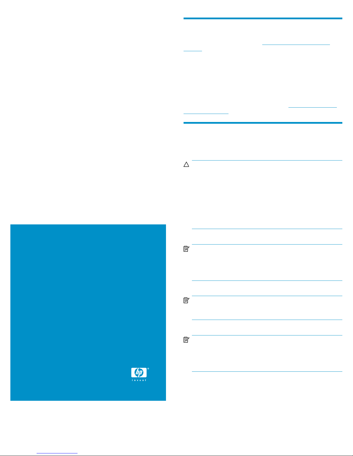
There are two fan modules on the rear of the disk enclosure. See Figure
1 for the locations.
2. Fan 21. Fan 1
Figure 1 Fan module locations
Verifying component failure
Before replacing the module, check the following and confirm with HP
support h
• Analyze any failure messages received. HP fault monitoring software
• Check the fan module status LED.
ttp://www.hp.com/support that it has failed:
provides a recommended action.
Table 1 Fan module status LED descriptions
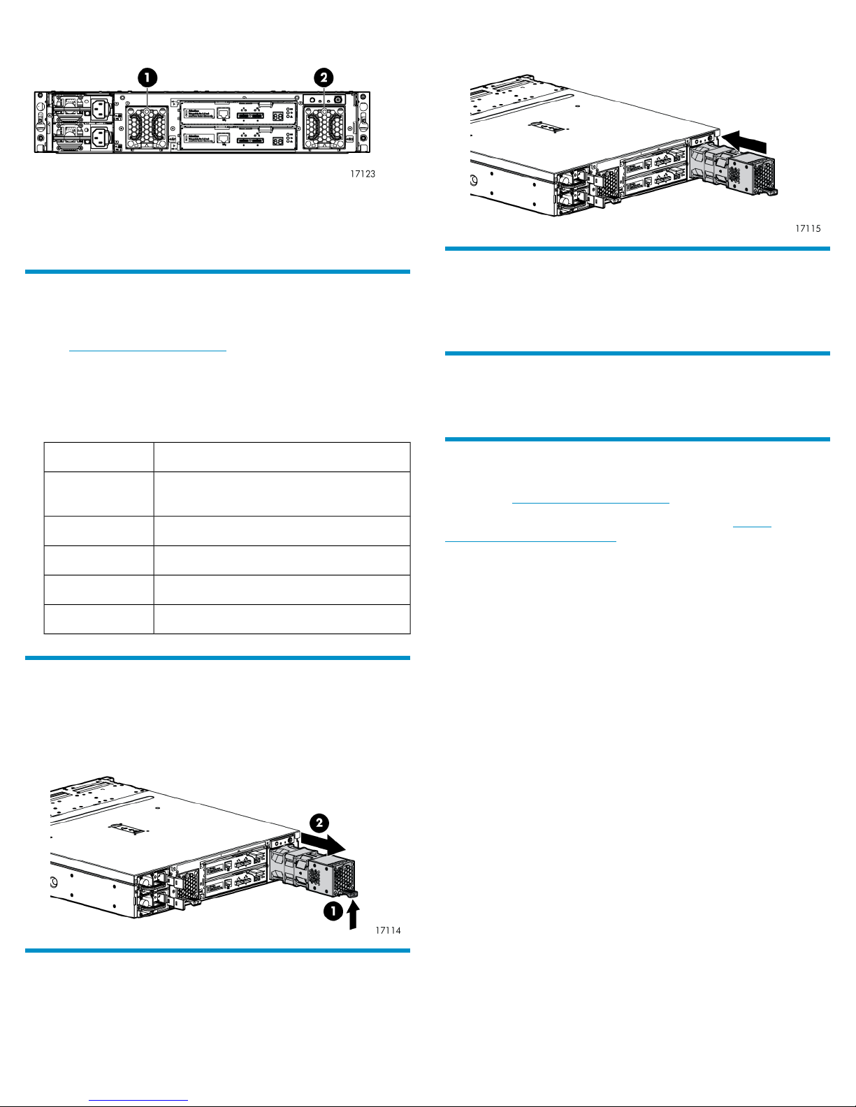
2. Push the fan module into the enclosure until a click is detected when
fully seated.
Verifying proper operation
Check the following to verify that the module is working properly:
• See Table 1 on page 2 and check for healthy LED patterns.
Returning the failed component
Follow instructions shipped with the replacement part.
DescriptionLED status
Off
No AC power to the module or the enclosure
is powered off
The module is being identifiedGreen—blinking
Healthy, no fault conditions detectedGreen—solid
Error, fault conditions detectedAmber—blinking
Error, problems detecting the module.Amber—solid
Removing a fan module
1. Lift up on the mounting latch (1).
2. Position one hand under the module, and with the other hand, pull
the module out of the enclosure (2).
Additional information
HP support: http://www.hp.com/support
HP resources (white papers and support documents): http://
www.hp.com/support/manuals
Installing a fan module
1. Insert the module into the enclosure opening.
Page 2
 Loading...