

Page 1
HP StorageWorks
P2000 G3 Modular Smart Array
Controller Module Replacement
Instructions
This document details procedures for replacing a failed
controller module in an HP StorageWorks P2000 G3
MSA system.
About this document
• Illustrations in this document show generic representations of modules
and enclosures; procedures are the same for all modules shipped
with this document.
• The Storage Management Utility (SMU) and the Command Line Inter-
face (CLI) can be used to manage the enclosure. Tasks in this document demonstrate using the SMU.
• For the latest product documentation, see the HP website at http://
www.hp.com/support/manuals. Under the storage banner, navigate
to the page for your storage enclosure.
Before you begin
Observe the following:
CAUTION:
• Removing a module from an operational enclosure significantly
changes air flow within the enclosure. Openings must be
populated for the enclosure to cool properly. Leave modules
in the enclosure until a replacement is available.
• Parts can be damaged by electrostatic discharge; use proper
anti-static protection. Keep parts in electrostatic containers
until needed and ensure you are properly grounded when
touching static-sensitive components.
© Copyright 2009, 2010 Hewlett-Packard Development Company,
L.P.
Second edition: March 2010
The information in this document is subject to change without notice.
Printed in the US.
www.hp.com
IMPORTANT:
When replacing both controllers in an operational enclosure,
do as follows:
1. Replace one controller as detailed in these instructions.
2. Wait 30 minutes. This pause ensures that the two controllers
and their ownership of the vdisks have enough time to fully
stabilize.
3. Examine system status and event logs to ensure that the system
is stable.
4. Replace the other controller as detailed in these instructions.
IMPORTANT:
When two controllers are installed in an enclosure, they must
be the same model. Mixing controller types in the same
enclosure is not supported.
NOTE:
To reduce impact on system performance, perform all
maintenance tasks during periods of low system activity or
during a system maintenance window.
*590365-002*
Page 1
Page 2
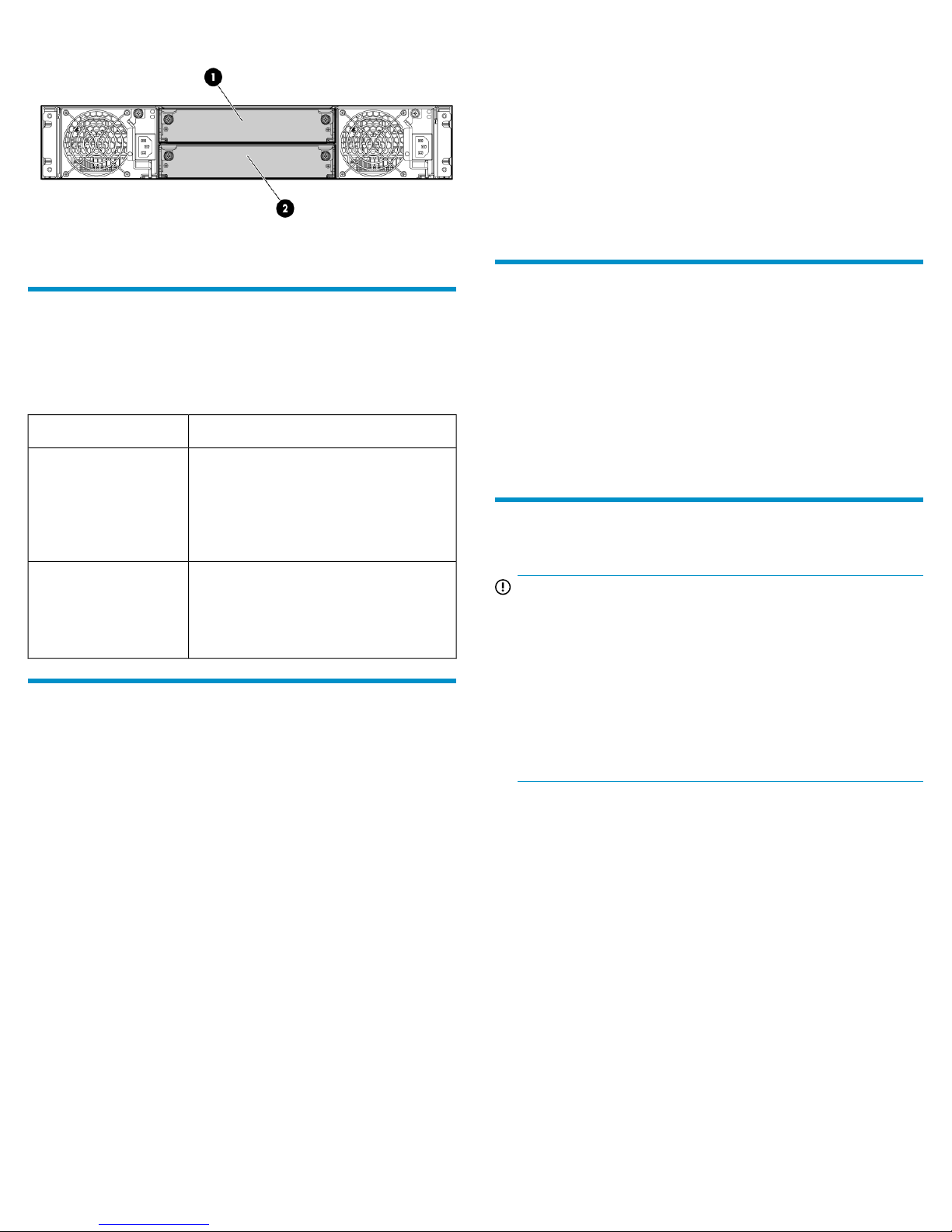
The following illustration shows controller module locations:
2. Controller B1. Controller A
Verifying module failure
Before replacing the module, look at the event log, software management
utilities, and device LEDs, to confirm that the module has failed.
Table 1 LED descriptions
DescriptionModule LED
• Solid Green = Module is operating
normally
OK LED
• Blink = System is starting up
• Off = Module is NOT operating nor-
mally
• For information about all hosts (IDs and names):
In the Configuration View panel, select Hosts and then click View >
Overview.
• For information about a specific host (IDs, names, and mappings):
In the Configuration View panel, expand the display under Hosts
and then select a specific host.
• For overview information, including host IDs and nicknames, in
the main section of the screen, select Host. Scroll down to see
details.
• For mapping information, in the main section of the screen, select
Maps. Scroll down to see details.
Enabling Partner Firmware Update
nl
(dual-controller configurations only)
In a dual-controller configuration, the Partner Firmware Update option
ensures that both controllers have the most recent version. HP
recommends enabling this feature.
To view or change the current Partner Firmware Update setting, select
the system in the Configuration View panel and then select Configuration
> Advanced Settings > Firmware. If needed, check the box and click
Apply.
Removing the failed module
• Solid Amber = Fault condition
Fault/Service Required
LED
• Blinking Amber = Hardware-controlled
power-up or cache flush/restore error
• Off = No fault conditions
Recording configuration settings
As a best practice, record system settings before replacing a controller
module.
To obtain key settings using the SMU, in the Configuration View panel,
select the system and then click the following menu options:
• For date, time, and NTP settings:
Configuration > System Settings > Date, Time
• For system information (name, contact, location, and description):
Configuration > System Settings > System Information
• For user information:
Configuration > Users > Modify User
• For email notification settings:
Configuration > Services > Email Notification
• For SNMP notification settings:
Configuration > Services > SNMP Notification
• For information about scheduled tasks:
View > Overview
In the main section of the page, select Schedules. Scroll down to see
details.
IMPORTANT:
• In a single-controller configuration, if transporting the Com-
pactFlash to a new controller, remove the controller only after
the cache is copied to CompactFlash, which is indicated by
the Cache Status LED being off.
• In a single-controller environment, I/O must be stopped and
the enclosure must be powered off prior to the replacement.
• In a dual-controller environment, if the failed controller is first
shut down, the controller may be hot-replaced in an operational enclosure.
1. In a dual-controller configuration, shut down the failed controller:
a. Select the system in the Configuration View panel and then
select Tools > Shut Down or Restart Controller.
b. Set the following options and then click OK:
• Operation=Shut down
• Controller Type=Storage
• Controller=A or B
The blue OK to Remove LED on the controller illuminates to
indicate that the controller can be safely removed.
2. Locate the enclosure in which the controller module OK to Remove
LED is blue.
3. In a single-controller environment, stop all I/O and remove power
from the enclosure.
4. Disconnect cables connected to the module. Label each cable to
facilitate reconnection.
Page 2
Page 3

5. Turn the thumbscrews until the screws disengage from the module
(1) and rotate both latches downward to disengage the module
from the internal connector (2).
6. Pull the module straight out of the enclosure (3).
NOTE:
For clarity, only relevant details are shown in this
illustration. Port and LED information is not included.
3. Carefully remove the CompactFlash from the new controller and set
it aside.
4. Insert the CompactFlash that you removed from the failed controller
and labeled “Data” into the new controller.
Transporting CompactFlash
nl
(single-controller configurations only)
CAUTION:
CompactFlash must be moved from the failed controller to the
new controller. If the CompactFlash is not moved to the new
controller, data loss or corruption is likely to occur.
1. If the controller has failed or does not start, make sure that
transporting the cache is the appropriate action to take as specified
in the user guide.
2. Carefully remove the CompactFlash from the controller, label it
“Data,” and set it aside.
Installing the new module
1. With the latches in the open position, slide the module into the
enclosure as far as it will go (1). If necessary, press lightly on the
top-center of the module to facilitate insertion.
2. Rotate the latches upward to engage the module with the internal
connector (2) and then, turn the thumbscrews finger-tight (3).
NOTE:
For clarity, only relevant details are shown in this
illustration. Port and LED information is not included.
Page 3
Page 4

3. Reconnect the cables.
NOTE:
After installing a controller in an operational,
dual-controller system, the new controller automatically
begins to initialize. If the firmware versions differ
between the two controllers, Partner Firmware Upgrade
feature brings the older firmware to the later firmware
level.
4. In operational systems, if additional hardware components, such
as a second controller, need replacing or installing, wait 30 minutes
before proceeding with those procedures. This time frame ensures
that the controller(s) and their ownership of vdisks are fully stabilized.
Verifying proper operation
Examine module status as indicated in Table 1.
If the Fault/Service Required LED is amber, the module has not gone
online and likely failed its self-test. Check the event log for errors and
then restart the controller to put the module online. To restart a controller,
do the following:
1. Select the system in the Configuration View panel and then select
Tools > Shut Down or Restart Controller.
2. Set the following options and then click OK:
• Operation=Restart
• Controller Type=Storage
• Controller=A or B
Additional information
HP P2000/MSA Disk Systems: http://www.hp.com/go/msa
HP storage: http://www.hp.com/storage
HP support: http://www.hp.com/support
HP documents: http://www.hp.com/support/manuals
Verifying configuration settings
After replacing a controller, verify that system configuration settings are
set properly for your environment. Repeat the commands shown in
“Recording configuration settings” on page 2 and compare the current
values with those recorded before the installation. If necessary, change
the settings to their previous values. For more information, see online
help or the enclosure user guide.
Verifying the firmware version
After installing a controller, verify that the latest firmware is installed on
all controllers in the enclosure. Go to the HP Support website at
nl
http://www.hp.com/support and navigate to the page for your
enclosure. If newer firmware is available, download the firmware from
the Web to your local system and install that latest version on the
controllers. For more information on firmware updates, see the enclosure
user guide.
Returning failed items
In materials shipped with the replacement, HP specifies whether the
failed component must be returned. Follow the provided instructions.
Page 4
 Loading...