

Page 1

hp StorageWorks
MSA SAN switch 2/8
Product Version: 1.0
First Edition (December 2002)
Part Number: 308999-001
installation
guide
The HP StorageWorks MSA SAN Switch 2/8 is a high-performance, 2 Gb/s, 8 port Fibre
Channel switch used to connect the Modular SAN Array 1000 storage device to hosts and
Enterprise Backup Solutions in a Storage Area Network.
Page 2

© Hewlett-Packard Company, 2002.
Hewlett-Packard Company makes no warranty of any kind with regard to this material, including, but not limited to,
the implied warranties of merchantability and fitness for a particular purpose. Hewlett-Packard shall not be liable for
errors contained herein or for incidental or consequential damages in connection with the furnishing, performance,
or use of this material.
This document contains proprietary information, which is protected by copyright. No part of this document may be
photocopied, reproduced, or translated into another language without the prior written consent of Hewlett-Packard.
The information contained in this document is subject to change without notice.
Compaq Computer Corporation is a wholly-owned subsidiary of Hewlett-Packard Company.
Microsoft, MS-DOS, Windows, Windows 2000, and Windows NT are registered trademarks of Microsoft
Corporation in the U.S. and/or other countries.
Java is a registered trademark of Sun Microsystems, Inc.
The Open Group, UNIX, are trademarks of The Open Group in the U.S. and/or other countries.
Hewlett-Packard Company shall not be liable for technical or editorial errors or omissions contained herein. The
information is provided “as is” without warranty of any kind and is subject to change without notice. The warranties
for Hewlett-Packard Company products are set forth in the express limited warranty statements accompanying such
products. Nothing herein should be construed as constituting an additional warranty.
MSA SAN Switch 2/8 Installation Guide
First Edition (December 2002)
Part Number: 308999-001
Page 3

contents
About this Guide. . . . . . . . . . . . . . . . . . . . . . . . . . . . . . . . . . . . . . . . . . . . . . . . . . . .7
Overview. . . . . . . . . . . . . . . . . . . . . . . . . . . . . . . . . . . . . . . . . . . . . . . . . . . . . . . . . . . . . . . . . . 8
Intended Audience . . . . . . . . . . . . . . . . . . . . . . . . . . . . . . . . . . . . . . . . . . . . . . . . . . . . . . . 8
Related Documentation . . . . . . . . . . . . . . . . . . . . . . . . . . . . . . . . . . . . . . . . . . . . . . . . . . . 8
Conventions . . . . . . . . . . . . . . . . . . . . . . . . . . . . . . . . . . . . . . . . . . . . . . . . . . . . . . . . . . . . . . . 9
Document Conventions . . . . . . . . . . . . . . . . . . . . . . . . . . . . . . . . . . . . . . . . . . . . . . . . . . . 9
Text Symbols . . . . . . . . . . . . . . . . . . . . . . . . . . . . . . . . . . . . . . . . . . . . . . . . . . . . . . . . . . . 9
Equipment Symbols . . . . . . . . . . . . . . . . . . . . . . . . . . . . . . . . . . . . . . . . . . . . . . . . . . . . . 10
Rack Stability . . . . . . . . . . . . . . . . . . . . . . . . . . . . . . . . . . . . . . . . . . . . . . . . . . . . . . . . . . . . . 11
Getting Help . . . . . . . . . . . . . . . . . . . . . . . . . . . . . . . . . . . . . . . . . . . . . . . . . . . . . . . . . . . . . . 12
HP Technical Support . . . . . . . . . . . . . . . . . . . . . . . . . . . . . . . . . . . . . . . . . . . . . . . . . . . 12
HP Storage Website . . . . . . . . . . . . . . . . . . . . . . . . . . . . . . . . . . . . . . . . . . . . . . . . . . . . . 12
HP Authorized Reseller . . . . . . . . . . . . . . . . . . . . . . . . . . . . . . . . . . . . . . . . . . . . . . . . . . 12
1 About the MSA SAN Switch 2/8 . . . . . . . . . . . . . . . . . . . . . . . . . . . . . . . . . . . . . . .13
MSA SAN Switch 2/8 Firmware Features . . . . . . . . . . . . . . . . . . . . . . . . . . . . . . . . . . . . . . . 15
MSA SAN Switch 2/8 Hardware Features. . . . . . . . . . . . . . . . . . . . . . . . . . . . . . . . . . . . . . . 16
MSA SAN Switch 2/8 Panel Description. . . . . . . . . . . . . . . . . . . . . . . . . . . . . . . . . . . . . . . . 17
LEDs . . . . . . . . . . . . . . . . . . . . . . . . . . . . . . . . . . . . . . . . . . . . . . . . . . . . . . . . . . . . . 18
Optical Ports . . . . . . . . . . . . . . . . . . . . . . . . . . . . . . . . . . . . . . . . . . . . . . . . . . . . . . . 18
Ethernet Port . . . . . . . . . . . . . . . . . . . . . . . . . . . . . . . . . . . . . . . . . . . . . . . . . . . . . . . 19
Serial Port . . . . . . . . . . . . . . . . . . . . . . . . . . . . . . . . . . . . . . . . . . . . . . . . . . . . . . . . . 19
Contents
2 Installing the MSA SAN Switch 2/8 . . . . . . . . . . . . . . . . . . . . . . . . . . . . . . . . . . . . .21
Verifying Carton Contents . . . . . . . . . . . . . . . . . . . . . . . . . . . . . . . . . . . . . . . . . . . . . . . . . . . 22
Installing the MSA SAN Switch 2/8 in the MSA1000. . . . . . . . . . . . . . . . . . . . . . . . . . . . . . 23
Installing an SFP Module . . . . . . . . . . . . . . . . . . . . . . . . . . . . . . . . . . . . . . . . . . . . . . . . . . . . 27
3 Configuring the MSA SAN Switch 2/8 . . . . . . . . . . . . . . . . . . . . . . . . . . . . . . . . . . .29
Requirements . . . . . . . . . . . . . . . . . . . . . . . . . . . . . . . . . . . . . . . . . . . . . . . . . . . . . . . . . . . . . 30
Entering Initial Configuration Settings through the CLI . . . . . . . . . . . . . . . . . . . . . . . . . . . . 31
3MSA SAN Switch 2/8 Installation Guide
Page 4

Contents
Accessing the CLI . . . . . . . . . . . . . . . . . . . . . . . . . . . . . . . . . . . . . . . . . . . . . . . . . . . . . . 31
Accessing the CLI through the Serial Port . . . . . . . . . . . . . . . . . . . . . . . . . . . . . . . . 31
Accessing the CLI through the Ethernet Port (via a Telnet Session) . . . . . . . . . . . . 33
Setting Network Addresses . . . . . . . . . . . . . . . . . . . . . . . . . . . . . . . . . . . . . . . . . . . . . . . 34
Connecting the MSA SAN Switch 2/8 to the Ethernet Network . . . . . . . . . . . . . . . . . . . . . . 35
Completing MSA SAN Switch 2/8 Configuration. . . . . . . . . . . . . . . . . . . . . . . . . . . . . . . . . 36
Verifying Operation . . . . . . . . . . . . . . . . . . . . . . . . . . . . . . . . . . . . . . . . . . . . . . . . . . . . . . . . 36
4 Managing the MSA SAN Switch 2/8 . . . . . . . . . . . . . . . . . . . . . . . . . . . . . . . . . . . .37
Command Line Interface (CLI) Overview . . . . . . . . . . . . . . . . . . . . . . . . . . . . . . . . . . . . . . . 39
Web Tools Overview . . . . . . . . . . . . . . . . . . . . . . . . . . . . . . . . . . . . . . . . . . . . . . . . . . . . . . . 40
Optional Management Tools . . . . . . . . . . . . . . . . . . . . . . . . . . . . . . . . . . . . . . . . . . . . . . . . . 42
ISL Trunking . . . . . . . . . . . . . . . . . . . . . . . . . . . . . . . . . . . . . . . . . . . . . . . . . . . . . . . . . . 42
QuickLoop . . . . . . . . . . . . . . . . . . . . . . . . . . . . . . . . . . . . . . . . . . . . . . . . . . . . . . . . . . . . 43
Fabric Watch . . . . . . . . . . . . . . . . . . . . . . . . . . . . . . . . . . . . . . . . . . . . . . . . . . . . . . . . . . 43
Advanced Performance Monitoring. . . . . . . . . . . . . . . . . . . . . . . . . . . . . . . . . . . . . . . . . 43
Extended Fabrics . . . . . . . . . . . . . . . . . . . . . . . . . . . . . . . . . . . . . . . . . . . . . . . . . . . . . . . 44
Displaying the Optional Feature Licenses . . . . . . . . . . . . . . . . . . . . . . . . . . . . . . . . . . . . 44
Enabling Licensed Features . . . . . . . . . . . . . . . . . . . . . . . . . . . . . . . . . . . . . . . . . . . . . . . 44
LED Activity Definitions . . . . . . . . . . . . . . . . . . . . . . . . . . . . . . . . . . . . . . . . . . . . . . . . . . . . 45
Switch Readiness LED Definitions . . . . . . . . . . . . . . . . . . . . . . . . . . . . . . . . . . . . . . . . . 46
Port Speed LED Definitions. . . . . . . . . . . . . . . . . . . . . . . . . . . . . . . . . . . . . . . . . . . . . . . 46
Port Status LED Definitions. . . . . . . . . . . . . . . . . . . . . . . . . . . . . . . . . . . . . . . . . . . . . . . 47
MSA SAN Switch 2/8 POST and Diagnostic Tests . . . . . . . . . . . . . . . . . . . . . . . . . . . . . . . . 48
POST Results . . . . . . . . . . . . . . . . . . . . . . . . . . . . . . . . . . . . . . . . . . . . . . . . . . . . . . . . . . 48
Disabling POST . . . . . . . . . . . . . . . . . . . . . . . . . . . . . . . . . . . . . . . . . . . . . . . . . . . . . . . . 48
Diagnostic Tests. . . . . . . . . . . . . . . . . . . . . . . . . . . . . . . . . . . . . . . . . . . . . . . . . . . . . . . . 49
5 Backing Up Configuration Data and Upgrading Firmware . . . . . . . . . . . . . . . . . . . .51
Backing Up System Configuration Settings. . . . . . . . . . . . . . . . . . . . . . . . . . . . . . . . . . . . . . 52
Restoring System Configuration Settings. . . . . . . . . . . . . . . . . . . . . . . . . . . . . . . . . . . . . . . . 53
Upgrading or Restoring the Switch Firmware . . . . . . . . . . . . . . . . . . . . . . . . . . . . . . . . . . . . 54
Downloading New Switch Firmware through the CLI . . . . . . . . . . . . . . . . . . . . . . . . . . 54
Determining Your Firmware Version through the CLI. . . . . . . . . . . . . . . . . . . . . . . 54
Performing a Firmware Upgrade through the CLI . . . . . . . . . . . . . . . . . . . . . . . . . . 55
Downloading New Switch Firmware through Web Tools. . . . . . . . . . . . . . . . . . . . . . . . 56
Determining Your Firmware Version through Web Tools . . . . . . . . . . . . . . . . . . . . 56
Performing a Firmware Upgrade through Web Tools. . . . . . . . . . . . . . . . . . . . . . . . 57
4 MSA SAN Switch 2/8 Installation Guide
Page 5

Contents
A Regulatory Compliance Notices . . . . . . . . . . . . . . . . . . . . . . . . . . . . . . . . . . . . . . . .59
Regulatory Compliance Identification Numbers . . . . . . . . . . . . . . . . . . . . . . . . . . . . . . . . . . 59
Federal Communications Commission Notice . . . . . . . . . . . . . . . . . . . . . . . . . . . . . . . . . . . . 59
Class A Equipment. . . . . . . . . . . . . . . . . . . . . . . . . . . . . . . . . . . . . . . . . . . . . . . . . . . . . . 60
Declaration of Conformity for Products Marked with the FCC Logo . . . . . . . . . . . . . . . 60
Modifications . . . . . . . . . . . . . . . . . . . . . . . . . . . . . . . . . . . . . . . . . . . . . . . . . . . . . . . . . . 60
Network and Serial Cables. . . . . . . . . . . . . . . . . . . . . . . . . . . . . . . . . . . . . . . . . . . . . . . . 60
Canadian Notice (Avis Canadien) . . . . . . . . . . . . . . . . . . . . . . . . . . . . . . . . . . . . . . . . . . 60
Class A Equipment . . . . . . . . . . . . . . . . . . . . . . . . . . . . . . . . . . . . . . . . . . . . . . . . . . 60
European Union Notice . . . . . . . . . . . . . . . . . . . . . . . . . . . . . . . . . . . . . . . . . . . . . . . . . . . . . 61
China Taiwan Notice . . . . . . . . . . . . . . . . . . . . . . . . . . . . . . . . . . . . . . . . . . . . . . . . . . . . . . . 61
Japanese Notice . . . . . . . . . . . . . . . . . . . . . . . . . . . . . . . . . . . . . . . . . . . . . . . . . . . . . . . . . . . 62
Laser Devices . . . . . . . . . . . . . . . . . . . . . . . . . . . . . . . . . . . . . . . . . . . . . . . . . . . . . . . . . . . . . 63
Laser Safety Warnings. . . . . . . . . . . . . . . . . . . . . . . . . . . . . . . . . . . . . . . . . . . . . . . . . . . 63
Compliance with CDRH Regulations . . . . . . . . . . . . . . . . . . . . . . . . . . . . . . . . . . . . 63
Compliance with International Regulations . . . . . . . . . . . . . . . . . . . . . . . . . . . . . . . 63
Laser Product Label. . . . . . . . . . . . . . . . . . . . . . . . . . . . . . . . . . . . . . . . . . . . . . . . . . 64
Laser Information . . . . . . . . . . . . . . . . . . . . . . . . . . . . . . . . . . . . . . . . . . . . . . . . . . . 64
B Electrostatic Discharge. . . . . . . . . . . . . . . . . . . . . . . . . . . . . . . . . . . . . . . . . . . . . . .65
Grounding Methods . . . . . . . . . . . . . . . . . . . . . . . . . . . . . . . . . . . . . . . . . . . . . . . . . . . . . . . . 66
C I/O Connection Specifications . . . . . . . . . . . . . . . . . . . . . . . . . . . . . . . . . . . . . . . . .67
Ethernet Port Specifications . . . . . . . . . . . . . . . . . . . . . . . . . . . . . . . . . . . . . . . . . . . . . . . . . . 68
Index . . . . . . . . . . . . . . . . . . . . . . . . . . . . . . . . . . . . . . . . . . . . . . . . . . . . . . . . . . .69
5MSA SAN Switch 2/8 Installation Guide
Page 6

Contents
Figures
1 An MSA SAN Switch 2/8 installed in the primary slot. . . . . . . . . . . . . . . . . . . . . . . . . . 13
2 MSA SAN Switch 2/8 . . . . . . . . . . . . . . . . . . . . . . . . . . . . . . . . . . . . . . . . . . . . . . . . . . . 17
3 Carton contents. . . . . . . . . . . . . . . . . . . . . . . . . . . . . . . . . . . . . . . . . . . . . . . . . . . . . . . . . 22
4 Removing the Fibre Channel I/O Module . . . . . . . . . . . . . . . . . . . . . . . . . . . . . . . . . . . . 24
5 Inserting the MSA SAN Switch 2/8 into the vacant slot . . . . . . . . . . . . . . . . . . . . . . . . . 25
6 Removing the blanking panel. . . . . . . . . . . . . . . . . . . . . . . . . . . . . . . . . . . . . . . . . . . . . . 26
7 Installing an SFP . . . . . . . . . . . . . . . . . . . . . . . . . . . . . . . . . . . . . . . . . . . . . . . . . . . . . . . 27
8 CLI initial menu . . . . . . . . . . . . . . . . . . . . . . . . . . . . . . . . . . . . . . . . . . . . . . . . . . . . . . . . 39
9 Initial Web Tools display. . . . . . . . . . . . . . . . . . . . . . . . . . . . . . . . . . . . . . . . . . . . . . . . . 41
10 LED locations on the MSA SAN Switch 2/8. . . . . . . . . . . . . . . . . . . . . . . . . . . . . . . . . . 45
11 Web Tools initial Fabric View menu. . . . . . . . . . . . . . . . . . . . . . . . . . . . . . . . . . . . . . . . 56
12 Firmware Upgrade tab . . . . . . . . . . . . . . . . . . . . . . . . . . . . . . . . . . . . . . . . . . . . . . . . . . . 58
Tables
1 Document Conventions . . . . . . . . . . . . . . . . . . . . . . . . . . . . . . . . . . . . . . . . . . . . . . . . . . . 9
2 System Assigned Switch Names . . . . . . . . . . . . . . . . . . . . . . . . . . . . . . . . . . . . . . . . . . . 14
3 Serial Port Settings. . . . . . . . . . . . . . . . . . . . . . . . . . . . . . . . . . . . . . . . . . . . . . . . . . . . . . 32
4 Switch Readiness LED Definitions . . . . . . . . . . . . . . . . . . . . . . . . . . . . . . . . . . . . . . . . . 46
5 Port Speed LED Definitions. . . . . . . . . . . . . . . . . . . . . . . . . . . . . . . . . . . . . . . . . . . . . . . 46
6 Port Status LEDs . . . . . . . . . . . . . . . . . . . . . . . . . . . . . . . . . . . . . . . . . . . . . . . . . . . . . . . 47
7 Laser Specifications . . . . . . . . . . . . . . . . . . . . . . . . . . . . . . . . . . . . . . . . . . . . . . . . . . . . . 64
8 Serial Port Cabling Pin Layout . . . . . . . . . . . . . . . . . . . . . . . . . . . . . . . . . . . . . . . . . . . . 67
9 Ethernet Port Cabling Pin Layout . . . . . . . . . . . . . . . . . . . . . . . . . . . . . . . . . . . . . . . . . . 68
6 MSA SAN Switch 2/8 Installation Guide
Page 7

about this
guide
This installation guide provides information to help you install, configure, and
manage the HP StorageWorks MSA SAN Switch 2/8.
About this Guide topics include:
■ Overview, page 8
■ Conventions, page 9
■ Rack Stability, page 11
■ Getting Help, page 12
About this Guide
About this Guide
7MSA SAN Switch 2/8 Installation Guide
Page 8

About this Guide
Overview
This section discusses the following topics:
■ Intended Audience
■ Related Documentation
Intended Audience
This book is intended for use by customers and authorized service providers who
are experienced with the following:
■ Configuration aspects of customer Storage Area Networks (SAN)
■ Customer host environments, such as Microsoft Windows
Novell NetWare
Related Documentation
In addition to this guide, HP provides several additional supporting documents for
this switch.
TM
, OpenVMSTM, or Tru64 UNIX
TM.
TM
, LinuxTM,
The following documents are available on both the HP StorageWorks SAN
Switch Documentation CD, included in the shipping carton with the switch, and
the HP website.
■ HP StorageWorks Fabric OS Procedures User Guide
■ HP StorageWorks Fabric OS Reference Guide
■ HP StorageWorks Web Tools User Guide
■ HP StorageWorks ISL Trunking User Guide
■ HP StorageWorks Zoning User Guide
■ HP StorageWorks MIB Reference Guide
■ HP StorageWorks QuickLoop User Guide
■ HP StorageWorks Advanced Performance Monitoring User Guide
■ HP StorageWorks Extended Fabric User Guide
■ HP StorageWorks Fabric Watch User Guide
For information about SANs, refer to the HP StorageWorks SAN Design
Reference Guide, available at the HP website.
8 MSA SAN Switch 2/8 Installation Guide
Page 9
Conventions
Conventions consist of the following:
■ Document Conventions
■ Text Symbols
■ Equipment Symbols
Document Conventions
The document conventions included in Tab le 1 apply in most cases.
Table 1: Document Conventions
Cross-reference links Figure 1
About this Guide
Element Convention
Text Symbols
Key and field names, menu items,
buttons, and dialog box titles
File names, application names, and text
emphasis
User input, command and directory
names, and system responses (output
and messages)
Variables <monospace, italic font>
Website addresses Underlined sans serif font text:
Bold
Italics
Monospace font
COMMAND NAMES are uppercase
monospace font unless they are case
sensitive
http://www.hp.com
The following symbols may be found in the text of this guide. They have the
following meanings.
WARNING: Text set off in this manner indicates that failure to follow
directions in the warning could result in bodily harm or death.
MSA SAN Switch 2/8 Installation Guide
9
Page 10
About this Guide
Caution: Text set off in this manner indicates that failure to follow directions
could result in damage to equipment or data.
Note: Text set off in this manner presents commentary, sidelights, or interesting points
of information.
Equipment Symbols
The following equipment symbols may be found on hardware for which this guide
pertains. They have the following meanings.
Any enclosed surface or area of the equipment marked with these
symbols indicates the presence of electrical shock hazards. Enclosed
area contains no operator serviceable parts.
WARNING: To reduce the risk of personal injury from electrical shock
hazards, do not open this enclosure.
Any RJ-45 receptacle marked with these symbols indicates a network
interface connection.
WARNING: To reduce the risk of electrical shock, fire, or damage to the
equipment, do not plug telephone or telecommunications connectors
into this receptacle.
Any surface or area of the equipment marked with these symbols
indicates the presence of a hot surface or hot component. Contact with
this surface could result in injury.
WARNING: To reduce the risk of personal injury from a hot component,
allow the surface to cool before touching.
10 MSA SAN Switch 2/8 Installation Guide
Page 11
About this Guide
Power supplies or systems marked with these symbols indicate the
presence of multiple sources of power.
WARNING: To reduce the risk of personal injury from electrical
shock, remove all power cords to completely disconnect power
from the power supplies and systems.
Any product or assembly marked with these symbols indicates that the
component exceeds the recommended weight for one individual to
handle safely.
WARNING: To reduce the risk of personal injury or damage to the
equipment, observe local occupational health and safety requirements
and guidelines for manually handling material.
Rack Stability
Rack stability protects personal and equipment.
WARNING: To reduce the risk of personal injury or damage to the
equipment, be sure that:
■ The leveling jacks are extended to the floor.
■ The full weight of the rack rests on the leveling jacks.
■ In single rack installations, the stabilizing feet are attached to the rack.
■ In multiple rack installations, the racks are coupled.
■ Only one rack component is extended at any time. A rack may become
unstable if more than one rack component is extended for any reason.
MSA SAN Switch 2/8 Installation Guide
11
Page 12

About this Guide
Getting Help
If you have a question after reading this guide, contact an HP authorized service
provider or access our website at
HP Technical Support
In North America, call technical support at 1-800-652-6672, available 24 hours a
day, 7 days a week.
Note: For continuous quality improvement, calls may be recorded or monitored.
Outside North America, call technical support at the nearest location. Telephone
numbers for worldwide technical support are listed on the HP website under
support at
Be sure to have the following information available before calling:
http://www.h p.com
http://www.h p.com
.
.
■ Technical support registration number (if applicable)
■ Product model names, numbers, and serial numbers
■ Exact text of any applicable error messages
■ Operating system type and revision level
■ Detailed, specific questions
HP Storage Website
The HP website has the latest information on this product, as well as the latest
drivers. Access storage at
appropriate product or solution.
HP Authorized Reseller
For the name of your nearest HP authorized reseller:
■ In the United States, call 1-800-345-1518
■ In Canada, call 1-800-263-5868
■ Elsewhere, see the HP website for locations and telephone numbers at
http://www.hp .com
http://www.hp.c o m
.
. From this website, select the
12 MSA SAN Switch 2/8 Installation Guide
Page 13
About the MSA SAN
Switch 2/8
The HP StorageWorks MSA SAN Switch 2/8 is a high-performance, 2 Gb/s,
8 port Fibre Channel switch, designed specifically for installation in the Modular
SAN Array 1000 (MSA1000) storage device, to connect the MSA1000 to hosts
and Enterprise Backup Solutions in a Storage Area Network (SAN).
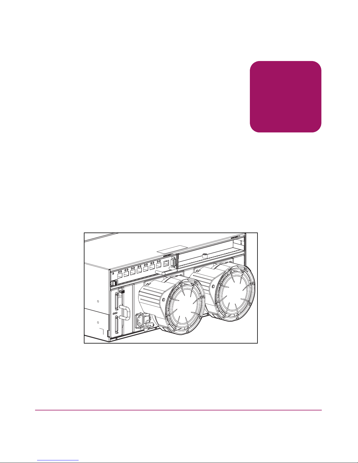
The MSA1000 provides two slots for embedded interconnect devices. The
MSA1000 ships standard with one Fibre Channel I/O Module in the primary slot
and a blanking panel in the secondary slot. Available embedded interconnect
options include the provided Fibre Channel I/O Module, an MSA HUB 2/3, and
this MSA SAN Switch. If a redundant configuration is needed, two MSA SAN
Switches may be installed in the MSA1000.
1
Figure 1: An MSA SAN Switch 2/8 installed in the primary slot
13MSA SAN Switch 2/8 Installation Guide
Page 14
About the MSA SAN Switch 2/8
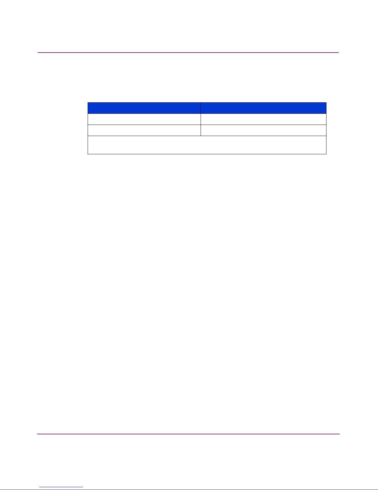
Each switch is assigned a system-generated name, dependant on the slot in which
it is installed.
Table 2: System Assigned Switch Names
MSA1000 Sot Location Switch Name
Primary (rear-left)
Secondary (rear-right)
MSA1000 Controller Name
MSA1000 Controller Name
-switch1
-switch2
Note: The first portion of the switch name is the name assigned to the MSA1000
Controller installed in the associated controller slot.
This chapter provides the following information:
■ MSA SAN Switch 2/8 Firmware Features
■ MSA SAN Switch 2/8 Hardware Features
■ MSA SAN Switch 2/8 Panel Description
14 MSA SAN Switch 2/8 Installation Guide
Page 15

MSA SAN Switch 2/8 Firmware Features
■ Universal and self-configuring optical ports for the following protocols:
— E_Port (expansion port)
— F_Port (fabric port that is not loop capable)
— FL_Port (fabric port that is loop capable)
■ Automatic re-routing through the Fabric Shortest Path First (FSPF) algorithm
■ Application Programming Interface (API) that allows applications to interface
with switch services
■ Per port statistics for diagnosing and isolating problem ports without
disrupting switch operations
■ Per port error detection and fault isolation that automatically disables failing
ports and restarts when the problem is resolved
■ Industry standard Simple Network Management Protocol (SNMP)
Management Information Base (MIB) support
About the MSA SAN Switch 2/8
■ Automatic self-discovery that discovers and registers host server and storage
devices
■ Zoning functionality that provides a means to allocate storage controllers to
groups of computers
Zoning allows you to create logical subsets of the fabric to accommodate
closed user groups or to create functional user groups within a fabric.
For more information, refer to the HP StorageWorks Zoning User Guide. This
guide is included on the HP StorageWorks SAN Switch Documentation CD.
■ Web Tools graphical user interface, for managing the switch from a browser
such as Internet Explorer
For more information, refer to the HP StorageWorks Web Tools User Guide.
This guide is included on the Documentation CD.
■ Fabric Operating System provides a command line interface (CLI), for
managing the switch through either a workstation connected to the serial port
or through a telnet session on the Ethernet port
For more information, refer to the HP StorageWorks Fabric Operating System
Procedures User Guide. This guide is included on the Documentation CD.
15MSA SAN Switch 2/8 Installation Guide
Page 16

About the MSA SAN Switch 2/8
MSA SAN Switch 2/8 Hardware Features
MSA SAN Switch hardware support includes:
■ Embedded design specifically for the MSA1000
■ Hot-pluggability
The switch can be installed or replaced without power cycling the MSA1000.
When adding or replacing a switch, allow sufficient time to complete the
POST tests and the configuration tasks before using.
■ Redundancy
In redundant fabric configurations, you can install two MSA SAN Switches to
support the redundant MSA1000 controllers.
■ Single chip ASIC switch design
■ Eight ports
— Seven available 2-Gb/s Fibre Channel ports are compatible with Small
Form Factor Pluggable (SFPs) transceiver interconnects (Port 1 through
Port 7)
— One internal port (Port 0) for interfacing with the MSA1000 Array
Controller, using F_Port protocol
■ Per port automatic negotiation to the highest possible speed
■ One IEEE compliant 10/100 Mb/s Ethernet management port; able to
auto-sense a straight-through cable or crossover cable configuration
■ One DB-9 serial port
■ A total of 15 LEDs:
— One Switch Readiness LED
— One port status LED for each of the seven available ports
— One port speed LED for each of the seven available ports
16 MSA SAN Switch 2/8 Installation Guide
Page 17
MSA SAN Switch 2/8 Panel Description
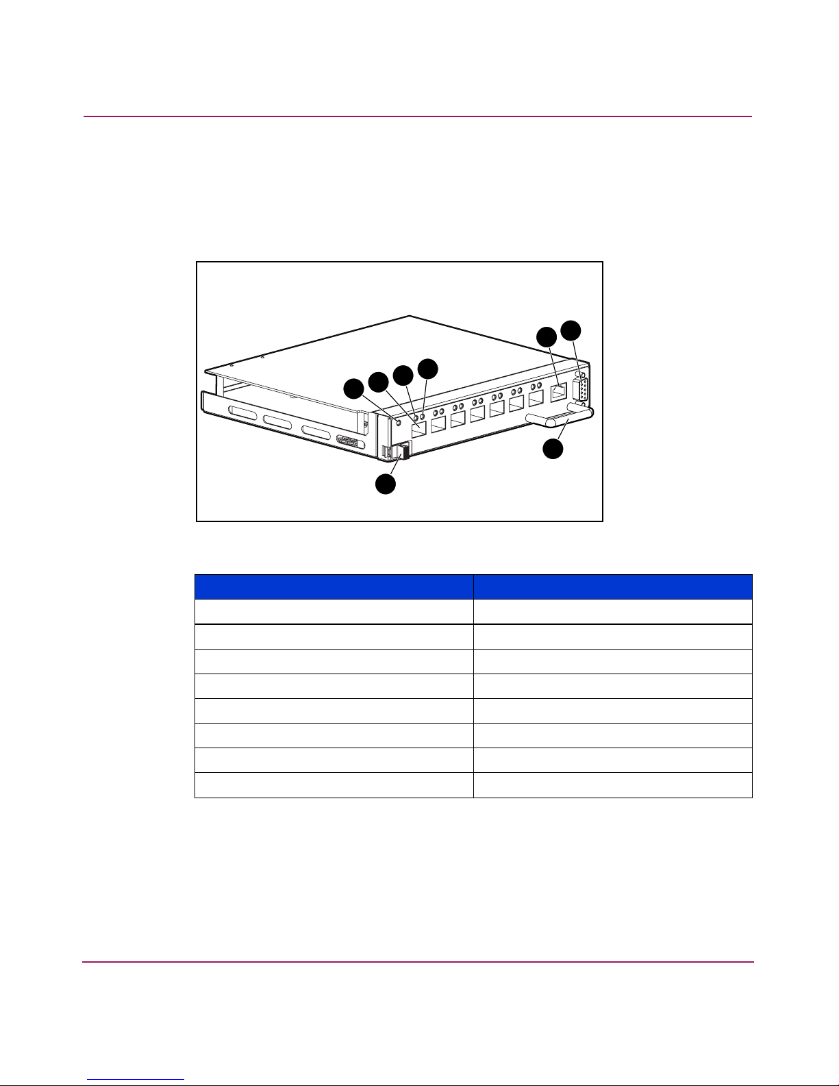
Figure 2 is an illustration of the MSA SAN Switch. The switch panel houses the
seven available fiber optic ports, the Ethernet port, the serial port, and the
corresponding LEDs.
5
4
3
2
1
About the MSA SAN Switch 2/8
7
6
8
Figure 2: MSA SAN Switch 2/8
Item Description
1 Latch
2 Switch readiness LED
3 Optical ports (7)
4 Port status LED
5 Port speed LED
6 10/100 Ethernet port, RJ-45
7 Serial port, DB-9
8 Handle
17MSA SAN Switch 2/8 Installation Guide
Page 18

About the MSA SAN Switch 2/8
LEDs
The LEDs on the switch provide activity or status information.
For detailed information on all of the switch LEDs, see “Configuring the MSA
SAN Switch 2/8.”
Optical Ports
All optical ports support full fabric capability, allowing the MSA SAN Switch to
link or cascade to other HP StorageWorks Fibre Channel switches, building a
highly scalable SAN fabric.
The optical ports are connected via Small Form Factor Pluggable (SFP) media,
which are universal and self-configuring.
Each optical port supports link speeds up to 2 Gb/s and, independent of the other
ports, automatically negotiates to the highest speed possible for the devices
connected to that port.
These ports conform to the American National Standards Institute (ANSI) Fibre
Channel, FC-PI specification for Fibre Channel SFP transceivers.
The optical ports are numbered from left to right and are color-coded into two
groups, indicating which ports can be used in the same ISL Trunking group.
ISL trunking is an optional feature that enables distribution of traffic over the
combined bandwidth of up to four ISLs between two directly connected switches,
while preserving in-order delivery. Ports 1 through 3 can be used in a three-port
trunking group and ports 4 through 7 can be used in a four-port trunking group,
creating aggregate bandwidths of 6 Gb/s and 8 Gb/s, respectively. For specific
information about ISL trunking, refer to the HP StorageWorks ISL Trunking User
Guide. This guide is included on the documentation CD, included in the shipping
carton.
18 MSA SAN Switch 2/8 Installation Guide
Page 19

Ethernet Port
Serial Port
About the MSA SAN Switch 2/8
This connector is used to connect the switch to the SAN management network.
Switch configuration and management tasks can be made through the Ethernet
port either by using a telnet connection to access the CLI or by using a standard
web browser to access the Web Tools graphical user interface.
By default, the switch is configured to use an IP address of 10.77.77.77.
See “Configuring the MSA SAN Switch 2/8” for information on setting the IP
address.
This connector is provided for switch configuration and management. You can
access the CLI through a terminal or terminal emulator connected to this port.
The MSA SAN Switch is designed to function directly out of its shipping carton,
only requiring the IP address to be set.
See “Configuring the MSA SAN Switch 2/8” for more information.
19MSA SAN Switch 2/8 Installation Guide
Page 20

About the MSA SAN Switch 2/8
20 MSA SAN Switch 2/8 Installation Guide
Page 21

Installing the MSA SAN
Switch 2/8
This chapter discusses the following topics:
■ Verifying Carton Contents, page 22
■ Installing the MSA SAN Switch 2/8 in the MSA1000, page 23
■ Installing an SFP Module, page 27
2
21MSA SAN Switch 2/8 Installation Guide
Page 22
Installing the MSA SAN Switch 2/8
Verifying Carton Contents
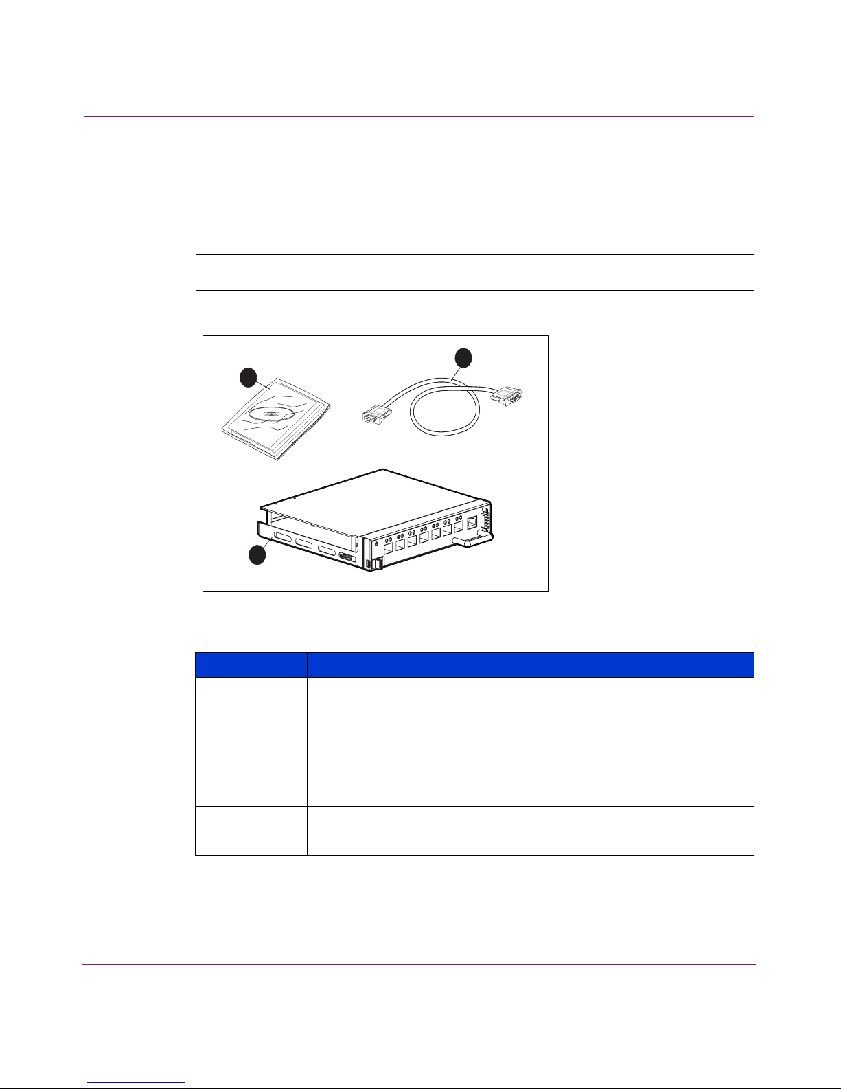
Unpack and inspect the MSA SAN Switch carton contents. Verify that the carton
contains the items shown in Figure 3 and listed in the supporting table.
Note: If any items are damaged or missing, contact HP or an HP Authorized reseller.
1
3
2
Figure 3: Carton contents
Item Description
1 MSA SAN Switch 2/8 product accessory bag containing:
■ Printed
HP StorageWorks MSA SAN Switch 2/8 Installation
Guide
■ Documentation CD
■ License agreement
■ Warranty Information
2 HP StorageWorks MSA SAN Switch 2/8
3 RS-232 serial cable (straight through)
22 MSA SAN Switch 2/8 Installation Guide
Page 23

Installing the MSA SAN Switch 2/8
Installing the MSA SAN Switch 2/8 in the MSA1000
Caution: To prevent static shock, which can damage electrical equipment, use
industry accepted handling practices when unpacking and moving the switch.
See the “Electrostatic Discharge” appendix for more information.
Note: The MSA SAN Switch is a hot-pluggable component of the MSA1000 and can
be installed and uninstalled regardless of whether the MSA1000 is powered on.
Caution: Depending on the operating systems of the servers already attached
to the MSA1000 and the applications they are running, verify that they can
tolerate a temporary disruption while the MSA SAN Switch is installed.
Contact your operating system and application vendors for verification.
23MSA SAN Switch 2/8 Installation Guide
Page 24

Installing the MSA SAN Switch 2/8
1. If the MSA SAN Switch is replacing the provided Modular SAN Array Fibre
Channel I/O Module in the primary slot of the MSA1000, remove the I/O
Module from the bay.
To remove the I/O module, slide and hold the latch on the I/O Module to the
right and then grasp the handle and pull the I/O Module straight out of the bay.
See Figure 4 for an illustration.
Figure 4: Removing the Fibre Channel I/O Module
Note: Carefully remove and save the SFP from the Fibre Channel I/O Module; it can
be re-used in the MSA SAN Switch. See “Installing an SFP Module” for information on
handling SFPs.
2. Remove the MSA SAN Switch from its protective bag.
24 MSA SAN Switch 2/8 Installation Guide
Page 25

Installing the MSA SAN Switch 2/8
3. Insert the MSA SAN Switch into the vacated slot of the MSA1000.
To insert the switch, orient the switch with the handle on the right and insert
the edge that contains the rear backplane interface connector into the bay until
the connector seats and the latch clicks.
See Figure 5 for an illustration.
Figure 5: Inserting the MSA SAN Switch 2/8 into the vacant slot
If the MSA1000 is powered on, the MSA SAN Switch is powered on as soon
as it is installed.
The switch begins running a Power-on Self-test (POST), a system diagnostic
that requires approximately seven minutes to complete. See “Interpreting
POST Results” under “Managing the MSA SAN Switch 2/8,” for more
information about POST.
25MSA SAN Switch 2/8 Installation Guide
Page 26

Installing the MSA SAN Switch 2/8
4. For redundant-controller configurations only:
If an MSA SAN Switch is being installed in the secondary slot, remove the
blanking panel and install the switch in the open slot, as previously illustrated
in step 2 and step 3.
To remove the blanking panel, loosen the thumbscrew that holds the blanking
panel in place and remove the blank from the back of the unit.
See Figure 6 for an illustration of removing the blanking panel.
1
2
Figure 6: Removing the blanking panel
Save the blanking panel for re-use in the event the redundant switch is ever
removed. Either an embedded device or the blanking panel must always be in
place for proper airflow and cooling.
Note: Do not connect the switch to the network until the IP address is correctly set. The
shipping IP address for the MSA SAN Switch is 10.77.77.77. For instructions on setting
the IP address, see “Configuring the MSA SAN Switch 2/8.”
26 MSA SAN Switch 2/8 Installation Guide
Page 27

Installing an SFP Module
Use these steps to connect the SFPs in the ports of the MSA SAN Switch, as
required.
1. Remove the shipping plugs from the appropriate ports on the switch panel.
2. Position the SFP so the key (the tab near the cable-end of the SFP) is on top.
3. Insert the SFP into the port until it is firmly seated and the latching
mechanism clicks.
Note: The SFP is keyed so that it can only be inserted with the correct orientation into
the port. If the SFP does not slide in easily, check the orientation.
See Figure 7 for an illustration of the fiber cable, the SFP module and tab, and
the optical port.
Installing the MSA SAN Switch 2/8
3
2
1
Figure 7: Installing an SFP
Note: To remove an SFP from an optical port, carefully grasp the tab at the top of the
SFP and pull the module
Do not pull up on the tab; you may damage your SFP module.
straight out of the port
.
27MSA SAN Switch 2/8 Installation Guide
Page 28

Installing the MSA SAN Switch 2/8
Note: For dust and ESD (electrostatic discharge) protection, a cover is provided for
each optical port and should be kept on the port whenever the port is not in use.
Caution: Do not connect the switch to a configured SAN without first
configuring the switch.
4. Connect the cables to the SFPs as appropriate to the fabric topology, by
positioning each cable so that the key (the ridge on one side of the cable
connector) is aligned with the slot in the SFP.
Insert the cable into the SFP until it is firmly seated and the latching
mechanism clicks.
5. Proceed to the following chapter in this guide to configure the MSA SAN
Switch for your SAN and verify its operation.
28 MSA SAN Switch 2/8 Installation Guide
Page 29

Configuring the MSA SAN
Switch 2/8
The process of configuring the MSA SAN Switch includes the initial process of
changing the factory-set IP address to a valid IP address for your environment.
The IP address must initially be entered using the CLI.
After the IP address is set, additional parameters must be entered, but they may be
entered through either the CLI or the Web Tools.
This chapter discusses:
■ Requirements, page 30
■ Entering Initial Configuration Settings through the CLI, page 31
■ Connecting the MSA SAN Switch 2/8 to the Ethernet Network, page 35
■ Completing MSA SAN Switch 2/8 Configuration, page 36
■ Verifying Operation, page 36
3
29MSA SAN Switch 2/8 Installation Guide
Page 30

Configuring the MSA SAN Switch 2/8
Requirements
The following items are required to set network addressing:
■ An IP address from your Network Administrator
■ An installed MSA SAN Switch
■ Serial cable (supplied with the switch) for connecting the switch to the
workstation
This cable must be a straight-through cable.
■ A local workstation (desktop or notebook computer) with a serial terminal
connection
■ RS-232 serial communication software (for example, ProComm Plus or
HyperTerminal)
■ Ethernet cable for connecting the switch to the workstation or to a network
containing the workstation
This cable can be a cross-over cable or a straight-through cable.
■ SFPs and fiber cables, as required, to connect the switch to the fabric
30 MSA SAN Switch 2/8 Installation Guide
Page 31

Configuring the MSA SAN Switch 2/8
Entering Initial Configuration Settings through the CLI
Initial switch configuration includes:
■ Accessing the CLI
■ Setting Network Addresses
Accessing the CLI
Depending on your environment and preference, you may access the CLI through
either the serial port or through the Ethernet port (via a telnet session).
Instructions for accessing the CLI through each of these methods is detailed in the
following paragraphs.
Accessing the CLI through the Serial Port
When using the serial port to access the switch, you must first configure the serial
port settings.
1. Verify that the installed switch has power and POST has completed.
See “Interpreting POST Results” for more information.
2. Remove the shipping plug from the MSA SAN Switch serial port.
3. Connect one end of the serial cable to the MSA SAN Switch serial port.
4. Connect the other end of the serial cable to an RS-232 serial port on the
workstation.
31MSA SAN Switch 2/8 Installation Guide
Page 32

Configuring the MSA SAN Switch 2/8
5. Establish a connection from the workstation to the switch using a terminal
emulation application such as ProComm or Hyper Terminal.
■ In a Windows environment, enter the following settings:
Table 3: Serial Port Settings
■ In a Tru64 UNIX environment, enter the following command:
tip /dev/ttyb -9600
6. Open the terminal connection to the switch, using HyperTerminal or
ProComm.
Parameter Value
Bits per second 9600
Databits 8
Parity None
Stop bits 1
Flow control None
Press Enter several times to display the login prompt.
7. At the login prompt, enter the user ID. For example:
login: admin
The password prompt is displayed.
8. Enter the password for the user:
password: xxxxxx
The default password is password.
Note: For security reasons, the first time you log into the CLI you are requested to
change the admin user ID and system password.
9. If the login was successful, a prompt is displayed showing the switch name
and user ID you are logged in as.
For example:
MSA1000-switch1:admin>
32 MSA SAN Switch 2/8 Installation Guide
Page 33

Configuring the MSA SAN Switch 2/8
Accessing the CLI through the Ethernet Port (via a Telnet Session)
Use these steps to log into the MSA SAN Switch from the Ethernet port.
1. Remove the shipping plug from the MSA SAN Switch Ethernet port.
2. Connect one end of an Ethernet cable to the workstation or to an Ethernet
network containing the workstation.
3. Connect the other end of the Ethernet cable to the MSA SAN Switch Ethernet
port.
The MSA SAN Switch will automatically sense the cable configuration used
(straight or cross over.)
4. From your workstation, open a telnet session to the MSA SAN Switch.
To open a telnet session through the command prompt, enter:
TELNET 10.77.77.77
The login prompt is displayed.
5. At the login prompt, enter the user ID. For example:
login: admin
The password prompt is displayed.
6. Enter the password for the user:
password: xxxxxx
The default password is password.
Note: For security reasons, the first time you log into the CLI you are requested to
change the admin user ID and system password.
7. If the login was successful, a prompt is displayed showing the switch name
and user ID you are logged in as.
For example:
MSA1000-switch1:admin>
33MSA SAN Switch 2/8 Installation Guide
Page 34

Configuring the MSA SAN Switch 2/8
Setting Network Addresses
Use the following steps to enter the MSA SAN Switch IP address, subnetmask,
and gateway address.
Note: During first time setup, you must replace the factory IP address, subnetmask and
gateway address with addresses provided by your Network Administrator.
1. Log on to the switch using the admin log on.
See “Accessing the CLI” for instructions.
2. Enter the following command at the prompt:
ipAddrSet
3. Enter the information at the prompts, as listed below:
Note: Press Enter to pass over a prompt and accept the default value.
— Ethernet IP Address [10.77.77.77]:
Enter the new ethernet IP address.
— Ethernet subnetmask [255.255.255.0]:
Enter the new ethernet subnetmask.
— Fibre Channel IP Address [none]:
Enter the new Fibre Channel IP address if desired.
— Fibre Channel subnetmask [none]:
Enter the new fibre channel subnetmask if desired.
— Gateway Address [none]:
Enter the new gateway address.
— Set IP address now? [y = set now, n = next
reboot]:
Enter y to set now.
4. Verify that the information was entered correctly by entering:
ipAddrShow
View the display to confirm the settings.
34 MSA SAN Switch 2/8 Installation Guide
Page 35

Configuring the MSA SAN Switch 2/8
Connecting the MSA SAN Switch 2/8 to the Ethernet Network
If you have not yet connected the MSA SAN Switch to the Ethernet segment:
1. Remove the shipping plug from the MSA SAN Switch Ethernet port.
2. Connect one end of an Ethernet cable to the workstation or to an Ethernet
network containing the workstation.
3. Connect the other end of the Ethernet cable to the MSA SAN Switch Ethernet
port.
The MSA SAN Switch will automatically sense the cable configuration used
(straight or cross over.)
4. Verify that you can access the MSA SAN Switch through the Ethernet.
Use the following CLI command to verify the switch connection:
PING ipaddress
where ipaddress is the Ethernet IP address of the MSA SAN Switch.
For example:
PING 10.77.77.77
Reply from 10.77.77.77: bytes=32 time<10ms TTL=
Reply from 10.77.77.77: bytes=32 time<10ms TTL=
Reply from 10.77.77.77: bytes=32 time<10ms TTL=
Reply from 10.77.77.77: bytes=32 time<10ms TTL=
Ping statistics for 10.77.77.77:
Packets: Sent=4, Received=4, Lost=0
Approximate round trip times in milli-seconds:
Minimum-0ms, Maximum=0ms, Average-0ms
Note: The switch must be connected to your IP network through the Ethernet port to
enable connection using telnet.
If you cannot connect to the MSA SAN Switch, check your cable connections
and enter the ipaddrset command again to verify that the IP address
information was entered correctly.
35MSA SAN Switch 2/8 Installation Guide
Page 36

Configuring the MSA SAN Switch 2/8
Completing MSA SAN Switch 2/8 Configuration
After connecting the cables and entering the IP address information, additional
parameters must be set. Some of these tasks include setting the system date and
time, setting up zoning information, and backing up the system configuration
settings.
Note: HP strongly recommends backing up the configuration. This ensures that a
complete configuration is available if required for a replacement switch. For instructions
on backing up the configuration, refer to the “Backing Up Configuration Data and
Upgrading Firmware” chapter.
These remaining configuration tasks are performed in either of the following user
interfaces:
■ Command Line Interface (CLI)
■ Web Tools
Each of these user interfaces is briefly discussed in “Managing the MSA SAN
Switch 2/8” and is discussed in detail in separate user guides.
The user guides for the CLI and Web Tools are available on the documentation
CD, included in the shipping carton with the switch.
Verifying Operation
After making the appropriate connections, as outlined in this chapter, use these
steps to verify that the switch is running properly.
1. Access your browser.
2. At the URL address window, enter
HTTP://your switch IP address
where your switch address is the IP address of your MSA SAN Switch.
3. If connected properly, the background of the switch panel displayed in the
browser window will be green, indicating Healthy/OK.
36 MSA SAN Switch 2/8 Installation Guide
Page 37

Managing the MSA SAN
Switch 2/8
This chapter discusses the following management topics:
■ Command Line Interface (CLI) Overview, page 39
■ Web Tools Overview, page 40
■ Optional Management Tools, page 42
■ LED Activity Definitions, page 45
■ MSA SAN Switch 2/8 POST and Diagnostic Tests, page 48
4
37MSA SAN Switch 2/8 Installation Guide
Page 38

Managing the MSA SAN Switch 2/8
The management functions of the MSA SAN Switch 2/8 allow you to monitor
fabric topology, port status, physical status, and other information to aid in system
debugging and performance analysis.
The MSA SAN Switch can be managed through a serial or an Ethernet
connection, and is compatible with the following management interfaces:
■ Command Line Interface (CLI) via a serial connection or Ethernet telnet
session—allows for configuration and management of the switch in a
command line format.
The CLI must be used to initially set the Ethernet IP address of the switch.
For more information, see the following section and refer to the HP
StorageWorks Fabric OS Procedures Guide and the HP StorageWorks
OS Reference Guide. These guides are included on the documentation CD
included in the shipping carton.
■ Web Tools via an Ethernet connection—provides an easy-to-use graphical
user interface, allowing the SAN administrator to monitor and manage entire
fabrics and individual switches and ports from any standard workstation,
through a standard web browser. Web Tools provides you with the advantage
of being “virtually” in front of any fabric, switch, or port.
Fabric
For more information, see the following section and refer to the HP
StorageWorks Web Tools User Guide. This guide is included on the
documentation CD included in the shipping carton.
■ Standard SNMP applications—For more information refer to the HP
StorageWorks MIB Reference Guide. This guide is included on the
documentation CD included in the shipping carton.
38 MSA SAN Switch 2/8 Installation Guide
Page 39

Command Line Interface (CLI) Overview
As already detailed, the CLI must be used to initially set the IP address of the
switch. In addition to this initial configuration task, this user interface can be used
to complete the switch configuration and perform maintenance tasks.
All MSA1000 supported operating systems can use the CLI to manage their
switch.
Managing the MSA SAN Switch 2/8
Figure 8: CLI initial menu
For details on using the CLI to manage your MSA SAN Switch, refer to the HP
StorageWorks Fabric OS Procedures Guide and the HP StorageWorks
Fabric OS
Reference Guide. These manuals are available on the documentation CD, included
in the shipping carton with the switch.
39MSA SAN Switch 2/8 Installation Guide
Page 40

Managing the MSA SAN Switch 2/8
Web Tools Overview
Web Tools provides a graphical user interface that allows the administrator to
monitor and manage entire fabrics and individual switches and ports from any
standard workstation.
Using a standard Web browser with a Java
manage the MSA SAN Switch either locally or remotely.
Note: Web Tools can be run from any workstation that supports a Java Runtime
Environment version JRE 1.2.-008 or later.
The Java Plug-in can be loaded from the documentation CD included in the
shipping carton with the switch. The plug-in is loaded in the Firmware
subdirectory. Double-click on the JAVAPLUGIN.EXE file to begin the installation
procedure.
TM
Plug-in, Web Tools can be used to
Note: Before the switch can be used or can be managed through Web Tools, an
appropriate IP address, subnet mask, and gateway address must be first entered
through the CLI.
Figure 9 is an illustration of the initial Web Tools screen display.
40 MSA SAN Switch 2/8 Installation Guide
Page 41

Managing the MSA SAN Switch 2/8
Figure 9: Initial Web Tools display
All switches in the fabric are displayed in the Web Tools main window, including
switches that do not have a Web Tools license. However, only switches that have a
Web Tools license can be managed through the Web Tools GUI.
Note: The switch panel image in the documentation is a representation of the switch.
The switch panel on your screen display will accurately represent your switch.
For instructions using Web Tools to manage your MSA SAN Switch and on
installing the Java Plug-in, refer to the HP StorageWorks Web Tools User Guide.
This manual is available on the documentation CD, included in the shipping
carton with the switch.
41MSA SAN Switch 2/8 Installation Guide
Page 42

Managing the MSA SAN Switch 2/8
Optional Management Tools
Your MSA SAN Switch includes the Web Tools and Advanced Zoning
components. These tools were enabled at the factory with a software license key.
In addition to Web Tools and Advanced Zoning, the MSA SAN Switch supports
the following optional management tools:
■ ISL Trunking
■ QuickLoop
■ Fabric Watch
■ Advanced Performance Monitoring
■ Extended Fabrics
Note: Each management tool requires a license. The license is provided to you when
you purchase the component. For information on purchasing an optional feature,
contact your HP Authorized Reseller.
ISL Trunking
Note: Some licenses may have been installed on the switch at the factory. HP
recommends recording all software keys, in case they are deleted by accident. See
“Displaying the Optional Feature Licenses.”
The optional ISL trunking feature enhances switch to switch performance in a
SAN while simplifying management tasks and improving reliability.
Advantages to integrating ISL Trunking into your SAN include:
■ Combining up to four ISLs into a single, logical ISL
■ Load sharing traffic across all ISLs in a trunk
■ Maintaining in-order delivery of frames
■ Avoiding rerouting if one of the server links between two switches fails
■ Simplifying management by implementing fewer ISLs
For more information, refer to the HP StorageWorks ISL Trunking User Guide.
This guide is included on the documentation CD included in the shipping carton.
42 MSA SAN Switch 2/8 Installation Guide
Page 43

QuickLoop
Fabric Watch
Managing the MSA SAN Switch 2/8
The optional QuickLoop feature allows arbitrated loops to attach to a fabric.
Without modifying their drivers, private targets on the arbitrated loops can be
accessed by public or private hosts elsewhere on the fabric.
Advantages to integrating QuickLoop into your SAN include:
■ Supports communication between devices that are not fabric-aware. For
example, QuickLoop allows the MSA SAN Switch to emulate a hub
environment, while offering the additional benefit of fabric connectivity.
■ The QuickLoop and Zoning combination allows a private host to fully
participate in a SAN.
For more information, refer to the HP StorageWorks QuickLoop User Guide. This
guide is included on the documentation CD included in the shipping carton.
The optional Fabric Watch feature allows you to monitor the performance and
status of Fibre Channel SAN Switches.
Advantages to integrating Fabric Watch into your SAN include:
■ Real-time alerts to potential problems within the SAN
■ Monitoring of fabric events (like reconfiguration and zone changes), physical
switch conditions, and individual port status
For more information, refer to the HP StorageWorks Fabric Watch User Guide.
This guide is included on the documentation CD included in the shipping carton.
Advanced Performance Monitoring
The optional Advanced Performance Monitoring (APM) feature provides SAN
performance management through an end-to-end monitoring system.
Advantages to integrating APM into your SAN include:
■ Increased end-to-end fabric visibility
■ Provides more accurate reporting for service level agreements and charged
access applications
For more information, refer to the HP StorageWorks Advanced Performance
Monitoring User Guide. This guide is included on the documentation CD
included in the shipping carton.
43MSA SAN Switch 2/8 Installation Guide
Page 44

Managing the MSA SAN Switch 2/8
Extended Fabrics
The optional Extended Fabrics feature increases the maximum bandwidth
between two switches (at extended distances).
Advantages to integrating Extended Fabrics into your SAN include:
■ Provides the highest possible performance of data transfer between switches.
■ Provides maximum buffering between E_Ports connected over an extended
distance
For more information, refer to the HP StorageWorks Extended Fabric User Guide.
This guide is included on the documentation CD included in the shipping carton.
Displaying the Optional Feature Licenses
Use these steps to display optional features installed on your switch.
1. Log on to the switch as the admin user.
2. At the command line, enter:
licenseShow
This command displays the license keys that have been entered for the switch
and the features enabled by those licenses.
Enabling Licensed Features
All optional licensed features must be enabled with a license key. After you have
purchased these features, you are provided with a key to unlock the feature.
Use these steps to enable a licensed feature.
1. Log on to the switch as the admin user.
2. At the command line, enter:
licenseAdd aaaBbbCcc
where aaaBbbCcc is the license key for a particular feature
Note: You must enter a license key for a feature to activate. License keys are
case-sensitive.
44 MSA SAN Switch 2/8 Installation Guide
Page 45

LED Activity Definitions
MSA SAN Switch activity and status can be determined through the activity of
the LEDs on the switch panel.
The LEDs will flash green, yellow, or amber while the switch is booting and while
POST or other diagnostic tests are running. These patterns are normal and do not
indicate a problem. Wait until POST or other diagnostic tests are completed before
examining and interpreting the LEDs.
Note: Any errors related to LED activity are listed in the error log. For information
about the error log, refer to the
The MSA SAN Switch panel and its associated LEDs are illustrated in Figure 10.
Managing the MSA SAN Switch 2/8
HP StorageWorks Fabric OS Procedures Guide
.
1 2 3
Figure 10: LED locations on the MSA SAN Switch 2/8
Item Description
1 Switch readiness LED
2 Port status LED
3 Port speed LED
45MSA SAN Switch 2/8 Installation Guide
Page 46

Managing the MSA SAN Switch 2/8
Switch Readiness LED Definitions
Table 4: Switch Readiness LED Definitions
LED Color Hardware Status Recommended Action
No light Switch has no power. Verify switch is installed
correctly.
Steady green Switch is on and all ports
Steady yellow One or more ports are
Slow flashing yellow
(on 1 second;
off 1 second)
Port Speed LED Definitions
Table 5: Port Speed LED Definitions
LED Color Hardware Status Recommended Action
No light Port is transmitting at
Steady green Port is transmitting at
are ready for use.
offline
OR
Switch is booting and has
not logged into the
MSA1000.
Error log contains one or
more port diagnostic
error messages.
1Gb/s
2Gb/s
No action required.
Verify the switch has
completed booting and is
not disabled. If light is still
yellow, check the error log
and the Port Status LEDs.
Check error log, port
status LEDs, port media,
and cables or loopback
plugs.
No action required.
No action required.
46 MSA SAN Switch 2/8 Installation Guide
Page 47

Port Status LED Definitions
Table 6: Port Status LEDs
LED Color Hardware Status Recommended Action
Managing the MSA SAN Switch 2/8
No light No signal or light carrier
Check media and cable.
(media or cable)
detected.
Steady green Port is online (connected
No action required.
to external device) but
shows no traffic.
Slow-flashing green
(on 1 second;
off 1 second)
Fast-flashing green
(on 1/4 second;
Port is online, but
segmented, indicating a
loopback cable or
incompatible switch.
Port is in internal
loopback (diagnostic).
Verify correct device is
connected to the port.
No action required.
off 1/4 second)
Flickering green Port is online. No action required
Steady amber Port is receiving signal
No action required.
carrier, but is not yet
online.
Slow-flashing amber
(on 1 second;
Off 1 second)
Port is disabled (result of
diagnostics or
portDisable
command).
Enable port (can use
PortEnable command;
refer to the HP
StorageWorks Fabric OS
Reference for more
information).
Fast-flashing amber
(on 1/4 second;
off 1/4 second)
Alternating green and
amber
Port is faulty. 1. Check port status LEDs,
error log, and cable or
loopback plug.
2. Clear the error log.
Port is bypassed. Check configuration of
the Fibre Channel loop.
47MSA SAN Switch 2/8 Installation Guide
Page 48

Managing the MSA SAN Switch 2/8
MSA SAN Switch 2/8 POST and Diagnostic Tests
Read the following sections for information on the POST and diagnostic tests.
POST Results
Each time the MSA1000 is powered on or the MSA SAN Switch is reset or
reseated, the switch automatically performs a Power-on Self-Test (POST),
verifying that the switch is operating properly. During POST, the port status LEDs
flash. POST completes in approximately seven minutes.
POST runs through the following test cycles:
■ Preliminary POST diagnostics
■ Initialization of operating system
■ Initialization of hardware
■ Tests on circuitry, port functionality, memory, parity, statistics counters, and
serialization
To determine whether POST completed without errors, verify that all LEDs return
to a normal state after POST is complete. If one or more LEDs do not return to a
normal state or if the CLI switch prompt does not display when POST completes,
POST was unsuccessful.
Check the success/fail results of the diagnostic tests run during POST via LED
activity, the error log, or the CLI using the
information about error messages, refer to the HP StorageWorks Fabric OS
Reference Guide.
Disabling POST
If desired, you can configure your switch to bypass the POST routines.
Note: HP does not recommend disabling POST.
To disable POST through the CLI, use the command diagdisablepost.
To disable POST through Web Tools, enable Fastboot in the Administration page.
For specific instructions, see the HP StorageWorks Fabric OS Reference Guide or
the HP StorageWorks Web Tools User Guide. These guides are included on the
documentation CD, included in the shipping carton.
errShow command. For more
48 MSA SAN Switch 2/8 Installation Guide
Page 49

Diagnostic Tests
Diagnostic tests are provided to help troubleshoot the hardware and the firmware.
The diagnostic tests provided on the switch include tests of internal connections
and circuitry, fixed media, and any SFP modules and fiber optic cables in use. The
tests are implemented by command, either through a telnet session or a serial
connection.
All diagnostic tests are run at link speeds of both 1 Gbps and 2 Gbps. For
information about the specific diagnostic tests and how to run them, refer to the
HP StorageWorks Fabric OS Procedures User Guide.
Note: The transmit and receive speed of the links may be temporarily locked to a
specific speed during diagnostic testing.
Managing the MSA SAN Switch 2/8
49MSA SAN Switch 2/8 Installation Guide
Page 50

Managing the MSA SAN Switch 2/8
50 MSA SAN Switch 2/8 Installation Guide
Page 51

Backing Up Configuration Data
and Upgrading Firmware
This chapter discusses the following topics:
■ Backing Up System Configuration Settings, page 52
■ Restoring System Configuration Settings, page 53
■ Upgrading or Restoring the Switch Firmware, page 54
5
51MSA SAN Switch 2/8 Installation Guide
Page 52

Backing Up Configuration Data and Upgrading Firmware
Backing Up System Configuration Settings
HP strongly recommends saving the configuration after the initial configuration is
completed and periodically thereafter.
The FTP or the RSHD protocols may be used to backup the system configuration.
Note: The two supplied utilities,
support website at
http://www.hp.com.
RSHD.EXE
and
CAT.EXE
are available from the HP
Use these steps to upload a backup copy of the configuration settings to a host
computer.
1. Verify that the RSHD service or the FTP service is running on the host
computer.
2. Log in to the switch as the admin user.
3. At the command line, enter:
CONFIGUPLOAD HOSTIPADDR USER PATH_FILENAME PASSWORD
where HOSTIPADDR is the IP address of the host computer, USER is the User
ID used to log into this computer,
filename of the configuration file, and
PATH_FILENAME is the path location and
PASSWORD is the password for the User
ID specified.
Note: The password operand is required only if you are using FTP.
If only CONFIGUPLOAD is entered, the system will prompt you for each
parameter, as shown in the following example:
switch:admin> configupload
Server Name or IP Address [host]: www.xxx.yyy.zzz
User Name [user]: admin
File Name [config.txt]: switch1
Protocol (RSHD or FTP) [rshd]: ftp
Password:
Upload Complete
52 MSA SAN Switch 2/8 Installation Guide
Page 53

Backing Up Configuration Data and Upgrading Firmware
Restoring System Configuration Settings
Use these steps to restore the system configuration settings from a backup.
1. Verify that the RSHD service or the FTP service is running on the host
computer.
2. Log in to the switch as the admin user.
3. At the command line, shut down the switch by entering:
SWITCHDISABLE
Because the switch is disabled, a warning message about the switch status is
displayed.
4. Enter:
CONFIGDOWNLOAD HOSTIPADDR USER PATH_FILENANME PASSWORD
where HOSTIPADDR is the IP address of the host computer, USER is the User
ID used to log into this computer,
filename of the configuration file, and
ID specified.
PATH_FILENAME is the path location and
PASSWORD is the password for the User
Note: The password operand is required only if you are using FTP.
If only CONFIGDOWNLOAD is entered, the system will prompt you for each
parameter, as shown in the following example:
switch:admin> configdownload
Server Name or IP Address [host]: www.xxx.yyy.zzz
User Name [user]: admin
File Name [config.txt]: switch1
Protocol (RSHD or FTP) [rshd]: ftp
Password:
Download Complete
5. Restart the switch by entering:
FASTBOOT
53MSA SAN Switch 2/8 Installation Guide
Page 54

Backing Up Configuration Data and Upgrading Firmware
Upgrading or Restoring the Switch Firmware
The MSA SAN Switch ships with preloaded firmware. In most cases, it is not
necessary to update the firmware on a new switch.
The firmware version can be obtained and downloaded as follows:
■ Downloading New Switch Firmware through the CLI
■ Downloading New Switch Firmware through Web Tools
Each of these methods is discussed in the following sections.
Note: All switches in the fabric must be running the same version of the firmware. If
you upgrade the firmware on one switch, you must upgrade all switches.
Downloading New Switch Firmware through the CLI
Before you upgrade the firmware on your switch, verify the version of the
firmware you are currently using.
Determining Your Firmware Version through the CLI
To view the current version of the firmware on the switch:
1. Log on to the switch as the admin user.
2. At the command line, enter:
VERSION
The system displays the Kernel version, Fabric Operating System release
number, and other information about the firmware.
54 MSA SAN Switch 2/8 Installation Guide
Page 55

Backing Up Configuration Data and Upgrading Firmware
Performing a Firmware Upgrade through the CLI
Use these steps to upgrade or restore the switch firmware:
1. Verify that the RSHD service or the FTP service is running on the host
computer.
2. Download the firmware from the HP Website at
http://www.h p.com
Go to the Support page for the required loaders and instructions.
3. Log in to the switch as the admin user.
4. At the command line, enter:
FIRMWAREDOWNLOAD HOSTIPADDR, USER, PATH_FILENAME, PASSWORD
where HOSTIPADDR is the IP address of the host computer, USER is the User
ID used to log into the switch,
filename of the configuration file, and
PATH_FILENAME is the path location and
PASSWORD is the password for the User
ID specified.
Note: The password operand is required only if you are using FTP.
If only FIRMWAREDOWNLOAD is entered, the system will prompt you for each
parameter, as shown in the following example:
switch:admin> firmwaredownload
Server Name or IP Address [host]: www.xxx.yyy.zzz
User Name [user]: admin
File Name [config.txt]: switch1
Protocol (RSHD or FTP) [rshd]: ftp
Password:
Firmware Download Complete
.
5. Verify the download was successful.
6. Restart the switch by entering:
FASTBOOT
55MSA SAN Switch 2/8 Installation Guide
Page 56

Backing Up Configuration Data and Upgrading Firmware
Downloading New Switch Firmware through Web Tools
Before you upgrade the firmware on your switch, verify version of the firmware
you are currently using.
Determining Your Firmware Version through Web Tools
To view the current version of the firmware on the switch:
1. Access Web Tools.
The Fabric View is displayed by default.
A panel for each switch in the fabric is displayed on the screen.
Figure 11 is an illustration of the Web Tools Fabric View.
Figure 11: Web Tools initial Fabric View menu
56 MSA SAN Switch 2/8 Installation Guide
Page 57

Backing Up Configuration Data and Upgrading Firmware
2. Locate the panel for this switch and view the display.
If necessary, click the Detail View button to display more information.
The following information is displayed for the switch:
■ Name
■ Fabric OS version
■ Domain ID
■ Ethernet IP
■ Ethernet Mask
■ FCnet IP
■ FCnet Mask
■ Gateway IP
■ WWN
Performing a Firmware Upgrade through Web Tools
To download the latest version of the firmware on the switch:
1. Download the firmware from the HP website at
http://www.h p.com
.
Go to the Support page for the required loaders and instructions.
2. Access Web Tools.
3. Click the Admin icon button (next to the switch panel display) to go to the
Administrative Interface.
At the prompt, enter a user name and password with administrative privileges
and click OK.
The Administrative Interface is displayed, with the Switch Settings tab
selected by default.
4. Select the Firmware Upgrade (Firm Upgrd) tab.
The Firmware Upgrade page is displayed.
Figure 12 is an illustration of this Firmware Upgrade page.
57MSA SAN Switch 2/8 Installation Guide
Page 58

Backing Up Configuration Data and Upgrading Firmware
Figure 12: Firmware Upgrade tab
5. Select the Firmware Download function.
6. Modify the Host IP address to indicate the host with the firmware.
7. Modify the Filename to indicate the path and filename of the firmware.
8. Select the Fastboot After Download boot option.
9. Select Apply.
Wait for the firmware download to complete and the switch to restart.
58 MSA SAN Switch 2/8 Installation Guide
Page 59

Regulatory Compliance
Notices
Regulatory Compliance Identification Numbers
For the purpose of regulatory compliance certifications and identification, your
HP StorageWorks MSA SAN Switch 2/8 is assigned an HP series number. The
HP series number for this product is: Series EK 1506.
The series number can be found on the product label, along with the required
approval markings and information. When requesting certification information for
this product, always refer to this series number. This series number should not be
confused with the marketing name or model number for your MSA SAN
Switch 2/8.
Federal Communications Commission Notice
Part 15 of the Federal Communications Commission (FCC) Rules and
Regulations has established Radio Frequency (RF) emission limits to provide an
interference-free radio frequency spectrum. Many electronic devices, including
computers, generate RF energy incidental to their intended function and are,
therefore, covered by these rules. These rules place computers and related
peripheral devices into two classes, A and B, depending upon their intended
installation. Class A devices are those that may reasonably be expected to be
installed in a business or commercial environment. Class B devices are those that
may reasonably be expected to be installed in a residential environment (for
example, personal computers). The FCC requires devices in both classes to bear a
label indicating the interference potential of the device as well as additional
operating instructions for the user.
A
The rating label on the device shows the classification (A or B) of the equipment.
Class B devices have an FCC logo or FCC ID on the label. Class A devices do not
have an FCC logo or ID on the label. After the class of the device is determined,
refer to the corresponding statement in the sections below.
59MSA SAN Switch 2/8 Installation Guide
Page 60

Regulatory Compliance Notices
Class A Equipment
This equipment has been tested and found to comply with the limits for a Class A
digital device, pursuant to Part 15 of the FCC Rules. These limits are designed to
provide reasonable protection against harmful interference when the equipment is
operated in a commercial environment. This equipment generates, uses, and can
radiate radio frequency energy and, if not installed and used in accordance with
the instructions, may cause harmful interference to radio communications.
Operation of this equipment in a residential area is likely to cause harmful
interference, in which case the user will be required to correct the interference at
personal expense.
Declaration of Conformity for Products Marked with the FCC Logo
This device complies with Part 15 of the FCC Rules. Operation is subject to the
following two conditions: (1) this device may not cause harmful interference, and
(2) this device must accept any interference received, including interference that
may cause undesired operation.
Modifications
The FCC requires the user to be notified that any changes or modifications made
to this device that are not expressly approved by Hewlett-Packard Company may
void the user’s authority to operate the equipment.
Network and Serial Cables
Serial connections to this device must be made with shielded cables with metallic
RFI/EMI connector hoods in order to maintain compliance with FCC Rules and
Regulations.
Canadian Notice (Avis Canadien)
The following sections list Canadian equipment notices.
Class A Equipment
This Class A digital apparatus meets all requirements of the Canadian
Interference-Causing Equipment Regulations.
Cet appareil numérique de la classe A respecte toutes les exigences du Règlement
sur le matériel brouilleur du Canada.
60 MSA SAN Switch 2/8 Installation Guide
Page 61

European Union Notice
Products with the CE Marking comply with both the EMC Directive
(89/336/EEC) and the Low Voltage Directive (73/23/EEC) issued by the
Commission of the European Community.
Compliance with these directives implies conformity to the following European
Norms (the equivalent international standards are in parenthesis):
■ EN55022 (CISPR 22)—Electromagnetic Interference
■ EN50082-1 (IEC801-2, IEC801-3, IEC801-4)—Electromagnetic Immunity
■ EN60950 (IEC950)—Product Safety
■ Also approved under UL 1950, 3
Information Technology Equipment
China Taiwan Notice
Regulatory Compliance Notices
rd
Edition/CSA C22.2 No. 950-95, Safety of
61MSA SAN Switch 2/8 Installation Guide
Page 62

Regulatory Compliance Notices
Japanese Notice
62 MSA SAN Switch 2/8 Installation Guide
Page 63

Laser Devices
All HP systems equipped with a laser device comply with safety standards,
including International Electrotechnical Commission (IEC) 825. With specific
regard to the laser, the equipment complies with laser product performance
standards set by government agencies as a Class 1 laser product. The product does
not emit hazardous light; the beam is totally enclosed during all modes of
customer operation and maintenance.
Laser Safety Warnings
To reduce the risk of exposure to hazardous radiation:
■ Do not try to open the laser device enclosure. There are no user-serviceable
components inside.
■ Do not operate controls, make adjustments, or perform procedures to the laser
device other than those specified herein.
■ Allow only HP authorized service technicians to repair the laser device.
Regulatory Compliance Notices
Compliance with CDRH Regulations
The Center for Devices and Radiological Health (CDRH) of the U.S. Food and
Drug Administration implemented regulations for laser products on August 2,
1976. These regulations apply to laser products manufactured from August
1,1976. Compliance is mandatory for products marketed in the United States.
Compliance with International Regulations
All HP systems equipped with laser devices comply with appropriate safety
standards including IEC 825.
63MSA SAN Switch 2/8 Installation Guide
Page 64

Regulatory Compliance Notices
Laser Product Label
The following label or equivalent is located on the surface of the HP supplied laser
device.
This label indicates that the product is classified as a CLASS 1 LASER
PRODUCT. This label appears on a laser device installed in your product.
Laser Information
The following table lists laser specifications.
Table 7: Laser Specifications
Item Specification
Wave length 850 nm ± 35 nm
Divergence angle 53.5 degrees ± 4.5 degrees
Output power Less than 2.0 mW or 10,869 Wm-2
sr-1
Polarization Circular 0.25
Numeric aperture 0.45 inches ± 0.04 inches
64 MSA SAN Switch 2/8 Installation Guide
Page 65

Electrostatic Discharge
To prevent damaging the system, be aware of the precautions you need to follow
when setting up the system or handling parts. A discharge of static electricity from
a finger or other conductor may damage system boards or other static-sensitive
devices. This type of damage may reduce the life expectancy of the device.
To prevent electrostatic damage, observe the following precautions:
■ Avoid hand contact by transporting and storing products in static-safe
containers.
■ Keep electrostatic-sensitive parts in their containers until they arrive at
static-free workstations.
■ Place parts on a grounded surface before removing them from their
containers.
■ Avoid touching pins, leads, or circuitry.
■ Always make sure you are properly grounded when touching a static-sensitive
component or assembly.
B
65MSA SAN Switch 2/8 Installation Guide
Page 66

Electrostatic Discharge
Grounding Methods
There are several methods for grounding. Use one or more of the following
methods when handling or installing electrostatic-sensitive parts:
■ Use a wrist strap connected by a ground cord to a grounded workstation or
computer chassis. Wrist straps are flexible straps with a minimum of 1
megohm ± 10 percent resistance in the ground cords. To provide proper
ground, wear the strap snug against the skin.
■ Use heel straps, toe straps, or boot straps at standing workstations. Wear the
straps on both feet when standing on conductive floors or dissipating floor
mats.
■ Use conductive field service tools.
■ Use a portable field service kit with a folding static-dissipating work mat.
If you do not have any of the suggested equipment for proper grounding, have a
HP authorized reseller install the part.
66 MSA SAN Switch 2/8 Installation Guide
Page 67

I/O Connection Specifications
This appendix covers the following topics:
■ The serial port can be used to connect the switch to a computer workstation to
configure the switch IP address without connecting to the fabric. The serial
port’s parameters are 9600 baud, 8 data bits, no parity, 1 stop bit, and no flow
control., page 67
■ Ethernet Port Specifications, page 68
The serial port can be used to connect the switch to a computer workstation to
configure the switch IP address without connecting to the fabric. The serial port’s
parameters are 9600 baud, 8 data bits, no parity, 1 stop bit, and no flow control.
The port requires a straight serial cable with a female 9-pin subminiature-D
connector. Only pins 2, 3, and 5 are supported, as shown in Table 8.
Table 8: Serial Port Cabling Pin Layout
Pin Signal Description
C
1NC
2 TX Transmit data
3 RX Receive data
4NC
5GNDGround
6NC
7NC
8NC
9NC
Note: For dust and ESD (electrostatic discharge) protection, a cover is provided for the
serial port and should be kept on the port whenever the serial port is not in use.
67MSA SAN Switch 2/8 Installation Guide
Page 68

I/O Connection Specifications
Ethernet Port Specifications
The Ethernet port uses the pin layout specified in Table 9.
Table 9: Ethernet Port Cabling Pin Layout
Pin Signal Function
1 TX+ Transmit data
2 TX- Transmit data
3RX+Receive data
4NC
5NC
6RX-Receive data
7NC
8NC
9NC
Note: For dust and ESD (electrostatic discharge) protection, a cover is provided for the
Ethernet port and should be kept on the port whenever the Ethernet port is not in use.
68 MSA SAN Switch 2/8 Installation Guide
Page 69

index
A
Advanced Performance Monitoring 43
arbitrated loop 43
audience 8
authorized reseller, HP 12
automatic self-discovery 15
B
backing up configuration settings 52
C
cables
FCC compliance statement 60
Canadian Notice (Avis Canadien) 60
carton contents 22
CE marking 61
Command Line Interface (CLI)
logging in via a telnet session 33
logging in via the serial port 32
managing by 38
overview 39
setting the IP address 34
upgrading the firmware 55
user ID and password 32, 33
configuration
final 36
initial 31
configuration settings
backing up 52
restoring 53
connection protocols, supported 15
conventions
document 9
equipment symbols 10
text symbols 9
D
Declaration of Conformity 60
description of switch 13
diagnostic tests 49
displaying installed feature licenses 44
document
conventions 9
related documentation 8
Index
Index
E
E_Port connection protocol 15
electrostatic discharge 65
equipment symbols 10
Ethernet connection
setting up 35
Ethernet port
described 19
pin layout 68
European Union Notice 61
69MSA SAN Switch 2/8 Installation Guide
Page 70

Index
F
F_Port connection protocol 15
Fabric Watch 43
fastboot 48
FCC class A compliance notice 60
firmware
downloading from the HP website 55, 57
features, listed 15
upgrading through the CLI 55
upgrading through Web Tools 57
version
viewing in the CLI 54
viewing in Web Tools 56
FL_Port connection protocol 15
front panel, LED locations 45
G
gateway address, setting in the CLI 34
getting help 12
grounding methods 66
ISL trunking
available groupings 18
described 18
L
laser devices
information about 63
product label 64
safety warnings 63
specifications 64
LEDs
illuminations 45
locations of 45
port speed illuminations 46
port status illuminations 47
switch readiness illuminations 46
licensed features
enabling 44
for optional components 42
licenses, displaying 44
logging in to the CLI 32, 33
H
hardware features, listed 16
help, obtaining 12
hot-pluggability 16, 23
HP
authorized reseller 12
storage website 12
technical support 12
HyperTerminal 32
I
installing the switch 23
IP address
default 19
setting in CLI 34
ISL Trunking 42
M
management tools
Advanced Performance Monitoring 43
CLI 15
displaying licenses 44
enabling licenses 44
Extended Fabrics 44
Fabric Watch 43
ISL Trunking 42
licenses for 42
Quickloop 43
Web Tools 15
Zoning 15
modifications
FCC compliance statement 60
70 MSA SAN Switch 2/8 Installation Guide
Page 71

Index
N
name of switch 14
network addressing, requirements 30
numbering sequence of ports 18
O
optical ports, see Ports
optional management tools 42
P
panel
description 17
detailed view 17
password, in the CLI 32, 33
pin layout
Ethernet port 68
serial port 67
port speed LED
illuminations 46
port status LED
illuminations 47
ports
Ethernet
connecting 35
location 17
optical
location 17
numbering sequence 18
speed negotiation 18
serial
configuring for use 31
described 19
location 17
port settings 32
UNIX settings 32
Power-on Self-test (POST) 48
primary slot, location of 13
protocols supported 15
Q
QuickLoop 43
R
rack stability, warning 11
Regulatory Compliance Identification Numbers
59
related documentation 8
requirements for network addressing 30
restoring configuration settings 53
S
secondary slot, location of 13
serial port
configuring for use 31
described 19
pin layout 67
settings 32
UNIX settings 32
series number, FCC 59
setting IP addresses 34
slots, primary and secondary 13
SNMP, managing by 38
subnetmask, setting in the CLI 34
switch readiness LED
illuminations 46
symbols in text 9
symbols on equipment 10
T
technical support, HP 12
text symbols 9
trunking 42
MSA SAN Switch 2/8 Installation Guide 71
Page 72

Index
U
UNIX, serial port settings 32
upgrading the firmware 54
user ID, in the CLI 32, 33
V
verifying operation 36
version of firmware
viewing in the CLI 54
viewing in Web Tools 56
W
warning
rack stability 11
symbols on equipment 10
Web Tools
managing by 38
overview 40
upgrading the firmware 57
website, HP storage 12
Z
zoning, described 15
72 MSA SAN Switch 2/8 Installation Guide
 Loading...