

Page 1
12 12
HP StorageWorks
MSA2000 3.5 12-Drive
Enclosure
I/O module installation
About this document
This document describes the procedure for installing an I/O module
into an HP StorageWorks MSA2000 3.5 12-drive enclosure.
IMPORTANT: Install this module only into an MSA2000 3.5
12-drive e n c l o s u r e.
instructions
CAUTION: Parts can be damaged by electrostatic discharge.
Use proper anti-static protection.
• Keep the replacement component in the ESD bag until needed.
• Wear an ESD wrist strap grounded to an unpainted surface of
the chassis.
• If an ESD wrist strap is unavailable, touch an unpainted surface
of the chassis before handling the component.
• Never touch connector pins.
Removing the air management blank
CAUTION: When upgrading an existing operational system
with an I/O module, removing the blank impacts the airflow and
cooling ability of the device. To avoid possible overheating, insert
the I/O module as quickly as possible. If the internal temperature
exceeds acceptable limits, the enclosure may overheat and
automatically shut down or restart.
NOTE: For clarity, only relevant details are shown in these
illustrations.
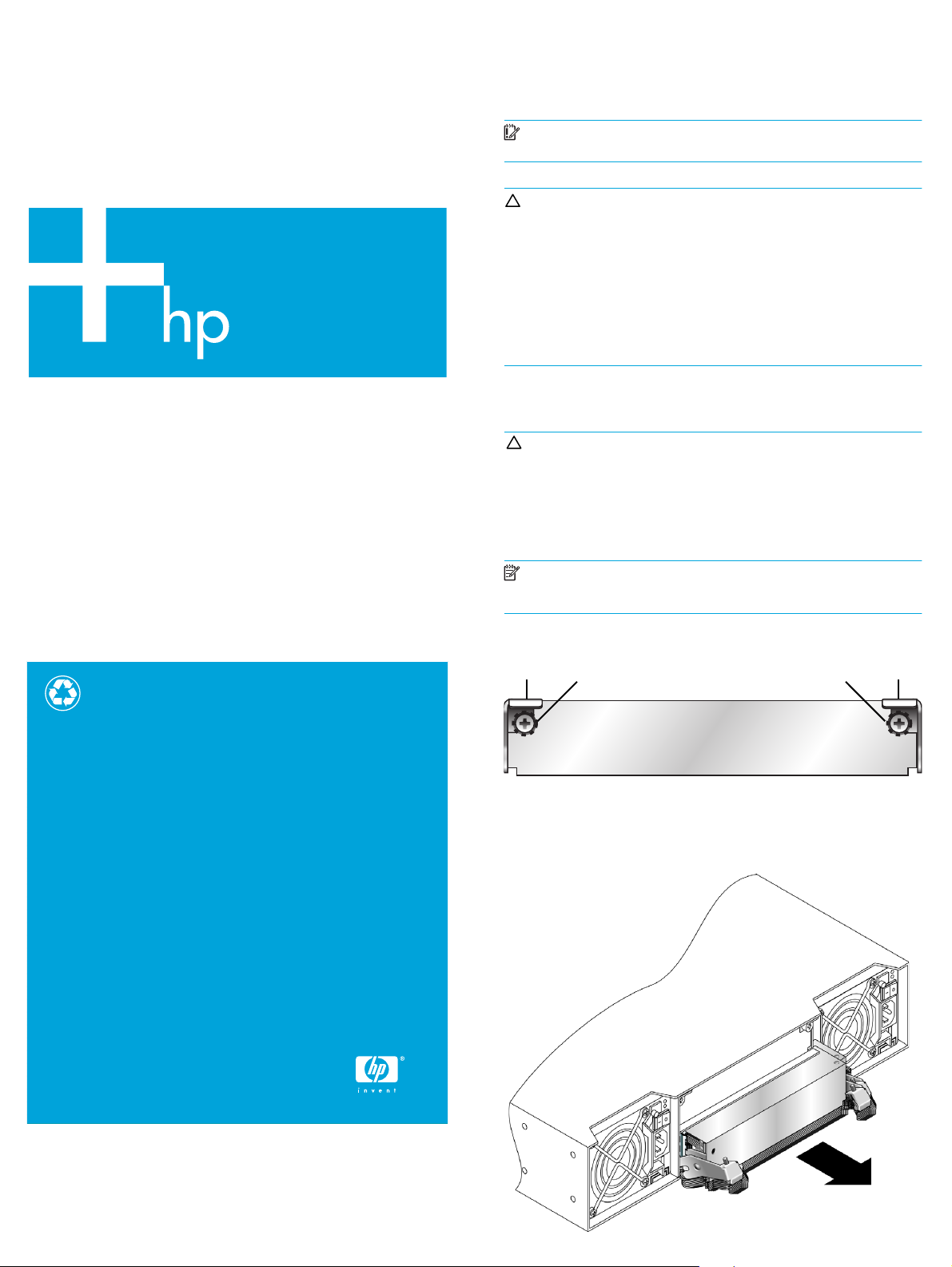
1. Turn the thumbscrews until the screws disengage from the blank.
Printed on at least 50% total recycled fiber with at least 10%
post-consumer paper
© Copyright 2008 Hewlett-Packard Development Company, L.P.
Second edition: November, 2008
Product names mentioned herein may be trademarks of their
respective companies as reflected by an associated footnote. The
information in this document is subject to change without notice.
Printed in China.
www.hp.com
1 Latch 2 Thumbscrew
2. Press both latches downward.
3. Pull the blank straight out of the enclosure.
481603-002
Page 1
Page 2
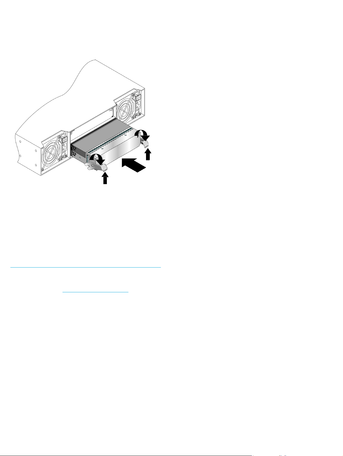
Installing the I/O module
2
1
2
1. Loosen the thumbscrews; press the latches downward.
2. Slide the I/O module into the enclosure as far as it will go (1).
3. Press the latches upward to engage the I/O module (2); turn the
thumbscrews finger-tight.
4. Connect cables according to a supported configuration. See the
user guide.
Verifying I/O module status
In an operational system, once the I/O module is installed and
cabled:
• Verify that the heartbeat LED on the front of the enclosure is
green.
• Verify that the OK LED on the back of the new I/O module is
green.
Additional information
See the MSA web site: http://www.hp.com/go/msa.
Page 2
 Loading...