

Page 1

HP StorageWorks
Library and Tape Tools User Guide
Product Version: 4.2
HP StorageWorks Library and Tape Tools (L&TT) is a comprehensive application that provides functions for identifying,
testing, updating, and troubleshooting a wide variety of data storage hardware and media.
*5697-6285*
Par t numbe r: 5697–6285
Seventeenth edition: (November 2006)
Page 2

Legal and notice information
© Copyright 2002-2006 Hewlett-Packard Development Company, L.P.
Hewlett-Packard Company makes no warranty of any kind with regard to this material, including, but not limited to, the implied
warranties of merchantability and fitness for a particular purpose. Hewlett-Packard shall not be liable for errors contained herein or
for incidental or consequential damages in connection with the furnishing, performance, or use of this material.
This document contains proprietary information, which is protected by copyright. No part of this document may be photocopied,
reproduced, or translated into another language without the prior written consent of Hewlett-Packard. The information contained in
this document is subject to change without notice.
Compaq Computer Corporation is a wholly-owned subsidiary of Hewlett-Packard Company.
Microsoft®, MS-DOS®, MS Windows®, Windows®, and Windows NT® are U.S. registered trademarks of Microsoft Corporation.
UNIX® is a registered trademark of The O pen Group.
Hewlett-Packard Company shall not be liable for technical or editorial errors or omissions contained herein. The information is
provided “as is” without warranty of any kind and is subject to change without notice. The warranties for Hewlett-Packard Company
products are set forth in the express limited warranty statements for such products. Nothing herein should be construed as
constituting an additional warranty.
Page 3

Contents
Aboutthisguide .......................... 11
Intendedaudience...................................... 11
Prerequisites ........................................ 11
Documentconventionsandsymbols ............................. 12
HPtechnicalsupport.................................... 13
Subscriptionservice .................................... 13
OtherHPwebsites..................................... 13
1Introduction............................ 15
Softwarefeatures ..................................... 15
Supportedproductsandoperatingsystems .......................... 16
Finding additional information . . . . . . . . . . . . . . . . . . . . . . . . . . . . . . . . 16
Gettingsupport ...................................... 16
2Installation............................ 17
InstallingL&TTforWindows................................. 18
UpgradingfromapreviousversionofL&TT ........................ 18
Windowsinstallationprerequisites ............................ 18
Installationprocedure ................................. 19
InstallingL&TTforNetWare................................. 20
NetWareinstallationprerequisites ............................ 20
Installationprocedure ................................. 20
InstallingL&TTforHP-UX,Tru64,andLinux .......................... 21
HP-UXinstallationprerequisites ............................. 21
Tru64installationprerequisites.............................. 21
Linuxinstallationprerequisites.............................. 22
Installationprocedure ................................. 22
Uninstallingpreviousversions ............................ 22
Installingthelatestversion.............................. 22
InstallingL&TTforHPOpenVMS............................... 24
OpenVMSinstallationprerequisites............................ 24
Installationprocedure ................................. 24
3GettingStartedwithL&TT..................... 25
StartingL&TT(GUI) .................................... 25
UsingtheScanModeSelectionfeature............................ 25
Scanmode...................................... 26
UsingtheSaved/ManualScanscreen ........................ 27
Additionaldevicescanconsiderations ........................ 27
I/Omode ...................................... 28
Skipthisdialoginthefuture............................... 28
Applicationwindowlayout ................................. 29
UsingtheDeviceInformationscreen ............................. 30
Standalonedevices .................................. 31
Libraryandautoloaderproducts............................. 32
UsingtheFirmwareManagementscreen ........................... 34
UsingtheTestsscreen ................................... 35
UsingtheSupportTicketGenerationscreen .......................... 36
StartingL&TT(CSI)..................................... 36
Library and Tape Tools User Guide
3
Page 4

Navigatingthescreens................................... 38
UsingtheScanModeSelectionscreen ............................ 39
UsingtheSaved/ManualScanscreen ............................ 40
UsingtheDeviceInformationscreen ............................. 40
Standalonedevices .................................. 41
Libraryandautoloaderproducts............................. 42
4 Firmware Management . ..................... 43
Accessing firmwarerevisionandreleasenoteinformation(GUI).................. 43
Acquiring firmware files(GUI)................................ 44
UsingtheGetFilesfromWebfunctionality(GUI)...................... 44
AccessingtheGetFilesfromWebdialogbox ..................... 44
Selecting and downloading updated firmware files................... 45
Viewing firmwarerevisionhistory........................... 46
Uploading firmwaretodevices(GUI)............................. 46
Advancedoptions(GUI) .................................. 47
Acquiring firmware files(CSI) ................................ 48
UsingtheGetFilesfromWebfunctionality(CSI) ...................... 48
Uploading firmwaretodevices(CSI) ............................. 49
Advancedoptions(CSI)................................... 49
Using a firmwareupdate(FUP)tape ............................. 50
Performing the update . . . . . . . . . . . . . . . . . . . . . . . . . . . . . . . . . 50
SDLT....................................... 50
DLTVS80/DLT1.................................. 51
DLT4000/7000/8000............................... 52
Ultrium...................................... 53
HPDDS/DAT................................... 54
Compaq/Sony AIT & DDS . . . . . . . . . . . . . . . . . . . . . . . . . . . . . 55
Converting a firmware update tape to a data tape . . . . . . . . . . . . . . . . . . . . . 55
5Testsandutilityfunctions..................... 57
Runningthetests(GUI)................................... 58
Viewingtestresults................................... 58
Runningthetests(CSI) ................................... 58
Viewingtestresults(CSI) ................................ 58
Testdescriptions...................................... 59
Performancetests ................................... 59
Diagnostictests .................................... 59
Acceptancetest.................................. 60
Assessmenttest .................................. 60
AutoloaderExercisertest .............................. 63
CompareStatisticstest ............................... 64
Connectivitytest.................................. 65
DAT autoloader firmwaretapecreator ........................ 66
DataCompressiontest ............................... 67
DeviceAnalysistest ................................ 68
Device Configurationtest .............................. 69
DeviceSelf-Test .................................. 70
DLTSRAMChecktest(shortandlongversions)..................... 71
ESLVendorIDtest................................. 71
FirmwareTapeCreator(FUPtape)test ........................ 72
ForceTapeEjectutility ............................... 72
FullSweeptest .................................. 73
InitializeElementStatustest ............................. 74
InstallationChecktest ............................... 75
LibraryExercisertest ................................ 76
LTOCoolingChecktest............................... 76
LTOFirmwaretoDataTapeCreator ......................... 77
LTOMediaAssessmenttest ............................. 77
4
Page 5

LTOStuckTapetest................................. 79
MediaAnalysistest ................................ 80
MediaErasetest.................................. 81
MediaValidationtest................................ 82
MOMediaValidationtest ............................. 82
Movetest..................................... 83
ReadMediaIDstest ................................ 84
Read/WriteStresstest ............................... 84
Read/Writetest.................................. 85
RestoreFactoryDefaultSettings ........................... 86
SDLTTapeEdgeDamage(TED)test.......................... 87
UsingtheDrivePerformancetest............................... 88
UsingtheSystemPerformancetest .............................. 92
PerformingtheSystemPerformanceRestorePre-Test(GUI) .................. 92
PerformingtheSystemPerformanceBackupPre-Test..................... 93
PerformingtheSystemPerformancePre-Tests(CSI)...................... 95
UsingtheDeviceAnalysistest................................ 96
UsingtheRead/Writetest.................................. 97
UsingtheMovetest .................................... 97
UsingtheMediaAnalysistest ................................ 98
UsingtheLibraryExercisertest................................ 98
Usingthenewversion ................................. 98
Usingtheoriginalversion................................ 99
Usingtheutilityfunctions .................................. 100
6Reportsandsupporttickets.................... 103
Usingareportorsupportticket(Windows) .......................... 104
UsingtheSupportscreen................................ 104
Reportandsupportticketcompression ........................ 105
Viewingareportorsupportticket ............................ 106
Settingthedetaillevel ............................... 106
Otherfunctionality................................. 106
Viewingembeddeddata .............................. 107
Savingareportorsupportticket............................. 108
Sendingareportorsupportticketbye-mail ........................ 108
Comparingreportsorsupporttickets ........................... 110
Interpretingareport .................................. 111
Understandingthemarginratings .......................... 111
Thingstolookfor ................................. 112
Device-specificreportanalysis.............................. 113
LTOdrives .................................... 113
LTOmedia .................................... 114
Generatingandviewingasupportticket(CSI) ......................... 115
Supportticketcompression ............................... 116
Sendingasupportticketbye-mail(CSI).......................... 116
Loadingoropeningsupporttickets.............................. 117
UsingXMLsupporttickets.................................. 117
GeneratinganXMLsupportticket(GUI).......................... 117
GeneratinganXMLsupportticket(CSI).......................... 118
Commoninformationreportedforallproducts ......................... 118
Usingtheeventlog .................................... 119
Generatinganeventlog(Windows) ........................... 119
Generatinganeventlog(CSI).............................. 119
7CommandLineFunctionality ................... 121
Overview......................................... 121
Commandlinefunctions .................................. 121
ConfiguringL&TT ................................... 122
Scanningthebus ................................... 122
Library and Tape Tools User Guide
5
Page 6

Runningtests ..................................... 123
Performing a firmware update . . . . . . . . . . . . . . . . . . . . . . . . . . . . . . 124
Generatingareportorsupportticket........................... 126
Gettingusagehelp .................................. 126
Returnvalues ....................................... 127
Using th e trace file................................... 127
8AdditionalFunctionality ..................... 129
Settingsoftwarepreferences................................. 129
Availableoptions ................................... 131
UsingtheInternetupdatefunctionality ............................ 131
Usingpasswords ..................................... 132
Settingpasswords................................... 132
UsingtheFrontPanelfunction ................................ 133
UsingtheMoveMediafunction ............................... 133
PossibleMoveMediaerrorsituations........................... 134
Performing manual product identification ........................... 135
UsingtheQuietModefeature................................ 135
UsingtheInstallationCheckfeature.............................. 136
UsingL&TTinrestrictedmode ................................ 138
UsingtheToolStatusReport................................. 139
9AdvancedInstallationTopics ................... 141
Otherchangestothesystem(GUI).............................. 141
Rebootcriteria....................................... 141
Running L&TT from a CD-ROM or USB flashdrive........................ 141
Filesinstalledonthesystem................................. 142
Otherchangestothesystem(CSI) ............................ 142
10FrequentlyAskedQuestions ................... 143
Generalquestions..................................... 143
WhyshouldIrunL&TTtests? .............................. 143
Where can I find information about media compatibility with my hardware? . . . . . . . . . . 143
Where can I find information about hardware and software compatibility? . . . . . . . . . . . 144
Where can I findinformationaboutdrivecleaningrequirements?............... 144
HowdoIinstallL&TT? ................................. 145
How do I use L&TT to findmydriveserialnumber? ..................... 145
How do I verify that my drive’s firmwareisuptodate? ................... 145
HowdoIcheckifmydriveisOK?............................ 145
WhyistheAssessmenttestrecommended? ........................ 145
IsmyLTOtapeOK? .................................. 146
Ismynon-LTOtapeOK? ................................ 146
Wasmybackupsuccessful(LTOonly)? .......................... 146
Howmanymoreusesareleftinthiscleaningcartridge(LTOonly)? .............. 146
Howfastwillmybackupsbe?.............................. 146
Howfastwillmyrestoresbe? .............................. 147
How do I verify the capacity of a tape? . . . . . . . . . . . . . . . . . . . . . . . . . . 147
HowdoIsendasupportticket? ............................. 147
HowdoIsendanL&TTeventlog?............................ 147
Windowsquestions .................................... 148
How do I run L&TT from a CD-ROM or USB flashdrive?................... 148
HowdoIshutdowntheapplicationinthetaskbar?..................... 148
When installing L&TT for Windows, should I uninstall my previous version first? ......... 149
Whycan’tIuninstallL&TTorinstallanewversion?..................... 149
HowdoIeraseanLTOFUPtape? ............................ 149
How do I configuree-mailtosendsupporttickets? ..................... 149
DoesL&TTuseanysystemresourcesinthebackground?................... 150
6
Page 7

I am using an authenticated proxy at my site. How do I configure L&TT to connect to the HP website to
download firmware updates? . . . . . . . . . . . . . . . . . . . . . . . . . . . . . . 150
L&TT starts in “restricted” mode and most functionality is unavailable. What is happening? . . . . 150
Why doesn’t L&TT for Windows “see” devices that are connected to a computer running HP-UX? . 150
Whydoesn’tL&TTforWindows“see”myUSBdrives?.................... 150
CSIquestions....................................... 151
HowdoIsetthepassword?............................... 151
Why does my display not show any text or only a single line of text on my HP-UX system? . . . . 151
Whydoesn’tL&TTforHP-UX“see”someofmydevices?................... 151
Why am I unable to download firmware/script files using the download option in the CSI (HP-UX,
Linux)?........................................ 152
Whydoesn’tL&TTforTru64“see”someofmydevices?................... 152
Whydoesn’tL&TTforLinux"see"someofmydevices? ................... 152
Why doesn’t L&TT for Windows “see” devices that are connected to a computer running HP-UX? . 153
HowdoIdisconnectaSCSIdeviceinTru64? ....................... 153
HowdoIconnect/disconnectaSCSIdeviceinLinuxwithoutrebooting?............ 153
Whydoesn’tL&TTforOpenVMS“see”mymediachanger? ................. 153
Why am I getting "Error a ctivating image PTHREAD$RTL" while running L&TT on OVMS 7.3-1? . . 153
11 Troubleshooting . . . ..................... 155
TroubleshootingL&TT.................................... 155
Troubleshootingdevices................................... 155
UsingL&TTtotroubleshoottapedevices.......................... 155
Areyouperformingregularmaintenance?....................... 156
Isthedriveconnectedproperly?........................... 156
Isthedriveworkingasexpected? .......................... 156
Is the drive firmwareuptodate?........................... 157
Isthedriveperformingasexpected? ......................... 157
Isthemediaingoodcondition? ........................... 157
Knownissues..................................... 157
Deviceaccessissues(RSMonWindows) ....................... 157
Deviceperformanceissues ............................. 158
FirmwareissueswithUltriumdrives.......................... 159
Additionalinteractivedevicetroubleshootingcontent .................... 159
Troubleshootingthird-partysoftware ............................. 159
Backupfailed..................................... 159
Index .............................. 161
Library and Tape Tools User Guide
7
Page 8

Figures
1
..
2
..
3 ..
4
..
5
..
6
..
7
..
8
..
9
..
10
..
11
..
12
..
13
..
14
..
15
..
16
..
17
..
18
..
19
..
20
..
21
..
22
..
23 ..
..
24
25
..
26
..
27
..
28
..
29
..
30
..
31
..
32
..
33
..
34
..
35
..
L&TTsplashscreen ............................... 26
Saved/ManualScanscreen ........................... 27
L&TTmainscreen................................ 29
Compatibledatacartridgesscreen ........................ 32
DeviceInformationscreenshowingalibrary .................... 32
FirmwareManagementscreen .......................... 34
Testsscreen .................................. 35
SupportTicketGenerationscreen......................... 36
CommandHelpscreenaccessedfromtheMainscreen................ 38
ScanModeSelectionscreen........................... 39
Saved/Ma
CSIMainscreen ................................ 40
DeviceInformationscreenforastandalonedevice.................. 41
DeviceInformationscreenforalibrary....................... 42
GetFilesfromWebdialogbox—Firmwaretab ................... 45
FirmwareUpdatescreen............................. 46
FactoryFirmwareOverridesdialogbox ...................... 47
DrivePerformancescreen ............................ 89
Device P
RestorePre-TesttaboftheSystemPerformancescreen ................ 92
BackupPre-TesttaboftheSystemPerformancescreen ................ 94
BackupPre-Testscreen(CSI) ........................... 95
Restor
Supportscreen................................. 105
Examplereport................................. 106
Supportticketwithembeddeddata........................ 107
E-ma
Supportticketcomparisonresults ......................... 111
L&TTPreferencesdialogbox(defaultsettingsshown)................. 130
L&TTpreferencesdialogbox(CSIversion) ..................... 130
Fron
MoveMediascreen............................... 134
InstallationCheckwizard ............................ 137
ToolStatusReportscreen(GUI).......................... 139
ToolStatusReportscreen(CSI) .......................... 140
nualScanscreen(CSI)......................... 39
erformanceToolscreen.......................... 90
ePre-Testscreen(CSI) ........................... 96
ilsupportticketdialogbox.......................... 109
tpanelscreen ............................... 133
8
Page 9

Tables
1
2
..
Documentconventions.............................. 12
..
L&TTinstallationdirectorylocations........................ 142
Library and Tape Tools User Guide
9
Page 10

10
Page 11

About this guide
This user guide provides information to help you:
• Understand features and functionality of L&TT
• Effectively use the full functionality of L&TT to o b tain maximum performance from your storage
hardware, and to test, diagnose, and resolve hardware issues
“About this Guide” topics include:
• Overview
• Conventions
• Getting Help
Intended audience
This book is intended for:
to use L&TT to conveniently update firmware in their storage hardware
• Users who wan
• Users who need to test, diagnose, and resolve storage hardware issues
• Support technicians
• Call center
t
personnel
Prerequisites
Before you attempt to use L&TT, you should have a basic understanding of the following technologies:
• Storage hardware functionality and operation
• SCSI operation
Library and Tape Tools User Guide
11
Page 12

Document conventions and symbols
conventions
Table 1 Documen
t
Convention
Blue text: Table 1
Blue, underlin
www.hp.com
Bold text
Italic text Text emphasis
Monospace text
Monospace, italic text
Monospace, bold text
ed
text: h
ttp://
Element
Cross-reference links and e-mail addresses
Website addresses
• Keys that are pressed
Text typed into a GUI element, such as a box
•
GUI elements that are clicked or selected, such as menu and
•
list items, buttons, tabs, and check boxes
• File and directory names
System output
•
•
Code
Commands, their arguments, and argument values
•
• Code variables
Command variables
•
Emphasized monospace text
WARNING!
Indicates that failure to follow directions could result in bodily harm or death.
CAUTION:
Indicates that failure to follow directions could result in damage to equipment or data.
IMPORTANT:
Provides clarifying information or specific instructions.
NOTE:
Provides additional information.
TIP:
Provides helpful hints and shortcuts.
12
About this guide
Page 13

HP technical support
Telephone numbers for worldwide technical support are listed on the HP suppor t website:
http://www.hp.com/support/.
Collect the f
• Technical support registration number (if applicable)
• Product serial numbers
• Product mod
• Error messages
• Operating system type and revision level
• Detailed q
For continuous quality improvement, calls may be recorded or monitored.
ollowing information before calling:
el names
uestions
and numbers
Subscription service
HP strongly recommends that customers register online using the Subscriber’s choice website:
h
ttp://www.hp.com/go/e-updates.
Subscribing to this service provides you with e-mail updates on the latest product enhancements, newest
driver versions, and firmware documentation updates as well as instant access to numerous other product
resources.
After subscribing, locate your products by selecting Business support and then Storage under Product
Category.
Other HP websites
For addi
• h
• http://www.hp.com/go/storage
• http:/
• http://www.docs.hp.com
• http://www.hp.com/support/tapetools
• http:
tional information, see the following HP websites:
ttp://www.hp.com
/www.hp.com/service_locator
//www.hp.com/support/lttcompatibility
Library and Tape Tools User Guide
13
Page 14

14
About this guide
Page 15

1Introduction
HP StorageWorks Library and Tape Tools (L&TT) is a collection of storage hardware management and
diagnostic tools for Nearline Tape, Nearline Tape Automation, and Nearline Archival products. L&TT
assembles these tools into a single, convenient p rogram.
IMPORTANT:
This user guide is intended for L&TT version 4.2. Certain features from previous versions of L&TT are no
longer supported with this version and are therefore not documented here. HP strongly recommends
that you install and use the latest version of L&TT. However, if you must use an earlier version, refer to
the online help that is bundled with that version of the program.
Software features
L&TT offers the following features:
• Installation Check—L&TT guides you through a basic installation check of your product. The
software assists the user in choosing an appropriate HBA and SCSI IDs, ensuring that the device
is
detected by the system, and verifying key device functionality.
• Device Identification—L&TT clearly identifies the storage products connected to the system, along
with key information on product configuration and status.
• Troubleshooting Tests—L&TT provides various tests to verify product functionality or to isolate
product issues. Tests include device self-tests, read/write tests on drives, exerciser tests for
autoloaders and libraries, and specific device utilities.
• Firmware Upgrades—L&TT provides a convenient way of updating product firmware, enabling
users with an Internet connection to take advantage of ongoing enhancements. The software can
be
configured to check the Web automatically for firmware updates for connected devices, or
users can manually check the Web for updates if the automatic update feature is not desired.
If
updated firmware is available, the program notifies the user, and the updates can easily be
copied to the system. With libraries, users can upgrade the library and the embedded drive
firmware in thesameoperation.
• Support Ticket Generation—If you experience a problem with a storage product, L&TT can
generate a suppor t ticket that includes essential information for troubleshooting the problem.
As an
alternative to phone support, you can e-mail the support ticket to a support center for
assistance. This information streamlines the support process and enables the suppor t staff to
better serve you if a support call is made later.
When a support ticket for a device is generated, L&TT performs a Device Analysis test on the device.
The s upport ticket contains generic information about a device, as well as the results of the Device
Analysis test. The Device Analysis test can be performed by itself, but HP recommends generating a
support ticket because the resulting data is presented in a more useful format.
• Automatic Notification of Web Updates—If a connection to the Internet is present and web
updates are enabled in the tool preferences, L&TT automatically informs you of the following
updates, if available, each time the program is started:
•New versions of L&TT
•New firmware files for connected devices
• New device-specific functionality for connected devices
Library and Tape Tools User Guide
15
Page 16

Supported products and operating systems
For a complete listing of compatible products, refer to the specifications page at
h
ttp://www.hp.com/support/lttcompatibility.
The level of fun
and the degree o
ctionality that L&TT offers for each device varies depending on features of the device,
device integration into L&TT.
f
Finding additional information
The HP website provides the current version of L&TT for download, and general information about the
tool. Access the website at:
http://www.hp.com/support/tapetools
Getting support
E-mail support is available from ltt_team@hp.com. You can expect a response within 24 hours (usually
sooner) during a normal business week.
Use this address to obtain support for L&TT to report bugs, to provide feedback on this manual, to report
any issues with the L&TT website, or to provide enhancement suggestions. HP appreciates feedback on
how to make improvements for future versions of L&TT.
NOTE:
is intended to provide support for L&TT software. This address is
This addres
troubleshooting hardware products. Refer to the documentation that comes with your hardware for
support
s
options for that product.
not
for assistance in
16
Introduction
Page 17

2 Installation
This chapter outlines the procedure for installing L&TT on a Microsoft® Windows®, Novell NetWare,
HP-UX, HP Tru64, Linux, or HP OpenVMS platform. The Windows version of L&TT uses a graphical user
interface (GUI). All other versions of the program use a command screen interface (CSI).
The information in this chapter and in subsequent chapters is presented for both the GUI and CSI versions
of L&TT. When using an electronic version of this documentation, click the appropriate link at the
beginning of the chapter to quickly jump to the section of documentation that applies to your op erating
system (OS) or user interface.
Select your OS:
Installing L&TT for Windows
Installing L&TT for NetWare
Installing L&TT for HP-UX, Tru64, and Linux
Installing L&TT for HP O penVMS
Library and Tape Tools User Guide
17
Page 18

Installing L&TT for Windows
The Windows version of L&TT uses the InstallShield application. InstallShield lets you choose the
installation directory and select other options. It also sets up shortcuts to launch the application in the
on the desktop. The Start menu shortcuts also provi de access to the online help, the
Start menu an
readme
Upgrading from a previous version of L&TT
Beginning with version 4.0, the L&TT installer automatically uninstalls any previous versions before
installing the current version, so it is not necessary to ma nually uninstall your previous version.
Windows installation prerequisites
Download link http://www.hp.com/support/tapetools
Install time (typical) 1-5 minutes
d
file, the report viewer, and the L&TT Installation Check feature.
Reboot re
ments
Software dependenc
sites
quire-
ies/prerequi-
required only if your system requires ASPI or an upgrade
A reboot i
to
the cu
installer detects a previously installed version of ASPI older than v4.57,
it will install a more recent version of ASPI, which will require a reboot.
On Windo
system
option in the installation process. If you choose not to install ASPI, you must
use the Miniport driver (Miniport I/O mode) to scan for devices.
Issues
that
the
may be necessary to shut down any running backup/storage application
servi
ASPI I
her
furt
Device drivers for the connected tape devices/libraries or default
devi
NOTE
L&TT
L&T
s
rrently installed version. On systems that require ASPI, if the
ws NT and 2000, ASPI is not installed as part of the operating
If a reboot is unacceptable, do not select the checkbox for this
.
may arise, however, when using the Miniport I/O mode with devices
use non-standard OS drivers, or are “claimed” by other applications or
OS. When using the Miniport I/O mode when a device is claimed, it
ces to make the device accessible to L&TT. Alternatively, using the
/O modemay make thedeviceaccessiblewithout requiring any
action.
driver should be present.
ce
:
can be run from a CD ROM or USB flash drive. See "Running
TfromaCD-ROM or USB flash drive"on page 141.
Known issues When downloading the L&TT application from the Web to your local
system, make sure you name the download folder to something other
than HP StorageWorks Library and Tape Tools or the
installation will fail if you attempt to install from that folder. The failure
error will indicate that a different instance of the installer is already
running.
Also, do not rename the L&TT installation file. Renaming the file may create
aconflictthatpreventsL&TT from installing.
18
Installation
Page 19

Installation pr
To install the current Windows version of L&TT:
1. Download or cop
IMPORTANT:
Do not rename th
2. Double-click the self-extracting executable file to launch the installer. The InstallShield Wizard
screen is displayed.
3. Click Next. Read the program license agreement and click Yes if you agree to and accept
the
4. Read the readme file for any last-minute changes to the documentation, then click Next.The
Select Features screen is displayed.
5. Select the d esired components to install and click Next.
In most cases, the default settings of this screen are adequate. Windows NT 4.0®, Windows 2000,
and
support. HP does not recommend installing ASPI support unless you have a good reason to do so.
ASPI support is beneficial when installed storage applications cannot be shut down, and those
applications have locked access to the device through the Miniport driver. If ASPI is installed, it is
generally not necessary to shut down these applications to access devices through L&TT (although
the
on a
using ASPI is not realized the firsttimeL&TTisrun,but it is realized on subsequent runs.
ocedure
the self-extracting executable file to a temporary location.
y
file. Renaming the file may create a conflict that prevents L&TT from installing.
is
terms of the license agreement.
Windows XP users have the option to install Advanced SCSI Programming Interface (ASPI)
applications should not be accessing the devices while L&TT is running). ASPI lets you run L&TT
locked device without rebooting, but a reboot is required after installing ASPI. The benefitof
One drawback of ASPI is that USB drives are not supported. If you have USB drives, you must
use the Miniport driver.
Beginning with version 4.0, L&TT supports Microsoft Storport technology. Storport is a new storage
driver model created by Microsoft for Windows Server 2003 and future Windows® operating
systems. Storport offers a higher performance architecture and better Fibre Channel compatibility
in Windows systems. If Storport drivers are installed, L&TT automatically uses Storport when you
select Miniport I/O.
NOTE:
ASPI is not officially supported by Windows Server 2003. However, in most cases, it will function
properly. If ASPI is installed with Windows Server 2003, L&TT can make use of it if the ASPI I/O
mode is selected. However, HP recommends that you use the default NT MiniPort I/O option
with Windows Server 2003.
6. Select a destination location to install the program. You can accept the default location or click
Browse to install to a different location. After choosing the destination location, click Next.
7. Indicate the program directory in which you want the setup program to create program icons
and
click Next. The program directory is created in the Programs directory of the Start menu.
8. On the Ready to start installation process screen, click Next. If you need to review or change
installation settings, click Back.
9. When installation is complete, the InstallShield wizard displays its final screen.
Select
Start HP L&TT or Run LTT InstallCheck if you would like the wizard to start
Library and Tape Tools User Guide
19
Page 20
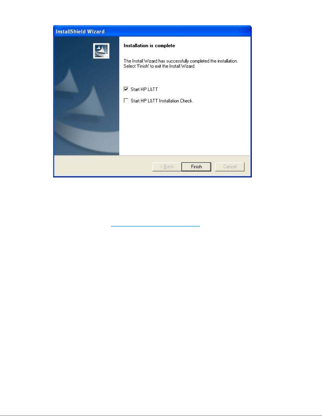
L&TT or the Installation Check test.Click Finish to close the InstallShield wizard.
Installing L&TT for NetWare
NetWare
Installation procedure
installation prerequisites
Downloa
Install time (typical) Less than 2 minutes
Reboot require- None
ments
Software depen- • Deviceshouldberecognizedbythe NWPA subsystem.
dencies/prerequisites
Known issues None
To install the NetWare version of L&TT:
dlink
http://
• Device drivers for the connected tape devices/libraries or default
•L&TT
www.hp.com/ support/tapetools
device driver should be present.
gurations.
confi
NetWare currently does not support clustering
on
1. Download the L&TT for NetWare file to a temporary directory.
20
Installation
Page 21

2. From a client workstation, use any standard unzip utility* to extract the file to the SYS:System\
directory on the NetWare server. Make sure that the option to create a directory is enabled
in the
archiving software.
NOTE:
* The unzip NLM that comes with later versions of NetWare has not been tested and should not be
used to unzip the archive.
Installing L&TT for HP-UX, Tru64, and Linux
HP-UX installation prerequisites
Download link http://www.hp.com/support/tapetools
Install time (typical) Less than 3 minutes
Reboot require- None
ments
Software depen- •
dencies/prerequisites
• The sctl driver must be installed for L&TT to access the device you
• Devices must NOT be listed as "NO HARDWARE" in ioscan. If the
Known issues To install L&TT, you must first uninstall any previous versions.
Tru64 installation prerequisites
Download link http://www.hp.com/support/tapetools
Install time (typical) Less than 3 minutes
Devices do not need to be claimed by the operating system with
ioscan for L&TT to access them.
want to test. L&TT builds its own pass-through SCSI device files
using the sctl driver, so that driver must be installed; however, L&TT
does not need the operating system to list any of the devices as
"CLAIMED." They maybelistedthatway (ifthe appropriatedriver
is
installed), but they don’t need to be for L&TT to fully access them
(beginning
device you want to test with L&TT is listed as "NO HARDWARE" in
ioscan, the communication path between the host and the device
is not
communicate with the device.
with L&TT v3.3).
working and must be fixedbeforeL&TTwillbe ableto
Reboot require- A reboot occurs only if hardware manager failed to recognize the
ments connected device.
Software depen- • Device should be recognized by Hardware Manager and SCU
dencies/prerequi- subsystem.
sites
• Device drivers for the connected tape devices/libraries or default
device driver should be present.
Library and Tape Tools User Guide
21
Page 22

Known issues None
Linux installation prerequisites
Download link http://www.hp.com/support/tapetools
• L&TT on Tru64 UNIX currently does not support clustering
configurations.
Install time
Reboot require- None
ments
Software depen- •
dencies/p
sites
Known issues To install L&TT, you must first uninstall any p revious versions.
(typical)
rerequi-
Installation procedure
Uninstalling previous versions
Before installing L&TT on Linux or H P-UX, you must first uninstall any previous versions.
Uninstalling HP-UX version
To determine if L&TT is already installed, use the following command:
swlist | grep ltt
To remove a previous version of L&TT, use the following command:
swremove HP_LTT<xx>
Less than 3 mi
Deviceshouldberecognizedbyproc/SCSI subsystem.
• Device drivers for the connected tape devices/libraries or default
device dri
nutes
ver should be present.
where <xx>isthe versionnumber.
Uninstalling Linux version
To determine if L&TT is already installed, use the following command:
rpm -qa | grep ltt
previous version of L&TT, use the following command:
To remov
rpm -e ltt
e a
Installing the latest version
To install L&TT for HP-UX, Tru64, or Linux:
1. Log in as root.
2. Navigate to the temporary directory:
cd /tmp
22
Installation
Page 23

3. Download or copy the L&TT tar file, hp_ltt<xx>.tar (where <xx>isthe versionnumber) to
this directory. If you are copying the file from a different location, enter the following (substitute
the
directory in which the file currently resides for <directory name>):
cp /<directory name>/hp_ltt<xx>.tar /tmp
NOTE:
The Tru64 tar filename uses the letter “o” in place of zeroes. For L&TT 4.2, the filename is
hp_ltt42.tar.
4. Un-tar the L&TT tar file:
tar -xvf hp_ltt<xx>.tar
5. Run the install script in the /tmp directory:
./install_hpltt
NOTE:
For Linux, the L&TT installer verifies that the operating system you are installing on is supported.
If
the Linux distribution or release is unsupported, the install script displays a message indicating
an installation failure and lists the supported operating systems.
6. After the software is successfully installed, enter the following commands to remove the
/tmp/ltt
directory and its contents:
cd /tmp
rm -rf ltt
rm -rf install_hpltt
Library and Tape Tools User Guide
23
Page 24

Installing L&TT for HP OpenVMS
OpenVMS installation prerequisites
Download link http://www.hp.com/support/tapetools
Install time (typical) Less than 4 minutes
Reboot requirements
Known issues None
Installation procedure
NOTE:
with version 4.1, L&TT is only supported on OpenVMS v 7.3-2 and OpenVMS 8.2 Alpha.
Beginnin
1. Download or copy the install file hp-axpvms-ltt-v<xx>-1.pcsi (where <xx> is the version
2. Navigate to the directory you copied the install file to and enter the following c om m and to
3. Set the term to vt100 using the following command:
4. Define the logical name USR so that it points to the directory sys$sysdevice:[vms$com-
g
number) to a temporary directory.
install L&TT:
product install
The installation procedure creates the directory structure opt.ltt in sys$sysdevice:[vms$com-
mon] and installs a ll the required files for L&TT.
set term /dev=vt100
mon.opt.ltt.misc.usr] using the following command:
define usr sys$sysdevice:[vms$common.opt.ltt.misc.usr]
None
24
Installation
Page 25

3 Getting Started with L&TT
This chapter describes how to start L&TT and the basic operation of the software. This chapter is divided
into
two sections: one for using L&TT in a GUI environment (Windows) and one for using L&TT in a
CSI environment (NetWare, HP-UX, Tru64, Linux, and OpenVMS). To quickly jump to the appropriate
section, click one of the following links:
Starting L&TT (GUI)
Starting L&TT (CSI)
Starting L&T
To start L&TT, do one of the following:
• Double-click the L&TT icon on the desktop (if present).
• Click Start >
T(GUI)
Programs > HP StorageWorks Library and Tape Tools > HP L&TT.
Using the Scan Mode Selection feature
When L&TT starts, the splash screen opens. The splash screen gives you the o pportunity to exit the
application if it was started unintentionally and before any SCSI bus activity occurs. This prevents the
program from interfering with any backup or other storage applications that currently may be running.
Library and Tape Tools User Guide
25
Page 26

Figure 1 L&TT splash screen
The splash screen also lets you select the initial scan mode and the SCSI I/O mode (if more than one
option is available).
Scan mode
When L&TT
directly or through a SAN. In large SAN environments, a full scan can take a long time. The first time
L&TT is run, it must perform a full hardware scan (Hardware Scan option). After that i s done, the results
of the
can
list of available d evices will be empty.
NOTE:
If you previously selected the Skip this dialog in the future checkbox on the splash screen, L&TT performs
a
full hardware scan. To re-enable the splash screen and change the scan option, select Preferences from
the Opt
Select multiple devices to be scanned from the Saved/Manual Scan screen. In addition, automatically
save device selections and reuse them in a later session.
To access the Saved/Manual Scan screen, select the Saved/Manual Scan option and click Continue
on the
starts, it performs a device scan to identify all the devices connected to the computer, either
scan a re automatically saved, so the next time L&TT is started, the Saved/Manual Scan option
ed. If the Saved/Manual Scan option is selected before a hardware scan is done, the
be us
ions menu. Check the Display splash screen at startup option and restart L&TT.
splash screen.
26
Getting Started with L&TT
Page 27
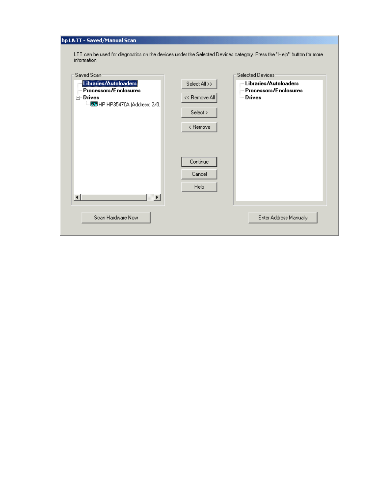
Figure 2 Saved/Manual Scan sc reen
Using the Saved/Manual Scan screen
The left panel of the Saved/Manual Scan screen d isplays the devices that were detected in the last saved
scan. If this list is incomplete (for example, if new hardware has been added since the last scan), click
Scan Hardware Now to rescan the system for new devices. If you want to m anually add a device to the
list of devices to be scanned without performing a full hardware scan, click Enter Address Manually.
Use the Select All, Remove All, Select,and Remove buttons to select devices. Selected devices are
displayed in the right panel of the screen, and only selected devices will be scanned and identified by
L&TT. Devices that are skipped will not be displayed in the Device List on the L&TT main screen.
After selecting all of the devices that you want L&TT to scan and identify, click Continue to perform the
scan and proceed to the L&TT main screen. L&TT saves the list of selected devices so the next time you
start L&TT and display the Saved/Manual Scan screen, L&TT displays all of the previously selected
devices in the right panel.
Additional device scan considerations
After the initial scan is complete and saved, future full system hardware scans become unnecessary in
most cases. You must perform a hardware scan after any of these actions have occurred (Windows in
NT
Miniport I/O mode of operation):
• After the hardware configuration has been changed
• After power cycling more than one of the tape drives on the system
• After updating firmware in more than one of the tape drives on the system
To perform a hardware scan, exit and restart L&TT. On the splash screen, select the Hardware scan option
rather than Saved scan. If you do not do this, the Windows operating system might get out of sync with the
L&TT saved scan because Windows device rediscovery assigns new logical device names to the devices.
Library and Tape Tools User Guide
27
Page 28

Also, if you power cycle or update firmware in a device while using a saved scan, the device may not be
accessible untilitisrediscoveredbyWindows. Ifyou select the devicebeforeitisrediscovered, L&TT
generates an error. After Windows has rediscovered the device, the device can be selected without
causing an error.
If you are running in saved scan mode and want to rescan the bus for devices, clicking the Rescan button
on the
choose the hardware scan option on the splash screen to execute a hardware scan.
I/O mode
L&TT selects
However, thi
operates in the following two I/O modes:
• NT Miniport—uses an interface that is native to Windows NT 4.0, 2000, XP, and Windows
• ASPI—uses an optional I/O programming interface that is available on all versions of Windows.
Scan tab of L&TT does not initiate a hardware scan. You must exit and restart L&TT, and then
input/output (I/O) mode that is most appropriate for the system it is running on.
the
initial screen allows for manual selection of the I/O mode in certain cases. L&TT currently
s
Thisisthe preferredI/O mode on systemswhere it is available because it does not
Server 2003
require the installation of the ASPI interface. However, there are some limitations to the Windows
NT
Miniport I/O mode related to using devices that are “claimed” by other applications, or
that are used with non-standard OS drivers. In those cases, selecting the ASPI I/O mode can
make a devi
Beginning with version 4.0, L&TT supports Microsoft Storport technology. Storport is a new storage
driver m o d el created by Microsoft for Windows Server 2003 and future Windows® operating systems.
Storport offers a higher performance architecture and better Fibre Channel compatibility in Windows
systems. If Storport drivers are installed, L&TT automatically uses Storport when you select NT Miniport.
This I/O mode can be used with any Windows operating system. It may require the installation or
update of additional OS components, possibly requiring a reboot of the system during installation.
.
accessible.
ce
NOTE:
ASPI is not officially supported by Windows Server 2003. However, in most cases, it will function
ly. If ASPI is installed with Windows Server 2003, L&TT can make use of it if the ASPI I/O
proper
mode is selected. However, HP recommends that you use the default NT MiniPort I/O option with
Windows Server 2003.
Skip this dialog in the future
If this checkbox is selected when you click Continue, the splash screen is not displayed on subsequent
uses of L&TT. The program will continue to use the settings that you selected the last time the splash
screen was viewed.
To re-enable the splash screen, select Preferences from the Options menu. Check the Display splash
screen at startup
option and restart L&TT.
28
Getting Started with L&TT
Page 29
Application window layout
After the I/O mode i s selected, click Continue on the splash screen. The L&TT main screen opens.
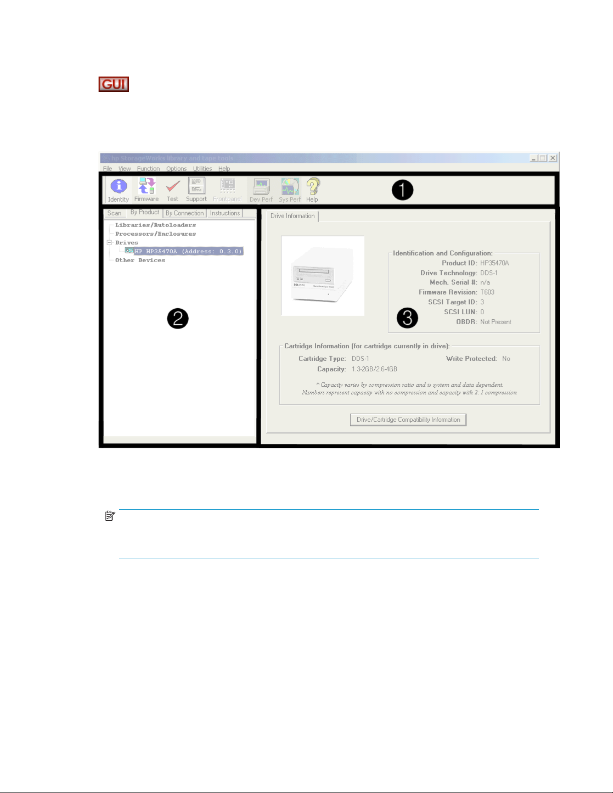
Figure 3 L&TT main screen
The three sections of the L&TT main screen are:
1. Taskb
2. Device List—This is a multi-function window that offers several options on the following tabs:
ar—This section contains but tons that provide quick access to the main functions of L&TT
and
to the online help system.
NOTE:
Above the Taskbar is the standard Windows menu bar that provides alternate navigation to tool
functions, as well as access to a number of other features.
• Scan—Provides either a summary status or detailed information (depending on whether
Show Details or Hide Details is
problem is encountered during the scan, this information m ay help in determining the
cause. When the scan completes successfully, the device list automatically switches to the
By
Product tab.
The Scan tab also lets you rescan the bus. If any devices have been hot-swapped or powered on
after the OS has booted, in most cases, the rescan feature can discover those devices without
requiring a reboot of the system.
selected) about the bus scanning process. If a
Library and Tape Tools User Guide
29
Page 30

CAUTION:
Swapping SCSI devices, including connecting and disconnectin g cables and/ or terminators, can
cause the system to hang or crash.
CAUTION:
On WindowsNT4.0,2000,XP, andWindows Server 2003, changingdevices at aspecific
SCSI address c a n cause unpredictable behavior. Parts of the operating system may not detect
that the device or device type has changed.
• By Product—Shows alistofall theproductsconnected to thesystem. The list isgrouped
into the following four categories:
• Libraries and autoloaders
•Drives
• Enclosures and processors
• Other devices
fields listed after the device represent the device address. Each field in the
The three num
address is separated by a period: the first field represents the HBA channel, the second field
represents the SCSI ID, and the third field represents the LUN.
NOTE:
When using the Miniport I/O mode, the HBA channel field is shown as “A/B,” where A is the
channel and
ber
is the subchannel.
B
• By Connection—Shows all products connected to the system, grouped by the HBA they
are connected to. This view makes it easy to see which devices are connected to the same bus
as the device in question, and may help in understanding system I/O performance issues.
• Instructions—Contains brief instructions on how to use the selected screen. This view
canbe disabledinthe software preferences.
3. Device Information screen—All the main functions of the program are displayed in this window.
The content of this window depends on the device and tool function selected.
Using the Device Information screen
When you select a product from the Device List, the Device Information screen displays information
relevant to the device. The Device List also changes to display instructions on this page ( if the instructions
preference is enabled). If another tool function is currently active, then clicking Identity on the toolbar
opens the Device Information screen.
The Device Information screen provides an overview of the selected hardware device and its current
configuration and status.
30
Getting Started with L&TT
Page 31

Standalone devi
TheDeviceInformation screen, showing astandalonedevice, contains asingletab
labeled Drive Information. The Device Information screen has four main sections.
ces
1.
A visual representation of the selected product (the images are in grayscale).
2.
Provides the following general information on the product:
• Product ID (Inquiry String)
• Drive Technology (DDS/DLT/SDLT/VS/LTO)
• Mech Serial # (Drive serial number)
• Firmware Revision
• SCSI Target ID
• SCSI LUN
3.
4.
a
If a dat
the
protect status is s hown here.
Click this button to display a list of media that is compatible with the product, as shown in
Figure 4. The information provided for each type of media is:
• Cartridge characteristics
• Capabilities of this drive to handle the cartridge
• HP part number for the cartridge
cartridge was inserted in the drive when the identity tool was selected (or when
current screen was refreshed), information regarding cartridge type, capacity, and write
Library and Tape Tools User Guide
31
Page 32
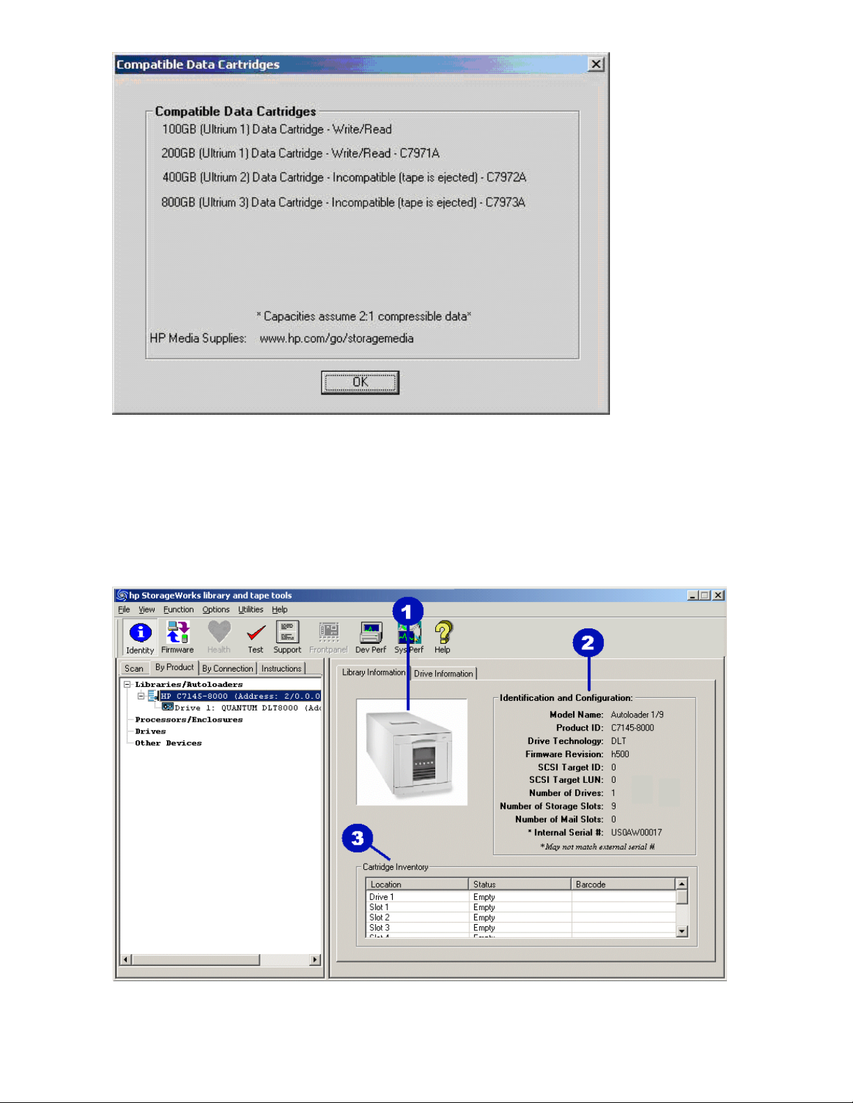
Figure 4 Compatib le data cartridges screen
Library and autoloader products
When a library or autoloader is selected in the Device List, the Device Information screen displays two
tabs: one for library information and one for the drives contained within the library.
Figure 5 Device Information screen showing a library
32
Getting Started with L&TT
Page 33

1.
A visual representation of the selected product (the images are in grayscale).
2.
As
with a standalone drive, this area provides the relevant information on the selected library
product.
3.
This provides a cartridge (media) inventory for all the drives and slots. The current status
(full or empty) of all the storage elements and the barcode number (if barcode reading is
available) is displayed here.
To see information for the drives within the library, select the Drive Information tab. This tab displays a
screen very similar to the one for standalone products, with the addition of the Selected Drive menu.
Because a libr
the
Selected
ary can contain multiple drives, you can select and view information for each drive using
Drive menu. All of the drives in the library are available in the menu.
NOTE:
Selecting individual drives within a library from the By Product/By Connection device list displays the
drive as though it were a standalone product. The recommended method of diagnosing embedded drives
is
to first select the library they belong to, and then select the specific drive within each tool window.
Library and Tape Tools User Guide
33
Page 34
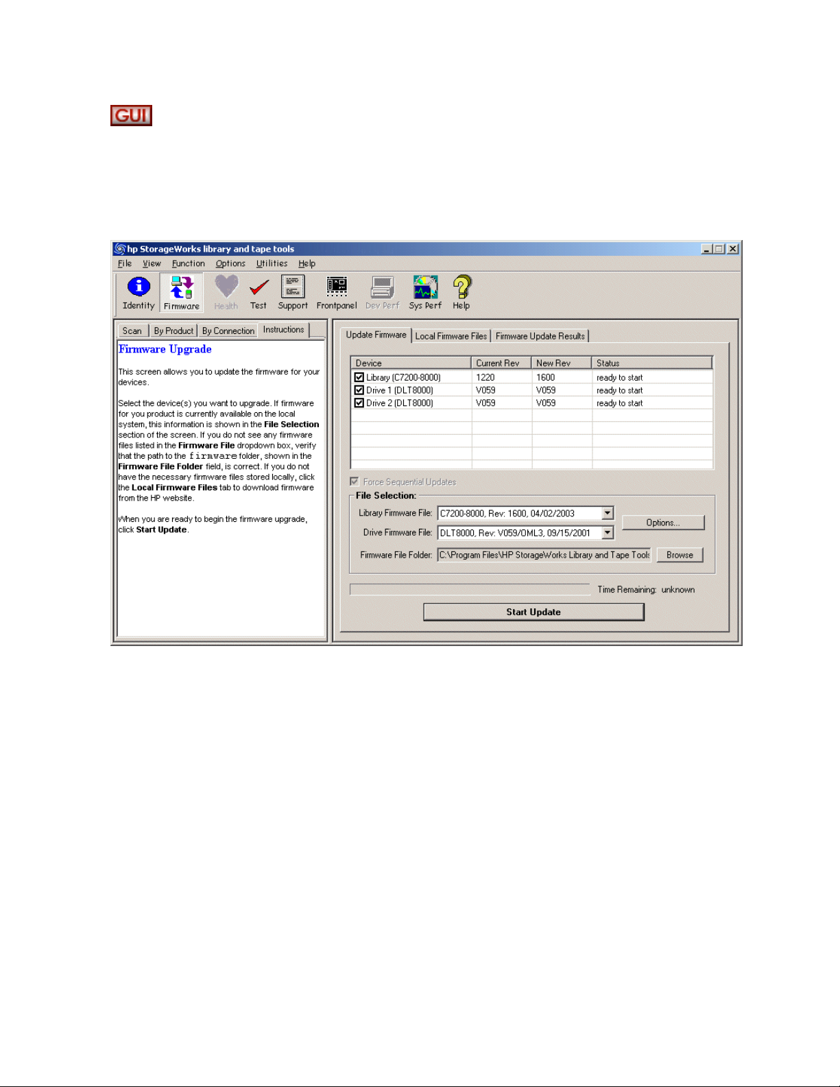
Using the Firmware Management screen
The firmware management functionality of L&TT allows easy upgrades to the storage product firmware. To
access the Fi
click the Firmware button on the main toolbar.
rmware Management screen, click the device you want to update in the device list, then
Figure 6 Firm
ware Management screen
For detailed information about the firmware management functionality of L&TT, see "Firmware
management" on page 43.
34
Getting Started with L&TT
Page 35
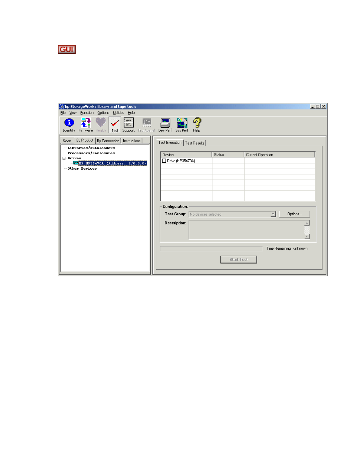
Using the Tests screen
L&TT provides several standard and advanced tests that can be used to check the performance of, or to
diagnose iss
the
device list, then click the Tests button on the main toolbar.
ues with, storage hardware. To access the Tests screen, click the device you want to test i n
Figure 7 Test
sscreen
For detailed information about the Tests screen, as well as information about how to perform the tests and
interpret test results, see "Tests and utility functions" on page 57.
Library and Tape Tools User Guide
35
Page 36
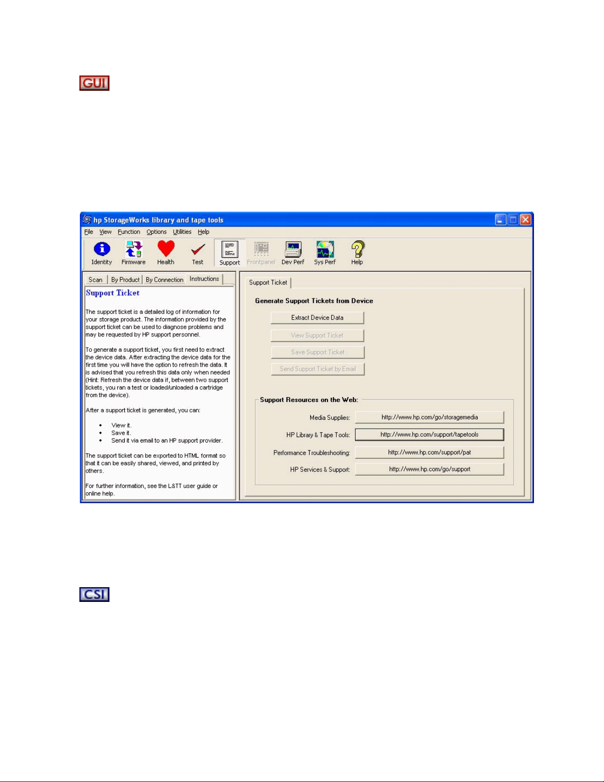
Using the Support Ticket Generation screen
L&TT can automatically generate a support ticket based on information that the program determines
about the system. The information in this support ticket can then be used to diagnose storage h ardware
can automatically e-mail the support ticket to the HP help desk to assist the help desk
issues. L&T
technician in resolving issues.
To access the Support Ticket Generation screen, click the device you want to generate the support ticket
for in the device list, and then click Support on the main toolbar.
Figure 8 Support Ticket Generation screen
T
tailed information about generating and using support tickets, see "Reports and support
For de
ets" on page 103. For specific information about the various options found on the Support screen,
tick
see "Using the Support screen" on page 104.
Starting L&TT (CSI)
To start L&TT:
• For HP-UX (pre-11 .31 ), Tru64, and Linux:
Log on as root and execute the following commands:
cd /opt/ltt
./hp_ltt
36
Getting Started with L&TT
Page 37

• For HP-UX 11.31:
HP-UX 11.31 provides a new address string format, which can be seen by executing ioscan -fN.
Start L&TT with the -N option to use the new address string format.
Log on as root and execute the following commands:
cd /opt/ltt
For the new address string format: ./hp_ltt -N
For the old address string format: ./hp_ltt
• For Novell NetWare
From the server console, execute the following command:
hp_ltt\hp_ltt
• For HP OpenVMS:
Run hp_ltt.exe found in the sys$sysdevice:[vms$common.opt.ltt] directory.
Library and Tape Tools User Guide
37
Page 38
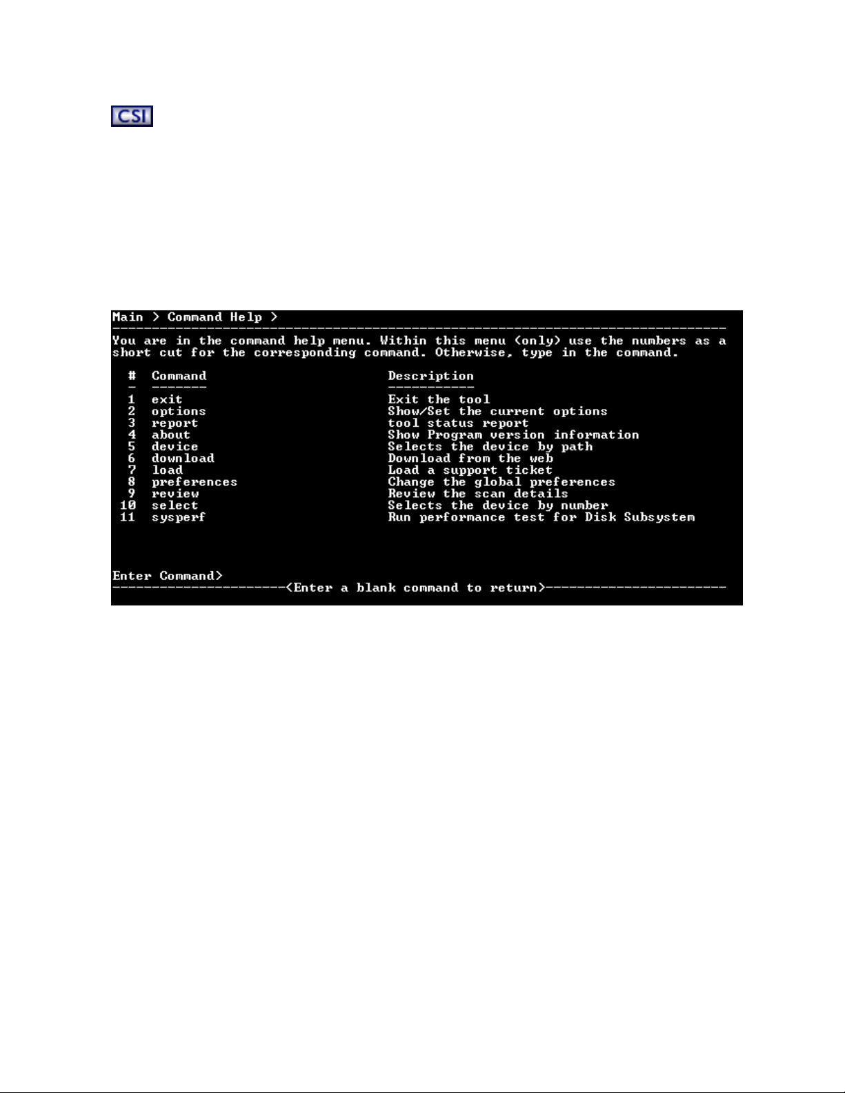
Navigating the screens
The top line of each screen displays the current screen name in hierarchical format. Each level of screens
is
separated
lower level in the hierarchy. To m ove back to the previous level, use the up command. To exit L&TT, use
the exit
On most of th
a
Command He
original screen from which the Command Help screen was accessed.
by the “>” character. On each screen, some of the available commands take you to a
command.
screens, entering a blank command (pressing Enter without typing any other text) displays
e
screen. This screen contains a l ist of valid commands that can b e executed on the
lp
Figure 9 Com
It is p ossible to enter a com m a nd directly from the Command Help screen. To do this, type either the
number of the command or the name of the command and press Enter. Entering the number of the
command
of the
command. To exit the Command Help screen, enter a blank command (press Enter).
mand Help screen accessed from the Main s c reen
only works on the Command Help screen. From any other screen, you must t ype the full name
Some commands require an argument. For example, the select command requires a number that
corresponds to the device you want to select in the device list. To select the firstdeviceinthe list, the
syntax is:
select 1
If you enter a command with an invalid or m issing argument, an error message is displayed.
38
Getting Started with L&TT
Page 39
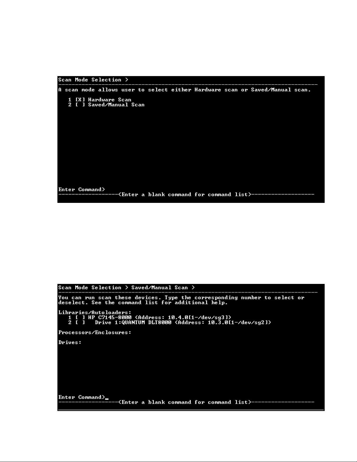
Using the Scan Mode Selection screen
When the CSI version of L&TT is started, the Scan Mode Selection screen opens.
Mode Selection screen
Figure 10 Sca
n
When L&TT starts, it performs a device scan to identify all the devices connected to the computer, either
directly or through a SAN. In large SAN environments, this scan can take a long time.
The first timeL&TTisrun,itmustperform afullhardwarescan(Hardware Scan option). After that
is done, the results of the scan are automatically saved so that the next time L&TT is started, the
Saved/Manual Scan
hardware scan is done, the list of available devices will be empty.
If you select Saved/Manual Scan, the Saved/Manual Scan screen opens.
Figure 11 Saved/Manual Scan screen (CSI)
option can be used. If the Saved/Manual Scan op tion is selected before a
Library and Tape Tools User Guide
39
Page 40
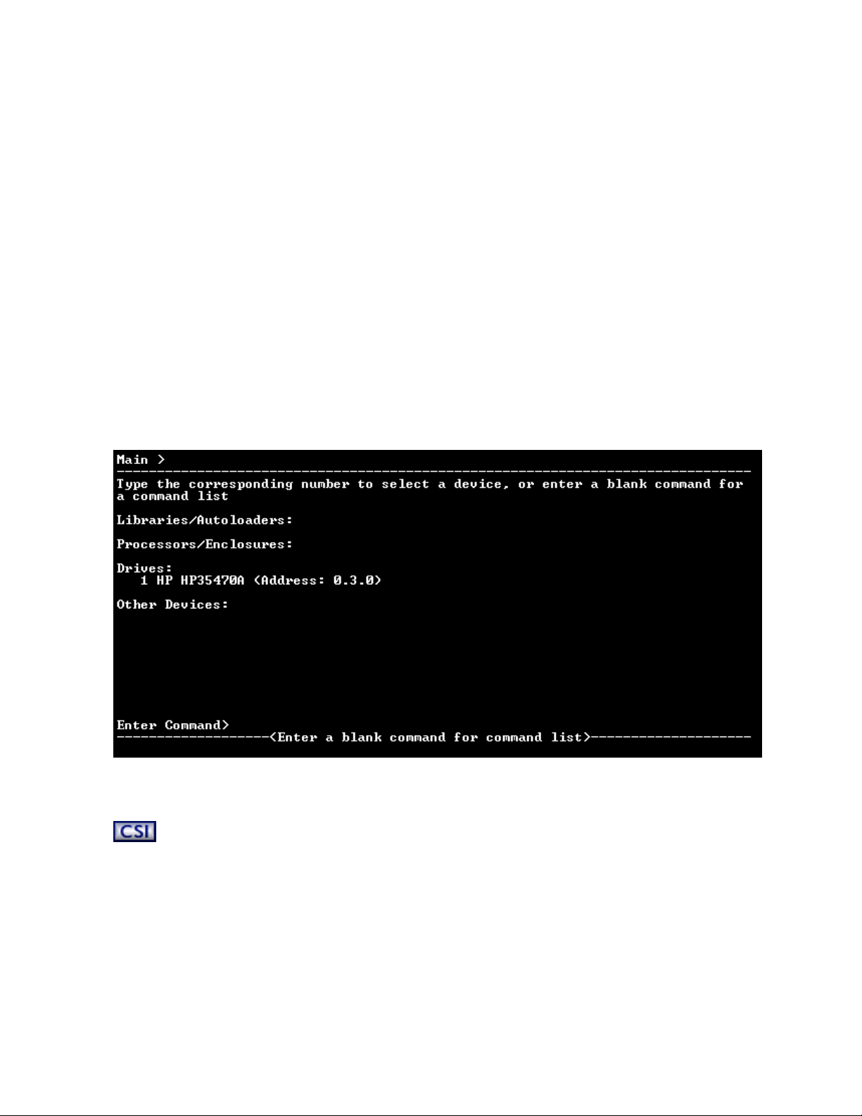
Using the Saved/
Manual Scan screen
Use the Saved/M
save time in a large SAN environment if you are using L&TT to test a single device. Any devices that are
not
selected will not be scanned, and they will not be displayed in the Device List on the L&TT Main screen.
The following c
• select—The indicated device or devices will be scanned.
• selectAll—All devices will be scanned.
• clear—The ind
• unselectAll—Clears all devices. No devices will be scanned.
• enterHWAddrManual—Manually enter the hardware address of a device to be scanned.
• hardwaresca
devices on the Saved/Manual Scan screen.
• continue—Starts the indicated scan and proceeds to the Main screen.
• up—Exits th
• exit—Exits L&TT.
When the scan is complete, the Main screen opens.
Figure 12 C SI Main screen
anual Scan screen to select the devices that you want L&TT to scan and identify. This can
ommand options are available:
icated device or devices will not be scanned.
n—Performs a full hardware scan. Use this op tion to update the list of available
current command level.
e
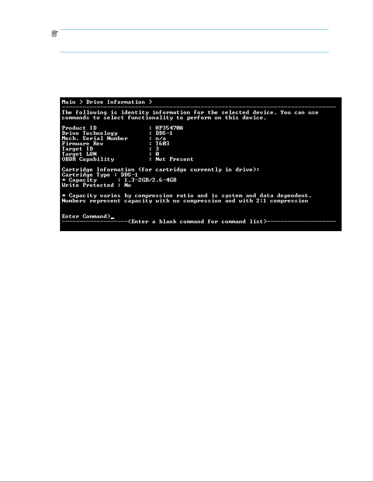
Using the Device Information screen
When you first select a product from the Main screen, the Device Information screen opens, showing
information relevant to the device.
Themainpurpose of theDeviceInformation screen is to provideanoverviewofthe configuration and
status of the selected hardware device.
From the Main screen, t ype the following command to access the Device Information screen:
select
40
<n> (where <n> is the number of the device to be examined)
Getting Started with L&TT
Page 41
NOTE:
Alternatively, you can omit the select command and enter only the device number.
Standalone devices
Figure13DeviceInformationscreenforastandalonedevice
The following general information is displayed:
• Product ID (inquiry string)
• Drive technology
• Mech. serial # (drive serial number)
• Firmware revision
• SCSI target ID
• SCSI LUN
• OBDR cap ability (if present)
If a data cartridge was inserted in the drive when the Device Information screen was displayed,
information regarding cartridge type, capacity, and write-protect status is shown.
To see a list of compatible media that can be used with this device, use the cartridge command.
Library and Tape Tools User Guide
41
Page 42

Library and a
Figure 14 Device Information screen for a library
utoloader products
NOTE:
Selecting individual drives within a library from the device list displays the drive as though it were a
standalone product. Embedded drives are best diagnosed by selecting the library they belong to, and
then selecting the specific drive within each tool window.
From the Device Information screen for a library device, use the cartridge command to display the
slot inventory of the library. The cartridge command shows which slots and drives currently have
cartridges loaded, and the cartridge barcode if available and applicable.
42
Getting Started with L&TT
Page 43

4 Firmware Man agement
The Firmware Management functionality of L&TT provides a convenient way to easily upgrade the
firmware of connected devices. Library firmware and firmware of drives within the libraries can be
upgraded as well.
L&TT uses special firmware files that associate the firmware with a particular product. This feature prevents
the
user from downloading the wrong ima ge and ensures that the downloaded firmware is the same as
or a
newer revision of the current device firmware.
CAUTION:
Do not use L&TT to update firmware on a tape library or devices within a tape library that is managed
with HP StorageWorks Command View for Tape Libraries Software (Command View TL). Firmware
update operations for these devices must be performed using Command View TL, as documented in the
HP StorageWorks Interface Manager and Command View for Tape Libraries Software user guide
L&TT is used to update firmware on a managed library, the management station will be out of sync with
the actual firmware revision number and will report a firmware mismatch. Furthermore, if you attempt to
use L&TT to update firmware on a partitioned library, L&TT reports an invalid command error.
Accessing firmware revision and release note information
(GUI)
.If
To verify that you have the latest firmware revision for a device, or to learn about the changes between
your current revision and the latest revision, use the Get Files from Web feature of L&TT.
To access firmware revision and release note information from the L&TT application (Windows):
1. In the L&TT main screen, click File > Get Files From Web,orclick the Firmware button on the menu
bar, select the Local Firmware Files tab, and then click Get Firmware From Web.The Get Files
From Web window o pens.
2. To view the latest firmware revisions for devices on your system, or for all devices, click the Firmware
tab, and then click the appropriate radio button.
3. To view release note information, click the product ID of the firmware file whose information you
want to view, and then click the Details button. If release notes are available, they are displayed
in the
File Details window.
To access firmware revision and release note information from the L&TT application (HP-UX and Linux):
NOTE:
The download function is not supported with NetWare, OpenVMS, or Tru64 UNIX.
1. On the L&TT main screen, enter download.
Arequired file from the HP FTP site is downloaded, and the Download Tool screen opens. The status
area at the bottom of the screen displays the progress of the download.
2. In the Download Tool area, enter 5 at the com m and prompt. The Selector screen displays the various
firmware files. Review the list and note the latest firmware revision for your product.
3. To review release note information, enter the num ber of the file whose release note information you
want to view. Use the ^U or ^D commands to page up or down through the screens to find the
desired product and firmware file. Not all firmware files have release note information available.
Library and Tape Tools User Guide
43
Page 44

Acquiring firmware files (GUI)
L&TT firmware files are stored in the Firmware directory. This directory is a subdirectory of the
HP Library &
acquire the firm
be obtained in three ways:
1. Select thedeviceinthe device listingand click Firmware on the main toolbar. On the Firmware
screen, click the Local Files tab, and then click the Get Files from Web button at the bottom of the
tab. The downl
2. From the L&TT menu, select Get Files From Web from the File menu. The software links to the
L&TT firmware FTP site and allows the selected firmware filestobecopiedtoyoursystem.
Downloaded fi
in
detail in the following section.
3. Go to h
and
standalone
libraries
firmware.
CAUTION:
Do not use the
so
can cause the system to lock up until it has timed out in the operating system. This timeout value
is
operating system-specific.
ttp://www.hp.com/support, choose the product family, then click software updates
drivers. The latest firmware file is available in L&TT format. For some products (such as
the firmware is available in a self-extracting bundle that includes library and drive
),
Get Files From Web
e Tools
Tap
ware image file or files and copy them to the Firmware directory. Firmware files can
oaded
les are automatically placed in the Firmware directory. This option is explained
drives), firmware is available as a single file. For other products (such as tape
installation directory. Before upgrading any firmware, you must first
files are automatically placed in the Firmware directory.
functionality within L&TT without an Internet connection. Doing
NOTE:
If Check for Updates on Web is enabled in the tool preferences, L&TT automatically informs the
user when new firmware is available for any of the connected storage products. L&TT performs this check
each time it is started (but not more than once per 24-hour period).
Using the Get Files from Web functionality (GUI)
The Windows version of L&TT offers comprehensive firmware management functionality that finds and
downloads firmware from the HP website. This functionality obtains the most up-to-date information
about al
the
Depending on the selected filter options on the top of the screen, different subsets of firmware files are
presented. Firmware files that are needed to bring the connected devices up to the latest firmware
revisions are automatically selected.
Accessing the Get Files from Web dialog box
You can access the Get Files from Web dialog box in two ways:
• Select Get Files from Web from the File menu
• Click the Get Firmware button on the Firmware Update screen
The Get Files from Web dialog box is displayed. Click the Firmware (New Files Available) tab if it is
not
lavailable firmware files directly from the HP website. It then compares this data set against
of devices connected to the system and the current firmware revisions present in those devices.
t
lis
already selected.
44 Firmware Management
Page 45

Figure 15 Get Files from Web dialog box—Firmware tab
Select
ing and downloading updated fi rmware files
The Get
• For devices on this system—These two options only show firmware files matching devices that are
• For all supported devices—These two options show firmware files for all devices supported by LTT,
Sele
the
directory on the local system. You can now use the firmware update functionality of L&TT to upload the
late
Files from Web dialog box has four filter options:
currently connected to the system.
• Show l
• Show all firmware shows all firmware revisions for each of these firmware files.
even i
• Show latest firmware only shows the most recent firmware revision for each device.
• Show all firmware shows all firmware revisions for each of these firmware files.
ct the appropriate option, and then verify that the correct firmware files are selected. To download
selected files, click Download.The files are automatically downloaded to the current firmware
firmware to your devices.
st
atest firmware only
not currently connected to the system.
f
shows the most recent firmware revision for each device.
Library and Tape Tools User Guide
45
Page 46

Viewing firmware revision history
In addition to downloading firmware files, the Get Files from Web dialog box provides revision history
detail for firmw are files. To view the firmware revision history of a device, select a device and click Details.
Uploading firmware to devices (GUI)
Before attempting to update any firmware files, you must firstacquire thelatest firmware files and ensure
that they are placed in the Firmware directory. If you have not yet done this, see Acquiring firmware
files (GUI).
To upload firmware to a device:
1. Click the device to update in the device list.
2. Click Firmware on the main toolbar.
3. On the Update Firmware tab, click the checkbox to select each device for which you want to
update firmware. If firmware is currently available for that device, it is shown in Firmware
File in the File Selection section of the screen.
Figure 16 Firmware Update screen
NOTE:
With several products, after the firmware file is selected, a message is displayed to inform you
of certainrequirementssuchasimportant prerequisitesfor updatingwiththe new firmware, or
noteworthy functional changes (such as a new LED sequence). Be sure to read any such messages
and take any appropriate actions.
4. Click the Start Update button at the bottom of the screen to begin the update.
46 Firmware Management
Page 47

CAUTION:
Make sure that no other programs attempt to access the device while the firmware is being updated.
Do not interrupt the firmware update. If the firmware update is interrupted, the device may not
operate and may require physical repair.
When the firmware update is complete, the Firmware Update window o pens, explaining what may
happen related to the Windows plug-and-play implementation. It also explains how to m ake the
drive visible to L&TT and the Windows operating system, so that it will operate properly.
If the device is not visible to L&TT and/or the operating system after you have s uccessfully updated
the
firmware, follow the process indicated in the Firmware Update window to ensure the updated
device is fully visible to and usable by the system. Make sure you follow this entire procedure
before calling HP customer support. If you have followed the procedure, and your device is still not
accessible, call HP customer support for assistance.
L&TT creates a log of all firmware update activity. To view this log, click the Firmware Update Results
tab. Set the Current Detail Level setting to the appropriate level. The default is Normal.If you
want to clear the log, click the Clear Log button.
Advanced options (GUI)
It is sometimes necessary to disable L&T T safeguards to perform more advanced operations. These
operations (options) are only available after you have entered the necessary password. To obtain this
password, contact HP support. After you have entered the password, the Options button on the Update
Firmware tab becomes available. When you click this button, the Factory Firmware Overrides dialog box
opens
(this dialog b ox varies slightly between drives and libraries):
Figure 17 Factory Firmware Overrides dialog box
Factory Firmware Overrides dialog box presents the following three options:
e
Th
• Allow firmware downgrading—By default, L&TT does not show files with older revision
levels as selectable. On the Local Firmware Files tab, the comment field displays the message
“downgrade password required.” In most cases, you should use the latest firmware. However, if
software incompatibilities or other customer limitations require the use of older firmware revisions,
his checkbox lets you downgrade to older firmware revisions.
t
• Allow selection of any [drive or library] firmware file—This option allows
mapping of the device firmware to a product, irrespective of the device’s product ID. There are a
few cases in which the product ID does not match the desired firmware file (and the ID may also
need
to be updated). One case is when a library is being updated from one drive technology
Library and Tape Tools User Guide
47
Page 48

to another. Another case is when the device has a firmware revision string format that differs
from that in the firmware file, and the tool cannot determine whether it is newer or older. If
incompatible firmware is sent to a device, an error message is displayed.
• Update [drive or library] product ID—This writes the product ID from the firmware
file to the drive.
NOTE:
A number of products may not support updating the product ID, so use this feature only when you
know the device supports it. The most common use of this feature is for updating drive technologies in
optical libraries.
Acquiring firmware files (CSI)
L&TT firmware files are stored in the firmware directory, which is a subdirectory of the HP Library &
Tape Tools
image
file or files and co py them to the firmware directory.
To download the latest firmware files:
installation directory. Before upgrading any firmware, you must first acquire the firmware
1. Go to h
category.
2. Select the product family, and then the particular product.
3. In the I would like to box, click downloaddrivers andsoftware.
4. Select the product and operating system, and then click the download button in the firmware
section. The download file may be a single file (standalone drives) or a self-extracting bundle
that
5. Download the file or files to the firmware directory. If it is a self-extracting bundle, extract the
contents to the firmware directory.
ttp://www.hp.com/support, choose your region, and then select storage for the product
includes both automation and standalone drive firmware.
Using the Get Files from Web functionality (CSI)
NOTE:
Downloading firmware files from the Web using the L&TT application is not supported with N etWare,
OpenVMS, or Tru64 UNIX.
The CSI
This functionality obtains the most up-to-date information about all available firmware files directly from
the
current firmware revisions present in those devices.
To use t
1. From the M ain screen, enter the download command. The Download Tool screen displays a
2. Enter
3. Enter the number of the desired firmware file to download. The file is downloaded to the
version (HP-UX and Linux) of L&TT can also find and download fi rmware from the HP website.
HP website. It then compares this data set against the list of devices connected to the system and the
he Get
list of download options.
displays a list of available firmware files to download.
firm
Files from Web functionality:
number of the desired option. If a download option is selected, the Selector screen
the
directory.
ware
48 Firmware Management
Page 49

Uploading firmware to devices (CSI)
To upload firmware to one or more devices:
1. From the Main screen, type the number corresponding to the device to be updated and press
Enter
to display the Device Information screen.
2. From the Dev
Update screen. Devices that are available for update are listed on this screen.
3. Type the corresponding number of the device you want to update and press Enter to mark
the
device selected. If there are multiple devices, repeat this step for each device that you
want to upd
4. When all the required devices are selected, enter the start command to begin the update
process.
CAUTION:
Make sure that no other programs attempt to access the device while the firmware is being updated. Do
not
interrupt the firmware update. If the firmware update is interrupted, the device may not operate and
may require physical repair.
L&TT creates a log of all firmware update activity. To view this log, enter the review command from
the
Firmware Update screen.
ice Information screen, enter the firmware command to display the Firmware
ate.
Advanced options (CSI)
Sometimes it is necessary to disable L&TT safeguards to perform more advanced o perations. These
operations (options) are only available after you enter the necessary password. To obtain this password,
contact HP support. To view the Options screen, from the Firmware Update screen, enter the options
command.
Before any of the op tions can be changed, the current password must be set. To set the password:
1. Type the number that corresponds to the password op tion and press Enter. L&TT p rompts you to
enter a value for Current password entered.
2. Type the password and press Enter. If the correct password is entered, the remaining options
on
this screen become available.
NOTE:
All of the options are visible regardless of whether a proper password is entered or not. However, the
options are not available for selection without the proper password. After a proper password has
been entered, it is not required to re-enter it later.
The following options are available:
• Allow firmware downgrading—By default, L&TT does not allow firmware downgrading. In
most cases, you should use the latest firmware. However, if software incompatibilities or other
omer limitations require the use of older firmware revisions, this option lets you downgrade
cust
firmware revisions.
lder
to
o
• Allow any firmware file for [drives or libraries]—This o ption allows
mapping of the device fi rmware to a product irrespective of the device’s product ID. There are a
few cases in which the product ID does not match the desired firmware file (and the ID may also
to be updated) : when a library is being updated from one drive technology to another;
d
nee
device has a firmware revision string format that differs from that in the firmware fi le,
en the
wh
Library and Tape Tools User Guide
49
Page 50

and the tool cannot determine whether it is newer or older. If incompatible firmware is sent
to a
device, an error message is displayed.
• Allow Product ID updates on [drives or libraries]—Thiswritesthe productID
from the firmware file to the drive.
• Current password entered—This option lets you enter the factory password. The currently
entered password is displayed to the right of the option. If no password has been entered,
Not Set is
NOTE:
A number of products may not support updating the product ID, so use this feature only when you know
thedevicesupportsit. The mostcommonuse of this featureiswhen updatingdrive technologies in
optical libraries.
displayed.
Using a firmware update (FUP) tape
The preferred method for updating drive firmware is by using the L&TT application. Firmware can be
updated on both Windows and non-Windows platforms. However, there are some cases where L&TT
is not
available, or otherwise cannot be used (for example, with an unsupported operating system). In
these cases, a firmware update (FUP) tape can be created and used for the purpose of updating drive
firmware. In most cases, FUP tapes can be created by HP and supplied to end users, or be created
by the end users themselves.
When using L&TT to update firmware, there are protections in place to ensure that only the correct
firmware is downloaded to the drive. There is no such protection mechanism with a FUP tape, so care
must be taken to use the FUP tape only with the drive it is intended for.
Performing the update
The procedure for using a FUP tape varies depending on the drive type, and in some cases, whether
or
not the drive is in an autoloader or library. Click the appropriate drive type below to get the details
associated with using a FUP tape for that drive.
•SDLT
• DLT VS80/DLT1
• DLT 4000/7000/8000
•Ultrium
•HP DDS/DAT
• Compaq/Sony AIT & DDS
SDLT
Standalone SDLT drives
There is no hard-coded limit on the number of times a given SDLT FUP tape can be used to update the
firmware in a particular SD LT drive type. To update the firmware in an SDLT drive using a FUP tape,
you firsthavetoput thedrive in FUP tape mode.
To put the drive in FUP tape mode:
1. Unload any tape currently in the SDLT drive.
2. With no tape in the drive, push and hold the eject button. After approximately five seconds, the left
LED
begins to flash.
3. Release the eject button, and then push it again. The middle LED will also start flashing.
4. Releasethe ejectbutton. Thedriveisnow readytoaccept the FUPtape.
50
Firmware Management
Page 51

5. Insert the FUP tape into the drive. It does not matter if the tape is write protected or write enabled.
CAUTION:
Do not power cycle or reset the drive. Make sure that no software attempts to access the
drive during the firmware update process. Otherwise the drive may be damaged and
need to be returned to HP for replacement.
NOTE:
If thedrive is notput into FUPtape mode beforeyou insert theFUP tape,it willnot be
recognized as a FUP tape. If the FUP tape is not write protected, you will be able to write
over the FUP tape (but not append to it).
6. When the firmwa
7. Store, return, or dispose of the FUP tape as required. To convert the FUP back into a data tape, see
"Converting a firmware update tape to a data tape" on page 55.
Libraries and autoloaders
Use of FUP tapes in STK libraries works just like it does for standalone drives. See the description above
for that information.
For HP libraries:
1. Ensure the target drive is empt y. If a tape is in the target drive, use the front panel display to return
the tape to a storage slot.
2. Load the FUP tape into an empty slot.
3. From the main menu on the front panel, choose Administration, and then Upgrade Firmware to
access the Upgrade Drive Firmware menu.
4. Use the [-]or[+] key to select the slot containing the FUP tape. Select [OK].
5. Monitor the front panel for status during the upgrade. The tape will return to the original slot when
the procedure is complete.
6. Remove the FUP tape from the library, and then power cycle the library.
DLT VS80/DLT1
Standalone VS80/DLT1 drives
There is no hard-coded limit on the number of times a given DLT VS80/DLT1 FUP tape can be used
to update the firmware in a par ticular DLT VS80/DLT1 drive type. To update the firmware in a DLT
VS80/DLT1 drive using a FUP tape, you firsthavetoput thedriveinFUP tape mode.
To put the drive in FUP tape mode:
1. Unload any tape currently in the DLT VS80/DLT1 drive.
re update process is complete, the drive ejects the FUP tape and performs a self test.
2. With no tape in the drive, push and hold the eject button. After approximately five seconds, the left
and
right LEDs light.
3. Continue to hold the eject button depressed until all the LEDs go out.
4. Immediately release the eject button. The middle LED will light.
5. Push and release the eject but ton. All LEDs will start flashing. The drive is now ready to accept the
FUP
tape.
6. Insert the FUP tape into the drive. It d oes not matter if the tape is write protected or write enabled.
Library and Tape Tools User Guide
51
Page 52

CAUTION:
Do notpower cycleorreset the drive. Makesurethatnosoftwareattemptstoaccessthe
drive during the firmware update process. Otherwise the drive may be damaged and
need to be returned to HP for replacement.
NOTE:
If thedrive is notput into FUPtapemodebeforeyou insert the FUP tape,itwillnot be
recognized as a FUP tape. If the FUP tape is not write protected, you will be able to write
over the FUP tape (but not append to it).
7. When the firmware update process is complete, the drive ejects the FUP tape and performs a self test.
8. Store, return
"Converting a firmware update tape to a data tape"onpage55.
Libraries and autoloaders
Use of FUP tapes in STK libraries works just like it does for standalone drives. See the description above
for that information.
For HP libraries:
1. Make sure that the target drive is empty. If a tape is in the target drive, use the front panel display
to
return the tape to a storage slot.
2. Load the FUP tape into an empty slot.
3. From the main menu on the front panel, choose Administration, and then Upgrade Firmware to
access the Upgrade Drive Firmware menu.
4. Use the [-]or[+] key to select the slot containing the FUP tape. Select [OK].
or dispose of the FUP tape as required. To convert the FUP back into a data tape, see
,
5. Monitor the front panel for status during the upgrade. The tape will return to the original slot when
the procedure is complete.
6. Remove the FUP tape from the library, and then p ower cycle the library.
DLT 4000/
Standalone VS80/DLT1 drives
7000/8000
There is no hard-coded limit on the number of times a given DLT 4000/7000/8000 FUP tape can be
used to update the firmware in a particular DLT 4000/7000/8000 drive type. To update the firmware in
a
DLT 4000/7000/8000 drive using a FUP tape, you first havetoput thedrive in FUPtapemode.
To put the drive in FUP tape mode:
1. Unload any tape currently in the DLT 4000/7000/8000 drive, and then lower the operator handle.
2. With no tape in the drive, push and hold the unload button. After approximately five seconds,
the Write Protect LED begins to flash.
3. Release the unload button and immediately press it again. The Tape In Use LED will now also flash.
4. Release the unload button. The drive is now ready to accept the FUP tape.
5. Lift the operator handle, insert the FUP tape into the drive, and then lower the operator handle. It
does not matter if the tape is write protected or write enabled.
52
Firmware Management
Page 53

CAUTION:
Do not power cycle or reset the drive. Make sure that no software attempts to access the
drive during the firmware update process. Otherwise the drive may be damaged and
need to be returned to HP for replacement.
NOTE:
If thedrive is notput into FUPtape mode beforeyou insert theFUP tape,it willnot be
recognized as a FUP tape. If the FUP tape is not write protected, you will be able to write
over the FUP tape (but not append to it).
6. When the firmware update process is complete, the drive ejects the FUP tape and per forms a self
test. Lift the
7. Store, return, or dispose of the FUP tape as required. To convert the FUP back into a data tape, see
"Converting a firmware update tape to a data tape" on page 55.
Libraries and autoloaders
Use of FUP tapes in STK libraries works just like it does for standalone drives. See the description above
for that information.
For HP libraries:
1. Make sure that the target drive is empt y. If a tape is in the target drive, use the front panel display
to return the tape to a storage slot.
2. Load the FUP tape into an empty slot.
operator handle and remove the FUP tape.
3. From the main menu on the front panel, choose Administration, and then Upgrade Firmware to
access the Upgrade Drive Firmware menu.
4. Use the [-]or[+] key to select the slot containing the FUP tape. Select [OK].
5. Monitor the front panel for status during the upgrade. The tape will return to the original slot when
the procedure is complete.
6. Remove the FUP tape from the library, and then power cycle the library.
Ultrium
Standalone Ultrium drives
There is no hard-coded limit on the number of times a given Ultrium FUP tape can be used to update the
firmware in a par ticular Ultrium drive type. To update an Ultrium drive with a F UP tape, insert the tape
into the Ultrium drive. It does not matter if the tape is write protected or write enabled. HP Ultrium drives
automatically recognize a valid FUP tape when inserted and begin updating the firmware. When the
firmware update process has completed, the tape is ejected, and the drive executes a self test.
CAUTION:
Do not power cycle or reset the drive. Make sure that no software attempts to access the drive during
the firmware update process. Other wise the drive may be damaged and need to be returned to HP
for replacement.
NOTE:
Ultrium FUP tapes can be converted back to data tapes via the LTO Firmware to Data Tape Creator
test. See that test description for details.
Library and Tape Tools User Guide
53
Page 54

Libraries and a
Use of FUP tapes in STK libraries works just like it does for standalone drives. See the description above
for that information.
For HP librarie
1. Make sure that the target drive is empty. If a tape is in the target drive, use the front panel display
2. Load the FUP ta
3. From the main menu on the front panel, choose Administration, and then Upgrade Firmware to
4. Use the [-]or
utoloaders
s:
to
return the tape to a storage slot.
into an empty slot.
pe
access the Upgrade Drive Firmware menu.
[+] key to select the slot containing the FUP tape. Select [OK].
5. Monitor the f
the procedure is complete.
6. Remove the FUP tape from the library, and then p ower cycle the library.
HP DDS/DAT
Standalone DDS/DAT drives
that are created using the firmware tape creator test can be used 1000 times. Drives that
DDS FUP tape
can
be updated via an FUP tape are HP DDS4 (C 5683A) and HP DAT72 (C7438A). Updating drive
firmware via F UP tape is not supported on other HP DDS/DAT drives.
To update DDS/DAT drive firmware with a FUP tape, ensure that the tape is write enabled, and then
insert it i
inserted,
tape is
CAUTION:
Do not power cycle or reset the drive. Make sure that no software attempts to access the drive during
the firmware update process. Otherwise the drive may be damaged and need to be returned to HP
for replacement.
NOTE:
DDS/DAT FUP tapes cannot be converted back to data tapes. After a FUP tape is created, it can only be
used as a FUP tape and cannot be written to again.
s
nto the DDS/DAT drive. HP DDS/DAT drives automatically recognize a valid FUP tape when
begin updating the fi rmware. When the firmware update process has completed, the
and
ected, and the drive executes a self test.
ej
ront panel for status during the upgrade. The tape will return to the original slot when
Libraries and autoloaders, other than DAT72x10
DDS/DAT autoloaders using a FUP tape is not currently supported, except for the DAT72x10
Updatin
autoloader.
DAT72x10 autoloader
The FUP tape will update both the autoloader and drive firmware.
To create a FUP tape for a DAT72x10 autoloader:
1. Place the drive firmware and autoloader fi rmware files in the firmware folder.
2. Rename the drive firmware file firmware1.frm.
3. Rename the autoloader firmware file firmware2.frm.
54 Firmware Management
g
Page 55

4. In L&TT, select the autoloader (not the drive) and choose the DAT AL Firmware Tape Creator test.
To upgrade firmware using the FUP tape:
1. Move the FUP tape to a slot in the autoloader.
2. On the autoloader front panel, select FW Update U sing Cartridge from the Support menu. The
autoloader front panel will display the status during the firmware update process and will indicate
when the update has completed
Compaq/Sony AIT & DDS
Standalone DDS/DAT drives
There is no hard-coded limit on the number of times a given Compaq/Sony AIT/DDS FUP tape can
be
used to update the firmware in a particular drive type. To update AIT/DDS drive firmware with a
FUP
tape, ensure that the tape is write protected, and then insert it into the AIT/DDS drive. The drive
automatically recognizes a valid FUP tape when inserted, a nd begins updating the firmware. When the
firmware update process has completed, the tape is ejected, and the drive executes a self test.
CAUTION:
Do not power cycle or reset the drive. Make sure that no software attempts to access the drive during
the firmware update process. Other wise the drive may be damaged and need to be returned to HP
for replacement.
NOTE:
DDS/DAT FUP tapes cannot be converted back to data tapes. After a FUP tape is created, it can only be
used as a FUP tape and cannot be written to again.
Libraries and autoloaders
The process for updating drive/autoloader firmware via FUP tape is the same as documented above for
standalone AIT/DDS drives.
Converting a firmware update tape to a data tape
In many cases, FUP tapes can be converted back to a regular data tape. The method of doing this
varies de
• DLT 4K/7K/8K, SDLT, and VS80/DLT1 tapes can be converted back to data tapes by making
• LTO driv
• HP StorageWorks and Surestore DDS, A IT, and Compaq/Sony DDS drives cannot convert FUP
pending
sure they are write-enabled, inserting them into a drive, and then writing to them.
back to a data tape.
tapes b
ack to data tapes.
on the drive type.
require the"LTO Firmware to Data Tape Creator" on page 77 to convert a FUP tape
es
Library and Tape Tools User Guide
55
Page 56

56
Firmware Management
Page 57

5 Tests and utility functions
L&TT provides numerous tests for analyzing storage h ardware. These tests are g rouped into two
categories: diagnostic tests and performance tests. The performance tests are built into the p rogram, but
several of the diagnostic tests are SCSI script-based. A SCSI script is a sequence of SCSI commands
sent to a device, usually for the purpose of testing the device’s functionality. SCSI scripts can also b e
used to perform non-diagnostic utility functions, such as rewinding a tape, recalibrating a tape he ad, or
exercising a tape-moving robot arm.
L&TT uses the following types of SCSI scripts:
• Script-based tests are tests based on scripts that are stored in the scripts d irectory in the L&TT
installation directory. The script-based test files can have the *.tst, *.plg, *.pmg *.smd,
or *.rul
• SCSI utility scripts provide access to generic SCSI operations. These scripts are accessed by
selecting Run Script... from the Utilities menu and have the *.scc or *.cps extension. For
more information, see Using the utility functions.
NOTE:
Each script file contains information that tells L&TT which devices it is designed to support. When a
device is selected, the Tests screen displays only tests that are applicable to that particular device.
extension.
NOTE:
All scripts have a digital signature and cannot be altered. If they are altered in a text editor, L&TT
displays an error message stating that the digital signature is not correct.
Library and Tape Tools User Guide
57
Page 58

Running the tests (GUI)
To select and run a test manually:
listing (the By Product or By Connection tab),click thedevicetotest.
1. In the devic
2. Click Test on the main toolbar. The Tests screen opens with the Test Execution tab selected.
3. Click the checkbox to the left of the device name that you want to test. The Test Group menu lists
all the test
4. In the Test Group menu, select the test to perform. The Description text box describes the
selected test.
5. If any opti
button to review and set the desired options.
6. Click the Start Test button to start the test.
e
available for the selected device.
s
are available for the selected test, the Options button is enabled. Click the Options
ons
Viewing test results
After the test has completed, click the Test Results tab to view the results. The Test text box shows the
results of the test. A more detailed Test Operation Log is displayed in the bottom section of the screen.
Click the “+” or “–” signs to expand or collapse a section of the report. Select an option in Current Detail
Level to display more or less information in the Test Operation Log.
Running the tests (CSI)
To select and run a test manually:
screen, enter the number corresponding to the device that you want to test. The
1. On the M
Device
2. On the Device Information screen, enter the test command. The Test screen displays the
currently selected test and lists the available devices to be tested.
3. To sel
number of the test you want to perform. The Test screen opens again and updates the currently
selected test.
4. To se
sele
5. Enter the start command to start the test.
6. When the test is complete, a dialog shows preliminary results of the test. Press any key to
urn to the Test screen.
ret
ain
Information screen opens.
ect a different test, enter the picktest command. On the Selector screen, enter the
lect or deselect devices to be tested, enter the corresponding device number to toggle the
cted status of the device. To deselect all devices, enter the clear command.
Viewing test results (CSI)
To view detailed test results, enter the review command. Test results are displayed in a hierarchical
format.
Use the detail comma nd without any arguments to view the current detail level of the report. Use the
detail
are as follows:
• 1—highlights only
• 2—normal
• 3—more details
• 4 — everything
• 5 — factory only (requires a factory password. To enter a password, use the options command.)
If necessary, use Ctrl+U and Ctrl+D to scroll up and down through the results. Use the find and page
commands
58
command with a numeric argument to set the detail level. The available detail level arguments
to quickly locate information in the report.
Tests and utility functions
Page 59

Test descriptions
L&TT provides two types of tests:
•Performance te
• Diagnostic tests
CAUTION:
Some tests are destructive to data on the media. When a test is destructive to data, this is indicated in the
test descript
can be erased. Do not attempt to perform a test unless you are thoroughly familiar with its usage, or
have been instructed to do so by HP support personnel.
Performance tests
• Drive Performance Test writes data to a tape drive and calculates the performance of that drive
independently from the disk file system. Use this test in conjunction with the System Performance
Test to identify any system bottlenecks. Use a blank tape when per forming this test because this
test is destructive to data on the tape. The test can also measure tape drive read performance.
This test is available for all tape drives. For more i nformation, see "Using the Drive Performance
test" on page 88.
• System P erformance Test has two modes: The backup pre-test measu res the read performance of
the
of
Performance Test to identify any system bottlenecks. The backup pre-test is read-only and is safe to
run on any part of your file system. The restore pre-test creates data in the specified directory
and
"Using the System Performance test"onpage92.
ion. To prevent data loss, use media that is either new or that contains unimportant data that
disk file system (simulating a backup), and the restore pre-test measures the write performance
the disk file system (simulating a restore). Use these tests in conjunction with the Drive
can also be used to create test data for general backup testing. For more information, see
sts
Diagnostic tests
NOTE:
L&TT tests are constantly updated to improve test coverage and problem diagnosis. As new device issues
are discovered, changes are made to the tests to properly diagnose those issues. Test script updates are
distributed with updates to L&TT or with a hot fix distribution. To ensure that you have the latest available
test scripts, keep your version of L&TT up to date, and download updates and hot fixes when they are
made
available from http://www.hp.com/support/TapeTools.
Library and Tape Tools User Guide
59
Page 60

NOTE:
The tests in this section are listed alphabetically. Click the hyperlink to view the test description.
Acceptance test
Assessment test
Autoloader Exerciser test L TO Cooling Check test
Compare Statis
Connectivity test
DAT autoloader firmware tape creator
Data Compression test
Device Analysis test Media Erase test
Device Configuration test
Device Self-Test
DLT SRAM Check test (short and long versions)
ESL Vendor ID test
Firmware Tape Creator (FUP tape)
ForceTape Ejectutility
Full Sweep test Read Media IDs test
Initialize
Acceptance test
Beginning with L&TT v3.5 SR1, the Acceptance tests have been replaced with the "Assessment
tests" on page 60. If you are using any diagnostic tools or documentation that recommend running the
Acceptance test, run the Assessment test instead.
Assessment test
tics test
Element Status test
Installation Check test
Library Exercisor test
LTO Firmware to
L TO Media Assessment test
LTO Stuck Tape test
Media Analysis test
Media Validation test
MO Media Validation test
Move test
Read/Write Stress test
Read/Write test
RestoreFactory DefaultSettings
SDLT Tape Ed
Data Tape Creator
ge Damage
(TED) test
CAUTION:
This test is destructive and will overwrite data on the media that is present in your product.
Description
NOTE:
For instructions on how to perform this test, see "Running the tests
(GUI)" o
tests (CLF)"on page 123.
NOTE:
In versions of L&TT prior to 3.5 SR1, this test was called the Device
Acceptance test.
NOTE:
In the L&TT test menu, the Assessment test may be prefixed with the device
type. For example: SDLT Assessment test.
The Assessment test determines if the drive or autoloader is Fit for Purpose
(FFP). A device that is determined to be FFP performs according to its
specification. If a device fails the Assessment test, it should be replaced. If
it passes, the problem is likely not with the health of that device. If a device
n page 58, "Running the tests (CSI)"onpage58 or"Running
60
Tests and utility functions
Page 61

is returned, the results of this test are c ompared to repair data to ensure
accuracy and enable test improvements to be d eveloped.
NOTE:
If thetestis being runonan autoloader and it is configured in
or
stacker
unload
mode (dependent on the par ticular autoloader), when an
commandisreceivedfrom the host (suchasisissuedwiththe
circular
Assessment test), the autoloader moves the next available cartridge into
the drive. If the magazine is not loaded with data cartridges and cleaning
cartridges in the correct order to meet the needs of the test, the test will
fail. HP recommends using the single cartridge process when running the
Assessment test on an autoloader.
DLT, DLT1, VS80, VS160, and SDLT Assessment tests performed:
• SCSI interconnect test
• Review event log entries (that were present prior to running this test)
• Load the test tape
• Quick write/read test
• Soft unload/load test (DLT assessment test only)
•Minimum block size test
• Diagnostic self test (built-in drive function)
• Read/write tests, using various data patterns
• Bit error rate test
• Review new event log entries added during the test
• Unload the test tape
LTO Assessment tests performed:
• Initial preparation
• Review event log entries (that were present prior to running this test)
• SCSI parity check (LTO 1 drives only)
• Cartridge load
• Quick read/write test
• Cartridge unload
•SCSI parity check
• Review new events
DDS A ssessm ent tests performed:
• Review event log entries (that were present prior to running this test)
• Check life data in the serial EEPROM and the fault log
•Load check
• Perform aclean andwrite test
• Unload check
•MRS switch test
•Read check
• Review new events
1/8 Auto loa d e r Assessment tests performed:
• Review robotics error log entries
• Run appropriate drive assessment test on the drive
• Check for new robotics error log entries
Library and Tape Tools User Guide
61
Page 62

• Perform 12 to 24 drive loads and unloads (depending on drive type)
• Check for new robotics error lo g entries
Options SDLT,LTO,and DDS Assessment test options:
The SDLT, LTO, and DDS assessment tests each have a test option Allow
Overwrite, which defaults to False and can be set to True to run the test
without a warning message about overwriting data. This option allows the
assessment tests to run through the c ommand line. In the command line, the
Allow Overwrite
option must be set to True for the test to run. Additional
options are available for the LTO Assessment test.
LTO Assessment test options:
For the LTO test, the following four options are available:
• Enable Device Analysis: True by default
• Enable SCSI Controller Test: True by default
• Enable Write/Read Test: True by default
• Ignore Cleaning Requests: False by default
When to run Run this test if you suspect a drive has failed. You should run the Media
Test option if you are running an SDLT 220 drive and you suspect the
drive may be damaging media, or if directed to do so by an HP tool or
support person.
Average dura- Test times vary g reatly depending on drive type, media qualit y, and options
tion
selected. Average time for a healthy drive with good tape can range from
10 to 20 minutes. A marginal drive (or drive with marginal tape) may
take substantially longer. Average duration for the SDLT Assessment test
with the Media Test option enabled is 20 minutes, but it can take l onger
with a bad tape.
Other notes Requires a good tape that will be overwritten as part of test.
Available for • DLT 4000/7000/8000
•DLT1/VS80/VS160
• SDLT 220/320/600
• LTO1 (Ultrium 215 and 230), LTO 2 (Ultrium 448 and 460) drives, and
LT O3 drives (Ultrium 920 and 960)
• DDS3, DDS4, and DAT72 (pre- and post-merger HP drives only)
• 1/8 Autoloader
62
Tests and utility functions
Page 63

Autoloader Ex
Description Checks the mechanics of your DDS autoloader.
When to run Run this test when you want to verify that the me chanics of your DDS
Average dura- ~10minutes
tion
Other notes Test will not overwrite any data on the media.
Available for DDS autoloaders
erciser test
NOTE:
For instructions on how to perform this test, see "Running the tests
(GUI)"on pag
autoloader are working properly.
e58 or"Running the tests (CSI)" on page 58.
Library and Tape Tools User Guide
63
Page 64

Compare Stati
Description This test reads current statistical values from the library (number of moves
When to run This test is most useful when used in conjunction with other tests by running
Average dura- Since no library motion is necessary, this test completes in just a few
tion seconds.
stics test
and retries, for example) and compares the current values to values saved
this library by this same test. It can be useful to run this test
previously
before and after running another L&TT test that exercises the library to see if
there are changes in key statistics that would indicate a problem. If the test
has never been executed before on the library, there will be no results to
make a comparison with, but the current statistical values will be displayed
and
on the lib
one to four executions of the test.
NOTE:
For instructions on how to perform this test, see "Running the tests
(GUI)"on page58or"Running the tests (CSI)" on page 58.
this test before and after running a test that exercises the library. Statistics,
such as move retries, can then be compared to determine if the library is
running without error.
in
comparisons when the test is run in the future. De pending
saved f
or
rary type, results can b e saved in the library for anywhere from
Other notes None.
Available for This test is available for MSL 2024, MSL 4048, ESL E-Series, EML libraries,
and
the 1/8 G2 Tape Autoloader.
64
Tests and utility functions
Page 65

Connectivity
Description Writes data to the internal buffers in your product to verify that the physical
test
connection between your host and the storage device is operational. No
media is req
NOTE:
For instruc
(GUI)"on page 58or"Running the tests (CSI)" on page 58.
uired.
tions on how to perform this test, see "Running the tests
Command line
syntax
The Connectivity test is available from the command line. For more
information, see "Running tests (CLF)" on page 123.
Test name: Connectivity Test
Options:
• Looping Options—Specify Count based loop or Time based
loop(min). In either case, the actual value is entered separately using
the Looping value
Forexample,toset atime-basedloopof10minutes:
testopt=”Looping Options:Time based loop(min)”
testopt=”Looping value:10”
• Looping value—Specify an i nteger greater than zero.
For example, to set a count-based loop to iterate five times:
testopt=”Looping Options:Count based loop”
testopt=”Looping value:5”
NOTE:
If no options are specified, by default L&TT runs the test with looping
options set to Count based loop with a looping value of 1.
parameter.
When to run Run this test when there is a question about the integrity of the bus
connection from the device to the host computer.
Average dura- <1 minute
tion
Other notes Test will not overwrite any data on media p resent in the drive.
Available for AIT, D DS, DLT, LTO, VS 80/VS160, MO, STK 9840 drives, and MSL libraries
Library and Tape Tools User Guide
65
Page 66

DAT autoloader firmware tape creator
Description Lets you create a firmware update (FUP) tape for your DAT72x10 autoloader,
using the DA
when a firmwa
NOTE:
For instruc
(GUI)"on page58or"Running the tests (CSI)" on page 58.
When to run Run this test when you want to create a firmware update (FUP) tape to
update firmware for a DAT72x10 autoloader.
Average dura- < 2 minutes
tion
Other notes This utility expects to find two firmware image files in your firmware
directory. The drive firmware file shou ld be named firmware1.frm and
the
autoloader firmware image file should be named firmware2.frm .
You m ust create these files yourself by obtaining the correct firmware files
foryourDAT72x10autoloader, renaming the files to firmware1.frm and
firmware2.frm, and copying the files to your firmware directory.
Available for DAT72x10 autoloader
T72x10 to create the tape. A FUP tape is a tape that is created
file for a particular drive type is written onto a blank tape.
re
tions on how to perform this test, see "Running the tests
66
Tests and utility functions
Page 67

Data Compress
CAUTION:
This test is destructive and will overwrite data on the media that is present in your product.
Description Tests thehardwarecompressioncapabilityofyourtapedrive. Thetest
When to run Run this test when you want to verify that data compression is working
Average dura- <10minutes
tion
ion test
writes a da ta pattern of known compressibility to tape. The test then
rewinds the tape and reads the file just written. The read and write
hardware compression ratios are calculated to ascertain that the hardware
compression is enabled and working. The compression ratios are displayed
and
should be approximately 2:1. This test is useful if tape capacity or
hardware compression is in doubt.
NOTE:
For instructions on how to perform this test, see "Running the tests
(GUI)"on page 58or"Running the tests (CSI)" on page 58.
properly.
Other notes Test will overwrite all data on the media.
Availablefor Alltapeproducts(driveand automation)supported by L&TT
Library and Tape Tools User Guide
67
Page 68

Device Analys
Description The Device Analysis test runs a device-specificscriptthatcarries outa
Command line The Device Analysis test is available from the command line. For more
syntax information, see "Running tests (CLF)" on page 123.
When to run Run this test when you want to verify that basic functions of the device are
is test
detailed examination of the device. The test examines all available logs
from the device to look for any known issues, customer use issues, and
patterns. The test also provides summary information and
common erro
presents suggestions as to the cause of certain errors and any remedial
actions the user should take. This option is particularly useful if you suspect
that there may be a problem with the device. For more information, see
"Using the
NOTE:
For instru
(GUI)"on page58or"Running the tests (CSI)" on page 58.
Test name: Device Analysis
Options: None
operating properly and have not logged any critical errors, and to verify
that
firmware is up to date.
r
Device Analysis test" on page 96.
ctions on how to perform this test, see "Running the tests
Average dura- <1 minute
tion
Other notes Test does not change the configuration of the drive or media.
Available for All devices supported by L&T T
68
Tests and utility functions
Page 69

Device Configuration test
Description This utility lets you configure the drive to enable/disable data compression
Options • Enable/Disable Data Compression—Specify enabled or
When to run Run this utility when you want to configure the drive to enable/disable data
Average dura- <1 minute
tion
Available for All drives supported by L&TT
and to prevent/allow media removal.
NOTE:
For instructions on how to perform this test, see "Running the tests
58 or "Running the tests (CSI)" on page 58.
(GUI)"on pa
disabled
leave unchanged
• Prevent/Allow Media Removal—Specify prevent or allow
to prevent or allow media removal from the drive. Specify leave
unchanged
compression and to prevent/allow media removal.
ge
to enable or disable data c ompression on the drive. Specify
to retain the current data compression setting.
to retain the current setting.
Library and Tape Tools User Guide
69
Page 70

Device Self-Test
Description This test exe
This test is useful in confirming that the device itself is operating properly.
Not
all devices support an internal self-test.
NOTE:
For instructions on how to perform this test, see "Running the tests
(GUI)"on page58or"Running the tests (CSI)" on page 58.
Command line
syntax
The Device Self-Test is available from the command line. For more
information, see "Running tests (CLF)" on page 123.
Test name: Device Self Test
Options:
• Looping Options—Specify Count based loop or Time based
loop(min). In either case, the actual value is entered separately using
the Looping value
Forexample,toset atime-basedloopof10minutes:
testopt=”Looping Options:Time based loop(min)”
testopt=”Looping value:10”
• Looping value—Specify an integer greater than zero.
For example, to set a count-based loop to iterate five times:
testopt=”Looping Options:Count based loop”
cutes the internal self-test of the device and reports any failures.
parameter.
testopt=”Looping value:5”
NOTE:
If no options are specified, L&TT runs the test with looping options set to
Count based loop
When to run Run this test as a quick check of the integrity of the device.
Average dura- <1 minute
tion
Other notes Test will not overwrite any data on media present in the drive.
Available for AIT, DDS, DLT, SDLT, VS80/VS160 or DLT1, LTO autoloaders and drives,
ES L , M S L , C 72 0 0 , C 7145 , C 517 7, C 119 4 F, C 5151, C 517 3 , C 6 2 8 0 , S S L
1016 and STK libraries, STK 9840 drives, MO drives & libraries, and
A6356A Fibre Channel management card
with a looping value of 1.
70
Tests and utility functions
Page 71

DLT SRAM Check
CAUTION:
These tests are destructive and will overwrite data on the media that is present in your product.
Description These tests check DLT 8000 drive logs for evidence of SRAM chip
When to run Run theshort versionofthe testwhenyou suspectthe drivemay be
Average dura- ~20 minutes (short version), or up to 1.5 hours (long version)
tion
Other notes Youmusthaveawrite-enabledtapeinthe drive, andthe drivemust be
test (short and long versions)
corruption, and they perform a read/write test to check the drive for
susceptibility to SRAM corruption problems. The tests are destructive to data
on the
NOTE:
For instructions on how to perform this test, see "Running the tests
(GUI)"on page 58or"Running the tests (CSI)" on page 58.
responsible for CRC errors and want to do a quick test to verify. Run the
long version to perform a more extensive analysis.
ready before starting this test or it will fail. Test will overwrite a ll data on the
media.
cartridge in the d rive. These tests are only available for DLT drives.
Available for DLT 8000
ESL Vendor ID test
Description Toggles the Vendor ID in an ESL library between HP and Compaq.
When to run Run this test to change the vendor ID, which may be required for some
Average dura- <1 minute
tion
Other notes Test requires firmware version 3.40 or later.
Available for ESL libraries
NOTE:
For instructions on how to perform this test, see "Running the tests
(GUI)"on page 58or"Running the tests (CSI)" on page 58.
applications to work properly.
Library and Tape Tools User Guide
71
Page 72

Firmware Tape
Description Lets you create a firmware update (FUP) tape on your drive. A FUP tape
When to run Run this test when you want to create a firmware update (FUP) tape to
Creator (FUP tape) test
is a
tape that is created when a firmware file fora particulardrivetypeis
written ont
NOTE:
For instruc
(GUI)"on page58or"Running the tests (CSI)" on page 58.
update drive firmware.
o a blank
tions on how to perform this test, see "Running the tests
tape.
Average duration
Other notes This utility expects to find a firmware image file (firmware.frm)inyour
Available for DAT72 (C7438A), DDS4 (C5683A), DLT 4000/7000/8000, LTO, SDLT,
Force Tape Eject utility
Description This utility forces a tape drive to eject a tape that will not eject using the
When to run Run this utility if a tape cannot be removed from a library tape drive using
Average duration
< 2 minutes
firmware directory. You must create this file yourself by obtaining the correct
firmware file for your device, renaming it to firmware.frm,and copying
the
file to your firmware directory.
VS80/160 or DLT1
normal methods. The utility will send special SCSI commands to the library
controller, forcing it to take extra measures to remove the tape from the
drive. When the tape is successfully ejected from the tape drive, it will be
returned to the storage slot from which it came. Use the test option Drive
number to specify which drive in the library holds the stuck tape.
the
normal m ethods of the ISV application, the front panel com m ands, or
theMoveMedia feature fromL&TT.
Depending on the circumstances that prevent the tape from being removed,
this utility can take anywhere from 1 to 30 minutes to complete.
Other notes Use the LTO Stuck Tape test for standalone LTO drives. See "LTO Stuck Tape
test" on page 79. The Force Tape Eject Utility is only for use in libraries that
support the necessary SCSI commands.
Available for MSL2024 and MSL4048 tape libraries, 1/8 G2 tape autoloader
72
Tests and utility functions
Page 73

Full Sweep tes
Description This test script moves the robotics through the full range of motion to help
When to run Run this test if the results of a Device Analysis test recommend that you run
Average dura- Up to 2.5 hours, depending on whether the long or short test is selected.
tion
Other notes Test will not overwrite any data on the media. Data from this test is log ged
Available for C7145 and C7200 libraries
t
prevent reliability issues with the brush tracks. This test is available for the
C7200and C7145library models.
NOTE:
For instructions on how to perform this test, see "Running the tests
(GUI)"on pa
this
test. This recommendation is based on reviewing library log data for
certain critical errors, including those related to issues with the brush tracks.
into the library for future use by support personnel.
ge 58 or "Running the tests (CSI)" on page 58.
Library and Tape Tools User Guide
73
Page 74

Initialize El
Description Thistestscriptexecutes an initialize element status command
When to run Whencartridgeshavebeen manually removed, usethistestscriptto
Average dura- Depending on the library, this test may take over 30 minutes.
tion
Other notes Test will not overwrite any data on the media.
Available for All libraries supported by L&TT.
ement Status test
on the
its
elements.
NOTE:
For instructions on how to perform this test, see "Running the tests
(GUI)"on page58or"Running the tests (CSI)" on page 58.
initialize the library.
y, which instructs the library to perform an inventory of all
librar
74
Tests and utility functions
Page 75

Installation
Description The Installation Check is not executed in the same way as other L&TT
When to run Run L&TT in Installcheck mode when you want to verify the correct
Average duration
Check test
tests. Rathe
mode. Installcheck mode is a feature of the Windows version of L&TT.
For i nformation on starting L&TT in Installcheck m ode, see "Using the
Installation Check feature" on page 136.
When run in Installcheck mode, L&TT checks the installation of selected devices.
L&TT perfo
configured optimally. In addition, L&TT performs connectivity and configuration
tests on all supported devices that are configured on the system. These tests
cannot
can
also be run manually with L&TT. L&TT displays the results of each test and
any recommendations.
NOTE:
For instructions on how to perform this test, see "Running the tests
(GUI)" o
configuration of supported devices.
r, it is run automatically when L&TT starts in Installcheck
rms several tests on each selected device to determine if the device is
be overridden. All of the tests performed during the installation check
npage58 or"Running the tests (CSI)" o n page 58.
Other notes When L&TT is run in Installcheck mode, the Installation Check wizard
opens. After the selected tests are complete and the results are displayed,
the
wizard closes, which also closes L&TT. If you want to restart L&TT, launch
it as
you normally would (without the m od e =installcheck argument if you
are starting it from the command line).
Available for The installation check feature is currently supported on the following devices:
• HP Ultrium drive
•HP SDLT 320 drive
•HP VS80 drive
Library and Tape Tools User Guide
75
Page 76

Library Exerc
CAUTION:
When run on the MSL, ESL, and EML series libraries, this test does NOT overwrite data. However, on
other libraries, this test may overwrite data depending on how the test options are configured.
Description Thisisa general-purposetestofthe library. Thetestexercises thelibrary
When to run Run this test to verify that the library is functioning properly.
Average dura- Highly dependent on the library being tested and the options selected.
tion
Other notes Depending on the library model and test options selected, this test may
iser test
robotics by moving media to and from all of the selected elements in the
library. There are t wo versions of this test, depending on the library model.
For more information, see "Using the Library Exerciser Test" on page 98.
NOTE:
For instructions on how to perform this test, see "Running the tests
(GUI)"on page58or"Running the tests (CSI)" on page 58.
overwrite data. Thetestwillnot overwritedataonMSL,ESL,and EML
series libraries. For more information, see "Using the Library Exerciser
Test" on page 98.
LTO Co
Available for Not all libraries are supported by the Library Exerciser test. If the test is not
displayed in the list of tests, then the selected device is not supported.
oling Check test
Description This test monitors the temperature sensors of an LTO drive while writing data
to ensure that the drive is cooling properly when installed in a server.
NOTE:
For instructions on how to perform this test, see "Running the tests
"on page58or"Running the tests (CSI)" on page 58.
(GUI)
When to run Run this test if you suspect thermal problems with your LTO drive.
Average duration
Other notes
Available for LTO drives
76
Tests and utility functions
Page 77

LTO Firmware t
CAUTION:
This test is destructive and will overwrite data on the media that is present in your product.
Description This test script converts a previously created firmware upgradetapebackto
When to run Run this test script when you want to convert an Ultrium FUP tape back
Average dura- < 2 minutes
tion
Other notes Test will overwrite all data on the media.
Available for LTO drives only
oDataTapeCreator
a
normal data tape on your Ultrium drive.
NOTE:
For instructions on how to perform this test, see "Running the tests
(GUI)"on page 58or"Running the tests (CSI)" on page 58.
to a data tape.
LTO Media Assessment test
CAUTION:
This test is destructive (if the Allow Overwrite test option is
is present in your device.
media th
Description The LTO Media Assessment test evaluates two aspects of the LTO media —
at
True
) and will overwrite data on the
thedatastoredonthe mediaand thetapecartridge itself. The defaultis
to perform a Read Only test, which analyzes the backup currently on the
LTO data cartridge to check whether the backup is fitfor purpose(FFP). The
other
test type is an Overwrite test, which overwrites the existing data on
the
LTO data cartridge. The Overwrite test ensures that the media can be
successfully written to, which will check whether the Media is FFP.
If the Read Only (Backup Assessment) test fails, the backup needs to be run
again, but you should run the Overwrite test first to check that the media is
suitable to continue using for Backup operations.
If theOverwrite (Media Assessment)testfails, the mediashouldberetired
and
no longer used for Backup operations (i.e. it is no longer FFP). The test
makes no attempt to determine the reason for the problem with the media; it is
intended only to determine whether it is FFP.
The test also does a passive analysis of the tape history. In this part of the
test, the LTO Cartridge Memory is analyzed looking for signs of health and
usage problems. The historical information-based status of the tape is reported
at the
end of the test.
Library and Tape Tools User Guide
77
Page 78

NOTE:
For instructions on how to perform this test, see "Running the tests
(GUI)"on page 58, "Running the tests (CSI)"on page 58, or "Running
tests (CLF)"on page 123.
Options HP recommends using the default options, which will perform a Read Only
(Backup Assessment) test and attempt to read two wraps of data from the
tape. Use the Allow Overwrite and Amount of Media to Test
options to mod ify the default behavior of the test.
• Allow Overwrite (default False)— To run the Read Only (Backup
Assessment) test, set the Allow Overwrite option to False,orleave
it
unset. To run the Overwrite (Media Assessment) test, set the Allow
Overwrite
option to True.
• Amount of Media to Test — The actual amount of data read
varies by LTO d rive/tape g eneration, but is enough for a valid Read
Margin calculation to be performed. Unless EOD (End of Data) is
reached during the read of the default amount of data, the test will
be
unable to report that the Backup is FFP, but it will be a very good
indication of the health of the backup. To fully test the Backup fitness,
set the Amount of Media to Test option to Entire Tape,which will
ensure that the data is read from the tape until EOD is reached.
The other test options allow the test to be run outside of the standard operation
parameters, which is not recommended:
• Enable passive test (default True) — When this option is set to
True, the passive stage of the test is run. When this option is set to False,
thepassive stageofthe test is notrun. There is notbenefitto disabling
the
passive stage of the test because it runs very quickly and gives useful
feedback on the history of the tape.
• Check WORM integrity (default True) — When this option is set to
True,the Read Only test is runonaWORM cartridge, whichwillcheck
the
integrity of the WORM media and tha t the WORM cartridge h as
not
been tampered with. This test does not allow writing to a WORM
cartridge.
• Ignore cleaning requests(default False)—If thetapedriveto
be
tested is requesting cleaning, the drive should be cleaned before
running the test. However, if a cleaning cartridge is not available, you
can
bypass this check by setting this option to True.In that case, the
testwillreportthatnon-standardtestoptions were used so theresults
of the test cannot be guaranteed.
When to run Run this test with the Allow Overwrite option set to True when you want to
check whether a backup is fit for purpose. Run this test with the Allow
Overwrite option set to False when you want to check that a tape cartridge
is
fitfor purpose.
Average dura- Approximately 20 minutes using the default test options, depending on
tion the drive t ype.
Other notes Test will overwrite all data on the media if the Allow Overwrite option
.
is
True
Available for LTO drives only
78
Tests and utility functions
Page 79

LTO Stuck Tape test
Description This test tries
if it can
NOTE:
For instructio
(GUI)"on page 58or"Running the tests (CSI)" on page 58.
When to run Run this testonlyifyou suspectthatthe cartridge isstuck.
Average duration
Other notes
Available for Standalone LTO drives only
to determineif the cartridgeinthe driveisphysicallystuck,or
oaded and recovered.
be unl
ns on how to perform this test, see "Running the tests
Library and Tape Tools User Guide
79
Page 80

Media Analysi
Description This test determines if the drive can read the data on any media currently
When to run Run this test when you want to verify the integrity of the data on a particular
Average dura- < 5 minutes, using default test options
tion
Other notes Test is non-destructive a nd will not overwrite any data on the media.
stest
in
the drive. The test is helpful in determining the quality of the media.
results are also dependent on the drive’s ability to read the
However, th
media, and therefore the error rate measured is a combination of the drive’s
ability to read and the quality of the media. I f the drive’s he a lth i s not
known, the R
first. For m
NOTE:
For instru
(GUI)"on page58or"Running the tests (CSI)" on page 58.
piece of media, as read by a particular drive.
Supports several test options to limit the data (size, time, and so on) or
verify theentiretape(wholetape option).
e
ead/Write Test (used with known, good media) can be used
ore information, see "Using the Media Analysis test" on page 98.
ctions on how to perform this test, see "Running the tests
Available for This test is available for all tape drives except for LTO. For LTO tape drives,
use the "LTO Media Assessment test"onpage77.
80
Tests and utility functions
Page 81

Media Erase te
CAUTION:
This test is destructive and will overwrite data on the media that is present in your product.
Description This test converts a DDS or LTO data tape into a blank tape. This test has
When to run Run this test script when you want to erase a tape that has been written
st
the
following three options:
• Quick erase—(one minute) Removes the tape directory and writes
EOD at the start of the tape, but it does not overwrite the data on the
remainder of the tape.
• Full erase—(two to four hours) Erases the tape directory and also
overwrites all data on the tape.
• Secure erase—(10 to 20 hours) Performs a full erase followed by a
rewind. It repeats this four more times for a total of five full erases.
NOTE:
For instructions on how to perform this test, see "Running the tests
(GUI)"on page 58or"Running the tests (CSI)" on page 58.
previously.
Average dura- Quick erase takes about one minute. Full erase takes from 2 to 4 hours.
tion Secure erase takes between 10 to 25 hours.
Other notes Any data on tape will no longer be accessible after this test.
Available for DDS, Ultrium 1 and 2
Library and Tape Tools User Guide
81
Page 82

Media Validat
Description This test reads data on the tape cartridge, magneto-optical (MO), or
When to run Run this test when you suspect a problem with your media.
ion test
ultra-densi
performed,
Supports se
starting block, block size, failure threshold, and so on), but none for tape.
The test also runs a self test and cleaning check, and prompts for cleaning
cartridge if it deems necessary (tape only).
NOTE:
For some devices, the Media Validation test has been superseded with the
Media Analysis test.
NOTE:
For instructions on how to perform this test, see "Running the tests
(GUI)"on page58or"Running the tests (CSI)" on page 58.
ty optical (UDO) media in your storage device. No writes are
so data contents of the media are not changed in any way.
veral test options for MO and UDO media (data limit options,
MO Me
Average duration
Other notes Test requires that a minimum amount of data is already written on the
Avail able for AIT, DDS, DLT, SDLT, V S80/160 or DLT1, LTO, and STK 9840 tape drives,
< 5 minutes using default test options, but dependent on the amount of data
on the
media. Can take longer if media is full.
media, otherwise the test will fail. The amount of data varies depending on
drivetechnologiesand options(in thecaseofMOmedia).
MO and
UDO optical drives.
dia Validation test
Description This test validates magneto-optical (MO) or ultra-density optical (UDO)
media and reports any errors or blank spaces present in the media, if any.
is a non-destructive test and is available for all MO and UDO devices.
s
Thi
E:
NOT
instructions on how to perform this test, see "Running the tests
For
(GUI)"on page58or"Running the tests (CSI)" on page 58.
When to run Run this test when you suspect a problem with your MO or UDO me dia.
Average dura- < 5 minutes using default test options, but dependent on the amount of data
tion
on the
media. Can take longer if media is full.
Other notes Test requires that a minimum amount of data is already written on the
media, otherwise the test will fail. The amount of data varies depending
on
drive technologies and options.
Available for MO and UDO optical drives
82
Tests and utility functions
Page 83

Move test
Description This test performs a move command in a library or autoloader using source
and
destination elements specified in the test options. When the move
command is finished, a second move command returns the cartridge to
its
original l
loop
NOTE:
For more information about this test, see "Using the Move test"onpage97.
For instructions on how to perform this test, see "Running the tests
(GUI)"on page 58or"Running the tests (CSI)" on page 58.
When to run This test is used to verify that the library or autoloader can perform moves
to and from specific elements. Use this test if a problem is suspected with
a
particular element in the device or to verify operation after the device
is
serviced.
ocation. This sequence can be repeated using an optional
count.
Average duration
Other notes None.
Available for This test supports many of the libraries and some of the autoloaders
The duration of this test will vary depending on the library or autoloader
under
test and the specified loop count. A single loop can take from 30
seconds to three minutes depending on the device. It will take longer if
errors and recovery steps occur.
supported by L&TT. Check the test list presented by L&TT for the specific
device to verify availability.
Library and Tape Tools User Guide
83
Page 84

Read Media IDs
Description This is a non-destructive test that loads each tape in the library into a
Options • Ignore barcode labels when selecting tapes—When this
When to run After theSDLTTapeEdgeDamageTesthas identified that one or more
test
media ID. At the conclusion of the test, click the Test
drive and rea
Results tab to see the media ID, slot number, and barcode of each piece
of media in the library. Use the Read Media IDs test in conjunction with
the
"SDLT Ta
a
library with tape edge damage.
NOTE:
For instructions on how to perform this test, see "Running the tests
(GUI)"on page58or"Running the tests (CSI)" on page 58.
option is set to True, the barcodes are ignored. When this o p tion is set
to
False, the barcodes are required.
• Drive type—Specify the drive type. The test uses the selected drive
type with any compatible tapes for the selected drive type. As with
earlier releases, compatible tapes are determined by barcode label.
However, when the Ignore barcode labels when selecting
tapes
tapes in the library need to be replaced.
ds the
Edge Damage (TED) test" on page 87 to locate tapes in
pe
option is set to True, the test uses all tapes.
Average dura- 45 to 50 seconds per tape (typical)
tion
Other notes This test assumes
Available for ESL9000, ESL E-Series, and MSL libraries with the following drives: SDLT
Read/Write Stress test
• The SDLT tapes have the proper barcode labels with S as the 7th
character
• The SDLT drives have the latest firmware
•The library is configured to show all barcode labels
Otherwise, the tapes may not be recognized with this test.
When the Ignore barcode labels when selecting tapes option
is set
to True, the barcodes are ignored. When this option is set to False,the
barcodes are required as described above.
Additionally, the library must be configured to automatically unload the tape
when it is being moved from a drive. For MSL libraries, the Unload Mode
option (under the Library Options screen) must be set to implicit. For ESL9000
libraries, the Auto Drive Unload option (under o perator/configure options)
must be enabled.
230, SDLT 320, S DLT 600 , LTO1, LTO 2, LTO3
Description In L&TT version 4.2 and later, the Read/Write Stress test is replaced with
the "LTO Media Assessment test"onpage77.
84
Tests and utility functions
Page 85

Read/Write test
CAUTION:
This test is destructive and will overwrite data on the media that is present in your product.
Description This test performs a self-test on the drive device, then a write-read media
When to run Run this test to verify the integrity of a particular piece of media, as written
Average dura- <10minutes, using defaulttestoptions
tion
test to verify the ability to read and write data to and from the removable
media in your storage device. This test also checks error rates and fails if
allowable limits are exceeded. Test options allow the user to select the
amount of data
command, and the data pat tern. For more information, see "Using the
Read/Write test" on page 97.
NOTE:
For instructions on how to perform this test, see "Running the tests
(GUI)"on page 58or"Running the tests (CSI)" on page 58.
and
read by a particular drive, and to verify the ability of the drive to read
and
write data independent of the storage application.
or length of test time, the amount of data transferred per
Other notes Test will overwrite all data on the media.
Available for All devices supported by L&TT
Library and Tape Tools User Guide
85
Page 86

Restore Factory Default Settings
Description Checks current configuration parameters of an MO drive and identifies any
that
can reset to
NOTE:
For instruc
(GUI)"on page58or"Running the tests (CSI)" on page 58.
When to run Device Analysis test results will recommend running this test if abnormal (not
default) settings are detected. Abnormal settings do not necessarily mean
there is a need to set them to default values. For example, the user may
want certain drive settings to be different from the d efault values; in that
case it is
restoring defaults when you suspect configuration parameters that could be
adversely impacting operation may have been changed.
Average dura- <1 minute
tion
Other notes None
Available for 4X, 8X, and 14X MO drives
differ from factory defaults. If any differences a re detected, the test
factory defaults.
tions on how to perform this test, see "Running the tests
better not to run this test. However, you may also want to try
86
Tests and utility functions
Page 87

SDLT Tape Edge
Description This is a non-destructive test that determines if any SDLT cartridges with tape
Damage (TED) test
edge damage are present in an ESL9000 or MSL library. If the test passes,
there are no tapes in the library with TED symptoms. If it fails, evidence of
tapes with TED has been found and a message is displayed indicating that
the
user sho
specificta
to
contact
cause tape edge damage, and to have them replaced if any are identified.
If theTED testfails, dothe following:
1. Click the Test Results tab to view the analysis results.
2. Record th
or
may be identified as needing replacement in more than one drive in
the
3. Run the Read SDLT Media IDs test. This test provides a list of each
tape in the library along with its location and barcode information.
Match the IDs you recorded previously to the list to identify which tapes
to
NOTE:
For ins
(GUI)"on page 58or"Running the tests (CSI)" on page 58.
uld run the "Read Media IDs test" on page 84 to locate the
pes with TED in the library. The message also instructs the user
HP support toidentifyifany of thedriveshavethe potentialto
IDs of any tapes identified for replacement. Note that one
e
more IDs may be listed more tha n once because the same tape
ary.
libr
ace.
repl
tructions on how to perform this test, see "Running the tests
When to run Run this test whenever you suspect symptoms of tape e d g e damage, or as
directed by HP support personnel.
Average duration
Other notes • This test assumes
Available for ESL 9000 and MSL libraries with SDLT 230, SDLT 320, or SDLT 600 drives;
<1minute(see"Read Media IDs test" on page 84 for duration of that test)
• The SDLT tapes have the proper barcode labels with S as the 7 th
character
• The SDLT drives have the latest firmware
• The library is configured to show all barcode labels
Otherwise, the tapes may not be recognized with this test.
• If this test is run on a library with no SDLT 220 or SDLT 320 drives, it
will not fail, nor will it check anything. It will return “There were no
errors identified.”
• Although primarily intended for libraries, this test is also supported on
SDLT 220 and 320 standalone drives. For standalone drive testing,
run Device Analysis on the drive to get the media ID of the currently
loaded tape.
and
SDLT 230, SDLT 320, or SDLT 600 standalone drives
Library and Tape Tools User Guide
87
Page 88

Using the Drive Performance test
The Drive Performance test writes and reads data to/from the specified tape drive and calculates
performance data for that drive. The results of the test a re shown on the Drive Performance Results
tab
and also w
ritten to the event log.
To start the
CAUTION:
This test is destructive to data on the tape. To avoid loss of data, use a blank tape when performing
this test.
NOTE:
In the following procedure, a
necessarily default values, but they are general values thatwillresultina simple,representativetest. Use
them as a starting point, and modify them according to your needs.
NOTE:
The Drive Performance test uses the tape driver rather than the NT Miniport (or ASPI) to model the backup
application, so the appropriate tape driver must be loaded for this test. To download the latest driver, go
to
ttp://www.hp.com and click Download drivers and software.
h
1. In thedevicelisting (the By ProductorByConnectiontab),click thedrivetotest.
2. Click Dev Perf on the main toolbar. The Drive Performance screen opens with the Tape Drive
Performance tab selected.
Drive Performance test (Windows version):
suggested starting value
is given for most parameters. These are not
88
Tests and utility functions
Page 89
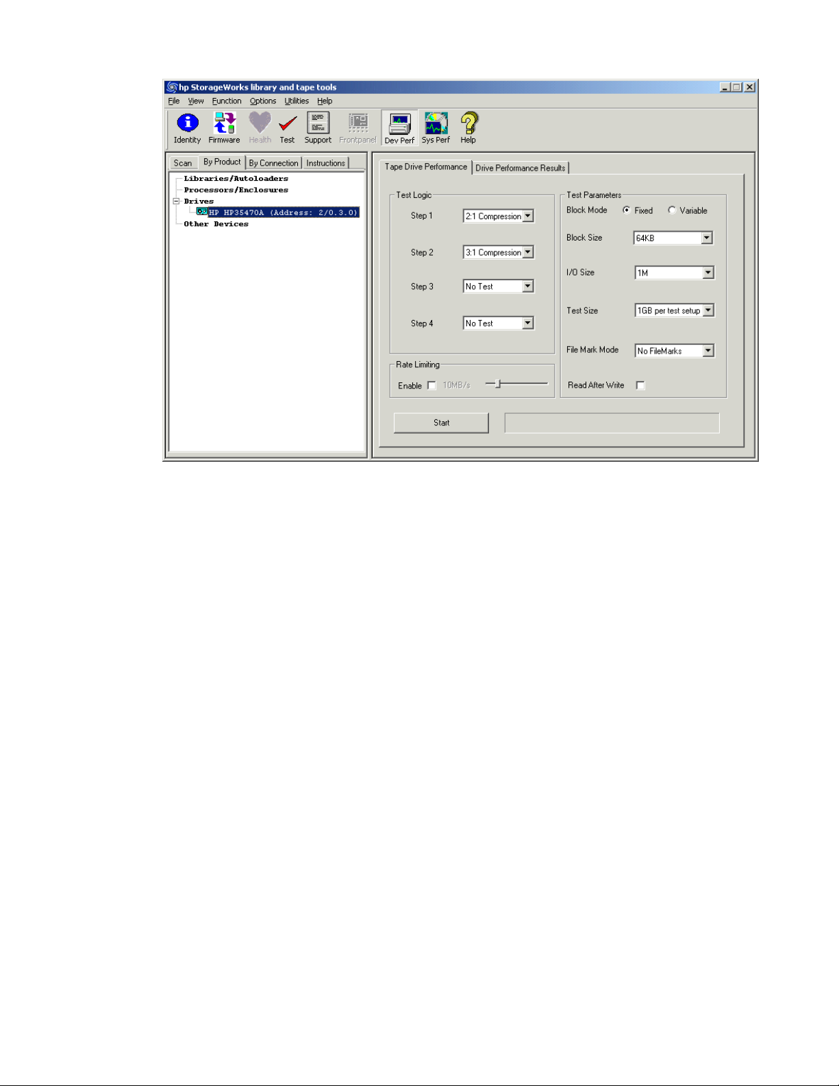
Figure 18 Drive Performance screen
3. In the Test Logic section of the screen, use the drop down m enus to select a data type for each
of
the four tests. The Drive Performance test is actually a series of four write/read subtests
(labeled
Step 1-4 on the Drive Performance screen) that measure performance using different
types of data that you can specify.
following data types can be selected:
The
•Zeros
• 1.6 :1 Compression
Compression (suggested starting value)
1
•2:
• 3:1 Compression
• 4:1 Compression
must specify a data type for Step 1, but you can choose not to perform Steps 2 through 4 by
u
Yo
lecting No Test (suggested starting value for steps 2 through 4 is
se
pecify the following additional parameters:
4. S
• Block Mode—Choose one of the following (suggested starting value is
No Test
).
Fixed
):
• Fixed—The test uses a fixed block size (length) that can b e specified in the Block Size
menu.
• Variable—The test uses a different mode of data transfer. When this option is selected,
the
Block Size menu is disabled.
• Block Size—If Block Mode is set to Fixed, specify the size of the data blocks used in the
test. Data blocks can be from 16K to 256K (suggested starting value is 64K).Thismenu is
disabled if Block Mode is set to Variable.
• I/O Size—The maximum amountofdatato betransferred by asingleread/write
operation. This length is typically a multiple of the Block Size and ranges from the specified
Block Size to 1MB (suggested starting value is 1MB).
• Test Size—The maximum amount of data written/read by the test. Valid choices are
1GB, 2GB, 4GB, 8GB, 16GB, 32GB, 64GB, 128GB, and Full Tape. Larger values increase
the time required to perform the test, but they produce more accurate test results (suggested
starting value is 4GB).
Library and Tape Tools User Guide
89
Page 90

• File Mark Mode—Instructs the test to write a filemark at the specified interval (1MB to
1GB). You can also instruct the test not to write any filemarks (suggested starting value is
No filemarks
).
NOTE:
Writing filemarks at a frequent interval will reduce the performance of the test.
• Read After Write—The test evaluates t wo sets of metrics when enabled, and one set
when disabled (suggested starting value is
disabled
). When enabled, data is written to the
tape and then the tape is read back. When disabled, only write performance is measured.
• Rate Limiting—If rate limiting is enabled, the I/O rate is limited to the specified value
(suggested starting value is
disabled
).
5. Click Start to perform the test. Progress of the test is displayed in the status bar to the right of the
Start button, and a dialog box will inform you when the test is complete.
6. Click the Drive Performance Results tab to view the results of the test.
To start the Drive Performance test (CSI version):
1. Use the select command to select thedevicetobetested.
select <n> (where <n> is the number of the device to be examined)
NOTE:
The devperf command is not available until you select a device.
2. From the Main screen, enter the devperf command to display the Device Performance Tool
Device Performance Tool screen displays several test options with their default
screen. T
he
settings.
Figure 19
Device Performance Tool screen
3. Chan
ge the
settings for one or more options. To change the settings, enter the number that
corresponds with the option that you want to change. Enter the new value at the prompt. The
five available options for this test are:
90
Tests and utility functions
Page 91

• Blocksize—Specify the blocksize, in bytes, to be written to the tape. Typical values a re
32768 (32KB), 65536 (64KB). The default is 65536.
• Repetitions—Specify how many write/read operations to perform. The default is 4096.
• Readback—Specify whether to enable the readback test after writing data to the device.
This option measures read performance in addition to write performance in MB/sec. This
option is disabled by default.
• Count—Specify howmanyblocks towrite to thetapedeviceper write operation. The
default is 16.
• Pattern—Specify the data pattern to be written to tape. Enter 2 for 2:1 compression ratio
or 3
for 3.1:1 compression ratio. The default is 2.
4. Use the start comma nd to start the test.
Library and Tape Tools User Guide
91
Page 92

Using the System Performance test
The System Performance Test has two modes: The backup pre-test measures the read performance of the
disk file system (simulating a backup), and the restore pre-test measures the write performance of the
disk file system (simulating a restore). Use these tests in conjunction with the Drive Performance Test to
identify any system bottlenecks. The backup pre-test is read-only and is safe to run on any part of your
file system.
test data for general backup testing.
Performing the System Performance Restore Pre-Test (GUI)
NOTE:
In the following procedure, a
necessarily default values, but they are general values thatwillresultina simple,representativetest. Use
them as a starting point, and modify them according to your needs.
1. Click Sys Perf on the main toolbar. The System Performance screen opens.
2. Click the Restore Pre-Test tab.
Figure 20 Restore Pre-Test tab of the System Performance screen
The restore pre-test creates data in the specified directory and can also be used to create
suggested starting value
is given for most parameters. These are not
3. Specify the following parame
• Test Path—Enter the destination directory to which the test will write data. This should
be a
directory on the backup server being tested. Make sure that the path is on the restore
destination disk to measure the real data rate. Use a directory name that you can find easily
such as C:\Test so that you ca
• Test Data Type—Select the type of da ta pattern to be written. Choose from the following
options:
•Fixed Byte
92
Tests and utility functions
ters:
easily delete the data later.
n
Page 93

•Incrementing
• Random
• Uncompressible Data
• 2:1 Compression Ratio (suggested starting value)
• 3:1 Compression Ratio
• 4:1 Compression Ratio
• File Size—Specify a range of possible file sizes for the test data (suggested starting
value is to use the default value).
• File Tree Depth—Specify the number of levels of subdirectories the program will create
from the specified directory (suggested starting value is 5).
• File Tree Breadth—Specify the number of directories to be created within each
subdirectory (suggested starting value is 5).
• Files Per Directory—Specify the number of files to be created within each
subdirectory (suggested starting value is 50).
NOTE:
The gauges in the Disc Capacity section of the screen show the amount of disk space required for
the
System Performance test using the current settings, and the amount of space available in the
indicated file system. If the required space exceeds the available space, the Test Size gauge displays
OVERFLOW,and youwill beunabletostart thetest.
4. Click Star t to perform the test. Progress of the test is displayed in the status bar to the right of the
Start button, and a dialog box will inform you when the test is complete.
5. Click the System Performance Results tab to view the test results.
Performing the System P erformance Backup Pre-Test
This test reads data from up to four separate locations on the file system. The reads are concurrent and
simulate up to four concurrent backup da ta streams. The performance of these reads is measured and
reported in the System Performance Results tab. Use this test to measure the performance of the file system
to be used for b a ckup. Use this test in conjunction with the Drive Performance Test to identify performance
bottlenecks in the system. This test is read-only and can be safely run on backup source data.
NOTE:
In the following procedure, a
necessarily default values, but they are general values that will result in a simple, representative test. Use
them as a starting point, and modify them according to your needs.
1. Click Sys Perf on the main toolbar. The System Performance screen opens.
2. Click the Backup Pre-Test tab.
suggested starting value
is given for each parameter. These are not
Library and Tape Tools User Guide
93
Page 94

Figure 21 Backup Pre-Test tab of the System Performance screen
3. Specify the following parameters:
• Read Size—Enter the maximum block size (in bytes) to transfer (suggested starting value
is
512K).
• Directory Traverse Method—Specify one of the following options (suggested starting
depth
value is
):
•Specify Depth to have the test read as far down the directory structure as possible
before moving laterally to the next directory.
•Specify Breadth to read all directories at the same level before moving down to the
next subdirectory level.
• Stop After—Specify a time limit for the test, or select “All Readers Complete” to continue
testing until the test is complete (suggested starting value is 5 minutes).
• Reader [1-4]—Enter up to four target directories from which the test will read data. For
each Reader, you must have first performed a Restore Pre-Test. Use the same directory or
directories that you specified in the Restore Pre-Tests.
The number of readers to use depends on your backup application. If the application uses
concurrent read streams, then select multiple readers. To guarantee an accurate measure of the
access rate of the real data, point each reader at the data that each stream will back up.
• Read Files—Specifies whether the files must be read back from the tape after the write
completes (suggested starting value is to select this option).
4. Click Start to perform the test. A dialog box will inform you when the test is complete.
5. Click the System Performance Results tab to view the test results.
94
Tests and utility functions
Page 95

Performing the System Performance Pre-Tests (CSI)
To start the CSI version of the System Performance Pre-Test:
NOTE:
The System Performance Pre-Tests (backup and restore) are not available for NetWare.
1. From the Main screen, enter the sysperf command to display the System Performance screen:
2. Enter one of the following commands for the pre-test you want to run:
• backup—Runs the Backup Pre-Test
• restore—Runs the Restore Pre-Test
3. To change the settings for one or more o ptions, enter the number that corresponds with the
option that you want to change. Enter the new value at the prompt.
Figure 22 B ackup Pre-Test screen (CSI)
The two options available for the B ackup Pre-Test are:
• Blocksize—Specify the blocksize (in bytes) to be read. Typical values are 32768 (32KB),
65536 (64KB). The default is 65536.
• Path—Specify the path to the directory to be read from.
Library and Tape Tools User Guide
95
Page 96

Figure 23 Restore Pre-Test screen (CSI)
The following options are available for the Restore Pre-Test:
• Filesize—Specify the size, in bytes, of the test files to be created.
• Number of
• Directory path—Specify the path of the directory where the test files will be written. This
should
restore destination disk to measure the real data rate. Use a directory name that you can find
easily s
• Pattern—Specify one of the following data patterns:
•Fixed byte
•Increme
• Random data
• 1.6 :1 compressible data
•2:1 com
• 3.1:1 compressible data
• 4.3:1 compressible data
4. Use th
e start command
Files—Specify the number of files to be created.
be a directory on the backup server being tested. Make sure that the path is on the
uch as C:\Test so that you can easily delete the data later.
nting byte
pressible data (suggested starting value)
to start the test.
Using the Dev i ce Analysis test
The Device Analysis test can be executed ma nually through the Tests screen or automatically whenever
a
support ticket is generated. The D evice Analysis test is unique among all the tests offered by L&TT.
In
addition to performing SCSI operations directly on a device, the Device Analysis test uses a set
of
predefined, device-specific rules to analyze device logs and configurations. If any known issues
are discovered during the analysis, the user is notified of the problem and the program suggests an
appropriate course of action.
The Device Analysis test automates failure analysis of a device by determining
• whethera knownorunknown problemwith a device exists
• if the problem can be resolved in the field through maintenance or simple repair
• whether a device ne eds to b e returned or serviced
96
Tests and utility functions
Page 97

Using the Read/Write test
The Read/Write test writes and reads data from tape and checks for accuracy. In addition to verifying
that the
fails if the err
read and write data independent of the storage application. This test is available for all tape drives.
CAUTION:
Use a blank tape when performing this test because this test is destructive to data on the tape.
The following options are available for this test:
• Test Time Limit—Specify the time limit in minutes. Enter 0 for no time limit.
• Data Limit Type—Specify one of the following options to limit the amount of data
• Data Size Limit—Specify the size limit in megabytes of data to be written/read in each
• Data Time Limit—Specify the time limit, in minutes, for each phase of the test.
• Block Size—Specify theblock size,inkilobytes,to beusedinthe test.
• Transfer Size Limit—Specify the m aximum data transfer limit, in kilobytes, per command.
• Block Transfer Type—Specify whether to use a fixed or variable block length.
• Data Pattern Type—Indicates the type of data pattern used in the test. Specify one of the
• Data Pattern—Specify a string value to use as a data pattern if the Data Pattern Type is
data read back matches the data written, the read/write error rates are also checked. The test
or rates exceed allowable limits. This test can be used to verify the ability of the drive to
written/read in each phase:
• Time—Limits the amount of data tested based on the time specified in Data Time Limit.
• Size—Limits the amount of data tested based on the size specified in Data Size Limit.
• Whole tape—Limits the amount of data tested based on the size of the tape.
phase.
following data pattern types:
• Pattern File—Uses a preset pattern
• Random—Generates random patterns
• User defined—Uses a user-defined string
set to “User Defined.”
Using the Move test
The Move Test performs a move command in a library or autoloader using source and destination
elements specified in the test options. When the move command completes, a second move command
returns the cartridge to its original location. This sequence can be repeated using an o ptional loop count.
The following options are available for this test:
• Loop count — Specify the number of times the test sequence should be repeated. Each test
sequence consists of t wo moves — one from the specified source to the specified destination
followed by a second move back to the original source location.
• Source address type — Specify one of the following source element address t ypes:
• Storage slot — The source address is a storage slot number (starting at 1).
• Drive — The source address is a drive number (starting at 1).
• Mail slot — The source address is a mail slot number (starting at 1).
• SCSI element address — The source address is a SCSI element number.
• Source address — A number indicating the source address. The m eaning of this number depends
on the
• Destination address type — Specify one of the following destination element address types:
• Storage slot — The destination address is a storage slot number (starting at 1).
specified Source address type.
Library and Tape Tools User Guide
97
Page 98

• Drive — The destination address is a drive number (starting at 1).
• Ma il slot — The destination address is a mail slot number (starting at 1).
• SCSI element address — The destination address is a SCSI element number.
• Destination address — A number indicating the destination ad dress. The meaning of this number
depends on the specified Destination address type.
Using the Medi
The Media Anal
exceeds the maximum allowable threshold, the test will require a cleaning cartridge and a second tape
to
determine if the problem is with the drive or the tape. No data is written to tape and the test is not
destructive to data. This test is useful if the user suspects that a backup failed because of a bad tape.
This test is a
The following options are available for this test:
• Test Time Limit—Specify the time limit in minutes. Enter 0 for no time limit.
• Data Limit T
in
each phase:
• Time—Limits the amount of data read based on the time specified in Data Time Limit.
• Size—Limi
• Whole tape—Limits the amount of data read based on the size of the tape.
• Amount of data read in each phase—Specify the size limit in megabytes of data to be
read in eac
• Time allowed for each data test phase—Specify the time limit, in minutes, for each
phase of the test.
• Transfer
aAnalysistest
ysis test reads data from the media and calculates the error rate. If the error rate
vailable for all tape drives.
ype—Specify one of the following options to limit the amount of data read
amount of data read based on the size specified in Data Size Limit.
ts the
hphase.
Size
Limit—Specify the maximum data transfer limit, in kilobytes, per command.
Using the Library Exerciser test
There are two versions of the Library Exerciser test depending on the model of the library or autoloader
being tested. The latest version of the Library Exerciser test is used on the MSL2024, MSL4048, EML, ESL
9000, and MSL 5000/6000 libraries, a nd the 1/8 G2 tape autoloader. Other library mo dels use a
previous version of the Library Exerciser test (see "Using the original version" on page 99).
Using the new version
By default, the new version of the Library Exerciser test verifies that the device robotics can access every
storage, and mail slot element in the library or autoloader by physically performing media moves
drive,
to
of the
NOTE:
This test can take a long time on very large libraries. If a shorter test is desired, use the test options
to
The test requires at least one piece of media in the storage and mail slot elem ents that are selected
for test. By default, the test attempts to verify media compatibility, so if multiple tape technologies or
generations are present in the library, one cartridge of each applicable type should be present. The
MSL2024 a nd MSL4048 libraries, and 1/8 G2 tape autoloader also require at least one empty element
in the
The following options are available for this test:
• Perform inventory at start of test—By default, this option is set to False because
98
location. Optionally, a subset of elements can be selected to focus the test on a specificarea
each
library or autoloader.
select a subset of elements to test.
selected storage and mail slot range.
the
inventory operation can take a long time on large libraries. If the inventory information needs
Tests and utility functions
Page 99

to be updated, setting this option to True causes an Initialize Element Status command
to be issued to the library at the start of the test.
• Test loop count (all operations except inventory)—Allows multiple loops of the test to be
run. The inventory operation (if selected) only runs p rior to the firstloop. The defaultvalue is 1.
• Test drive range (all, x-y,or none)—Specify the range of drives to be tested. Specify all to
test all drive elements. Specify none to skip all drive elements. Specify a single number (5,for
example) or a range (2-5, for example) to test specific d rive elements (numbering starts at 1).
• Test Import/Export range (all, x-y,or none)—Specify the range of import/export (mail
slot)
elements to be tested. Specify all to test all import/export elements. Specify none to skip all
import/export elements. Specify a sing le number (5, for example) or a range (2-5, for example)
to test
specific import/export elements (numbering starts at 1).
• Test slot range (all, x-y,or none)—Specify the range of slot (storage) elements to be tested.
Specify all to test all storage elements. Specify none to skip all storage elements. Specify a
single
number (5, for example) or a range (2-5, for example) to test specific storage elements
(numbering starts at 1).
• Ignore barcode labels and media types when selecting tapes—To ensure that
attempted moves are made only to elements that are compatible with the selected media, the
test attempts to use barcode label and/or Read Element Status information from the library to
determine media types by default. If barcode labels are missing or incorrect, it may be necessary
for this option to be set to True to allow the test to run. This option should only be set to True if all
of the media in the selected range is compatible with all of the elements in the selected range.
If this
option is set to True and more than one drive type is detected in the selected range, the
test will exit without moving media. The range options can be used to select ranges of elements
that
are known to be compatible.
Using
original version
the
brary Exerciser test takes a test cartridge from a mail slot a nd performs random slot-to-slot moves.
The Li
then moves the test cartridge into every available drive and performs a short drive test. This test is
st
The te
intended to exercise the robotics and robot drive hardware.
NOTE:
Not all libraries are supported by the Library Exerciser test. If the test is not displayed in the list of
then the selected device is not supported.
,
tests
The following options are available for this test:
• Test Time Limit—Specify the time limit in minutes. Enter 0 for no time limit. The default
setting is 0.
• Move Command Timeout—Specify the maximum time allotted, in seconds, for each move
command before failure. The default is 600 seconds.
• Active Slot Range—Specify arange of slotstobetested. Enterarangeofslotnumbers
separated with a dash (for example: 2-5), or enter all to specify all slots. The default is all.
• Active Drive Range—Specify a range of drives to be tested. Enter a range of drives
separated with a dash (for example: 2-5), or enter all to specify all drives. The default is all.
• Drive Type Option—Specify thetypeofdrivestobetested(in librariesthathave mixed drive
types). Enter the type of drive (for example: LTO or DLT), or enter all to test all drive types.
The default is all.
• Check Inventory Mode—Specify whether to perform an active inventory check at beginning
of the test. The active inventory check can take a long time to p er form. The default is on.
• Barcode Mode—Specify how barcodes are handled. Choose one of the following options:
• Show all—Shows all b arcodes
• Show suspect—Shows only suspect barcodes (default)
• Off—Does not show barcodes
• Slot-to-Slot Moves—Select one of the following options for the slot-to-slot test:
Library and Tape Tools User Guide
99
Page 100

• All—Moves all cartridges
• Random—Moves randomly selected cartridges (default)
• Off—No cartridges are moved
• Random Coverage—When Slot-to-Slot Moves is set to Random, specify the percentage of units
covered during random test. The default is 20%.
• Drive Load Mode—Specify whether or not to perform the Drive Load test. The default setting
is
on.
• Drive Test Option—If the Drive Load test is enabled, specify one of the following options:
•Off
• Data loop back (default)
• Read-only
• Read/write
• Cartridge Load Test—Specify one of the following options for the Cartridge Load test:
•Off (default)
•Single drive
• Multiple drives
•All drives
• CM Integrity Mode—Specify whether to enable the CM integrity check option for LTO drives.
The default setting is on.
Using the utility functions
Utility functions execute the SCSI utility scripts (files with a .scc extension) stored in the scripts
directory. These scripts send various SCSI commands to the selected device, but they generally do
not
Many of the utility functions are device-specific and intended only to remedy specificproblemsthatmay
occur with a particular device.
CAUTION
Using a s
inopera
or
To use a utility function with the Windows version of L&TT:
1. Select Run Script... from the Utilities menu to display the Run Script dialog.
2. In the Devices section, click the check box next to the device on which you want to run the script.
3. Click Browse to select a script file to execute. The utility scripts are located in the scripts
4. Select a script and click Open to return to the Run Script dialog.
5. Click Run Script.
When the script has completed, the Script Output and Script Execution Log text boxes display relevant
information.
To use a utility function from the CSI:
1. On the Main screen, enter the number corresponding to the device that you want to test. The
2. Enter the runscript command to display the Run Script screen.
3. Enter 1 to specify the script path.
nany results.
retur
:
cript improperly or when it is not required can cause harm—possibly rendering a device
ble. Do not attempt to use these utility functions unless you are very familiar with SCSI operation,
you have been advised to do so by a technical support representative or a Device Analysis script.
Thedevicelogical name is nowassigned.
directory and have an .scc extension.
Device Information screen opens.
100
Tests and utility functions
 Loading...