

Page 1

User Guide
hp StorageWorks
IP Storage Router
SR2122-2
Product Version: 2.0
Third Edition (December 2003)
Part Number: 304835-003
This user guide provides instructional information for installing and configuring the HP
StorageWorks IP Storage Router SR2122-2.
Page 2

© Copyright 2002–2003 Hewlett-Packard Development Company, L.P.
Hewlett-Packard Company makes no warranty of any kind with regard to this material, including, but not limited to,
the implied warranties of merchantability and fitness for a particular purpose. Hewlett-Packard shall not be liable for
errors contained herein or for incidental or consequential damages in connection with the furnishing, performance,
or use of this material.
This document contains proprietary information, which is protected by copyright. No part of this document may be
photocopied, reproduced, or translated into another language without the prior written consent of Hewlett-Packard.
The information contained in this document is subject to change without notice.
Microsoft, MS-DOS®, MS Windows®, Windows®, and Windows NT® are U.S. registered trademarks of Microsoft
Corporation.
UNIX® is a registered trademark of The Open Group.
Hewlett-Packard Company shall not be liable for technical or editorial errors or omissions contained herein. The
information is provided “as is” without warranty of any kind and is subject to change without notice. The warranties
for Hewlett-Packard Company products are set forth in the express limited warranty statements for such products.
Nothing herein should be construed as constituting an additional warranty.
Printed in the U.S.A.
IP Storage Router SR2122-2 User Guide
Third Edition (December 2003)
Part Number: 304835-003
Page 3

Contents
About this Guide. . . . . . . . . . . . . . . . . . . . . . . . . . . . . . . . . . . . . . . . . . . . . . . . . . .13
Overview. . . . . . . . . . . . . . . . . . . . . . . . . . . . . . . . . . . . . . . . . . . . . . . . . . . . . . . . . . . . . . . . . 14
Intended Audience . . . . . . . . . . . . . . . . . . . . . . . . . . . . . . . . . . . . . . . . . . . . . . . . . . . . . . 14
Prerequisites . . . . . . . . . . . . . . . . . . . . . . . . . . . . . . . . . . . . . . . . . . . . . . . . . . . . . . . . . . . 14
Related Documentation . . . . . . . . . . . . . . . . . . . . . . . . . . . . . . . . . . . . . . . . . . . . . . . . . . 14
Conventions . . . . . . . . . . . . . . . . . . . . . . . . . . . . . . . . . . . . . . . . . . . . . . . . . . . . . . . . . . . . . . 15
Document Conventions . . . . . . . . . . . . . . . . . . . . . . . . . . . . . . . . . . . . . . . . . . . . . . . . . . 15
Text Symbols . . . . . . . . . . . . . . . . . . . . . . . . . . . . . . . . . . . . . . . . . . . . . . . . . . . . . . . . . . 15
Equipment Symbols . . . . . . . . . . . . . . . . . . . . . . . . . . . . . . . . . . . . . . . . . . . . . . . . . . . . . 16
Rack Stability . . . . . . . . . . . . . . . . . . . . . . . . . . . . . . . . . . . . . . . . . . . . . . . . . . . . . . . . . . . . . 17
Getting Help . . . . . . . . . . . . . . . . . . . . . . . . . . . . . . . . . . . . . . . . . . . . . . . . . . . . . . . . . . . . . . 18
HP Technical Support . . . . . . . . . . . . . . . . . . . . . . . . . . . . . . . . . . . . . . . . . . . . . . . . . . . 18
HP Storage Website . . . . . . . . . . . . . . . . . . . . . . . . . . . . . . . . . . . . . . . . . . . . . . . . . . . . . 18
HP Authorized Reseller . . . . . . . . . . . . . . . . . . . . . . . . . . . . . . . . . . . . . . . . . . . . . . . . . . 18
1 Product Overview . . . . . . . . . . . . . . . . . . . . . . . . . . . . . . . . . . . . . . . . . . . . . . . . . .19
Basic Description . . . . . . . . . . . . . . . . . . . . . . . . . . . . . . . . . . . . . . . . . . . . . . . . . . . . . . . . . . 20
Port Descriptions . . . . . . . . . . . . . . . . . . . . . . . . . . . . . . . . . . . . . . . . . . . . . . . . . . . . . . . . . . 21
Gigabit Ethernet Ports . . . . . . . . . . . . . . . . . . . . . . . . . . . . . . . . . . . . . . . . . . . . . . . . . . . 21
Console Port. . . . . . . . . . . . . . . . . . . . . . . . . . . . . . . . . . . . . . . . . . . . . . . . . . . . . . . . . . . 22
10/100 Ethernet Management Port. . . . . . . . . . . . . . . . . . . . . . . . . . . . . . . . . . . . . . . . . . 22
10/100 Ethernet HA Port . . . . . . . . . . . . . . . . . . . . . . . . . . . . . . . . . . . . . . . . . . . . . . . . . 22
Fibre Channel Ports . . . . . . . . . . . . . . . . . . . . . . . . . . . . . . . . . . . . . . . . . . . . . . . . . . . . . 22
Front-Panel LEDs . . . . . . . . . . . . . . . . . . . . . . . . . . . . . . . . . . . . . . . . . . . . . . . . . . . . . . . . . . 23
Fan Assembly . . . . . . . . . . . . . . . . . . . . . . . . . . . . . . . . . . . . . . . . . . . . . . . . . . . . . . . . . . . . . 25
Power Supply . . . . . . . . . . . . . . . . . . . . . . . . . . . . . . . . . . . . . . . . . . . . . . . . . . . . . . . . . . . . . 26
Contents
3IP Storage Router SR2122-2 User Guide
Page 4

Contents
2 Installation . . . . . . . . . . . . . . . . . . . . . . . . . . . . . . . . . . . . . . . . . . . . . . . . . . . . . . .27
Site Planning. . . . . . . . . . . . . . . . . . . . . . . . . . . . . . . . . . . . . . . . . . . . . . . . . . . . . . . . . . . . . . 28
Installing the Storage Router . . . . . . . . . . . . . . . . . . . . . . . . . . . . . . . . . . . . . . . . . . . . . . . . . 28
Installing on a Table or a Shelf . . . . . . . . . . . . . . . . . . . . . . . . . . . . . . . . . . . . . . . . . . . . 29
Rack-Mounting the Storage Router . . . . . . . . . . . . . . . . . . . . . . . . . . . . . . . . . . . . . . . . . 29
Installing SFP Modules. . . . . . . . . . . . . . . . . . . . . . . . . . . . . . . . . . . . . . . . . . . . . . . . . . . . . . 33
Mylar Tab SFP Modules . . . . . . . . . . . . . . . . . . . . . . . . . . . . . . . . . . . . . . . . . . . . . . . . . 36
Actuator/Button SFP Modules. . . . . . . . . . . . . . . . . . . . . . . . . . . . . . . . . . . . . . . . . . . . . 38
Bale Clasp SFP Modules . . . . . . . . . . . . . . . . . . . . . . . . . . . . . . . . . . . . . . . . . . . . . . . . . 40
Connecting to Gigabit Ethernet and Fibre Channel Ports . . . . . . . . . . . . . . . . . . . . . . . . . . . 42
Connecting to a Gigabit Ethernet Port . . . . . . . . . . . . . . . . . . . . . . . . . . . . . . . . . . . . . . . 43
Connecting to a Fibre Channel Port . . . . . . . . . . . . . . . . . . . . . . . . . . . . . . . . . . . . . . . . . 43
Connecting to the 10/100 Ethernet Management and HA Ports. . . . . . . . . . . . . . . . . . . . . . . 43
Connecting to the Console Port . . . . . . . . . . . . . . . . . . . . . . . . . . . . . . . . . . . . . . . . . . . . . . . 44
Connecting Power. . . . . . . . . . . . . . . . . . . . . . . . . . . . . . . . . . . . . . . . . . . . . . . . . . . . . . . . . . 46
Verifying Installation . . . . . . . . . . . . . . . . . . . . . . . . . . . . . . . . . . . . . . . . . . . . . . . . . . . . . . . 47
Verifying Startup Operations . . . . . . . . . . . . . . . . . . . . . . . . . . . . . . . . . . . . . . . . . . . . . . 47
Verify that Network Connections are Operational. . . . . . . . . . . . . . . . . . . . . . . . . . . . . . 47
Verify That Fibre Channel Connections are Operational . . . . . . . . . . . . . . . . . . . . . . . . 48
Where to Go Next. . . . . . . . . . . . . . . . . . . . . . . . . . . . . . . . . . . . . . . . . . . . . . . . . . . . . . . . . . 48
3 Troubleshooting . . . . . . . . . . . . . . . . . . . . . . . . . . . . . . . . . . . . . . . . . . . . . . . . . . .49
Solving Problems at the Component Level . . . . . . . . . . . . . . . . . . . . . . . . . . . . . . . . . . . . . . 50
Identifying Startup Problems . . . . . . . . . . . . . . . . . . . . . . . . . . . . . . . . . . . . . . . . . . . . . . . . . 51
Troubleshooting the Power Supply . . . . . . . . . . . . . . . . . . . . . . . . . . . . . . . . . . . . . . . . . . . . 52
Troubleshooting a Network or Fibre Channel Port Connection. . . . . . . . . . . . . . . . . . . . . . . 53
Troubleshooting a Connection to a Gigabit Ethernet Port. . . . . . . . . . . . . . . . . . . . . . . . 53
Troubleshooting a Connection to a 10/100 Ethernet Management or
10/100 Ethernet HA Port . . . . . . . . . . . . . . . . . . . . . . . . . . . . . . . . . . . . . . . . . . . . . . . . . 54
Troubleshooting a Connection to a Fibre Channel Port. . . . . . . . . . . . . . . . . . . . . . . . . . 55
Contacting Customer Service . . . . . . . . . . . . . . . . . . . . . . . . . . . . . . . . . . . . . . . . . . . . . . . . . 56
4 Software Overview . . . . . . . . . . . . . . . . . . . . . . . . . . . . . . . . . . . . . . . . . . . . . . . . .57
Storage Router Overview . . . . . . . . . . . . . . . . . . . . . . . . . . . . . . . . . . . . . . . . . . . . . . . . . . . . 58
SCSI Routing Overview . . . . . . . . . . . . . . . . . . . . . . . . . . . . . . . . . . . . . . . . . . . . . . . . . . . . . 61
Routing SCSI Requests and Responses . . . . . . . . . . . . . . . . . . . . . . . . . . . . . . . . . . . . . . 62
Basic Network Structure . . . . . . . . . . . . . . . . . . . . . . . . . . . . . . . . . . . . . . . . . . . . . . . . . 63
SCSI Routing Mapping and Access Control . . . . . . . . . . . . . . . . . . . . . . . . . . . . . . . . . . 64
Available Instances of SCSI Routing. . . . . . . . . . . . . . . . . . . . . . . . . . . . . . . . . . . . . . . . 68
4 IP Storage Router SR2122-2 User Guide
Page 5

Contents
FCIP Overview . . . . . . . . . . . . . . . . . . . . . . . . . . . . . . . . . . . . . . . . . . . . . . . . . . . . . . . . . . . . 69
Using FCIP to Route Fibre Channel Packets . . . . . . . . . . . . . . . . . . . . . . . . . . . . . . . . . . 69
FCIP Network Structures. . . . . . . . . . . . . . . . . . . . . . . . . . . . . . . . . . . . . . . . . . . . . . . . . 71
Mixed Mode Overview. . . . . . . . . . . . . . . . . . . . . . . . . . . . . . . . . . . . . . . . . . . . . . . . . . . . . . 74
Basic Network Structure . . . . . . . . . . . . . . . . . . . . . . . . . . . . . . . . . . . . . . . . . . . . . . . . . 75
VLAN Access Overview . . . . . . . . . . . . . . . . . . . . . . . . . . . . . . . . . . . . . . . . . . . . . . . . . . . . 75
Gigabit Ethernet Interface Overview . . . . . . . . . . . . . . . . . . . . . . . . . . . . . . . . . . . . . . . . . . . 77
Authentication Overview . . . . . . . . . . . . . . . . . . . . . . . . . . . . . . . . . . . . . . . . . . . . . . . . . . . . 78
Cluster Management Overview . . . . . . . . . . . . . . . . . . . . . . . . . . . . . . . . . . . . . . . . . . . . . . . 79
Interface Naming . . . . . . . . . . . . . . . . . . . . . . . . . . . . . . . . . . . . . . . . . . . . . . . . . . . . . . . . . . 80
5 Configuring the Storage Router . . . . . . . . . . . . . . . . . . . . . . . . . . . . . . . . . . . . . . . .81
Prerequisite Tasks. . . . . . . . . . . . . . . . . . . . . . . . . . . . . . . . . . . . . . . . . . . . . . . . . . . . . . . . . . 82
Collecting Configuration Information . . . . . . . . . . . . . . . . . . . . . . . . . . . . . . . . . . . . . . . . . . 82
Connecting a Console. . . . . . . . . . . . . . . . . . . . . . . . . . . . . . . . . . . . . . . . . . . . . . . . . . . . . . . 87
Initial System Configuration Script . . . . . . . . . . . . . . . . . . . . . . . . . . . . . . . . . . . . . . . . . . . . 88
Running the Setup Configuration Wizard . . . . . . . . . . . . . . . . . . . . . . . . . . . . . . . . . . . . . . . 89
Introducing the CLI . . . . . . . . . . . . . . . . . . . . . . . . . . . . . . . . . . . . . . . . . . . . . . . . . . . . . . . . 91
Character Case Sensitivity in the CLI . . . . . . . . . . . . . . . . . . . . . . . . . . . . . . . . . . . . . . . 91
Command Modes . . . . . . . . . . . . . . . . . . . . . . . . . . . . . . . . . . . . . . . . . . . . . . . . . . . . . . . 91
Command Prompt . . . . . . . . . . . . . . . . . . . . . . . . . . . . . . . . . . . . . . . . . . . . . . . . . . . . . . 92
Reserved Words . . . . . . . . . . . . . . . . . . . . . . . . . . . . . . . . . . . . . . . . . . . . . . . . . . . . . . . . 92
Show CLI Command . . . . . . . . . . . . . . . . . . . . . . . . . . . . . . . . . . . . . . . . . . . . . . . . . . . . 92
Special Keys. . . . . . . . . . . . . . . . . . . . . . . . . . . . . . . . . . . . . . . . . . . . . . . . . . . . . . . . . . . 93
Starting a CLI Management Session . . . . . . . . . . . . . . . . . . . . . . . . . . . . . . . . . . . . . . . . 94
Introducing the Web-Based GUI . . . . . . . . . . . . . . . . . . . . . . . . . . . . . . . . . . . . . . . . . . . . . . 94
Logging In . . . . . . . . . . . . . . . . . . . . . . . . . . . . . . . . . . . . . . . . . . . . . . . . . . . . . . . . . . . . 94
Monitor Mode . . . . . . . . . . . . . . . . . . . . . . . . . . . . . . . . . . . . . . . . . . . . . . . . . . . . . . . . . 95
Administrator Mode. . . . . . . . . . . . . . . . . . . . . . . . . . . . . . . . . . . . . . . . . . . . . . . . . . . . . 95
Menu Items and Links . . . . . . . . . . . . . . . . . . . . . . . . . . . . . . . . . . . . . . . . . . . . . . . . . . . 95
6 Configuring System Parameters . . . . . . . . . . . . . . . . . . . . . . . . . . . . . . . . . . . . . . . .97
Prerequisite Tasks. . . . . . . . . . . . . . . . . . . . . . . . . . . . . . . . . . . . . . . . . . . . . . . . . . . . . . . . . . 98
Configuration Tasks . . . . . . . . . . . . . . . . . . . . . . . . . . . . . . . . . . . . . . . . . . . . . . . . . . . . . . . . 98
Configuring the Management Interface . . . . . . . . . . . . . . . . . . . . . . . . . . . . . . . . . . . . . . . . . 99
Configuring Time and Date . . . . . . . . . . . . . . . . . . . . . . . . . . . . . . . . . . . . . . . . . . . . . . . . . 101
Configuring IP Routes . . . . . . . . . . . . . . . . . . . . . . . . . . . . . . . . . . . . . . . . . . . . . . . . . . . . . 102
Static Routes . . . . . . . . . . . . . . . . . . . . . . . . . . . . . . . . . . . . . . . . . . . . . . . . . . . 102
Dynamic Routes via RIP Listening. . . . . . . . . . . . . . . . . . . . . . . . . . . . . . . . . . 102
5IP Storage Router SR2122-2 User Guide
Page 6

Contents
Configuring Network Management Access . . . . . . . . . . . . . . . . . . . . . . . . . . . . . . . . . . . . . 104
Configuring Passwords. . . . . . . . . . . . . . . . . . . . . . . . . . . . . . . . . . . . . . . . . . . . . . . . . . . . . 105
Configuring Administrator Contact Information . . . . . . . . . . . . . . . . . . . . . . . . . . . . . . . . . 105
Configuring the High-Availability Interface . . . . . . . . . . . . . . . . . . . . . . . . . . . . . . . . . . . . 106
Configuring for Secure Shell (SSH) Access. . . . . . . . . . . . . . . . . . . . . . . . . . . . . . . . . . . . . 107
Configuring for iSNS Communications . . . . . . . . . . . . . . . . . . . . . . . . . . . . . . . . . . . . . . . . 108
Verifying and Saving Configuration . . . . . . . . . . . . . . . . . . . . . . . . . . . . . . . . . . . . . . . . . . 109
7 Configuring VLAN. . . . . . . . . . . . . . . . . . . . . . . . . . . . . . . . . . . . . . . . . . . . . . . . .111
Prerequisite Tasks. . . . . . . . . . . . . . . . . . . . . . . . . . . . . . . . . . . . . . . . . . . . . . . . . . . . . . . . . 112
VLAN Encapsulation . . . . . . . . . . . . . . . . . . . . . . . . . . . . . . . . . . . . . . . . . . . . . . . . . . . . . . 112
Configuration Tasks . . . . . . . . . . . . . . . . . . . . . . . . . . . . . . . . . . . . . . . . . . . . . . . . . . . . . . . 112
Configuring for VLAN with VTP . . . . . . . . . . . . . . . . . . . . . . . . . . . . . . . . . . . . . . . . . . . . 114
Configuring for VLAN without VTP . . . . . . . . . . . . . . . . . . . . . . . . . . . . . . . . . . . . . . . . . . 115
Configuring an IP Route. . . . . . . . . . . . . . . . . . . . . . . . . . . . . . . . . . . . . . . . . . . . . . . . . . . . 116
Verifying and Saving Configuration . . . . . . . . . . . . . . . . . . . . . . . . . . . . . . . . . . . . . . . . . . 116
Assigning a VLAN to a SCSI Routing Instance. . . . . . . . . . . . . . . . . . . . . . . . . . . . . . . . . . 118
8 Configuring SCSI Routing . . . . . . . . . . . . . . . . . . . . . . . . . . . . . . . . . . . . . . . . . . .119
Prerequisite Tasks. . . . . . . . . . . . . . . . . . . . . . . . . . . . . . . . . . . . . . . . . . . . . . . . . . . . . . . . . 120
Configuration Tasks . . . . . . . . . . . . . . . . . . . . . . . . . . . . . . . . . . . . . . . . . . . . . . . . . . . . . . . 120
Creating a SCSI Routing Instance . . . . . . . . . . . . . . . . . . . . . . . . . . . . . . . . . . . . . . . . . . . . 125
Configuring a Server Interface . . . . . . . . . . . . . . . . . . . . . . . . . . . . . . . . . . . . . . . . . . . . . . . 125
Without VLAN. . . . . . . . . . . . . . . . . . . . . . . . . . . . . . . . . . . . . . . . . . . . . . . . . . . . . . . . 125
With VLAN . . . . . . . . . . . . . . . . . . . . . . . . . . . . . . . . . . . . . . . . . . . . . . . . . . . . . . . . . . 126
Configuring iSCSI Targets . . . . . . . . . . . . . . . . . . . . . . . . . . . . . . . . . . . . . . . . . . . . . . . . . . 126
Target-and-LUN mapping using WWPN addressing . . . . . . . . . . . . . . . . . . . . . . . . . . 127
Target-and-LUN mapping using LUNWWN addressing . . . . . . . . . . . . . . . . . . . . . . . 128
Target-and-LUN mapping using Serial Number addressing . . . . . . . . . . . . . . . . . . . . . 128
Target-only mapping using WWPN addressing . . . . . . . . . . . . . . . . . . . . . . . . . . . . . . 129
Configuring an Access List . . . . . . . . . . . . . . . . . . . . . . . . . . . . . . . . . . . . . . . . . . . . . . . . . 129
Configuring Access . . . . . . . . . . . . . . . . . . . . . . . . . . . . . . . . . . . . . . . . . . . . . . . . . . . . . . . 132
Access an iSCSI target by IP hosts identified in an access list . . . . . . . . . . . . . . . . . . . 132
Access an iSCSI target by all IP hosts . . . . . . . . . . . . . . . . . . . . . . . . . . . . . . . . . . . . . . 133
Access all iSCSI targets by IP hosts identified in an access list . . . . . . . . . . . . . . . . . . 133
Access all iSCSI targets by all IP hosts . . . . . . . . . . . . . . . . . . . . . . . . . . . . . . . . . . . . . 133
Access denied to one iSCSI target . . . . . . . . . . . . . . . . . . . . . . . . . . . . . . . . . . . . . . . . . 133
Access denied to all iSCSI targets . . . . . . . . . . . . . . . . . . . . . . . . . . . . . . . . . . . . . . . . . 134
Verifying and Saving Configuration . . . . . . . . . . . . . . . . . . . . . . . . . . . . . . . . . . . . . . . . . . 134
Default Values For FC Interfaces. . . . . . . . . . . . . . . . . . . . . . . . . . . . . . . . . . . . . . . . . . . . . 136
6 IP Storage Router SR2122-2 User Guide
Page 7

Contents
9 Configuring FCIP. . . . . . . . . . . . . . . . . . . . . . . . . . . . . . . . . . . . . . . . . . . . . . . . . .137
Prerequisite Tasks. . . . . . . . . . . . . . . . . . . . . . . . . . . . . . . . . . . . . . . . . . . . . . . . . . . . . . . . . 137
Configuration Tasks . . . . . . . . . . . . . . . . . . . . . . . . . . . . . . . . . . . . . . . . . . . . . . . . . . . . . . . 138
Creating an FCIP Instance . . . . . . . . . . . . . . . . . . . . . . . . . . . . . . . . . . . . . . . . . . . . . . . . . . 138
Assigning an IP Address . . . . . . . . . . . . . . . . . . . . . . . . . . . . . . . . . . . . . . . . . . . . . . . . . . . 139
Assigning a Peer Name and Peer IP Address . . . . . . . . . . . . . . . . . . . . . . . . . . . . . . . . . . . . 139
Understanding Flow Control . . . . . . . . . . . . . . . . . . . . . . . . . . . . . . . . . . . . . . . . . . 139
Understanding Error Recovery . . . . . . . . . . . . . . . . . . . . . . . . . . . . . . . . . . . . . . . . 139
TCP Protocol . . . . . . . . . . . . . . . . . . . . . . . . . . . . . . . . . . . . . . . . . . . . . . . . . . . . . . 139
TCP Client. . . . . . . . . . . . . . . . . . . . . . . . . . . . . . . . . . . . . . . . . . . . . . . . . . . . . 140
TCP Server . . . . . . . . . . . . . . . . . . . . . . . . . . . . . . . . . . . . . . . . . . . . . . . . . . . . 140
Configuring Operational Parameters . . . . . . . . . . . . . . . . . . . . . . . . . . . . . . . . . . . . . . . . . . 141
Verifying and Saving Configuration . . . . . . . . . . . . . . . . . . . . . . . . . . . . . . . . . . . . . . . . . . 142
10 Configuring Authentication . . . . . . . . . . . . . . . . . . . . . . . . . . . . . . . . . . . . . . . . . .145
Prerequisite Tasks. . . . . . . . . . . . . . . . . . . . . . . . . . . . . . . . . . . . . . . . . . . . . . . . . . . . . . . . . 146
Using iSCSI Authentication . . . . . . . . . . . . . . . . . . . . . . . . . . . . . . . . . . . . . . . . . . . . . . . . . 146
AAA Security Services. . . . . . . . . . . . . . . . . . . . . . . . . . . . . . . . . . . . . . . . . . . . . . . . . . . . . 146
Configuration Tasks . . . . . . . . . . . . . . . . . . . . . . . . . . . . . . . . . . . . . . . . . . . . . . . . . . . . . . . 147
Configuring Security Services . . . . . . . . . . . . . . . . . . . . . . . . . . . . . . . . . . . . . . . . . . . . . . . 150
RADIUS Servers . . . . . . . . . . . . . . . . . . . . . . . . . . . . . . . . . . . . . . . . . . . . . . . . . . . . . . 150
TACACS+ Hosts . . . . . . . . . . . . . . . . . . . . . . . . . . . . . . . . . . . . . . . . . . . . . . . . . . . . . . 151
Local Username Database . . . . . . . . . . . . . . . . . . . . . . . . . . . . . . . . . . . . . . . . . . . . . . . 151
Building the AAA Authentication List. . . . . . . . . . . . . . . . . . . . . . . . . . . . . . . . . . . . . . . . . 153
Testing iSCSI Authentication . . . . . . . . . . . . . . . . . . . . . . . . . . . . . . . . . . . . . . . . . . . . . . . . 154
Enabling iSCSI Authentication. . . . . . . . . . . . . . . . . . . . . . . . . . . . . . . . . . . . . . . . . . . . . . . 154
Verifying and Saving Configuration . . . . . . . . . . . . . . . . . . . . . . . . . . . . . . . . . . . . . . . . . . 155
11 Configuring a High Availability Cluster . . . . . . . . . . . . . . . . . . . . . . . . . . . . . . . . .157
Prerequisite Tasks. . . . . . . . . . . . . . . . . . . . . . . . . . . . . . . . . . . . . . . . . . . . . . . . . . . . . . . . . 158
Adding the Storage Router to a Cluster . . . . . . . . . . . . . . . . . . . . . . . . . . . . . . . . . . . . . . . . 158
Adding an Unconfigured Storage Router. . . . . . . . . . . . . . . . . . . . . . . . . . . . . . . . . . . . 159
Adding a Minimally Configured Storage Router. . . . . . . . . . . . . . . . . . . . . . . . . . . . . . 160
Adding Completely Configured Storage Routers . . . . . . . . . . . . . . . . . . . . . . . . . . . . . 162
Changing Clusters. . . . . . . . . . . . . . . . . . . . . . . . . . . . . . . . . . . . . . . . . . . . . . . . . . . . . . . . . 163
7IP Storage Router SR2122-2 User Guide
Page 8

Contents
12 Maintaining and Managing the Storage Router . . . . . . . . . . . . . . . . . . . . . . . . . . .165
Prerequisite Tasks. . . . . . . . . . . . . . . . . . . . . . . . . . . . . . . . . . . . . . . . . . . . . . . . . . . . . . . . . 166
Installing Updated Software . . . . . . . . . . . . . . . . . . . . . . . . . . . . . . . . . . . . . . . . . . . . . . . . . 166
Specifying the Location to Retrieve Updated Software. . . . . . . . . . . . . . . . . . . . . . . . . 168
Using HTTP. . . . . . . . . . . . . . . . . . . . . . . . . . . . . . . . . . . . . . . . . . . . . . . . . . . . . . . 169
Using Proxy Services. . . . . . . . . . . . . . . . . . . . . . . . . . . . . . . . . . . . . . . . . . . . . . . . 169
Using TFTP . . . . . . . . . . . . . . . . . . . . . . . . . . . . . . . . . . . . . . . . . . . . . . . . . . . . . . . 170
Downloading Updated Software . . . . . . . . . . . . . . . . . . . . . . . . . . . . . . . . . . . . . . . . . . 170
Using HTTP. . . . . . . . . . . . . . . . . . . . . . . . . . . . . . . . . . . . . . . . . . . . . . . . . . . . . . . 171
Using Proxy Services. . . . . . . . . . . . . . . . . . . . . . . . . . . . . . . . . . . . . . . . . . . . . . . . 171
Using TFTP . . . . . . . . . . . . . . . . . . . . . . . . . . . . . . . . . . . . . . . . . . . . . . . . . . . . . . . 172
Setting Updated Software as Boot Version . . . . . . . . . . . . . . . . . . . . . . . . . . . . . . . . . . 173
Precautions for Cluster Environments . . . . . . . . . . . . . . . . . . . . . . . . . . . . . . . . . . . . . . 173
Backing Up System Configuration. . . . . . . . . . . . . . . . . . . . . . . . . . . . . . . . . . . . . . . . . . . . 174
Creating Local Backups. . . . . . . . . . . . . . . . . . . . . . . . . . . . . . . . . . . . . . . . . . . . . . . . . 174
Storing Backups to a Remote TFTP Server . . . . . . . . . . . . . . . . . . . . . . . . . . . . . . . . . . 175
Restoring from Backups . . . . . . . . . . . . . . . . . . . . . . . . . . . . . . . . . . . . . . . . . . . . . . . . . . . . 175
Restoring a Deleted SCSI Routing Instance . . . . . . . . . . . . . . . . . . . . . . . . . . . . . . . . . 176
Restoring an Existing SCSI Routing Instance . . . . . . . . . . . . . . . . . . . . . . . . . . . . . . . . 177
Restoring an Access List . . . . . . . . . . . . . . . . . . . . . . . . . . . . . . . . . . . . . . . . . . . . . . . . 178
Restoring AAA Authentication Information . . . . . . . . . . . . . . . . . . . . . . . . . . . . . . . . . 179
Restoring VLANs. . . . . . . . . . . . . . . . . . . . . . . . . . . . . . . . . . . . . . . . . . . . . . . . . . . . . . 180
Restoring System Configuration . . . . . . . . . . . . . . . . . . . . . . . . . . . . . . . . . . . . . . . . . . 181
Powering Down the Storage Router . . . . . . . . . . . . . . . . . . . . . . . . . . . . . . . . . . . . . . . . . . . 183
Resetting the System. . . . . . . . . . . . . . . . . . . . . . . . . . . . . . . . . . . . . . . . . . . . . . . . . . . . . . . 183
Reset All to Factory Defaults. . . . . . . . . . . . . . . . . . . . . . . . . . . . . . . . . . . . . . . . . . . . . 184
Reset and Retain System Settings . . . . . . . . . . . . . . . . . . . . . . . . . . . . . . . . . . . . . . . . . 185
Reset to Remove Saved Configuration Files . . . . . . . . . . . . . . . . . . . . . . . . . . . . . . . . . 186
Recovering Passwords . . . . . . . . . . . . . . . . . . . . . . . . . . . . . . . . . . . . . . . . . . . . . . . . . . . . . 187
Controlling SCSI Routing Instances in a Cluster . . . . . . . . . . . . . . . . . . . . . . . . . . . . . . . . . 187
Making Changes to Instance Configurations . . . . . . . . . . . . . . . . . . . . . . . . . . . . . . . . . 188
Enabling and Disabling Connections . . . . . . . . . . . . . . . . . . . . . . . . . . . . . . . . . . . . . . . 189
Stopping and Starting Instances . . . . . . . . . . . . . . . . . . . . . . . . . . . . . . . . . . . . . . . . . . . 190
Viewing Operational Statistics. . . . . . . . . . . . . . . . . . . . . . . . . . . . . . . . . . . . . . . . . . . . 191
Handling Failover. . . . . . . . . . . . . . . . . . . . . . . . . . . . . . . . . . . . . . . . . . . . . . . . . . . . . . 191
Manual Failover. . . . . . . . . . . . . . . . . . . . . . . . . . . . . . . . . . . . . . . . . . . . . . . . . . . . 192
Failover as Temporary Move . . . . . . . . . . . . . . . . . . . . . . . . . . . . . . . . . . . . . . . . . 192
Failover as Permanent Move. . . . . . . . . . . . . . . . . . . . . . . . . . . . . . . . . . . . . . . . . . 193
Failover for Distribution Purposes . . . . . . . . . . . . . . . . . . . . . . . . . . . . . . . . . . . . . 194
8 IP Storage Router SR2122-2 User Guide
Page 9

Contents
Managing CDP on the storage router . . . . . . . . . . . . . . . . . . . . . . . . . . . . . . . . . . . . . . . . . . 195
Disable CDP for Selected Interfaces . . . . . . . . . . . . . . . . . . . . . . . . . . . . . . . . . . . . . . . 195
Modify the CDP Holdtime and Timeout Values . . . . . . . . . . . . . . . . . . . . . . . . . . . . . . 196
Using Scripts to Automate Tasks . . . . . . . . . . . . . . . . . . . . . . . . . . . . . . . . . . . . . . . . . . . . . 196
Running Command Scripts . . . . . . . . . . . . . . . . . . . . . . . . . . . . . . . . . . . . . . . . . . . . . . 197
Managing the Log File . . . . . . . . . . . . . . . . . . . . . . . . . . . . . . . . . . . . . . . . . . . . . . . . . . . . . 198
Clearing the Log Files . . . . . . . . . . . . . . . . . . . . . . . . . . . . . . . . . . . . . . . . . . . . . . . 199
Gathering Troubleshooting Information. . . . . . . . . . . . . . . . . . . . . . . . . . . . . . . . . . . . . . . . 199
Using the Crash Log. . . . . . . . . . . . . . . . . . . . . . . . . . . . . . . . . . . . . . . . . . . . . . . . . . . . 200
Using FTP with the Storage Router. . . . . . . . . . . . . . . . . . . . . . . . . . . . . . . . . . . . . . . . 201
Understanding Diagnostics . . . . . . . . . . . . . . . . . . . . . . . . . . . . . . . . . . . . . . . . . . . . . . 203
Capturing System Messages at Bootup . . . . . . . . . . . . . . . . . . . . . . . . . . . . . . . . . . . . . 204
Understanding Logging . . . . . . . . . . . . . . . . . . . . . . . . . . . . . . . . . . . . . . . . . . . . . . . . . 204
Filtering and Routing Event Messages . . . . . . . . . . . . . . . . . . . . . . . . . . . . . . . . . . 207
Enabling and Disabling Logging. . . . . . . . . . . . . . . . . . . . . . . . . . . . . . . . . . . . . . . 207
Viewing and Saving the Log File . . . . . . . . . . . . . . . . . . . . . . . . . . . . . . . . . . . . . . 208
Capturing the Storage Router Configuration . . . . . . . . . . . . . . . . . . . . . . . . . . . . . . . . . 208
Using Debug Facilities. . . . . . . . . . . . . . . . . . . . . . . . . . . . . . . . . . . . . . . . . . . . . . . . . . 208
A Technical Specifications. . . . . . . . . . . . . . . . . . . . . . . . . . . . . . . . . . . . . . . . . . . . .209
Specifications . . . . . . . . . . . . . . . . . . . . . . . . . . . . . . . . . . . . . . . . . . . . . . . . . . . . . . . . . . . . 210
B Cable and Port Pinouts . . . . . . . . . . . . . . . . . . . . . . . . . . . . . . . . . . . . . . . . . . . . .211
Gigabit and Fibre Channel Ports. . . . . . . . . . . . . . . . . . . . . . . . . . . . . . . . . . . . . . . . . . . . . . 212
10/100 Ethernet Management and HA Ports . . . . . . . . . . . . . . . . . . . . . . . . . . . . . . . . . . . . 212
Console Port . . . . . . . . . . . . . . . . . . . . . . . . . . . . . . . . . . . . . . . . . . . . . . . . . . . . . . . . . . . . . 214
C Regulatory Compliance Notices . . . . . . . . . . . . . . . . . . . . . . . . . . . . . . . . . . . . . . .217
Regulatory Compliance Identification Numbers . . . . . . . . . . . . . . . . . . . . . . . . . . . . . . . . . 217
Federal Communications Commission Notice. . . . . . . . . . . . . . . . . . . . . . . . . . . . . . . . . . . 217
Class A Equipment. . . . . . . . . . . . . . . . . . . . . . . . . . . . . . . . . . . . . . . . . . . . . . . . . . . . . 218
Class B Equipment. . . . . . . . . . . . . . . . . . . . . . . . . . . . . . . . . . . . . . . . . . . . . . . . . . . . . 218
Declaration of Conformity for Products Marked with the FCC Logo, United States Only.
219
Modifications . . . . . . . . . . . . . . . . . . . . . . . . . . . . . . . . . . . . . . . . . . . . . . . . . . . . . . . . . 219
Cables. . . . . . . . . . . . . . . . . . . . . . . . . . . . . . . . . . . . . . . . . . . . . . . . . . . . . . . . . . . . . . . 219
Power Cords. . . . . . . . . . . . . . . . . . . . . . . . . . . . . . . . . . . . . . . . . . . . . . . . . . . . . . . . . . 220
Mouse Compliance Statement . . . . . . . . . . . . . . . . . . . . . . . . . . . . . . . . . . . . . . . . . . . . . . . 220
9IP Storage Router SR2122-2 User Guide
Page 10

Contents
Canadian Notice (Avis Canadien) . . . . . . . . . . . . . . . . . . . . . . . . . . . . . . . . . . . . . . . . . . . . 220
Class A Equipment. . . . . . . . . . . . . . . . . . . . . . . . . . . . . . . . . . . . . . . . . . . . . . . . . . . . . 220
Class B Equipment. . . . . . . . . . . . . . . . . . . . . . . . . . . . . . . . . . . . . . . . . . . . . . . . . . . . . 220
European Union Notice . . . . . . . . . . . . . . . . . . . . . . . . . . . . . . . . . . . . . . . . . . . . . . . . . . . . 221
Japanese Notice . . . . . . . . . . . . . . . . . . . . . . . . . . . . . . . . . . . . . . . . . . . . . . . . . . . . . . . . . . 221
BSMI Notice . . . . . . . . . . . . . . . . . . . . . . . . . . . . . . . . . . . . . . . . . . . . . . . . . . . . . . . . . . . . 222
Laser Device . . . . . . . . . . . . . . . . . . . . . . . . . . . . . . . . . . . . . . . . . . . . . . . . . . . . . . . . . . . . . 222
Laser Safety Warnings. . . . . . . . . . . . . . . . . . . . . . . . . . . . . . . . . . . . . . . . . . . . . . . . . . 222
Compliance with CDRH Regulations . . . . . . . . . . . . . . . . . . . . . . . . . . . . . . . . . . . . . . 222
Compliance with International Regulations. . . . . . . . . . . . . . . . . . . . . . . . . . . . . . . . . . 222
Laser Product Label . . . . . . . . . . . . . . . . . . . . . . . . . . . . . . . . . . . . . . . . . . . . . . . . . . . . 223
Laser Information. . . . . . . . . . . . . . . . . . . . . . . . . . . . . . . . . . . . . . . . . . . . . . . . . . . . . . 223
D Electrostatic Discharge. . . . . . . . . . . . . . . . . . . . . . . . . . . . . . . . . . . . . . . . . . . . . .225
Grounding Methods . . . . . . . . . . . . . . . . . . . . . . . . . . . . . . . . . . . . . . . . . . . . . . . . . . . . . . . 226
E Recommended Host/Storage Configurations . . . . . . . . . . . . . . . . . . . . . . . . . . . . .227
FCIP Only. . . . . . . . . . . . . . . . . . . . . . . . . . . . . . . . . . . . . . . . . . . . . . . . . . . . . . . . . . . . . . . 228
FCIP with Local iSCSI Hosts. . . . . . . . . . . . . . . . . . . . . . . . . . . . . . . . . . . . . . . . . . . . . . . . 229
FCIP with Remote iSCSI Hosts . . . . . . . . . . . . . . . . . . . . . . . . . . . . . . . . . . . . . . . . . . . . . . 230
Index . . . . . . . . . . . . . . . . . . . . . . . . . . . . . . . . . . . . . . . . . . . . . . . . . . . . . . . . . .233
Figures
1 Storage router chassis. . . . . . . . . . . . . . . . . . . . . . . . . . . . . . . . . . . . . . . . . . . . . . . . . . . . 20
2 IP hosts accessing storage through the storage router . . . . . . . . . . . . . . . . . . . . . . . . . . . 20
3 Storage router ports . . . . . . . . . . . . . . . . . . . . . . . . . . . . . . . . . . . . . . . . . . . . . . . . . . . . . 21
4 Front panel LEDs . . . . . . . . . . . . . . . . . . . . . . . . . . . . . . . . . . . . . . . . . . . . . . . . . . . . . . . 23
5 Chassis airflow. . . . . . . . . . . . . . . . . . . . . . . . . . . . . . . . . . . . . . . . . . . . . . . . . . . . . . . . . 25
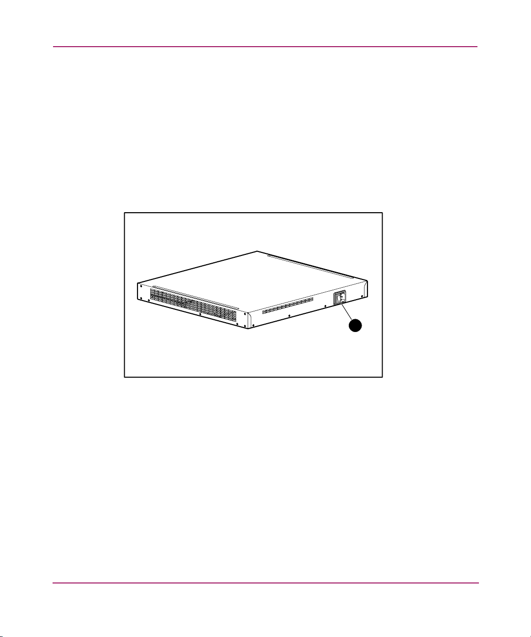
6 Rear panel, power connector . . . . . . . . . . . . . . . . . . . . . . . . . . . . . . . . . . . . . . . . . . . . . . 26
7 Installing cage nuts. . . . . . . . . . . . . . . . . . . . . . . . . . . . . . . . . . . . . . . . . . . . . . . . . . . . . . 30
8 Rail assembly . . . . . . . . . . . . . . . . . . . . . . . . . . . . . . . . . . . . . . . . . . . . . . . . . . . . . . . . . . 31
9 Removing the screws . . . . . . . . . . . . . . . . . . . . . . . . . . . . . . . . . . . . . . . . . . . . . . . . . . . . 31
10 Attaching the rails . . . . . . . . . . . . . . . . . . . . . . . . . . . . . . . . . . . . . . . . . . . . . . . . . . . . . . 32
11 Installing the storage router into the rack. . . . . . . . . . . . . . . . . . . . . . . . . . . . . . . . . . . . . 32
12 Securing the rear of the rails . . . . . . . . . . . . . . . . . . . . . . . . . . . . . . . . . . . . . . . . . . . . . . 33
13 MT-RJ fiber-optic connector and SFP module . . . . . . . . . . . . . . . . . . . . . . . . . . . . . . . . 34
14 LC connector and fiber-optic SFP module. . . . . . . . . . . . . . . . . . . . . . . . . . . . . . . . . . . . 35
15 Mylar tab SFP module . . . . . . . . . . . . . . . . . . . . . . . . . . . . . . . . . . . . . . . . . . . . . . . . . . . 36
10 IP Storage Router SR2122-2 User Guide
Page 11

Contents
16 Inserting a Mylar tab SFP module . . . . . . . . . . . . . . . . . . . . . . . . . . . . . . . . . . . . . . . . . . 36
17 Removing a Mylar tab SFP module. . . . . . . . . . . . . . . . . . . . . . . . . . . . . . . . . . . . . . . . . 37
18 Actuator/button SFP module . . . . . . . . . . . . . . . . . . . . . . . . . . . . . . . . . . . . . . . . . . . . . . 38
19 Inserting an actuator/button SFP module. . . . . . . . . . . . . . . . . . . . . . . . . . . . . . . . . . . . . 38
20 Removing an actuator/button SFP module from a port . . . . . . . . . . . . . . . . . . . . . . . . . . 39
21 Bale clasp SFP module. . . . . . . . . . . . . . . . . . . . . . . . . . . . . . . . . . . . . . . . . . . . . . . . . . . 40
22 Inserting a bale clasp SFP module into a port . . . . . . . . . . . . . . . . . . . . . . . . . . . . . . . . . 40
23 Removing a bale clasp SFP module with a flat-blade screwdriver . . . . . . . . . . . . . . . . . 41
24 Removing a bale clasp SFP module from a port . . . . . . . . . . . . . . . . . . . . . . . . . . . . . . . 41
25 Connecting to the 10/100 management and HA ports . . . . . . . . . . . . . . . . . . . . . . . . . . . 44
26 Connecting the console cable. . . . . . . . . . . . . . . . . . . . . . . . . . . . . . . . . . . . . . . . . . . . . . 45
27 Power set to Off . . . . . . . . . . . . . . . . . . . . . . . . . . . . . . . . . . . . . . . . . . . . . . . . . . . . . . . . 46
28 Connecting a power cord to the power connector . . . . . . . . . . . . . . . . . . . . . . . . . . . . . . 46
29 SCSI routing. . . . . . . . . . . . . . . . . . . . . . . . . . . . . . . . . . . . . . . . . . . . . . . . . . . . . . . . . . . 58
30 FCIP . . . . . . . . . . . . . . . . . . . . . . . . . . . . . . . . . . . . . . . . . . . . . . . . . . . . . . . . . . . . . . . . . 59
31 SCSI routing overview. . . . . . . . . . . . . . . . . . . . . . . . . . . . . . . . . . . . . . . . . . . . . . . . . . . 61
32 Routing SCSI requests and responses for SCSI routing . . . . . . . . . . . . . . . . . . . . . . . . . 62
33 SCSI routing actions . . . . . . . . . . . . . . . . . . . . . . . . . . . . . . . . . . . . . . . . . . . . . . . . . . . . 63
34 SCSI Routing basic network structure . . . . . . . . . . . . . . . . . . . . . . . . . . . . . . . . . . . . . . . 64
35 SCSI routing storage mapping and access control concept . . . . . . . . . . . . . . . . . . . . . . . 67
36 FCIP Overview. . . . . . . . . . . . . . . . . . . . . . . . . . . . . . . . . . . . . . . . . . . . . . . . . . . . . . . . . 69
37 FCIP actions. . . . . . . . . . . . . . . . . . . . . . . . . . . . . . . . . . . . . . . . . . . . . . . . . . . . . . . . . . . 70
38 FCIP redundant WAN configuration . . . . . . . . . . . . . . . . . . . . . . . . . . . . . . . . . . . . . . . . 71
39 FCIP fully redundant configuration . . . . . . . . . . . . . . . . . . . . . . . . . . . . . . . . . . . . . . . . . 72
40 Multisite FCIP configuration . . . . . . . . . . . . . . . . . . . . . . . . . . . . . . . . . . . . . . . . . . . . . . 73
41 Mixed mode overview (SCSI routing and FCIP). . . . . . . . . . . . . . . . . . . . . . . . . . . . . . . 74
42 VLAN access overview . . . . . . . . . . . . . . . . . . . . . . . . . . . . . . . . . . . . . . . . . . . . . . . . . . 76
43 Storage router interface naming system. . . . . . . . . . . . . . . . . . . . . . . . . . . . . . . . . . . . . . 80
44 Storage router chassis-slot numbering . . . . . . . . . . . . . . . . . . . . . . . . . . . . . . . . . . . . . . . 80
45 System parameters example configuration . . . . . . . . . . . . . . . . . . . . . . . . . . . . . . . . . . . 99
46 Contrast of configuring for VLAN with VTP and without VTP . . . . . . . . . . . . . . . . . . 113
47 Configuration elements for SCSI routing . . . . . . . . . . . . . . . . . . . . . . . . . . . . . . . . . . . 122
48 SCSI routing parameters example configuration . . . . . . . . . . . . . . . . . . . . . . . . . . . . . . 123
49 Configuration of SCSI routing determines VLAN access to storage . . . . . . . . . . . . . . 124
50 iSCSI authentication configuration elements. . . . . . . . . . . . . . . . . . . . . . . . . . . . . . . . . 148
51 iSCSI authentication example configuration . . . . . . . . . . . . . . . . . . . . . . . . . . . . . . . . . 149
52 Straight-through cables . . . . . . . . . . . . . . . . . . . . . . . . . . . . . . . . . . . . . . . . . . . . . . . . . 212
53 Cross-connect cables . . . . . . . . . . . . . . . . . . . . . . . . . . . . . . . . . . . . . . . . . . . . . . . . . . . 213
11IP Storage Router SR2122-2 User Guide
Page 12

Contents
54 Rollover cable for connection to console port . . . . . . . . . . . . . . . . . . . . . . . . . . . . . . . . 214
55 FCIP only . . . . . . . . . . . . . . . . . . . . . . . . . . . . . . . . . . . . . . . . . . . . . . . . . . . . . . . . . . . . 228
56 FCIP with local iSCSI hosts. . . . . . . . . . . . . . . . . . . . . . . . . . . . . . . . . . . . . . . . . . . . . . 229
57 FCIP with remote iSCSI hosts . . . . . . . . . . . . . . . . . . . . . . . . . . . . . . . . . . . . . . . . . . . . 230
Tables
1 Document Conventions . . . . . . . . . . . . . . . . . . . . . . . . . . . . . . . . . . . . . . . . . . . . . . . . . . 15
2 Front panel LED descriptions . . . . . . . . . . . . . . . . . . . . . . . . . . . . . . . . . . . . . . . . . . . . . 24
3 Types of SFP Modules for Gigabit Ethernet and Fibre Channel ports . . . . . . . . . . . . . . 35
4 Console port default characteristics . . . . . . . . . . . . . . . . . . . . . . . . . . . . . . . . . . . . . . . . . 45
5 Target and LUN Mapping Example. . . . . . . . . . . . . . . . . . . . . . . . . . . . . . . . . . . . . . . . . 65
6 Target-only Mapping Example . . . . . . . . . . . . . . . . . . . . . . . . . . . . . . . . . . . . . . . . . . . . 65
7 SCSI Routing Storage Mapping and Access Control Concept . . . . . . . . . . . . . . . . . . . . 68
8 Interface Type Designators . . . . . . . . . . . . . . . . . . . . . . . . . . . . . . . . . . . . . . . . . . . . . . . 80
9 Collecting Configuration Information . . . . . . . . . . . . . . . . . . . . . . . . . . . . . . . . . . . . . . . 83
10 Storage Router First-Time Configuration Checklist . . . . . . . . . . . . . . . . . . . . . . . . . . . . 86
11 Terminal Emulation Configuration . . . . . . . . . . . . . . . . . . . . . . . . . . . . . . . . . . . . . . . . . 87
12 Configuration items in Initial System Configuration Script . . . . . . . . . . . . . . . . . . . . . . 88
13 Special Keys. . . . . . . . . . . . . . . . . . . . . . . . . . . . . . . . . . . . . . . . . . . . . . . . . . . . . . . . . . . 93
14 Logging into the Web-Based GUI . . . . . . . . . . . . . . . . . . . . . . . . . . . . . . . . . . . . . . . . . . 94
15 Menu and Item Links . . . . . . . . . . . . . . . . . . . . . . . . . . . . . . . . . . . . . . . . . . . . . . . . . . . . 95
16 Optional Operational Parameters: TCP Protocol . . . . . . . . . . . . . . . . . . . . . . . . . . . . . . 141
17 Event Message Notification Levels . . . . . . . . . . . . . . . . . . . . . . . . . . . . . . . . . . . . . . . . 205
18 Event Message Logging Destinations . . . . . . . . . . . . . . . . . . . . . . . . . . . . . . . . . . . . . . 205
19 Event Massage Facilities . . . . . . . . . . . . . . . . . . . . . . . . . . . . . . . . . . . . . . . . . . . . . . . . 206
20 Storage Router Specifications . . . . . . . . . . . . . . . . . . . . . . . . . . . . . . . . . . . . . . . . . . . . 210
21 SFP Modules and Connectors . . . . . . . . . . . . . . . . . . . . . . . . . . . . . . . . . . . . . . . . . . . . 212
22 10/100 Ethernet Management and HA Port Pinouts . . . . . . . . . . . . . . . . . . . . . . . . . . . 213
23 Console Port Pinouts . . . . . . . . . . . . . . . . . . . . . . . . . . . . . . . . . . . . . . . . . . . . . . . . . . . 215
24 Laser Information. . . . . . . . . . . . . . . . . . . . . . . . . . . . . . . . . . . . . . . . . . . . . . . . . . . . . . 223
12 IP Storage Router SR2122-2 User Guide
Page 13

About This
Guide
This user guide provides information to help you:
■ Install the SR2122-2 IP Storage Router
■ Configure the SR2122-2 IP Storage Router
About this Guide
About this Guide
“About this Guide” topics include:
■ “Overview” on page 14
■ “Conventions” on page 15
■ “Rack Stability” on page 17
■ “Getting Help” on page 18
13IP Storage Router SR2122-2 User Guide
Page 14

About This Guide
Overview
This section covers the following topics:
■ Intended Audience
■ Prerequisites
■ Related Documentation
Intended Audience
This book is intended for use by system administrators and technicians who are
experienced with the following:
■ Hardware installation and configuration.
■ Ethernet and Fibre Channel Storage networks.
Prerequisites
Before you configure the storage router, make sure you review the following
chapters and collect the information specified in Chapter 5.
■ Chapter 4, Software Overview
■ Chapter 5, Configuring the Storage Router
Related Documentation
In addition to this guide, HP provides corresponding information:
■ StorageWorks IP Storage Router 2122-2 Command Line Interface Reference
Guide
■ StorageWorks IP Storage Router 2122-2 Release Notes
14 IP Storage Router SR2122-2 User Guide
Page 15
Conventions
Conventions consist of the following:
■ Document Conventions
■ Text Symb ols
■ Equipment Symbols
Document Conventions
The document conventions included in Table 1 apply in most cases.
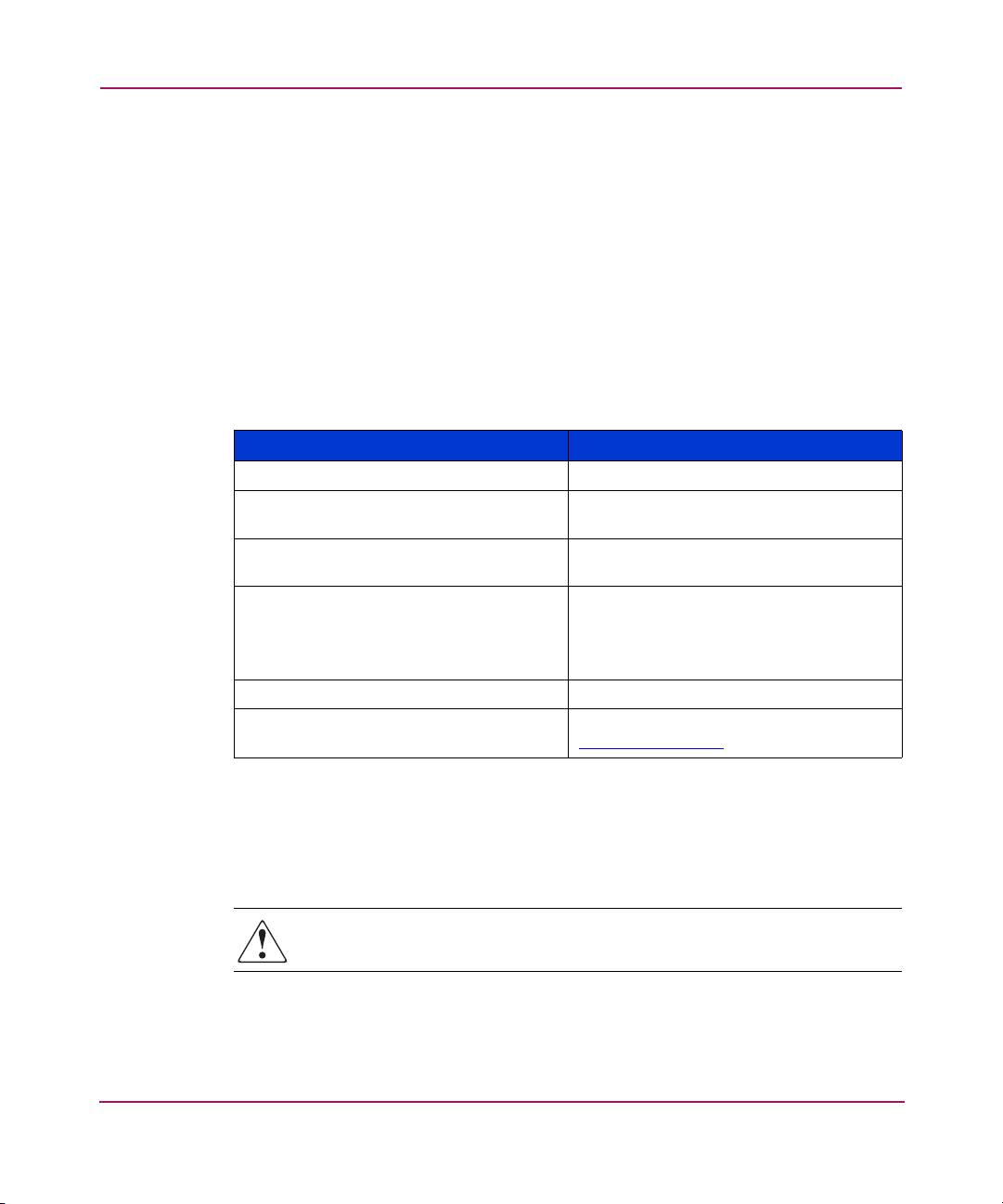
Table 1: Document Conventions
Cross-reference links Blue text: Figure 1
Key and field names, menu items,
buttons, and dialog box titles
File names, application names, and text
emphasis
User input, command and directory
names, and system responses (output
and messages)
Variables <monospace, italic font>
Website addresses Blue, underlined sans serif font text:
About This Guide
Element Convention
Bold
Italics
Monospace font
COMMAND NAMES are uppercase
monospace font unless they are case
sensitive
http://www.hp.com
Text Symbols
The following symbols may be found in the text of this guide. They have the
following meanings:
WARNING: Text set off in this manner indicates that failure to follow
directions in the warning could result in bodily harm or death.
IP Storage Router SR2122-2 User Guide
15
Page 16
About This Guide
Caution: Text set off in this manner indicates that failure to follow directions
could result in damage to equipment or data.
Note: Text set off in this manner presents commentary, sidelights, or interesting points
of information.
Equipment Symbols
The following equipment symbols may be found on hardware for which this guide
pertains. They have the following meanings:
Any enclosed surface or area of the equipment marked with these
symbols indicates the presence of electrical shock hazards. Enclosed
area contains no operator serviceable parts.
WARNING: To reduce the risk of personal injury from electrical shock
hazards, do not open this enclosure.
Any RJ-45 receptacle marked with these symbols indicates a network
interface connection.
WARNING: To reduce the risk of electrical shock, fire, or damage to the
equipment, do not plug telephone or telecommunications connectors
into this receptacle.
Any surface or area of the equipment marked with these symbols
indicates the presence of a hot surface or hot component. Contact with
this surface could result in injury.
WARNING: To reduce the risk of personal injury from a hot component,
allow the surface to cool before touching.
16 IP Storage Router SR2122-2 User Guide
Page 17
Rack Stability
Rack stability protects personnel and equipment.
About This Guide
Power supplies or systems marked with these symbols indicate the
presence of multiple sources of power.
WARNING: To reduce the risk of personal injury from electrical
shock, remove all power cords to completely disconnect power
from the power supplies and systems.
Any product or assembly marked with these symbols indicates that the
component exceeds the recommended weight for one individual to
handle safely.
WARNING: To reduce the risk of personal injury or damage to the
equipment, observe local occupational health and safety requirements
and guidelines for manually handling material.
WARNING: To reduce the risk of personal injury or damage to the
equipment, be sure that:
■ The leveling jacks are extended to the floor.
■ The full weight of the rack rests on the leveling jacks.
■ In single rack installations, the stabilizing feet are attached to the rack.
■ In multiple rack installations, the racks are coupled.
■ Only one rack component is extended at any time. A rack may become
unstable if more than one rack component is extended for any reason.
IP Storage Router SR2122-2 User Guide
17
Page 18

About This Guide
Getting Help
If you still have a question after reading this guide, contact an HP authorized
service provider or access our website:
HP Technical Support
Telephone numbers for worldwide technical support are listed on the following
HP website:
of origin.
Note: For continuous quality improvement, calls may be recorded or monitored.
Be sure to have the following information available before calling:
■ Technical support registration number (if applicable)
■ Product serial numbers
■ Product model names and numbers
■ Applicable error messages
http://www.hp.com
http:// www.hp.com/support/
.
. From this website, select the country
■ Operating system type and revision level
■ Detailed, specific questions
HP Storage Website
The HP website has the latest information on this product, as well as the latest
drivers. Access storage at:
storage.html
. From this website, select the appropriate product or solution.
http://www.hp .com/country/us/eng/p rodserv/
HP Authorized Reseller
For the name of your nearest HP authorized reseller:
■ In the United States, call 1-800-345-1518
■ In Canada, call 1-800-263-5868
■ Elsewhere, see the HP website for locations and telephone numbers:
http:// www.hp.com
18 IP Storage Router SR2122-2 User Guide
.
Page 19

Product Overview
This chapter is the starting point for installing the IP Storage Router 2122-2
hardware. It provides some very basic information you should know before
proceeding to other chapters in this manual, and contains the following topics:
■ Basic Description
■ Port Descriptions
■ Front-Panel LEDs
■ Fan Assembly
■ Power Supply
Installing and configuring a SR2122-2 storage router consists of the following
tasks:
■ Installing the storage router
■ Configuring the storage router software
■ Installing and configure the iSCSI drivers
1
19IP Storage Router SR2122-2 User Guide
Page 20

Product Overview
Basic Description
The ST2122-2 is a 1U, rack-mountable storage router that provides IP hosts
access to Fibre Channel storage through an IP network.
Figure 1: Storage router chassis
The SR2122-2 provides access to Fibre Channel storage as if the IP hosts were
directly attached to the storage. For more information about the types of storage
access available with the storage router, see Chapter 4, “Software Overview” and
other related documentation.
hp StorageWorks IP storage router 2122-2
15001
IP hosts
hp SR2122-2
IP
An IP host accesses
FC storage as if it
were directly attached
to the storage.
FC storage
15002
Figure 2: IP hosts accessing storage through the storage router
20 IP Storage Router SR2122-2 User Guide
Page 21
Port Descriptions
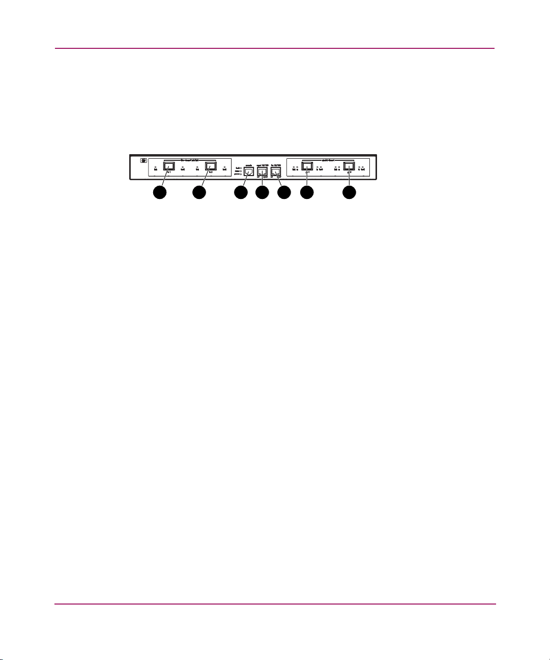
The SR2122-2 provides two 1-Gigabit Ethernet ports, a console port, a 10/100
Ethernet management port, a 10/100 Ethernet high availability (HA) port, and two
1-Gigabit/2-Gigabit Fibre Channel ports.
1 2 4 5 6 73
Figure 3: Storage router ports
Product Overview
hp StorageWorks IP storage router 2122-2
15003
1 Fibre Channel 1G/2G, FC 1
2 Fibre Channel 1G/2G, FC 2
3 Console port, CONSOLE
4 10/100 Ethernet management port,
MGMT 10/100
The following sections describe the ports:
■ Gigabit Ethernet Ports
■ Console Port
■ 10/100 Ethernet Management Port
■ 10/100 Ethernet HA Port
■ Fibre Channel Ports
Gigabit Ethernet Ports
The Gigabit Ethernet ports are labeled GE 1 and GE 2 (see Figure 3). Each port
provides a 1-Gigabit Ethernet interface for connecting to IP hosts that require
access to storage. Each port uses a small form-factor pluggable (SFP) module for
connection to the port’s physical medium. See Appendix B, “Cable and Port
Pinouts” for SFP module specifications. Each Gigabit Ethernet port has LEDs
indicating its status, as described in Front-Panel LEDs, page 23.
5 10/100 Ethernet high availability (HA)
port, HA 10/100
6 Gigabit Ethernet, GE 1
7 Gigabit Ethernet, GE 2
21IP Storage Router SR2122-2 User Guide
Page 22

Product Overview
Console Port
The console port is labeled CONSOLE (see Figure 3). It is an EIA/TIA-232
interface for connecting to the serial port of a PC running terminal emulation
software. Using the console port, you can manage the storage router with the
storage router command line interface (CLI). The console port uses an 8-pin
RJ-45 receptacle; it has no LEDs.
Caution: The console cable may be connected to the unit during installation
and maintenance only. The console cable must be disconnected from the unit
when not in use during normal operation to minimize the electromagnetic
interference.
10/100 Ethernet Management Port
The 10/100 Ethernet management port is labeled MGMT 10/100 (see Figure 3). It
is a 10BaseT/100BaseT Ethernet interface for connecting to a management
network. Through a management network, you can manage the storage router
using the CLI, the web-based GUI, or SNMP. The 10/100 Ethernet management
port uses an 8-pin RJ-45 receptacle and has LEDs indicating its status, as
described in “Front-Panel LEDs” on page 23.
10/100 Ethernet HA Port
The 10/100 Ethernet high-availability (HA) port is labeled HA 10/100 (see
Figure 3). It is a 10BaseT/100BaseT Ethernet interface for connecting to an HA
network. The port allows the storage router to function in a multiple-node cluster
with other storage routers to provide fault-tolerant operation. The 10/100 Ethernet
HA port uses an 8-pin RJ-45 receptacle and has LEDs indicating its status, as
described in “Front-Panel LEDs” on page 23.
Fibre Channel Ports
The Fibre Channel ports are labeled FC 1 and FC 2 (see Figure 3). Each port
provides a 1-Gigabit/2-Gigabit Fibre Channel interface for connecting to storage
systems, Fibre Channel switches, Fibre Channel hosts, or other HP storage
networking products. Each Fibre Channel port can be configured as one of the
following port types: G_Port, GL_Port, F_Port, FL_Port, or TL_Port. Each port
uses a small form-factor pluggable (SFP) module for connection to the port’s
22 IP Storage Router SR2122-2 User Guide
Page 23

physical medium. See Chapter B, “Cable and Port Pinouts” for SFP module
specifications. Each Fibre Channel port has LEDs indicating its status, as
described in the “Front Panel LEDs” section that follows.
Front-Panel LEDs
The front-panel LEDs provide status indications about the storage router chassis
and its ports (see Figure 4).
■ Each Gigabit Ethernet port, GE 1 and GE 2, has four LEDs, labeled LINK,
RX, TX, and FAULT. The LEDs are located to the left and right of each
Gigabit Ethernet port.
■ The FAULT, STATUS, and POWER LEDs indicate the overall status of the
storage router. The LEDs are located to the left of the CONSOLE port.
■ The 10/100 Ethernet management port, MGMT 10/100, has two LEDs,
labeled ACT and SPEED. The ACT LED is located at the left-bottom corner
of the port; the SPEED LED is located at the right-bottom corner of the port.
■ The 10/100 Ethernet HA port, HA 10/100, has two LEDs, labeled ACT and
SPEED. The ACT LED is located at the left-bottom corner of the port; the
SPEED LED is located at the right-bottom corner of the port.
Product Overview
■ Each Fibre Channel port has two LEDs, labeled LINK and FAULT. The LEDs
are located to the left and right of each Fibre Channel port.
hp StorageWorks IP storage router 2122-2
1 2 4 5 6 7 8 93
15004
Figure 4: Front panel LEDs
1 FC 1 LINK
2 FC 1 FAULT
3 FC 2 LINK
4 FC 2 FAULT
5 FAULT, STATUS, POWER
6 GE 1 LINK and RX
7 GE 1 TX and FAULT
8 GE 2 LINK AND RX
9 GE 2 TX and FAULT
23IP Storage Router SR2122-2 User Guide
Page 24

Product Overview
Table 2: Front panel LED descriptions
LED Color Description
GE 1
and
GE 2
LEDs
LINK Green Port is operational
TX Green Packets are being transmitted
RX Green Packets are being received
FAULT Red On — Error in Storage Router
Flashing — Error in a storage router
component
Status Green On — Successful boot up
Flashing — Booting up
POWER Green Power is on
MGMT
10/100
LEDs
HA
10/100
LEDs
FC 1
and FC
2 LEDs
ACT Green Link is active
SPEED Yellow Port speed is 100 Mbps
ACT Green Link is active
SPEED Yellow Port speed is 100 Mbps
ACT Yellow Frames are being transmitted or received
LOG Green On — Port is properly connected
Flashing once per second — Port is
logging in
Flashing twice per second — Port
connection error
24 IP Storage Router SR2122-2 User Guide
Page 25
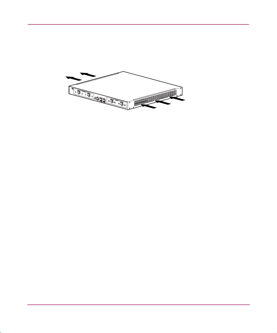
Fan Assembly
The fan assembly provides cooling for the internal chassis components. The
storage router chassis contains four exhaust fans that are located on the left side of
the chassis. The fans draw air in from the right and exhaust it out through the left.
Figure 5: Chassis airflow
Product Overview
hp StorageWorks IP storage router 2122-2
15005
25IP Storage Router SR2122-2 User Guide
Page 26
Product Overview
Power Supply
The SR2122-2 has an internal power supply that monitors its temperature and
output voltages. The power supply automatically senses and adjusts to either of
these input voltages: 115 VAC/60 Hz or 230 VAC/50 Hz.
If conditions reach critical thresholds, the power supply shuts down to avoid
damage from excessive heat or electrical current. The power supply connects to
site power through a power cord and the power connector on the rear panel. The
power supply is powered on with a rocker switch next to the power connector. The
switch is labeled
off.
I
and O. Pressing I switches power on. Pressing O switches power
1
Figure 6: Rear panel, power connector
1 Power Connector
26 IP Storage Router SR2122-2 User Guide
Page 27

Installation
This chapter describes how to:
■ Prepare your site for installation
■ Prepare and install the SR2122-2 storage router
■ Connect network and Fibre Channel cables
■ Connect power
■ Verify correct installation
For first-time installations, perform the procedures in the following sections in the
order listed here:
■ Site Planning
■ Installing the Storage Router
■ Installing SFP Modules
■ Connecting to Gigabit Ethernet and Fibre Channel Ports
■ Connecting to the 10/100 Ethernet Management and HA Ports
2
■ Connecting to the Console Port
■ Connecting Power
■ Verifying Installation
■ Where to Go Next
27IP Storage Router SR2122-2 User Guide
Page 28

Installation
Site Planning
Planning the proper location and layout of your SR2122-2, your equipment rack,
or wiring closet is essential for successful storage router operation. Equipment
placed too close together or in a poorly ventilated area can cause the system to
overheat. In addition, poor equipment placement can make system panels
inaccessible and difficult to maintain.
Table 20 in Appendix A lists the operating and nonoperating environmental site
requirements for the SR2122-2. Within specified environmental ranges, the
system can continue to operate; however, a measurement that approaches the
minimum or maximum of a range indicates a potential problem. You can maintain
normal operation by anticipating and correcting environmental conditions before
they exceed the maximum operating range.
Verify the site power for the type of device you are installing. Power requirements
are useful for planning the power distribution system needed to support the
storage router. Heat dissipation is an important consideration for sizing the
air-conditioning requirements for an installation. See Tabl e 20 in Appendix A for
power and heat ratings for the SR2122-2.
Caution: To prevent a loss of input power, verify that the total maximum load
on the circuit supplying power to the power supply is within the current ratings
of the wiring and breakers.
Installing the Storage Router
You can install the SR2122-2 on a table or a shelf, or in an equipment rack. The
following sections describe the steps required to install the storage router:
■ Installing on a Table or a Shelf
■ Rack-Mounting the Storage Router
■ Installing SFP Modules
28 IP Storage Router SR2122-2 User Guide
Page 29

Installing on a Table or a Shelf
You can install the storage router on a table or a shelf (or another flat, secure
surface).
If you are going to install the storage router in an equipment rack, skip this section
and proceed to the “Rack-Mounting the Storage Router” section. To install the
chassis on a table or a shelf:
1. Locate the four adhesive-backed rubber feet in the accessory kit that is
shipped with the storage router.
2. Peel the rubber feet from their backing and place the feet onto the four round
recessed areas on the bottom of the chassis.
3. Place the storage router on a table or a shelf near an AC power source.
Rack-Mounting the Storage Router
You can rack-mount the SR2122-2 in a 19-inch equipment rack with the front
panel forward.
The accessory kit shipped with your storage router contains:
■ two rails
Installation
■ two wing nuts
■ various screws
You need the following tools to install the SR2122-2 in a rack:
■ Phillips screwdriver
■ Tape mea s ure
To install the SR2122-2 in a rack:
1. Prepare for installation:
a. Place the storage router on the floor or on a sturdy table as close as
possible to the rack. Leave enough clearance so that you can move around
the storage router.
b. Use a tape measure to measure the depth of the rack. Measure from the
outside of the front mounting uprights to the outside of the rear mounting
uprights. The depth must be at least 19 inches (48.26 cm) but not more
than 32 inches (81.3 cm).
29IP Storage Router SR2122-2 User Guide
Page 30

Installation
c. Measure the space between the inner edges of the left-front and
right-front mounting uprights to ensure that the space is 17.75 inches
(45.72 cm) wide.
2. Use the rack template provided to mark the center of a 1U mounting location
on both sides of the front and rear mounting uprights.
3. Install cage nuts in the locations marked in step 2.
Figure 7: Installing cage nuts
4. Assemble the rails using the supplied wing nuts (see Figure 8).
Note: Do not tighten the wing nuts completely because the rails will need to be
adjusted later in the installation process.
30 IP Storage Router SR2122-2 User Guide
Page 31

Figure 8: Rail assembly
5. Remove three existing screws from each side of the chassis (6 total).
Installation
Figure 9: Removing the screws
hp StorageWorks IP storage router 2122-2
15006
31IP Storage Router SR2122-2 User Guide
Page 32

Installation
6. Align and attach the rails to the chassis using the supplied flat-head screws.
hp StorageWorks IP storage router 2122-2
15007
Figure 10: Attaching the rails
7. Slide the storage router into the rack and secure the front of the rails using the
rack screws.
hp StorageWorks IP storage router 2122-2
15008
Figure 11: Installing the storage router into the rack
8. Adjust and secure the rear of the rails using the rack screws (see
Figure 12).
9. Secure
32 IP Storage Router SR2122-2 User Guide
the rail halves by tightening the wing nuts.
Page 33

Figure 12: Securing the rear of the rails
Installing SFP Modules
Before installing or removing an SFP (small form-factor pluggable) module, read
the installation information in this section. For connecting to SFP modules in the
Gigabit Ethernet ports and the Fibre Channel ports, read the instructions in the
“Connecting to Gigabit Ethernet and Fibre Channel Ports” section.
Installation
3
2
1
Note: Because of interoperability issues, HP does not support SFPs purchased from
third-party vendors. See Chapter B, “Cable and Port Pinouts” for SFP port
specifications.
Note: When fiber-optic cable plugs and SFP module receptacles are disconnected
from each other, place dust covers on them.
33IP Storage Router SR2122-2 User Guide
Page 34

Installation
WARNING: Because invisible radiation may be emitted from the aperture of
the port when no fiber cable is connected, avoid exposure to radiation and do
not stare into open apertures. To see translated versions of the warning, refer
to the Regulatory Compliance and Safety document that accompanied the
device.
The Gigabit Ethernet ports use fiber-optic SFP modules with either MT-RJ
connectors (see Figure 13) or LC connectors (see Figure 14). The Fibre Channel
ports use fiber-optic SFP modules with LC connectors (see Figure 14). Refer to
Table 3 to determine what types of SFP modules you can install in the Gigabit
Ethernet and Fibre Channel ports. See Appendix B, “Cable and Port Pinouts,” for
SFP module specifications.
MT-RJ plug
SFP module
Figure 13: MT-RJ fiber-optic connector and SFP module
Caution: Protect your fiber-optic SFP modules by inserting clean dust covers
into the SFPs after the cables are extracted from them. Be sure to clean the
optic surfaces of the fiber cables before you plug them back into the optical
bores of another SFP module. Avoid getting dust and other contaminants into
the optical bores of your SFP modules; the optics will not work correctly when
obstructed with dust.
34 IP Storage Router SR2122-2 User Guide
Page 35

LC plug
SFP module
Figure 14: LC connector and fiber-optic SFP module
Table 3: Types of SFP Modules for Gigabit Ethernet and Fibre Channel ports
SFP Option Kit Part
Number
Connector Type Port
221470-B21 LC Gigabit Ethernet or Fibre
Channel
Installation
The SFP modules have three different types of latching devices used to secure and
detach the SFP module from a port. The three types of SFP modules are described
in the following sections:
■ Mylar Tab SFP Modules
■ Actuator/Button SFP Modules
■ Bale Clasp SFP Modules
35IP Storage Router SR2122-2 User Guide
Page 36

Installation
Mylar Tab SFP Modules
The Mylar tab SFP module has a tab that must be pulled to remove the module
from a port.
Figure 15: Mylar tab SFP module
To insert the Mylar tab SFP module into a port, line up the SFP module with the
port, and slide it into place.
hp StorageWorks IP storage router 2122-2
15009
Figure 16: Inserting a Mylar tab SFP module
36 IP Storage Router SR2122-2 User Guide
Page 37

Installation
Caution: When pulling the tab to remove the SFP module, be sure to pull in a
straight outward motion. Do not twist or pull the tab, you may disconnect it
from the SFP module.
To remove the SFP module from the port, pull the tab gently in a downward
direction until it disengages from the port, and then pull the SFP module out.
hp StorageWorks IP storage router 2122-2
Figure 17: Removing a Mylar tab SFP module
15010
37IP Storage Router SR2122-2 User Guide
Page 38

Installation
Actuator/Button SFP Modules
The actuator/button SFP module has a button that must be pushed to remove the
SFP module from a port.
Figure 18: Actuator/button SFP module
To insert the actuator/button SFP module into a port, line up the SFP module with
the port and slide it in until the actuator/button clicks into place. Be sure not to
press the actuator/button as you insert the SFP module, you could inadvertently
disengage the SFP module from the port.
hp StorageWorks IP storage router 2122-2
15011
Figure 19: Inserting an actuator/button SFP module
38 IP Storage Router SR2122-2 User Guide
Page 39

To remove an actuator/button SFP module from a port:
Installation
1. Gently press the actuator/button
on the front of the SFP module until it
clicks and the latch mechanism releases the SFP module from the port.
2. Grasp the actuator/button between your thumb and index finger and carefully
pull the SFP module
hp StorageWorks IP storage router 2122-2
Figure 20: Removing an actuator/button SFP module from a port
from the port.
2
1
15012
39IP Storage Router SR2122-2 User Guide
Page 40

Installation
Bale Clasp SFP Modules
The bale clasp SFP module has a bale clasp used to secure the SFP module in a
port.
Figure 21: Bale clasp SFP module
To insert a bale clasp SFP module into a port:
1. Close the bale clasp before inserting the SFP module.
2. Line up the SFP module with the port and slide it into the port.
hp StorageWorks IP storage router 2122-2
1
Figure 22: Inserting a bale clasp SFP module into a port
40 IP Storage Router SR2122-2 User Guide
2
15013
Page 41

Installation
To remove a bale clasp SFP module from a port:
1. Open the bale clasp on the SFP module with your index finger, a small
flat-blade screwdriver, or other long narrow instrument in a downward
direction.
hp StorageWorks IP storage router 2122-2
1
2
15015
Figure 23: Removing a bale clasp SFP module with a flat-blade screwdriver
2. Grasp the SFP module between your thumb and index finger and carefully
remove it from the port.
hp StorageWorks IP storage router 2122-2
1
2
15014
Figure 24: Removing a bale clasp SFP module from a port
41IP Storage Router SR2122-2 User Guide
Page 42

Installation
Connecting to Gigabit Ethernet and Fibre Channel Ports
The Gigabit Ethernet ports, GE 1 and GE 2, use MT-RJ-type or LC-type
fiber-optic SFP modules and cables. The Fibre Channel ports, FC 1 and FC 2, use
LC-type fiber-optic SFP modules and cables. When connecting a cable to a
fiber-optic SFP module, make sure that you firmly press the cable plug into the
socket. The upper edge of the plug must snap into the upper front edge of the
socket and you should hear the plug click when it is locked into the socket. To
make sure that the plug is locked into the socket, gently pull on it.
To disconnect a plug from a socket, press the trigger on top of the plug, releasing
the latch. You should hear a click, which indicates that the latch has released.
Carefully pull the plug out of the socket.
Note: When you disconnect the fiber-optic cable from the module, grip the body of the
connector. Do not grip the connector jacket-sleeve. Pulling on the sleeve can, over time,
compromise the integrity of the fiber-optic cable termination in the connector.
Dirt or skin oils may have accumulated on an MT-RJ plug faceplate (around the
optical-fiber openings), which can generate significant attenuation and reduce the
optical power levels below threshold levels so that a link cannot be made. To clean
an MT-RJ plug faceplate, follow this procedure:
1. Using a lint-free tissue soaked in 99 percent pure isopropyl alcohol, gently
wipe the faceplate.
2. Remove any residual dust from the faceplate with compressed air before
installing the cable.
Note: When fiber-optic cable plugs and SFP module receptacles are disconnected
from each other, place dust covers on them.
The following sections describe how to connect cables to the Gigabit Ethernet and
Fibre Channel ports:
■ Connecting to a Gigabit Ethernet Port
■ Connecting to a Fibre Channel Port
42 IP Storage Router SR2122-2 User Guide
Page 43

Connecting to a Gigabit Ethernet Port
To connect a cable to a Gigabit Ethernet port:
1. Remove the dust cover from the SFP module in the Gigabit Ethernet port;
store the dust cover for future use.
2. Remove the dust cover (or covers) from the plug on the cable; store the cover
(or covers) for future use. Insert the cable plug into the Gigabit Ethernet SFP
module.
3. Connect the other end of the cable to the external end system, switch, or
router.
Connecting to a Fibre Channel Port
To connect a cable to a Fibre Channel port:
1. Remove the dust cover from the SFP module in the Fibre Channel SFP port;
store the dust cover for future use.
2. Remove the dust covers from the cable plug on the fiber-optic cable; store the
dust covers for future use. Insert the cable plug into the Fibre Channel SFP
module.
Installation
3. Connect the other end of the cable to a Fibre Channel port of another system
(for example, a storage system, switch, host, or another storage router).
Connecting to the 10/100 Ethernet Management and HA Ports
To connect to the 10/100 management and HA ports:
1. Use modular, RJ-45, straight-through UTP cables to connect the 10/100
management and HA ports to end systems. Use modular, RJ-45 cross-connect
cables to connect to external switches and routers.
2. Connect the appropriate modular cables to the 10/100 management and HA
ports (see Figure 25).
43IP Storage Router SR2122-2 User Guide
Page 44

Installation
hp StorageWorks IP storage router 2122-2
To management
network equipment
Figure 25: Connecting to the 10/100 management and HA ports
3. Connect the other end of the cable to the external end system, switch, or
router.
Connecting to the Console Port
Connect a PC serial port to the console port for local administrative access to the
storage router. The PC must support VT100 terminal emulation. The
terminal-emulation software — frequently a PC application such as
HyperTerminal or Procomm Plus — makes communication between the storage
router and your PC possible during setup and configuration.
Caution: The console cable may be connected to the unit during installation
and maintenance only. The console cable must be disconnected from the unit
when not in use during normal operation to minimize the electromagnetic
interference.
To HA network
equipment
15016
44 IP Storage Router SR2122-2 User Guide
Page 45

Installation
To connect to the console port:
1. Configure the PC terminal emulation program to match these console port
default characteristics:
Table 4: Console port default characteristics
Console Port Default Characteristics
Bits Per Second 9600
Data Bits 8
Parity None
Stop Bits 1
Flow Control None
2. Connect the supplied RJ-45-to-DB-9 female adapter to the PC serial port.
3. Connect one end of the supplied console cable (a rollover RJ-45-to-RJ-45
cable) to the console port. Connect the other end to the RJ-45-to-DB-9 adapter
at the PC serial port.
hp StorageWorks IP storage router 2122-2
Rollover cable
To PC
serial port
RJ-45/DB-9
adapter
Figure 26: Connecting the console cable
15017
45IP Storage Router SR2122-2 User Guide
Page 46

Installation
Connecting Power
The SR2122-2 can be connected to either of two power sources: 115-120 VAC/60
Hz or 230-240 VAC/50 Hz. The power supply automatically senses the source and
adjusts to either source.
To connect power to the storage router:
1. Make sure the power switch is set to Off.
Figure 27: Power set to Off
2. Plug the power cord into the power receptacle located on the rear panel in the
chassis.
Figure 28: Connecting a power cord to the power connector
3. Connect the other end of the power cord to the power source for the storage
router.
46 IP Storage Router SR2122-2 User Guide
Page 47

Verifying Installation
Verifying installation of the storage router consists of making sure that it starts
properly and that the network and Fibre Channel connections are operational.
Verifying Startup Operations
To verify that the storage router starts up properly:
1. At the rear of the SR2122-2, press the power switch to the on position.
2. At the front of the SR2122-2, observe the POWER LED to make sure power
is on. Make sure that the FAULT LED is off.
3. Listen and check for air flow to make sure the fan assembly is operating.
4. Observe console output to make sure that the storage router software is
booting properly. The boot process may last for three to five minutes and will
display boot information and a banner. A successful boot up is indicated by a
CLI prompt for user input.
5. If any of these conditions are not met, refer to Chapter 3, “Troubleshooting”
to isolate and, if possible, resolve the problem.
Installation
Verify that Network Connections are Operational
Verifying the network connections consists of making sure that the following
ports are operational: Gigabit Ethernet, 10/100 Ethernet management, and 10/100
HA.
To verify that the network connections are operational:
1. Verify the Gigabit Ethernet port connections by checking the port link status
LED. See Table 2 on page 24 for LED indication descriptions.
2. Verify the 10/100 Ethernet management port connection by checking the port
link status LED. See Table 2 on page 24 for LED indication descriptions.
3. Verify the 10/100 HA port connection by checking the port link status LED.
See Tab le 2 on page 24 for LED indication descriptions.
4. If any of these conditions are not met, see Chapter 3, “Troubleshooting” to
isolate and resolve the problem if possible.
47IP Storage Router SR2122-2 User Guide
Page 48

Installation
Verify That Fibre Channel Connections are Operational
To verify that the connections are operational:
1. Verify Fibre Channel port connections by checking Fibre Channel LOG
LEDs. See Table 2 on page page 24 for LED indication descriptions.
2. If the LOG LEDs for connected ports are flashing, see Chapter 3,
“Troubleshooting” to isolate and, if possible, resolve the problem.
Where to Go Next
Once you have verified that the storage router hardware is properly installed, it is
ready for software configuration. To configure the software, refer to Chapter 4,
“Software Overview”
48 IP Storage Router SR2122-2 User Guide
Page 49

Troubleshooting
This chapter provides troubleshooting procedures for problems encountered
during installation of the SR2122-2 Storage Router and consists of the following
sections:
■ Solving Problems at the Component Level
■ Identifying Startup Problems
■ Troubleshooting the Power Supply
■ Troubleshooting a Network or Fibre Channel Port Connection
■ Contacting Customer Service
3
49IP Storage Router SR2122-2 User Guide
Page 50

Troubleshooting
Solving Problems at the Component Level
The key to troubleshooting the SR2122-2 is to isolate the problem on a specific
storage router component. The first step is comparing what the storage router is
doing to what it should be doing. Because a startup problem is usually attributed
to a single component, it is more efficient to isolate the problem to a subsystem
rather than troubleshoot each separate component in the storage router.
The SR2122-2 consists of the following subsystems:
■ The power supply operates whenever system power is on (see
“Troubleshooting the Power Supply” on page 52.
■ The chassis fan assembly operates when the system power is on. The fan may
continue to operate even when the power supply shuts down the storage router
because of an over temperature or over voltage condition. The fan does not
operate if the power switch is off.
The following are simple checks you can make to determine if there is a fan
problem:
— Listen to the fan assembly to determine if it is operating.
— Check for any obstructions restricting airflow through the storage router.
If you determine that the fan assembly is not operating properly, contact a
customer service representative.
50 IP Storage Router SR2122-2 User Guide
Page 51

Identifying Startup Problems
Observe the operation of the SR2122-2 and its front-panel LEDs to determine
startup problems. LEDs indicate storage router status in the startup sequence. By
checking the LEDs, you can determine when and where the storage router failed
in the startup sequence.
To power up the storage router:
1. Listen for the chassis fan assembly operation. If it does not operate, see
“Troubleshooting the Power Supply” on page 52. If you determine that the
power supply is functioning normally and that the fan assembly is faulty,
contact a customer service representative. If the fan assembly does not
function properly at initial startup contact a customer service representative.
There are no installation adjustments that you can make.
2. Check the POWER LED on the front panel. The POWER LED turns on
immediately when power is on. The LED remains on during normal storage
router operation. If the LED is not on, see “Troubleshooting the Power
Supply” on page 52.
3. Check the STATUS and FAULT LEDs on the front panel. See “Front-Panel
LEDs” on page 23 for LED descriptions.
4. Check the network and Fibre Channel port LEDs on the front panel. See the
“Front-Panel LEDs” on page 23 for LED descriptions. If a network or Fibre
Channel port LED indicates a problem with the port connection, see
“Troubleshooting a Network or Fibre Channel Port Connection” on page 53.
Troubleshooting
5. Verify that the PC terminal emulation program is set correctly and that the PC
is connected properly to the console port. Also, verify at the PC terminal
emulation program display that the storage router has started up properly (for
example, a prompt for starting a configuration wizard or a CLI prompt).
6. Contact a customer service representative for instructions if a status LED
indicates a failure or if the PC connected to the console port indicates an
incomplete boot-up process.
51IP Storage Router SR2122-2 User Guide
Page 52

Troubleshooting
Troubleshooting the Power Supply
To help isolate a power problem:
1. Check the POWER LED.
■ If the POWER LED is off, verify that the power switch is in the on
position.
■ If the power switch is on, unplug the power cord and then plug the power
cord back in.
■ If the POWER LED remains off, continue with the next step.
2. Connect the power cord to another power source if one is available.
■ If the POWER LED comes on, the problem is the first power source.
■ If the POWER LED is off after you connect the power supply to a new
power source, replace the power cord.
■ If the POWER LED still fails to light when the storage router is connected
to a different power source with a new power cord, the power supply is
probably faulty.
3. If you are unable to resolve the problem, contact a customer service
representative for instructions.
52 IP Storage Router SR2122-2 User Guide
Page 53

Troubleshooting
Troubleshooting a Network or Fibre Channel Port Connection
If an LED on a network or Fibre Channel port indicates a problem, follow the
steps in the next sections to isolate the problem:
■ Troubleshooting a Connection to a Gigabit Ethernet Port
■ Troubleshooting a Connection to a 10/100 Ethernet Management or 10/100
Ethernet HA Port
■ Troubleshooting a Connection to a Fibre Channel Port
Troubleshooting a Connection to a Gigabit Ethernet Port
A bad connection to a Gigabit Ethernet (GE 1 or GE 2) port is indicated by the
LINK LED being off. If the LINK LED is off:
1. Verify that the cable is connected properly and is in good operating condition.
■ Disconnect and connect both ends of the cable. If the LINK LED turns on,
then the cable was not connected properly.
■ If the LINK LED remains off, replace the cable. If the LINK LED turns
on, then the cable was defective.
■ If the LINK LED remains off, the cable is most likely not the problem.
Continue to the next step.
2. Check the external end system, switch, or router to which the port is
connected.
■ If the external end system, switch, or router is operating properly,
continue to the next step.
■ If the external end system, switch, or router is not operating properly, then
correct the problem. If the LINK LED turns on, then the problem was
with the external end system, switch, or router.
■ If the LINK LED remains off, continue to the next step.
3. Replace the SFP module.
■ If the LINK LED turns on, the problem was the SFP module.
■ If the LINK LED remains off, contact a customer service representative
for instructions.
53IP Storage Router SR2122-2 User Guide
Page 54

Troubleshooting
Troubleshooting a Connection to a 10/100 Ethernet Management or 10/100 Ethernet HA Port
A bad connection to the 10/100 Ethernet Management or the 10/100 Ethernet HA
port (MGMT 10/100 or HA 10/100) is indicated by the ACT LED being off. If the
ACT LED is off:
1. Verify that the cable is connected properly and is in good operating condition.
■ Verify that the cable is the correct type of cable. (See Appendix B, “Cable
and Port Pinouts.”)
■ Disconnect and connect both ends of the cable. If the ACT LED turns on,
then the cable was not connected properly.
■ If the ACT LED remains off, replace the cable. If the ACT LED turns on,
then the cable was defective.
■ If the ACT LED remains off, the cable is most likely not the problem.
Continue to the next step.
2. Check the external end system, switch, or router to which the port is
connected.
■ If the external end system, switch, or router is operating properly,
continue to the next step.
■ If the external end system, switch, or router is not operating properly, then
correct the problem. If the ACT LED turns on, then the problem was with
the external end system, switch, or router.
■ If the ACT LED remains off, contact a customer service representative for
instructions.
54 IP Storage Router SR2122-2 User Guide
Page 55

Troubleshooting a Connection to a Fibre Channel Port
A bad connection to a Fibre Channel port (FC 1 and FC 2) is indicated by the
LOG LED flashing twice per second. If the LOG LED is flashing twice per
second:
1. Make sure that the Domain ID of the Storage Router is configured properly. If
the Domain ID is configured properly, continue to the next step.
Note: When a connection problem is resolved, the LOG LED will turn on after a brief
logging-in period that is indicated by the LOG LED flashing once per second.
2. Verify that the cable is connected properly and is in good operating condition.
■ Disconnect and then re-connect both ends of the cable. If the LOG LED
turns on, then the cable was not connected properly.
■ If the LOG LED remains off or flashing, replace the cable. If the LOG
LED turns on (not flashing), then the cable was defective.
■ If the LOG LED remains off or flashing, the cable is most likely not the
problem. Continue to the next step.
Troubleshooting
3. Check the device or switch to which the port is connected.
■ If the device or switch is operating properly, continue to the next step.
■ If the device or switch is not operating properly, then correct the problem.
If the LOG LED turns on, then the problem was with the device or switch.
■ If the LOG LED remains off or flashing, continue to the next step.
4. Replace the SFP module.
■ If the LOG LED turns on, the problem was the SFP module.
■ If the LOG LED remains off or flashing, contact a customer service
representative for instructions.
55IP Storage Router SR2122-2 User Guide
Page 56

Troubleshooting
Contacting Customer Service
If you are unable to solve a startup problem after using the troubleshooting
suggestions in this chapter, contact a customer service representative for
assistance and further instructions. Before you call, have the following
information ready to help your service representative assist you as quickly as
possible:
■ Date you received the SR2122-2
■ Chassis serial number (located on the upper-right label on the rear panel of the
chassis)
■ Type of software and release number
■ Maintenance agreement or warranty information
■ Brief description of the problem
■ Brief explanation of the steps you have taken to isolate and resolve the
problem
See “Getting Help” on page 18 for information about how to contact HP Technical
Support.
56 IP Storage Router SR2122-2 User Guide
Page 57

Software Overview
The IP Storage Router 2122-2 installation and configuration tasks consist of the
following:
■ Install the storage router according to Chapter 2, “Installation”
■ Select how the storage router will be deployed: SCSI routing or FCIP.
■ Configure the storage router software according to the guidelines in this
guide.
■ Install and configure iSCSI drivers in IP hosts connected to the storage router.
The iSCSI driver is not required for FCIP deployment that have a TCP/IP
Offload Engine (TOE) with embedded iSCSI protocol installed.
This chapter is the starting point for storage router software configuration. It
provides some very basic, abbreviated information to help you understand storage
router features and the software configuration process. It contains the following
topics:
■ Storage Router Overview
■ SCSI Routing Overview
■ FCIP Overview
4
■ VLAN Access Overview
■ Gigabit Ethernet Interface Overview
■ Authentication Overview
■ Cluster Management Overview
■ Interface Naming
For guidance on choosing the correct configuration for your storage situation,
please refer to Chapter E, “Recommended Host/Storage Configurations.”
57IP Storage Router SR2122-2 User Guide
Page 58

Software Overview
Storage Router Overview
The storage router provides universal access to storage over IP networks. Storage
router software controls the operation of the IP Storage Router 2122-2. The
software is configured to provide the following types of access to storage over IP
networks.
■ SCSI routing only
■ FCIP only
■ SCSI routing and FCIP
SCSI routing provides IP hosts with access to Fibre Channel (FC) storage devices,
using iSCSI protocol.
Note: The iSCSI protocol is an IETF-defined protocol for IP storage (ips). For more
information about the iSCSI protocol, refer to the IETF standards for IP storage at
http://www.ietf.org
With SCSI routing, storage device access is managed primarily in the storage
router.
.
IP hosts
HP SR2122-2
IP
Storage access is managed
in the HP SR2122-2
FC storage
15018
Figure 29: SCSI routing
Fibre Channel over IP (FCIP) enables SR2122-2 storage routers to provide
connectivity by tunneling through an IP network between storage area networks
(SANs).
58 IP Storage Router SR2122-2 User Guide
Page 59

Software Overview
FC hosts and
storage devices
SAN
SR2122-2 SR2122-2
IP
The SR2122-2 connect
SANs by tunneling though
the IP network
FC hosts and
storage devices
SAN
Figure 30: FCIP
In addition to providing services for accessing storage over IP networks, storage
router software provides the following services:
■ VLAN Access Control provides IP access control to storage based on a
VLAN identifier (VID) number (in addition to access control through access
lists).
■ Authentication provides iSCSI authentication using AAA authentication
methods.
■ High Availability (HA) provides the ability to group storage routers in a
cluster for failover and other cluster-related functions (for SCSI routing only).
■ E_Port with FC Fabric Zoning provides the ability to connect FC ports to
FC switches and participate in fabric zoning, manage zoning, and support
zone mergers
■ SNMP/MIB support provides network management of the storage router
through SNMP using selected MIBs.
■ Gigabit Ethernet Interface features provides the ability to assign a
management IP address per Gigabit Ethernet interface, multiple IP addresses
per SCSI routing instance, and an optional secondary Gigabit Ethernet
interface per IP address used for SCSI routing or SR2122-2 management.
When the SR2122-2 is deployed for FCIP, provides primary and optional
secondary Gigabit Ethernet interfaces to the FCIP peer.
■ FCIP data compression enables the SR2122-2 to dynamically compress
FCIP data traffic for better channel bandwidth utilization.
■ Buffer credit extension enables the SR2122-2 to donate buffer credits from a
donor port to selected FC ports.
59IP Storage Router SR2122-2 User Guide
Page 60

Software Overview
■ Secure Sockets Layer Support provides HTTPS connection for secure
access through the web-based GUI.
■ Secure Shell (SSH) protocol version 2 support provides high encryption
and authentication for interactive management sessions, and is a common
replacement for Telnet.
■ Routing Information Protocol (RIP) listening support allows the
SR2122-2 to learn dynamic routing using RIP (version 1 or version 2)
listening.
■ Service Location Protocol (SLP) support provides the ability to advertise
targets of specified SCSI routing instances to initiators or servers that use SLP.
■ Internet Storage Name Service (iSNS) support provides the ability to
register iSCSI targets with an iSNS server allowing iSCSI initiators to
dynamically discover available storage targets.
■ LUN Trespass feature provides a LUN failover feature for selected storage
arrays that operate on the active/passive port model. When enabled, the
trespass feature provides a redundant path from the storage router to the
storage array by allowing the storage router to detect a path failure to a storage
array port and perform the necessary operations to fail LUNs over to the other
port on the storage array without using any multi-path software.
■ TCP Window Tuning provides the ability to maximize bandwidth across the
network by automatically setting the local TCP receive window size to the
remote TCP receive window size without user intervention.
■ A command line interface (CLI) and a web-based GUI provides user
interfaces for configuration and maintenance of a storage router.
60 IP Storage Router SR2122-2 User Guide
Page 61

SCSI Routing Overview
SCSI routing provides IP hosts with access to FC storage devices as if the storage
devices were directly attached to the hosts, with access to devices being managed
primarily in the storage router. An iSCSI target (also called logical target) is an
arbitrary name for a group of physical storage devices. The iSCSI targets are
created and mapped to physical storage devices attached to the storage router. The
SR2122-2 presents the iSCSI targets to IP hosts (iSCSI initiators) as if the
physical storage devices were directly attached to the hosts. With SCSI routing,
storage devices are not aware of each IP host; the storage devices are aware of the
storage router and respond to it as if it were one FC host.
Software Overview
IP hosts
HP SR2122-2
IP
An IP host accesses
FC storage as if it
were directly attached
to the storage
FC storage
15021
Figure 31: SCSI routing overview
To configure an IP Storage Router 2122-2 for SCSI routing, you should have a
basic understanding of the following concepts:
■ Routing SCSI Requests and Responses
■ Basic Network Structure
■ SCSI Routing Mapping and Access Control
■ Available Instances of SCSI Routing
Note: Along with FC storage, FC host connections and FC switch connections are
allowed; however, most of the illustrations in this manual show only storage connections
for the purpose of describing the storage router features.
61IP Storage Router SR2122-2 User Guide
Page 62

Software Overview
Routing SCSI Requests and Responses
SCSI routing consists of routing SCSI requests and responses between hosts in an
IP network and FC storage.
IP hosts
HP SR2122-2
IP
SCSI requests and responses
FC storage
15022
Figure 32: Routing SCSI requests and responses for SCSI routing
Each host that requires IP access to storage via an IP Storage Router 2122-2 needs
to have a compatible iSCSI driver installed. Using the iSCSI protocol, the iSCSI
driver allows an IP host to transport SCSI requests and responses over an IP
network. From the perspective of a host operating system, the iSCSI drive appears
to be a locally attached SCSI or Fibre Channel drive to the host.
SCSI routing consists of the following main actions (see Figure 33):
■ Transporting SCSI requests and responses over an IP network between the
hosts and the SR2122-2
■ Routing SCSI requests and responses between hosts on an IP network and FC
storage
■ Transporting SCSI requests and responses between the SR2122-2 and FC
storage
62 IP Storage Router SR2122-2 User Guide
Page 63

Software Overview
IP hosts
IP
Transporting SCSI
requests and
responses
over an IP network
Routing SCSI requests
and responses
Figure 33: SCSI routing actions
Basic Network Structure
Figure 34 shows the basic structure of a SCSI routing network. IP hosts with
iSCSI drivers access the storage routers through an IP network connected to the
Gigabit Ethernet interface of each storage router. The storage routers access
storage devices connected to the Fibre Channel interfaces of each storage router.
A management station manages the storage routers through an IP network
connected to the management interface of each storage router. For high
availability (HA) operation, the storage routers communicate with each other over
two networks: the HA network connected to the HA interface of each storage
router and the management network connected to the management interface of
each storage router.
FC storage
HP SR2122-2
Transporting SCSI
requests and responses
between an HP SR2122-2
and storage
15023
63IP Storage Router SR2122-2 User Guide
Page 64

Software Overview
HP SR2122-2
Contains SR2122-2
software
IP hosts
Contains
iSCSI driver
IP
Contains
iSCSI driver
HA Mgmt
HP SR2122-2
Mgmt
station
Figure 34: SCSI Routing basic network structure
SCSI Routing Mapping and Access Control
SCSI routing occurs in the storage router through the mapping of physical storage
devices to iSCSI targets. An iSCSI target (also called logical target) is an arbitrary
name for a group of physical storage devices. You can map an iSCSI target to
multiple physical devices. An iSCSI target always contains at least one Logical
Unit Number (LUN). Each LUN on an iSCSI target is mapped to a single LUN on
a physical storage target.
You can choose either of two types of storage mapping: target-and-LUN mapping
or target-only mapping. Target-and-LUN mapping maps an iSCSI target and LUN
combination to a physical storage target and LUN combination. Target-only
mapping maps an iSCSI target to a physical storage target and its LUNs.
With target-and-LUN mapping, an iSCSI target name and iSCSI LUN number are
specified and mapped to the physical storage address of one LUN; either a
WWPN + LUN (World Wide Port Name + LUN) combination, a LUN ID (unique
LUN identifier), or a LUN serial number. If the LUN is available, it is made
available as an iSCSI LUN and numbered with the iSCSI LUN number specified.
For example, if an iSCSI target and iSCSI LUN specified as Database, LUN 9
were mapped to the physical storage address, WWPN 3100112233445566, LUN
12, then LUN 12 would be available as one iSCSI LUN. An iSCSI driver would
see the iSCSI target named Database, with one iSCSI LUN identified as LUN 9.
The iSCSI LUN would appear as one storage device to a host (see Tab le 5 ).
FC storage
15024
64 IP Storage Router SR2122-2 User Guide
Page 65

Table 5: Target and LUN Mapping Example
Physical
Apparent to
Host
Local Disk (D:) Database LUN 9 WWPN
Apparent as one
locally attached
storage device
iSCSI Target iSCSI LUN Available
Database
appears as one
controller with one
LUN available
iSCSI LUN is
numbered as specified
and can be different
than the physical LUN
number
Storage
Address
31001122334
45566
Specifies the
storage address
of the storage
controller
With target-only mapping, an iSCSI target name is specified and mapped to the
physical storage address of a storage controller only; a WWPN. Any LUNs that
are available in the storage controller are made available as iSCSI LUNs and are
numbered the same as the LUNs in the storage controller. For example, if an
iSCSI target specified as Webserver2000 were mapped to the physical storage
address WWPN 3100112233445577, and LUNs 0 through 2 were available in that
controller, those LUNs would become available as three iSCSI LUNs. An iSCSI
driver would see the iSCSI target named Webserver2000 as a controller with three
iSCSI LUNs identified as LUN 0, LUN 1, and LUN 2. Each iSCSI LUN would
appear as a separate storage device to a host.
Software Overview
Physical LUN
Available
LUN 12
The LUN
number is
specified as the
only LUN to be
mapped
Table 6: Target-only Mapping Example
Apparent to
Host
Local Disk (D:) Webserver2000 LUN 0 WWPN
Local Disk (E:) Webserver2000 LUN 1 WWPN
Local Disk (F:) Webserver2000 LUN 2 WWPN
Apparent as
three locally
attached storage
devices
iSCSI Target
Webserver2000
appears as one
controller with one
LUNs 0, 1, and 2
available
iSCSI LUN
Available
iSCSI LUNs are
numbered the
same as
physical LUNs
Physical Storage
3100112233445577
3100112233445577
3100112233445577
Specifies the storage
address of the storage
controller
Address
Physical LUN
Available
LUN 0
LUN 1
LUN 2
LUNs 0, 1,
and 2 are
available for
mapping
65IP Storage Router SR2122-2 User Guide
Page 66

Software Overview
Access for SCSI routing is controlled in the IP hosts and the storage router. In an
IP host, the Gigabit Ethernet IP address of the SCSI routing instance in the storage
router with which the host is to transport SCSI requests and responses is
configured in the iSCSI driver. In a storage router, access is controlled through an
access list and a VLAN identifier (VID) number of the hosts. Additionally, access
can be further controlled in the storage router through authentication. See
“Authentication Overview” on page 78 for more information about authentication.
An access list enables access to storage devices attached to the storage router with
any combination of host IP address(es), CHAP user name(s), or iSCSI name(s).
An access list contains these combinations. Host VID enables access to storage
devices according to the VID of each host. See “VLAN Access Overview” on
page 75 for more information about VLAN access.
For each iSCSI target you can associate one access list allowing read/write access,
and one access list allowing read-only access. See Chapter 8, “Configuring SCSI
Routing” for more information about read/write and read-only access.
You can use a combination of access lists and VIDs to configure access in the
storage router; that is, you can specify that certain hosts according to IP address in
a VLAN can access storage devices attached to the storage router.
Once the access is configured in the hosts and the storage router, and once the
storage mapping is configured in the storage router, the storage router routes SCSI
requests and responses between hosts and the mapped storage devices.
Figure 35 represents the concept of storage mapping and access control for SCSI
routing. In the figure, the SR2122-2 provides three IP hosts with IP access to disk
drives across four disk controllers. The storage router contains two SCSI routing
instances: one configured with IP address 10.1.2.3 for the Gigabit Ethernet
interface and the other with IP address 10.1.2.4. The iSCSI drivers in each IP host
are configured to access those SCSI routing instances by their IP addresses
through the Gigabit Ethernet interface. An access list in the storage router or VID
(or both) specifies that hosts A, B, and C are allowed to access the mapped storage
devices. From the perspective of a host, each disk drive mapped to it appears as a
locally attached disk drive. Tab le 7 shows the correlation between an access list
and/or VID, the Gigabit Ethernet IP addresses of the SCSI routing instances, and
the storage device mapping.
66 IP Storage Router SR2122-2 User Guide
Page 67

Software Overview
Note: The purpose of Figure 35 and Table 7 is to illustrate the concept of storage
mapping and access control. The IP addresses will vary according to each site.
Similarly, the type of storage addressing (for example, LUNWWN, WWPN + LUN or
LUN serial number) will vary according to the types of storage and the types of storage
addressing preferred at each site. In addition, the figure and the table exclude any
additional storage routers that could be configured for high availability.
Storage accessible
by IP host C
Controller 4
Controller 3
IP host B
IP host A
IP host C
IP
HP SR2122-2 with IP
addresses 10.1.2.3
and 10.1.2.4
Controller 1
Storage accessible
by IP host A
Controller 2
Storage accessible
by IP host B
15025
Figure 35: SCSI routing storage mapping and access control concept
67IP Storage Router SR2122-2 User Guide
Page 68

Software Overview
Table 7: SCSI Routing Storage Mapping and Access Control Concept
Hosts allowed
access via storage
router access list
and/or VID
Host A Local Disk (D:) 10.1.2.3 1 1
Host B Local Disk (D:) 10.1.2.3 3 1
Host C Local Disk (D:) 10.1.2.4 4 1
Storage devices
apparent to the host
as locally attached
devices
Local Disk (E:) 10.1.2.3 1 2
Local Disk (F:) 10.1.2.3 1 3
Local Disk (G:) 10.1.2.3 2 1
Local Disk (H:) 10.1.2.3 2 2
Local Disk (I:) 10.1.2.3 2 3
Local Disk (E:) 10.1.2.3 3 2
Local Disk (E:) 10.1.2.4 4 2
Local Disk (F:) 10.1.2.4 4 3
Local Disk (G:) 10.1.2.4 3 3
Via GbE IP
addresses of
SCSI Routing
Instances
Mapped to
controller
Available Instances of SCSI Routing
You can configure an IP Storage Router with up to 12 SCSI routing services. Each
service needs to be configured with a Gigabit Ethernet IP address, mapping
between iSCSI target names and physical storage addresses, and access control.
Mapped
to drive
When an SR2122-2 is part of a cluster, an instance of SCSI routing can run on
only one storage router in a cluster at any given time. For more information about
instances of SCSI routing in a cluster, see “Cluster Management Overview” on
page 79. For more information about configuring a storage router, see the
appropriate configuration chapters in this document.
68 IP Storage Router SR2122-2 User Guide
Page 69

FCIP Overview
Fibre Channel over IP (FCIP) enables SR2122-2 Storage Routers to provide
connectivity between FC hosts and FC storage devices over an IP network.
To deploy FCIP, two SR2122-2 Storage Routers are required. Each system is
configured for FCIP and connected to a SAN (or to any FC host or FC device).
The peer systems are connected to each other through an IP network.
Software Overview
FC hosts and
storage devices
SAN 1
Figure 36: FCIP Overview
SR2122-2
IP
Peer SR2122-2 deployed for FCIP
provide connectivity between SANs
over an IP network
An FC host or FC device needs no additional hardware or software to access
storage devices via an SR2122-2 Storage Router deployed for FCIP.
To configure an SR2122-2 Storage Router deployed for FCIP you need a basic
understanding of the following concepts:
■ Using FCIP to Route Fibre Channel Packets
■ FCIP Network Structures
Using FCIP to Route Fibre Channel Packets
With FCIP, peer systems transport FC frames over an IP network. From the
perspective of the SANs the storage devices accessed through the peer systems
appear to be part of one unified SAN.
Once configured, FCIP instances on each system become active and establish
their connectivity via the IP network. The storage devices in one SAN access the
storage devices in the connected SAN using FC frames, which are encapsulated in
IP packets by the FCIP instance, and transmitted to the peer system. The peer
FCIP instance strips the IP packet data and passes only the FC frames over the FC
interfaces to the storage devices.
SR2122-2
FC hosts and
storage devices
SAN 2
15031
69IP Storage Router SR2122-2 User Guide
Page 70

Software Overview
2
The peer systems deployed for FCIP must be configured to use the TCP protocol.
TCP protocol uses standard TCP flow control and error recovery algorithms and
should be used if you require a standards-based FCIP implementation or connect
to a non-SR2122-2 peer.
With the TCP protocol one FCIP instance must be configured as the TCP client;
the other FCIP instance must be configured as the TCP server. The only difference
between FCIP instances configured as TCP client and TCP server is which FCIP
instance initiates the connection: the TCP client initiates the connection.
FCIP transports FC frames between SANs by performing the following actions
(Figure 37):
■ Transporting FC frames between a SAN and an SR2122-2 that is deployed for
FCIP
■ Encapsulating FC frames in IP packets and transporting the IP packets to a
peer SR2122-2 that is deployed for FCIP
■ Receiving IP packets and transporting as FC frames between the peer
SR2122-2 and a connected SAN
Note that FC traffic is carried over the IP network in such a way that the FC fabric
and all FC devices on the fabric are unaware of the presence of the IP Network.
FC hosts and
storage devices
SAN
Transporting FC frames
between SAN and an
SR2122-2 deployed
for FCIP
SR2122-2 SR2122-2
IP
Encapsulating FC frames
in IP packets and
transporting IP packets
to peer SR2122-2
Transporting FC
frames between
an SR2122-2
deployed for FCIP
and SAN
FC hosts and
storage devices
SAN
1503
Figure 37: FCIP actions
70 IP Storage Router SR2122-2 User Guide
Page 71

FCIP Network Structures
This section describes typical FCIP network structures. In all of these examples a
management station (not shown) manages the storage routers through an IP
network connected to the management interface and/or HA interface of each
storage router.
Figure 36 represents a basic, non-redundant structure of an FCIP network
configuration. In this example an FC host or FC device connects to one or more
Fibre Channel interfaces of each peer SR2122-2 Storage Router deployed for
FCIP. Each SR2122-2 connects to the IP network through one of its Gigabit
Ethernet interfaces. Through the IP network each FCIP instance accesses its peer,
thereby connecting the SANs.
Figure 38 shows a slightly more complex FCIP network: a redundant WAN FCIP
configuration. In this example configuration, an FC host or FC device connects to
one or more Fibre Channel interfaces of each peer SR2122-2 Storage Router
deployed for FCIP, and each SR2122-2 connects to two separate IP networks
through each of its Gigabit Ethernet interfaces. Through the IP network, each
FCIP instance accesses the peer storage router deployed for FCIP, connecting the
SANs. In this configuration, IP A and IP B are redundant paths, so that the loss of
connectivity via either path does not cause a loss of connectivity between the
SANs.
Software Overview
IP
A
SR2122-2
SAN 1
IP
B
Figure 38: FCIP redundant WAN configuration
SR2122-2
SAN 2
15033
Figure 39 shows an even more reliable FCIP configuration, in which pairs of
SR2122-2 Storage Routers provide full redundancy. In this configuration, loss of
an SR2122-2 or loss of connectivity through one of the IP networks can be
tolerated with no loss of connectivity between the SANs.
71IP Storage Router SR2122-2 User Guide
Page 72

Software Overview
deployed for FCIP
FC hosts and
storage devices
SAN 1
deployed for FCIP
SR2122-2
IP
A
IP
B
SR2122-2
SR2122-2
deployed for FCIP
FC hosts and
storage devices
SR2122-2
deployed for FCIP
SAN 2
15034
Figure 39: FCIP fully redundant configuration
Note: For multiple paths between SANs, multiple pairs of systems deployed for FCIP
need to be connected to the FC hosts or FC devices. However, multiple SR2122-2
Storage Routers deployed for FCIP cannot be configured in an HA cluster. It is assumed
that the multipath management is being done by an entity outside the SR2122-2 (for
example, by management applications on the FC host or storage devices).
Figure 40 shows an alternative network structure for FCIP in which FCIP tunnels
are established from two SANs aggregated to a central site. The SR2122-2 at the
central site has one FCIP instance set up for SAN 1 and the other FCIP instance
set up for SAN 2.
72 IP Storage Router SR2122-2 User Guide
Page 73

SR2122-2
Software Overview
SAN 1
FC hosts and
storage devices
IP
SR2122-2
SAN 2
Figure 40: Multisite FCIP configuration
SR2122-2
FC hosts and
storage devices
SAN 3
15035
73IP Storage Router SR2122-2 User Guide
Page 74

Software Overview
Mixed Mode Overview
When the SR2122-2 is deployed for SCSI routing you can optionally configure
one of the internal FC initiator interfaces for FCIP. When it is deployed for FCIP,
one of the internal FC initiator interfaces can be configured for SCSI routing. This
mixed mode deployment allows the storage router to provide IP hosts with access
to the FC storage via one initiator interface and FCIP connectivity for FC hosts
and FC storage devices via the other initiator interface.
Figure 41 shows a storage router deployed for mixed mode, with one internal FC
initiator interface dedicated to SCSI routing and the other internal interface
dedicated to FCIP.
When the storage router is deployed for mixed mode, all of the features and
functionality of the primary deployment mode (SCSI routing or FCIP), and the
additional mode, are available.
One internal FC initiator interface is
deployed for SCSI routing, providing
IP hosts with access to FC storage as
if they were directly attached.
IP hosts
FC storage
FC hosts and
storage devices
SAN 1
SR2122-2
One internal FC initiator
interface is deployed for FCIP, providing
connectivity between SANs over an IP
IP
network
SR2122-2
SAN 2
FC hosts and
storage devices
15036
Figure 41: Mixed mode overview (SCSI routing and FCIP)
74 IP Storage Router SR2122-2 User Guide
Page 75

Basic Network Structure
When a storage router is deployed for SCSI routing and FCIP, IP hosts with
iSCSI drivers access the storage router through the IP network connected to the
storage router’s Gigabit Ethernet interfaces. The storage router accesses the
storage devices or intelligent storage array connected to the Fibre Channel
interfaces. Access to the FC interfaces is made through the internal FC initiator
interface configured for iSCSI traffic.
The internal FC initiator interface configured for FCIP allows the FC hosts or FC
devices to connect to one or more Fibre Channel interfaces of the peer systems,
which are connected to the IP network through a Gigabit Ethernet interface.
Through the IP network, each FCIP instance accesses its peer, thereby connecting
the SANs. Redundant network structures are also supported.
A management station manages the storage router through an IP network
connected to the management interface. A storage router deployed for SCSI
routing and FCIP can also participate in a cluster to provide HA operations for
SCSI routing.
VLAN Access Overview
Software Overview
Storage router VLAN access provides IP hosts with access to storage devices
according to the VLAN to which each host belongs.
Figure 42 shows a sample network that employs storage router VLAN access. In
the figure, a storage router Gigabit Ethernet interface is connected to an IP
network through an IEEE 802.1Q trunk; the storage router Fibre Channel
interfaces are connected to storage devices 1, 2, and 3. The storage router is
configured with two SCSI routing instances named SR100 and SR200. The IP
network contains two VLANs: VLAN 100 and VLAN 200. The SCSI routing
instance, SR100, is configured to allow the hosts in VLAN 100 to access storage
devices 1 and 2. The SCSI routing instance, SR200, is configured to allow the
hosts in VLAN 200 to access storage device 3.
75IP Storage Router SR2122-2 User Guide
Page 76

Software Overview
VLAN 200
IP
VLAN 100
hp SR2122-2
802.1Q trunk
Configured with two SCSI
routing instances named
SR100 and SR200
Storage device accessible by
VLAN 100 via SCSI routing
instance SR100
Storage device accessible by
VLAN 200 via SCSI routing
instance SR200
15038
Figure 42: VLAN access overview
If the storage router is used in a switched network environment, configure the
storage router using the proprietary VLAN Trunking Protocol (VTP). With VTP,
the storage router will exchange VTP packets with an externally attached switch
to dynamically learn about the VLANs that are accessible in the IP network. The
storage router then uses VTP to propagate VLAN information around the
switched network using layer 2 multicast packets.
If the storage router is used in a non-switched network environment, configure the
storage router for VLAN without using VTP. The storage router does not
exchange VTP packets to learn about the VLANs in the network. Instead, you
must manually assign VLANs in the network with a VLAN identifier (VID)
number. You can optionally assign each VLAN with a unique name and manually
set the MTU size.
If the storage router participates in a cluster, the VLAN information configured
for the storage router is propagated to all storage routers in the cluster.
The SR2122-2 uses IEEE 802.1Q standard for VLAN encapsulation. With 802.1Q
encapsulation, VLAN information is carried in packets sent and received through
the storage router Gigabit Ethernet interface. These packets contain the VID and
other VLAN information needed for VLAN members to participate in a VLAN.
A VLAN is granted access to storage devices via a SCSI routing instance
configured in the storage router. The iSCSI targets assigned to the SCSI routing
instance determine which storage devices the VLAN can access.
76 IP Storage Router SR2122-2 User Guide
Page 77

Gigabit Ethernet Interface Overview
Each of the two 1-Gigabit Ethernet interfaces on the SR2122-2 (GE 1 and GE 2)
provide the following capabilities:
■ Multiple IP addresses per SCSI routing instance—allows IP hosts to connect
to SCSI routing instances via one or more IP addresses. Each Gigabit Ethernet
interface can be configured with up to 12 unique IP addresses which provides
a maximum of 24 unique IP addresses per SR2122-2 Storage Router. If
VLAN access is used, the maximum number of unique IP addresses per
Gigabit Ethernet interface increases to 16. This provides a maximum of 32
unique IP addresses per SR2122-2 Storage Router when configured with
VLAN.
■ Assignment of a secondary interface per SCSI routing instance—allows the
same IP address to be assigned to each Gigabit Ethernet interface; one
interface is assigned as primary and one interface is assigned as secondary. If
the primary Gigabit Ethernet interface loses connection to the host and if the
secondary connection is assigned and still connected, the IP address moves to
the secondary Gigabit Ethernet interface which then becomes active.
■ Assignment as an interface to an FCIP peer—allows assignment of an IP
address as a primary Gigabit Ethernet interface between an FCIP instance and
an FCIP peer. Each SR2122-2 can be configured with up to two FCIP
instances, and each FCIP instance can be configured with one peer for a
maximum of two FCIP peers per SR2122-2 Storage Router when configured
for FCIP.
Software Overview
■ Assignment of a secondary interface per FCIP instance—allows the same IP
address to be assigned to each Gigabit Ethernet interface configured for an
FCIP instance; one interface is assigned as primary and one interface is
assigned as secondary. If the primary interface loses connection to the
network and remains down for two seconds, the IP address moves to the
secondary Gigabit Ethernet interface, which then becomes active.
■ Assignment as a management IP address—allows each Gigabit Ethernet
interface to have one IP address assigned per logical interface, as a
management interface. This IP address is in addition to any multiple IP
address(es) per SCSI routing instance or FCIP instance assigned.
■ Assignment of a secondary management IP address—allows the same IP
address to be assigned to each Gigabit Ethernet interface configured as a
management interface; one interface is assigned as primary and one interface
is assigned as secondary. If connection to the primary Gigabit Ethernet
77IP Storage Router SR2122-2 User Guide
Page 78

Software Overview
maintenance interface is lost and if the secondary maintenance interface
connection is assigned and connected, the IP address moves to the secondary
Gigabit Ethernet interface, which then allows management access.
Authentication Overview
Authentication is a software service that is available in each SR2122-2. It provides
a method of identifying users (including login and password dialog, challenge and
response, and messaging support) prior to receiving access to the requested object,
function, or network service. The SR2122-2 supports three types of
authentication:
■ iSCSI authentication—provides an authentication mechanism to authenticate
IP hosts that request access to storage. An IP host, acting as an iSCSI initiator,
can also verify the identity of an iSCSI target assigned to a SCSI routing
instance, which responds to the request, resulting in a two-way authentication.
■ Enable authentication—provides a mechanism to authenticate users
requesting Administrator mode access to an SR2122-2 management session
via the CLI enable command or an FTP session.
■ Login authentication—provides a mechanism to authenticate users requesting
access to the SR2122-2 in Monitor mode via the login process from a Telnet
session, SSH session or the SR2122-2 console.
Authentication is provided by an AAA (authentication, authorization, and
accounting) subsystem configured in each SR2122-2. AAA is an architectural
framework for configuring a set of three independent security functions in a
consistent and modular manner: authentication, authorization, and accounting.
The SR2122-2 Storage Router software implements the authentication function.
AAA authentication is configured by defining a list of authentication services.
iSCSI authentication, which uses a AAA authentication services list, can be
enabled for specific SCSI routing instances in an SR2122-2.
When iSCSI authentication is enabled, IP hosts (with iSCSI drivers) must provide
user name and password information each time an iSCSI TCP connection is
established. With two-way authentication, the SCSI routing instance to which an
iSCSI target has been assigned responds to the authentication request with an
assigned username and password. iSCSI authentication uses the iSCSI CHAP
(Challenge Handshake Authentication Protocol) authentication method.
See Chapter 10, “Configuring Authentication” for more information about
configuring authentication services.
78 IP Storage Router SR2122-2 User Guide
Page 79

Cluster Management Overview
You can configure storage routers in a cluster to allow the storage routers to back
each other up in case of failure.
Note: A storage router can participate in a cluster only if it is deployed for SCSI
routing.
A storage router cluster consists of two SR2122-2 storage routers connected as
follows:
■ Connected to the same hosts
■ Connected to the same storage systems
■ Connected to each other through their management and high availability (HA)
interfaces
In a cluster, storage routers continually exchange HA information to propagate
configuration data to each other and to detect failures in the cluster. The storage
routers exchange HA information through two separate networks: one connected
to the management interface of each storage router and the other connected to the
HA interface of each storage router. To make sure that HA information is
exchanged reliably between storage routers, the storage routers balance the
transmission of HA information between the management and the HA interfaces.
Software Overview
A storage router cluster supports up to 12 active instances of SCSI routing. At any
given time, an instance of SCSI routing can run on only one storage router in a
cluster. The instance continues running on the storage router where it was started
until one of the following actions occurs:
■ The instance is explicitly stopped or failed over to the other storage router in
the cluster.
■ The instance automatically fails over to another storage router because an
interface is unavailable or another software or hardware problem occurs.
See Chapter 11, “Configuring a High Availability Cluster” for more information
about configuring a high availability cluster.
79IP Storage Router SR2122-2 User Guide
Page 80

Software Overview
Interface Naming
Configuring the SR2122-2 Storage Router software requires that you understand
hardware interface naming. This section describes the interface naming system
used with the storage router hardware.
Each storage router interface is assigned a three-character name consisting of two
lower case letters followed by a number. The letters designate the interface type;
the number designates the chassis slot occupied by the interface.
a
Interface type Chassis slot
Figure 43: Storage router interface naming system
Table 8 shows valid interface type designators for the storage router; Figure 44
shows each interface location and interface name on the storage router.
Table 8: Interface Type Designators
Interface Type Description
FC Fibre Channel
GE Gigabit Ethernet
ge1 ge2 fc1 fc2
an
hp StorageWorks IP storage router 2122-2
15040
Figure 44: Storage router chassis-slot numbering
80 IP Storage Router SR2122-2 User Guide
Page 81

Configuring the Storage Router
This chapter describes the configuration information to gather and explains the
initial system configuration script and setup configuration wizard for the first-time
configuration of the IP Storage Router 2122-2. This chapter also introduces the
command line interface (CLI) and web-based GUI, which can be used for
subsequent configuration tasks.
This chapter contains the following sections:
■ Prerequisite Tasks
■ Collecting Configuration Information
■ Connecting a Console
■ Initial System Configuration Script
■ Running the Setup Configuration Wizard
■ Introducing the CLI
■ Introducing the Web-Based GUI
5
81IP Storage Router SR2122-2 User Guide
Page 82

Configuring the Storage Router
Prerequisite Tasks
Before configuring the IP Storage Router 2122-2 for the first time, make sure you
have completed the hardware installation according to the procedures in
Chapter 2, “Installation.”
Collecting Configuration Information
Use the storage router First-Time Configuration Checklist (see Table 10) to help
you gather the system and network information is needed for the first-time
configuration of your storage router. The items in the checklist are based on the
information requested by the initial system configuration script and the setup
configuration wizard. Refer to Tab le 9 for information on the configuration items
needed for first-time configuration.
82 IP Storage Router SR2122-2 User Guide
Page 83

Table 9: Collecting Configuration Information
Configuring the Storage Router
Configuration
Item
Configuration
deployment
SCSI routing (storage router enables iSCSI hosts to access
Fibre Channel storage. Storage router manages access to
Description
the Fibre Channel storage.)
Management
interface IP address
The IP address and subnet mask of the storage router
management interface.
and subnet mask
Note: The management interface for each storage router
in a cluster must be on the same IP subnet.
Static route for
management
The destination IP address with subnet mask and then the
gateway IP address.
interface
System name The name you want to use for the storage router. If you use
the services of a domain name server (DNS), the system
name is the same name you will enter and associate with
the management interface. Maximum length is
19 characters.
GE Interface The Gigabit Ethernet interface used to communicate to the
IP network, either ge1 or ge2. The default is ge1.
High availability
(HA) configuration
The storage router can run in either standalone or clustered
mode. The default is clustered. Standalone mode is
recommended if the storage router is not intended to
provide high availability along with other storage routers.
Required or
Optional
Required
Required
Required if the
storage router
is managed
from a subnet
other than the
one to which it
is physically
attached unless
the SR2122-2
will be
configured to
use RIP
listening (see
Chapter 6,
“Configuring
System
Parameters.”)
Required
Required for
SCSI routing
only
Required for
SCSI routing
only
83IP Storage Router SR2122-2 User Guide
Page 84

Configuring the Storage Router
Configuration
Item
High availability
(HA) cluster name
High availability
(HA) IP address and
subnet mask
Primary DNS IP
address
Secondary DNS IP
address
NTP server IP
address
Time zone, current
date and time
Enable Telnet on all
interfaces
SNMP read
community name
SNMP write
community name
First SNMP trap
manager IP address
Trap version for first
SNMP IP address
Second SNMP trap
manager IP address
Description
The name of the cluster in which the storage router is to
participate. Clusters are multiple storage routers that back
each other up in case of hardware or software failure. All
storage routers that participate in a cluster must have the
same cluster name.
The IP address and subnet mask of the storage router HA
interface. The HA interface and management interface
must be on unique IP networks. If the storage router is to
participate in a cluster, the HA IP address is required; if the
storage router is a standalone machine, it is optional.
Note: The HA interface for each storage router in a cluster
must be on the same IP subnet.
The IP address of the primary domain name server to be
accessed by the storage router. Required if you refer to any
other server via name rather than IP address.
A backup domain name server from which the storage
router can request services when the primary DNS is
unavailable.
The IP address of the NTP server available to the storage
router. This allows the storage router to keep the date and
time synchronized with the rest of the network.
The format for the date is mm/dd/yyyy, and the time is
hh:mm:ss.
Enable Telnet access on all interfaces. By default, Telnet
access is enabled on only the management interface.
The name of the community having read-only access to the
storage router network. The storage router will respond to
this community’s GET commands. The default is public.
The name of the community having write access to the
storage router network. The storage router will respond to
this community’s SET commands. The default is private.
The IP address of the first destination host used for SNMP
notifications (traps). Required if you wish to use SNMP
traps.
The version number of the traps that are to be sent to the
first SNMP trap manager IP address. The default is 1.
An optional IP address of the second destination host used
for SNMP notifications (traps).
Required or
Optional
Required only if
clustered was
specified for
the HA
configuration
Required only if
clustered was
specified for
the HA
configuration
Optional
Optional
Optional
Optional
Optional
Optional
Optional
Optional
Optional
Optional
84 IP Storage Router SR2122-2 User Guide
Page 85

Configuring the Storage Router
Configuration
Item
Trap version for
second SNMP IP
address
Send authentication
failure option
Send link up/down
traps option
Monitor-level
password
Administrator-level
password
Password applied to
EIA/TIA-232 console
interface (yes/no)
System administrator
contact information
Name of SCSI
routing instance
Description
The version number of the traps that are to be sent to the
second SNMP trap manager IP address. The default is 1.
Enable an authentication failure trap to be sent when a
user specifies an incorrect community.
Enable link up/down traps to be sent for the Management,
HA, Gigabit, and/or Fibre Channel interfaces when the
link goes up and when it goes down.
A password for users who will only monitor storage router
operations. The default password is hp.
A password for users who will configure and administer
the storage router. The default password is hp.
Choose whether or not the user is required to enter the
monitor and administrator password when accessing the
storage router via the EIA/TIA-232 console interface. The
default is no.
The name, e-mail address, phone number, and pager
number of the system administrator of the storage router.
Usage is completely site-specific.
A unique name for a SCSI routing instance. Names of
instances can be up to 32 characters in length. A
maximum of 12 unique SCSI routing instances are
allowed. Only one instance can be named in the setup
configuration wizard.
Required or
Optional
Optional
Optional
Optional
Optional
Optional
Optional
Optional
Required
Note: If the SR2122-2 is going to be a member of a
cluster, do not define more than 12 SCSI routing instances
across all storage routers in the cluster. For additional
information about HA, cluster configuration and failover,
see Chapter 11, “Configuring a High Availability Cluster.”
and Chapter 12, “Maintaining and Managing the Storage
Router.”
Note: Do not name the SCSI routing instance with the
setup configuration wizard if you are using the VLAN
service with your storage router. See Chapter 7,
“Configuring VLAN.” before naming and configuring SCSI
routing instances.
85IP Storage Router SR2122-2 User Guide
Page 86

Configuring the Storage Router
Once you have completed the first-time configuration checklist, you are ready to
continue with the first-time configuration of the storage router using the initial
system configuration script and the setup configuration wizard.
Table 10: Storage Router First-Time Configuration Checklist
Configuration Item Value
Configuration deployment option (1 or 2)
Management interface IP address and subnet mask
Static route for management interface
System name
GE Interface
High availability (HA) configuration (standalone or clustered)
HA cluster name
HA interface IP address and subnet mask
Primary DNS IP address
Secondary DNS IP address
NTP server IP address
Enable Telnet on all interfaces (yes/no)
SNMP read community name (default public)
SNMP write community name (default private)
First SNMP trap manager IP address
Trap version for first SNMP IP address
Second SNMP trap manager IP address
Trap version for second SNMP IP address
Send authentication failure trap when incorrect community specified (yes/no)
Modify link up/down traps for one or more interfaces (yes/no)
Send link up/down traps for Management interface (yes/no)
Send link up/down traps for HA interface (yes/no)
Send link up/down traps for Gigabit Ethernet interface (yes/no)
Send link up/down traps for Fibre Channel interface (yes/no)
Monitor-level password
Administrator-level password
86 IP Storage Router SR2122-2 User Guide
Page 87

Configuration Item Value
Apply passwords to EIA/TIA-232 console interface (yes/no)
System administrator name
System administrator e-mail address
System administrator phone number
System administrator pager number
Name of SCSI routing instance (if using the VLAN service, do not configure a
SCSI routing instance with the setup configuration wizard)
Configuration deployment option (1 or 2)
Management interface IP address and subnet mask
Connecting a Console
To begin configuration of your IP Storage Router 2122-2, use the command line
interface (CLI), by connecting a PC with a terminal emulation program to the
EIA/TIA-232 console interface according to the procedures in Chapter 2,
“Installation.” Then make sure that the terminal emulation program is configured
for a CLI session with the values provided in Table 11.
Configuring the Storage Router
Table 11: Terminal Emulation Configuration
Setting Value
Data bits 8
Bit per second 9600
Parity None
Stop bits 1
Flow control None
87IP Storage Router SR2122-2 User Guide
Page 88

Configuring the Storage Router
Initial System Configuration Script
The initial system configuration script runs on the CLI and ensures that a few
required values are entered to make the SR2122-2 operational. When you first
power up the storage router and after the initial boot process, the script will run
automatically on the CLI session running on the terminal emulation program via
an EIA/TIA-232 console connection.
After the first running of the script, the script will run automatically whenever the
storage router is not configured with an IP address for the management interface,
due most likely to a clear conf command, which requires you to reconfigure
the system.
The initial system configuration script provides explanatory text before prompting
you to enter configuration values. The values asked for by the script are
determined by the configuration deployment option entered for the first prompt.
Table 12 lists the configuration items in the order they will appear in the script.
Table 12: Configuration items in Initial System Configuration Script
Configuration Item
Configuration deployment option: 1 for SCSI routing, 3 for FCIP All
Management interface IP address and subnet mask in CIDR style (for example:
10.1.10.244/24)
The destination IP address with subnet mask and then the gateway IP address (for
example: 1.0.1.0/24 10.0.1.2) (Optional)
IP Storage Router system name (maximum length allowed is 19 characters) All
HA configuration (standalone or clustered) SCSI routing
Cluster name (asked for only when HA configuration is set to clustered) SCSI routing
HA interface IP address and subnet mask in CIDR style (for example:
10.1.20.56/24; asked for only when HA configuration is set to clustered)
Mixed mode selection: reserve an internal FC port for FCIP SCSI routing
Configuration
Deployment
All
All
SCSI routing
When the script completes, the system automatically reboots. When the command
prompt returns, continue configuration with the setup configuration wizard.
88 IP Storage Router SR2122-2 User Guide
Page 89

Running the Setup Configuration Wizard
The Setup Configuration Wizard is available from the CLI and is a script
consisting of a series of prompts asking you to enter values to provide a basic
system configuration for your storage router. You will be asked to enter values to
configure the following:
■ Management interface — includes primary and secondary DNS servers
■ Date and time — includes time zone and NTP server
■ Network management access — includes SNMP
■ Management access — includes passwords and system administrator contact
information
■ System administrator contact information
■ SCSI routing — this section of the wizard only appears if SCSI routing was
the configuration deployment selected in the initial system configuration
script; if you are using the VLAN service, do not configure SCSI routing with
the Setup Configuration Wizard
■ FCIP — this section of the wizard only appears if FCIP was the configuration
deployment selected in the initial system configuration script
You can run the Setup Configuration Wizard through an EIA/TIA-232 console
interface connection, or through a Telnet session using the management interface
if the IP address is already configured in the storage router. If you choose to
complete the configuration using the management interface, use the default
password, hp, to establish your CLI session.
Configuring the Storage Router
The values entered for the Setup Configuration Wizard are saved at the end of the
wizard script. To quit the configuration wizard at any time without saving
changes, press Ctrl-C, and reboot the storage router to restore previous values.
Note: The factory default listening port used for iSCSI traffic is 3260. This is a port
number assigned by IANA. You can change this value for your network configuration if
needed. See the
Reference Guide
HP StorageWorks IP Storage Router 2122-2 Command Line Interface
for details.
89IP Storage Router SR2122-2 User Guide
Page 90

Configuring the Storage Router
Use the following procedure to start the Setup Configuration Wizard:
1. enable — Enter Administrator mode. If prompted for an Administrator
password, use the default password, hp.
Note: Passwords are cluster-wide configuration elements and apply to all storage
routers in a cluster. If the SR2122-2 joined an existing cluster during initial
configuration, enter the Administrator mode password already configured for the
cluster.
2. setup — Start the setup configuration wizard. The wizard will ask you to
choose one of the two levels:
■ The novice level provides information before the prompt explaining what
■ The expert level does not provide the explanatory text.
Respond to the prompts using your First-Time Configuration Checklist.
■ For multiple choice questions, the choices are shown in square brackets
■ For values requiring a specific format, the required format is shown in
is being requested.
square brackets.
■ If values have already been entered (for instance, via the initial system
configuration script), the current values saved in the system are shown in
square brackets.
■ Default values are shown in parentheses within the square brackets.
■ If you want to accept the current or default value, press Enter.
■ If there is no default and you want to bypass the question (that is, you do
not want to change or provide a value), press Enter.
If you configured any interfaces or identified any servers to the IP Storage Router
that are outside the storage router management subnet, you must update the
storage router route table with the appropriate gateways that will provide access to
these interfaces or servers (use the ip route command), or configure the
SR2122-2 for RIP listening to dynamically learn IP routes. See Chapter 6,
“Configuring System Parameters.” for details on adding the static routes or
configuring the SR2122-2 for RIP listening.
90 IP Storage Router SR2122-2 User Guide
Page 91

You can use the setup command again to change these basic configuration
parameters. You can also use the command line interface (CLI) or the web-based
GUI to make changes to the basic storage router configuration or to configure the
SR2122-2 more extensively. To access the web-based GUI, point your browser to
the storage router management interface IP address.
Introducing the CLI
The CLI is available via a Telnet session to the management interface. It is also
available via a direct EIA/TIA-232 connection on the console interface. The CLI
provides commands to perform all necessary storage router management
functions, including software upgrades and maintenance.
All CLI commands are capable of prompting for further information as the user
types.
■ Pressing the Tab key completes the current command word at any point after it
is unique.
■ Pressing the question mark (?) key lists all of the options available at that
point in the command syntax.
■ Each command or keyword can be truncated at any point after it is unique.
Configuring the Storage Router
For complete information on all storage router commands, see the HP
StorageWorks IP Storage Router 2122-2 Command Line Interface Reference
Guide.
Character Case Sensitivity in the CLI
CLI commands, keywords, and reserved words are not case-sensitive. Commands,
keywords, and reserved words can be entered in upper and lower case.
User-defined text strings can be defined in both upper and lower case (including
mixed cases) and is preserved in the configuration.
Command Modes
The storage router management interface is password protected. You must enter
passwords when accessing the storage router via Telnet (for the CLI) or
web-based GUI.
There are two levels of authority:
■ Monitor mode allows view-only access to the storage router status and
system configuration information.
91IP Storage Router SR2122-2 User Guide
Page 92

Configuring the Storage Router
■ Administrator mode allows the user to configure and actively manage the
storage router, its access lists and SCSI routing instances, and the storage
router cluster.
Passwords for Monitor and Administrator mode can be initially configured
through the Setup Configuration Wizard (see “Running the Setup Configuration
Wizard” on page 89). The factory default password for both modes is hp.
Note: Passwords are shared cluster-wide and when configured on the first storage
router in the cluster, will be shared with any other storage router that joins the cluster.
Command Prompt
The CLI command prompt includes the storage router system name. An asterisk
( * ) appears at the beginning of the prompt if the system configuration has been
modified but not saved.
Reserved Words
Reserved words cannot be used as values or names in CLI commands. Words that
are used as commands or as keywords in commands are reserved words. The
following are additional reserved words in the CLI.
■ acl
■ canonical
■ iprouter
■ iptan
■ loglevel
Show CLI Command
Use the show cli command to display the complete CLI command syntax tree,
along with helpful information about command parameters and arguments. Only
valid commands will display for the current command mode of your IP Storage
Router.
92 IP Storage Router SR2122-2 User Guide
Page 93

Special Keys
Configuring the Storage Router
You can choose specific commands to display by specifying desired commands
with the show cli command. For example,
show cli aaa debug scsirouter displays the syntax tree for all aaa
commands, all debug commands, and all scsirouter commands.
The CLI supports the use of special keyboard keys. Tabl e 13 lists the special keys
and describes their function.
Table 13: Special Keys
Key Function
? List choices
Backspace Delete character backwards
Tab Command word completion
Ctrl-A Go to the beginning of the line
Ctrl-B or Left
Go backwards one character
Arrow
Ctrl-D Delete current character
Ctrl-E Go to the end of the line
Ctrl-F or Right
Go forward one character
Arrow
Ctrl-K Delete from current position to the end of the line
Ctrl-N or Down
Go to the next line in the history buffer
Arrow
Ctrl-P or Up Arrow Go to the previous line in the history buffer
Ctrl-T Transpose the current and previous character
Ctrl-U Delete the line
Ctrl-W Delete the previous word
93IP Storage Router SR2122-2 User Guide
Page 94

Configuring the Storage Router
Starting a CLI Management Session
Follow these steps to start a CLI management session via a Telnet connection to
the storage router.
1. Establish a Telnet session to the storage router.
2. Enter the appropriate password at the logon prompt.
3. Enter enable to change to Administrator mode. (Optional)
Note: If you need to make changes to the configuration of the storage router, you need
to enable the Administrator mode.
4. Enter the Administrator password at the prompt. (Optional)
5. Issue the appropriate CLI commands to complete the desired task.
Introducing the Web-Based GUI
As an alternative to the CLI, you can configure your storage router using the
web-based GUI. You can use the GUI for configuration after completing the initial
system configuration script, which assures that the storage router management
interface is configured with an IP address.
To access the GUI, enter the URL for the storage router by pointing your browser
to the storage router management interface IP address using the HTTP protocol
(for example, type http://10.1.10.244).
Logging In
After entering the URL for your storage router, a login page appears. You can log
in as monitor or as admin, and you will be asked for your user name and
password. See Tabl e 14 for the user name and factory default password to use for
the two login options. If you already configured new passwords for the monitor
and/or the administrator mode, use them when logging in.
Table 14: Logging into the Web-Based GUI
Login Options User Name Factory Default Password
Monitor monitor hp
Admin admin hp
94 IP Storage Router SR2122-2 User Guide
Page 95

Note: If you configured new passwords using the setup wizard or if the SR2122-2
joined an existing cluster with different passwords, use them when logging in.
Monitor Mode
Monitor mode in the web-based GUI will only allow you to monitor the storage
router. You cannot configure, maintain, or troubleshoot the storage router in
monitor mode. If you click on the Configuration, Maintenance, and
Troubleshooting menu items in the GUI, a login dialog box will appear asking for
a user name and password for administrator mode.
Administrator Mode
In administrator mode, you can configure, maintain, and troubleshoot the storage
router. If you click the Monitor menu item, a login dialog box will appear asking
for a user name and password for monitor mode.
Menu Items and Links
Configuring the Storage Router
The GUI’s menu items and links appear horizontally at the top of the browser
page. Table 15 lists the menu items and links, the action that takes place when
they are clicked, and the login modes from which they are available.
Table 15: Menu and Item Links
Menu Items and
Links
Monitor Lists menu options in left frame to be displayed in main
frame.
Configuration Lists menu options in left frame to be displayed in main
frame.
Maintenance Lists menu options in left frame to be displayed in main
frame.
Troubleshooting Lists menu options in left frame to be displayed in main
frame.
Action Login Mode
Monitor only
Admin only
Admin only
Admin only
95IP Storage Router SR2122-2 User Guide
Page 96

Configuring the Storage Router
Menu Items and
Links
Support Opens the HP.com “Service & Support” page in a new
browser window.
Home Returns to the GUI’s login page where you select to log in
as either Monitor or Admin.
Action Login Mode
Monitor and
Admin
Monitor and
Admin
Help Opens the GUI’s online help in a new browser window. Monitor and
Admin
96 IP Storage Router SR2122-2 User Guide
Page 97

Configuring System Parameters
This chapter explains how to configure system parameters on your SR2122-2
storage router and contains the following sections:
■ Prerequisite Tasks
■ Configuration Tasks
■ Configuring the Management Interface
■ Configuring Time and Date
■ Configuring IP Routes
■ Configuring Network Management Access
■ Configuring Passwords
■ Configuring Administrator Contact Information
■ Configuring the High-Availability Interface
■ Configuring for Secure Shell (SSH) Access
■ Configuring for iSNS Communications
■ Verifying and Saving Configuration
6
System parameters can be configured or changed using CLI commands, as
described in this chapter, or via the web-based GUI. To access the web-based
GUI, point your browser to the management interface IP address of the storage
router. After logging on, click the Help link to access online help for the GUI.
97IP Storage Router SR2122-2 User Guide
Page 98

Configuring System Parameters
Prerequisite Tasks
Before configuring system parameters, make sure you have finished the following
tasks:
■ Completed the hardware installation according to the storage router Hardware
Installation Guide
■ Entered values as requested by the initial system configuration script (for
more information, see “Initial System Configuration Script” on page 88)
Note: You do not need to perform the configuration tasks in this chapter if you ran the
complete IP Storage Router Setup Configuration Wizard (using the setup CLI
command with no keyword), or if you ran the wizards separately using all the setup
CLI commands except setup scsi. However you may wish to perform some of the
optional configuration procedures described in this chapter such as configuring IP
routes or SSH access.
Configuration Tasks
Note: All configuration tasks require Administrator mode access to the storage router.
To configure system parameters on your storage router:
1. Configure the management interface.
2. Configure the time and date.
3. Configure IP routes. (Optional)
4. Configure network management access. (Optional)
5. Configure passwords.
6. Configure administrator contact information. (Optional)
7. Configure the high-availability (HA) interface. (Optional)
8. Configure for Secure Shell (SSH) access. (Optional)
9. Configure for iSNS communications. (Optional)
10. Verify and save configuration.
98 IP Storage Router SR2122-2 User Guide
Page 99

Configuring System Parameters
Note: You can verify and save the configuration (by using the
save system bootconfig or save all bootconfig command) at any
point in the process of performing the configuration tasks.
Figure 45 illustrates the example configuration used in this chapter.
Management interface
Cluster Name: Mt_Olympus
HA interface
IP: 10.1.20.56
Mask: 255.255.255.0
HP SR2122-2
System Name: SR_2122-MG1
Domain Name: mystoragenet.com
IP: 10.1.10.244
Mask: 255.255.255.0
Management
Station
IP: 10.1.30.17
HA Mgmt
HP SR2122-2
Figure 45: System parameters example configuration
Configuring the Management Interface
Configuring the management interface consists of tasks for setting the system
name, IP address and mask, gateway, and DNS servers. Use the following
procedure to configure the management interface.
If you want external servers, such as RADIUS, TACACS+, or SMTP servers, to
communicate with the SR2122-2 via a specific IP address on a Gigabit Ethernet
interface (for in-band management), configure the IP address on the desired
Gigabit Ethernet interface as described in Step 4. Save the changes to the bootable
configuration (save all bootconfig) and then reboot the storage router.
Note: The purpose of Figure 45 is an example system configuration only. The IP
addresses and all names given below are examples only.
Gateway
IP: 10.1.10.201
Primary
DNS server
IP: 10.1.40.243
Secondary
DNS server
IP: 10.1.50.249
NTP server
IP: 10.1.60.86
15041
99IP Storage Router SR2122-2 User Guide
Page 100

Configuring System Parameters
1. enable — Enter Administrator mode
2. hostname SR_2122-2-MG1 — Specify or change the system name. The
system name identifies the SR2122-2 through the management interface and
appears immediately in the prompt.
3. interface mgmt ip-address 10.1.10.224/24 — Specify or
change the IP address and subnet mask for the management interface.
Note: If this storage router is to participate in a cluster, the management interface for
all storage routers in the cluster must be on the same IP subnet.
4. interface ge1 ip-address 10.1.70.85/24 secondary ge2
— (Optional) Configure an IP address and subnet mask on ge1 to be used for
SR2122-2 management and maintenance. Specify ge2 as the secondary
interface for this IP address. If the Gigabit Ethernet interface ge1 becomes
unavailable and ge2 is available, the IP address will become active on ge2.
Note: If you configure a Gigabit Ethernet IP address with a secondary interface, all
Gigabit Ethernet IP addresses on the same subnet must also be configured with the
same secondary interface.
5. no restrict ge1 ssh, no restrict ge2 ssh — (Optional)
Configure the Gigabit Ethernet interfaces to be used for management and
maintenance for access via the desired protocol(s). In this configuration
example, management access to the SR2122-2 through the configured Gigabit
Ethernet IP address is allowed for both ge1 and ge2 via Secure Shell (SSH)
protocols.
6. ip name-server 10.1.40.243 — (Optional) Set the primary and
secondary DNS IP addresses. Specifies the IP address of the primary DNS
server if the management interface IP address is to be correlated with a DNS
host name. If there is a secondary DNS the second IP address specifies the IP
address of the secondary DNS server.
7. ip domain-name mystoragenet.com — (Optional) Specify the
domain name of the storage router. Use this command in conjunction with the
ip name-server command.
100 IP Storage Router SR2122-2 User Guide
 Loading...