

Page 1

document addendum
HP StorageWorks
Fabric OS 3.x
First Edition (January 2005)
Part Number: AA–RW24A–TE
This document is an addendum for Fabric OS users to supplement the Fabric OS version 3.x documentation
set. This document is specific to Fabric OS version 3.x and all switches running Fabric OS version 3.x,
including the HP StorageWorks SAN Switch 2/8 EL, SAN Switch 2/16, and MSA SAN Switch 2/8.
Page 2

© Copyright 2004 Hewlett-Packard Development Company, L.P.
© Copyright 2004 Brocade Communications Systems, Incorporated.
Hewlett-Packard Company makes no warranty of any kind with regard to this material, including, but not limited to, the implied
warranties of merchantability and fitness for a particular purpose. Hewlett-Packard shall not be liable for errors contained herein or for
incidental or consequential damages in connection with the furnishing, performance, or use of this material.
This document contains proprietary information, which is protected by copyright. No part of this document may be photocopied,
reproduced, or translated into another language without the prior written consent of Hewlett-Packard. The information contained in
this document is subject to change without notice. The only warranties for HP products and services are set forth in the express
warranty statements accompanying such products and services. Nothing herein should be construed as constituting an additional
warranty. HP shall not be liable for technical or editorial errors or omissions contained herein.
Microsoft®, Windows®, and Windows NT® are U.S. registered trademarks of Microsoft Corporation.
UNIX® is a registered trademark of The Open Group.
Linux® is a U. S. registered trademark of Linus Torvlads.
TM
is a U. S. trademark of Sun Microsystems, Inc.
Java
Hewlett-Packard Company shall not be liable for technical or editorial errors or omissions contained herein. The information is
provided “as is” without warranty of any kind and is subject to change without notice. The warranties for Hewlett-Packard Company
products are set forth in the express limited warranty statements for such products. Nothing herein should be construed as constituting
an additional warranty.
Printed in the U.S.A.
Fabric OS 3.x Document Addendum
First Edition (January 2005)
Part Number: AA–RW24A–TE
Page 3

contents
About this Guide. . . . . . . . . . . . . . . . . . . . . . . . . . . . . . . . . . . . . . . . . . . . . . . . . . . . . . . . . . . . . . . 9
Overview. . . . . . . . . . . . . . . . . . . . . . . . . . . . . . . . . . . . . . . . . . . . . . . . . . . . . . . . . . . . . . . . . . . . . . . . . . . . . . .10
Intended audience. . . . . . . . . . . . . . . . . . . . . . . . . . . . . . . . . . . . . . . . . . . . . . . . . . . . . . . . . . . . . . . . . . . . .10
Related documentation. . . . . . . . . . . . . . . . . . . . . . . . . . . . . . . . . . . . . . . . . . . . . . . . . . . . . . . . . . . . . . . . .10
Conventions . . . . . . . . . . . . . . . . . . . . . . . . . . . . . . . . . . . . . . . . . . . . . . . . . . . . . . . . . . . . . . . . . . . . . . . . . . . .11
Document conventions. . . . . . . . . . . . . . . . . . . . . . . . . . . . . . . . . . . . . . . . . . . . . . . . . . . . . . . . . . . . . . . . .11
Text symbols . . . . . . . . . . . . . . . . . . . . . . . . . . . . . . . . . . . . . . . . . . . . . . . . . . . . . . . . . . . . . . . . . . . . . . . .11
Getting help . . . . . . . . . . . . . . . . . . . . . . . . . . . . . . . . . . . . . . . . . . . . . . . . . . . . . . . . . . . . . . . . . . . . . . . . . . . .12
HP technical support . . . . . . . . . . . . . . . . . . . . . . . . . . . . . . . . . . . . . . . . . . . . . . . . . . . . . . . . . . . . . . . . . .12
HP storage web site . . . . . . . . . . . . . . . . . . . . . . . . . . . . . . . . . . . . . . . . . . . . . . . . . . . . . . . . . . . . . . . . . . .12
HP authorized reseller . . . . . . . . . . . . . . . . . . . . . . . . . . . . . . . . . . . . . . . . . . . . . . . . . . . . . . . . . . . . . . . . .12
1 Advanced performance monitor user guide . . . . . . . . . . . . . . . . . . . . . . . . . . . . . . . . . . . . . . . . . . 13
ISL Monitoring. . . . . . . . . . . . . . . . . . . . . . . . . . . . . . . . . . . . . . . . . . . . . . . . . . . . . . . . . . . . . . . . . . . . . . .13
Using ISL Monitoring . . . . . . . . . . . . . . . . . . . . . . . . . . . . . . . . . . . . . . . . . . . . . . . . . . . . . . . . . . . . . . . . .14
Displaying ISL Monitors. . . . . . . . . . . . . . . . . . . . . . . . . . . . . . . . . . . . . . . . . . . . . . . . . . . . . . . . . . . .14
Clearing ISL Monitors. . . . . . . . . . . . . . . . . . . . . . . . . . . . . . . . . . . . . . . . . . . . . . . . . . . . . . . . . . . . . .15
2 Advanced Web Tools user guide . . . . . . . . . . . . . . . . . . . . . . . . . . . . . . . . . . . . . . . . . . . . . . . . . . 17
Configuring the Web Browser. . . . . . . . . . . . . . . . . . . . . . . . . . . . . . . . . . . . . . . . . . . . . . . . . . . . . . . . . . .19
Configuring Internet Explorer. . . . . . . . . . . . . . . . . . . . . . . . . . . . . . . . . . . . . . . . . . . . . . . . . . . . . . . . 1 9
Configuring Mozilla . . . . . . . . . . . . . . . . . . . . . . . . . . . . . . . . . . . . . . . . . . . . . . . . . . . . . . . . . . . . . . .19
Installing the Java Plug-in on Windows XP, 2000, or NT . . . . . . . . . . . . . . . . . . . . . . . . . . . . . . . . . .20
Installing the Java Plug-in on Windows XP, 2000, or 2003 . . . . . . . . . . . . . . . . . . . . . . . . . . . . . . . . .20
Two and Four Domain Fabric Licensing. . . . . . . . . . . . . . . . . . . . . . . . . . . . . . . . . . . . . . . . . . . . . . . . . . .20
Filtering Switch Events . . . . . . . . . . . . . . . . . . . . . . . . . . . . . . . . . . . . . . . . . . . . . . . . . . . . . . . . . . . . . . . .23
Filtering Events by Time Intervals . . . . . . . . . . . . . . . . . . . . . . . . . . . . . . . . . . . . . . . . . . . . . . . . . . . .24
Filtering Events by Event Severity . . . . . . . . . . . . . . . . . . . . . . . . . . . . . . . . . . . . . . . . . . . . . . . . . . . .24
About the Firmware Tab. . . . . . . . . . . . . . . . . . . . . . . . . . . . . . . . . . . . . . . . . . . . . . . . . . . . . . . . . . . . . . . . . . .28
Firmware Tab Example . . . . . . . . . . . . . . . . . . . . . . . . . . . . . . . . . . . . . . . . . . . . . . . . . . . . . . . . . . . . . . . .28
Firmware Field Descriptions . . . . . . . . . . . . . . . . . . . . . . . . . . . . . . . . . . . . . . . . . . . . . . . . . . . . . . . . . . . .29
Using the Upload/Download Tab. . . . . . . . . . . . . . . . . . . . . . . . . . . . . . . . . . . . . . . . . . . . . . . . . . . . . . . . . . . .29
Using the Firmware Tab. . . . . . . . . . . . . . . . . . . . . . . . . . . . . . . . . . . . . . . . . . . . . . . . . . . . . . . . . . . . . . . . . . .29
Performing a Fast Boot . . . . . . . . . . . . . . . . . . . . . . . . . . . . . . . . . . . . . . . . . . . . . . . . . . . . . . . . . . . . . . . .30
Performing a Reboot . . . . . . . . . . . . . . . . . . . . . . . . . . . . . . . . . . . . . . . . . . . . . . . . . . . . . . . . . . . . . . . . . .30
Configure (Upload/Download) Tab Example . . . . . . . . . . . . . . . . . . . . . . . . . . . . . . . . . . . . . . . . . . . . . . .42
Configure (Upload/Download) Field Descriptions . . . . . . . . . . . . . . . . . . . . . . . . . . . . . . . . . . . . . . . . . . .42
Contents
3Fabric OS 3.x Document Addendum
Page 4

Contents
Backing Up a Switch Config File . . . . . . . . . . . . . . . . . . . . . . . . . . . . . . . . . . . . . . . . . . . . . . . . . . . . . . . .43
Performing a Config Download to a Switch . . . . . . . . . . . . . . . . . . . . . . . . . . . . . . . . . . . . . . . . . . . . . . . .43
Extended Fabric Tab Example. . . . . . . . . . . . . . . . . . . . . . . . . . . . . . . . . . . . . . . . . . . . . . . . . . . . . . . . . . .47
AAA Service Tab Example . . . . . . . . . . . . . . . . . . . . . . . . . . . . . . . . . . . . . . . . . . . . . . . . . . . . . . . . . . . . .49
AAA Service Tab Field Descriptions . . . . . . . . . . . . . . . . . . . . . . . . . . . . . . . . . . . . . . . . . . . . . . . . . . . . .50
Enabling and Disabling the RADIUS Server. . . . . . . . . . . . . . . . . . . . . . . . . . . . . . . . . . . . . . . . . . . . . . . .50
Configuring the RADIUS Server. . . . . . . . . . . . . . . . . . . . . . . . . . . . . . . . . . . . . . . . . . . . . . . . . . . . . . . . .50
Modifying the RADIUS Server . . . . . . . . . . . . . . . . . . . . . . . . . . . . . . . . . . . . . . . . . . . . . . . . . . . . . . . . . .51
Modifying the RADIUS Server Order. . . . . . . . . . . . . . . . . . . . . . . . . . . . . . . . . . . . . . . . . . . . . . . . . . . . .51
Removing a RADIUS Server. . . . . . . . . . . . . . . . . . . . . . . . . . . . . . . . . . . . . . . . . . . . . . . . . . . . . . . . . . . .52
Trait Configuration Tab. . . . . . . . . . . . . . . . . . . . . . . . . . . . . . . . . . . . . . . . . . . . . . . . . . . . . . . . . . . . .55
Alarm Configuration Tab . . . . . . . . . . . . . . . . . . . . . . . . . . . . . . . . . . . . . . . . . . . . . . . . . . . . . . . . . . .56
Filtering Fabric Events. . . . . . . . . . . . . . . . . . . . . . . . . . . . . . . . . . . . . . . . . . . . . . . . . . . . . . . . . . . . . . . . . 59
Filtering Events by Time Intervals . . . . . . . . . . . . . . . . . . . . . . . . . . . . . . . . . . . . . . . . . . . . . . . . . . . .59
Filtering Events by Event Severity . . . . . . . . . . . . . . . . . . . . . . . . . . . . . . . . . . . . . . . . . . . . . . . . . . . .60
Displaying Name Server Information for a Device . . . . . . . . . . . . . . . . . . . . . . . . . . . . . . . . . . . . . . . . . . .62
Displaying Zone Members of a Device . . . . . . . . . . . . . . . . . . . . . . . . . . . . . . . . . . . . . . . . . . . . . . . . . . . .63
Viewing Detailed Information About the Enabled Zone Configuration . . . . . . . . . . . . . . . . . . . . . . . . . . .64
Displaying an Initiator/Target Accessibility . . . . . . . . . . . . . . . . . . . . . . . . . . . . . . . . . . . . . . . . . . . . . . . .71
3 Zoning version user guide. . . . . . . . . . . . . . . . . . . . . . . . . . . . . . . . . . . . . . . . . . . . . . . . . . . . . . . 73
4 Diagnostic and system error messages reference guide . . . . . . . . . . . . . . . . . . . . . . . . . . . . . . . . . 75
5 Extended fabric user guide . . . . . . . . . . . . . . . . . . . . . . . . . . . . . . . . . . . . . . . . . . . . . . . . . . . . . 129
6 Fabric OS procedures user guide . . . . . . . . . . . . . . . . . . . . . . . . . . . . . . . . . . . . . . . . . . . . . . . . .131
Configuring Standard Security Features. . . . . . . . . . . . . . . . . . . . . . . . . . . . . . . . . . . . . . . . . . . . . . . . . . . . . .131
Ensuring Network Security. . . . . . . . . . . . . . . . . . . . . . . . . . . . . . . . . . . . . . . . . . . . . . . . . . . . . . . . . . . . . . . .132
Accessing Switches and Fabrics. . . . . . . . . . . . . . . . . . . . . . . . . . . . . . . . . . . . . . . . . . . . . . . . . . . . . . . . . . . .132
Creating and Maintaining User-Defined Accounts . . . . . . . . . . . . . . . . . . . . . . . . . . . . . . . . . . . . . . . . . . . . .133
Changing an Account Password. . . . . . . . . . . . . . . . . . . . . . . . . . . . . . . . . . . . . . . . . . . . . . . . . . . . . . . . .136
Setting Up RADIUS AAA Service . . . . . . . . . . . . . . . . . . . . . . . . . . . . . . . . . . . . . . . . . . . . . . . . . . . . . .137
Considerations for RADIUS Use . . . . . . . . . . . . . . . . . . . . . . . . . . . . . . . . . . . . . . . . . . . . . . . . . . . .138
Accounting Support. . . . . . . . . . . . . . . . . . . . . . . . . . . . . . . . . . . . . . . . . . . . . . . . . . . . . . . . . . . . . . .139
Setting Up the RADIUS Server. . . . . . . . . . . . . . . . . . . . . . . . . . . . . . . . . . . . . . . . . . . . . . . . . . . . . .139
Windows 2000. . . . . . . . . . . . . . . . . . . . . . . . . . . . . . . . . . . . . . . . . . . . . . . . . . . . . . . . . . . . . . . . . . .139
Linux . . . . . . . . . . . . . . . . . . . . . . . . . . . . . . . . . . . . . . . . . . . . . . . . . . . . . . . . . . . . . . . . . . . . . . . . . .141
Setting Up the Switch . . . . . . . . . . . . . . . . . . . . . . . . . . . . . . . . . . . . . . . . . . . . . . . . . . . . . . . . . . . . .142
Configuring for SNMP. . . . . . . . . . . . . . . . . . . . . . . . . . . . . . . . . . . . . . . . . . . . . . . . . . . . . . . . . . . . . . . .145
Configuring for SNMPv1 . . . . . . . . . . . . . . . . . . . . . . . . . . . . . . . . . . . . . . . . . . . . . . . . . . . . . . . . . .146
7 ISL trunking user guide . . . . . . . . . . . . . . . . . . . . . . . . . . . . . . . . . . . . . . . . . . . . . . . . . . . . . . . . 151
Long-Distance Trunking. . . . . . . . . . . . . . . . . . . . . . . . . . . . . . . . . . . . . . . . . . . . . . . . . . . . . . . . . . . . . . . . . .152
Long-Distance Trunking Requirements. . . . . . . . . . . . . . . . . . . . . . . . . . . . . . . . . . . . . . . . . . . . . . . . . . .152
Long-Distance Trunking Summary . . . . . . . . . . . . . . . . . . . . . . . . . . . . . . . . . . . . . . . . . . . . . . . . . . . . . .152
4 Fabric OS 3.x Document Addendum
Page 5

Contents
8 Fabric OS reference guide. . . . . . . . . . . . . . . . . . . . . . . . . . . . . . . . . . . . . . . . . . . . . . . . . . . . . . 153
aaaconfig . . . . . . . . . . . . . . . . . . . . . . . . . . . . . . . . . . . . . . . . . . . . . . . . . . . . . . . . . . . . . . . . . . . . . . . . . .155
agtcfgshow . . . . . . . . . . . . . . . . . . . . . . . . . . . . . . . . . . . . . . . . . . . . . . . . . . . . . . . . . . . . . . . . . . . . . . . . .157
authutil . . . . . . . . . . . . . . . . . . . . . . . . . . . . . . . . . . . . . . . . . . . . . . . . . . . . . . . . . . . . . . . . . . . . . . . . . . . .159
configdownload . . . . . . . . . . . . . . . . . . . . . . . . . . . . . . . . . . . . . . . . . . . . . . . . . . . . . . . . . . . . . . . . . . . . .161
configure . . . . . . . . . . . . . . . . . . . . . . . . . . . . . . . . . . . . . . . . . . . . . . . . . . . . . . . . . . . . . . . . . . . . . . . . . .164
fabretryshow. . . . . . . . . . . . . . . . . . . . . . . . . . . . . . . . . . . . . . . . . . . . . . . . . . . . . . . . . . . . . . . . . . . . . . . .175
fabricshow . . . . . . . . . . . . . . . . . . . . . . . . . . . . . . . . . . . . . . . . . . . . . . . . . . . . . . . . . . . . . . . . . . . . . . . . .176
fabstatsshow. . . . . . . . . . . . . . . . . . . . . . . . . . . . . . . . . . . . . . . . . . . . . . . . . . . . . . . . . . . . . . . . . . . . . . . .178
fwportdetailshow . . . . . . . . . . . . . . . . . . . . . . . . . . . . . . . . . . . . . . . . . . . . . . . . . . . . . . . . . . . . . . . . . . . .179
fwset. . . . . . . . . . . . . . . . . . . . . . . . . . . . . . . . . . . . . . . . . . . . . . . . . . . . . . . . . . . . . . . . . . . . . . . . . . . . . .181
fwshow. . . . . . . . . . . . . . . . . . . . . . . . . . . . . . . . . . . . . . . . . . . . . . . . . . . . . . . . . . . . . . . . . . . . . . . . . . . .182
pathinfo . . . . . . . . . . . . . . . . . . . . . . . . . . . . . . . . . . . . . . . . . . . . . . . . . . . . . . . . . . . . . . . . . . . . . . . . . . .184
passwd . . . . . . . . . . . . . . . . . . . . . . . . . . . . . . . . . . . . . . . . . . . . . . . . . . . . . . . . . . . . . . . . . . . . . . . . . . . .189
perfmonitorclear. . . . . . . . . . . . . . . . . . . . . . . . . . . . . . . . . . . . . . . . . . . . . . . . . . . . . . . . . . . . . . . . . . . . .192
perfmonitorshow . . . . . . . . . . . . . . . . . . . . . . . . . . . . . . . . . . . . . . . . . . . . . . . . . . . . . . . . . . . . . . . . . . . .193
perfshoweemonitor. . . . . . . . . . . . . . . . . . . . . . . . . . . . . . . . . . . . . . . . . . . . . . . . . . . . . . . . . . . . . . . . . . .196
portcfggport . . . . . . . . . . . . . . . . . . . . . . . . . . . . . . . . . . . . . . . . . . . . . . . . . . . . . . . . . . . . . . . . . . . . . . . .197
portcfgislmode . . . . . . . . . . . . . . . . . . . . . . . . . . . . . . . . . . . . . . . . . . . . . . . . . . . . . . . . . . . . . . . . . . . . . .198
portcfglongdistance . . . . . . . . . . . . . . . . . . . . . . . . . . . . . . . . . . . . . . . . . . . . . . . . . . . . . . . . . . . . . . . . . .199
portcfglport. . . . . . . . . . . . . . . . . . . . . . . . . . . . . . . . . . . . . . . . . . . . . . . . . . . . . . . . . . . . . . . . . . . . . . . . .202
portshow. . . . . . . . . . . . . . . . . . . . . . . . . . . . . . . . . . . . . . . . . . . . . . . . . . . . . . . . . . . . . . . . . . . . . . . . . . .203
quietmode. . . . . . . . . . . . . . . . . . . . . . . . . . . . . . . . . . . . . . . . . . . . . . . . . . . . . . . . . . . . . . . . . . . . . . . . . .208
secauthsecret . . . . . . . . . . . . . . . . . . . . . . . . . . . . . . . . . . . . . . . . . . . . . . . . . . . . . . . . . . . . . . . . . . . . . . .209
secmodeenable . . . . . . . . . . . . . . . . . . . . . . . . . . . . . . . . . . . . . . . . . . . . . . . . . . . . . . . . . . . . . . . . . . . . . .211
snmpmibcapset. . . . . . . . . . . . . . . . . . . . . . . . . . . . . . . . . . . . . . . . . . . . . . . . . . . . . . . . . . . . . . . . . . . . . .217
snmpmibcapshow. . . . . . . . . . . . . . . . . . . . . . . . . . . . . . . . . . . . . . . . . . . . . . . . . . . . . . . . . . . . . . . . . . . .219
switchshow. . . . . . . . . . . . . . . . . . . . . . . . . . . . . . . . . . . . . . . . . . . . . . . . . . . . . . . . . . . . . . . . . . . . . . . . .220
switchstatusshow . . . . . . . . . . . . . . . . . . . . . . . . . . . . . . . . . . . . . . . . . . . . . . . . . . . . . . . . . . . . . . . . . . . .225
tempshow . . . . . . . . . . . . . . . . . . . . . . . . . . . . . . . . . . . . . . . . . . . . . . . . . . . . . . . . . . . . . . . . . . . . . . . . . .226
userconfig. . . . . . . . . . . . . . . . . . . . . . . . . . . . . . . . . . . . . . . . . . . . . . . . . . . . . . . . . . . . . . . . . . . . . . . . . .227
zonecreate. . . . . . . . . . . . . . . . . . . . . . . . . . . . . . . . . . . . . . . . . . . . . . . . . . . . . . . . . . . . . . . . . . . . . . . . . .231
zoneobjectcopy. . . . . . . . . . . . . . . . . . . . . . . . . . . . . . . . . . . . . . . . . . . . . . . . . . . . . . . . . . . . . . . . . . . . . .233
zoneobjectexpunge. . . . . . . . . . . . . . . . . . . . . . . . . . . . . . . . . . . . . . . . . . . . . . . . . . . . . . . . . . . . . . . . . . .234
zoneobjectrename. . . . . . . . . . . . . . . . . . . . . . . . . . . . . . . . . . . . . . . . . . . . . . . . . . . . . . . . . . . . . . . . . . . .236
9 Fabric Watch User Guide . . . . . . . . . . . . . . . . . . . . . . . . . . . . . . . . . . . . . . . . . . . . . . . . . . . . . . 239
Fabric Watch Reports. . . . . . . . . . . . . . . . . . . . . . . . . . . . . . . . . . . . . . . . . . . . . . . . . . . . . . . . . . . . . . . . .239
Switch Health Report. . . . . . . . . . . . . . . . . . . . . . . . . . . . . . . . . . . . . . . . . . . . . . . . . . . . . . . . . . . . . .239
Fabric Watch Message Formats. . . . . . . . . . . . . . . . . . . . . . . . . . . . . . . . . . . . . . . . . . . . . . . . . . . . . . . . .239
Filtering Fabric Watch Messages . . . . . . . . . . . . . . . . . . . . . . . . . . . . . . . . . . . . . . . . . . . . . . . . . . . .241
Setting Up Severity Level Filters on SNMP . . . . . . . . . . . . . . . . . . . . . . . . . . . . . . . . . . . . . . . . . . . .241
Port Detail Report . . . . . . . . . . . . . . . . . . . . . . . . . . . . . . . . . . . . . . . . . . . . . . . . . . . . . . . . . . . . . . . .242
Index . . . . . . . . . . . . . . . . . . . . . . . . . . . . . . . . . . . . . . . . . . . . . . . . . . . . . . . . . . . . . . . . . . . . . 245
5Fabric OS 3.x Document Addendum
Page 6

Contents
Figures
1 Port information view . . . . . . . . . . . . . . . . . . . . . . . . . . . . . . . . . . . . . . . . . . . . . . . . . . . . . . . . . . . . . . . . 18
2 Switch status window. . . . . . . . . . . . . . . . . . . . . . . . . . . . . . . . . . . . . . . . . . . . . . . . . . . . . . . . . . . . . . . . . 21
3 Switch status window, port detail . . . . . . . . . . . . . . . . . . . . . . . . . . . . . . . . . . . . . . . . . . . . . . . . . . . . . . . 22
4 Switch events window . . . . . . . . . . . . . . . . . . . . . . . . . . . . . . . . . . . . . . . . . . . . . . . . . . . . . . . . . . . . . . . . 23
5 Event filter dialog box . . . . . . . . . . . . . . . . . . . . . . . . . . . . . . . . . . . . . . . . . . . . . . . . . . . . . . . . . . . . . . . . 24
6 Switch Information Tab . . . . . . . . . . . . . . . . . . . . . . . . . . . . . . . . . . . . . . . . . . . . . . . . . . . . . . . . . . . . . . . 26
7 Network Configuration Tab. . . . . . . . . . . . . . . . . . . . . . . . . . . . . . . . . . . . . . . . . . . . . . . . . . . . . . . . . . . . 27
8 Firmware Tab. . . . . . . . . . . . . . . . . . . . . . . . . . . . . . . . . . . . . . . . . . . . . . . . . . . . . . . . . . . . . . . . . . . . . . . 28
9 SNMP Tab (Secure Mode disabled) . . . . . . . . . . . . . . . . . . . . . . . . . . . . . . . . . . . . . . . . . . . . . . . . . . . . . 31
10 License Admin Tab . . . . . . . . . . . . . . . . . . . . . . . . . . . . . . . . . . . . . . . . . . . . . . . . . . . . . . . . . . . . . . . . . . 33
11 Port Setting Tab . . . . . . . . . . . . . . . . . . . . . . . . . . . . . . . . . . . . . . . . . . . . . . . . . . . . . . . . . . . . . . . . . . . . . 35
12 Configure (Fabric) Tab . . . . . . . . . . . . . . . . . . . . . . . . . . . . . . . . . . . . . . . . . . . . . . . . . . . . . . . . . . . . . . . 37
13 Configure (Virtual Channel) Tab. . . . . . . . . . . . . . . . . . . . . . . . . . . . . . . . . . . . . . . . . . . . . . . . . . . . . . . . 39
14 Configure (Arbitrated Loop) Tab. . . . . . . . . . . . . . . . . . . . . . . . . . . . . . . . . . . . . . . . . . . . . . . . . . . . . . . . 40
15 Configure (System) Tab. . . . . . . . . . . . . . . . . . . . . . . . . . . . . . . . . . . . . . . . . . . . . . . . . . . . . . . . . . . . . . . 41
16 Configure (Upload/Download) Tab. . . . . . . . . . . . . . . . . . . . . . . . . . . . . . . . . . . . . . . . . . . . . . . . . . . . . . 42
17 Routing (FSPF Route) Tab. . . . . . . . . . . . . . . . . . . . . . . . . . . . . . . . . . . . . . . . . . . . . . . . . . . . . . . . . . . . . 44
18 Routing (Static Route) Tab . . . . . . . . . . . . . . . . . . . . . . . . . . . . . . . . . . . . . . . . . . . . . . . . . . . . . . . . . . . . 45
19 Routing (Link Cost) Tab . . . . . . . . . . . . . . . . . . . . . . . . . . . . . . . . . . . . . . . . . . . . . . . . . . . . . . . . . . . . . . 46
20 Extended Fabric Tab . . . . . . . . . . . . . . . . . . . . . . . . . . . . . . . . . . . . . . . . . . . . . . . . . . . . . . . . . . . . . . . . . 47
21 AAA Service Tab. . . . . . . . . . . . . . . . . . . . . . . . . . . . . . . . . . . . . . . . . . . . . . . . . . . . . . . . . . . . . . . . . . . . 49
22 Trunk Information Tab. . . . . . . . . . . . . . . . . . . . . . . . . . . . . . . . . . . . . . . . . . . . . . . . . . . . . . . . . . . . . . . . 52
23 Alarm Notification Tab . . . . . . . . . . . . . . . . . . . . . . . . . . . . . . . . . . . . . . . . . . . . . . . . . . . . . . . . . . . . . . . 53
24 Threshold Configuration Area Configuration Tab. . . . . . . . . . . . . . . . . . . . . . . . . . . . . . . . . . . . . . . . . . . 54
25 Email Configuration Tab . . . . . . . . . . . . . . . . . . . . . . . . . . . . . . . . . . . . . . . . . . . . . . . . . . . . . . . . . . . . . . 56
26 The Fabric Events Window . . . . . . . . . . . . . . . . . . . . . . . . . . . . . . . . . . . . . . . . . . . . . . . . . . . . . . . . . . . . 59
27 Name Server Table Window . . . . . . . . . . . . . . . . . . . . . . . . . . . . . . . . . . . . . . . . . . . . . . . . . . . . . . . . . . . 61
28 Device Detail View Example. . . . . . . . . . . . . . . . . . . . . . . . . . . . . . . . . . . . . . . . . . . . . . . . . . . . . . . . . . . 64
29 Alias Tab . . . . . . . . . . . . . . . . . . . . . . . . . . . . . . . . . . . . . . . . . . . . . . . . . . . . . . . . . . . . . . . . . . . . . . . . . . 67
30 Zone Tab . . . . . . . . . . . . . . . . . . . . . . . . . . . . . . . . . . . . . . . . . . . . . . . . . . . . . . . . . . . . . . . . . . . . . . . . . . 68
31 Fabric Assist Tab . . . . . . . . . . . . . . . . . . . . . . . . . . . . . . . . . . . . . . . . . . . . . . . . . . . . . . . . . . . . . . . . . . . . 69
32 Config Tab . . . . . . . . . . . . . . . . . . . . . . . . . . . . . . . . . . . . . . . . . . . . . . . . . . . . . . . . . . . . . . . . . . . . . . . . . 70
33 Switch Health Report. . . . . . . . . . . . . . . . . . . . . . . . . . . . . . . . . . . . . . . . . . . . . . . . . . . . . . . . . . . . . . . . 242
34 Port Detail Report . . . . . . . . . . . . . . . . . . . . . . . . . . . . . . . . . . . . . . . . . . . . . . . . . . . . . . . . . . . . . . . . . . 243
6 Fabric OS 3.x Document Addendum
Page 7

Contents
Tables
1 Document conventions. . . . . . . . . . . . . . . . . . . . . . . . . . . . . . . . . . . . . . . . . . . . . . . . . . . . . . . . . . . . . . . . 11
2 Supported platforms. . . . . . . . . . . . . . . . . . . . . . . . . . . . . . . . . . . . . . . . . . . . . . . . . . . . . . . . . . . . . . . . . . 18
3 Firmware field descriptions . . . . . . . . . . . . . . . . . . . . . . . . . . . . . . . . . . . . . . . . . . . . . . . . . . . . . . . . . . . . 29
4 Configure (Upload/Download) Field Descriptions . . . . . . . . . . . . . . . . . . . . . . . . . . . . . . . . . . . . . . . . . . 43
5 AAA Service Tab Field Descriptions . . . . . . . . . . . . . . . . . . . . . . . . . . . . . . . . . . . . . . . . . . . . . . . . . . . . 50
6 Threshold Configuration Tab Components . . . . . . . . . . . . . . . . . . . . . . . . . . . . . . . . . . . . . . . . . . . . . . . . 55
7 Trait Configuration Components. . . . . . . . . . . . . . . . . . . . . . . . . . . . . . . . . . . . . . . . . . . . . . . . . . . . . . . . 55
8 Alarm Configuration Components. . . . . . . . . . . . . . . . . . . . . . . . . . . . . . . . . . . . . . . . . . . . . . . . . . . . . . . 56
9 Email Configuration Field Descriptions . . . . . . . . . . . . . . . . . . . . . . . . . . . . . . . . . . . . . . . . . . . . . . . . . . 58
10 Name Server Description of Columns . . . . . . . . . . . . . . . . . . . . . . . . . . . . . . . . . . . . . . . . . . . . . . . . . . . . 62
11 Zoning Database Limitations. . . . . . . . . . . . . . . . . . . . . . . . . . . . . . . . . . . . . . . . . . . . . . . . . . . . . . . . . . . 74
12 Access Defaults . . . . . . . . . . . . . . . . . . . . . . . . . . . . . . . . . . . . . . . . . . . . . . . . . . . . . . . . . . . . . . . . . . . . 133
13 Switch Fabric Settings . . . . . . . . . . . . . . . . . . . . . . . . . . . . . . . . . . . . . . . . . . . . . . . . . . . . . . . . . . . . . . . 165
14 Virtual Channel Settings . . . . . . . . . . . . . . . . . . . . . . . . . . . . . . . . . . . . . . . . . . . . . . . . . . . . . . . . . . . . . 168
15 Zoning Operation Parameter . . . . . . . . . . . . . . . . . . . . . . . . . . . . . . . . . . . . . . . . . . . . . . . . . . . . . . . . . . 169
16 RSCN Transmission Mode . . . . . . . . . . . . . . . . . . . . . . . . . . . . . . . . . . . . . . . . . . . . . . . . . . . . . . . . . . . 169
17 Arbitrated Loop Settings . . . . . . . . . . . . . . . . . . . . . . . . . . . . . . . . . . . . . . . . . . . . . . . . . . . . . . . . . . . . . 169
18 Enable CLOSE on OPEN Received Values. . . . . . . . . . . . . . . . . . . . . . . . . . . . . . . . . . . . . . . . . . . . . . . 170
19 System Services Settings . . . . . . . . . . . . . . . . . . . . . . . . . . . . . . . . . . . . . . . . . . . . . . . . . . . . . . . . . . . . . 170
20 Configure Application Attributes. . . . . . . . . . . . . . . . . . . . . . . . . . . . . . . . . . . . . . . . . . . . . . . . . . . . . . . 172
21 Fabric Watch Message Elements. . . . . . . . . . . . . . . . . . . . . . . . . . . . . . . . . . . . . . . . . . . . . . . . . . . . . . . 240
22 Port Detail Report Columns. . . . . . . . . . . . . . . . . . . . . . . . . . . . . . . . . . . . . . . . . . . . . . . . . . . . . . . . . . . 243
7Fabric OS 3.x Document Addendum
Page 8

Contents
8 Fabric OS 3.x Document Addendum
Page 9

about this guide
This Addendum captures all documentation updates since the last release of the 3.x
documentation set, for the following HP StorageWorks switches:
■ HP StorageWorks SAN Switch 2/8 EL
■ HP StorageWorks SAN Switch 2/16
■ HP StorageWorks MSA SAN Switch 2/8
About this Guide
About this Guide
For example, this document provides important technical updates to the following documents:
■ HP StorageWorks Advanced Performance Monitor Version 3.1.x/4.1.x User Guide, part
number AA-RTS4C-TE
■ HP StorageWorks Web Tools Version 3.1.x/4.1.x User Guide, part number AA-RS25C-TE
■ HP StorageWorks Zoning Version 3.1.x/4.1.x User Guide, part number AA-RS26C-TE
■ HP StorageWorks Diagnostic And System Error Messag es Version 3.1.x Reference Guide,
part number AA-RUPZA-TE
■ HP StorageWorks Extended Fabric Version 3.1.x/4.1.x User Guide, part number
AA-RTSDC-TE
■ HP StorageWorks Fabric Os Procedures Version 3.1.x/4.1.x User Guide, part number
AA-RS23C-TE
■ HP StorageWorks ISL Trunking Version 3.1.x/4.1.x User Guide, part number
AA-RTSAC-TE
■ HP StorageWorks Fabric Os Version 3.1.x/4.1.x Reference Guide, part number
AA-RS24C-TE
■ HP StorageWorks Fabric Watch Version 3.1.x/4.1.x User Guide, part number
AA-RTSGC-AA
Note: The technical updates provided in this Addendum apply if you are running Fabric OS 3.1.x
or later.
This preface contains the following sections:
■ Overview, page 10
■ Conventions, page 11
■ Getting help, page 12
9Fabric OS 3.x Document Addendum
Page 10

About this Guide
Overview
This section covers the following topics:
■ Intended audience
■ Related documentation
Intended audience
This book is intended for users of the Fabric OS version 3.1.x/4.1.x documentation set.
Related documentation
Related documents are listed on page 9. Documentation, including white papers and best
practices documents, is available via the HP website. Please go to:
http://www.hp.com/country/us/eng/prodserv/storage.html
To access 4.x related documents:
1. Locate the Networked storage section of the web page.
2. Under Networked storage, go to the By type subsection.
3. Click SAN infrastructure. The SAN infrastructure page displays.
4. Locate the Fibre Channel Switches section.
Locate the B-Series Fabric subsection, and then go to the Entry Level subsection.
To access 3.x documents (such as this do cument), select the appropriate product, for
example SAN Switch 2/16, SAN Switch 2/8 EL, or MSA SAN Switch 2/8 models.
The switch overview page displays.
5. Go to the Product information section, located on the far right side of the web page.
6. Click Technical documents.
7. Follow the on-screen instructions to download the applicable documents.
10 Fabric OS 3.x Document Addendum
Page 11
Conventions
Conventions consist of the following:
■ Document convention s
■ Text symbols
Document conventions
This document follows the conventions in Table 1.
Table 1: Document conventions
Blue text: Figure 1 Cross-reference links
Bold Key and field names, menu items, buttons, and
Italics
Monospace font
COMMAND NAMES are uppercase monospace
font unless they are case sensitive
Monospace, italic font Variables
Blue underlined sans serif font text:
http://www.hp.com
About this Guide
Convention Element
dialog box names
File names, application names, and text
emphasis
User input, commands, code, file and
directory names, and system responses (output
and messages)
web site addresses
Text symbols
The following symbols may be found in the text of this guide. They have the following
meanings:
WARNING: Text set off in this manner indicates that failure to follow directions in the
warning could result in bodily harm or death.
Caution: Text set off in this manner indicates that failure to follow directions could result in
damage to equipment or data.
Note: Text set off in this manner presents commentary, sidelights, or interesting points of
information.
11Fabric OS 3.x Document Addendum
Page 12

About this Guide
Getting help
If you still have a question after reading this guide, contact an HP authorized service provider
or access our web site:
HP technical support
Telephone numbers for worldwide technical support are listed on the following HP web site:
http://www.hp.com/support/
Note: For continuous quality improvement, calls may be recorded or monitored.
Be sure to have the following information available before calling:
■ Technical support registration number (if applicable)
■ Product serial numbers
■ Product model names and numbers
■ Applicable error messages
http://www.hp.com
.
. From this web site, select the country of origin.
■ Operating system type and revision level
■ Detailed, specific questions
HP storage web site
The HP web site has the latest information on this product, as well as the latest drivers. Access
storage at:
select the appropriate product or solution.
HP authorized reseller
For the name of your nearest HP authorized reseller:
■ In the United States, call 1-800-345-1518
■ In Canada, call 1-800-263-5868
■ Elsewhere, see the HP web site for locations and telephone numbers:
http://www.hp.com/country/us/eng/prodserv/storage.html
. From this web site,
http://www.hp.com
.
12 Fabric OS 3.x Document Addendum
Page 13

Advanced performance monitor
user guide
This chapter contains updates to the HP StorageWorks Advance Pe rformance Mo nitor Version
3.1.x/4.1.x User Guide, part number AA-RTS4C-TE.
On page 35, under the heading “Managing Performance Monitoring with Telnet
Commands,” replace the existing text with the following:
Telnet commands provide access to four different types of performance monitoring:
■ AL_PA monitoring
■ End-to-end monitoring
■ Filter-based monitoring
■ ISL monitoring (supported only in Fabric OS v3.2.x)
On page 37, immediately before the heading “Telnet Commands,” add the following:
1
ISL Monitoring
Note: ISL monitoring is supported only in Fabric OS v3.2.x.
ISL monitoring measures the outbound traffic going through an ISL on the domain level.
Using the information gathered, you can identify how the ISLs are used over a long period of
time.
13Fabric OS 3.x Document Addendum
Page 14

Advanced performance monitor user guide
On page 37, at the end of Chapter 3, add the following:
Using ISL Monitoring
Note: ISL monitoring is supported only in Fabric OS v3.2.x.
ISL monitoring measures the amount of traffic each destination domain contributes to the
overall traffic. If ISL monitors exceed 16 domains on a single trunk, approximate values are
estimated. An ISL is considered a single entity even if it is a trunk or a single E_Port. If a trunk
is to be monitored, the master trunk port is used to identify the ISL. The ISL monitor is
discontinued when the master trunk port goes offline.
ISL monitoring is enabled by default, except when using HP Fabric Manager, for which ISL
monitoring must be enabled on a per-switch basis. For more information, refer to the HP
StorageWorks Fabric Manager User Guide.
You can display existing ISL monitors using the perfMonitorShow command. You can
clear ISL monitor counters using the perfMonitorClear command.
Displaying ISL Monitors
Use the perfMonitorShow command to display all the ISL-based monitors on a specified
port. This command displays the following information:
■ 64-bit cumulative ISL transmit counter
■ 64-bit cumulative transmit counter for each individual domain
■ Total number of domains being monitored
■ Number of ports in the ISL
The following example displays ISL monitors on port 7. In the example, there is one port in
the ISL. Sixteen domains are monitored because there are routes going to those domains
through this ISL
switch:admin> perfmonitorshow "ISL", 7
Total transmit count for this ISL: 21748 g 780204495
Number of destination domains monitored: 16
Number of ports in this ISL: 1
Domain 84: 0 Domain 88: 0
Domain 89: 0 Domain 90: 0
Domain 91: 0 Domain 92: 0
Domain 95: 21748 g 780182720 Domain 96: 104
Domain 100: 36 Domain 102: 0
Domain 105: 0 Domain 110: 0
Domain 80: 112 Domain 81: 21299
Domain 82: 112 Domain 83: 112
14 Fabric OS 3.x Document Addendum
Page 15

Clearing ISL Monitors
Use the perfMonitorClear command to clear ISL monitor counters.
The following example clears statistical counters for an ISL monitor.
switch:admin> perfmonitorclear "ISL", 0
This will clear ISL monitor on port 0, continue? (yes, y, no, n): [no] y
ISL monitor on port 0 is cleared
Advanced performance monitor user guide
15Fabric OS 3.x Document Addendum
Page 16

Advanced performance monitor user guide
16 Fabric OS 3.x Document Addendum
Page 17

Advanced Web Tools user
guide
This chapter contains updates to the HP StorageWorks Web Tools Version 3.1.x/4.1.x User
Guide, part number AA-RS25C-TE.
On original page 28, under the heading “Fabric Tree,” after the following text:
■ A Fabric Admin tool bar which provides access to fabric level administration functionality
including: Fabric Events, Topology, Name Server, and Zoning Admin.
Add this text:
The Fabric Tree status is updated at different time intervals, depending on the number of
switches in the fabric. On average, for a fa bric with up to 12 switches, the Fabric Tree status is
updated every 30 seconds. For every additional 12 switches in the fabric, an additional 30
seconds is required to update the Fabric T ree status. The Switch Information View displays the
last time the Fabric Tree status was updated.
You can also manually refresh the status of a switch within the fabric by right-clicking the
name of that switch in the Fabric Tree and selecting Refresh. The Switch Information View
displays the Polled At field, which identifies the last time the information was updated.
2
17Fabric OS 3.x Document Addendum
Page 18
Advanced Web Tools user guide
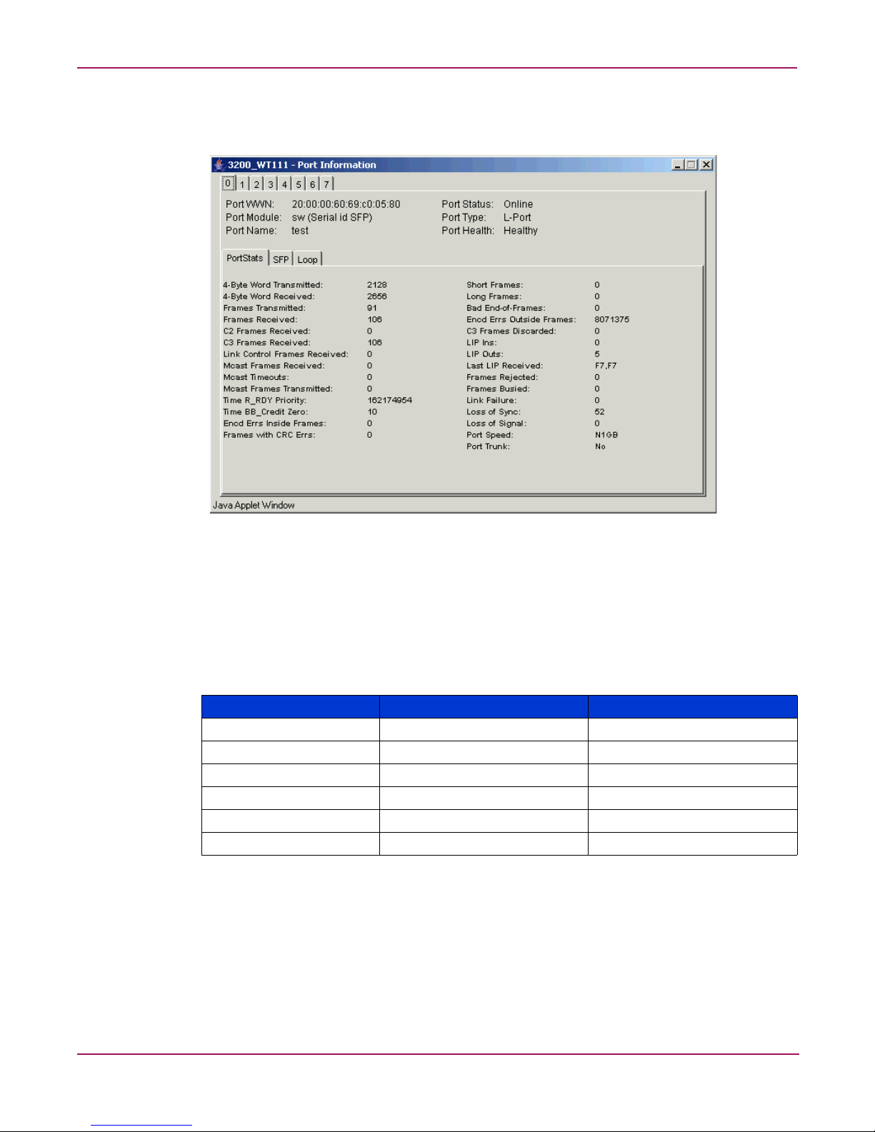
On original page 33, under the heading “Port Information View,” replace original
Figure 5, “Port information view,” with the following:
Figure 1: Port information view
On original pages 36 and 37, replace the entire “Workstation Requirements” section
with the following:
Table 2 identifies the supported browsers, operating systems, and Java
TM
Plug-ins for this
release.
Table 2: Supported platforms
Operating system Browser Java plug-in
RedHat Linux® 9.0 Mozilla 1.6 1.4.2_03
Solaris 2.8 Mozilla 1.6 1.4.2_03
Solaris 2.9 Mozilla 1.6 1.4.2_03
Windows® 2000 Internet Explorer 6.0 1.4.2_03
Windows 2003 Internet Explorer 6.0 1.4.2_03
Windows XP Internet Explorer 6.0 1.4.2_03
Adequate RAM is required on Windows systems as follows:
■ 128 MB or more RAM for fabrics comprising 10 switches or fewer
■ 256 MB or more RAM for fabrics comprising 15 switches or fewer
■ 512 MB or more RAM for fabrics comprising more than 15 switches
A minimum of 8 MB of video RAM is also recommended.
18 Fabric OS 3.x Document Addendum
Page 19

On original page 38, replace the entire “Installing a Web Browser” section with the
following:
If not already installed, install one of the following browsers:
■ Internet Explorer 6.0
■ Mozilla 1.6
For instructions on installing Mozilla 1.6 on Solaris 2.8 and Solaris 2.9, refer to the following
web site:
http://ftp27f.newaol.com/pub/mozilla.org/mozilla/releases/mozilla1.6/README
Note: This URL is subject to change without notice.
On original pages 38 and 39, replace the entire “Configuring the Web Browser”
section with the following:
Configuring the Web Browser
Advanced Web Tools user guide
Specific browser settings are required for the correct operation of Web Tools with Internet
Explorer or Mozilla (supported on Solaris only).
Configuring Internet Explorer
Correct operation of Web Tools with Internet Explorer requires specifying the appropriate
settings for browser refresh frequency. Browser pages should be refreshed frequently to ensure
the correct operation of Web Tools.
To set the refresh frequency:
1. Select Preferences from the Edit menu.
2. Select the General tab and click Settings (under Temporary Internet Files).
3. Under Check for newer versions of stored pages, select Every visit to the page.
Configuring Mozilla
Some browsers use local cache copies of .jar files and image files to improve performance
(depending on the options selected in the browser), which can cause incorrect displays in Web
Tools. The Web browser cache must be cleared before invoking Web Tools.
To clear the cache and set the refresh frequency:
1. Select Edit > Preferences.
2. Click Advanced in the Category box to expand it and then click Cache.
3. On the Cache panel, click Clear Cache.
4. Under Compare the page in the cache to the page on the network, select Every time I
view the page.
5. Click OK.
19Fabric OS 3.x Document Addendum
Page 20

Advanced Web Tools user guide
On original page 40, replace the following text:
Installing the Java Plug-in on Windows XP, 2000, or NT
To determine the version of the Java Plug-in installed on Windows XP, NT, or 2000, and
install if necessary:
With the this text:
Installing the Java Plug-in on Windows XP, 2000, or 2003
To determine the version of the Java Plug-in installed on Windows XP, 2000, or 2003, and
install if necessary:
On original page 41, under the heading “Licensing Web Tools on the Switch,” add the
following heading and text:
Two and Four Domain Fabric Licensing
If your fabric includes a switch with a license for a limited number of switches in the fabric
and the fabric exceeds the switch limit indicated in the license, Web Tools allows a 45-day
grace period in which you can still monitor the switch.
Web Tools displays warning messages periodically, informing you that your fabric size
exceeds the supported switch configuration limit and telling you how long you have before
Web Tools will be disabled. After the 45-day grace period, you will no longer be able to
launch Web Tools from the switch with the limited switch license, if that switch still exceeds
the switch limit. Two domain/four domain fabric licensing is applicable only to 2 Gbps
switches.
20 Fabric OS 3.x Document Addendum
Page 21
Advanced Web Tools user guide
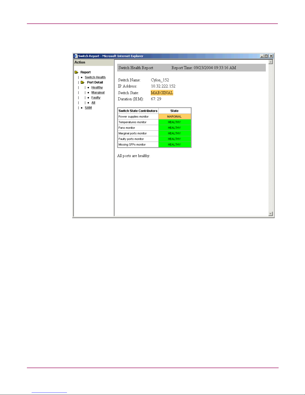
On original page 65, under the heading “Switch Status Example,” replace original
Figure 13, “Switch status window,” with the following:
Figure 2: Switch status window
On original page 66, under the heading “Using the Switch Status Button,” add the
following at the end of the procedure:
6. Optional: Click the underlined links in the left panel to display detailed information about
ports and Switch Availability Monitoring (SAM). Figure 3 shows an example of the Port
Detail report.
7. Optional: Mouse-over the Action field and click an action to:
■ Refresh the information displayed in the report
■ Customize the report
■ View the data in raw XML format
■ View the style sheet for the report
■ View the XML schema for the report
21Fabric OS 3.x Document Addendum
Page 22
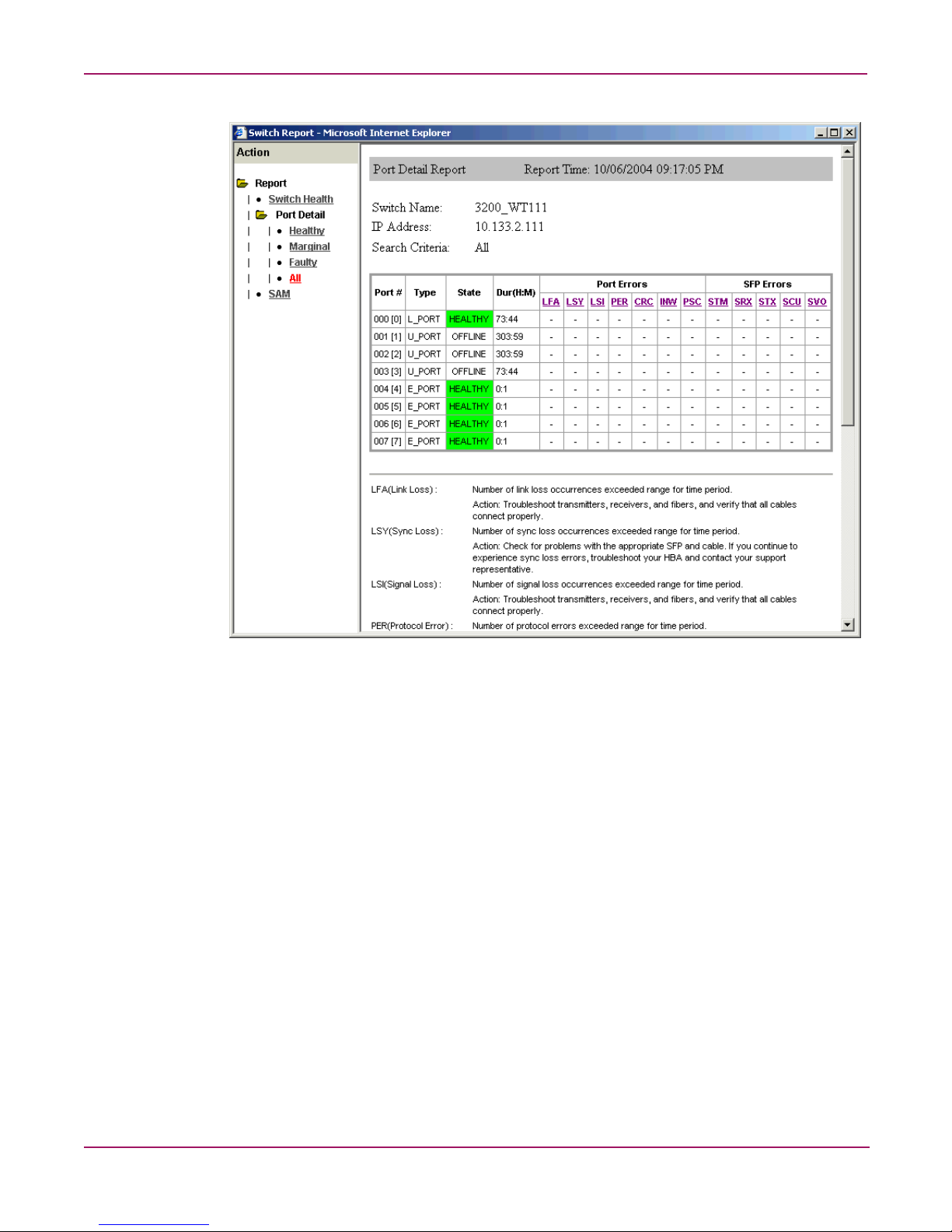
Advanced Web Tools user guide
Figure 3: Switch status window, port detail
22 Fabric OS 3.x Document Addendum
Page 23
Advanced Web Tools user guide
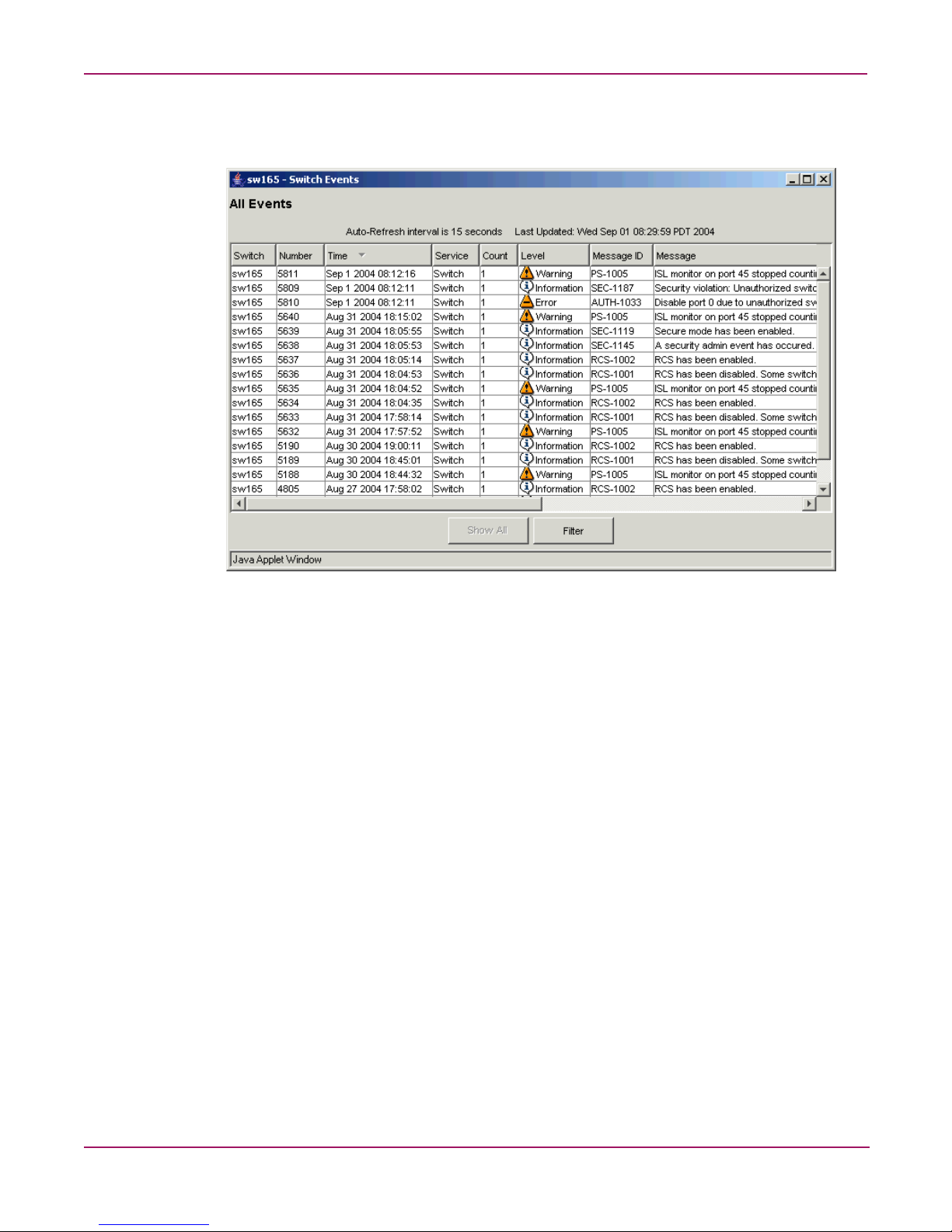
On original page 67, under the heading “Switch Events Example,” replace original
Figure 14, “Switch events window,” with the following:
Figure 4: Switch events window
On original page 67, under the heading “About the Switch Events Button,” add the
following:
Filtering Switch Events
You can filter the events in the Switch Events window by time and severity. You can apply
just one type of filter at a time or all types of filters at the same time. Click the Filter b utton to
display the Event Filter dialog box (Figure 5).
When a filter is applied, the Show All button is active in the Events Report and the types of
filters applied are identified at the top of the Events Report. To un-apply a filter, click the
Show All button in the Events Report.
23Fabric OS 3.x Document Addendum
Page 24
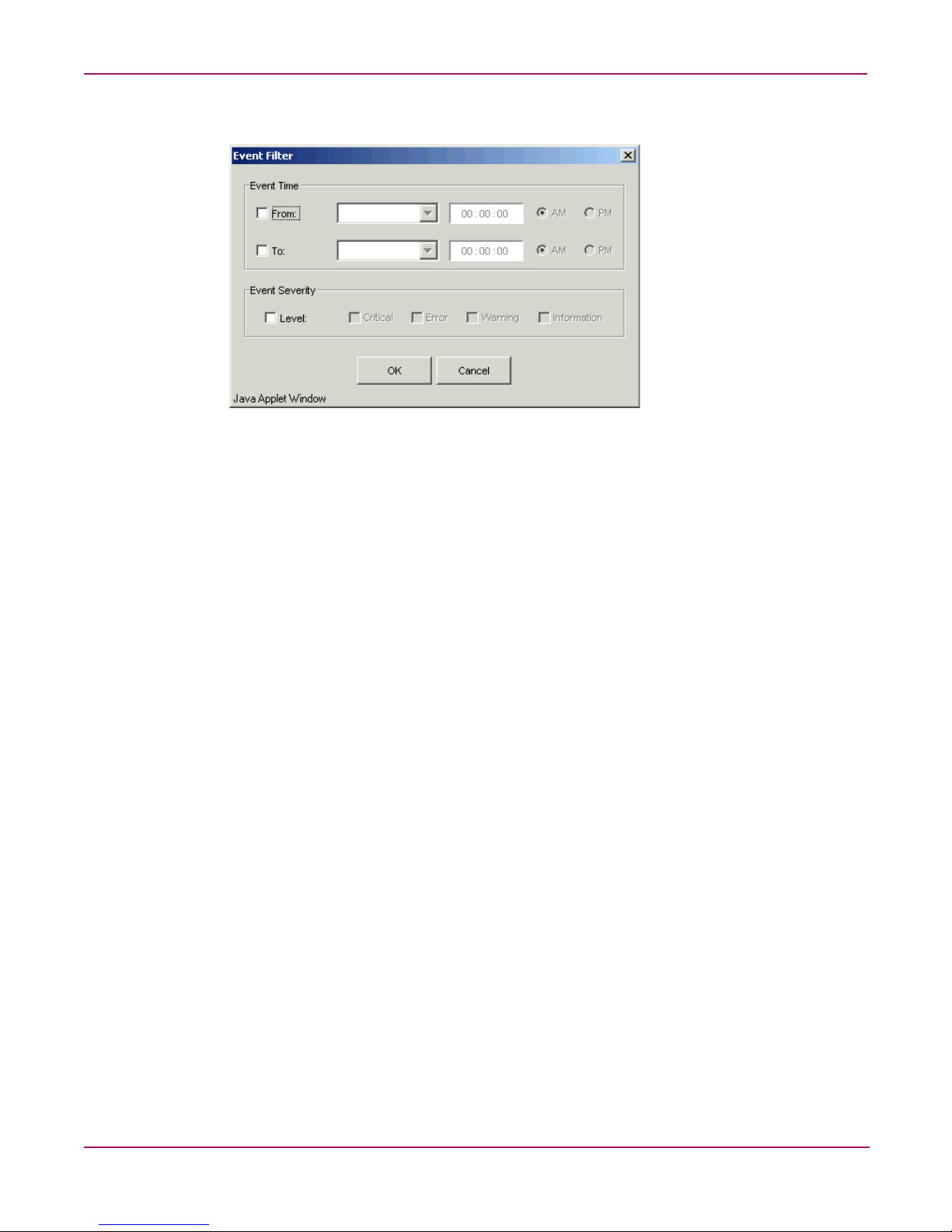
Advanced Web Tools user guide
Figure 5: Event filter dialog box
Filtering Events by Time Intervals
To filter events by time intervals:
1. Launch Web Tools.
2. Select the desired switch from the Fabric Tree.
The Switch View opens.
3. Select the Switch Events button from the Switch View.
A Switch Events Report appears.
4. Click Filter.
The Event Filter dialog box opens.
5. Optional: To filter events within a certain time period:
a. Click From and enter the start time and date in the fields.
b. Click To and enter the finish time and date in the fields.
6. Optional: T o filter all e v ents beginning at a certai n date and time, click From and enter the
start time and date in the fields.
7. Optional: To filter events up until a certain date and time, click To and enter the finish
time and date in the fields.
8. Click OK.
The filter is enabled and the enabled filter type is displayed in the Events Report.
Filtering Events by Event Severity
To filter events by event severity levels:
1. Launch Web Tools.
2. Select the desired switch from the Fabric Tree.
The Switch View opens.
24 Fabric OS 3.x Document Addendum
Page 25

Advanced Web Tools user guide
3. Select the Switch Events button from the Switch View.
A Switch Events Report appears.
4. Click Filter.
The Event Filter dialog box opens.
5. Click Level.
The event severity level check boxes are enabled.
6. Select the event levels you want to display.
7. Click OK.
The filter is enabled and the enabled filter type is displayed in the Events Report.
On original page 92, under the heading “Switch Admin Window Field Descriptions,”
modify original Table 17, “Switch Admin Window Field Descriptions,” as follows.
Delete the following row:
Reset Click this button to reset the field values to the last set of committed
changes. If the Apply button has not been pressed on this tab, the
parameters are returned to the original values the tab contained
when it was initially displayed.
In the last row (Status Icon) in the table, replace the following text:
A green square means the switch is enabled; a red square means the switch is disabled.
With this text:
The icon means the switch is enabled, and the icon means the switch is disabled.
25Fabric OS 3.x Document Addendum
Page 26
Advanced Web Tools user guide
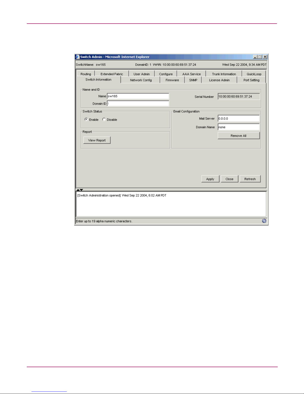
On original page 95, under the heading “Switch Information Tab Example,” replace
original Figure 18, “Switch Information Tab,” with the following:
Figure 6: Switch Information Tab
26 Fabric OS 3.x Document Addendum
Page 27
Advanced Web Tools user guide
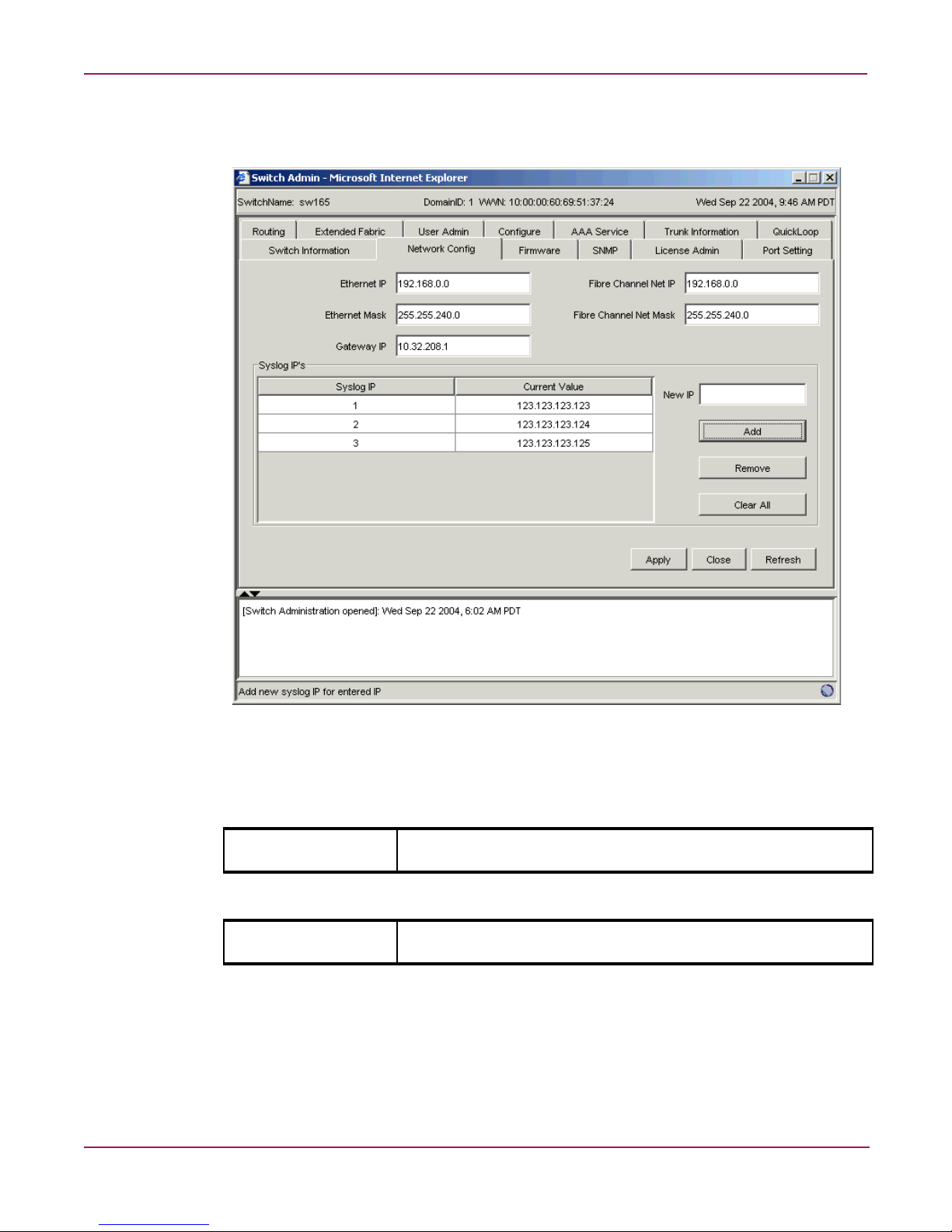
On original page 99, under the heading “Network Config Tab Example,” replace
original Figure 19, “Network Configuration Tab,” with the following:
Figure 7: Network Configuration Tab
On original page 100, in original Table 19, “Network Config Field Descriptions,” delete
the following row:
Syslog IP Field Enter any valid IP for a host and click the Add button to configure that
IP as a recipient of syslog messages.
And replace it with this row:
New IP Field Enter any valid IP for a host and click the Add button to configure that
IP as a recipient of syslog messages.
27Fabric OS 3.x Document Addendum
Page 28
Advanced Web Tools user guide
On original pages 103 through 105, replace the entire section, “About the
Upload/Download Tab,” with the following:
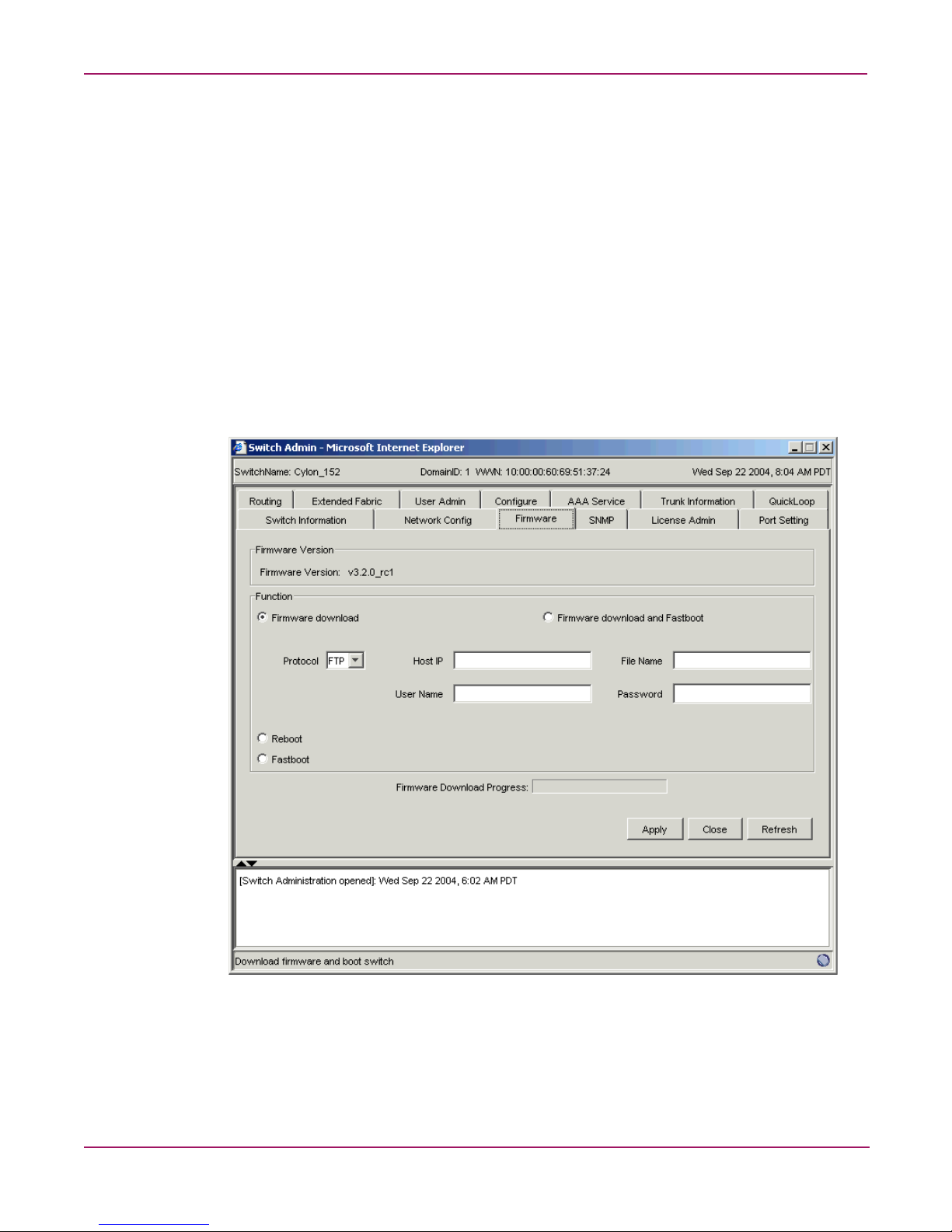
About the Firmware Tab
Use the Firmware tab to complete tasks such as:
■ Downloading firmware
■ Returning the switch to the original configuration
■ Rebooting the switch
You must provide host information for the download firmware task.
Firmware Tab Example
An example of the Firmware tab is shown in Figure 8.
Figure 8: Firmware Tab
28 Fabric OS 3.x Document Addendum
Page 29

Firmware Field Descriptions
The Firmware fields are described in Table 3.
Table 3: Firmware field descriptions
Field Description
Firmware Version This field indicates the current firmware version running on the
Firmware download Select the radio button to download firmware.
Firmware download
and Fastboot
Protocol Select a download protocol: FTP or RSH. FTP requires a password
Host IP Enter the IP address of the host.
File Name Enter the file name of the firmware package to be downloaded.
User Name Enter the User Name for the owner of the firmware package on the
Password Enter the password of the User who owns the firmware package on
Fastboot Select to perform a fast boot (no POST).
Reboot Select to perform a Reboot. Post is an optional feature. Check the
Firmware Download
Progress
Advanced Web Tools user guide
switch.
Select the radio button to download firmware and then perform a
fast boot of the switch.
to initiate file transfer; RSH does not. If you select RSH, the
password field is removed.
host.
the host. This option is displayed only if you select the FTP protocol.
POST checkbox to enable Reboot with POST; uncheck this box to
enable Reboot with no POST.
This is a progress bar indicating the firmware download progress.
On original page 106, replace the following heading:
Using the Upload/Download Tab
With this heading:
Using the Firmware Tab
29Fabric OS 3.x Document Addendum
Page 30

Advanced Web Tools user guide
On original page 106, under the heading “Performing a Firmware Download,” modify
the following information.
Replace steps 3 and 4 with the following:
1. Select the Firmware tab.
2. Select the Firmware download radio b utton.
Add the following after step 8:
You can monitor the progress by looking at the Firmware Download Progress bar on the
Firmware tab.
On original page 106, delete the sections “Backing Up a Firmware Config File” and
“Performing a Config Download to Switch.”
On original page 106, after the section “Performing a Firmware Download,” add the
following sections:
Performing a Fast Boot
To perform a fast boot of a switch:
1. Access the Switch Admin Window (see “About the Switch Admin Window”).
2. Enter the admin user name and password.
3. Select the Firmware tab.
4. Click Fastboot.
5. Click Apply.
Performing a Reboot
To perform a reboot of a switch:
1. Access the Switch Admin Window (see “About the Switch Admin Window”).
2. Enter the admin user name and password.
3. Select the Firmware tab.
4. Click Reboot.
5. Click Apply.
30 Fabric OS 3.x Document Addendum
Page 31

Advanced Web Tools user guide
On original page 109, under the heading “SNMP Tab Example,” replace original
Figure 22, “SNMP Tab,” with the following:
Figure 9: SNMP Tab (Secure Mode disabled)
On original page 110, in original Table 21, “SNMP Field Descriptions,” under the
heading “SNMP Field Descriptions,” modify the following information.
Delete the following row:
Trap Level Use to set the severity level of switch events that prompt SNMP traps.
Default is 0.
31Fabric OS 3.x Document Addendum
Page 32

Advanced Web Tools user guide
Delete the following row:
Permissions Displays the read/write access of a particular community string.
And replace it with these two rows:
Access Control Displays the read/write access of a particular community string.
Trap Level Use to set the severity level of switch events that prompt SNMP traps.
On original page 111, under the heading “Using the SNMP Tab to Set Trap Levels,”
replace step 4 with the following:
READ ONLY access means that a member of a community string has
the right to view, but cannot make changes. READ/WRITE access
means that a member of a community string can be both viewed and
make changes.
READ ONLY access means that a member of a community string has
the right to view, but cannot make changes. READ/WRITE access
means that a member of a community string can be both viewed and
make changes.
Default is 0.
6. For each recipient, select a Trap level from the pull-down menu. The level you select
refers to the Event level that prompts a trap. See “About the Switch Events Button.”
32 Fabric OS 3.x Document Addendum
Page 33

Advanced Web Tools user guide
On original page 112, under the heading “License Admin Tab Example,” replace
original Figure 23, “License Admin Tab,” with the following:
Figure 10: License Admin Tab
On original page 113, under the heading “License Admin Field Description,” delete the
following row from original Table 22, “License Admin Field Descriptions”:
License Key field Enter a license key to be added or double-click a license key from
the LicenseKey column to have it display in this field.
33Fabric OS 3.x Document Addendum
Page 34

Advanced Web Tools user guide
On original page 114, under the heading “Add a License to a Switch,” delete the
following steps 4 and 5 from the procedure:
4. Enter a new license key in the License Key field.
5. Click the Add button.
And replace them with these three steps:
4. Click the Add button.
5. Type or paste the new license key in the License Key field.
6. Click the Add License button.
On original page 114, under the heading “Remove a License From a Switch,” replace
step 4:
4. Enter the license key to remove, or double-click a license key from the License Key
column to display it in License Key field.
With this step:
4. Select a license key from the License Key column.
34 Fabric OS 3.x Document Addendum
Page 35

Advanced Web Tools user guide
On original page 116, under the heading “Port Settings Tab Example,” replace original
Figure 24, “Port Setting Tab,” with the following:
Figure 11: Port Setting Tab
On original page 118, under the heading “Enabling Trunking on a Port,” replace
step 4:
4. Check the Trunk box that corresponds to the port you wish to trunk.
With the following:
4. Check the Enabling Trunking box that corresponds to the port you want to trunk.
35Fabric OS 3.x Document Addendum
Page 36

Advanced Web Tools user guide
On original page 119, under the heading “Disabling a Port over Reboots,” replace
step 4:
4. Select the slot and port you want to disable over reboots.
With the following:
4. Select the port you want to disable over reboots.
On original page 120, under the heading “About the Configure Tab,” replace the first
sentence:
Use the Configure tab of the Administrative Interface to configure Fabric Parameters, Virtual
Channel parameters, Arbitrated Loop parameters, and System Services parameters.
With this text:
Use the Configure tab of the Administrative Interface to configure Fabric Parameters, Virtual
Channel parameters, Arbitrated Loop parameters, and System Services parameters, and to
back up and download the switch configuration file.
36 Fabric OS 3.x Document Addendum
Page 37

Advanced Web Tools user guide
On original page 121, under the heading “Configure (Fabric) Tab Example,” replace
original Figure 25, “Configure (Fabric) Tab,” with the following:
Figure 12: Configure (Fabric) Tab
37Fabric OS 3.x Document Addendum
Page 38

Advanced Web Tools user guide
On original page 122, in original Table 24, “Configure (Fabric) Field Descriptions,”
modify the following information.
Replace the corresponding rows with the following:
Datafield Size Use to configure (in bytes) the largest possible data field size. The
valid range is 256 – 2112.
Sequence Level Switching Select check box to enable frames of the same sequence from a
particular group to be transmitted together. When this option is
not selected, frames are transmitted interleaved among multiple
sequences. Under normal circumstances, sequence-level switching
should be disabled for better performance. However, some host
adapters have issues when receiving interleaved frames among
multiple sequences.
Suppress Class F Traffic When checked, translative addressing (which allows private
devices to communicate with public devices) is disabled.
Add the following row:
Switch PID Format Allows you to select a switch PID format from one of the following:
■ VC encoding – Set this format only if the fabric includes a
Fibre Channel Storage Switch 8 or Fibre Channel Storage
Switch 16. When set, the frame source and destination
address use an address format that is compatible with Fibre
Channel Storage Switch 8 and Fibre Channel Storage Switch
16.
■ Format 0 (16-port encoding) – Native format
■ Format 1 (0-base, 256-port encoding) – Core PID format
■ Format 2 (16-base, 256-port encoding) – Extended-edge PID
format
Delete the following row:
VC Encoded Address
Mode
38 Fabric OS 3.x Document Addendum
Set this mode only if the fabric includes a Fibre Channel Storage
Switch 8 or Fibre Channel Storage Switch 16. When set, the
frame source and destination address use an address format that
is compatible with Fibre Channel Storage Switch 8 and Fibre
Channel Storage Switch 16.
This option is grayed out if the switch is in interop mode.
Page 39

Advanced Web Tools user guide
On original page 124, under the heading “Configure (Virtual Channel) Tab Example,”
replace original Figure 26, “Configure (Virtual Channel) Tab,” with the following:
Figure 13: Configure (Virtual Channel) Tab
39Fabric OS 3.x Document Addendum
Page 40

Advanced Web Tools user guide
On original page 126, under the heading “Configure (Arbitrated Loop) Tab Example,”
replace original Figure 27, “Configure (Arbitrated Loop) Tab,” with the following:
Figure 14: Configure (Arbitrated Loop) Tab
40 Fabric OS 3.x Document Addendum
Page 41

Advanced Web Tools user guide
On original page 128, under the heading “Configure (System) Tab Example,” replace
original Figure 28, “Configure (System) Tab,” with the following:
Figure 15: Configure (System) Tab
41Fabric OS 3.x Document Addendum
Page 42

Advanced Web Tools user guide
On original page 129, after the section “Configure (System) Field Descriptions,” add the
following sections:
Configure (Upload/Download) Tab Example
An example of the Configure (Upload/Download) Tab is shown in Figure 16.
Figure 16: Configure (Upload/Download) Tab
Configure (Upload/Download) Field Descriptions
The fields available in the Configure (Upload/Download) Tab are described in Table 4.
42 Fabric OS 3.x Document Addendum
Page 43

Table 4: Configure (Upload/Download) Field Descriptions
Field Description
Function radio buttons Radio buttons indicating the function to be performed: Config
Protocol The protocol to use for the upload or download: either FTP or RSH.
Host IP The host IP address.
File Name The fully qualified path of the configuration file.
User Name The user name for the host.
Password The password for the host.
Config Upload
Progress
On original page 130, after the heading “Using the Configure Tab to Configure FAN
Frame Notification Parameters,” add the following sections:
Backing Up a Switch Config File
Advanced Web Tools user guide
Upload, Config Download, or Config Default.
A progress bar indicating the configuration upload or download
progress.
To back up a firmware configuration file:
1. Access the Switch Admin Window (see “About the Switch Admin Window.”)
2. Enter the admin user name and password.
3. Select the Switch Information tab.
4. Disable the switch.
5. Click the Apply button.
6. Select the Configure tab.
7. Select the Upload/Download subtab.
8. Select the Config Upload to Host radio button.
9. Enter the User Name, Password, and Host IP information.
10. Enter the name of the config file with a fully-qualified path.
11. Click Apply.
You can monitor the progress by observing the Upload/Download Progress bar on the
Configure tab.
Performing a Config Download to a Switch
To download a configuration to the switch:
1. Access the Switch Admin Window (see “About the Switch Admin Window.”)
2. Enter the admin user name and password.
3. Select the Switch Information tab.
4. Disable the switch.
5. Click the Apply button.
6. Select the Configure tab.
43Fabric OS 3.x Document Addendum
Page 44

Advanced Web Tools user guide
7. Select the Upload/Download subtab.
8. Select the Config Download to Switch radio button.
9. Enter the User Name, Password, and Host IP information.
10. Enter the name of the config file with a fully qualified path.
11. Click Apply.
You can monitor the progress by looking at the Upload/Download Progress bar on the
Configure tab.
12. Enable the switch.
On original page 132, under the heading “Routing (FSPF Route) Tab Example,” replace
original Figure 29, “Routing (FSPF Route) Tab,” with the following:
Figure 17: Routing (FSPF Route) Tab
44 Fabric OS 3.x Document Addendum
Page 45

Advanced Web Tools user guide
On original page 135, under the heading “Routing (Static Route) Tab Example,” replace
original Figure 30, “Routing (Static Route) Tab,” with the following:
Figure 18: Routing (Static Route) Tab
45Fabric OS 3.x Document Addendum
Page 46

Advanced Web Tools user guide
On original page 137, under the heading “Routing (Link Cost) Tab Example,” replace
original Figure 31, “Routing (Link Cost) Tab,” with the following:
Figure 19: Routing (Link Cost) Tab
On original page 141 under the heading “Configuring Link Cost,” add the following
text to the end of step 6:
Setting the value to 0 sets the link cost to the default value for that port.
46 Fabric OS 3.x Document Addendum
Page 47

On original page 143, replace the section “Extended Fabrics Tab Example” with the
following:
Extended Fabric Tab Example
An example of the Extended Fabric tab is shown in Figure 20.
Advanced Web Tools user guide
Figure 20: Extended Fabric Tab
On original pages 143 and 144, under the heading “Extended Fabric Field
Descriptions,” modify the following.
Replace the first sentence with:
The fields available in the Extended Fabric tab are described in Table 33.
47Fabric OS 3.x Document Addendum
Page 48

Advanced Web Tools user guide
In original Table 33, “Extended Fabric Field Descriptions,” delete the following rows:
Extended Fabric Mode
Enable Click the radio button to enable the Extended Fabric mode. The
Disable Click to disable the Extended Fabric Mode.
VCXLT Link Init Enabled Check the box to enable Virtual Channel link translation. See “About
switch must be disabled to enable the Extended Fabric mode.
the Upload/Download Tab.”
Replace the following row:
Port Speed Displays the current port speed. The possible port speeds are
described in “About the Upload/Download Tab.”
With this row:
Port Speed Displays the current port speed. The possible port speeds are
described in “About the Upload/Download Tab.”
On original page 145, under the heading “Using the Extended Fabric Tab to Configure
a Port For Long-Distance,” delete steps 4 and 5:
4. Click the Enable radio button.
5. Check the VCXLT box.
In step 6, delete the following text:
For information about the various distances, see “About the Upload/Download Ta b. ”
48 Fabric OS 3.x Document Addendum
Page 49

On original page 145, after the section “Using the Extended Fabric Tab to Configure a
Port For Long-Distance,” add the following sections:
About the AAA Service Tab
Use the AAA Service tab to manage the RADIUS server. Through the AAA Service tab, you
can perform the following tasks:
■ Enable and disable the RADIUS server
■ Configure the RADIUS server
■ Modify the RADIUS server
■ Modify the order of the RADIUS servers
■ Remove a RADIUS server
AAA Service Tab Example
An example of the AAA Service tab is shown in Figure 21.
Advanced Web Tools user guide
Figure 21: AAA Service Tab
49Fabric OS 3.x Document Addendum
Page 50

Advanced Web Tools user guide
AAA Service Tab Field Descriptions
Descriptions of the fields available in the AAA Service tab are shown in Table 5.
Table 5: AAA Service Tab Field Descriptions
Field Description
Primary AAA Service Displays the name of the primary AAA service.
Secondary AAA Service Displays the name of the secondary AAA service.
RADIUS Configuration
RADIUS Server Displays the name of the RADIUS server, which is either an IP
address or a Dynamic Name String (DNS).
Port Displays the port number.
Timeouts Displays the timeout time, in minutes.
Authentication Displays the authentication protocol: either CHAP or PAP.
Using the AAA Service Tab
AAA Services
Enabling and Disabling the RADIUS Server
You must be logged in as admin to configure the RADIUS server.
To configure the RADIUS server:
1. Access the Switch Admin Window (see “About the Switch Admin Module.”)
2. Enter the admin user name and password.
3. Select the AAA Service tab.
4. To enable RADIUS Service, select a RADIUS Service as the primary authentication,
authorization, and acounting (AAA) service. You can set the secondary AAA service as
None or Switch Database.
To disable RADIUS Service, select Switch Database as the primary AAA service and
None as the secondary service.
5. Click the Apply button.
Configuring the RADIUS Server
You can configure the RADIUS server even if it is disabled; you can configure up to five
RADIUS servers. You must be logged in as admin to configure the RADIUS server.
To configure the RADIUS server:
1. Access the Switch Admin Window (see “About the Switch Admin Module.”)
2. Enter the admin user name and password.
3. Select the AAA Service tab.
4. Click Add. You can configure up to five RADIUS servers. If five RADIUS servers are
already configured, the Add button is disabled.
50 Fabric OS 3.x Document Addendum
Page 51

The RADIUS Configuration dialog box opens.
5. Enter the RADIUS server name, which should be a valid IP address or DNS. Each
RADIUS server should have a unique IP address or DNS name for the RADIUS server.
6. Optional: Enter the port number.
7. Optional: Enter the secret string.
8. Optional: Enter the timeout time in minutes.
9. Optional: Select an authentication protocol from CHAP or P AP. The default value is CHAP
and, if you do not change it, CHAP will be the authentication protocol.
10. Click OK.
11. Click the Apply button.
Modifying the RADIUS Server
To modify the RADIUS server:
1. Access the Switch Admin Window (see “About the Switch Admin Module.”)
2. Enter the admin user name and password.
3. Select the AAA Service tab.
4. Select a RADIUS server from the RADIUS Configuration list.
Advanced Web Tools user guide
5. Click Modify.
The RADIUS Configuration dialog box opens.
6. Edit the RADIUS server name, which should b e a valid IP address or Dynamic Name
String (DNS). Each RADIUS server should hav e a unique IP address or DNS name for the
RADIUS server.
7. Optional: Edit the port number.
8. Optional: Edit the secret string.
9. Optional: Edit the timeout time in minutes.
10. Optional: Select an authentication protocol from CHAP or PAP. The default value is
CHAP; if you do not change it, CHAP will be the authentication protocol.
11. Click OK.
12. Click the Apply button.
Modifying the RADIUS Server Order
The RADIUS servers are contacted in the order they are listed, starting from the top of the list.
To modify the order that the RADIUS servers are contacted:
1. Access the Switch Admin Window (see “About the Switch Admin Module.”)
2. Enter the admin user name and password.
3. Select the AAA Service tab.
4. Select a RADIUS server from the RADIUS Configuration list.
5. Click the up and down arrows to rearrange the order of the RADIUS servers.
6. Click OK.
7. Click the Apply button.
51Fabric OS 3.x Document Addendum
Page 52

Advanced Web Tools user guide
Removing a RADIUS Server
To remove a RADIUS server:
1. Access the Switch Admin Window (see “About the Switch Admin Module.”)
2. Enter the admin user name and password.
3. Select the AAA Service tab.
4. Select a RADIUS server from the RADIUS Configuration list.
5. Click Remove. If there is no RADIUS server configured, the Remove button is disabled.
You cannot remove the only RADIUS server if the RADIUS service is the primary AAA
service.
The RADIUS server is not deleted until you apply the changes from the AAA Services
tab.
6. Click the Apply button.
On original page 146, under the heading “Trunk Information Tab Example,” replace
original Figure 33, “Trunk Information Tab,” with the following:
Figure 22: Trunk Information Tab
52 Fabric OS 3.x Document Addendum
Page 53

Advanced Web Tools user guide
On original page 174, replace original Figure 41, “Alarm Notification Tab of Fabric
Watch,” with the following:
Figure 23: Alarm Notification Tab
On original page 175, in original Table 41, “Alarm Notification Field Descriptions,”
replace the following row:
Selected Area Displays the configurable areas in the drop-down menu. The items
listed will change depending on the item selected in the
Navigation tree.
With this row:
Area Selection Displays the configurable areas in the drop-down menu. The items
listed change, depending on the item selected in the Navigation
tree.
53Fabric OS 3.x Document Addendum
Page 54

Advanced Web Tools user guide
On original page 177, delete the section “About the Threshold Configuration Tab.”
On original page 177, in the section “Threshold Configuration Tab Example,” replace
the text and the original Figure 42, “Threshold Configuration Area Configuration Tab,”
with the following:
The Threshold Configuration Tab > Trait Configuration Tab is shown in Figure 24.
Figure 24: Threshold Configuration Area Configuration Tab
54 Fabric OS 3.x Document Addendum
Page 55

Advanced Web Tools user guide
On original pages 177 and 178, add the following table after original Figure 42,
“Threshold Configuration Area Configuration Tab”:
Table 6: Threshold Configuration Tab Components
Component Description
Area Selection pull-down
menu
Trait Configuration tab Provides fields to configure Fabric Watch threshold boundaries
Alarm Configuration tab Provides fields to configure Fabric Watch alarms. For more
Element Configuration tab Provides fields to configure Fabric Watch threshold traits. For
Configuration Report tab Displays the Fabric Watch settings for the class that you select
Lists the areas of thresholds that you can configure. The areas
that appear in the pull-down menu depend on the class that
you select from the Fabric Watch Navigation tree.
and alarms. For more information, see “Trait Configuration
Tab.”
information, see “Alarm Configuration Tab.”
more information, see “Element Configuration Tab.”
from the Fabric Watch navigation tree. For more information,
see “Configuration Report Tab.”
On original page 178, before the section “Threshold Notification Fields Descriptions,”
insert the following sections:
Trait Configuration Tab
Table 7 describes the components of the Trait Configuration tab.
Table 7: Trait Configuration Components
Unit field Sets or displays the selected unit values used for the chosen area.
Time Base pull-down
menu
Low Boundary field Sets or displays the number of low boundaries (the lowest limit at
High Boundary field Sets or displays the number of high boundaries (the highest limit
Buffer Size field Sets or displays the threshold boundary buffer size of the selected
Activate Level radio
buttons
Component Description
Depending on the area of interest, this is figured in units of
downs, reconfigs, errors, changes, logins, and so on.
Sets or displays the basic unit of time in which events are
recorded for the selected area. The units available from the
pull-down menu are none, second, minute, hour, or day.
which an element does not trigger an event) for the selected area.
at which an element does not trigger an event) for the selected
area.
area.
Selects either System Default or Custom Defined to indicate which
traits are to be activated.
55Fabric OS 3.x Document Addendum
Page 56

Advanced Web Tools user guide
Alarm Configuration Tab
Table 8 lists and describes the components of the Alarm Configuration tab.
Table 8: Alarm Configuration Components
System Default and
Custom Defined
checkboxes
Activate Level radio
buttons
On original page 183, replace original Figure 43, “Email Configuration Tab,” with the
following:
Component Description
Select Alarm settings for Errorlog, SNMP, RAN, Portlog, and
Email to be active on the switch side.
Select either System Default or Custom Defined to indicate which
traits are to be activated.
Figure 25: Email Configuration Tab
56 Fabric OS 3.x Document Addendum
Page 57

Advanced Web Tools user guide
On original page 181, under the heading “Configuring Boundary and Alarm Settings,”
replace the procedure in the section with the following:
To configure threshold boundaries and alarms, perform the following steps:
1. Access Fabric Watch (see “Access Fabric Watch.”)
2. In the Fabric Watch Navigation tree, click the class that you want configure.
3. Select the Threshold Configuration tab.
4. Select the Trait Configuration subtab.
5. From the Select Area pull-down menu, select the area that you want to configure.
The System Default traits are displayed for the selected class and area. If you do not want
to change the system default settings, you do not need to finish the steps in this procedure.
If you want to change the system default settings, proceed to the next step.
6. Enter custom values in the trait fields (such as Unit, Hig h Boun dary, and Low Boundary)
in the Traits partition.
7. Select the Custom Defined radio button.
8. Click Apply.
9. Select the Alarm Configuration tab.
The System Default alarms are displayed for the selected class and area. If you do not
want to change the system default settings, you do not need to finish the steps in this
procedure.
If you want to change the system default settings, proceed to the next step.
10. Click a check box to set an alarm for an event type (Changed, exceeded, below, above, or
in between) and the corresponding alarm action (ERROR_LOG, SNMP_TRAP,
RAPI_TRAP, or EMAIL_ALERT).
11. Click Custom Defined in the Activate Level area.
12. Click Apply.
On original page 182, under the heading “View an Alarm Configuration Report,”
modify the following information.
In the procedure, replace step 5:
5. Select the alarm area report to be viewed from the Area drop-down menu.
With this text:
5. Select the alarm area report to be viewed from the Area Selection drop-down menu.
Delete step 6.
57Fabric OS 3.x Document Addendum
Page 58

Advanced Web Tools user guide
On original page 184, replace original Table 45, “Email Configuration Field
Descriptions,” with the following:
Table 9: Email Configuration Field Descriptions
Enabled/Disabled Select the Enabled or Disabled radio button to enable or disable
Recipient Email Address Enter a valid mail recipient email address.
Test Email Alert
Send Test Email Select this button to send a validation email.
On original page 190, in the section “About Fabric Events,” replace the text with the
following:
The Fabric Events window provides a running log of events for all switches in the fabric.
Events are displayed for all switches in the fabric in the Fabric Events window. Fabric events
can be collected only for switches that have the same security le vel as the launch switch.
Fabric events are not automatically polled. You must click Refresh from the Fabric Events
window to poll fabric events. For switches that have a different level of security from the
launch switch, a number is displayed, indicating how many switches have no events reported
from the last polling. For detailed information on the switch names and reasons for not polling
(if available), click Details.
Field Description
Email Alert Status
email alarm notifications.
Email Information
58 Fabric OS 3.x Document Addendum
Page 59

Advanced Web Tools user guide
On original page 190, under the heading “Fabric Events Example,” replace original
Figure 45, “The Fabric Events Window,” with the following:
Figure 26: The Fabric Events Window
On original page 191, after the section “Accessing Fabric Events,” add the following
sections:
Filtering Fabric Events
You can filter the events in the Fabric Events window by time and severity. You can apply just
one type of filter at a time or all types of filters at the same time. Click the Filter button to
display the Event Filter dialog box.
When a filter is applied, the Show All button is active in the Events Report and the types of
filters applied are identified at the top of the Events Report. To un-apply a filter, click the
Show All button in the Events Report.
Filtering Events by Time Intervals
To filter events by time intervals:
1. Access Web Tools.
2. Find the Fabric tool bar.
3. Select the Fabric Events icon in the lower corner of the Fabric Tree.
The Fabric Events window opens.
4. Click Filter.
The Event Filter dialog box opens.
59Fabric OS 3.x Document Addendum
Page 60

Advanced Web Tools user guide
5. Optional: To filter events within a certain time period:
a. Click From and enter the start time and date in the fields.
b. Click To and enter the finish time and date in the fields.
6. Optional: T o filter all e v ents beginning at a certai n date and time, click From and enter the
start time and date in the fields.
7. Optional: To filter events up until a certain date and time, click To and enter the finish
time and date in the fields.
8. Click OK.
The filter is enabled and the enabled filter type is displayed in the Events Report.
Filtering Events by Event Severity
To filter events by event severity levels:
1. Access Web Tools.
2. Find the Fabric tool bar.
3. Select the Fabric Events icon in the lower corner of the Fabric Tree.
The Fabric Events window opens.
4. Click Filter.
The Event Filter dialog box opens.
5. Click Level.
The event severity level check boxes are enabled.
6. Select the event levels you want to display.
7. Click OK.
The filter is enabled and the enabled filter type is displayed in the Events Report.
60 Fabric OS 3.x Document Addendum
Page 61

Advanced Web Tools user guide
On original page 195, under the heading “Name Server Example,” replace original
Figure 47, “Name Server Table Window,” with the following:
Figure 27: Name Server Table Window
On original pages 195 and 196, under the heading “Name Server Field Descriptions,”
modify the following information.
In original Table 49, “Name Server Description of Fields and Buttons,” add the
following rows:
Detail View Select to display Name Server information for a particular device.
Accessible Devices Select to display the zone members of a particular device.
61Fabric OS 3.x Document Addendum
Page 62

Advanced Web Tools user guide
On original page 196, replace original Table 50, “Name Server Description of
Columns,” with the following:
Table 10: Name Server Description of Columns
Domain # Displays the domain ID of the switch to which the device is
Port # Displays the number of the switch port to which the device is
Port ID Displays the port ID of the device (24-bit hexadecimal value).
Port Type Displays the port type of the device (N for fabric direct-attached
Device Port WWN Displays the World Wide Name of the device port.
Device Node WWN Displays the World Wide Name of the device node.
Device Name Displays the symbolic name of the device assigned through the
WWN Company ID Displays the vendor company based on device WWN.
Virtual vs. Physical Displays the type of device: either virtual or physical.
Host vs. Target Displays the type of device: either host or target.
Member of Zones Displays the zones to which this device belongs. This column does
Member of Aliases Displays the aliases to which this device is assigned, at both device
FC4 Type Displays the Fibre Channel FC4 layer types supported by the
Class Of Service Displays the Fibre Channel classes of service supported by the
Fabric Port Name Displays the name of the fabric port in use by the device.
Fabric Port WWN Displays the World Wide Name of the fabric port.
Port IP Address Displays the IP address of the fabric port.
Hard Address Displays the hard address of the fabric port.
Column Description
connected.
connected.
port or NL for fabric direct-attached loop port).
SCSI INQUIRY command.
not update when the table is refreshed. To view updated zoning
information, close and reopen the Name Server Table.
port and node levels.
device, such as IP or FCP.
device.
On original page 197, after the section “Viewing the Name Server,” add the following
sections:
Displaying Name Server Information for a Device
To display Name Server information for a particular device:
1. Access the Switch Explorer view.
2. Select the Name Server icon in the Fabric Tool Bar.
The Name Server window opens.
62 Fabric OS 3.x Document Addendum
Page 63

3. Select a device from the Domain column and then click Detail View.
The Name Server Information dialog box displays information specific to that device.
Displaying Zone Members of a Device
To display the Zone Members of a particular device:
1. Access the Switch Explorer view.
2. Select the Name Server icon in the Fabric Tool Bar.
The Name Server window opens.
3. Select a device from the Domain column and then click Accessible Devices.
The Zone Accessible Devices dialog box displays accessible zone member information
specific to that device.
On original page 204, under the heading “Using the Zone Administration Window,”
add the following information:
The information in the Zone Admin module is collected from the selected switch. The Zone
Admin icon is displayed in the Fabric Toolbar only if a Zoning license is installed on the
switch. If secure mode is enabled, Zoning can be administered only from the primary FCS
switch. If the selected switch has a Zoning license installed but is not the primary switch, the
Zone Admin icon is displayed in the Fabric Toolbar but not activated.
For specific information regarding secure fa brics, refer to the HP Stor a g eWorks Secure Fabric
OS Version 1.0 User Guide.
Advanced Web Tools user guide
When you click the Zone Admin icon from the Fabric T oolbar , you must log in as an admin to
launch the Zone Admin module. A live snapshot is taken of all the zoning conf igurations at the
time you launch the Zone Admin. To update the information displayed in the Zone Admin
module from the switch zone database, see “Refresh Zoning.”
Caution: Any changes you make in the Zone Admin module are held in a buffered
environment and do
Zone Admin module without saving your changes, your changes are lost. To save the
buffered changes you make in the Zone Admin module to the zoning database on the
switch, see “Saving Changes to an Existing Configuration.”
not
update the zoning database until you save them. If you close the
When using a mixed fabric—that is, a fabric containing v4.x, v3.x, and v2.x switches—you
should use the most advanced switches to control the fabric. For example, use the v4.x
switches as the Primary FCS, the location to perform zoning tasks, and the time server (CLI).
You should also use the most recently released firmware on your switches.
63Fabric OS 3.x Document Addendum
Page 64

Advanced Web Tools user guide
In the Zone Admin module, all WWNs also display vendor names. In the member selection
lists in the Zone Admin module that display fabric and device information, you can right-click
port and device nodes to display which aliases the port or device is a member of. In addition,
you can right-click the device nodes and click View Device Detail to display the Device
Detail view, which launches a window displaying detailed information about the selected
device (see Figure 28).
Figure 28: Device Detail View Example
On original page 205, under the heading “About the File Menu,” add the following row
to original Table 53, “File Menu Options”:
View Effective Configuration Select to view detailed information about the enabled zone
configuration.
On original page 205, after the section “About the File Menu,” add the following
section:
Viewing Detailed Information About the Enabled Zone Configuration
1. Access the Zone Administration window.
The Zone Configuration in effect at the time you launched the Zone Admin module is
identified in the top right corner. This information is updated only when you manually
refresh the Zone Admin contents by clicking the Refresh icon at the bottom right corner
of the Zone Admin window , or when you enable a configuration through the Zone Admin
module. If someone changes the effective zone configuration (outside of your Zone
Admin session) after you have launched the Zone Admin module, but before you have
refreshed the Zone Admin module (by clicking the Refresh icon in the bottom right
corner), the effective configuration displayed in the upper right corner is not updated.
64 Fabric OS 3.x Document Addendum
Page 65

Advanced Web Tools user guide
Caution: Clicking the Refresh icon in the lower right corner of the Zone Admin window
overwrites all local unsaved zoning changes. If anyone has made any changes to the
Zones outside of your Zone Admin session, those changes are applied.
2. Use one of the following methods to identify the most recently effective Zone
configuration without saving or applying any changes you have made in the Zone Admin
module:
■ Click File > View Effective Configuration in the Zone Admin window.
■ Click the enabled configuration icon in the Zone Admin window.
Both of these actions display the Effective Configuration dialog box. If no zone is enabled, a
message is displayed, indicating that there is no active zoning configuration on the switch.
On original page 208, in the section “Adding a WWN in the Zoning Database,” replace
the following heading:
Adding a WWN in the Zoning Database
With this heading:
Adding a WWN to Zoning Entities
Add the following step to the procedure:
5. The WWN is added to the Zone Admin buffer and can be used as a member.
On original page 208, in the section “Deleting a WWN in the Zoning Database,”
replace the following heading:
Deleting a WWN in the Zoning Database
With this heading:
Deleting a WWN in Zoning Entities
Add the following step to the procedure:
5. The WWN is deleted from the Zone Admin buffer.
65Fabric OS 3.x Document Addendum
Page 66

Advanced Web Tools user guide
On original page 209, in the section “Replacing a WWN in the Zoning Database,”
replace the following heading:
Replacing a WWN in the Zoning Database
With this heading:
Replacing a WWN in Zoning Entities
In step 5 of the procedure, replace the following text:
The old WWN is replaced in the Zoning database by the new WWN, including within any
Alias or Zone where the old WWN was a member.
With this text:
The old WWN is replaced in the Zone Admin buffer by the new WWN, including within any
Alias or Zone where the old WWN was a member.
On original page 211, under the heading “Refresh Zoning,” replace the following text
in step 2:
This refreshes the Zoning Database.
With this text:
This refreshes the Zone Admin buffer.
66 Fabric OS 3.x Document Addendum
Page 67

Advanced Web Tools user guide
On original page 217, under the heading “Alias Tab Example,” replace original Figure
51, “Alias Tab in the Zone Administration Window,” with the following:
Figure 29: Alias Tab
On original page 221, under the heading “Deleting an Alias,” replace the following
text in step 5:
The selected Alias is deleted from the zoning database.
With this text:
The selected Alias is deleted from the Zone Admin buffer.
On original page 221, under the heading “Renaming an Alias,” replace the following
text in step 6:
The Alias is renamed in the zoning database.
With this text:
The Alias is renamed in the Zone Admin buffer.
67Fabric OS 3.x Document Addendum
Page 68

Advanced Web Tools user guide
On original page 223, under the heading “Zone Tab Example,” replace original Figure
52, “Zone Tab in the Zone Administration Window,” with the following:
Figure 30: Zone Tab
On original page 227, under the heading “Deleting an Zone,” in step 5, replace the
following text:
The selected Zone is deleted from the zoning database.
With this text:
The selected Zone is deleted from the Zone Admin buffer.
On original page 228, under the heading “Renaming a Zone,” replace the following
text in step 6:
The zone is renamed in the zoning database.
With this text:
The zone is renamed in the Zone Admin buffer.
68 Fabric OS 3.x Document Addendum
Page 69

Advanced Web Tools user guide
On original pages 232 and 233, under the heading “Deleting an QuickLoop,” in step 5,
replace the following text:
The selected QuickLoop is deleted from the zoning database.
With this text:
The selected QuickLoop is deleted from the Zone Admin buffer.
On original page 233, under the heading “Renaming a QuickLoop,” replace the
following text in step 6:
The QuickLoop is renamed in the zoning database.
With this text:
The QuickLoop is renamed in the Zone Admin buffer.
On original page 234, under the heading “Fabric Assist Example,” replace original
Figure 54, “Fabric Assist Tab in the Zone Administration Window,” with the following:
Figure 31: Fabric Assist Tab
69Fabric OS 3.x Document Addendum
Page 70

Advanced Web Tools user guide
On original page 238, under the heading “Deleting an Fabric Assist Zone,” in step 5,
replace the following text:
The selected Fabric Assist Zone is deleted from the zoning database.
With this text:
The selected Fabric Assist Zone is deleted from the Zone Admin buffer.
On original page 239, under the heading “Renaming a Fabric Assist Zone,” replace the
following text in step 6:
The Fabric Assist Zone is renamed in the zoning database.
With this text:
The Fabric Assist Zone is renamed in the Zone Admin buffer.
On original page 240, under the heading “Config Tab Example,” replace original
Figure 55, “Config Tab in the Zone Administration Window,” with the following:
Figure 32: Config Tab
70 Fabric OS 3.x Document Addendum
Page 71

On original page 246, after the section “Creating a Configuration Analysis Report,”
add the following section:
Displaying an Initiator/Target Accessibility
1. Access the Zone Administration window. See “Accessing the Zone Administration
Window” for more information.
2. Select the Config tab.
3. Select a Configuration to be analyzed from the Name drop-down menu.
4. Click the Device Accessibility button.
The Initiator/Target Accessibility Matrix for Config- Device Selection dialog box opens.
5. Select devices you want displayed in the accessibility matrix; you can select the radio
button for all devices in the fabric or for a subset of the devices.
If you select a subset, you must click the devices from the Select Devices list and then
click Add to move them to the Evaluate for Accessibility list.
6. Click OK.
The Initiator/Target Accessibility Matrix opens. You can mouse over a target to display
the symbolic name of the device. You can click a WWN to launch the device view for that
device. You can also right-click the device nodes and click View Device Detail to display
the Device Detail view, which launches a window displaying detailed information about
the selected device.
Advanced Web Tools user guide
On original page 267, delete the entire section “Web Tools and Netscape on Solaris.”
71Fabric OS 3.x Document Addendum
Page 72

Advanced Web Tools user guide
72 Fabric OS 3.x Document Addendum
Page 73

Zoning version user guide
This chapter contains updates to the HP StorageWorks Zoning Versio n 3.1.x/4.1.x User Guide,
part number AA-RS26C-TE.
On original page 17, under the heading “License Activation Using Web Tools,” replace
the following text:
6. Enter the license key in the License K ey f iel d and click Add. Th e feat ure is n o w activated.
With this text:
6. Click Add.
7. Enter the license key in the License Key field and click Add License. The feature is now
activated.
3
On original page 26, under the heading “Commands to Open a Transaction,” add the
following rows to the list:
zoneObjectCopy Copy a zone object.
zoneObjectExpunge Delete a zone object and remove it from member lists of other zone
objects.
zoneObjectRename Rename a zone object.
73Fabric OS 3.x Document Addendum
Page 74

Zoning version user guide
On page 30, under the heading “Detailed Zone Configuration Procedures,” add the
following:
Table 11 presents zoning database size limitations for various Fabric OS release versions.
Table 11: Zoning Database Limitations
Fabric OS Version Maximum Database Size (KB)
2.4.0 64
2.5.0 64
2.6.0 96
3.0.0 128
3.1.0 96
3.2.x 256
4.0.0, 4.1.0, 4.2.0 128
4.4.0 256
Note: Zoning databases larger than 96 KB are not supported on SAN Switch 2/8 EL and SAN
Switch 2/16 with 16 MB of memory.
74 Fabric OS 3.x Document Addendum
Page 75

Diagnostic and system error
messages reference guide
This chapter contains updates to the HP StorageWorks Diagnostic and System Error Messages
Version 3.1.x Reference Guide, part number AA-RUPZA-TE.
The following modules report new (AUTH and SEC) or modified messages in Fabric OS
v3.2.x:
■ AUTH
■ CONFIG
■ DIAG
■ FABRIC
■ MS
■ SEC
4
AUTH-AUTHCHANGE
Message
<timestamp>
INFO AUTH-AUTHCHANGE, 4, <text message>
Probable Cause
The AUTH database was modified. The text message can display the following
information:
■ Secret database was successfully updated.
■ Secret database was successfully removed.
Recommended Action
Verify that this change was intended.
Severity
INFO
75Fabric OS 3.x Document Addendum
Page 76

Diagnostic and system error messages reference guide
AUTH-AUTHCFGCHANGE
Message
<timestamp>
INFO AUTH-AUTHCFGCHANGE, 4, <text message>
Probable Cause
The authentication type or the group type was modified. The text message can display the
following information:
■ Authentication type was successfully set to fcap, dhchap, or fcap, dhchap.
■ Group type was successfully set to 0, 1, 2, 3, 4 or 0,1,2,3,4.
Recommended Action
Verify that this change was intended. If the change was intended, no action is required.
Severity
INFO
AUTH-AUTHCFGERROR
Message
<timestamp>
ERROR AUTH-AUTHCFGERROR, 2, <text message>
Probable Cause
The authentication type or the group type was not set. The text message can display the
following information:
■ Failed to set authentication to either fcap, dhchap, or fcap, dhchap.
■ Failed to set group type to either 0, 1, 2, 3, 4 or 0,1,2,3,4.
Recommended Action
Usually this problem is transient. Retry the command.
If the command fails consistently, copy the message, collect switch information using the
supportshow command, and contact your switch service provider.
Severity
ERROR
76 Fabric OS 3.x Document Addendum
Page 77

AUTH-AUTHINFO
Message
<timestamp>
INFO AUTH-AUTHINFO, 4, <text message>
Probable Cause
An INFO-level authentication failure occurred. The text message can display the
Failed to create a timer for authentication message.
Recommended Action
Usually this problem is transient. Reinitialize authentication by issuing the switchdisable
and switchenable commands or the portdisable and portenable commands.
Severity
INFO
Diagnostic and system error messages reference guide
AUTH-AUTHWARN
Message
<timestamp>
WARNING AUTH-AUTHWARN, 3, <text message>
Probable Cause
A WARNING-level authentication failure occurred. The text message can display the
following information:
■ Failed to allocate memory for various authentication payloads or messages.
Recommended Action
Usually this problem is transient. Reinitialize authentication by issuing switchdisable
and switchenable commands or the portdisable and portenable commands.
If the command fails consistently, copy the message, collect switch information using the
supportshow command, and contact your switch service provider.
Severity
WARNING
77Fabric OS 3.x Document Addendum
Page 78

Diagnostic and system error messages reference guide
AUTH-AUTHERROR
Message
<timestamp>
ERROR AUTH-AUTHERROR, 2, <text message>
Probable Cause
An ERROR-level authentication failure occurred. The text message displays more
information about the failure that occurred.
General authentication errors:
■ Authentication is rejected because the other side does not support authentication or a
required protocol.
■ Internal error due to data mismatch or corruption.
■ Various error types that relate to authentication configuration file such as empty file,
corruption file, or nonexistent file.
■ Failed to get information for authentication entry such as port or switch.
■ Failed to get security license.
■ Failed to validate switch or port name.
■ Disabled port due to unauthorized switch that is not configured in the SCC policy.
Specific FCAP/SLAP authentication errors:
■ Failed to retrieve switch certificate.
■ Failed to sign data for FCAP/SLAP authentication messages.
■ Incorrect length or content in the FCAP/SLAP authentication payload, such as nonce
length, signature length, or certificate length.
■ Failed to verify different types of authentication messages (for example, certificate,
nonce, or signature data) for FCAP/SLAP authentication protocol.
Specific DH-CHAP authentication errors:
■ Failed to update/remove secret database when using secAuthSecret command.
■ Failed to retrieve secret value.
■ Failed to generate various values for DH-CHAP authentication messages, such as DH
group, hash value, challenge message, or response value.
■ Incorrect length or content in the authentication payload, such as challenge length, DH
group length, hash list length, or response length.
■ Failed to verify different types of authentication messages (for example, reply or
success) for DH-CHAP authentication protocol.
Recommended Action
For a security license error, make sure that the security license is properly installed, using the
licenseshow command. Reinstall the license, if necessary, using the licenseadd
command.
78 Fabric OS 3.x Document Addendum
Page 79

Severity
Diagnostic and system error messages reference guide
For an unauthorized switch in the SCC policy, add the switch WWN to the SCC policy, using
the secpolicyadd command.
For a certificate retrieve error, make sure the switch certificate is properly installed, using the
pkishow command. Reinstall the certificate, if necessary, using the pkicert command.
For a secret retrieve error, make sure that the secret values are properly set. Reset the secret
values using the secauthsecret command.
For other internal errors (for example, bad payload, incorrect field length, or invalid object),
this might be a transient error. Use the switchdisable and switchenable commands
or portdisable and portenable commands to determine whether the problem is
consistent.
Other errors (for example, invalid nonce, signature, reply message, or response value) might
indicate that an invalid entity is trying to connect to the switch. Check the connection port to
verify that there is no security attack. Otherwise, use the switchdisable and
switchenable commands or portdisable and portenable commands to determine
whether the problem is consistent.
ERROR
CONFIG-PIDCHANGE_EXTENDED_EDGE
Message
<timestamp>
WARNING CONFIG-PIDCHANGE_EXTENDED_EDGE, 3, Switch PID format changed to
Format 2 ('Extended Edge PID Format').
Probable Cause
The PID format for the fabric was changed to Format 2, extended-edge PID. For more
information on PID format, refer to the HP StorageWorks Fabric OS Procedures Version
3.1.x/4.1.x User Guide.
Recommended Action
This message is for information purposes only. The entire fabric must be configured with the
same PID format or the fabric segments.
Severity
WARNING
79Fabric OS 3.x Document Addendum
Page 80

Diagnostic and system error messages reference guide
DIAG-BADINT
Message
<timestamp>
CRITICAL DIAG-BADINT, 1, <test name>, pass <number>,
Pt<port information> got interrupt,
int_status=0x<int number> when not expecting one,
Err# <error code>
Probable Cause
A port received an unexpected interrupt. This usually indicates an ASIC failure. This message
is generated by the centralmemorytest or the cmitest command. The error code
value is for internal use only.
Recommended Action
For the HP StorageWorks SAN Switch 2/16, replace the motherboard FRU.
For the HP StorageWorks SAN Switch 2/8 EL, replace the entire switch.
Severity
CRITICAL
DIAG-BUS_TIMEOUT
Message
<timestamp>
CRITICAL DIAG-BUS_TIMEOUT, 1, <test name>,
Pt<port information> BTO accessing <Register Name> Register at Address
<address>,
Err# <error code>
Probable Cause
The ASIC register or ASIC SRAM did not respond to an ASIC data access. This usually
indicates an ASIC failure. This message is generated by the portregtest or the
sramretentiontest command. The error code value is for internal use only.
Recommended Action
For the SAN Switch 2/16, replace the motherboard FRU.
For the SAN Switch 2/8 EL, replace the entire switch.
Severity
CRITICAL
80 Fabric OS 3.x Document Addendum
Page 81

DIAG-CAMFLTR
Message
<timestamp>
CRITICAL DIAG-CAMFLTR, 1, <test name>, pass <number>,
Pt<port info> Failed Filter Test (test=<test number>, match:<cam type>),
filter <hit | nhit> on <actual filter number>(sb:<expected filter number>)
action type: <actual action>(sb:<expected action>)
Err# <error code>
Probable Cause
The ASIC internal logic failed. This usually indicates an ASIC failure. This message is
generated by the filtertest command. The error code value is for internal use only.
Recommended Action
For the SAN Switch 2/16, replace the motherboard FRU.
For the SAN Switch 2/8 EL, replace the entire switch.
Diagnostic and system error messages reference guide
Severity
DIAG-CAMINIT
Message
Probable Cause
CRITICAL
<timestamp>
CRITICAL DIAG-CAMINIT, 1, <test name>, pass <number>,
Pt<port information> Failed to Init: <additional message>,
Err# <error code>
A port failed to initialize due to one of the following reasons:
■ Switch is not disabled.
■ Diagnostic queue is absent.
■ Malloc failed.
■ Chip is not present.
■ Port is not in loopback mode.
■ Port is not active.
■ There was a software operational setup error or motherboard failure.
■ There occurred a retry, reboot, or replacement of motherboard assembly.
81Fabric OS 3.x Document Addendum
Page 82

Diagnostic and system error messages reference guide
This can be caused by a faulty cable or deteriorated SFP. It can also indicate more serious
problems in the motherboard or ASIC. This message is generated by the camtest command.
The error code value is for internal use only.
Recommended Action
Check for a faulty cable or deteriorated SFP. Replace the cable or SFP if necessary. If the
problem persists:
■ For the SAN Switch 2/16, replace the motherboard FRU.
■ For the SAN Switch 2/8 EL, replace the entire switch.
Severity
CRITICAL
DIAG-CAMSID
Message
Probable Cause
The ASIC failed the SID NO translation test. This usually indicates an ASIC failure. This
message is generated by the camtest command. The error code value is for internal use
only.
Recommended Action
For the SAN Switch 2/16, replace the motherboard FRU.
For the SAN Switch 2/8 EL, replace the entire switch.
Severity
CRITICAL
<timestamp>
CRITICAL DIAG-CAMSID, 1, <test name>, pass <number>,
Pt<port information> Failed SID [No] translation test,
SID received is 0x<Actual SID>, SID transmitted 0x<expected SID>,
Err# <error code>
82 Fabric OS 3.x Document Addendum
Page 83

DIAG-CAMSTAT
Message
<timestamp>
CRITICAL DIAG-CAMSTAT, 1, <test name>, pass <number>,
Pt<port information> Failed ALI: <idx>, ALPA: 0x<ALPA number> counter:
<cnt>
Err# <error code>
Probable Cause
The ASIC improperly counted the number of frames with CRC errors. This usually indicates
an ASIC failure. This message is generated by the statisticstest command. The
error code value is for internal use only.
Recommended Action
For the SAN Switch 2/16, replace the motherboard FRU.
For the SAN Switch 2/8 EL, replace the entire switch.
Diagnostic and system error messages reference guide
Severity
CRITICAL
DIAG-CLEAR_ERR
Message
<timestamp>
INFO DIAG-CLEAR_ERR, 3, Pt<port information> Diagnostics Error Cleared
Err# <error code>
Probable Cause
The port diag error flag (OK or BAD) is cleared. The error code value is for internal use
only.
Recommended Action
No action is required.
Severity
INFO
83Fabric OS 3.x Document Addendum
Page 84

Diagnostic and system error messages reference guide
DIAG-CMBISRF
Message
<timestamp>
CRITICAL DIAG-CMBISRF, 1, <test name>, pass <number>,
Pt<port information> BISR,BIST Self-Test Failed,
RAMs fail bitmap: is 0x<actual value> sb 0x<expected value> er 0x<err
value>,
Err# <error code>
Probable Cause
The ASIC central memory SRAMs did not complete the BISR within the timeout period. This
usually indicates an ASIC failure. This message is generated by the centralmemorytest
command. The error code value is for internal use only.
Recommended Action
For the SAN Switch 2/16, replace the motherboard FRU.
For the SAN Switch 2/8 EL, replace the entire switch.
Severity
CRITICAL
DIAG-CMBISRTO
Message
<timestamp>
CRITICAL DIAG-CMBISRTO, 1, <test name>, pass <number>,
Pt<port information> BISR,BIST Timed Out,
RAMs done bitmap: is 0x<actual value> sb 0x<expected value> er 0x<err
value>,
Err# <error code>
Probable Cause
The ASIC central memory SRAMs did not complete the BISR within the timeout period. This
usually indicates an ASIC failure. This message is generated by the centralmemorytest
command. The error code value is for internal use only.
Recommended Action
For the SAN Switch 2/16, replace the motherboard FRU.
For the SAN Switch 2/8 EL, replace the entire switch.
84 Fabric OS 3.x Document Addendum
Page 85

Severity
CRITICAL
DIAG-CMERRPTN
Message
<timestamp>
CRITICAL DIAG-CMERRPTN, 1, <test name>, pass <number>,
Pt<source port info>-Pt<destination port info> Offs <offset value> <err
str> detected at wrong port,
Checking Pt<check pt>: is <actual value> sb <expected value>,
Err# <error code>
Probable Cause
A problem was detected at the wrong port. This usually indicates an ASIC failure. This
message is generated by the centralmemorytest command. The error code v alue is
for internal use only.
Diagnostic and system error messages reference guide
Recommended Action
For the SAN Switch 2/16, replace the motherboard FRU.
For the SAN Switch 2/8 EL, replace the entire switch.
Severity
CRITICAL
DIAG-CMERRTYPE
Message
<timestamp>
CRITICAL DIAG-CMERRTYPE, 1, <test name>, pass <number>,
Pt<source port info>-Pt<destination port info> Offs <offset value> Wrong
Err Type,
Checking Pt<check pt>: is <actual value> (<err str>) sb <expected value>
(<err str>),
Err# <error code>
Probable Cause
The port got the wrong CMEM error type. This usually indicates an ASIC failure. This
message is generated by the centralmemorytest command. The error code v alue is
for internal use only.
85Fabric OS 3.x Document Addendum
Page 86

Diagnostic and system error messages reference guide
Recommended Action
For the SAN Switch 2/16, replace the motherboard FRU.
For the SAN Switch 2/8 EL, replace the entire switch.
Severity
CRITICAL
DIAG-CMICKSUM
Message
<timestamp>
CRITICAL DIAG-CMICKSUM, 1, <test name>, pass <number>,
Pt<source port info>-Pt<destination port info>: Pt<src/dst pt> Failed
[good/bad/not target] Cksum Test,
cmi_err bit6 is <actual value> sb <expeted value>, bad msg is from <CMI
bit>,
Err# <error code>
Probable Cause
The CMI message received failed. This usually indi cates an ASIC or motherboar d failure. This
message is generated by the cmitest command. The error code v alue is for internal use
only.
Recommended Action
For the SAN Switch 2/16, replace the motherboard FRU.
For the SAN Switch 2/8 EL, replace the entire switch.
Severity
CRITICAL
86 Fabric OS 3.x Document Addendum
Page 87

DIAG-CMIDATA
Message
<timestamp>
CRITICAL DIAG-CMIDATA, 1, <test name>, pass <number>,
Pt<source port info>-Pt<destination port info>: RX Data is <actual value>
sb <expected value> er 0x<err value>,
Err# <error code>
Probable Cause
The CMI data received did not match data transmitted. This usually indicates an ASIC or
motherboard failure. This message is generated by the cmitest command. The error
code value is for internal use only.
Recommended Action
For the SAN Switch 2/16, replace the motherboard FRU.
For the SAN Switch 2/8 EL, replace the entire switch.
Diagnostic and system error messages reference guide
Severity
CRITICAL
DIAG-CMIINVCAP
Message
<timestamp>
CRITICAL DIAG-CMIINVCAP, 1, <test name>, pass <number>,
Pt<source port info>-Pt<destination port info>: Pt<fail port> erroneously
got CMI Capture Flag (bit31 is 1),
Err# <error code>
Probable Cause
The ASIC unintentionally got a CMI capture flag. This usually indicates an ASIC or
motherboard failure. This message is generated by the cmitest command. The error
code value is for internal use only.
Recommended Action
For the SAN Switch 2/16, replace the motherboard FRU.
For the SAN Switch 2/8 EL, replace the entire switch.
Severity
CRITICAL
87Fabric OS 3.x Document Addendum
Page 88

Diagnostic and system error messages reference guide
DIAG-CMINOCAP
Message
<timestamp>
CRITICAL DIAG-CMINOCAP, 1, <test name>, pass <number>,
Pt<source port info>-Pt<destination port info>: RX Pt<fail port> Failed to
get CMI Capture Flag (bit31 is 0),
Err# <error code>
Probable Cause
The CMI recipient ASIC failed to get a CMI capture flag. This usually indicates an ASIC or
motherboard failure. This message is generated by the cmitest command. The error
code value is for internal use only.
Recommended Action
For the SAN Switch 2/16, replace the motherboard FRU.
For the SAN Switch 2/8 EL, replace the entire switch.
Severity
CRITICAL
DIAG-CMISA1
Message
Probable Cause
An attempt to send a CMI message from one ASIC to another failed. This usually indicates an
ASIC failure. This message is generated by the cmitest command. The error code
value is for internal use only.
Recommended Action
<timestamp>
CRITICAL DIAG-CMISA1, 1, <test name>, pass <number>,
Pt<source port info>-Pt<destination port info>: TX Pt<fail port> CMI
Self-Test Start bit30 s-a-1,
Err# <error code>
For the SAN Switch 2/16, replace the motherboard FRU.
For the SAN Switch 2/8 EL, replace the entire switch.
Severity
CRITICAL
88 Fabric OS 3.x Document Addendum
Page 89

DIAG-CMNOBUF
Message
<timestamp>
CRITICAL DIAG-CMNOBUF, 1, <test name>, pass <number>,
Pt<port information> No More Buffers,
Err# <error code>
Probable Cause
The port could not get any buffers. This usually indicates an ASIC failure. This message is
generated by the centralmemorytest command. The error code value is for internal
use only.
Recommended Action
For the SAN Switch 2/16, replace the motherboard FRU.
For the SAN Switch 2/8 EL, replace the entire switch.
Diagnostic and system error messages reference guide
Severity
CRITICAL
DIAG-DATA
Message
Probable Cause
The payload received b y a port did not match th e payload transmitted. Th is can be caused by a
faulty cable or deteriorated SFP. It can also indicate more serious problems in the motherboard
or ASIC. This message is generated by the crossporttest or portloopbacktest
command. The error code value is for internal use only.
Recommended Action
<timestamp>
CRITICAL DIAG-DATA, 1, <test name>, pass <number>,
Pt<source port info>-Pt<destination port info>: RX Data is 0x<actual value>
sb 0x<expected value> er 0x%<err value>,
Err# <error code>
Check for a faulty cable or deteriorated SFP. Replace the cable or SFP if necessary. If the
problem persists:
■ For the SAN Switch 2/16, replace the motherboard FRU.
■ For the SAN Switch 2/8 EL, replace the entire switch.
89Fabric OS 3.x Document Addendum
Page 90

Diagnostic and system error messages reference guide
Severity
CRITICAL
DIAG-ERRSTAT (2LONG)
Message
<timestamp>
CRITICAL DIAG-ERRSTAT (2LONG), 1, <test name>, pass <number>,
Pt<port information> FrmTooLong Error Counter is <number> sb 0,
Err# <error code>
Probable Cause
The Port Error Statistics counter is nonzero, which means that a Frame too long error
was detected when receiving frames. This can be caused by a faulty cable or deteriorated SFP.
It can also indicate more serious problems in the motherboard or ASIC. This message is
generated by the portloopbacktest or spinsilk command. The error code value
is for internal use only.
Recommended Action
Check for a faulty cable or deteriorated SFP. Replace the cable or SFP if necessary. If the
problem persists:
■ For the SAN Switch 2/16, replace the motherboard FRU.
■ For the SAN Switch 2/8 EL, replace the entire switch.
Severity
CRITICAL
90 Fabric OS 3.x Document Addendum
Page 91

DIAG-ERRSTAT (BADEOF)
Message
<timestamp>
CRITICAL DIAG-ERRSTAT (BADEOF), 1, <test name>, pass <number>,
Pt<port information> BadEOF Error Counter is <number> sb 0,
Err# <error code>
Probable Cause
The Port Error Statistics counter is nonzero, which means that a Bad end of file error
was detected when receiving frames. This can be caused by a faulty cable or deteriorated SFP.
It can also indicate more serious problems in the motherboard or ASIC. This message is
generated by the portloopbacktest or spinsilk command. The error code value
is for internal use only.
Recommended Action
Diagnostic and system error messages reference guide
Check for a faulty cable or deteriorated SFP. Replace the cable or SFP if necessary. If the
problem persists:
■ For the SAN Switch 2/16, replace the motherboard FRU.
■ For the SAN Switch 2/8 EL, replace the entire switch.
Severity
CRITICAL
DIAG-ERRSTAT (BADORD)
Message
<timestamp>
CRITICAL DIAG-ERRSTAT (BADORD), 1, <test name>, pass <number>,
Pt<port information> BadOrdSet Error Counter is <number> sb 0,
Err# <error code>
Probable Cause
The Port Error Statistics counter is nonzero, which means that a Bad symbol on
fiber-optic cable error was detected when receiving frames. This can be caused by a
faulty cable or deteriorated SFP. It can also indicate more serious problems in the motherboard
or ASIC. This message is generated by the portloopbacktest or spinsilk command.
The error code value is for internal use only.
91Fabric OS 3.x Document Addendum
Page 92

Diagnostic and system error messages reference guide
Recommended Action
Check for a faulty cable or deteriorated SFP. Replace the cable or SFP if necessary. If the
problem persists:
■ For the SAN Switch 2/16, replace the motherboard FRU.
■ For the SAN Switch 2/8 EL, replace the entire switch.
Severity
CRITICAL
DIAG-ERRSTAT (CRC)
Message
<timestamp>
CRITICAL DIAG-ERRSTAT (CRC), 1, <test name>, pass <number>,
Pt<port information> CRC_err Error Counter is <number> sb 0,
Err# <error code>
Probable Cause
The Port Error Statistics counter is nonzero, which means that a Cyclic redundancy
check on frame failed error was detected when receiving frames. This can be caused
by a faulty cable or deteriorated SFP. It can als o in dicate more serious problems in the
motherboard or ASIC. This message is generated by the portloopbacktest or
spinsilk command. The error code value is for internal use only.
Recommended Action
Check for a faulty cable or deteriorated SFP. Replace the cable or SFP if necessary. If the
problem persists:
■ For the SAN Switch 2/16, replace the motherboard FRU.
■ For the SAN Switch 2/8 EL, replace the entire switch.
Severity
CRITICAL
92 Fabric OS 3.x Document Addendum
Page 93

DIAG-ERRSTAT (DISCC3)
Message
<timestamp>
CRITICAL DIAG-ERRSTAT (DISCC3), 1, <test name>, pass <number>,
Pt<port information> DiscC3 Error Counter is <number> sb 0,
Err# <error code>
Probable Cause
The Port Error Statistics counter is nonzero, which means that a Discarded Class 3
frames error was detected when receiving frames. This can be caused by a faulty cable or
deteriorated SFP. It can also indicate more serious problems in the motherboard or ASIC. This
message is generated by the portloopbacktest or spinsilk command. The error
code value is for internal use only.
Recommended Action
Check for a faulty cable or deteriorated SFP. Replace the cable or SFP if necessary. If the
problem persists:
■ For the SAN Switch 2/16, replace the motherboard FRU.
Diagnostic and system error messages reference guide
■ For the SAN Switch 2/8 EL, replace the entire switch.
Severity
CRITICAL
DIAG-ERRSTAT (ENCIN)
Message
<timestamp>
CRITICAL DIAG-ERRSTAT (ENCIN), 1, <test name>, pass <number>,
Pt<port information> Enc_in Error Counter is <number> sb 0,
Err# <error code>
Probable Cause
The Port Error Statistics counter is nonzero, which means that an Encoding error,
inside frame error was detected when receiving frames. This can be caused by a faulty
cable or deteriorated SFP. It can also indicate more serious problems in the motherboard or
ASIC. This message is generated by the portloopbacktest or spinsilk command.
The error code value is for internal use only.
93Fabric OS 3.x Document Addendum
Page 94

Diagnostic and system error messages reference guide
Recommended Action
Check for a faulty cable or deteriorated SFP. Replace the cable or SFP if necessary. If the
problem persists:
■ For the SAN Switch 2/16, replace the motherboard FRU.
■ For the SAN Switch 2/8 EL, replace the entire switch.
Severity
CRITICAL
DIAG-ERRSTAT (ENCOUT)
Message
<timestamp>
CRITICAL DIAG-ERRSTAT (ENCOUT), 1, <test name>, pass <number>,
Pt<port information> Enc_out Error Counter is <number> sb 0,
Err# <error code>
Probable Cause
The Port Error Statistics counter is nonzero, which means that an Encoding error,
outside frame error was detected when receiving frames. This can be caused by a faulty
cable or deteriorated SFP. It can also indicate more serious problems in the motherboard or
ASIC. This message is generated by the portloopbacktest or spinsilk command.
The error code value is for internal use only.
Recommended Action
Check for a faulty cable or deteriorated SFP. Replace the cable or SFP if necessary. If the
problem persists:
■ For the SAN Switch 2/16, replace the motherboard FRU.
■ For the SAN Switch 2/8 EL, replace the entire switch.
Severity
CRITICAL
94 Fabric OS 3.x Document Addendum
Page 95

DIAG-ERRSTAT (TRUNC)
Message
<timestamp>
CRITICAL DIAG-ERRSTAT (TRUNC), 1, <test name>, pass <number>,
Pt<port information> TruncFrm Error Counter is <number> sb 0,
Err# <error code>
Probable Cause
The Port Error Statistics counter is nonzero, which means that a Truncated frame error
was detected when receiving frames. This can be caused by a faulty cable or deteriorated SFP.
It can also indicate more serious problems in the motherboard or ASIC. This message is
generated by the portloopbacktest or spinsilk command. The error code value
is for internal use only.
Recommended Action
Check for a faulty cable or deteriorated SFP. Replace the cable or SFP if necessary. If the
problem persists:
■ For the SAN Switch 2/16, replace the motherboard FRU.
Diagnostic and system error messages reference guide
Severity
DIAG-INIT
Message
Probable Cause
■ For the SAN Switch 2/8 EL, replace the entire switch.
CRITICAL
<timestamp>
CRITICAL DIAG-INIT, 1, <test name>, pass <number>,
Pt<port information><speed> Failed to go active after initialization,
Err# <error code>
The port failed to go active in the loopback mode requested. This can be caused by a faulty
cable or deteriorated SFP. It can also indicate more serious problems in the motherboard or
ASIC. This message is generated by the crossporttest, portloopbacktest, or
spinsilk command. The error code value is for internal use only.
95Fabric OS 3.x Document Addendum
Page 96

Diagnostic and system error messages reference guide
Recommended Action
Check for a faulty cable or deteriorated SFP. Replace the cable or SFP if necessary. If the
problem persists:
■ For the SAN Switch 2/16, replace the motherboard FRU.
■ For the SAN Switch 2/8 EL, replace the entire switch.
Severity
CRITICAL
DIAG-INTNIL
Message
<timestamp>
CRITICAL DIAG-INTNIL, 1, <test name>, pass <number>,
Pt<port information> Failed to get CMI Error (interrupt),
Err# <error code>
Probable Cause
The ASIC failed to get a CMI error (interrupt). This usually indicates an ASIC failure. This
message is generated by the cmitest command. The error code v alue is for internal use
only.
Recommended Action
For the SAN Switch 2/16, replace the motherboard FRU.
For the SAN Switch 2/8 EL, replace the entire switch.
Severity
CRITICAL
DIAG-INTNOTCLR
Message
<timestamp>
CRITICAL DIAG-INTNOTCLR, 1, <test name>, pass <number>,
Pt<port information> Offs <offset value> CMEM_ERR int bit could not be
cleared,
Err# <error code>
96 Fabric OS 3.x Document Addendum
Page 97

Probable Cause
The interrupt bit could not be cleared. This usually indicates an ASIC failure. This message is
generated by the centralmemorytest command. The error code value is for internal
use only.
Recommended Action
For the SAN Switch 2/16, replace the motherboard FRU.
For the SAN Switch 2/8 EL, replace the entire switch.
Severity
CRITICAL
DIAG-LCMEM
Message
Diagnostic and system error messages reference guide
<timestamp>
CRITICAL DIAG-LCMEM, 1, <test name>, pass <number>,
Pt<port information> Data Wr/Rd,
bNum 0x<buf number> bLine 0x<line number> lineOffs 0x<offset number> is
<actual value> sb <expected value> er <error value>,
Err# <error code>
Probable Cause
The data read from the central me mory location did not match data previously written into the
same location. This usually indicates an ASIC failure. This message is generated by the
centralmemorytest and cmemretentiontest commands. The error code value
is for internal use only.
Recommended Action
For the SAN Switch 2/16, replace the motherboard FRU.
For the SAN Switch 2/8 EL, replace the entire switch.
Severity
CRITICAL
97Fabric OS 3.x Document Addendum
Page 98

Diagnostic and system error messages reference guide
DIAG-LCMEMTX
Message
<timestamp>
CRITICAL DIAG-LCMEMTX, 1, <test name>, pass <number>,
Pt<source port info>-Pt<destination port info> Read Via TX Path,
Word <word number> is <actual value> sb <expected value> er <error value>,
Err# <error code>
Probable Cause
A central memory transmit path failure occurred: ASIC 1 failed to read ASIC 2 using the
transmit path. This usually indicates a motherboard failure. This message is generated by the
centralmemorytest command. The error code value is for internal use only.
Recommended Action
For the SAN Switch 2/16, replace the motherboard FRU.
For the SAN Switch 2/8 EL, replace the entire switch.
Severity
DIAG-LCMRS
Message
Probable Cause
CRITICAL
<timestamp>
CRITICAL DIAG-LCMRS, 1, <test name>, pass <number>,
Pt<port information> Read Short: is <actual value> bytes sb <expected
value>,
Starting from <starting register>,
Err# <error code>
A central memory read short occurred; that is, a number of bytes were requested but not
received. This usually indicates an ASIC failure. This message is generated by the
centralmemorytest and cmemretentiontest commands. The error code value
is for internal use only.
Recommended Action
For the SAN Switch 2/16, replace the motherboard FRU.
For the SAN Switch 2/8 EL, replace the entire switch.
98 Fabric OS 3.x Document Addendum
Page 99

Severity
DIAG-LCMTO
Message
Probable Cause
Diagnostic and system error messages reference guide
CRITICAL
<timestamp>
CRITICAL DIAG-LCMTO, 1, <test name>, pass <number>,
Pt<port information> CMEM Timeout during a [read/write],
mem_ctl's MEM_RUNNING bit 0 Stuck High,
Err# <error code>
A central memory timeout occurred: data transfer initiated did not complete within the timeout
period. This usually indicates an ASIC failure. This message is generated by the
centralmemorytest and cmemretentiontest commands. The error code value
is for internal use only.
Recommended Action
For the SAN Switch 2/16, replace the motherboard FRU.
For the SAN Switch 2/8 EL, replace the entire switch.
Severity
CRITICAL
DIAG-MEMNULL
Message
<timestamp>
CRITICAL DIAG-MEMNULL, 1, <test name>,
Failed to malloc memory,
Err# <error code>
Probable Cause
The ASIC failed to allocate memory. This usually indicates a motherboard failure. This
message is generated by the ramtest command. The error code v alue is for internal use
only.
99Fabric OS 3.x Document Addendum
Page 100

Diagnostic and system error messages reference guide
Recommended Action
For the SAN Switch 2/16, replace the motherboard FRU.
For the SAN Switch 2/8 EL, replace the entire switch.
Severity
CRITICAL
DIAG-MEMORY
Message
<timestamp>
CRITICAL DIAG-MEMORY, 1, <test name>,
Memory Error, Address <address value> is 0x<actual value> sb 0x<expected
value> er 0x<err value>,
Err# <error code>
Probable Cause
The data read from the RAM location did not match previously written data into the same
location. This usually indicates a CPU RAM failure. This message is generated by the
ramtest command. The error code value is for internal use only.
Recommended Action
For the SAN Switch 2/16, replace the motherboard FRU.
For the SAN Switch 2/8 EL, replace the entire switch.
Severity
CRITICAL
100 Fabric OS 3.x Document Addendum
 Loading...