

Page 1

A EVA6400/8400 cabling diagrams
This appendix contains cabling diagrams for common EVA6400/8400 installation environments. If
you plan to configure the EVA6400/8400 with an iSCSI device, see the HP StorageWorks EVA iSCSI
connectivity user guide. See
Related documentation for the location of this guide.
Connecting device port Fibre Channel cables to the
EVA6400/8400 (rear view)
Depending on your future expansion plans and available racking space, there are two ways to connect
EVA6400/8400 controllers to the disk enclosure:
• Configure the controllers above the disk enclosures to maximize racking space
• Configure the controllers in the middle of the disk enclosures to ensure future ease of expansion
The following list describes the labeling and coloring used on the diagrams:
• DP1-x/DP2-x—The -A and -B data ports on each controller
• I/O-x—The -A and -B I/O modules on each disk enclosure
• P1/P2—The ports on the I/O module within each disk enclosure
• Shelf-x (S-x)—The numbered label for each disk enclosure in the configuration
• MP1–MP2 – Jumper Cables—The black cables used to connect the controllers
• Yellow numbered labels (01, 02, etc.)—These labels correspond to the white callout labels along
the sides of the diagram and indicate the connection between the controller data port and disk
enclosure port on a specific disk enclosure.
• Top of Loop—Indicates that the cable connection belongs in the top loop
Bottom of Loop—Indicates that the cable connection belongs in the bottom loop
• Green and red cables—The colored cables correspond with the physical cables used to make the
connections. Green labeled cables are used on the left side of the configuration; red labeled
cables are used on the right side of the configuration.
NOTE:
As a best practice, ensure the disk enclosures are balanced across the loops.
For EVA6400 configurations with the controllers above the disk enclosures, attach the cables as shown
in
Figure 16, Figure 17, and Figure 18. For EVA6400 configurations with the controllers in between
the disk enclosures, attach the cables as shown in
Figure 19, Figure 20, and Figure 21.
For EVA8400 configurations with the controllers above the disk enclosures, attach the cables as shown
in
Figure 22, Figure 23, Figure 24, and Figure 25. For EVA8400 configurations with the controllers
in between the disk enclosures, attach the cables as shown in
Figure 26, Figure 27, Figure 28, and
Figure 29.
HP StorageWorks 6400/8400 Enterprise Virtual Array installation guide 73
Page 2

Connecting EVA6400 controllers above the disk enclosures (2C6D)
Figure 16 shows the connections to loop 1 between the EVA6400 controllers and disk enclosures 1,
2, and 3 (S-1, S-2, and S-3).
Figure 16 Fibre Channel cabling for the EVA6400 loop 1 connections (rear view, top-mounted
controllers)
EVA6400/8400 cabling diagrams74
Page 3
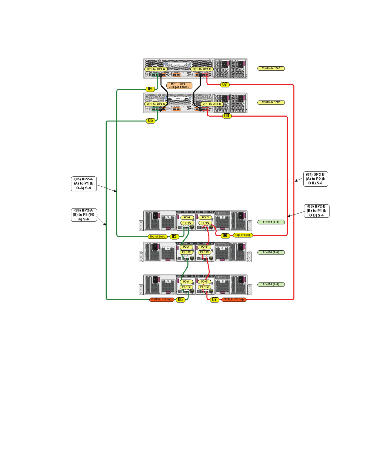
Figure 17 shows the connections to loop 2 between the EVA6400 controllers and disk enclosures 4,
5, and 6 (S-4, S-5, S-6).
Figure 17 Fibre Channel cabling for the EVA6400 loop 2 connections (rear view, top-mounted
controllers)
HP StorageWorks 6400/8400 Enterprise Virtual Array installation guide 75
Page 4

Figure 18 shows a fully cabled EVA6400 system with two controllers and six disk enclosures (2C6D).
Figure 18 Complete Fibre Channel cabling for the EVA6400 2C6D (rear view, top-mounted controller)
EVA6400/8400 cabling diagrams76
Page 5

Connecting EVA6400 controllers between the disk enclosures (2C18D)
Figure 19 shows the connections to loop 1 between the EVA6400 controllers and disk enclosures 1
through 9.
Figure 19 Fibre Channel cabling for the EVA6400 loop 1 connections (rear view, mid-mounted
controllers)
HP StorageWorks 6400/8400 Enterprise Virtual Array installation guide 77
Page 6

Figure 20 shows the connections to loop 2 between the EVA6400 controllers and disk enclosures 10
through 18.
Figure 20 Fibre Channel cabling for the EVA6400 loop 2 connections (rear view, mid-mounted
controllers)
EVA6400/8400 cabling diagrams78
Page 7

Figure 21 shows a fully cabled EVA6400 system with 2 controllers and 18 disk enclosures (2C18D).
Figure 21 Complete Fibre Channel cabling for EVA6400 2C18D (rear-view, mid-mounted)
HP StorageWorks 6400/8400 Enterprise Virtual Array installation guide 79
 Loading...