

Page 1

User and
Service
Guide
HP StorageWorks
Virtual Arrays
VA 7000 Family
Edition January 2005
Part number A6183-96008
Printed in U.S.A.
Page 2

Notice
Trademark Information
© Copyright 2000-2005 Hewlett-Packard
Development Company, L.P.
Hewlett-Packard Company makes no warranty of
any kind with regard to this material, including,
but not limited to, the implied warranties of
merchantability and fitness for a particular
purpose. Hewlett-Packard shall not be liable for
errors contained herein or for incidental or
consequential damages in connection with the
furnishing, performance, or use of this material.
This document contains proprietary information,
which is protected by copyright. No part of this
document may be photocopied, reproduced, or
translated into another language without the prior
written consent of Hewlett-Packard. The
information contained in this document is subject
to change without notice.
Format Conventions
WARNING Identifies a hazard that can cause
personal injury
Red Hat is a registered trademark of Red Hat Co.
C.A. UniCenter TNG is a registered trademark of
Computer Associates International, Inc.
Microsoft, Windows NT, and Windows 2000 are
registered trademarks of Microsoft Corporation
HP, HP-UX are a registered trademarks of HewlettPackard Company. CommandView, Secure
Manager, Business Copy, Auto Path are
trademarks of Hewlett-Packard Company
Adobe and Acrobat are trademarks of Adobe
Systems Inc.
Java and Java Virtual Machine are trademarks of
Sun Microsystems Inc.
NetWare is a trademark of Novell, Inc.
AIX is a registered trademark of International
Business Machines, Inc.
Caution Identifies a hazard that can cause
hardware or software damage
Note Identifies significant concepts or
operating instructions
this font - used for all text to be typed
verbatim: all commands, path names, file names,
and directory names also, text displayed on the
screen
<
this font
commands
this font - used for GUI menu options and screen
controls
2
> - used for variables used in
Page 3

Revision History
January 2002
Change Page
Added new supported non-native operating systems. 16
Added Operating Tips section. 57
Clarified explanation of redundancy groups 39
Expanded the procedure for upgrading DIMMs. 135
Added procedure for reducing the amount of cache. 136
March 2002
Change Page
Updated warranty information 7
Added information on new power supply model 102
Added information on new disk filler panel. 100
Added a procedure for adding a disk enclosure to a VA 7400. 132
April 2002
Change Page
Added new warning LED status display for updating battery firmware. 82
Added processor model to array controller description 24
Changed part numbers of replacement array enclosure controllers. 93
Added support for DS 2405 Disk System Multiple
Added information for identifying type of disk enclosure 92
Added DS 2405 Disk System part numbers to disk enclosure
replaceable parts.
Added step for setting FC Loop Speed switch on DS 2405 LCCs. 127
Added note on ensuring controller firmware is HP14 or later when
adding a DS 2405 Disk System to the array.
95
132
3
Page 4

July 2002
Change Page
Updated product information to include VA 7410. 13
Added VA 7410 back-end cabling. 33
Added "Data I/O Architecture" information. 52
Updated replaceable parts to include VA 7410 components 93
Updated procedure for adding a disk enclosure to include VA 7410. 132
January 2003
Change Page
Updated capacity and performance tables for VA 7110. 17
Added 73 GB 15K disk module and 146 GB disk module for support
26
on VA 7110 and 7410.
Updated Data Storage Process information 38
Updated configuration drawings. 59
Added VA 7110 LED displays. 81
Added VA 7110 controller to replaceable parts. 93
September 2003
Change Page
Updated VA 7110 DIMM configuration information to indicate that
512 MB is not supported.
14, 136
4
Page 5

March 2004
Change Page
Added a step to the controller installation procedure for recognizing
110
the new controller on HP-UX.
Added note regarding installing multiple disks. 132
Added information on replacing a controller in a single-controller
112
array.
January 2005
Change Page
Added Japanese power cord statement. 148
5
Page 6

About This Guide
This guide is intended for use by information technology (IT), service, and other personnel involved in
managing, operating, servicing, and upgrading the HP StorageWorks Virtual Array products. It is
organized into the following chapters:
Chapter 1. Product Overview Describes the features, controls, and operation of the
disk array.
Chapter 2. System Configurations Guidelines for designing array configurations for
different system requirements.
Chapter 3. Troubleshooting Instructions for isolating and solving common problems
that may occur during array operation
Chapter 4. Servicing & Upgrading Instructions for removing and replacing all field
replaceable units.
Chapter 5. Specifications & Regulatory
Statements
Product dimensions, weight, temperature and humidity
limits, shock and vibration limits, electrical and power
specifications, regulatory and safety statements, and
Declaration of Conformity.
Related Documents and Information
The following items contain information related to the installation, configuration, and management and
of the HP StorageWorks Virtual Array products:
—
HP StorageWorks Virtual Array 7000 Family Installation Guide
for installing and configuring the hardware and software components of the HP StorageWorks
Virtual Array products.
—
HP StorageWorks Virtual Array Family Rack Installation Guide
for installing the HP StorageWorks Virtual Array products into HP Rack System/E, HP System
racks, and Compaq 9000 racks.
—
HP StorageWorks CommandView SDM Installation and User Guide
use the HP StorageWorks CommandView SDM software and its associated utilities to configure,
manage, and diagnose problems with the array.
- includes step-by-step instructions
- includes step-by-step instructions
- describes how to install and
6
Page 7

Warranty Information
Standard Limited
Warranty
Warranty Contacts
U.S. and Canada
Current Support
Information
Preparing for a
Support Call
The HP SureStore Virtual Array Family standard warranty includes the following:
Two-year, same-day on-site warranty (parts and labor). Same-day response
equates to:
4-hour response, available normal business days (Monday-Friday) 8 am - 5 pm.
See the "Hewlett-Packard Hardware Limited Warranty" on page 8 for a complete
description of the standard warranty.
For hardware service and telephone support, contact:
An HP-authorized reseller or
HP Customer Support Center at 970-635-1000, 24 hours a day, 7 days a week,
including holidays
For the latest support information, visit the following web site:
http://www.hp.com/support/va7100
http://www.hp.com/support/va7400
http://www.hp.com/support/va7410
http://www.hp.com/support/va7110
If you must call for assistance, gathering the following information before placing
the call will expedite the support process:
— Product model name and number
— Product serial number
— Applicable error messages from system or diagnostics
— Operating system type and revision
— Applicable hardware driver revision levels (for example, the host
adapter driver)
7
Page 8

Hewlett-Packard Hardware Limited Warranty
HP warrants to you, the end-user Customer, that HP SureStore Virtual Array Family hardware
components and supplies will be free from defects in material and workmanship under normal use after
the date of purchase for
warranty period, HP or Authorized Reseller will, at its option, either repair or replace products that prove
to be defective. Replacement parts may be new or equivalent in performance to new.
Should HP or Authorized Reseller be unable to repair or replace the hardware or accessory within a
reasonable amount of time, Customer's alternate remedy will be a refund of the purchase price upon
return of the HP SureStore Virtual Array Family.
two years
. If HP or Authorized Reseller receives notice of such defects during the
Replacement Parts
Warranty
Items Not Covered
HP replacement parts assume the remaining warranty of the parts they replace.
Warranty life of a part is not extended by means of replacement.
Your HP SureStore Virtual Array Family warranty does not cover the following:
— Products purchased from anyone other than HP or an authorized
HP reseller
— Non-HP products installed by unauthorized entities
— Customer-installed third-party software
— Routine cleaning, or normal cosmetic and mechanical wear
— Damage caused by misuse, abuse, or neglect
— Damage caused by parts that were not manufactured or sold by
HP
— Damage caused when warranted parts were repaired or replaced
by an organization other than HP or by a service provider not
authorized by HP
8
Page 9

Warranty Information 6
Hewlett-Packard Hardware Limited Warranty 7
1 Product Overview 13
Supported Operating Systems 16
Array Management Software 16
Product Features 17
Controller Enclosure Components 19
Array Controller 24
Array Controller Filler Panel 26
Disk Drives 26
Disk Drive Filler Panels 28
Power Modules 28
Disk Enclosure Components 29
Link Controller Card (VA 7110/7400/7410 Only) 30
Disk Drives 30
Disk Drive Filler Panels 30
Power Modules 34
Operating the Power/Standby Switch 35
Power-On Self-Test 36
Shutdown 36
Data Storage Process 38
Virtual Array 38
Redundancy Groups 39
Performance Path 45
RAID Levels 47
Data I/O Architecture 52
Operating Tips 57
contents
9
Page 10

Automatic Hot Spare Setting Behavior 57
Install an Even Number of Disks in Each Redundancy Group 57
Auto Rebuild Behavior 58
2 System Configurations 59
Lowest Entry Point, Non-HA Minimum Configuration (VA 7100
only) 59
Lowest Entry Point, Non-HA Minimum Configuration (VA 7410) 60
Entry Level Non-Cluster With Path Redundancy (All VA arrays) 61
Entry Level Cluster with Path Redundancy High Availability (VA
7410) 62
Midrange Non-Cluster (All VA arrays) 63
Midrange Non-Cluster (VA 7410) 64
Midrange Non-Cluster with Full Storage Path Redundancy (All VA
Arrays) 65
Typical Non-Clustered with Path Redundancy (VA 7410) 66
Typical Clustered Configuration (All VA models) 67
Typical Clustered Configuration (VA 7410) 68
HP-UX MC Service Guard or Windows 2000 Cluster (All VA
arrays) 69
Highly Redundant Cluster (VA 7410) 70
Typical Highly Redundant Cluster (All VA models) 71
Typical Highly Redundant Cluster (VA 7410) 72
10 Contents
3 Troubleshooting 73
Troubleshooting Steps 74
Redundant FRUs 75
Array State & Status 76
Array Power-On Sequence 77
LED Status Indications 78
Tools for Checking Array State & Status 85
Array Controller Logs 86
Types of Array Controller Logs 86
Location of Array Controller Logs 86
Checking Array Controller Logs 87
EMS Hardware Monitors (HP-UX Only) 88
Page 11

4 Servicing & Upgrading 91
Field Replaceable Units (FRUs) 92
Identifying FRUs 92
Hot Swappable FRUs 97
Controller Enclosure Removal & Installation Procedures 98
Disk Drives 98
Disk Drive Filler Panels 100
Power Modules 102
Fiber Optic Cables 104
Gigabit Interface Converters 106
Array Controllers 107
Array Controller Filler Panels 115
Array Controller Batteries 117
Array Controller DIMMs 120
Midplane Assembly 122
Disk Enclosure Removal & Installation Procedures 125
Disk Drives 125
Disk Drive Filler Panels 125
Power Modules 125
Link Controller Cards (LCCs) 127
Midplane Assembly 131
Upgrading the Array 132
Increasing Storage Capacity 132
Upgrading Single to Dual Array Controllers 134
Upgrading Array Controller DIMMs 135
Upgrading Array Controller Firmware 137
Upgrading Link Controller Card Firmware 137
Upgrading Disk Firmware 138
5 Specifications & Regulatory Statements 139
Physical, Electrical & Environmental Specifications 140
Regulatory Statements 143
Contents 11
Page 12

12 Contents
Page 13

Product Overview
The HP StorageWorks Virtual Arrays are Fibre Channel disk arrays featuring
scalability, high performance, and advanced data protection. The VA 7000
Family includes the following models:
■ VA 7100 - an entry level array that includes a single controller enclosure
with up to 15 disks.
■ VA 7110 - a medium-capacity array that includes a controller enclosure
with up to 15 disks, and supports up to 2 additional external disk
enclosures each capable of housing 15 disks.
■ VA 7400 - a high-capacity array that includes a controller enclosure with
up to 15 disks, and supports up to 6 additional external disk enclosures
each capable of housing 15 disks.
■ VA 7410 - a higher-performance model of the VA 7400 that increases the
transfer speed between the array and disk enclosures to
2 Gbits/second, increases the amount of cache to 2 Gbytes, and adds
additional host and disk Fibre Channel ports.
1
Table 1 lists the VA 7000 Family configurations. Figure 1 illustrates the
enclosure configuration for the VA 7400/7410 products.
Both the controller enclosure and the disk enclosure can house up to 15 disk
modules in any combination of 18 GB, 36 GB, or 73 GB disk capacities. The
VA 7410 and VA 7110 also support 146 GB disk modules. The maximum
configuration for a VA 7400/7410 includes 105 disk drives with a total
capacity of 7.67 TB. The controller enclosure includes one or two array
controllers that use advanced storage technology to automatically select the
proper RAID level for storing data.
The array can be connected to one or more hosts, hubs, or switches via fiber
optic cables. Factory-racked products are shipped pre-configured in HP Rack
Product Overview 13
Page 14
System/E racks. Field-rackable products are supported in the racks listed in
Table 2.
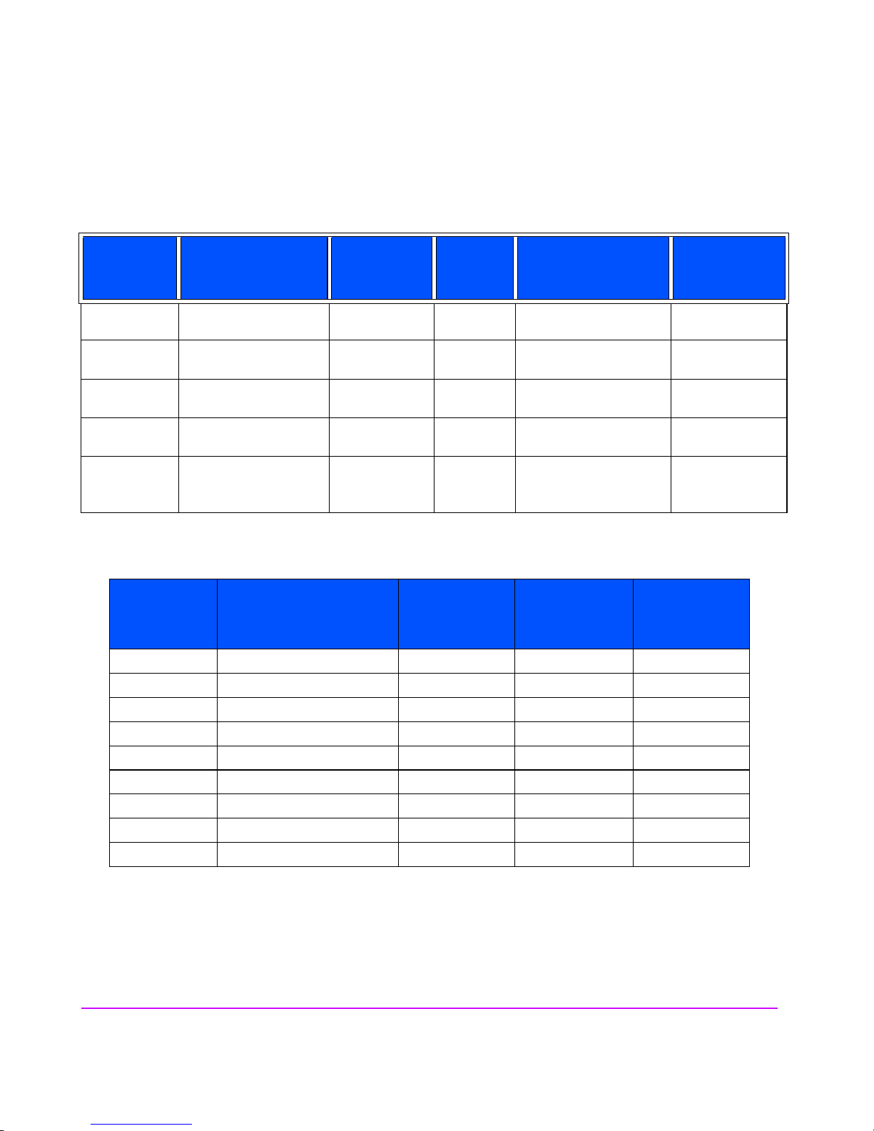
Table 1 Virtual Array Product Configurations
Model
Enclosure/
Configurations
VA 7100 Controller 1 4-15 1 or 2 array controllers
VA 7110 Controller 1 4-15 2 array controllers
VA 7400 Controller 1 10-15 2 array controllers
VA 7410 Controller 1 10-15 2 array controllers
VA 7110/
Disk 0-6 2-15 2 link controllers
7400/7410
a.See Table 25 on page 136 for valid DIMM configurations.
No. of
Enclosures
Disks
Per Encl.
Controller Cards
Per Encl.
1 Gbit/s
1 or 2 Gbit/s
1 or 2 Gbit/s
1 or 2 Gbit/s
7400: 1 Gbit/s
7410: 2 Gbit/s
Table 2 Virtual Array Supported Racks
Rack
Product No.
Rack Name
Height
meters/
EIA Units
No. of
EIA Units per
Array
1
Memory Per
Controller
(in MBytes)
256, 512,
or 1024
1024 or 2048
512 or 1024
1024 or 2048
No. of
Arrays
per Rack
a
N/A
2
J1500A HP Rack System/E41 1.96 m/ 41 U 3 13
J1501A HP Rack System/E33 1.60 m/ 33 U 3 11
J1502A HP Rack System/E25 1.25 m/ 25 U 3 8
E3660B HP System Rack 1.10 m/ 21 U 4 5
E3661B HP System Rack 1.60 m/ 32 U 4 8
E3662B HP System Rack 1.96 m/ 41 U 4 10
9142 Compaq 9000 Rack 2.0 m/ 42 U 3 14
9136 Compaq 9000 Rack 1.7 m/ 36 U 3 12
9122 Compaq 9000 Rack 1.1 m/ 22 U 3 7
1
HP Computer Cabinet requires a 1U filler panel to hide the mounting rails.
2
Does not include space that may be required for PDUs.
14 Product Overview
Page 15
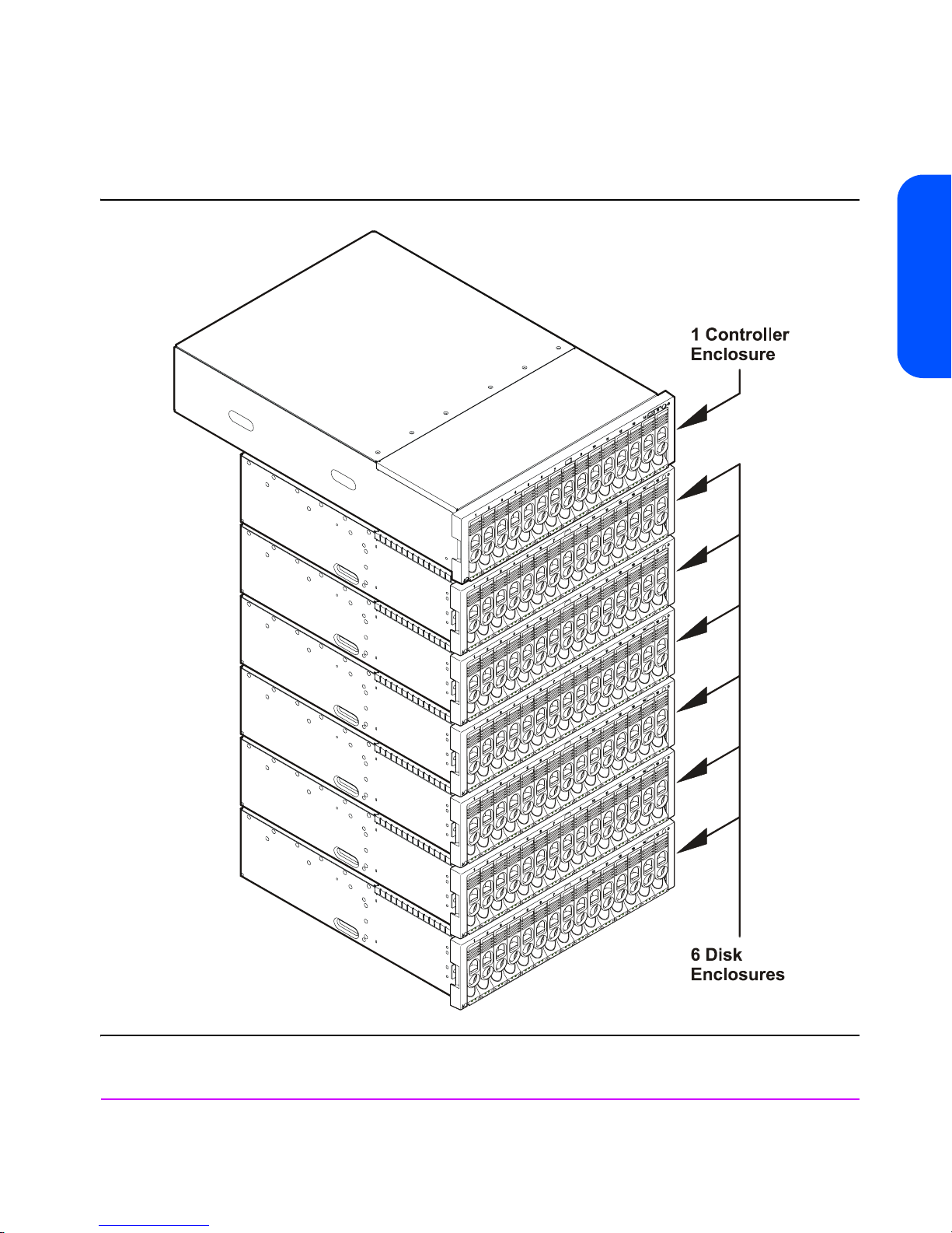
Figure 1 VA 7400/7410 Maximum Configuration
Product Overview
(2 Enclosures Supported on VA 7110)
Product Overview 15
Page 16

Supported Operating Systems
Native Operating Systems
The arrays are supported on the following native operating systems running
CommandView SDM software:
— HP-UX 11.x
— Windows NT 4.0
— Windows 2000
— Red Hat Linux
Non-Native Operating Systems
The following non-native operating systems are only supported using a
dedicated management station running CommandView SDM on one of the
native operating systems listed above:
— Sun Solaris
— IBM AIX
— NetWare
— MPE/iX (VA 7100 only)
Array Management Software
HP StorageWorks CommandView SDM (Storage Device Manager)
shipped with the arrays, is used to configure, manage, diagnose, and monitor
the performance of the array. The software runs on the native operating
systems and includes the following interfaces:
— CommandView Graphical User Interface (GUI)
— Command Line User Interface (CLUI)
— CommandView User Interface (CVUI)
16 Product Overview
software,
Page 17
Product Features
The arrays include the following features:
■ Scalability
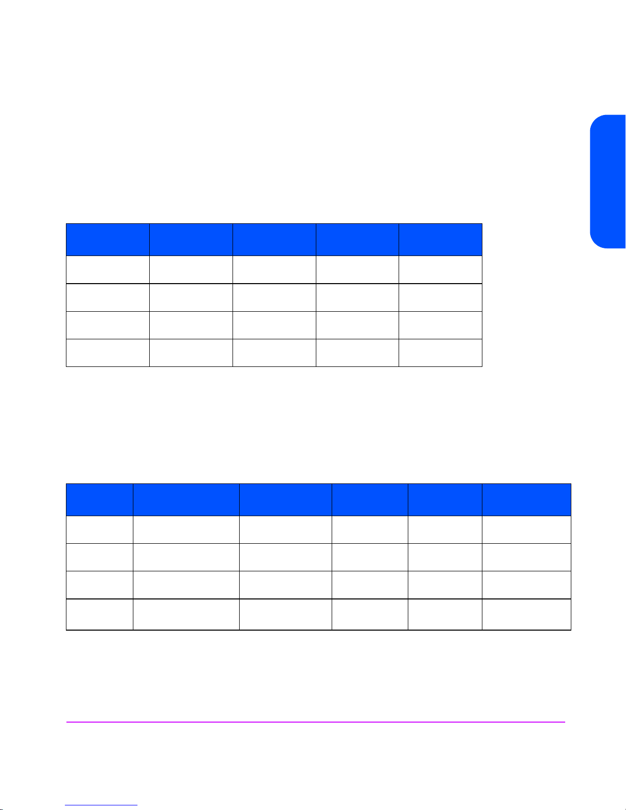
The capacities for the different products and disk modules are listed in Table 3.
Table 3 Data Storage Scalability
Product
No.
VA 7100 72 GB min
VA 7110 72 GB min
VA 7400 180 GB min
VA 7410 180 GB min
18 GB
Disk Module
270 GB max
810 GB max
1895 max
1895 max
■ High performance
— 10K rpm & 15K rpm disk drives
— 1 or 2 Gbit/s native Fibre Channel (host to controllers/controllers to
back-end)
— High performance read/write IOPS and cache hits. See Table 4
36 GB
Disk Module
144 GB min
540 GB max
144 GB min
1620 GB max
360 GB min
3780 GB max
360 GB min
3780 GB max
73 GB
Disk Module
292 GB min
1095 GB max
292 GB min
3285 GB max
730 GB min
7665 G B max
730 GB min
7665 G B max
Product Overview
146 GB
Disk Module
Not supported
584 GB min
6570 GB max
Not supported
1460 GB min
15,330 GB max
Table 4 Read/Write & Cache Performance
Product
No.
VA 7100 3,200 IOPS*
VA 7110 7150 IOPS*
VA 7400 8,000 IOPS*
VA 7410 11,000 IOPS*
Random
Reads
3,000 IOPS**
7100 IOPS**
7,500 IOPS**
11,000 IOPS**
Random
Writes
1,600 IOPS*
480 IOPS**
3500 IOPS*
1050 IOPS**
4,000 IOPS*
1,200 IOPS**
5,500 IOPS*
1,100 IOPS**
*RAID 1+0 only
**RAID 5DP only
Sequential
Reads
90 MB/s 45 MB/s 14,000 IOPS
160 MB/s 84 MB/s 15,500 IOPS
160 MB/s 80 MB/s 22,500 IOPS
330 MB/s 250 MB/s 30,000 IOPS
Sequential
Writes
Product Overview 17
Cache
Hits
Page 18

■ Advanced data protection
— RAID 5DP
— End-to-end data protection
— Mirrored ECC NV-SDRAM
1
— Dual battery cache backup
— Dual-ported native Fibre Channel disks
— Redundant, hot swappable field replaceable components – controllers,
power supplies, cooling, Fibre Channel components
1
Non-volatile synchronous dynamic random access memory/Error
Correction Code
18 Product Overview
Page 19
Controller Enclosure Components
Figure 2 through Figure 6 show the front and rear panel components of the VA
7000 Family controller enclosures.
Figure 2 VA 7100 Factory-Racked & Field-Racked Controller Enclosure (A/AZ)
Product Overview
3
4
21
56
7
89
10 11
12
14 13 15
1 - Power/Standby Switch 9 - HOST FC LEDs
2 - System LEDs 10 - Array Controller LEDs
3 - Disk Drive Slot No. 1 (of 15) 11 - RS-232 Connector
4 - Disk Drive 1 (of 15) - M/D1* 12 - Array Controller 2 - M/C2*
5 - Disk Drive LEDs 13 - Power Module 1 - M/P1*
6 - ESD Ground Receptacle 14 - AC Power Connector
7 - Array Controller 1- M/C1* 15 - Power Module LEDs
8 - HOST FC Connector - M/C1.H1* 16 - Power Module 2 - M/P2*
*Reference designator used in CommandView SDM
16
Product Overview 19
Page 20
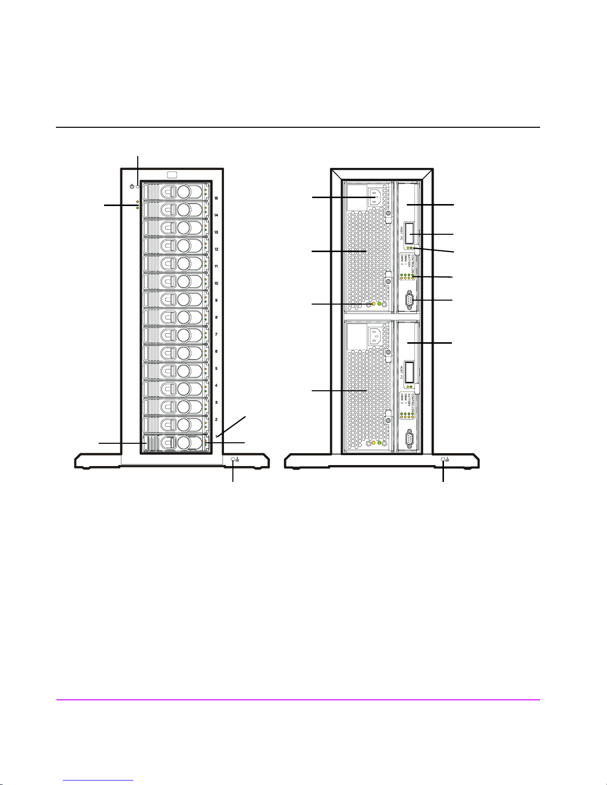
Figure 3 VA 7100 Controller Enclosure (D)
1
2
14
7
8
13
9
10
15
11
12
16
5
3
4
1 - Power/Standby Switch 10 - Array Controller LEDs
2 - System LEDs 11 - RS-232 Connector
3 - Disk Drive 1 (of 15) - M/D1* 12 - Array Controller 2 - M/C2*
4 - Disk Drive LEDs 13 - AC Power Connector
5 - Disk Drive Slot No. 1 (of 15) 14 - Power Module 1 - M/P1*
6 - Front ESD Ground Receptacle 15 - Power Module LEDs
7 - Array Controller 1 - M/C1* 16 - Power Module 2 - M/P2*
8 - HOST FC Connector - M/C1.H1* 17 - Rear ESD Ground Receptacle
9 - HOST FC LEDs
*Reference designator used in CommandView SDM
20 Product Overview
6 17
Page 21
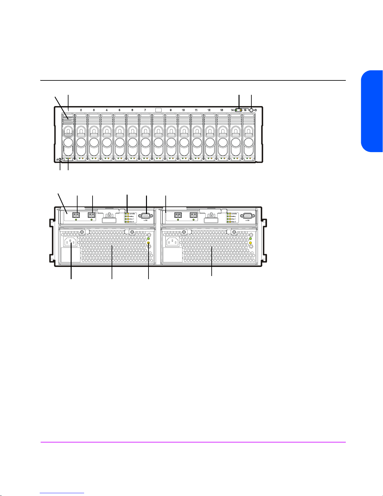
Figure 4 VA 7110 Controller Enclosure
3
4
65
789 1011
A
8
1
2
6
A
host 2disk 2
12
A
8
1
2
6
A
12
hostdisk
Product Overview
14
13
15
16
1 - Power/Standby Switch 9 - HOST FC Connector - M/C1.H1*
2 - System LEDs 10 - Array Controller LEDs
3 - Disk Drive Slot No. 1 (of 15) 11 - RS-232 Connector
4 - Disk Drive 1 (of 15) - M/D1* 12 - Array Controller 2 - M/C2*
5 - Disk Drive LEDs 13 - Power Module 1 - M/P1*
6 - ESD Ground Receptacle 14 - AC Power Connector
7 - Array Controller 1 - M/C1* 15 - Power Module LEDs
8 - DISK FC Connector and LED - M/C1.G1* 16 - Power Module 2 - M/P2*
*Reference designator used in CommandView SDM
Product Overview 21
Page 22
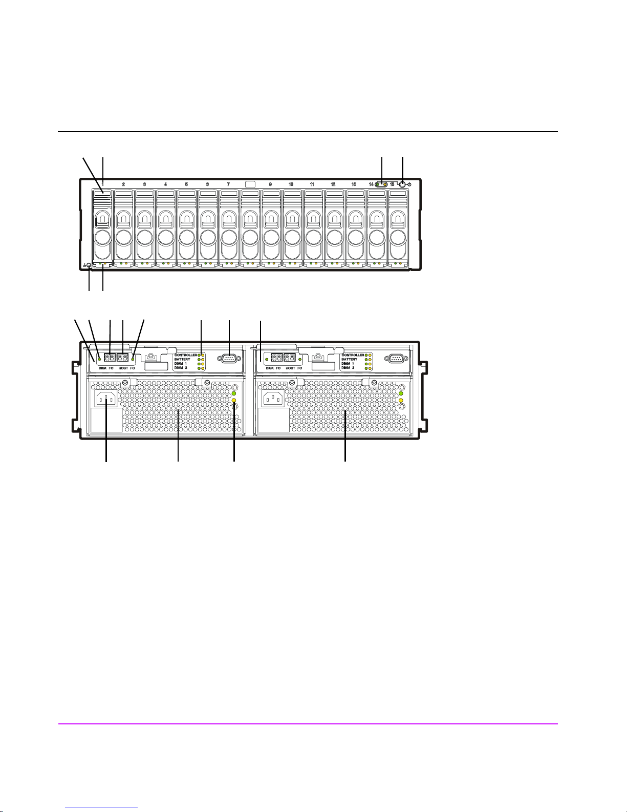
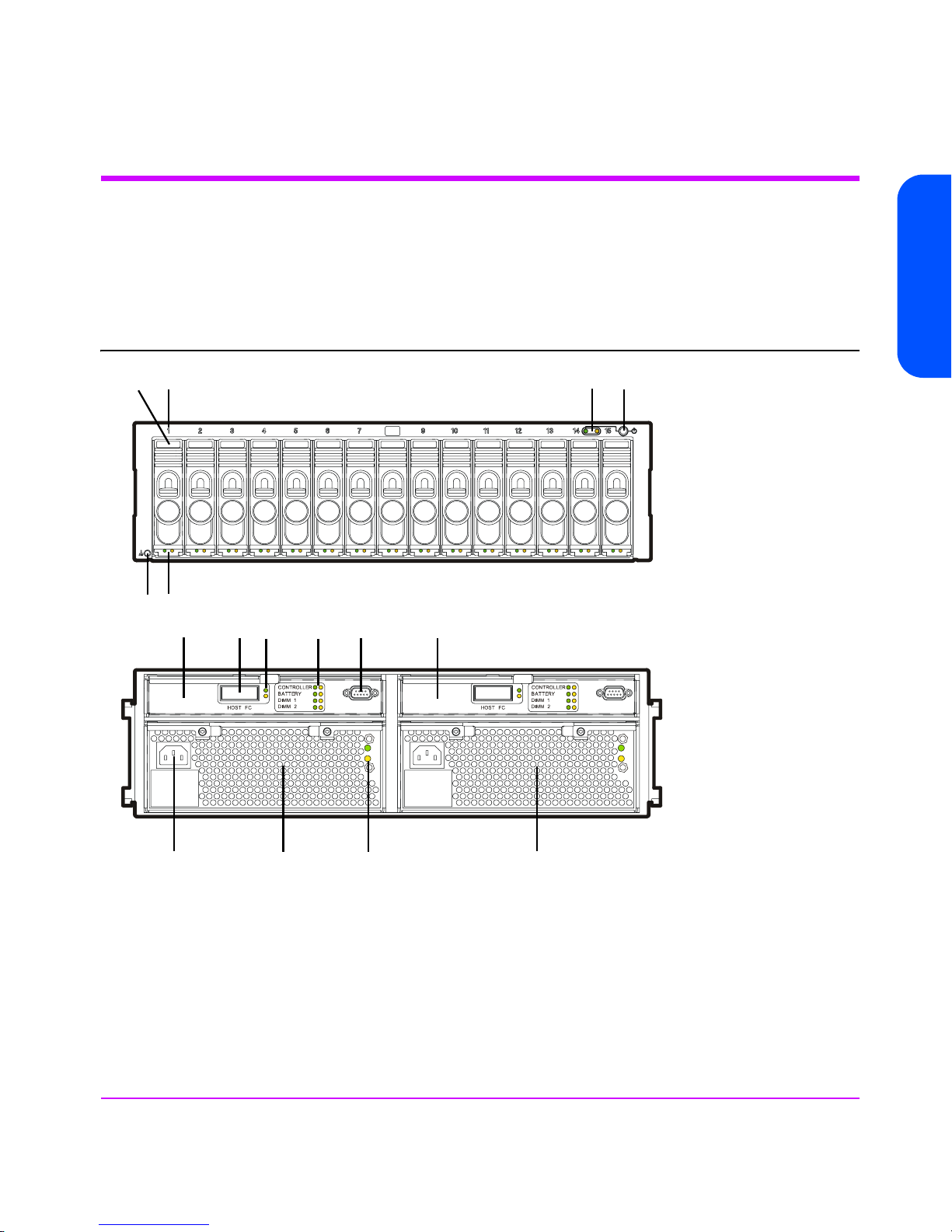
Figure 5 VA 7400 Controller Enclosure
4
65
8
3
9
1110
12 137
14
21
16 15 17 18
1 - Power/Standby Switch 10 - HOST FC Connector - M/C1.H1*
2 - System LEDs 11 - HOST FC LED
3 - Disk Drive Slot No. 1 (of 15) 12 - Array Controller LEDs
4 - Disk Drive 1 (of 15) - M/D1* 13 - RS-232 Connector
5 - Disk Drive LEDs 14 - Array Controller 2 - M/C2*
6 - ESD Ground Receptacle 15 - Power Module 1 - M/P1*
7 - Array Controller 1 - M/C1* 16 - AC Power Connector
8 - DISK FC LED 17 - Power Module LEDs
9 - DISK FC Connector - M/C1.G1* 18 - Power Module 2 - M/P2*
*Reference designator used in CommandView SDM
22 Product Overview
Page 23
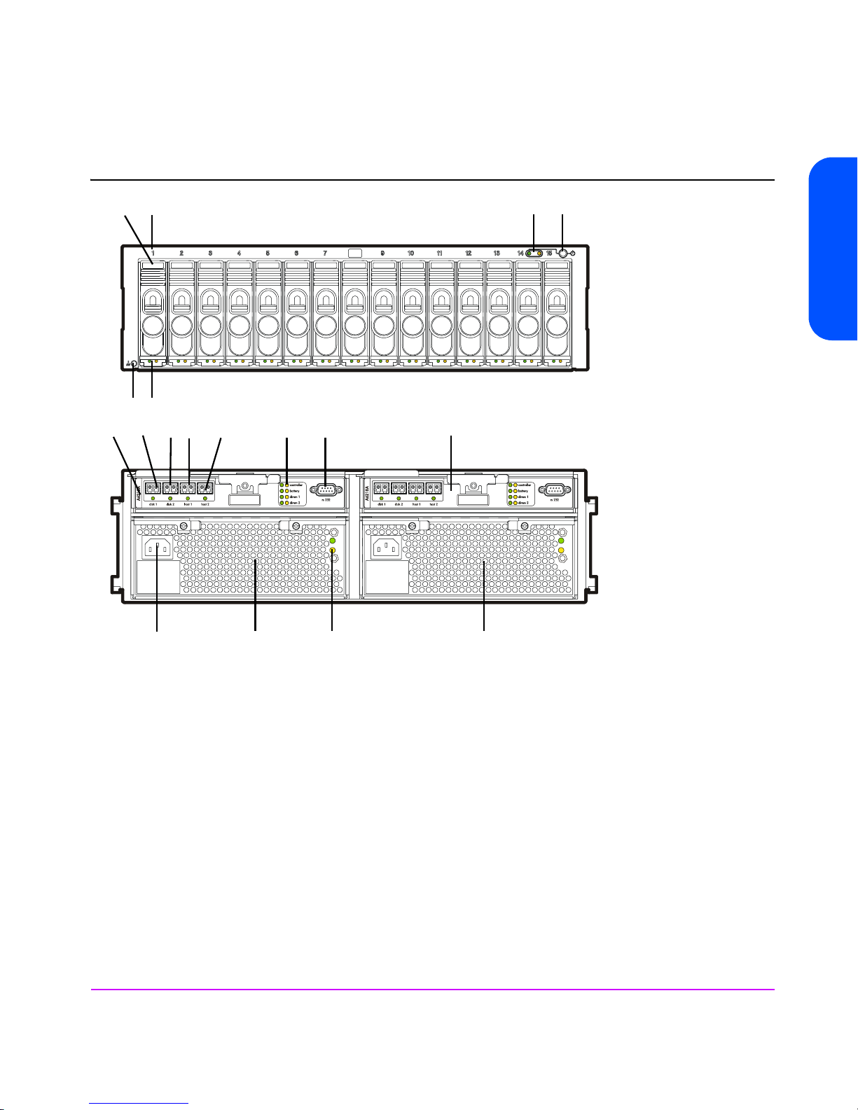
Figure 6 VA 7410 Controller Enclosure (A/AZ)
4
65
3
9
8
10
11
12
137
14
21
Product Overview
16 15 17 18
1 - Power/Standby Switch 10 - HOST 1 FC Port and LED (M/C1.H1*)
2 - System LEDs 11 - HOST 2 FC Port and LED (M/C1.H2*)
3 - Disk Drive Slot No. 1 (of 15) 12 - Array Controller LEDs
4 - Disk Drive 1 (of 15) (M/D1*) 13 - RS-232 Connector
5 - Disk Drive LEDs 14 - Array Controller 2 (M/C2*)
6 - ESD Ground Receptacle 15 - Power Module 1 (M/P1*)
7 - Array Controller 1 (M/C1*) 16 - AC Power Connector
8 - DISK 1 FC Port and LED (M/C1.J1*) 17 - Power Module LEDs
9 - DISK 2 FC Port and LED (M/C1.J2*) 18 - Power Module 2 (M/P2*)
*Reference designator used in CommandView SDM
Product Overview 23
Page 24

Array Controller
The array controller contains the intelligence and functionality required to
manage the operation of the array. Its functions include:
■ Implementing HP
AutoRAID
™
technology to ensure optimum performance
and cost-efficient data storage.
■ Managing all communication between the host and the disk drives via one
(single array controller) or two (dual array controller) Fibre Channel
arbitrated loops.
■ Maintaining data integrity.
■ Rebuilding the array in the event of a disk failure.
■ Monitoring the operation of all hardware components, including the array
controller itself.
In a dual array controller configuration, two controllers provide redundant
paths to array data. Dual array controllers operate together in active-active
concurrent access mode, allowing a possible increase in I/O performance
while providing data redundancy. In active-active mode, memory maps on
both controllers are constantly and simultaneously updated. By maintaining a
mirror image of the maps, the second controller can take over immediately if
the first controller fails.
Each array controller card includes the following components:
— 1 or 2 Dual Inline Memory Modules (DIMMs)
— 1 Battery
— VA 7100 Only - 1 Gigabit Interface Converter (GBIC)
— Motorola 8240 PowerPC processor (VA 7100 and VA 7400)
— IBM 440 processor (VA 7410)
VA 7410 Fibre Channel Ports
The VA 7410 enhances flexibility, availability, and performance by adding an
additional host port to each controller. This increases the number of paths from
the host systems to the array. The VA 7410 also adds a second disk port to
each controller, resulting in four back-end ports. This creates two independent
Fibre Channel loops between the controller enclosure and the disk enclosures.
Back-end performance is enhanced by distributing the disks across both loops.
24 Product Overview
Page 25

DIMMs
Each array controller includes one or two ECC SDRAM DIMMs that are battery
backed up and mirrored with the dual controller. This memory is used for the
read and write cache, and for the virtualization data structures. These data
structures provide the logical-to-physical mapping required for virtualization
and are vital to the operation of the array. Without these data structures, all
data in the array is inaccessible.
Note The DIMMs are a critical component in maintaining correct
operation of the array. Use extreme caution when replacing or
modifying the DIMM configuration.
Table 25 on page 136 shows the valid configuration of DIMMs for each
controller cache size. In a dual controller configuration, both controllers must
have the same cache size.
Battery
Note The array controller battery is a critical component in
maintaining the virtualization data structures during a power
loss when the array has not successfully completed a shutdown.
Exhausting the battery power in this state may result in data loss.
Product Overview
Each array controller includes a Lithium Ion-type battery with a built-in
microprocessor. The battery provides backup power to the DIMMs in the event
of a power failure or if array power is switched off. The batteries provide
power for minimum of 84 hours. If line power is lost, the green BATTERY LED
will flash with a 5% duty cycle while powering the DIMMs. A fully charged
battery will maintain DIMM memory contents for a minimum of three days.
(The three-day specification includes derating for battery life, temperature, and
voltage.) If the battery loses its charge, or if it is removed from the controller,
the DIMMs will not be powered and memory maps will be lost.
Battery Status. The controller constantly interrogates the battery for its status. If
the battery cannot maintain memory contents for a minimum of three days, a
warning will notify the operator to replace the battery. Every six months, the
battery performs a self-test to determine its charge status. Then it is fully
discharged and fully recharged to optimize battery life. This action is not
indicated by software or LEDs. In a dual controller configuration, only one
battery at a time is discharged and recharged. If the battery becomes
discharged during normal operation, the green BATTERY LED will turn off and
the amber BATTERY LED will turn on. If the battery has low charge during a
Product Overview 25
Page 26

power-on self-test, the self-test will halt until the battery is charged to a
minimum operating level.
Battery Life. Many factors affect battery life, including length of storage time,
length of operating time, storage temperature, and operating temperature. A
battery should be replaced if the BATTERY LEDs or the software indicate a
battery has diminished storage capacity.
GBIC (VA 7100 Only)
A Gigabit Interface Converter (GBIC) is connected to the HOST FC connector
on the VA 7100 array controller card. It functions as a fiber optic transceiver,
converting data from an electrical to an optical signal in transmit mode, or
from an optical signal to an electrical signal in receive mode. On the
VA 7400/7410 array controller card, GBIC circuitry is integrated.
Array Controller Filler Panel
An array controller filler panel is used to fill an empty slot in place of an array
controller. A filler panel must be installed to maintain proper airflow in the
array enclosure.
Caution Do not operate the array for more than 5 minutes with an array
controller or filler panel removed. Either an array controller or a
filler panel must be installed in the slot to maintain proper
airflow in the array enclosure. If necessary, the foam in the
replacement array controller packaging can be used to
temporarily fill the array controller slot.
Disk Drives
Both the controller and disk enclosures contain disk drives. Disk drives, or
“disks”, provide the storage medium for the virtual array. Four types of native
Fibre Channel disk drives are supported in the array; disk capacities can be
homogeneous, or can be mixed within the array:
— 18 GB 15K rpm
— 36 GB 10K rpm
— 36 GB 15K rpm
— 73 GB 10K rpm
— 73 GB 15K rpm (VA 7110 and VA 7410 only)
— 146 GB 10K rpm (VA 7110 and VA 7410 only)
26 Product Overview
Page 27

A new disk can be added at any time, even while the array is operating.
When a disk is replaced, the array applies power to the disk in a controlled
manner to eliminate power stresses. The array controller will recognize that a
new disk has been added and, if the Auto Include feature is enabled, will
include the disk in the array configuration automatically. However, to make the
additional capacity available to the host, a new logical drive must be created
and configured into the operating system.
A label on the disk drive provides the following information:
— Capacity in gigabytes: 18G, 36G, 73G, or 146G
— Interface: FC (Fibre Channel)
— Rotational speed in revolutions per minute: 10K or 15K
Note A red zero (0) on the capacity label distinguishes a disk drive
filler panel from a disk drive.
Image Disks
When the array is formatted, the array controller selects two disks as image
disks. On the VA 7410 a third disk is identified as a backup in the event one of
the primary image disks fails. Because it is not possible to predict which disks
will be selected as the image disks, the management software must be used to
determine which disks have been selected.
Product Overview
The image disks serve two functions:
■ The image disks have space reserved for copies, or “images”, of the write
cache and virtualization data structures stored in the controller NVRAM.
During a shutdown, a complete copy of the NVRAM is stored on both
image disks. If the maps are lost, they can be restored from the image
disks.
■ When resiliency map settings are set to the factory default (Normal
Resiliency), changes to the maps, which have occurred since the last
shutdown, are updated every 4 seconds on the image disks.
Note A shutdown makes the disk set independent of its controller.
Because all of the necessary mapping information is on the
image disks, it is possible to install a new controller or move the
entire disk set to another controller. The new controller will
determine that it has a new disk set, and will logically attach
itself to those disks.
Product Overview 27
Page 28

If an image disk fails on the VA 7100 or VA 7400, the array will operate with
a single image disk until the failed disk is replaced. If an image disk fails on
the VA 7410, the backup image disk will be used, maintaining image disk
redundancy. When the original failed image disk is replaced, it will be
assigned the role of backup image disk.
Disk Drive Filler Panels
Disk drive filler panels are used in both the controller and disk enclosures to fill
empty slots in place of disk drives. A filler panel must be installed to maintain
proper cooling in the enclosure.
Caution Do not operate the array for more than 5 minutes with a disk
Power Modules
The controller enclosure is shipped with two fully redundant power modules.
Each power module contains:
■ An autoranging power supply that converts ac input power to dc output
power for use by the other array components. The power supplies share the
power load under non-fault conditions. If one power supply fails, the other
supply delivers the entire load to maintain power for the array. Each power
supply uses a separate power cord. Both power supplies can be plugged
into a common ac power source, or each supply can be plugged into a
separate ac circuit to provide power source redundancy.
drive or filler panel removed. Either a disk drive or filler panel
must be installed in the slot to maintain proper airflow and avoid
overheating.
■ Two internal blowers, which provide airflow and maintain the proper
operating temperature within the enclosure. If a blower fails, a fault will
occur. The other power module will continue to operate and its blowers will
continue to cool the enclosure. Even if a power supply fails, both of the
blowers within the power module will continue to operate; dc power for the
blowers is distributed from the midplane.
28 Product Overview
Page 29
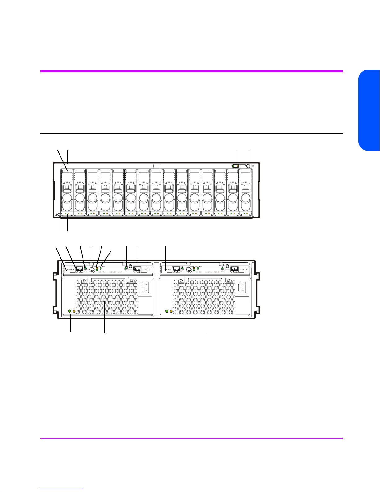
Disk Enclosure Components
Figure 7 shows the front and rear panel components of the disk enclosure
connected to the VA 7400/7410 controller enclosure. Both DS 2400 and
DS 2405 Disk Systems are used as disk enclosures on the VA 7400/7410.
Figure 7 VA 7110/7400/7410 Disk Enclosure (A/AZ)
Product Overview
4
123
56
10
11
9
8
7
17
12
13
14
16 15 18
1 - Power/Standby Switch 10 - ADDRESS Switch
2 - System LEDs 11 - LCC LEDs
3 - Disk Drive Slot No. 1 (of 15) 12 - PORT 1 LINK ACTIVE LED
4 - Disk Drive 1 (of 15) - JAn/D1* 13 - PORT 1 FC-AL Connector - JAn/C1.J2*
5 - Disk Drive LEDs 14 - Link Controller Card 2 - JAn/C2*
6 - ESD Ground Receptacle 15 - Power Module 1 - JAn/P1*
7 - Link Controller Card 1 - JAn/C1* 16 - Power Module LEDs
8 - PORT 0 FC-AL Connector - JAn/C1.J1* 17 - 2G LED (DS 2405 Disk System only)
9 - PORT 0 LINK ACTIVE LED 18 - Power Module 2 - JAn/P2*
*Reference designator used in CommandView SDM
Product Overview 29
Page 30

Link Controller Card (VA 7110/7400/7410 Only)
The link controller card (LCC) functions as a fiber optic transceiver for the disk
enclosure. It allows up to six disk enclosures to be connected to the controller
enclosure. Each LCC includes a Fibre Channel address switch, used to set the
Fibre Channel loop address of the card. Each disk enclosure must have a
unique address and both LCCs in a disk enclosure must be set to the same
address. For cabling connections and switch settings, see Figure 8 for the
VA 7110, Figure 9 for the VA 7400, and Figure 10 for the VA 7410.
The LCC also monitors the operation of the disk enclosure and provides status
information to the array controller. This includes what disks are present and
their status, power supply status, and notification if the enclosure operating
temperature has exceeded its limits.
Disk Drives
Up to 15 disks can be installed in each disk enclosure. The controller enclosure
and the disk enclosure both use the same disk drives. See "Disk Drives" on
page 26.
Image Disks
The image disks can be located in either the controller enclosure or the disk
enclosure. See "Image Disks" on page 27.
Disk Drive Filler Panels
The controller enclosure and the disk enclosure both use the same disk drive
filler panels. See "Disk Drive Filler Panels" on page 28.
30 Product Overview
Page 31

Figure 8 VA 7110 Back-End Fiber Optic Cabling & Addressing (2 Disk Enclosures)
CONTROLLER
Product Overview
ADDRESS4
3
LCC
5
ACTIVE
6
2
PORT 0 PORT 1
ADDRESS4
3
5
6
2
1
0
ADDRESS4
3
5
6
2
1
0
A6214-60001
PORT 0 PORT 1
A6214-60001
LCC
LINK
ACTIVE
1
0
FC-AL 100MB/s FC-AL 100MB/s
LINK
ACTIVE
FAULT
JBOD 1
ADDRESS4
3
5
LCC
ACTIVE
6
2
LCC
LINK
ACTIVE
1
0
FC-AL 100MB/s FC-AL 100MB/s
LINK
FAULT
ACTIVE
JBOD 2
ADDRESS4
3
LCC
5
ACTIVE
6
2
PORT 0 PORT 1
A6214-60001
PORT 0 PORT 1
A6214-60001
LCC
LINK
ACTIVE
1
0
FC-AL 100MB/s FC-AL 100MB/s
ADDRESS4
3
5
6
2
LINK
ACTIVE
1
0
FC-AL 100MB/s FC-AL 100MB/s
LINK
ACTIVE
FAULT
LCC
ACTIVE
LCC
LINK
FAULT
ACTIVE
ADDRESS4
3
5
6
2
1
0
4
ADDRESS
3
5
6
2
1
0
Product Overview 31
Page 32

Figure 9 VA 7400 Back-End Fiber Optic Cabling & Addressing (6 Disk Enclosures)
CONTROLLER
4
ADDRESS
3
LCC
5
ACTIVE
2
6
PORT 0 PORT 1
4
ADDRESS
3
5
6
2
1
0
ADDRESS4
3
5
6
2
1
0
4
ADDRESS
3
5
6
2
1
0
ADDRESS4
3
5
6
2
1
0
ADDRESS4
3
5
6
2
1
0
A6214-60001
PORT 0 PORT 1
A6214-60001
PORT 0 PORT 1
A6214-60001
PORT 0 PORT 1
A6214-60001
PORT 0 PORT 1
A6214-60001
LCC
LINK
ACTIVE
1
0
FC-AL 100MB/s FC-AL 100MB/s
LINK
ACTIVE
FAULT
JBOD 0
ADDRESS4
3
5
LCC
ACTIVE
6
2
LCC
LINK
ACTIVE
1
0
FC-AL 100MB/s FC-AL 100MB/s
LINK
FAULT
ACTIVE
JBOD 1
ADDRESS4
3
5
LCC
ACTIVE
2
6
LINK
ACTIVE
1
0
FC-AL 100MB/s FC-AL 100MB/s
LINK
LCC
FAULT
ACTIVE
JBOD 2
ADDRESS4
3
5
LCC
ACTIVE
6
2
LINK
ACTIVE
1
0
FC-AL 100MB/s FC-AL 100MB/s
LINK
LCC
FAULT
ACTIVE
JBOD 3
ADDRESS4
3
5
LCC
ACTIVE
2
6
LINK
ACTIVE
1
0
FC-AL 100MB/s FC-AL 100MB/s
LINK
LCC
ACTIVE
FAULT
JBOD 4
4
ADDRESS
3
LCC
5
ACTIVE
2
6
PORT 0 PORT 1
A6214-60001
PORT 0 PORT 1
A6214-60001
PORT 0 PORT 1
A6214-60001
PORT 0 PORT 1
A6214-60001
PORT 0 PORT 1
A6214-60001
LCC
LINK
ACTIVE
1
0
FC-AL 100MB/s FC-AL 100MB/s
ADDRESS4
3
5
6
2
LINK
ACTIVE
1
0
FC-AL 100MB/s FC-AL 100MB/s
ADDRESS4
3
5
2
6
LINK
ACTIVE
1
0
FC-AL 100MB/s FC-AL 100MB/s
ADDRESS4
3
5
6
2
LINK
ACTIVE
1
0
FC-AL 100MB/s FC-AL 100MB/s
ADDRESS4
3
5
2
6
LINK
ACTIVE
1
0
FC-AL 100MB/s FC-AL 100MB/s
LINK
ACTIVE
FAULT
LCC
ACTIVE
LCC
LINK
FAULT
ACTIVE
LCC
ACTIVE
LINK
LCC
FAULT
ACTIVE
LCC
ACTIVE
LINK
LCC
FAULT
ACTIVE
LCC
ACTIVE
LINK
LCC
ACTIVE
FAULT
ADDRESS4
3
5
6
2
1
0
4
ADDRESS
3
5
6
2
1
0
ADDRESS4
3
5
6
2
1
0
4
ADDRESS
3
5
6
2
1
0
ADDRESS4
3
5
6
2
1
0
ADDRESS4
3
LCC
5
ACTIVE
2
6
PORT 0 PORT 1
LINK
LCC
FAULT
ACTIVE
1
A6214-60001
0
ADDRESS4
3
5
6
2
1
0
FC-AL 100MB/s FC-AL 100MB/s
JBOD 5
32 Product Overview
ADDRESS4
3
LCC
5
ACTIVE
2
6
LINK
ACTIVE
PORT 0 PORT 1
LINK
ACTIVE
1
A6214-60001
0
FC-AL 100MB/s FC-AL 100MB/s
LINK
LCC
FAULT
ACTIVE
ADDRESS4
3
5
6
2
1
0
Page 33

Figure 10 VA 7410 Back-End Fiber Optic Cabling & Addressing (6 Disk Enclosures)
Product Overview
FC Loop 1
FC Loop 2
Product Overview 33
Page 34

Power Modules
The disk enclosure is shipped with two fully redundant power modules. Each
power module contains:
■ An autoranging power supply that converts ac input power to dc output
power for use by the other array components. The power supplies share the
power load under non-fault conditions. If one power supply fails, the other
supply delivers the entire load to maintain power for the array. Each power
supply uses a separate power cord. Both power supplies can be plugged
into a common power source, or each supply can be plugged into a
separate circuit to provide power source redundancy.
■ One internal blower, which provides airflow and maintains the proper
operating temperature within the array enclosure. If the blower fails, a fault
will occur. The other power module will continue to operate and its blower
will continue to cool the enclosure. Even if a power supply fails, the blower
within the power module will continue to operate; dc power for the blower
is distributed from the midplane.
34 Product Overview
Page 35

Operating the Power/Standby Switch
When the power/standby switch is in the “power” position, ac power is
applied to the primary and secondary sides of the power supplies in the power
module and all of the dc circuits in the array are active. When the power/
standby switch is in the “standby” position, ac power is only applied to the
primary side of the power supplies; all of the dc circuits in the array are
disabled.
To switch power on, push in the power/standby switch to the “power” position.
See Figure 11.To switch power to standby, push in the power/standby switch
then release it to the “standby” position.
Caution If it is necessary to completely remove power from the array, you
must unplug both power cords from the ac power connectors on
the array rear panel.
Figure 11 Operating the Power/Standby Switch
Product Overview
Product Overview 35
Page 36

Power-On Self-Test
Shutdown
Immediately after the array is powered on, the controller enclosure and disk
enclosures (VA 7400/7410 only) perform a power-on self-test.
During a power-on self-test, you will see the following front panel activity:
■ The system power/activity LED turns on solid green.
■ The disk drive activity LEDs flash while the controller establishes
communication with the drives, then two LEDs at a time turn on solid green,
one from the lower disk drive slots (1-8) and one from the upper disk drive
slots (9-15), while the associated drives spin up.
When the power-on self-test completes successfully:
■ All LEDs on the front panel should be solid green.
The coordinated shutdown process is used to take the array offline. The
primary function of shutdown is to copy the contents of the NVRAM to the
image disks. This protects the array against data loss if a battery fails in the
absence of ac power. In the shutdown state, the array can still respond to
management commands from the host, but the host cannot access any of the
data in the array.
36 Product Overview
During shutdown, the array will use the contents of the controller NVRAM if
valid. For a dual controller configuration only a single NVRAM image is
required to be valid.
Note If the NVRAM image is not valid the array will enter an error
state. The configuration information and the write cache have
been lost. Access to the data requires a Recover process.
Recovery will attempt to recover the configuration information
from the data disks. The contents of the write cache are not
recoverable.
A shutdown is automatically initiated in two ways:
■ By moving the power/standby switch to the standby position.
■ Using the array management software.
Page 37

Note Using software to perform a shutdown is the preferred method
because confirmation of a successful shutdown is reported to the
operator.
If the power fails or if you unplug the power cords without performing a
shutdown, the following sequence will occur when the array is powered on
again:
1 The array will attempt to retrieve the maps from cache and determine if they
are valid.
2 If the maps are not valid, the array will retrieve the maps from the image
disks.
Note If power to the array is lost by any means other than by moving
the power/standby switch to the standby position, the array will
not have time to perform a successful shutdown. In this case, a
fully charged battery can sustain NVSDRAM contents for 3
days.
Product Overview
Product Overview 37
Page 38

Data Storage Process
Virtual Array
The term “Virtual Array” refers to the way the array manages the disks as a
pool of data storage blocks instead of whole physical disks. Like other
virtualization within computer systems, this virtualization greatly simplifies the
management of the array. Internally, the array uses sophisticated data
structures to manage the logical-to-physical address translation. These data
structures, often referred to as the “maps”, are key to the operation of the array.
See Figure 12.
Administrators’ manage the capacity of the array using Redundancy Groups
and LUNs. Each disk belongs to a predefined Redundancy Group, and a LUN
is created from the capacity of a Redundancy Group. This is similar to
traditional arrays. The virtualization eliminates the need to manage the lower
level details. Redundancy Groups can be constructed from any number or
capacity of supported disks. Any number of disks can be added to a
Redundancy Group at any time. LUNs can be of any size up to the available
capacity of a RAID Group, or created and deleted without the knowledge of
the underlying physical disk layout. The VA 7100 supports up to 128 LUNs;
the VA 7400/7410 support up to 1024 LUNs.
38 Product Overview
Page 39

Figure 12 Virtual Data Storage
Product Overview
Host
LUN 1
LUN 2
Cache
Maps
Storage
Pool
Redundancy Groups
Array physical capacity is divided into Redundancy Groups. A Redundancy
Group (RG) can be thought of as an independent array. Each RG has its own
set of disks, active hot spare, and controller. LUNs are created from capacity
within a single RG. LUNs can be accessed simultaneously through either
controller.
Multiple redundancy groups provide the following benefits:
■ Fault isolation. Because each redundancy group has its own resources, a
■ Performance management. Applications can be assigned to different RGs,
■ Greater configurability. Each RG can be constructed from different classes
disk failure in one RG will not impact the other RG. This effectively
increases the data availability of the array.
thus isolating their performance impact on each other.
of disks. As an example, one RG could be constructed from a few, small,
Product Overview 39
Page 40

high-performance disks, and the other RG from large, slower, highcapacity disks.
The VA 7100 and VA 7400/7410 differ in their implementation of
redundancy groups.
VA 7100/7110 Redundancy Group
The VA 7100 and VA 7110 each have one redundancy group (RG1). See
Figure 13 and Figure 14. All the disks in the array belong to RG1. LUNs
created from RG1 are available through both controllers (in a dual controller
configuration).
There are two internal fibre channel loops, one from each controller. The Fibre
channel disks are dual ported; each fibre channel port is connected to a
different controller. The controllers are connected via an internal highperformance bus, which allows the LUNs to be accessed through both
controllers, and for loop or disk failover communication.
Figure 13 VA 7100 Redundancy Group
Host
Controller 1
RG1
D1
RG1
N-Way Bus
...
D2
RG1
D15
RG1
Host
Controller 2
RG1
40 Product Overview
Page 41

Figure 14 VA 7110 Redundancy Group
Product Overview
Host
Controller 1
Disk
L
C
C
1
RG1
RG1
D1
RG1
D1
N-Way Bus
D2
RG1
...
D2
RG1
...
RG1
D15
RG1
D15
Host
Controller 2
RG1
Disk
L
C
C
2
L
C
C
1
D1
RG1
RG1
D2
...
D15
RG1
L
C
C
2
Product Overview 41
Page 42

VA 7400/7410 Redundancy Groups
The VA 7400 and VA 7410 have two redundancy groups (RG1 and RG2). See
Figure 15 and Figure 16.
■ Controller 1 manages Redundancy Group 1 (RG1), which consists of all
disks in odd numbered slots (D1, D3, D5, D7, D9, D11, D13, D15) in the
controller enclosure, and in all disk enclosures (JA0-JA5).
■ Controller 2 manages Redundancy Group 2 (RG2), which consists of all
disks in even numbered slots (D2, D4, D6, D8, D10, D12, D14) in the
controller enclosure, and in all disk enclosures (JA0-JA5).
On the VA 7410, Redundancy Group are independent of both back-end FC
loops. Management of the redundancy group disks is independent of which
disk enclosure LCC the array controller is connected to. For example, array
controller 1 can be connected to LCC 1 or LCC 2 and it will still manage the
disks in the odd numbered slots.
The array controllers are connected via an internal N-Way bus, which used for
controller-to-controller communication and loop failover.
42 Product Overview
Page 43

Figure 15 VA 7400 Redundancy Groups
Product Overview
Host
Controller 1
Disk
L
C
C
1
RG1
RG1
D1
RG1
D1
N-Way Bus
D2
RG2
...
D2
RG2
...
RG1
D15
RG1
D15
Host
Controller 2
RG2
Disk
L
C
C
2
L
C
C
1
D1
RG1
D2
RG2
...
D15
RG1
L
C
C
2
. . .
L
C
C
1
D1
RG1
D2
RG2
...
D15
RG1
L
C
C
2
Product Overview 43
Page 44

Figure 16 VA 7410 Redundancy Groups
D1
N-Way Bus
RG2
L
C
C
2
D2
...
L
C
C
1
D15
RG1
D1
RG1
Host 2Host 1
Controller 2
RG2
Disk 1 Disk 2
...
D2
RG2
D15
RG1
L
C
C
2
Host 2Host 1
Controller 1
RG1
Disk 1 Disk 2
L
C
C
1
D1
RG1
D2
RG2
...
RG1
D15
RG1
L
C
C
1
D1
RG1
D2
RG2
FC Loop 1 Disk Enclosures FC Loop 2 Disk Enclosures
44 Product Overview
...
D15
RG1
L
C
C
2
L
C
C
1
D1
RG1
D2
RG2
...
D15
RG1
L
C
C
2
Page 45

Performance Path
The performance path is the most direct path from the host to the data in the
array. It is specified by two separate device files that direct the data either
through Controller 1 or through Controller 2. The performance path is always
the faster path in terms of data transfer rate.
Because the array has two active controllers, the host will typically have two
paths to data, as shown in Figure 17.
■ The primary path is through the controller which owns the LUN being
accessed. That is, the controller that manages the RG the LUN belongs to.
On the VA 7400 and 7410 each LUN is assigned to RG1 or RG2,
managed by controller 1 and controller 2 respectively. When accessing
data on a LUN, the host should send I/Os to the controller which owns the
LUN.
■ The secondary path is through the controller which does not own the LUN
being accessed. In this situation, the non-owning controller must use the
internal N-Way bus to send the I/O to the controller that owns the LUN.
Whenever the secondary path is used, I/O performance is impacted due
to the inter-controller communication required.
System and SAN configuration with the knowledge of the performance path is
a technique to maximize the array performance. For normal workloads this
provides very little performance improvements, but for benchmarking and
highly utilized arrays, this can provide modest performance gains. The biggest
gains can be found with the VA 7100/7400, improvements with the
VA 7110/7410 have reduced the performance gained through performance
path management.
Product Overview
The use of load balancing software in normal workloads, such as HP AutoPath,
can, in many cases, offset any gains in performance by managing the
configuration of the performance path.
VA 7100/7110 Performance Path
In the VA 7100, the performance path is always specified by the device file for
Controller 1. Because the VA 7100 has only one redundancy group, and the
secondary controller is recommended only for failover, the primary controller
is always the most direct path to the data. If Controller 1 fails, the host should
use the secondary path to Controller 2.
Product Overview 45
Page 46

VA 7400/7410 Performance Path
The following example illustrates how the performance path is used in a
VA 7400/7410:
Assume LUN 4 is part of Redundancy Group 2 under Controller 2. An HP-UX
host has two device files that have two separate paths to LUN 4: The primary
device file that addresses Controller 2, and the secondary device file that
addresses Controller 1. The performance path uses the primary device file,
because Controller 2 owns LUN 2. The non-performance path uses the
secondary device file. If the secondary device file is used, data flows through
Controller 1, across the N-way bus to Controller 2, and then to LUN 2 and its
associated disk drives.
Figure 17 Data Paths on the VA 7400/7410
VA 7400/7410
Controller 1
m
i
a
r
P
Secondary path
h
p
t
y
a
r
LUN 4 on
RG 1
46 Product Overview
Host
Controller 2
Page 47

RAID Levels
Redundant Array of Inexpensive Disks (RAID) technology uses different
industry-standard techniques for storing data and maintaining data
redundancy. These techniques, called “RAID levels”, define the method used
for distributing data on the disks in a logical unit (LUN). LUNs that use different
RAID levels can be created in the same array.
The virtual array can be operated in RAID 1+0 level or AutoRAID level, which
is a combination of RAID 1+0 and RAID 5DP. The RAID level selected is
influenced by factors such as capacity demands and performance
requirements. Once a RAID level is selected, it is used for the entire array.
Changing the RAID Level of the Array
The RAID level for the array is established during installation. It is possible to
change the RAID level after installation. The steps involved in changing the
RAID level depend on which mode you are changing to.
■ Changing from RAID 1+0 to AutoRAID. The RAID level can be changed
from RAID 1+0 to AutoRAID on-line. However, it is recommended that you
backup all data on the array before changing the RAID level.
■ Changing from AutoRAID to RAID 1+0. The RAID level cannot be
changed from AutoRAID to RAID 1+0 on-line. This change requires a
complete reformat of the entire array, which will destroy all data on the
array. Before changing from AutoRAID to RAID 1+0, backup all data on
the array for restoration after the format and RAID change are complete.
Product Overview
RAID 1+0
RAID 1+0 provides data redundancy and good performance. However, the
performance is achieved by using a less efficient technique of storing
redundant data called “mirroring”. Mirroring maintains two copies of the data
on separate disks. Therefore, half of the disk space is consumed by redundant
data — the “mirror”. RAID 1+0 also stripes the mirrored data segments across
all the disks in a RAID Group. A read can use either copy of the data; a write
operation must update both copies of the data.
Figure 18 is an example showing the distribution of the two copies of data in a
RAID 1+0 configuration. This example shows one RAID Group with 10 data
segments, each data segment has an associated mirror segment. After a
single disk failure, the copy of a segment is always is available on another disk
— this disk(s) is referred to as the “adjacent disk(s)”. The array will continue
operation without data loss in the event of any non-adjacent disk failure.
Product Overview 47
Page 48

Upon completion of the rebuild of a failed disk, the array is once again
protected against any single disk failure.
Note RAID groups with an even number of disks will always have a
single adjacent disk after a disk failure, and RAID groups with
an odd number of disks will always have two adjacent disks
after a disks failure.
The segment size for a Virtual Array is always 256 Kbytes.
The Virtual Array technology and RAID 1+0 stripes distribute data to all the
disks in an RG, thus effectively eliminating ‘hot spots’ — disks that are
accessed so frequently that they impede the performance of the array.
Figure 18 RAID 1+0 Data Storage Example
RAID 5DP
RAID 5DP provides data redundancy and improves cost-efficiency by using a
more efficient method of storing the redundancy data. Although virtual array
technology attempts to minimize any performance impact, there can be a
performance penalty associated with write operations. This can impact system
performance when using applications that frequently update large quantities of
data (greater than 10% of a fully allocated array), or performs predominantly
small (<256 Kbytes) random write operations.
RAID 5DP uses two algorithms to create two independent sets of redundancy
data. This allows the array to reconstruct RAID 5DP data in the event of two
48 Product Overview
Page 49

simultaneous disk failures. The two redundancy segments are referred to as
“P” and “Q” parity. P, like traditional RAID 5 arrays, uses an XOR (parity)
algorithm. P parity is based on Reed-Solomon ECC technology, similar to
error detection and correction found in ECC DRAM.
Application data, and the P and Q parity data, rotate to different disks for
each stripe in a RAID Group. Like RAID 1+0, this effectively eliminates hot
spots.
A read operation only requires a single access to the disk(s) containing the
data, a small (<256 Kbytes) write operation requires that the data, and the P
and Q parity data be updated – this is the source of the small random write
performance impact. For larger (>256 Kbytes) write operations, the Virtual
Array implements a log-structured RAID 5DP write. Log-structured writes
effectively eliminate the read-modify-write associated with small block writes to
RAID 5DP by redirected the write operation to a new RAID 5DP stripe. The P
and Q parity data is held in non-volatile write cache until the whole stripe is
written, then the P and Q are written. Thus the P and the Q are written only
once for each stripe.
Note Until a rebuild is complete, the array is operating in a degraded
mode. In degraded mode, the array will use P and/or Q parity
to reconstruct data that resided on the failed disk.
Product Overview
Figure 19 is an example showing the distribution of user data and parity data
in a RAID 5DP configuration. The example shows one RAID group with five
stripes: three data segments and two parity segments (P and Q). The
segments are striped across the disks in a rotating fashion. Note that any two
disks can fail, but the data, P, or the Q parity is always available to complete a
read operation.
Product Overview 49
Page 50

Figure 19 RAID 5DP Data Storage Example
Data Availability and AutoRAID
When configured in the AutoRAID mode, the Virtual Array uses a combination
of RAID 1+0 and RAID 5DP. As a result, the disks within a single RG can have
a portion of its data capacity used as RAID 1+0, while the other portion is
used as RAID 5DP.
50 Product Overview
During disk failures, rebuild is directed to rebuild the most statistically
vulnerable data first. After the first disk failure in an RG, the rebuild process
prioritizes RAID 1+0 data first. If a second disk fails before the rebuild
completes, then RAID 5DP is prioritized first. This logic represents the statistical
availability model for the two failure states. Once the RAID 1+0 data has
been rebuilt, the RAID group is protected against any two simultaneous disk
failures. The status of a RAID 1+0 data rebuild can be displayed using
Command View.
AutoRAID and Dynamic Data Migration
Unlike conventional disk array, the virtual array has the option to self manage
the RAID level selection based on the workload characteristics. In this mode,
the array controller attempts to place data in the RAID level that provides the
best performance based on how the host accesses that data. This RAID level
selection is both automatic and dynamic. Dynamic Data Migration is a
background operation, and gives priority to host operations. It is possible that
Page 51

continuous high demand from the host will preempt all data migration
activities.
AutoRAID manages the data placement to the individual 256 K-block. Each
LUN is divided into 256 K-blocks call clusters. A cluster can be stored in either
RAID 1+0 or RAID 5DP format. The virtualization data structures manage the
translation of the logical address (LUN) and the physical location.
The controller is programmed to manage cluster placement. It uses well-known
logic, or rules, about RAID level performance characteristics and storage
efficiency. This logic directs data that is frequently modified by small
transactions to RAID 1+0 storage. Data that is infrequently written, or data
that is written sequentially, is directed to RAID 5DP storage.
The behavior is similar to other hierarchical memory systems, such as data
caches or Hierarchical Storage Mangers. AutoRAID, like these other systems,
provide the performance approaching the highest level of the memory
hierarchy, at the cost of the lowest level in the hierarchy.
The controller provides information about data placement and data migration
through the Command View performance log. These logs provide details
about the storage level for each LUN, and any active migration the array has
performed.
Product Overview
End-to-End Data Protection
End-to-end data protection is a process within the array controller to validate
the integrity of the data stored on the array. This process is in addition to the
normal data checking provided by the disk drives. During a write operation,
as data enters the array controller from the host, the controller appends 8 bytes
of additional information to each 512-sector. This additional information
includes both a checksum and the logical address of the data. To
accommodate this additional information, the disks have been reformatted to
520-byte sectors.
During a read operation, as the data is returned to the host, the check
information is verified for correctness. An error in the check information will
cause the controller to recover the data using the RAID redundancy
information. If the recovery is unsuccessful, the transaction is marked
unrecoverable, and the array continues to process other host request.
Product Overview 51
Page 52

Data I/O Architecture
The internal architecture of the array controllers is designed to optimize the
speed of data transfer between the array and the host. The internal
architecture for each product is illustrated in Figures 20, 22, and 23.
The following major components are involved in the flow of data through the
array:
■ Data flow processor - manages movement of data over the internal high-
speed busses. The processor also manages the flow of data into and out of
the ECC cache.
■ ECC cache - provides temporary storage of data for high-speed access.
■ High-speed busses - provide the data path from the host to the disk media.
The N-Way bus provides the communication link between controllers for
management and redundancy.
■ FC ports - provide the interface to the host and the back-end disk
enclosures. The VA 7410 includes additional FC ports for added flexibility
and performance.
52 Product Overview
Page 53

Figure 20 VA 7100 I/O Architecture
VA 7100 Controller 1
Product Overview
Host FC Port 1
(H1)
Mirrored
ECC Cache
Battery
Mirrored
ECC Cache
Battery
800MB/s
N-WAY Bus
800MB/s
528 MB/s
Data Flow
Processor
Motorola 8240
PowerPC
800MB/s
Data Flow
Processor
Motorola 8240
PowerPC
Internal
Disks
Host FC Port 1
(H1)
VA 7100 Controller 2
528 MB/s
Product Overview 53
Page 54

Figure 21 VA 7110 I/O Architecture
54 Product Overview
Page 55

Figure 22 VA 7400 I/O Architecture
VA 7400 Controller 1
Product Overview
Host FC Port 1
(H1)
Mirrored
ECC Cache
Battery
Mirrored
ECC Cache
Battery
800MB/s
N-WAY Bus
800MB/s
528 MB/s
Data Flow
Processor
Motorola 8240
PowerPC
800MB/s
Data Flow
Processor
Motorola 8240
PowerPC
Disk FC Port 1
(J1)
External
Disks
1234567 9101112131415
1234567 9101112131415
Internal
Disks
Host FC Port 1
(H1)
VA 7400 Controller 2
528 MB/s
Disk FC Port 1
(J1)
Product Overview 55
Page 56

Figure 23 VA 7410 I/O Architecture
V A 7 4 1 0 C o ntro lle r 1
Host FC Port 1
(H 1)
Host FC Port 2
(H 2)
M irro red
ECC Cache
Battery
M irro red
ECC Cache
Battery
800MB/s
N-WAY Bus
800MB/s
528 MB/s
D a ta F lo w
Processor
IB M 44 0
800MB/s
D a ta F lo w
Processor
IB M 44 0
Disk FC Port 2
(J2)
Disk FC Port 1
(J1)
Internal
Disks
External
Loop 1
Disks
1234567 9101112131415
1234567 9101112131415
External
Loop 2
Disks
1234567 9101112131415
1234567 9101112131415
Host FC Port 1
(H 1)
Host FC Port 2
(H 2)
V A 7 4 1 0 C o ntro lle r 2
56 Product Overview
Disk FC Port 1
(J1)
528 MB/s
Disk FC Port 2
(J2)
Page 57

Operating Tips
The following information will help you understand some of the operating
features of the array and may help you manage the array efficiently.
Automatic Hot Spare Setting Behavior
The following behavior only occurs on a VA 7400/7410 operating in
AutoRAID mode, and with the hot spare mode set to Automatic. To avoid this
behavior, you may want to set the hot spare mode to a setting other than
Automatic.
The Automatic hot spare setting exhibits some unique behavior that you should
be aware of. If there are 15 or fewer disks in a redundancy group (RG), the
automatic hot spare setting reserves enough capacity to rebuild the largest disk
in the RG. When the number of disks increases to 16 or more, the array
increases the amount of capacity reserved to rebuild the two largest disks in
the array. This feature can result in the following behaviors:
■ When the 16
be used to meet the increased hot spare capacity requirements. As a result,
you will not see any increase in the amount of capacity available on the
array.
■ If the 16
provide enough capacity to create the required hot spare capability. For
example, if most of the disks in the RG are 73 GB, the array will need 146
GB of capacity for hot sparing (2 X 73). If the 16
necessary capacity may not be available. In this case, a Capacity
Depletion error and a Hot Spare Unavailable error may occur.
th
disk is added to an RG, the entire capacity of the disk will
th
disk is of lower capacity than other disks in the RG, it may not
th
disk is a 36 GB disk, the
Product Overview
■ If a failed disk is replaced with a disk of lower capacity, there may no
longer be enough capacity to meet the hot spare requirements. This
situation will generate a Capacity Depletion warning, indicating that there
is not enough hot spare capacity. For example replacing a failed 73 GB
disk with a 36 GB disk may cause this problem. To avoid this situation,
always replace a failed disk with a disk of the same capacity.
Install an Even Number of Disks in Each Redundancy Group
A slight increase in data availability can be achieved by managing the
number of disks in each redundancy group. Because of the manner in which
disk arrays stripe data in RAID 1+0, an even number of disks will reduce the
Product Overview 57
Page 58

possibility of data loss in the event of multiple disk failures. Although the
statistical advantage of this minimal but measurable, HP advises when ever
possible to keep an even number of disks in each redundancy group.
For optimum availability, it is recommended that you have an even number of
disks in each redundancy group. Because of the manner in which the array
stores data, an even number of disks reduces the possibility of data loss in the
event of multiple disk failures. Although the possibility of this is extremely low,
using an even number of disk reduces the risk even further.
Auto Rebuild Behavior
(Firmware version HP14 and greater)
When a disk fails and Auto Rebuild is enabled, the array always attempts to
rebuild the data on the failed disk. This will occur even if the array may not
have enough capacity to complete the rebuild. For example, if hot sparing has
been disabled, there may not be enough capacity available to complete a
rebuild.
The array first makes an attempt to rebuild any data that was stored in
RAID1+0. This data is more vulnerable to another disk failure than data stored
in RAID 5DP. The array will continue to perform the rebuild until there is no
longer any capacity available to continue. This situation may result in
diminished performance when new data is written to the array in this
condition. The performance impact increases with the number of disks in the
redundancy group.
58 Product Overview
To avoid this situation, it is recommended that in configurations with 15 or
more disks per redundancy group, that Auto Rebuild is disabled whenever hot
spare is disabled.
Page 59

System Configurations
2
This chapter illustrates some of the typical system configurations which can be
built using the VA arrays.
Note These are representative configurations. For more detailed
information on VA array system configurations, contact your HP
Sales Representative.
Lowest Entry Point, Non-HA Minimum Configuration (VA 7100 only)
Single HBA (two hosts)
Dual controller
No Multi-Path driver required
No hub or switch required
Windows/HP-UX/Linux supported
Command View SDM required
System Configurations 59
Page 60

Lowest Entry Point, Non-HA Minimum Configuration (VA 7410)
Single HBA per host
Dual controllers
Windows 2000/HP-UX/Linux
Host
Host
Host
Host
supported
Command View SDM required
required on one of the hosts
HBA
HBA
Controller 1
Array
HBA
Controller 2
HBA
Up to 4 host optional
60 System Configurations
Page 61

Entry Level Non-Cluster With Path Redundancy (All VA arrays)
Dual HBA
Requires multi-path driver with dual HBAs
Command View SDM required
System Configurations
System Configurations 61
Page 62

Entry Level Cluster with Path Redundancy High Availability (VA 7410)
Requires LUN Security support
Dual HBA
Two controllers setup with both
personalities
Requires multi-path driver with dual HBAs
Command View SDM required on one of
the hosts
62 System Configurations
Page 63

Midrange Non-Cluster (All VA arrays)
Dual controllers
Dual HBAs
Requires multi-path driver
Redundancy in storage paths, not hosts
Windows 2000/HP-UX/Linux supported
Command View SDM required
System Configurations
System Configurations 63
Page 64

Midrange Non-Cluster (VA 7410)
HBA
Host
Switch
Dual controllers
Dual HBAs
Requires multi-path driver
Redundancy in storage paths, not hosts
Windows 2000/HP-UX/Linux supported
Command View SDM required
HBA
Controller 1
Controller 2
Array
64 System Configurations
Page 65

Midrange Non-Cluster with Full Storage Path Redundancy (All VA
Arrays)
Dual controllers
Dual HBAs
Requires multi-path driver
Redundancy in storage paths, not hosts
Windows 2000/HP-UX/Linux supported
Command View SDM required
System Configurations
System Configurations 65
Page 66

Typical Non-Clustered with Path Redundancy (VA 7410)
Dual controllers
Dual HBAs
Requires multi-path driver
HBA
Host
HBA
Redundancy in storage paths, not
hosts
Windows 2000/HP-UX/Linux
supported
Command View SDM required
Controller 1
Array
Switch
Controller 2
Switch
Controller 1
Controller 2
Array
66 System Configurations
Page 67

Typical Clustered Configuration (All VA models)
Dual controller
Single HBA per host
Redundancy in storage paths, not hosts
Windows 2000/HP-UX/Linux supported
Command View SDM required
System Configurations
System Configurations 67
Page 68

Typical Clustered Configuration (VA 7410)
Host
Host
Dual controller
Single HBA per host
Redundancy in storage paths, not hosts
Windows 2000/HP-UX/Linux supported
Command View SDM required
HBA
Controller 1
HBA
Switch
Controller 2
Array
68 System Configurations
Page 69

HP-UX MC Service Guard or Windows 2000 Cluster (All VA arrays)
Requires fabric login
Requires LUN security support
Requires dual HBAs
Dual controllers
Requires LUN Security support
Requires multi-path driver (Windows
2000 and HP-UX only)
SAN Manager software recommended
Command View SDM required on one
of the hosts
System Configurations
System Configurations 69
Page 70

Highly Redundant Cluster (VA 7410)
HBA
Host
HBA
HBA
Host
HBA
Requires fabric login
Requires LUN security support
Requires dual HBAs
Dual controllers
Requires LUN Security support
Requires multi-path driver (Windows
2000 and HP-UX only)
SAN Manager software recommended
Command View SDM required on one
of the hosts
Switch
Controller 1
Switch
Controller 2
Array
70 System Configurations
Page 71

Typical Highly Redundant Cluster (All VA models)
Requires dual HBAs
Dual controllers
Requires LUN Security support
Requires multi-path driver (Windows
2000 and HP-UX only)
SAN Manager software recommended
Command View SDM required on one of
the hosts
System Configurations
System Configurations 71
Page 72

Typical Highly Redundant Cluster (VA 7410)
HBA
Host
HBA
HBA
Host
HBA
Requires dual HBAs
Dual controllers
Requires LUN Security support
Requires multi-path driver
(Windows 2000 and HP-UX only)
SAN Manager software
recommended
Command View SDM required on
one of the hosts
Controller 1
Array
Switch
Controller 2
Switch
Controller 1
Controller 2
Array
72 System Configurations
Page 73

Troubleshooting
This chapter describes how to troubleshoot the array if a failure occurs. A
failure may be indicated by any of the following:
■ array status LEDs
■ array management software
■ host applications
This chapter will only discuss the first two indicators. Refer to your host
application documentation for host application failure indications.
Caution To avoid data loss or downtime, it is essential that during
3
troubleshooting the array remain properly configured and the
correct repair procedures are followed. If you are unfamiliar with
the error condition the array is experiencing, do not remove or
reset controllers, disconnect controller batteries, or remove power
from the array before contacting your HP storage specialist for
assistance.
Troubleshooting 73
Page 74

Troubleshooting Steps
Follow these basic steps for troubleshooting the array:
1 Check the state of the array and the status of the field replaceable units
(FRUs) in the array. See "Array State & Status" on page 76.
2 Check the array controller logs. See "Checking Array Controller Logs" on
page 87.
3 Replace any faulty FRU or repair the array.
4 Verify the array is operational and that no amber fault LEDs, error
messages, or Warning states are displayed.
74 Troubleshooting
Page 75

Redundant FRUs
The following FRUs are redundant. If they fail, the array is still available to the
host for I/O activity:
■ 1 disk drive (per enclosure)
■ 1 power module (per enclosure)
■ 1 array controller card (controller enclosure)
■ 1 link controller card (disk enclosure)
Troubleshooting
Troubleshooting 75
Page 76

Array State & Status
The state of the array is indicated by CommandView SDM software with the
following state parameters (state messages in parenthesis):
■ Array Controller (Controller Mismatch, Mismatched Code, No Code, No
Map)
■ Disk Drives (Disk Format Mismatch, No Quorum, Not Enough Drives)
■ Array Readiness (Ready, Shutdown, Shutdown Warning, Shutting Down,
Starting Up)
■ Array Warnings (Active Spare Unavailable, Battery Failure, Code
Mismatch, Controller Mismatch, Controller Problem, Data Unavailable,
Drive Configuration Problem, FRU Monitor Problem, Insufficient Map Disks,
Link Down, No Map Disks, NVRAM Battery Depletion, Over Temperature
Condition, Physical Drive Problem, Power Supply Failed, Rebuild Failed,
State Changing)
The status of the array refers to a normal or fault condition for each FRU within
the array. Any of the following tools can be used to determine the state and
status of the array:
— LED hardware status indicators
— CommandView SDM software
— Virtual Front Panel (VFP)
76 Troubleshooting
Note If the host can communicate with the array, CommandView SDM
should be used to discover the state and status of the array.
If the host cannot communicate with the array, the VFP will have
to be used to determine the state of the array and to begin
troubleshooting.
Link Down Warning State
Note A link consists of two unidirectional fibers, transmitting in
opposite directions, and their associated transmitters and
receivers which communicate between nodes in a Fibre
Channel-Arbitrated Loop.
Page 77

A Link Down warning state can be reported by the CVGUI if either of the
following two failures occur:
■ If a host Fibre Channel loop fails due to the failure of a host HBA, a faulty
or disconnected fiber cable, a faulty GBIC (VA 7100 only), or the failure of
a data flow component on an array controller.
■ If an array Fibre Channel loop fails due to a port failure on a disk drive,
faulty loop circuitry on the midplane, or the failure of a data flow
component on an array controller. If a port failure occurs, a port bypass
circuit will bypass that part of the loop and the first array controller will reroute the data through the second array controller, via the internal N-way
bus, to the other Fibre Channel loop.
Array Power-On Sequence
Table 5 shows the power-on sequence for the array. This sequence can be
viewed via the Virtual Front Panel (VFP) when the array is powered on.
Table 5 Array Power-On Sequence
Step No. (Hex) Description of Array Operation
02 Power-on self-test complete.
04 Check array serial number. Configure NVRAM for maps. Initialize all NVRAM on
both controllers.
06 Initialize internals.
08 Initialize array scheduler.
0A Search for backend devices.
0C Backend device discovery complete.
0E Enable power supply manager to shutdown if needed.
12 Initialize maps and cache via upload from image disks. Attach array to volume set.
16 Enable hot plugging.
18 Enable warning services.
1A Reserved.
1C Setup internal data structures based on backend discovery.
1D Enable frontend ports.
1E Initialize array clocks.
20 Setup internal data structures.
22 Synchronize both controller clocks.
24 Startup complete. Enable scheduler. Allow writes to disks.
26 Initialization complete.
Troubleshooting
Troubleshooting 77
Page 78

LED Status Indications
If a component fails in an enclosure, the fault will be indicated by at least two
amber fault LEDs. For example, if a disk drive fails, the system fault LED will
light and the disk drive fault LED will light.
The status LEDs for the various hardware assemblies are shown in Figure 24
through Figure 31. The status indications are described in the accompanying
tables.
Figure 24 System LEDs
AB
Rackmount enclosure
VA 7100 Desk Side
B
A
Table 6 System LEDs Status Indications (See Figure 24)
A System Power/
Activity (Green)
Off* ANDed with Amber On or Amber Flashing or enclosure not under power.
On Enclosure under power; no I/O activity.
Flashing* I/O activity.
Indication
B System Fault (Amber)
Off Enclosure not under power or no active warning.
On** Warning active (FRU fault).
Flashing** Host is identifying a FRU.
*States can occur simultaneously with Amber(**) states.
**States can occur simultaneously with Green(*) states.
78 Troubleshooting
Page 79

Figure 25 Disk Drive LEDs (Left: VA 71/7400 A/AZ; Right: VA 7100 D)
B
A
A
B
Table 7 Disk Drive LEDs Status Indications (See Figure 25)
A
Disk
Activity
(Green*)
Off Off Disk not under power.
On Off Disk drive under power and operating normally.
Off On Disk drive fault.
On On Disk drive fault.
Flashing Off Disk drive self-test in progress
On/Off Flashing Host is identifying disk drive.
B
Disk Fault
(Amber**)
Indication
or
I/O activity.
*Controlled by the disk drive.
**Controlled by the array controller.
Note
— In a controller enclosure, the amber disk fault LED will flash during an
Auto Format process or when downing a disk drive. On a disk
enclosure, the amber system fault LED will also flash.
Troubleshooting
Troubleshooting 79
Page 80

Figure 26 VA 7100 Array Controller LEDs
Table 8 HOST FC LEDs Status Indications (See Figure 26)
HOST FC
GBIC Active
(Green)
Off Off GBIC not under power
On Off GBIC installed and operating normally.
Off On GBIC fault; GBIC not able to generate Transmit signal.
Off Flashing GBIC fault; GBIC has lost Receive signal.
HOST FC
GBIC Fault
(Amber)
Indication
or
link down or GBIC not installed.
Figure 27 VA 7400 Array Controller LEDs
Table 9 DISK FC & HOST FC LED Status Indications (See Figure 27)
DISK FC Indication
Off Unit not under power
On Valid Fibre Channel link to disk enclosure.
HOST FC
Off Unit not under power or host (frontend) FC link down.
On Valid Fibre Channel link to host.
80 Troubleshooting
or
disk enclosure (backend) FC link down.
Page 81

Figure 28 VA 7410 Array Controller LEDs
Table 10 DISK & HOST LED Status Indications (See Figure 28)
DISK 1 & Disk 2 Indication
or
Off Unit not under power
disk enclosure (backend) FC link down.
On Valid Fibre Channel link to disk enclosure.
HOST 1 & HOST 2
Off Unit not under power or host (frontend) FC link down.
On Valid Fibre Channel link to host.
Figure 29 VA 7110 Array Controller LEDs
Troubleshooting
A
8
1
2
6
A
hostdisk
Table 11 DISK & HOST LED Status Indications (See Figure 29)
DISK Indication
or
Off Unit not under power
On Valid Fibre Channel link to disk enclosure.
HOST
Off Unit not under power or host (frontend) FC link down.
On Valid Fibre Channel link to host.
disk enclosure (backend) FC link down.
Troubleshooting 81
Page 82

Table 12 CONTROLLER LEDs Status Indications (See Figure 26, 27, 28, or 29)
CONTROLLER
Active
(Green)
Off Off Array controller not under power.
On Off Array controller under power and operating normally.
*On Array controller fault.
Flashing * I/O activity.
* Flashing Host identifying array controller.
CONTROLLER
Fault
(Amber)
Indication
*Can be on, off, or flashing
Table 13 BATTERY LEDs Status Indications (See Figure 26, 27, or 28)
BATTERY
Active
(Green)
Off Off New battery
On Off Battery under power and operating normally.
On On Battery failed
Flashing
50% Duty Cycle
Flashing
5% Duty Cycle
On Flashing Indicates that the controller is updating the battery firmware. Under normal
BATTERY
Fault
(Amber)
or
battery totally depleted.
or
battery has reached end of usable life.
Off Battery self-test in progress.
Off Battery is powering NVSDRAM contents.
circumstances this condition should only occur for a few seconds. If this
condition persists, it indicates a problem with the controller and/or battery.
Indication
Table 14 DIMM 1 & DIMM 2 LEDs Status Indications (See Figure 26, 27, or 28)
DIMM 1/
DIMM 2
Active
(Green)
Off Off DIMM not under power or DIMM not installed.
On Off DIMM under power and operating normally.
Off On DIMM fault.
82 Troubleshooting
DIMM 1/
DIMM 2
Fault
(Amber)
Indication
Page 83

Figure 30 Disk Enclosure LCC LEDs
Table 15 LCC ACTIVE & LCC FAULT LEDs Status Indications (See Figure 30)
LCC ACTIVE
(Green)
Off Off LCC not under power.
On Off LCC under power and operating normally.
Off On LCC fault.
Flashing Off LCC self-test in progress.
LCC FAULT
(Amber)
Indication
Table 16 PORT 0 & PORT 1 LINK ACTIVE LEDs Status Indications (See Figure 30)
PORT 0/PORT 1
LINK ACTIVE
(Green)
Off LCC not under power
On Fibre Channel link active.
Indication
or
Fibre Channel link not active.
Troubleshooting
Table 17 2G LED (DS 2405 Disk System Only)
2G (Green) Indication
Off FC Loop Speed set to 1 Gbit/second
On FC Loop Speed set to 2 Gbit/second
Troubleshooting 83
Page 84

Figure 31 Power Module LEDs (Upper: Controller Enclosure; Lower: Disk Enclosure)
A
B
AB
Table 18 Power Module LEDs Status Indications (See Figure 31)
A
Power On
LED (Green)
Off Off Power module not under power.
On Off Power module under power and operating normally.
Off On Power module fault.
On On Power module fault (rare indication).
* Flashing Host identifying power module.
B
Power Fault
LED (Amber)
Indication
*Can be on, off, or flashing
84 Troubleshooting
Page 85

Tools for Checking Array State & Status
CommandView SDM GUI
1 The array state is displayed with an icon in the upper left-hand corner
(banner area) of the screen.
2 Click on the “Status” tab. Click on “Array Status” and view the “Overall
Array State” and “Warning States”. Click the Help button for a description
of the problem and solution for “Warning States”. Click on “Component
Status” then click on a component in the “Selected Enclosure” box on the
left-hand side to display the status of any array component. Click the Help
button for a description of the status for each component.
3 Click on the “Diagnostics” tab. Click on “Array” to display the same
information as “Array Status” under the “Status” tab. Click on “Disk” then
click on “Condition” to display the status of the disks in the array. Click on
“State” to see if the disks are currently included or not included.
CommandView SDM CLUI
1 Use the “armdsp -a” command to display the Array State messages and
detailed information about the FRUs in the array.
2 Use the “armdsp -f” command to quickly display any FRU Status messages.
CommandView SDM CVUI
1 Select “Storage->HpArrayMain->Properties->Config&Status” to display the
Array State messages and detailed information about the FRUs in the
array.
2 Select “Storage->HpArrayMain->Properties->Components” to quickly
display any FRU Status messages.
VFP
1 Use the “vfpdsp” command to display the Array State messages and
detailed information about the FRUs in the array.
2 Use the “vfpdsp -f” command to quickly display any FRU Status messages.
Troubleshooting
Troubleshooting 85
Page 86

Array Controller Logs
Types of Array Controller Logs
There are two types of array controller logs:
■ Controller logs. Controller logs contain events relating to the operation of
all FRUs in the array, obtained from the controller during the operation of
the array. The CommandView SDM logging routine polls the array every
15 minutes to retrieve and store the log entries in special controller log files.
Each log entry has a decimal event number and an event name. A list of
the “Controller Log Event Code Descriptions” is available at:
http://www.hp.com/support/va7100
http://www.hp.com/support/va7400
http://www.hp.com/support/va7410
http://www.hp.com/support/va7110
■ Usage logs. Entries for the usage log are created using the output of the
armdsp -a command. The CommandView SDM logging routine runs
the command and stores its output as entries in the usage log file. This
occurs every 24 hours by default, but can be changed to a setting from 1 to
100 hours.
Location of Array Controller Logs
Array controller logs are stored in three locations:
■ NVSDRAM. 256 kilobytes of NVSDRAM memory is reserved to hold one
thousand log entries.
■ Image Disks. The logs in NVSDRAM are mirrored and backed up by the
image disks.
■ Host OS directory. Polls the controller every 10 minutes and updates the
following host directory, located on the host internal disk:
<command view home dir>/sanmgr/cmdview/server/logs
86 Troubleshooting
Page 87

Checking Array Controller Logs
Check the array controller logs using one of the following methods:
■ CommandView SDM Command Line User Interface (CLUI). Refer to the
armlog command in the
Guide
.
HP CommandView SDM Installation & User
■ CommandView SDM
following menu in the
CommandView User Interface (CVUI). Refer to the
HP CommandView SDM Installation & User Guide
“Storage->HpArrayMain->Diagnostics->ArrayLogs”
:
Troubleshooting
Troubleshooting 87
Page 88

EMS Hardware Monitors (HP-UX Only)
With Event Monitoring Service (EMS) you can be alerted to problems as they
occur, allowing you to respond quickly to correct a problem before it impacts
the operation of the array. All operational aspects of the array are monitored.
EMS gives you the flexibility to deliver event notification using a variety of
methods.
EMS is enabled automatically during installation of the CommandView SDM
software, ensuring immediate detection and reporting of array events.
The EMS monitor used for the HP StorageWorks Virtual Array products is the
Remote Monitor. Information on this EMS monitor can be found at the Systems,
Hardware, Diagnostics, and Monitoring section of HP’s Online Documentation
Web site:
http://www.docs.hp.com/hpux/diag/
Here you can find the Remote Monitor data sheet and a description of the
events generated by the array.
Note On HP-UX systems, SAM may incorrectly identify the VA7110 as
a VA7405.
88 Troubleshooting
EMS Event Severity Levels
Each event detected and reported by the EMS monitor is assigned a severity
level, which indicates the impact the event may have on the operation of the
array. The following severity levels are used for all events:
■ Critical - An event that causes host system downtime, or other loss of
service. Host system operation will be affected if the disk system continues
to be used without correction of the problem. Immediate action is required.
■ Serious - An event that may cause, host system downtime, or other loss of
service if left uncorrected. Host system and hardware operation may be
adversely affected. The problem needs repair as soon as possible.
■ Major Warning - An event that could escalate to a serious condition if not
corrected. Host system operation should not be affected and normal use of
the disk system can continue. Repair is needed but at a convenient time.
■ Minor Warning - An event that will not likely escalate to a severe condition
if left uncorrected. Host system operation will not be interrupted and normal
Page 89

use of the disk system can continue. The problem can be repaired at a
convenient time.
■ Information - An event that is expected as part of the normal operation of
the hardware. No action is required.
EMS Event Message
An EMS event message typically includes the following information:
■ Message Data - Date and time the message was sent, the source and
destination of the message, and the severity level.
■ Event Data - Date and time of the event, the host, event ID, name of the
monitor, event number, event class, severity level, hardware path, and
associated OS error log entry ID.
■ Error Description - Information indicating the component that experienced
the event and the nature of the event.
■ Probable Cause/Recommended Action - The cause of the event and
suggested steps toward a solution. This information should be the first step
in troubleshooting the array.
A typical event would appear as:
Event 2026,
Severity: Serious
Event Summary: Enclosure controller failed.
Event Description: The enclosure controller has failed.
Probable Cause/ Recommended Action: Replace the FRU
(Field Replaceable Unit).
Troubleshooting
Troubleshooting 89
Page 90

90 Troubleshooting
Page 91

Servicing & Upgrading
This chapter includes removal and replacement procedures for the field
replaceable units (FRUs) listed in Table 19. It also includes array upgrade
procedures.
4
Servicing & Upgrading 91
Page 92

Field Replaceable Units (FRUs)
Identifying FRUs
There are two types of field replaceable units:
■ “HP Service Personnel Only”. These units that can be serviced
service personnel, or by qualified service representatives. They are
designated as “HP” in Table 19 and Table 20.
■ “Customer Replaceable Units”. These units can be serviced by a customer,
or by HP service personnel or qualified service representatives. (A
“customer” is defined as any person responsible for the administration,
operation, or management of the array.) They are designated as “CRU” in
Table 19 and Table 20.
Note The FRU type designations also apply to upgrade kits. For
example, only HP service personnel should install an upgrade
array controller, but a customer may install an upgrade disk
drive to increase capacity.
Refer to the following figures and tables to identify FRUs in the controller
enclosure and the disk enclosure:
■ Figure 32 shows the locations of the controller enclosure FRUs and Table
19 lists their part numbers.
■ Figure 33 shows the locations of the disk enclosure FRUs and Table 20 lists
their part numbers.
only
by HP
Note Both DS 2400 Disk Systems and DS 2405 Disk Systems are used
92 Servicing & Upgrading
as disk enclosures in the VA 7400/7410. Where necessary, the
differences in these products are identified.
An easy way of determining which type of disk system is
installed is to use the armdsp -c command. The Controller
Type field indicates the type of disk enclosure, DS 2400 or
DS 2405.
Page 93

Figure 32 Controller Enclosure FRUs
456
3
7
8
2
1
Table 19 Controller Enclosure Field Replaceable Units
Fig. 23
Item
1 A6191-69001 Disk Drive, 18GB, 15k rpm, 512 bytes/sector 4-15
1 A6192-69001 Disk Drive, 36GB, 10k rpm, 512 bytes/sector 4-15
1 A6194-69001 Disk Drive, 73GB, 10k rpm, 512 bytes/sector 4-15
1 A7288-69001 Disk Drive, 73GB, 15k rpm, 512 bytes/sector
Part No. FRU Description
(Supported on VA 7110 and VA 7410 only)
Qty
Per
Encl.
10-15
10-15
10-15
4-15
10-15
Servicing & Upgrading 93
Exch./
Repl.
Part
1
ECRU
2
1
ECRU
2
1
ECRU
2
1
ECRU
2
FRU
Type
Servicing & Upgrading
Page 94

1 A7289-69001 Disk Drive, 146GB, 10k rpm, 512 bytes/sector
10-15
2
ECRU
(Supported on VA 7110 and VA 7410 only)
2 A6198-67002 Disk Drive Filler Panel 0-11
3A6211-69002Power Module
4 A6188-69005
A7293-69203
A6189-69103
A6218-69304
VA 7100 Controller
VA 7110 Controller
VA 7400 Controller
VA 7410 Controller
4
1
RCRU
0-5
2
2ECRU
1 or 2 E HP
(All controllers include a battery)
REF A6185-67001 256 MB DIMM (used on item 4)
1 or 2
3
RHP
(VA 7100 and VA 7400 only)
REF A6186-67003 512 MB DIMM (used on item 4; order two for
1 or 2
3
RHP
1024 MB configuration)
3
REF A6200-69001 1024 MB DIMM (used on item 4; order two for
1 or 2
RHP
2048 MB configuration)
REF A6188-67002 Battery Kit (includes: Li-Ion battery & battery
3
1
RCRU
clamp; used on item 4)
5 A6197-67001 Array Controller Filler Panel 0 or 1 R CRU
6 A6203-67001 GBIC, optical shortwave 1
7 A6183-69006 Midplane Assembly (includes: midplane PCA,
3
1RHP
RCRU
T-15 driver, ESD kit,
9 x T-15 x 6/32 x 7/16” long screws,
3 x T-10 x 6mm long screws,
2 x power/ standby switch shaft, 2 x lightpipe)
8A6183-67001Enclosure Bezel 1 R CRU
1
VA 7100
2
VA 7110/7400/7410
3
Per controller
4
When replacing a failed A6211-69001 power supply, both supplies
should be replaced with the newer A6211-69002. The A6211-69002 is
not certified to operate with the A6211-69001 in the same array enclosure
for an extended period of time. To ensure proper array operation, the
power supplies should not be mixed in the same array.
94 Servicing & Upgrading
Page 95

Figure 33 Disk Enclosure FRUs
4
3
5
6
2
1
Table 20 Disk Enclosure Field Replaceable Units (VA 7110/7400/7410 Only)
Fig. 24
Item
1 A6191-69001 Disk Drive, 18GB, 15k rpm, 512 bytes/sector 10-15 E CRU
1 A6192-69001 Disk Drive, 36GB, 10k rpm, 512 bytes/sector 10-15 E CRU
1 A6193-69001 Disk Drive, 36GB, 15k rpm, 512 bytes/sector 10-15 E CRU
1 A6194-69001 Disk Drive, 73GB, 10k rpm, 512 bytes/sector 10-15
1 A7288-69001 Disk Drive, 73GB, 15k rpm, 512 bytes/sector
Part No. FRU Description
(Supported on VA 7110 and VA 7410 only)
Qty
Per
Encl.
10-15 E CRU
Servicing & Upgrading 95
Exch./
Repl.
Part
FRU
Type
Servicing & Upgrading
Page 96

1 A7289-69001 Disk Drive, 146GB, 10k rpm, 512 bytes/sector
10-15 E CRU
(Supported on VA 7110 and VA 7410 only)
2A6198-67002
A6198-67014
Disk Drive Filler Panel (DS 2400)
Disk Drive Filler Panel (DS 2405)
0-5 R CRU
3 A6250-69001 Power Supply/Fan Module 2 E CRU
4 A6214-69001
A6255-69001
5A6250-67006
A6490-69002
Link Controller Card (DS 2400)
Link Controller Card (DS 2405)
Midplane Assembly (DS 2400)
Midplane Assembly (DS 2405)
2
2
E
E
1RHP
Both include: midplane PCA, T-15 driver, ESD kit,
9 x T-15 x 6/32 x 7/16” long screws,
3 x T-10 x 6mm long screws,
2 x power/ standby switch shaft, 2 x lightpipe)
6 A6214-67003 Enclosure Bezel 1 R CRU
Table 21 Reference Parts
Part No. Description
A3231-60030 Rack Rail Kit, HP Computer Cabinet
A6209-60001 Rack Rail Kit, HP Rack System/E
A5635-60001 Rack Rail Kit, Compaq 9000
5181-6639 RS-232 Cable, 9-pin-9-pin, DB9, Null Modem
A3583A 2m SC-SC M/M Fiber Optic Cable
A3531A 16m SC-SC M/M Fiber Optic Cable
A3735A 50m SC-SC M/M Fiber Optic Cable
A3736A 100m SC-SC M/M Fiber Optic Cable
C7524A 2m LC-LC M/M Fiber Optic Cable
C7525A 16m LC-LC M/M Fiber Optic Cable
C7526A 50m LC-LC M/M Fiber Optic Cable
C7527A 100m LC-LC M/M Fiber Optic Cable
C7529A 2m LC-SC M/M Fiber Optic Adapter Cable
C7530A 16m LC-SC M/M Fiber Optic Adapter Cable
C7534A F/F Fiber Optic Coupler
HP
HP
96 Servicing & Upgrading
Page 97

Hot Swappable FRUs
A field replaceable unit (FRU) is “hot swappable” if it can be removed and
replaced while the array is powered on, without disrupting I/O activity. A FRU
is
not
a host shutdown must be performed, before it can be replaced. Table 22 shows
hot swappable FRUs for the controller enclosure and the disk enclosure.
Table 22 Hot Swappable FRUs
hot swappable if all applications and file systems must be terminated, or
Enclosures FRU
Controller & Disk Disk Drive Yes
Controller & Disk Power Module Yes
Controller Single Controller No
Controller Dual Controller Yes*
Controller (VA 7100 Only) GBIC Yes*
Controller & Disk Fiber Optic Cables Yes*
Disk LCC Yes
Controller & Disk Midplane Assembly No
Hot
Swappable
*Only if the OS supports controller failover.
Servicing & Upgrading
Servicing & Upgrading 97
Page 98

Controller Enclosure Removal & Installation
Procedures
Disk Drives
The following procedure is used for disks in both the controller enclosure and
the disk enclosure.
Removing a Disk Drive
Caution Do not operate the array for more than 5 minutes with a disk
drive or filler panel removed. Either a disk drive or filler panel
must be installed in the slot to maintain proper airflow.
1 Push down the release tab (Figure 34, 1) and pull up the cam lever (2).
Caution Wait 15 seconds for the disk drive to stop spinning before fully
removing it from the array enclosure. Removing a disk drive
while it is spinning may cause damage to the disk spindle
bearings.
2 Pull the disk drive (3) out of the slot.
98 Servicing & Upgrading
Installing a Disk Drive
1 Push down the release tab (Figure 34, 1) and pull up the cam lever (2).
2 Push the disk drive (3) firmly into the slot.
3 Push down the cam lever until it clicks into place to secure the disk drive.
Note An exchange disk drive comes formatted with 512-byte sectors.
After installation, the controller starts the Auto Format process to
automatically format the disk drive with 520-byte sectors. Table
23 indicates the times required for formatting the different
capacity disks. During this time, the green disk activity LED will
be flashing.
Page 99

Table 23 Raw Format Times (Verify Off)
Disk
Capacity
18 GB 15K 8
36 GB 10K 20
73 GB 10K 28
73 GB 15K 20
146 GB 10K 46
Caution To prevent corruption of the disk format, do not remove a newly
installed disk drive or power-off the array during the Auto
Format process. If a disk is removed during an Auto Format, the
array will automatically re-start the Auto Format process from the
beginning.
Figure 34 Removing & Installing a Disk Drive
Format Time
(Minutes)
1
2
3
Servicing & Upgrading
Servicing & Upgrading 99
Page 100

Disk Drive Filler Panels
There are two types of disk filler panels: the larger type B shown in Figure 35
and the smaller type A shown in Figure 36. The type B filler panel can be
identified by the blue release tab and the locking cam lever.
Caution Do not operate the array for more than 5 minutes with a disk
Removing a Type B Disk Drive Filler Panel
1 Push down the release tab (Figure 35, 1) and pull up the cam lever (2).
2 Pull the disk drive filler panel (3) out of the slot.
Installing a Type B Disk Drive Filler Panel
drive or filler panel removed. Either a disk drive or filler panel
must be installed in the slot to maintain proper airflow.
Make sure you install the correct type of filler panel. If the wrong
panel is used, it may become stuck in the enclosure. Before
installing a filler panel, make sure it is the same type as the other
filler panels in the enclosure.
1 Push down the release tab (Figure 35, 1) and pull up the cam lever (2).
2 Push the filler panel (3) firmly into the slot.
3 Push down the cam lever until it clicks into place.
Removing a Type A Disk Drive Filler Panel
■ Pull the disk drive filler panel out of the slot (Figure 36).
Installing a Type A Disk Drive Filler Panel
■ Push the filler panel firmly into the slot.
100 Servicing & Upgrading
 Loading...