

Page 1

HP StorageWorks 70 Modular Smart Array
Enclosure
user guide
Part number: 434893–002
irst edition: February 2007
F
Page 2

Legal and notice information
© Copyright 2007 Hewlett-Packard Development Company, L.P.
The information contained herein is subject to change without notice. The only warranties for HP products and services are set forth
in the express warranty statements accompanying such products and services. Nothing herein should be construed as constituting
an additional warranty. H P shall not be liable for technical or editorial errors or omissions contained herein.
Microsoft and Windows are U.S. registered trademarks of Microsoft Corporation.
Page 3

Contents
Aboutthisguide .......................... 7
Intendedaudience...................................... 7
Documentconventionsandsymbols .............................. 7
HPtechnicalsupport..................................... 8
Customerselfrepair ..................................... 8
Productwarranties...................................... 8
Subscriptionservice ..................................... 8
HPwebsites......................................... 8
Documentationfeedback ................................... 9
1Identifyingthecomponents..................... 11
Frontpanelcomponents ................................... 11
FrontpanelLEDs....................................... 11
Rearpanelcomponents................................... 12
RearpanelLEDsandbuttons ................................ 13
Harddrivebaynumbers .................................. 14
HarddriveLEDs...................................... 14
HarddriveLEDcombinations ................................ 14
7-segmentdisplayboard .................................. 15
2Poweringupandpoweringdowntheenclosure ............ 17
Poweringup ....................................... 17
Poweringdown ...................................... 17
3Settinguptheenclosure ..................... 19
Environmentalrequirements ................................. 19
Space and airflowrequirements ............................. 19
Rackplanningresources ................................ 20
Temperaturerequirements................................ 20
Powerrequirements .................................. 20
Electricalgroundingrequirements ............................ 21
Rackwarnings ...................................... 21
Shippingcontents ..................................... 21
Rackmountinghardwarekitcontents............................. 22
Convertingrailsforround-holeracks ............................. 22
Installingtheenclosureintotherack ............................. 23
Installinghardwareoptions ................................. 24
Installingservers...................................... 24
Choosing a configuration.................................. 24
Single-enclosure configuration.............................. 25
Cascading (1+1) configuration.............................. 25
Cablingtheenclosure ................................... 26
SAScablingguidelines................................. 26
Supportedcables ................................... 26
Powercords...................................... 26
Updating firmware..................................... 27
4 Installing hard drives ....................... 29
user guide
3
Page 4

Harddriveoptions..................................... 29
Harddriveguidelines ................................. 29
Installingaharddrive ................................. 29
5Configuringtheenclosure ..................... 31
Configurationtools..................................... 31
Array ConfigurationUtility ............................... 31
Option ROM ConfigurationforArrays .......................... 31
SmartComponentsforROMFlash ............................ 31
Managementtools..................................... 32
HPSystemsInsightManager .............................. 32
ManagementAgents.................................. 32
Diagnostictools...................................... 32
IntegratedManagementLog............................... 32
ArrayDiagnosticUtility................................. 33
Remotesupportandanalysistools .............................. 33
OpenServicesEventManager.............................. 33
Keepingthesystemcurrent ................................. 33
Change control and proactive notification......................... 33
Naturallanguagesearchassistant ............................ 33
CarePack ...................................... 33
6 Troubleshooting . . ....................... 35
Whentheenclosuredoesnotstart .............................. 35
Diagnosticsteps...................................... 35
Arethepowersupply/fanmoduleLEDsgreen? ...................... 35
IsthesystempowerLEDgreen? ............................. 36
Recognizingharddrivefailure................................ 36
Effectsofaharddrivefailure .............................. 36
Compromisedfaulttolerance .............................. 37
Recoveringfromcompromisedfaulttolerance ....................... 37
Factorstoconsiderbeforereplacingharddrives ........................ 37
Automaticdatarecovery(rebuild) .............................. 38
Timerequiredforarebuild ............................... 38
Failureofanotherdriveduringrebuild .......................... 38
DrivefailureinaNetWareenvironment............................ 39
Faileddrivesorinterimrecoverymode .......................... 39
Handlingharddrivefailures............................... 39
ARegulatorycompliancenotices ................... 41
Regulatory compliance identificationnumbers ......................... 41
FederalCommunicationsCommissionnotice.......................... 41
FCCratinglabel.................................... 41
ClassAequipment................................... 41
ClassBequipment................................... 41
Declaration of conformity for products marked with the FCC logo, United States only . . . . . . . . . 42
Modifications....................................... 42
Cables.......................................... 42
Canadiannotice(AvisCanadien) .............................. 42
EuropeanUnionregulatorynotice .............................. 42
DisposalofwasteequipmentbyusersinprivatehouseholdsintheEuropeanUnion ......... 44
Japanesenotice...................................... 44
BSMInotice........................................ 44
Koreannotice....................................... 44
PowercordstatementforJapan ............................... 45
B Electrostatic discharge ...................... 47
4
Page 5

Preventingelectrostaticdischarge............................... 47
Groundingmethodstopreventelectrostaticdischarge...................... 47
CSpecifications ......................... 49
Environmental specifications................................. 49
Storage enclosure specifications ............................... 49
AcronymsandAbbreviations ..................... 51
Index .............................. 53
user guide
5
Page 6

Tables
1 ..Documentconventions............................... 7
2
..LEDFailure/FaultAlerts ............................. 15
6
Page 7
About this guide
This guide provides information about the HP StorageWorks 70 Modular Smart Array Enclosure.
Intended audi
This guide is intended for use by system administrators and technicians who are experienced with the
following:
• SAN management
• Network admin
• Network installation
ence
istration
Document conventions and symbols
Table 1 Document conventions
Convention
Blue text: Table 1
Blue, underlined text: http://www.hp.com
Bold text
Italic text Text emphasis
Monospa
Monospace, italic text
Monospace, bold text
ce text
Element
Cross-reference links and e-mail addresses
website add
• Keys that are pressed
• Text typed into a GUI element, such as a box
• GUI elements that are clicked or selected, such as
menu and list items, buttons, tabs, and check boxes
• File and
• System
• Code
• Comma
• Code variables
• Command variables
Emphasized monospace text
resses
directory names
output
nds, their arguments, and argument values
WARNIN G!
Indicates that failure to follow directions could result in bodily harm or death.
CAUTION:
Indicates that failure to follow directions could result in damage to equipment or data.
RTANT:
IMPO
ides clarifying information or specific instructions.
Prov
user guide
7
Page 8

NOTE:
Provides additional information.
TIP:
Provides helpful hints and shortcuts.
HP technical support
For worldwide technical support information, see the HP support website: http://www.hp.com/support.
Before contacting HP, collect the following information:
• Product model names and numbers
• Technical support registration number (if applicable)
• Product serial numbers
• Error messages
• Operating system type and revision level
• Detailed questions
Customer self repair
HP customer self repair (CSR) programs allow you to repair your StorageWorks product. If a CSR part
needs replac
parts do not
accomplished by CSR.
For more information about CSR, contact your local service provider. For North America, see the CSR
website: h
ing, HP ships the part directly to you so that you can install it at your convenience. Some
qualify for CSR. Your HP-authorized service provider will determine whether a repair can be
tp://www.hp.com/go/selfrepair.
t
Product warranties
For information about HP StorageWorks product warranties, see the warranty information website:
h
ttp://www.hp.com/go/storagewarranty.
Subscript
ion service
HP recomme
h
ttp://w
After reg
firmware u
ww.hp.com/go/e-updates.
istering, you will receive e-mail notification of product enhancements, new driver versions,
pdates, and other product resources.
nds that you register your product at the Subscriber’s Choice for Business website:
HP websites
For additional information, see the following HP websites:
ttp://www.hp.com
•h
•http://www.hp.com/go/storage
•http://www.hp.com/service_locator
•http://www.hp.com/support/manuals
•http://www.hp.com/support/downloads
8
About this guide
Page 9

Documentation feedback
HP welcomes your
To make comments and suggestions about product documentation, please send a message to
storagedocs.feedback@hp.com. All submissions become the property of HP.
feedback.
user guide
9
Page 10

10
About this guide
Page 11
1 Identifying the components
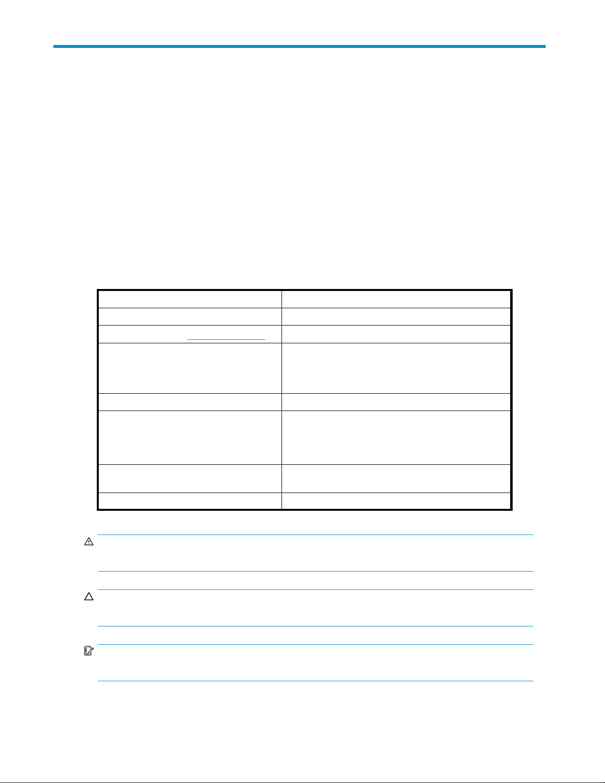
Front panel components
Item
1
2
Description
Hard drive b
FrontunitID(UID)module
Front panel LEDs
1
ays
2
15486
Item
1
2
3
iption
Descr
Heartbeat LED
Fault LED Amber = Fault condition
tton/LED
UID bu
s
Statu
Green = System activity
Off=Nosystemactivity
Off=Nofaultcondition
Identified
Blue =
ashing = Active remote management
Blue fl
Off = No active remote management
15460
user guide
11
Page 12
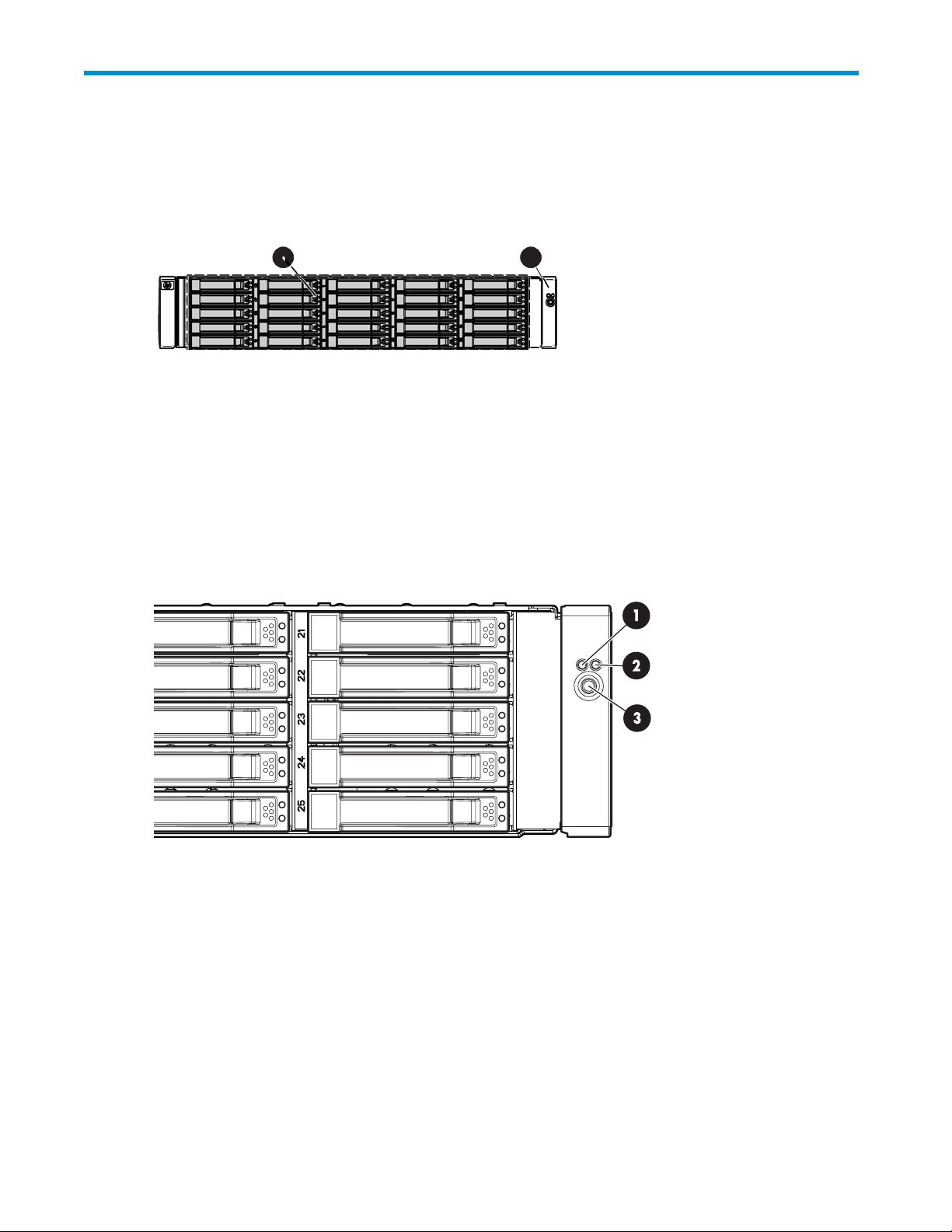
Rear panel comp
onents
15461
Item
1
2
3
4
5
6
7Futureuse
8
9
Description
Power supply 1
Fan module 1
7-segment display board
SAS in connector
SAS out connector
I/O module
Fan module 2
Power supp
ly 2
12
Identifying the components
Page 13
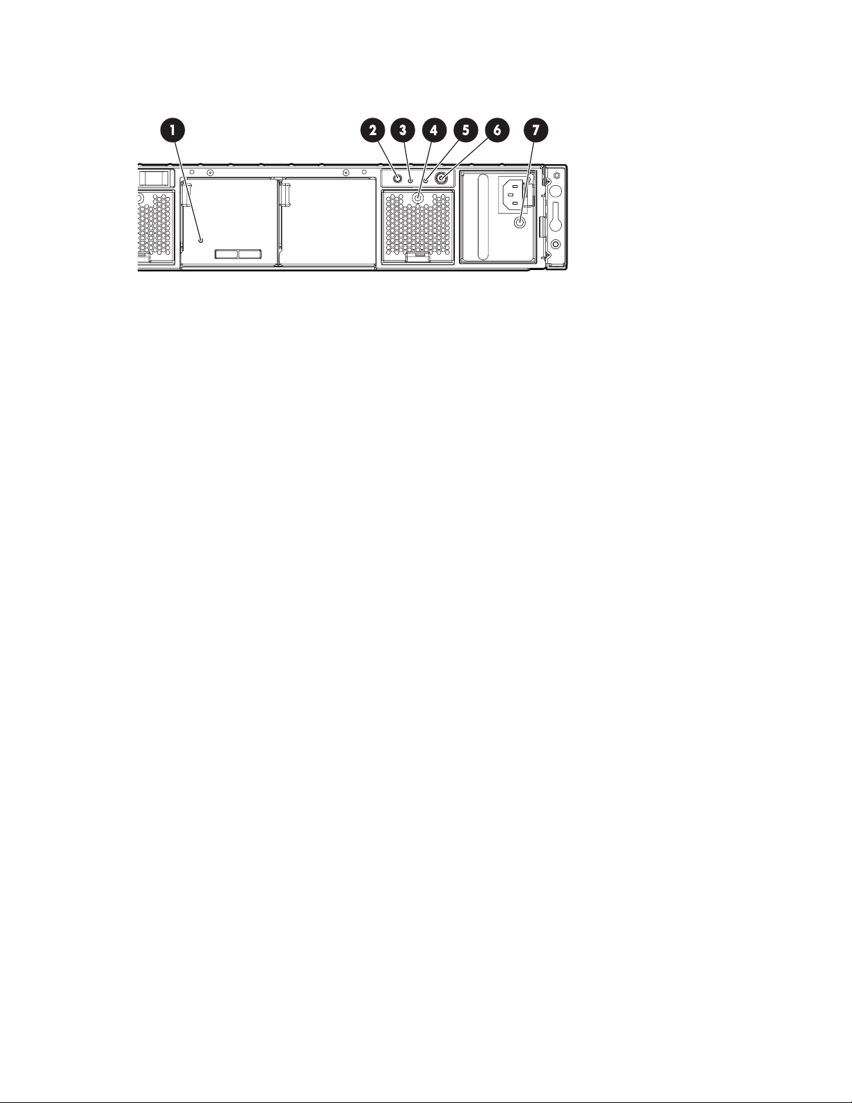
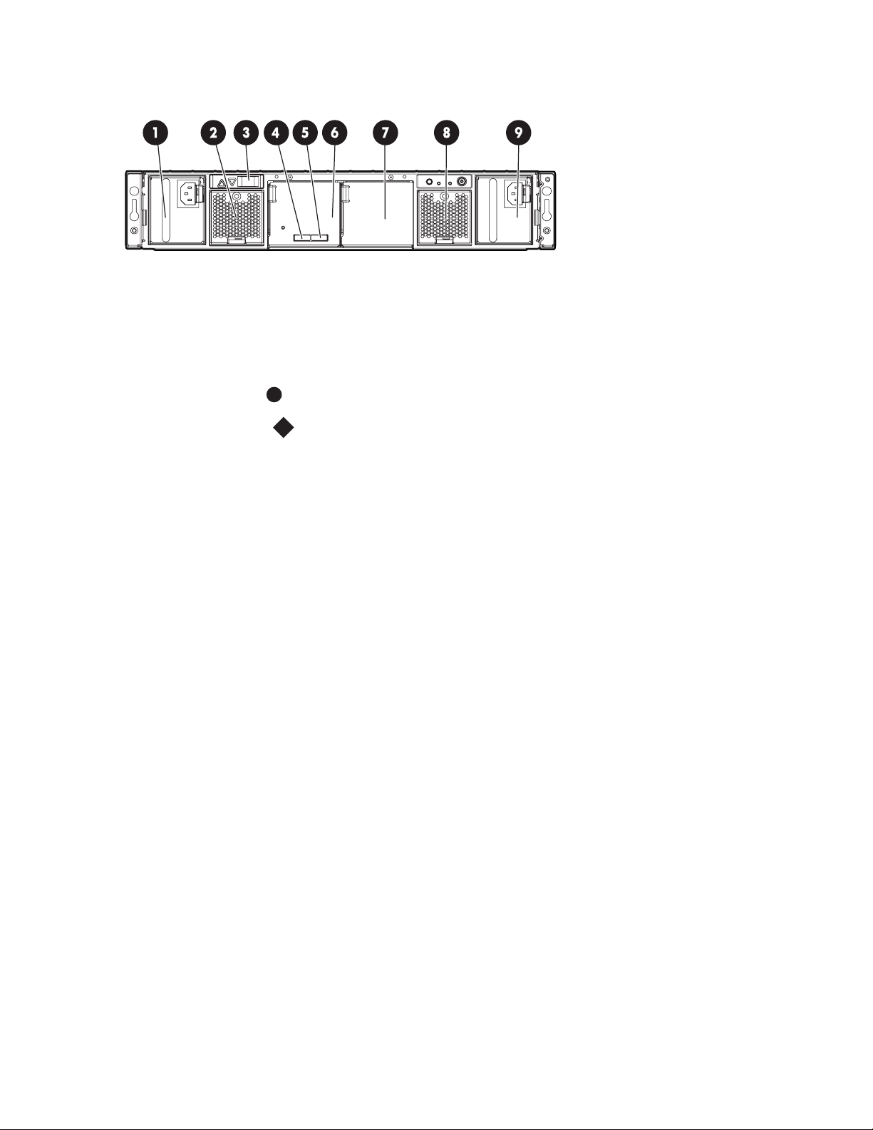
Rear panel LEDs
and buttons
15462
Item
1
2
3
4
5
6
7
Description Status
I/O module LED
UID button/LED Blue = Identified
Heartbeat LED
Fan module LED Green = Normal operation
System faul
Power On/Standby
button/system power
LED
Power supply LED
tLED
Green = System activity
Amber = Fault
Off=Nosystemactivity
Blue flashing = Active remote ma nagement
Off=Noacti
Green = System activity
Amber = Fault
Off=Nosystemactivity
Amber = Fault condition
Off=Fanunseatedformconnectororfailed
Amber = Fault condition
Off=Nofaultcondition
Green = On
Amber = Standby (power present)
Off=Off
Green = Power turned on and power supply functioning properly
Amber = Standby (auxiliary power present)
Blinking amber = Power to this power supply not present
Off = One or more of the following conditions exists:
• A/C power unavailable
• Power supply failed
• Power supply exceeded current limit
ve remote management
user guide
13
Page 14
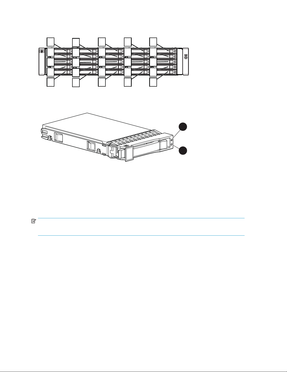
Hard drive bay n
umbers
1
2
3
4
5
Hard drive LEDs
Item
1
2
Description
Fault/UID LED (amber/blue)
Online/activity LED (green)
6
7
8
9
10
11
12
13
14
15
16
17
18
19
20
21
22
23
24
25
15463
1
2
15464
Hard dri
NOTE:
Predictive failure alerts can occur only when the enclosure is connected to a Smart Array controller.
ve LED combinations
14
Identifying the components
Page 15

Table 2 LED Failure/Fault Alerts
Online/activity LED (green) Fault/UID LED (amber/blue)
On,off,orflashing
On,off,orflashing
On
On
Flashing regularly (1 Hz)
Flashing regularly (1 Hz)
Alternating amber and blue
Steadily blue The drive is operating normally,
er, flashing regularly (1 Hz)
Amb
Off
Amber, flashing regularly (1 Hz)
Off
Interpretation
The drive has failed, or a predictive
failure alert has been received for
this drive; it also has been selected
by a management application.
and it has been selected by a
management application.
edictive failure alert has been
Apr
ceived for this drive. Replace the
re
ive as soon as possible.
dr
The drive is online, but it is not
currently active.
Do not remove the drive. Removing
a drive may terminate the current
operation and cause data loss.
The drive is part of an array that
is undergoing capacity expansion
orastripesizemigration,buta
predictive failure alert has been
received for this drive. To minimize
the risk of data loss, do not replace
the drive until th e expansion or
migration is complete.
Do not remove the drive.
Removing a drive may terminate
the current operation and cause
data loss. The drive is rebuilding,
or it is part of an array that is
undergoing capacity expansion or
astripesizemigration.
Flashing irregularly
Flashing irregularly
Off
Off Amber, flashing regularly ( 1 Hz) A predictive failure alert has been
Off Off The drive is offline, a spare, or not
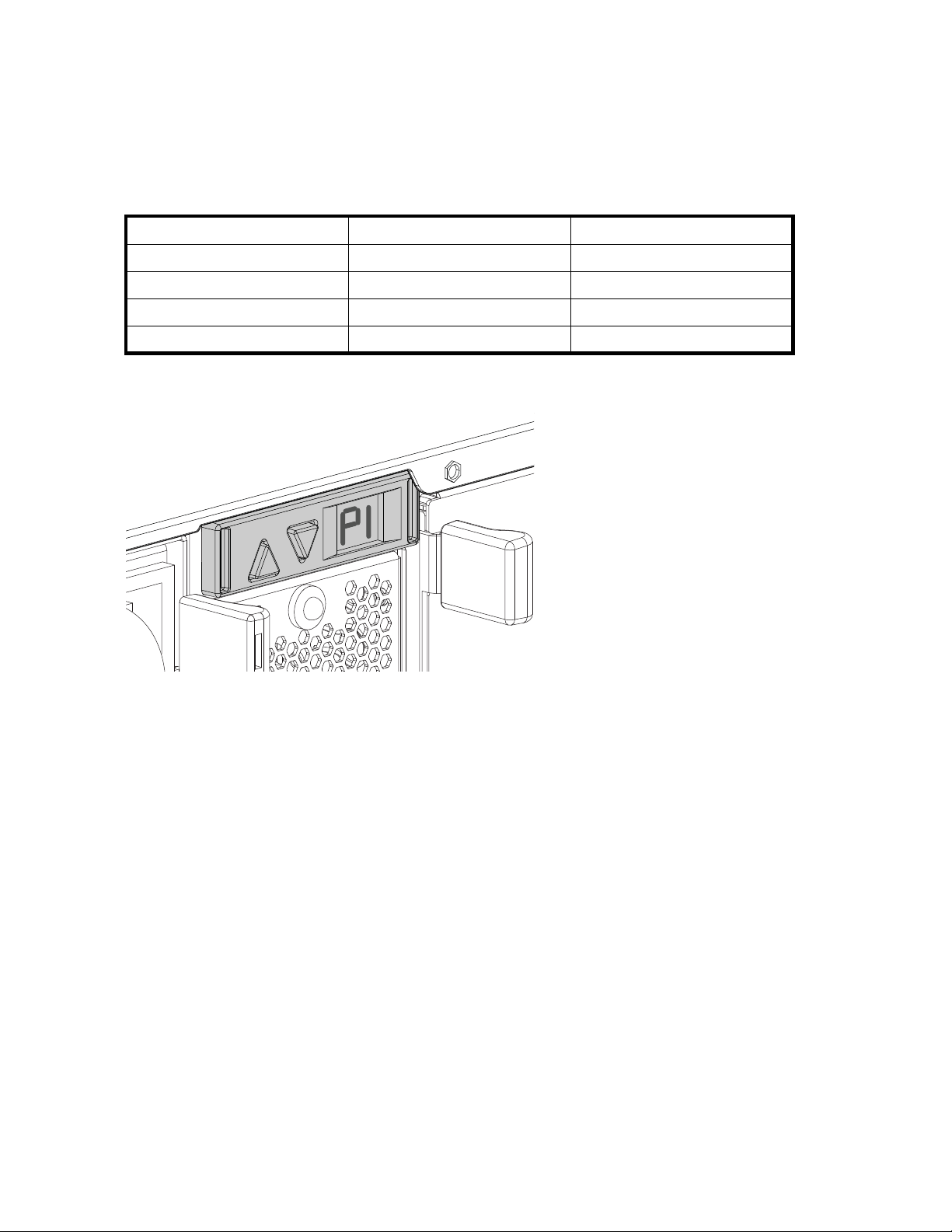
7-segment display board
The 7-segment display board allows you to identify the following:
• The port on the host controller to which the MSA70 is connected. There are two external ports on
the host controller; each port allows you to connect up to two MSA70s to the controller. Because
Amber, flashing regularly (1 Hz)
Off
Steadily amber
The drive is active, but a predictive
failure alert has been received for
this drive. Replace the drive as
soon as possible.
The drive is active, and it is
operating normally.
A critical fault condition has been
identified for this d rive, and the
controller has placed it offl ine.
Replace the drive as soon as
possible.
received for this drive. Replace the
drive as soon as possible.
configured as part of an array.
user guide
15
Page 16
one additional MSA70 can be attached to each of the MSA70s, a total of four MSA70s can be
connected to the host controller. See Cascading (1+1) configuration.
• The box ID number assigned to the MSA70 based on how it is connected to the host controller.
If there are multiple MSA70s attached to the controller, the box ID num ber identifies the order
in which they are attached.
When the MSA70 is connected to the host controller, the controller automatically assigns the port and
box ID numbers to the enclosure. The following table shows MSA70 enclosures and their associated
port and box ID assignments:
Storage Enclosure
MSA70 enclosure 1
MSA70 enclosure 2
MSA70 enclo
MSA70 enclosure 4
sure 3
Port Box ID
P1 B1
P1
P2 B3
P2
B2
B4
To view the port to which the MSA70 is connected, press the up arrow button on the 7-segment display
board. To view the box ID number, press the down button.
15487
You can also view the port and box ID numbers within Array Configuration Utility (ACU), HP Systems
Insight Manager (HP SIM), and Array Diagnostic Utility (ADU).
16
Identifying the components
Page 17

2 Powering up and powering down
the enclosure
IMPORTANT:
Before installing this product, read the
Powering up
Observe the following guidelines before p owering up the enclosure:
• Install all components of the enclosure.
• Install hard drives in the enclosure so the connected host controller can identify and configure
them at powerup.
• Always power up the enclosure first, and then the server. This ensures that the servers, during
their d iscovery, see the enclosure as an operational device. If you do not power up the enclosure
before powering up the servers, you will need to power down the servers, ensure that the
enclosure is powered up, and then power back up the servers.
To power up the enclosure:
1. Complete server hardware installation and cabling. See the server documentation.
2. Connect the SAS cables and power cords to the enclosure. See Choosing a configuration.
Important Safety Information
document provided.
3. Press and hold the Power On/Standby button. Wait and observe the system power LED and fan
modules. When the enclosure powers up, the system power LED illuminates solid green and the
fans spin to a high speed, and then spin down to a low speed.
4. Power up the servers. See the server documentation.
Powering down
CAUTION:
Be sure that the server is the first unit to be powered down and the last to be powered back up. Taking
this precaution ensures that the system does not erroneously mark the drives as failed when the server is
powered up.
IMPORTANT:
If installing a hot-plug device, it is not necessary to power down the enclosure.
To power down the enclosure:
1. Power down any attached servers. See the server documentation.
2. Press the Power On/Standby button on the enclosure. Wait for the system power LED to change
from green to amber.
3. Disconnect the power cords.
The system is now without power.
user guide
17
Page 18

18
Powering up and powering down the enclosure
Page 19

3 Setting up t he enclosure
Environmental requirements
When installing the enclosure in a rack, select a location that meets the environmental standards
described in this section.
Space and airflow requirements
To allow for s
when deciding where to install a rack:
• Leave minimum clearance of 63.5 cm (25 in) in front of the rack.
• Leave minim
• Leave minimum clearance of 121.9 cm (48 in) from the back of the rack to the back of another
rack or row of racks.
HP enclosur
Therefore,
enter the cabinet, and the rear door must be adequately ventilated to allow the warm air to escape
from the cabinet.
CAUTION:
To prevent
CAUTION:
When a vertical space in the rack is not filled by a server or rack component, the gaps bet ween the
components cause changes in airflow through the rack and across the servers. Always use blanking
panels to fill empty vertical spaces in the rack. This arrangement ensures proper airflow. Using a rack
without blanking panels results in improper cooling that can lead to thermal damage.
The 9000 and 10000 Series racks provide proper server cooling from flow-through perforations in the
front and rear doors that provide 64 percent open area for ventilation.
ervicing and adequate air flow, observe the following space and airflow requirements
um clearance of 76.2 cm (30 in) behind the rack.
es draw in cool air through the front door and expel warm air through the rear d oor.
the front and rear rack doors must be adequately ventilated to allow ambient room air to
improper cooling and damage to the equipm ent, do not block the ventilation openings.
CAUTION:
When using a Compaq-branded 7000 Series rack, you must install the high airflow rack door insert
[P/N 327281-B21 (42U) or P/N 157847-B21 (22U)] to provide proper front-to-back airflow and cooling.
CAUTION:
If a third-party rack is used, observe the following additional requirements to ensure ade quate airflow
and to prevent damage to the equipment:
• Front and rear doors—If the 42U rack includes closing front and rear doors, you must allow 5,350 sq
cm (830 sq in) of h oles evenly distributed from top to bottom to permit adequate air flow (equivalent
to the required 64 percent open area for ventilation).
• Side—Theclearancebetweentheinstalledrackcomponentandthesidepanelsoftherackmustbea
minimum of 7 cm (2.75 in).
user guide
19
Page 20

Rack planning r
The rack resource kit ships with all HP-branded or Compaq-branded 9000, 10000, and H9 Series racks.
For more information on the content of each resource, see the rack resource kit documentation.
If you intend to
deployment at
esources
deploy and configure multiple servers in a single rack, see the white paper on high-density
the HP website: h
Temperature requirements
To ensure continued safe and reliable equipment operation, install or position the enclosure in a
well-ventilated, climate-controlled environment.
The maximum recommended ambient operating temperature (TMRA) for most enclosure products is 35°C
(95°F). The temperature in the room where the rack is located must not exceed 35°C (95°F).
CAUTION:
To reduce the risk of damage to the equipment when installing third-party options:
• Donotpermitoptionalequipmenttoimpedeairflow around the enclosure or to increase the internal
rack temperature beyond the maximum allowable limits.
• Do not exceed the manufacturer’s TMRA.
Power requirements
Installation of this equipment must comply with local and regional electrical regulations governing the
installation of IT equipment by licensed electricians. This equipment is designed to operate in installations
covered by NFPA 70, 1999 Edition (National Electric Code) and NFPA-75, 1992 (code for Protection
of Electronic Computer/Data Processing Equipment). For electrical p ower ratings on options, see the
product rating label or the user documentation supplied with that option.
ttp://www.hp.com/products/servers/platforms.
WARNING!
To reduce the risk of personal injury, fire, or damage to the equipment, do not overload the AC supply
branch circuit that provides power to the rack. Consult the electrical authority having jurisdiction over
wiring and installation requirements of your facility.
CAUTION:
Protect the enclosure from power fluctuations and temporary interruptions with a regulating UPS. This
device protects the hardware from damage caused by power surges and voltage spikes and keeps the
enclosure in operation during a power failure.
When installing more than one enclosure, you may need to use additional power distribution devices to
safely provide power to all devices. Observe the following guidelines:
• Balance the enclosure power load between available AC supply branch circuits.
• Do not allow the overall system AC current load to exceed 80 percent of the branch circuit
AC current rating.
• Do not use comm on power outlet strips for this equipment.
• Provide a separate electrical circuit for each power supply in the enclosure.
20
Setting up the enclosure
Page 21

Electrical grounding requirements
The enclosure must be grounded properly for proper operation and safety. In the United States, you must
install the equ
well as any local and regional building codes. In Canada, you must install the equipment in accordance
with Canadian Standards Association, CSA C22.1, Canadian Electrical Code. In all other countries,
you must instal
as the International Electrotechnical Commission (IEC) Code 364, parts 1 through 7. Furthermore, you
must be sure that all power distribution devices used in the installation, such as b ranch wiring and
receptacles, are listed or certified grounding-type devices.
Because of the high ground-leakage currents associated with multiple enclosures conne cted to the same
power source, HP recommends the use of a power distribution unit (PDU) that is either permanently wired
to the buildi
NEMA locking
Using commo
ipment in accordance with NFPA 70, 1999 Edition (National Electric Code), Article 250, as
ltheequipmentinaccordancewithanyregionalornationalelectricalwiringcodes,such
ng’s branch circuit or includes a nondetachable cord that is wired to an industrial-style plug.
-style plugs or those complying with IEC 60309 are considered suitable for this purpose.
n power outlet strips for the enclosure is not recommended.
Rack warnings
WARNIN G!
To reduce the risk of personal injury or damage to the equipment, be sure that:
• The leveling jacks are extended to the floor.
• The full weight of the rack rests on the leveling jacks.
• The stabilizing feet are attached to the rack if it is a single-rack installation.
• The racks are coupled together in multiple-rack installations.
• Only one component is extended at a time. A rack may become unstable if more than one
component is extended for any reason.
WARNIN G!
To reduce the risk of personal i njury or equipment damage when unloading a rack:
• At least two people are needed to safely unload the rack from the pallet. An empty 42U rack can
weighasmuchas115kg(253lb),canstandmorethan2.1m(7ft)tall,andmaybecomeunstable
when being moved on its casters.
• Never stand in front of the rack when it is rolling down the ramp from the pallet. Always handle the
rack from both sides.
Shipping contents
When unpacking the MSA70 enclosure, locate the following items:
• MSA70 enclosure
• Rack mounting hardware kit
• Power cords (2 )
• SAS cable
• Documentation kit
user guide
21
Page 22

Rack mounting hardware kit contents
The rack mounting hardware kit provides the required components for quick deployment in
Compaq-branded, HP-branded, and most square- and round-hole third-party racks. The adjustable
feature of the r
If you are installing the MSA70 enclosure in an M-Series rack, contact an authorized reseller to obtain an
M-Series Rack Rail option kit.
ack rails enables installation in racks with depths of 69.90 to 76.2 cm (27.52 to 30.00 in).
1
3
2
15601
Item
1
2
3
Description
Rack rail (left)
Rack rail (right)
Pins for round-hole rack conversion (8)
In addition to these supplied items, you may need a No. 2 Phillips screwdriver.
Converting rails for round-hole racks
The rack rails ship configured for square-hole racks. To convert the rack rails for use in a round-hole rack:
1. Locate the bag of miscellaneous hardware that ships with the rack rails.
2. Locate th
3. Use a No.
of the rail.
e eight round-hole pins.
2 Phillips screwdriver to remove the standard pins from the front and back ends
4. Install four round-hole pins into the rail.
22
Setting up the enclosure
15489
Page 23

5. Repeat steps 3 and 4 for the second rail.
Installing the enclosure into the rack
15600
To install t
he enclosure into a rack:
1. Secure the front end of the rails to the rack.
IMPORTANT:
Do not remove the pins from the ends of the rack rails unless you are c onverting the rails for use
in round-hole racks. These load-bearing pins are designed to fit through the holes without being
removed.
IMPORTANT:
Be sure that the scissor-type locking latches engage the rack fully when the pins extend through
the holes marked with the template.
NOTE:
Identify the left (L) and right (R) rack rails by markings stamped into the sheet metal.
2. Secure the back end of the rails to the rack.
15485
user guide
23
Page 24

IMPORTANT:
Be sure that the scissor-type locking latches engage the rack fully when the pins extend through
the holes marked with the template.
15488
3. Slide the chassis into the rack.
4. Use the thumbscrews on the front of the chassis to secure it to the rack.
5. Usetheshippingbrackettosecuretheenclosureforshipping:
IMPORTANT:
Use of the shipping bracket is required only when the rack is shipped with the MSA70 enclosure
installed.
a. Loosen the thumbscrew on the shipping bracket.
b. Slide the shipping bracket forward until it engages the chassis.
c. Tighten the thumbscrew .
If you are installing the enclosure into a telco rack, order the appropriate option kit at the RackSolutions
website: h
install t
ttp://www.racksolutions.com/hp. Follow the enclosure-specific instructions on the website to
he rack brackets.
Installing hardware options
Install any hardware options before initializing the enclosure. For options installation information, see the
option documentation. For enclosure-specific information, see Installing hardware drives.
Installing ser vers
l the servers in the rack directly above the enclosure. See the server documentation.
Instal
NOTE:
When installing servers and enclosures, HP recommends installing all enclosures at the bottom of the
rack. To optimize cabling access, avoid interleaving the enclosure and server products.
Choosing a configuration
Cable procedures vary, depending on the confi guration. Choose one of the following configurations.
24
Setting up the enclosure
Page 25

NOTE:
OUT
TheleftconnectoroftheI/Omoduleisforinputfromtheserver.TherightconnectoroftheI/Omoduleis
for output to another enclosure. See the icons on the cables and enclosure to assist in proper connection.
Single-enclosure configuration
S
A
S
OUT
1
3
Item
1
2
3
Description
Server
SAS cable
MSA70 enclosure
Cascading (1+1) configuration
5
IN
2
15465
1
S
A
S
IN
2
3
4
15466
user guide
25
Page 26

Item
1
2
3
4
5
Description
Server
SAS cable
SAS cable
MSA70 enclosure 1
MSA70 enclosure 2
Cabling the enclosure
After installing the enclosure in a rack, connect the SAS cables and power cords to the rear panel.
SAS cabling g
Observe the f
• Only use supported SAS cables with 3-GB connectors.
• Ensure that the servers at tached to the enclosure are powered down and power cords are
uidelines
disconnecte
Supported cables
A 0.5-m (1.64-ft) SAS cable ships standard with the enclosure. HP recommends using the shortest cable
possible, however, other supported cable lengths between SAS ports are 2 m (6.56 ft), 4 m (13.12 ft), and
6 m (19.69 ft). To acquire different lengths, contact the nearest authorized HP reseller.
Power cords
The power c
product and for the voltage and current marked on the electrical ratings label of the product. The voltage
and current rating for the cord should be greater than the voltage and current rating marked on the
product. In addition, the diameter of the wire must be a minimum of 1.00 mm
maximum length may be up to 3.66 m (12 ft).
WARNING
To reduc
• Do not disable the power cord grounding plug. The grounding plug is an important safety feature.
• Plug the power cord into a grounded (earthed) electrical outlet that is easily accessible at all times.
• Unplug t
• Do not route the power cord where it can be walked on or pinched by items placed against it. Pay
particular attention to the plug, electrical outlet, and the point where the cord extends from the
storage system.
!
e the risk of electric shock or damage to the equipment:
he power cord from the power supply to disconnect power to the equipment.
ollowing guidelines:
d before connecting SAS cables.
ord should be approved for use in your country. The power cord must be rated for the
2
or 18 AWG, your
To connect AC power cords:
1. Connect the power cords to the power supplies.
2. Connect the power cords to the AC power source.
26
Setting up the enclosure
Page 27

Updating firmware
After installing hardware and powering up the enclosure for the first time, be sure to verify that the host
controller, the enclosure, and hard drives have the latest firmware. You can identify which firmware
versions you ha
and ACU. ADU al
not the MSA70.
NOTE:
The firmware for both the SAS and SATA hard drives is upgradeable.
For firmware and software updates, see the HP website: http://h18004.www1.hp.com/support/files/
storage/us/index.html. You can also update the firmware on the server, controller, enclosure, and hard
drives using Smart Components. See Smart Components for ROM Flash.
You can receive proactive support alerts, such as Customer Advisories, as well as updates on drivers,
software, firmware, and customer replaceable components, via e-mail through HP Subscriber’s Choice.
Sign up for Subscriber’s Choice at the following HP website: h
select the appropriate product.
ve for the host controller, the MSA70, and the installed hard drives through HP SIM
lows you to view the firmware versions for the host controller and hard driv es, but
ttp://www.hp.com/go/myadvisory and
user guide
27
Page 28

28
Setting up the enclosure
Page 29
4 Installing hard drives
Hard drive options
The enclosure supports up to 25 SAS or SATA hard drives. Always populate hard drive bays starting with
thelowestdevicenumber(seeHard drive bay numbers).
Hard drive guidelines
When adding hard drives to the enclosure, observe the following general guidelines:
• The system automatically sets all device numbers.
• If only one h
• Drives must be the same capacity to provide the greatest storage space efficiency when drives are
grouped together into the same drive array.
NOTE:
ACU does not
Installingaharddrive
ard drive is used, install it in the bay with the lowest device number.
support mixing SAS and SATA drives in the same logical volume.
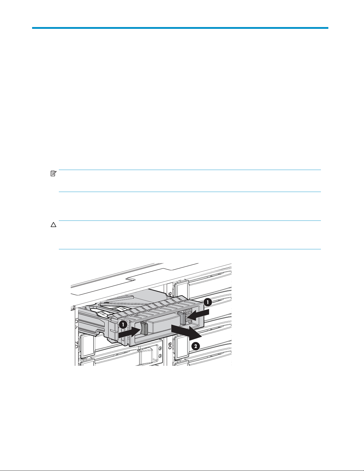
CAUTION:
To prevent improper cooling and thermal damage, do not operate the enclosure unless all bays are
populated with either a component or a blank.
1. Remove the
hard drive b lank.
15467
2. Press the latch and slide it to the right to disengage the lever (1), and then open the lever (2). Make
sure that the lever is in the fully opened position before inserting the drive into the bay.
user guide
29
Page 30
1
2
15468
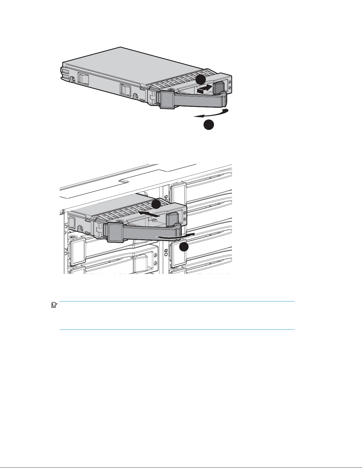
3. Slide the hard drive into the bay (1), pressing firmly on the drive to seat it. Close the lever (2), making
sure that it is flush with the front of the drive.
1
2
15469
IMPORTANT:
Whenthedriveisinserted,thedriveLEDsflash for 2 seconds to indicate that the drive is
dproperlyandreceivingpower.
seate
4. Determine the status of the hard drive (see Hard drive LED combinations).
30
Installing hard drives
Page 31

5Configuring the enclosure
Configuration tools
Array Configur
NOTE:
ACU does not support mixing SAS and SATA drives in the same logical volume.
ACU is a browser-based utility with the following features:
• Runs as a local application or remote service
• Supports online array capacity expansion, logical drive extension, assignment of online spares,
• Suggests the optimum configuration for an unconfigured system
• Provides different operating modes, enabling faster configu ration or greater control over the
• Remains available any time that the server is on
• Displays on-screen tips for individual steps of a configuration procedure
For optimum performance, the minimum display settings are 800 × 600 resolution and 256 colors.
Servers running Microsoft operating systems require Internet Exp lorer 5.5 (with Service Pack 1) or later.
For Linux servers, see the README.TXT file for additional browser and suppor t information.
For more information, see the ACU section of the array configuration reference guide on the
Documentation CD or the HP website: h
ation Utilit y
and RAID or stripe size migration
configuration options
ttp://www.hp.com.
Option ROM Configuration for Arrays
Before installing an operating system, you can use the ORCA utility to create the first logical drive, assign
RAID levels, and establish online spare configurations.
The utility also provides support for the following functions:
• Reconfiguring one or more logical drives
• Viewing the current logical drive configuration
• Deleting a logical drive configuration
• Setting the controller to be the boot controller
If you do not use the utility, ORCA defaults to the standard configuration.
For more information regarding array controller configuration, see the controller user guide.
For more information regarding the default configurations that ORCA uses, see the HP ROM-Based
Setup Utility user guide on the Documentation CD.
Smart Components for ROM Flash
To update the firmware on the server, controller, hard drives, or enclosure, use Smart Components. These
components are available on the Firmware Maintenance CD. A more recent version of a particular
component might be available on the support page of the HP website: h
Components for controller and hard drive firmware updates are also available from the software and
drivers page for storage products (h
ttp://www.hp.com/support.
ttp://www.hp.com/support/proliantstorage).
user guide
31
Page 32

1. Find the most recent version of the component that you require. Components for controller firmware
updates are available in offline and online formats.
2. Follow the instructions for installing the component on the server. These instructions are given with
the CD and are provided on the same Web page as the component.
3. Follow the additional instructions that describe how to use the component to flash the ROM. These
instructions are p rovided with each component.
Management tools
HP Systems Insight Manager
HP SIM is a web-based application that allows system administrators to accomplish normal administrative
tasks from any remote location, using a web browser. HP SIM provides device management capabilities
that consolidate a nd integrate management data from HP and third-party devices.
IMPORTANT:
You must install and use HP SIM to benefit from the Pre-Failure Warranty for processors, SAS and
SCSI hard drives, and memory modules.
For additional information, see the Management CD in the HP ProLiant Essentials Foundation Pack or the
HP SIM website: h
ttp://www.hp.com/go/hpsim.
Management Agents
Management Agents provide the information to enable fault, performance, and configuration
management. The agents allow e asy manageability of the server through HP SIM software, and third-party
SNMP management platforms. Management Agents are installed with every SmartStart-assisted
installation or can b e installed through the HP PSP. The Systems Management homepage provides status
and direct access to in-depth subsystem information by accessing data reported through the Management
Agents. For additional information, see the Management CD in the HP ProLiant Essentials Foundation
Pack or the HP website: h
ttp://www.hp.com/servers/manage.
Diagnostic tools
Integrated Management Log
The Integrated Management Log (IML) records events and stores them in an easy-to-view form. The IML
timestamps each event with 1-minute granularity.
You can view recorded events in the IML in several ways, including the following:
• From within HP SIM (see HP Systems Insight Manager)
• From within Survey Utility
• From within operating system-specificIMLviewers
• For NetWare: IML Viewer
•ForWindows:IMLViewer
• For Linux: IML Viewer Application
• From within the iLO user interface
• From within HP Insight Diagnostics
For more information, see the Ma nagem ent C D in the HP ProLiant Essentials Foundation Pack.
32
Configuring the enclosure
Page 33

Array Diagnosti
cUtility
ADU is a web—bas
report provide
ADU can be acce
ed application that creates a report of all HP storage controllers and hard drives. This
s vital information to assist in identifying faults or conditions that may require attention.
ssed from the SmartStart CD or downloaded from the HP website: h
Remote support and analysis tools
Open Services Event Manager
OSEM is a standalone tool that performs real-time reactive and proactive service event filtering, analysis,
and notification. The tool gathers event data from SNMP traps or information provided over an HTTP
interface and notifies an administrator or HP through SMTP and ISEE.
For more information, see the HP website: h
ttp://h18000.www1.hp.com/support/svctools/.
Keeping the system current
Change control and proactive notification
HP offers Change Control and Proactive Notification to notify customers 30 to 60 days in advance of
upcoming hardware and software changes on HP commercial products.
For more information, see the HP website: h
Natural language search assistant
ttp://h18023.www1.h p.com/solutions/pcsolutions/pcn.html.
ttp://www.hp.com.
The natural language search assistant, located at http://www.hp.com/support/natural_language_search,
is a search engine that finds information on HP products, including ProLiant servers. The search engine
responds to queries entered in question form.
Care Pack
HP Care Pack Services offer upgraded service levels to extend and expand standard product warranty
with easy-to-buy, easy-to-use support packages that help you make the most of your server investments.
See the Care Pack website: h
ttp://www.hp.com/hps/carepack/servers/cp_proliant.html.
user guide
33
Page 34

34
Configuring the enclosure
Page 35

6 Troubleshooting
When the enclosure does not start
If the enclosure does not power up:
1. Verify that the server, monitor, and enclosure are plugged in.
2. Verify that the server and monitor are working.
3. Verify that the power source is working:
a. Ensure that the Power On/Standby button was pressed firmly and held for approximately
three seconds.
b. View the system power LED on the back panel (see Rear panel LEDs and buttons).
4. Verify that the power supplies are working properly by viewing the power supply LEDs on the
back panel (see Rear panel LEDs and buttons).
5. Disconnect the AC power cords from both enclosure power supplies and reconnect them.
6. Restart the enclosure.
IMPORTANT:
If the system does not restart, proceed to Diagnostic steps.
7. Check the enclosure for the following normal power-up sequence to be sure that the system meets
the minimal hardware requirements a n d i s powered up during normal operations:
a. The front panel power LED turns from standby/off (am b er) to on (solid green).
b. Thefansspinuptoahighspeed,andthenspindowntoanormaloperatingspeed.
Diagnostic steps
Are the power supply/ fan module LEDs green?
Answer
No
Yes
Possible Reasons Possible Solutions
• The power cords are not
connected or AC power is not
available.
• The power supp ly may not be
inserted properly, it may have
a damaged connector, or it
may have failed.
• The system midplane may need
to be replaced.
System is functioning properly.
• Be sure that the power cord is
connected to the power supply.
• Be sure that the p ower supply
is undamaged and is fully
seated.
• Be sure that all pins on
connectors and components
are straight.
• Contact an authorized service
provider for assistance.
If the system power LED is off, do
the following:
1. Press the Power On/Standby
buttonandholdfor
approximately three seconds.
2. See Is the system power LED
green?
No action required
user guide
35
Page 36

Is the system po
wer LED green?
Answer
No
Possible Reasons Possible Solutions
• The Power On/Standby button
has not been pressed firmly or
held long enough.
• The power supply may not be
inserted properly, it may have
a damaged connector, or it
may have failed.
• The system may have
experienced a short. Controller
firmware may be corrupted.
• The system midplane and/or
power button/LED assembly
may need to be replaced.
Recognizing hard drive failure
In an HP enclosure, a steadily glowing fault LED indicates that a drive has failed.
Other indications of failed hard drives a re as follows:
• ACU represents failed drives with a distinctive icon.
• HP SIM can detect failed drives remotely across a network. (For more information about HP SIM,
see the documentation on the Management CD.)
• ADU lists all failed drives.
• CPQONLIN identifies failed drives in a NetWare environment.
For additional information about diagnosing hard drive problems, see the HP ProLiant Servers
Troubleshooting G uide.
• Firmly press the Power
On/Standby button and
hold for approximately three
seconds.
• Be sure that the power supply
is undamaged and is fully
seated. Besurethatallpinson
connectors and components
are straight.
• Be sure that all components
are fully seated.
• Flash the controller firmware
(see Smart Components for
ROM Flash).
• Contact an authorized service
provider for assistance.
CAUTION:
Sometimes, a drive that has previously failed may seem to be operational after the system is power-cycled
or, for a hot-pluggable drive, after the drive has been removed and reinserted. However, continued use of
such marginal drives may eventually result in data loss. Replace the marginal drive as soon as possible.
Effects of a hard drive failure
When a hard drive fails, all logical drives that are in the same array are affected. Each logical drive in an
array may be using a different fault-tolerance method, so each logical drive can be affected differently.
• RAID 0 configurations cannot tolerate drive failure. If any physical drive in the array fails, all
non-fault-tolerant (RAID 0) logical drives in the same array also fail.
• RAID 1+0 configurations can tolerate multiple drive failures as long as no failed drives are
mirrored to one another (with no spares assigned).
• RAID 5 configurations can tolerate one drive failure (with no spares assigned).
• RAID 6 with ADG configurations can tolerate simultaneous failure of two drives (with no spares
assigned).
36
Troubleshooting
Page 37

Compromised fau
If more hard drives fail than the fault-tolerance method allows, fault tolerance is compromised, and the
logical drive f
errors. You are likely to lose data, although it can sometimes be recovered.
One example of a situation in which compromised fault tolerance m ay occur is when a drive in an array
fails while another drive in the array is b eing rebuilt. If the array has no online spare, any logical drives
in this array that are configured with RAID 5 fault tolerance will fail.
Compromised fault tolerance can also be caused by non-drive problems, such as a faulty cable or
temporary pow
drives. Howe
problem occurred.
lt tolerance
ails. In this case, all requests from the operating system are rejected with unrecoverable
er loss to a storage system. In such cases, you do not need to replace the physical
ver, you may still have lost data, especially if the system was busy at the time that the
Recovering from compromised fault tolerance
If fault tolerance is compromised, inserting replacement drives does not improve the condition of the
logical volume. Perform the following procedure to recover data:
1. Power down the enclosure (see Powering down).
2. Check for loose, dirty, broken, or bent cabling and c onnectors on all devices.
3. Power up the enclosure (see Powering up).
NOTE:
In some cases, a marginal drive is operational long enough to allow backups of important
files.
4. Make copies of important data, if possible.
5. Replace any failed drives. Read Factors to consider before replacing hard drives before replacing
thefailedharddrives.
Factors to consider before replacing hard drives
Insystemsthatuseexternaldatastorage,besurethattheserveristhefirstunittobepowereddownand
the last to be powered back up. Taking this precaution ensures that the system does not erroneously mark
the drives as failed when the server is powered up.
Before replacing a degraded drive:
• Open HP SIM and inspect the Error Counter window for each physical drive in the same array
to confirm that no other drives have any errors. For details, see the HP SIM documentation
on the Management CD.
• Be sure that the array has a current, valid backup.
• Use replacement drives that have a capacity at least as great as that of the smallest drive in the
array. The controller immediately fails drives that have insufficient capacity.
To minimize the likelihood of fatal system errors, take these precautions when removing failed drives:
• Donotremoveadegradeddriveifanyotherdriveinthearrayisoffline(theonlineLEDisoff).In
this situation, no other drive in the array can be removed without data loss.
Exceptions:
• When RAID 1+0 is used, drives are mirrored in pairs. Several drives can be in a failed
condition simultaneously (and they can all be replaced simultaneously) without data loss, as
long as no two failed drives belong to the same mirrored pair.
• When RAID 6 with ADG is used, two drives can fail simultaneously (and be replaced
simultaneously) without data loss.
user guide
37
Page 38

•Iftheoffline drive is a spare, the degraded drive can be replaced.
• Donotremoveaseconddrivefromanarrayuntilthefirst failed or missing drive has been
replaced and the rebuild process is complete. (The rebuild is complete when the Online LED on
the front of the drive stops blinking.)
Exceptions:
• In RAID 6 with ADG configurations, any two drives in the array can be replaced
simultaneously.
•InRAID1+0configurations, any drives that are not mirrored to other removed or failed drives
can be simultaneously replaced offline without data loss.
Automatic data recovery (rebuild)
When you replace a hard drive in an array, the controller uses the fault-tolerance information on the
remaining drives in the array to reconstruct the missing data (the d ata that was originally on the replaced
drive) and write it to the replacement drive. This process is called automatic data recovery, or rebuild. If
fault toler
If another drive in the array fails while fault tolerance is unavailable during rebuild, a fatal system error
may occur, and all data on the array is then lost. In exceptional cases, however, failure of another drive
need not lead to a fatal system error. These exceptions include:
• Failure af
• Failure of a drive that is not mirrored to any other failed drives (in a RAID 1+0 configuration).
• Failure of a second drive in a RAID 6 with A DG configuration.
ance is compromised, this data cannot be reconstructed and is likely to be permanently lost.
ter activation of a spare drive.
Time required for a rebuild
The time required for a rebuild varies considerably, depending on several factors:
• The priority that the rebuild is given over normal I/O operations (you can change the priority
setting by using ACU)
• The amount of I/O activity during the rebuild operation
• The rotational speed of the hard drives
• The availability of drive cache
• The brand, model, and age of the drives
• Theamountofunusedcapacityonthedrives
• The number of drives in the array (for RA I D 5 and RAID 6 with ADG)
Allow approximately 15 minutes per gigabyte for the rebuild process to be completed. This figure is
conservative, and newer drive models usually require less time to rebuild.
System performance is affected during the rebuild, and the system is unprotected against further drive
failure until the rebuild has finished. Therefore, replace drives during periods of low activity when possible.
CAUTION:
If the Online LED of the replacement drive stops blinking and the amber fault LED glows, or if other drive
LEDs in the array go out, the replacement drive has failed and is producing unrecoverable disk errors.
Remove and replace the failed replacement drive.
When automatic data recovery has finished, the online LED of the replacement drive stops blinking
and begins to glow steadily.
Failure of another drive during rebuild
If a non-correctable read error occurs on another physical drive in the array during the rebuild process,
the Online LED of the replacement drive stops blinking and the rebuild abnormally terminates.
38
Troubleshooting
Page 39

If this situation occurs, restart the server. The system may temporarily become operational long enough
to allow recovery of unsaved data. In any case, locate the faulty drive, replace it, and restore data
from backup.
Drive failure in a NetWare environment
Use CPQONLIN to identify and monitor drive failure status in a NetWare environment.
Failed drives or interim recovery mode
If a drive fails and hardware fault tolerance is enabled, operation continues. Do the following:
1. Replace the drive as soon as possible.
2. Select a logical drive.
3. Press the F3 key to monitor to the status of drive recovery.
Drive status messages include:
• Interim Recovery: The logical drive is operating, but a failed drive has not been replaced.
Replace the drive as soon as possible.
• Ready for Recovery: The logical drives are queued for recovery. This status is displayed when
another logical drive is a lready rebuilding or expanding.
• Rebuilding: The array is operating and rebuilding a replacement drive or an online spare, if
one was assigned.
• Logical Drive Failed: If you have one or more logical drives that are not protected by fault
tolerance in an a rray, the data on these logical drives will be lost. ACU shows the logical
drives as FAILED. After drive replacement, any fault-tolerant logical drives rebuild. The
logical drives that were not protected (FAILED) become available for data (the devices are
reactivated automatically). If you have a backup of the data, restore the data now.
If you do not replace the failed drive, the only option, using ACU, is to delete logical drives. Do
not delete logical drives that contain valid data. Doing so results in data loss.
NOTE:
A failed status can occur on drives protected by fault tolerance if two or more physical
drives fail concurrently.
Some status messages are available without pressing the F3 key. For example, on the Main menu,
the FAILED status appears next to the logical drive that has failed. EXPANDING and REBUILDING
appear next to the array in which the activity is occurring.
Handling hard drive failures
If the c ontroller was con figured with hardware fault tolerance, complete the following steps after a
hard drive failure:
1. Determine which physical drive failed. On hot-plug drives, an amber drive failure LED illuminates.
2. If the unit containing the failed drive does not support hot-plug drives, perform a normal shutdown.
3. Remove the failed drive and replace it with a drive that is of the same capacity. For hot-plug drives,
afteryousecurethedriveinthebay,theLEDsonthedriveeachflash once in an alternating pattern
to indicate a successful connection. The online LED flashes, indicating that the c ontroller recognized
the drive replacement and began the recovery process.
4. Power up the server, if applicable.
5. The controller reconstructs the information on the new drive, based on information from the remaining
physical drives in the logical drive. While reconstructing the data on hot-plug drives, the online LED
flashes. When the drive rebuild is complete, the online LED is illuminated.
user guide
39
Page 40

NOTE:
NetWare cannot detect a single physical drive failure when using hardware-based fault tolerance.
NetWare determines that the data is still valid and accessible during the rebuilding process. However,
the driver knows that a physical drive has failed. A message is printed on the console notifying the user
that a physical drive is in a degraded state. CPQONLIN also shows that the drive has failed.
40
Troubleshooting
Page 41

A Regulator y compliance n otices
Regulatory compliance identification numbers
For the purpose of regulatory compliance certifications and identification, this product has been
assigned a unique regulatory model number. The regulatory mod el number can be found on the
product nameplate label, along with all required approval markings and information. When requesting
compliance information for this product, always see this regulatory model number. The regulatory model
number is not the marketing name or model number of the product.
Federal Com
Part 15 of the Federal Communications Commission (FCC) Rules and Regulations has established Radio
Frequency (RF) emission limits to provide an interference-free radio frequency spectrum. Many electronic
devices, including computers, generate RF energy incidental to their intended function and are, therefore,
covered by t
and B, depending upon their intended installation. Class A devices are those that may reasonably be
expected to be installed in a business or commercial environment. Class B devices are those that may
reasonabl
The FCC requires devices in both classes to bear a label indicating the interference potential of the device
as well as additional operating instructions for the user.
munications Commission notice
hese rules. These rules place computers and related peripheral devices into two classes, A
y be expected to be installed in a residential environment (for example, personal computers).
FCC rating label
The FCC rating label on the device shows the classification (A or B) of the equipment. Class B devices
have an FCC logo or ID on the label. Class A devices do not have an FCC logo or ID on the label. After
you determine the class of the device, see the c orresponding statement.
Class A equipment
uipment has been tested and found to comply with the limits for a Class A digital device, pursuant
This eq
15oftheFCCRules.Theselimitsaredesignedtoprovidereasonableprotectionagainstharmful
to Part
erence when the equipment is operated in a commercial environment. This equipment generates,
interf
and can radiate radio frequency energy and, if not installed and used in accordance with the
uses,
uctions, may cause harmful interference to radio communications. Operation of this e quipment in a
instr
residential area is likely to cause harmful interference, in which case the user will be required to correct
the interference at personal expense.
Class B equipment
This equipment has been tested and found to comply with the limits for a Class B digital device, pursuant
toPart15oftheFCCRules.Theselimitsaredesignedtoprovidereasonableprotectionagainstharmful
interference in a residential installation. This equipment generates, uses, and can radiate radio frequency
energy and, if not installed and used in accordance with the instructions, may cause harmful interference
to radio communications. However, there is no guarantee that interference will not occur in a particular
installation. If this e quipm ent does cause harmful interference to radio or television reception, which
can be determined by turning the equipment off and on, the user is encouraged to try to correct the
interference by one or more of the following measures:
• Reorient or relocate the receiving antenna.
• Increase the separation between the equipment and receiver.
• Connect the equipm ent into an outlet on a circuit that is different from that to which the receiver is
connected.
user guide
41
Page 42

• Consult the dealer or an experienced radio or television technician for help.
Declaration of
logo, United St
This device com
(1) t h i s d evi c
received, including interference that may cause undesired operation.
For questions regarding this product, contact us by mail or telephone:
• Hewlett-Pack
• 1-800-HP-INVENT (1-800-474-6836). (For continuous quality improvement, calls may be recorded
or monitored.)
For question
• Hewlett-Packard Company P. O. Box 692000, Mail Stop 510101 Houston, Texas 77269-2000
• 1 281 - 514 - 33 33
To identify t
e may not cause harmful interference, and (2) this device must accept any interference
s regarding this FCC declaration, contact us by mail or telephone:
his product, see the part, series, or model number found on the product.
Modifications
TheFCCrequirestheusertobenotified that any changes or modifications made to this device that are not
expressly approved by Hewlett-Packard Company may void the user’s authority to o perate the equipment.
Cables
Connections to this device must be made with shielded cables with metallic RFI/EMI connector hoods
in order to m
aintain compliance with FCC Rules and Regulations.
conformity for products marked with the FCC
ates only
plies with Part 15 of the FCC Rules. Operation is subject to the following t wo conditions:
ard Company P . O. Box 692000, Mail Stop 530113 Houston, Texas 77269-2000
Canadian notice (Avis Canadien)
Class A equipment
This Class A digital apparatus meets all requirements of the Canadian Interference-Causing Equipment
Regulations.
Cet appareil numérique de la classe A respecte toutes les exigences du Règlement sur le matériel
brouilleur du Canada.
Class B eq uipment
This Class B digital apparatus meets all requirements of the Canadian Interference-Causing Equipment
Regulations.
Cet appareil numérique de la classe B respecte toutes les exigences du Règlement sur le matériel
brouilleur du Canada.
European U
This product complies with the following EU Directives:
• Low Voltage Directive 7 3/23/EEC
• EMC Directive 89/336/EEC
nion regulatory notice
42
Regulatory compliance notices
Page 43

CE Compliance of this product is valid only if powered with the correct HP-provided and CE m a rked
AC adapter.
If this product has telecommunication functionality, it also complies with the essential requirements of:
• R&TTE Directive 1999/5/EC
Compliance with these directives implies conformity to harmonized European standards (European
Norms) which are listed on the EU Declaration of Conformity issued by Hewlett-Packard for this product
or product family.
The telecommunications functionality of this product may be used in the following EU and EFTA countries:
Austria,Belgium,Cyprus,CzechRepublic,Denmark,Estonia,Finland,France,Germany,Greece,
Hungary, Iceland, Ireland, Italy, Latvia, Liechtenstein, Lithuania, Luxembourg, Malta, Netherlands,
Norway,Poland,Portugal,SlovakRepublic,Slovenia,Spain,Sweden,Switzerland,andUnitedKingdom.
Notice for use in France and Italy
Italy:
Per l’uso del prodotto, è necessaria una concessione ministeriale. Si consiglia di verificare con il
distributore di fiducia o direttamente presso la Direzione Generale Pianificazione e Gestione Frequenze.
License required for use. Verify with your dealer or directly with General Direction for Frequency Planning
and Management (Direzione Generale Pianificazione e Gestione Frequenze).
France:
L’utilisation de cet equipement (2.4GHz Wireless L AN) est soumise a certaines restrictions: Cet
equipement peut etre utilise a l’interieur d’un batiment en utilisant toutes les frequences de 2400 a
2483.5MHz (Chaine 1-13). Pour une utilisation en environement exterieur, vous devez utiliser les
frequences comprises entre 2454-2483.5MHz (Chaine 10-13). Pour les dernieres restrictions, voir
http://www.art-telecom.fr.
For 2.4 GHz Wireless LAN operation of this product certain restrictions apply: This product may be
used indoor for the entire 2400-2483.5 MHz frequency band (channels 1-13). For outdoor use, only
2454-2483.5 MHz frequency band (channels 10-13) may be used. For the latest requirements, see
http://www.art-telecom.fr.
Notice for products incorporating 5GHz Wireless LAN devices
Frequency availability for 802.11a or 802.11h Wireless LAN is not currently harmonized throughout the
European Union. For compliance requirements, users should verify with their supplier, local HP office or
Telecommunications authority.
user guide
43
Page 44

Disposal of waste equipment by users in private households
in the European Union
Japanese notice
This symbol on the product or on its packaging
indicates tha
with your othe
responsibili
by handing it
for the recycling of waste electrical and electronic
equipment.
your waste equipment at the time of disposal will
help to conserve natural resources and ensure that it
is recycled in a manner that protects human health
and the environment. For more information about
where you can drop off your waste equipment for
recycling, please contact your local city office, your
household waste disposal service or the shop where
you purchased the product.
t this product must not be disposed of
r household waste. Instead, it is your
ty to dispose of your waste equipment
over to a designated collection point
The separate collection and recycling of
BSM
Inotice
Korean notice
Class A equipment
44
Regulatory compliance notices
Page 45

Class B equipment
PowercordstatementforJapan
user guide
45
Page 46

46
Regulatory compliance notices
Page 47

B Electrostatic discharge
Preventing electrostatic discharge
To prevent damaging the system, be aware of the precautions you ne ed to follow when setting up the
system or handling parts. A discharge of static electricity from a finger or other conductor may damage
system boards or other static-sensitive devices. This type of damage may reduce the life expectancy of
the device.
To prevent electrostatic damage:
• Avoid hand contact by transporting and storing products in static-safe containers.
• Keep electrostatic-sensitive parts in their containers until they arrive at static-free workstations.
• Place parts on a grounded surface before removing them from their containers.
• Avoid touching pins, lea ds, or circuitry.
• Always be properly grounded when touching a static-sensitive component or assembly.
Grounding methods to prevent electrostatic discharge
Several methods are used for grounding. Use one or more of the following methods when handling or
installing electrostatic-sensitive parts:
• Use a wrist
Wrist stra
±10 percent resistance in the ground cords. To provide proper ground, wear the strap snug against
the skin.
• Use heel s
when stan
• Use conductive field service tools.
• Use a portable field service kit with a folding static-dissipating work mat.
strap c onnected by a ground cord to a grounded workstation or computer chassis.
ps are flexible straps with a minimum of 1 megohm.
traps, toe straps, or boot straps at standing workstations. Wear the straps on both feet
ding on conductive floors or dissipating floor mats.
If you do not have any of the suggested equipment for proper grounding, have an authorized reseller
the part.
install
For more information on static electricity or assistance with product installation, contact an authorized
reseller.
user guide
47
Page 48

48
Electrostatic discharge
Page 49

CSpecifications
Environmental specifications
Specification
Temperature range
Operating
Storage
Relative humidity
Operating
Storage
Altitude
Operating
Non-operating
1
Temperature ratings shown are for sea level. An altitude rating of 1°C per 300 m (1.8°F per 1,000 ft) to 3048 m (10,000 ft)
is applicable. No direct sunlight allowed. The upper limit may be limited by the type and number of options installed.
2
Storage maximum humidity of 95% is based on a maximum temperature of 45°C (113°F). Altitude maximum for storage
corresponds to a pressure minimum of 70 KPa.
3
Maximum allowable altitude change rate is 457 m/min (1500 ft/min)
1
2
3
Value
10°C to 35°C (50°F to 95°F)
Maximumrateofchangeis10ºC/Hr(50ºF/Hr)
-30°C to 60°C (-22°F to 140°F)
Maximumrateofchangeis20ºC/Hr(68ºF/Hr)
10% to 90 % re lat ive hum i d ity (Rh )
28º C (82.4º F) maximum wet bulb temperature
non-condensing
5% to 95% relative humidity (Rh)
38.7º C (101.66º F) maximum wet bulb temperature
non-condensing
3048 m (10,000 ft)
This value may be limited by the type and number of options
installed.
9144 m (30, 000 ft)
Storage enclosure specifications
Specificati
Height
Depth
Width
Weight (maximum) 2 1.77 kg (48 lb)
Weight (no drives installed) 15.88 kg (35 lb)
on
Value
8.8 cm (3.47 in)
59 cm (23.25 in)
44.80 cm (1
7. 6 4 i n )
user guide
49
Page 50

50
Specifications
Page 51

Acronyms and Abbreviations
ACU Array Configuration Utility
ADG Advanced Data Gua rding (also known as RAID 6)
ADU Array Diagnostics Utility
CSA Canadian Standards Association
HBA host bus adapter
IEC International Electrotechnical Commission
IEEE Institute of Electrical and Electronics Engineers
IML Integrated Management Log
MSA Modular Smart Array
MSA70 HP Storage Works 70 Modular Smart Array Enclosure
NECA National Electrical Code
NEMA National Electrical Manufacturers Association
NFPA National Fire Protection Association
ORCA Option ROM Configuration for Arrays
OSEM Open Services Event Manager
PSP ProLiant Support Pack
RAID redundant array of inexpensive (or independent) disks
RBSU ROM-Based Setup U tility
SAS serial attached SCSI
SAT A serial ATA
SCSI small computer system interface
SFF small form-factor
SIM Systems Insight Manager
TMRA recommended ambient operating temperature
UID unit identification
user guide
51
Page 52

52
Acronyms and Abbreviations
Page 53

Index
A
ACU
See Array Configuration Utility
ADU
See Array Diagnostic Utility
airflow requirements,19
Array Configuration Utility,31
Array Diagnostic Utility,33
audience,7
automatic data recovery (rebuild),38,38
B
BSMI notice,44
C
cables,42
cables, supported,26
cabling guidelines,26
Canadian notice,42
Class A equipment,42
Class B equipment,42
Care Pack,33
Change Control,33
Class A equipment
Canadian n notice,42
Federal Communications Commission notice,
41
Class B equipment
Canadian notice,42
Federal Communications Commission notice,
41
component identification,11
components,11
front panel,11
rear panel,12
compromised fault tolerance,37
recovering from,37
configuration
cascading (1+),25
choosing,24
single-enclosure,25
configuration tools,31
conventions
document,7
text symbols,7
customer self repair,8
D
data recovery,38,38
Declaration of Conformity,42
diagnostic steps,35
diagnostic tools,32
document conventions,7
documentation, providing feedback,9
drive LEDs,14
E
electrical grounding requirements,21
electrostatic discharge,47
grounding methods,47
preventing,47
enclosure
cabling,26
configuring,31
installing into rack,23
environmental requirements,19
European Union regulatory notice,42
F
failureofharddriveduringrebuild,38
fault tolerance, compromised,37
FCC
See Federal Communications Commission
notice
Federal Communications Commission notice,
41
Class A e quipment,41
Class B equipment,41
FCC rating label,41
Modifications,42
firmware, updating,27
front panel
components,11
LEDs,11
G
grounding methods,47
grounding requirements,21
guidelines
cabling,26
hard drive,29
user guide
53
Page 54

H
hard drive
bay numbers,14
failure during rebuild,38
failureinaNetWareenvironment,39
failure, effects of,36
failure, handling,39
failure, recognizing,36
guidelines,29
installation,29
installing,29
LED combinations,14
LEDs,14
options,29
hard drives
installing,29
replacing,37
hardware options, installing,24
help, obtaining,8
HP ProLiant Essentials Foundation Pack,32
HP Systems Insight Manager,32
HP technical support,8
I
IML
See Integrated Management Log
installing
enclosure into rack,23
hard drives,29,29
hardware options,24
servers,24
Integrated Management Log,32
interim recovery mode,39
J
Japanese notice,44
K
kit contents,21
Korean notices,44
L
LEDs
troubleshooting,14,35
notices
BSMI,44
Canadian,42
European Union,42
FCC,41
Japanese,44
Korean,44
O
Open Services Event Manager,33
operations,17
optimum environment,19
Option ROM Configuration for Arrays,31
ORCA
See Option ROM Configuration for Arrays
P
power cord statement for Japan,45
power cords,26
power requirements,20
powering down,17
powering up,17
problem diagnosis,35
R
rack mounting hardware,21
rack planning resources,20
rack rails, converting,22
rack warnings,21
RAID configuration,31
rear panel
buttons,13
components,12
LEDs,13
rebuild
description of,38
time required for,38
regulatory compliance notices,41
remote suppor t and analysis tools,33
requirements
airflow,19
electrical g rounding,21
environmental,19
power,20
space,19
temperature,20
M
Management Agents,32
management tools,32
N
Natural language search assistant,33
54
S
servers, installing,24
shipping carton contents,21
site requirements,19
Smart Components for ROM Flash,31
space requirements,19
specifications,49
environmental,49
storage enclosure,49
Page 55

static electricity,47
Subscriber’s Choice, HP,8
support and analysis tools, remote,33
supported cables,26
symbols in text,7
Systems Insight Manager,32
T
technical support
HP,8
service locator website,8
temperature requirements,20
text symbols,7
troubleshooting,35
troubleshooting hard drives,14
W
warnings, rack,21
websites
customer self repair,8
HP,8
HP Subscriber’s Choice for Business,8
user guide
55
 Loading...