

Page 1

HP Storage Management Utility user guide
active/active firmware v2.x
Part number: 383075–002
econd edition: May 2008
S
Page 2

Legal and notice information
© Copyright 2005, 2008 Hewlett-Packard Development Company, L.P.
Confidential computer software. Valid license from HP required for possession, use or copying. Consistent with FAR 12.211 and
12.212, Commercial Computer Software, Computer Software Documentation, and Technical Data for Commercial Items are licensed
to the U.S. Government under vendor's standard commercial license.
The information contained herein is subject to change without notice. The only warranties for HP products and services are set forth
in the express warranty statements accompanying such products and services. Nothing herein should be construed as constituting
an additional warranty. HP shall not be liable for technical or editorial errors or omissions contained herein.
Microsoft, Windows, Windows XP, and Windows NT are U.S. registered trademarks of Microsoft Corporation.
Page 3

Contents
Aboutthisguide .......................... 9
Intendedaudience...................................... 9
Prerequisites ........................................ 9
Relateddocumentation.................................... 9
Documentconventionsandsymbols ............................. 10
HP installation and configurationassistance........................... 11
HPtechnicalsupport..................................... 11
Subscriptionservice ..................................... 11
HPwebsites......................................... 11
Documentationfeedback ................................... 11
1Overview ............................ 13
Featuresandrequirements ................................. 13
Pagedescription...................................... 14
Initial configurationmethods................................. 14
AccessingtheSMU .................................... 15
Changing the management port IP address through the MSA1510i controller display panel . . . . . . 16
Bestpractices....................................... 17
2View ............................. 19
Pagedescription...................................... 19
Tabs......................................... 19
Views ........................................ 20
Availabletasks ...................................... 20
Viewingstatusalerts(ViewAllStatusAlerts)........................ 21
Viewingtheeventlog(ViewEventLog) .......................... 22
Refreshingthedisplay(RefreshSystem) .......................... 22
Identifyingdevices(IdentifyDevice)............................ 23
3Configure ........................... 25
Pagedescription...................................... 25
Tabs......................................... 25
Views ........................................ 26
Availabletasks ...................................... 27
Sample configurationusedinthisdocument.......................... 30
Sample configuration—Deviceandcablingdiagram .................... 30
Sample configuration—Physical-to-logicalstoragediagram.................. 31
Sample configuration—Path/accessibilitydiagram ..................... 32
Fundamental tasks, in initial configurationsequence....................... 33
Configuringmanagementanddataports ......................... 33
Configuringthemanagementport .......................... 33
Configuringdataports............................... 35
Sample configuration status - after configuringmanagementanddataports ........ 37
Configuringharddrives................................. 38
Creatingarrays .................................. 39
Creatinglogicaldrives............................... 41
Configuration status - after configuringharddrives ................... 42
Creatingstoragetargets ................................ 43
Creatingthetarget................................. 43
HP Storage Management Utility user guide
3
Page 4

Creatingtargetportalgroups ............................ 45
Assigningportalstotheportalgroup......................... 46
Mappinglogicaldrivestothetarget ......................... 47
Configuring the redundant controller for a target (dual-controller configurationsonly)..... 47
Configurationstatus-aftercreatingstoragetargets................... 48
Addingauthorizedinitiators............................... 49
Configuration status - after adding initiators . . . . . . . . . . . . . . . . . . . . . . 50
Securitytasks....................................... 51
SettingupAccessControlLists.............................. 51
SettingupCHAPauthentication ............................. 53
Settingupstorage-systemtargetdiscoveryCHAPauthentication.............. 53
Setting up target-specific initiator-to-target CHAP authentication . . . . . . . . . . . . . . 54
SettingupmutualCHAPauthentication ........................ 55
Setting the SSL certificate................................ 56
Additional management and configurationtasks........................ 57
Addingaroute(AddRoute)............................... 58
Changingarrayorlogicaldrivecharacteristics....................... 58
Disablingthearrayaccelerator(ArrayAcceleratorSettings) ............... 59
Expandinganarray(ExpandArray) ......................... 59
Extendingalogicaldrive(ExtendLogicalDrive) .................... 60
Migrating to a different RAID level or stripe size (Migrate RAID/Stripe Size) . . . . . . . . 60
Changingglobalsettings(StorageSystemSettings)..................... 61
Changingtargetloginparameters(SetLoginParameters) .................. 62
Clearing the configuration (Clear Configuration) ...................... 62
Deletingacomponent(Delete).............................. 63
Disablingautomaticpathswitching(RedundancySettings).................. 64
Disablingdataports(Enable/DisablePort) ........................ 64
Disablingacontroller(DisableController)......................... 64
EnablingiSNSdiscovery ................................ 65
EnablingiSNSdiscovery(iSNSDiscoverySettings)................... 65
Enabling iSNS discovery of specifictargets(DiscoverySettings).............. 66
Identifyingdevices(IdentifyDevice)............................ 66
Refreshingthedisplay(RefreshSystem) .......................... 66
Resettingthesystem(ResetSystem)............................ 66
SettingthepreferredpathforaLUN(PreferredPath) .................... 67
Viewing detailed component information (More Information) . . . . . . . . . . . . . . . . . 67
Viewingstatusalerts(ViewAllStatusAlerts)........................ 68
4Wizards............................ 69
5Diagnose ........................... 77
6Update ............................ 79
Updating system firmware(FlashFirmware) .......................... 79
Availabletasks .................................... 79
Prerequisites ..................................... 79
Updating MSA firmware ................................ 80
Updating hard drive firmware.............................. 83
A Storage overview . ....................... 85
Arraysandlogicaldrives.................................. 85
Fault-tolerancelevels.................................... 86
RAID0—nofaulttolerance ............................... 87
RAID1+0—drivemirroring ............................... 87
RAID5—distributeddataguarding............................ 88
RAID6—advanceddataguarding............................ 89
ComparisonofRAIDMethods................................ 89
4
Page 5

ChoosingaRAIDlevel ................................... 90
BIcondescriptions ......................... 91
Index .............................. 95
HP Storage Management Utility user guide
5
Page 6

Figures
1
SMU display — showing the fivetabs ....................... 14
2
View tab—showi
3
Viewtab—Viewdrop-downbox ......................... 20
4
View tab—tas
5
Viewtab—ViewAllStatusAlertspage....................... 22
6
Viewtab—ViewEventLogpage ......................... 22
7
Configuretab—showingthecomponentlistandtasklist ............... 25
8
View as dro
9
Configuretab—tasklisting............................ 27
10
Sample configuration—after configuringmanagementanddataports ......... 38
11
Sample configuration—after configuringharddrives................. 43
12
Sample system configuration—after configuringtargets................ 49
13
Sample configuration—afteraddinginitiators.................... 51
14
Update tab—task listing . . . . . . . . . . . . . . . . . . . . . . . . . . . . . 79
15
Multiplephysicaldrives(D1,D2,andD3)inasystem ................ 85
16
Multiple physical drives (D1, D2, and D3) configured into one logical drive (L1) . . . . . 85
17
Data striping (S1-S4) and data blocks (B1-B12) on multiple physical drives (D1, D2, D3) . . 86
ngthecomponentandtasklists .................. 19
klisting.............................. 21
p-downbox............................. 26
18
Two arrays (A1, A2) containing five logical drives (L1 through L5) spread across five physical
(D1throughD5) ............................. 86
drives
19
RAID1array,withtwophysicalharddrives(D1,D2)................. 87
20
RAID 1
21
RAID 5 array, with three physical hard drives (D1, D2, D3) showing distributed parity
information(Px,y)................................ 88
22
RAID 6 (ADG) array, with four physical hard drives (D1, D2, D3, D4) showing distributed
parityinformation(Px,y)(Qx,y) .......................... 89
+0array,witheightphysicalharddrives(D1throughD8) ........... 88
6
Page 7

Tables
1
2
3
4
5
6
7
8
9
Documentconventions.............................. 10
Availabletasks,listedbysystemcomponent .................... 28
RAID0features ................................ 87
RAID1,RAID1+0features............................ 88
RAID5features ................................ 89
RAID 6 (ADG) f
SummaryofRAIDmethods............................ 90
ChoosingaRAIDlevel ............................. 90
SMUicons................................... 91
eatures ............................. 89
HP Storage Management Utility user guide
7
Page 8

8
Page 9

About this guide
This guide provides information about using the Storage Management Utility (SMU) to configure and
manage storage associated with an array controller that supports iSCSI networking.
Intended audience
This guide is intended for network administrators and storage managers with moderate or advanced
knowledgeofIPandstoragenetworks.
Prerequisites
• Determine who will install and configure your system.
A moderate level of knowledge about storage systems, Storage Area Networks (SANs), and
IP networks is required to install and manage this storage system.
If you are not familiar with installing and configuring storage systems or IP
networks, HP can install and configure your system. For more information, see
“HP installation and configuration assistance” on page 11.
• Record system information on provided checklists in the installation guide or installation overview
poster.
• Become familiar with and periodically review the content on the product website.
•ClickTechnical Documentation to locate and read the latest documentation, including the
quickspecs and the compatibility guide, which discuss important reference information and
specifications.
•ClickSoftware, Firmware & Drivers to learn about recent firmware enhancements and support
options.
Related documentation
ThefollowingdocumentsdescribetheMSA1510i:
• HP Stora
• HP StorageWorks 1510i Modular Smart Array installation and configuration roadmap poster
• HP StorageWorks 1510i Modular Smart Array iSCSI concepts and deployment guide
• HP Stora
• HP StorageWorks 1510i Modular Smart Array installation and user guide
• HP StorageWorks 1510i Modular Smart Array maintenance and service guide
• HP Stor
• HP StorageWorks Storage Management Utility user guide
These documents are provided on the MSA1510i Support CD v2.0, available on the MSA1510i Support
page: h
In add
websi
iSCSI networks:
• HP SAN Design reference guide
The following documents and websites provide related information:
HP product information can be found on the HP Documentation website: h
MSA p
geWorks 1510i Modular Smart Array release notes
geWorks 1510i compatibility guide
ageWorks 1510i Modular Smart Array Command Line Interface user guide
ttp://www.hp.com/support.
ition to MSA1510i-specific documents, the following guide, available on the SAN Infrastructure
te: h
ttp://www.hp.com/go/san, includes detailed, helpful information about Fibre Channel and
roduct information can be found on the HP Storage website: h
ttp://www.docs.hp.com.
ttp://www.hp.com/storage.
HP Storage Management Utility user guide
9
Page 10

Additional related technical information includes:
• Internet Small Computer Systems Interface (iSCSI) rfc 3720: h
ttp://www.ietf.org/rfc/rfc3720.txt
• iSCSI Naming and Discovery: https://datatracker.ietf.org/public/pidtracker.cgi
• Internet Storage Name Service (iSNS): http://www.ietf.org/internet-drafts/draft-ietf-ips-isns-22.txt
• iSCSI and SLP: http://www.ietf.org/internet-drafts/draft-ietf-ips-iscsi-slp-09.txt
• Zeroconf: http://ietf.org/internet-drafts/draft-ietf-zeroconf-ipv4-linklocal-10.txt
• 802.1q for Virtual LANs: http://www.ieee802.org/1/pages/802.1Q.html
Document con
Table 1 Document conventions
Convention
Blue text: Table 1 Cross-reference links and e-mail addresses
Blue, underlined text: http://www.hp.com
Bold text
Italic text Text emphasis
Monospace text
Monospace, italic text
Monospace, bold text
WARNING!
Indicates that failure to follow directions could result in bodily harm or death.
ventions and symbols
Element
Web site addresses
• Keys that are pressed
• Text typed into a GUI element, such as a box
• GUI elements that are clicked or selected, such as
menu and list items, buttons, tabs, and check boxes
• File and directory names
• System output
• Code
• Commands, their arguments, and argument values
• Code variables
• Command variables
Emphasized monospace text
CAUTION:
Indicates that failure to follow directions could result in damage to equipment or data.
IMPORTANT:
Provides clarifying information or specific instructions.
NOTE:
Provides additional information.
TIP:
Provides helpful hints and shortcuts.
10
About this guide
Page 11

HP installatio
nandconfiguration assistance
Storage manage
not familiar w
more informat
banner, selec
Depending on
• Physical installation
• Virtual disk design and configuration
• Service pla
• Service deployment
• Installation Verification Testing (IVT)
• Customer or
ment and networking knowledge is required to successfully install this product. If you are
ith installing and configuring storage array systems, HP can install your system for you. For
ion, access our website: h
t Infrastructure Services > Network Storage Services.
your needs, different levels of assistance are available, such as storage deployment:
nning
ientation
HP technical support
Telephone numbers for worldwide technical support are listed on the HP support website:
ttp://www.hp.com/support/.
h
Collect the following information before calling:
• Technical support registration number (if applicable)
• Product serial numbers
• Product model names and numbers
• Error messages
• Operating system type and revision level
• Detailed questions
For continuous quality improvement, calls may be recorded or monitored.
ttp://www.hp.com/go/services. Under the Services Portfolio
Subscription service
HPrecommendsthatyouregisteryourproductattheSubscriber'sChoiceforBusinesswebsite:
h
ttp://www.hp.com/go/e-updates.
After registering, you will receive e-mail notification of product enhancements, new driver versions,
firmware updates, and other product resources.
HP websites
For additional information, see the following HP websites:
•h
ttp://www.hp.com
•http://www.hp.com/go/storage
•http://www.hp.com/service_locator
•http://www.hp.com/support/manuals
•http://www.hp.com/support/downloads
Documentation feedback
HP welcomes your feedback.
To mak
stor
e comments and suggestions about product documentation, please send a message to
agedocs.feedback@hp.com. All submissions become the property of HP.
HP Storage Management Utility user guide
11
Page 12

12
About this guide
Page 13

1Overview
In this section:
• Features and requirements
•Initialconfiguration methods
•AccessingtheSMU
• Changing the management port IP address through the MSA1510i controller display panel
•Bestpractices
Features and
The Storage Management Utility (SMU):
• Configures and manages system storage.
• Resides on t
• Is accessed from a remote server or workstation using a browser.
• Is username and password protected.
• Can be used
• Includes an initial configuration wizard, for fast-and-easy configuration in simple environments.
• Includes a main user interface, for more flexible and complete initial configuration and subsequent
managemen
• Provides configuration suggestions.
• Enables online array capacity expansion, logical drive capacity extension, assignment of spare
drives, a
• Minimum display settings: 1024 x 768 pixels resolution and 256 colors.
• Supported browser versions: Internet Explorer 6.0 or later.
NOTE:
This doc
software components are already installed on the servers. See your product installation documents
for instructions.
ument assumes that all network devices are already physically installed and that all required
requirements
he array controller as part of the array controller firmware.
online while the system is operating.
ttasks.
nd RAID or stripe size migration.
newpage pi
HP Storage Management Utility user guide
13
Page 14
Page descripti
on
As shown in Figu
separate section in this guide.
Figure 1 SMU display — showing the five tabs
• View—For
“View”onpage19”.)
• Configure—For initially configuring a system, entering new information, or changing existing
settings. (For more information, see “Configure” on page 25.)
• Wizards
“Wizards” on page 69”.)
• Diagnose—For generating an XML-formatted diagnostic report. (For more information, see
“Diagn
• Update—For updating MSA controller and module firmware. (For more information see
“Update”onpage79.)
re 1, the interface includes five tabs, each of which is documented in detail in a
viewing detailed configuration and status information. (For more information, see
—For initially configuring a simple system. (For more information, see
ose” on page 77”.)
Initial configuration methods
The SMU provides two methods to initially configure your system:
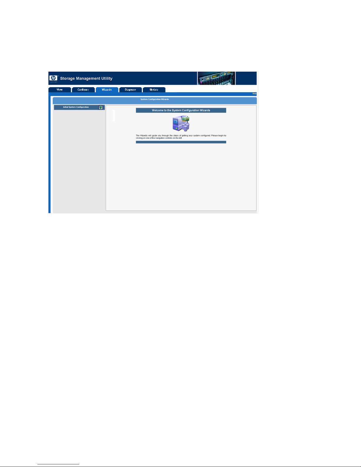
• The Wizard tab—includes the Initial System Configuration Wizard, which is the easiest and
simplest method for initially configuring the storage system. You are prompted in a logical
sequence for storage, iSCSI, logon, and management settings. The wizard then uses those settings
to configure the storage and make it available to the initiator. This configuration method is
best for single-server environments needing bulk storage, because one target is created, and is
assigned to one initiator. For information about using the wizard, see “Wizards”onpage69.
• The Configure tab—offers more flexibility than the wizard when configuring the storage.
This configuration method is best for multi-server environments that need to customize the
creation of storage LUNs and targets. For information about using the Configure tab, see
“Configure”onpage25.
14
Overview
Page 15
Accessing the SM
1. Install, connect, and apply power to the storage and other network devices, as detailed in your
system user doc
2. Obtain and record the IP address assigned to the primary management port (MA0). (Worksheets
may be provided with you system installation instructions.)
To determine t
through the messages until the following message is displayed on the controller LCD panel:
603 Port MA0 IP <address>
NOTE:
• If the IP addre
assigned to the management port. Check the cable connections, view the module LEDs,
and read the system installation, maintenance and service, or other user documents
for troubles
• If necessary, you can change the management IP address through
the controller LCD panel management menu. For more information, see
“Changing the managementport IP address through the MSA1510icontroller display panel”onpage16.
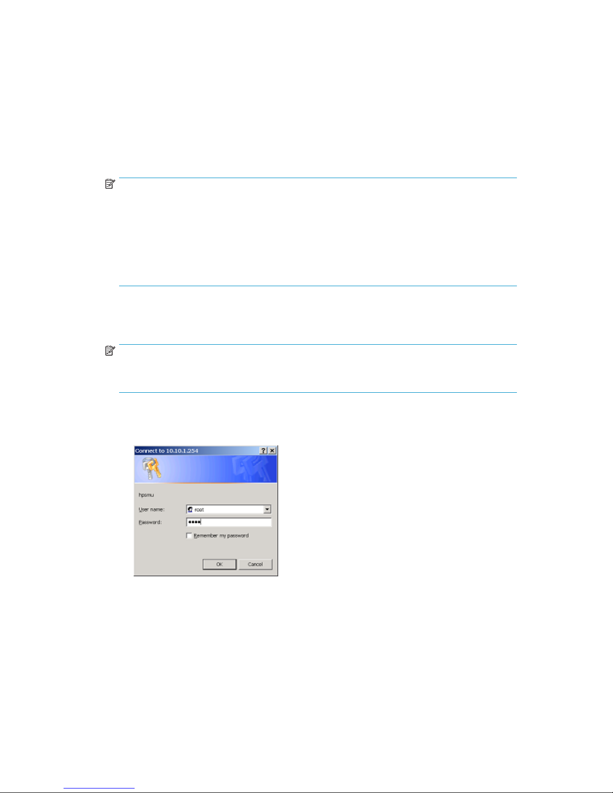
3. From a server or workstation with access to the storage device, open your Web browser and enter
the address obtained in Step 2.
For example: http://10.10.1.254
he IP address, press the arrow buttons on the front of the array controller and scroll
hooting information.
U
umentation.
ss message is not displayed on the LCD panel, an IP address was not
NOTE:
For additional security (at a reduced performance level), access the SMU using the secure
mode. For example: https://10.10.1.254
4. Enter the username and password. Default settings are:
•Username:root
•Password:root
HP Storage Management Utility user guide
15
Page 16
5. Wait a few moments for the utility to load.
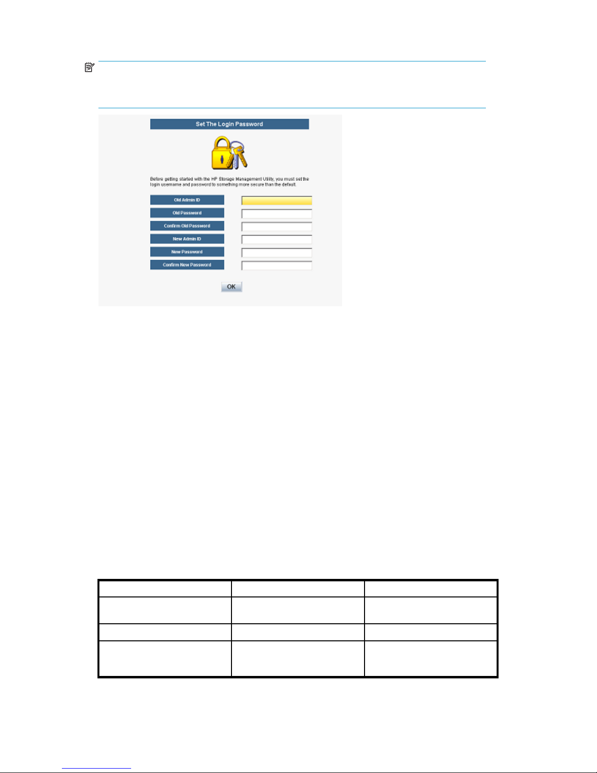
NOTE:
When accessing the SMU for the first time, a window is displayed requiring input of a
user-defined username and password.
6. One of the following happens:
• If key components of the system are unconfigured,aprompttogototheWizardtabis
displayed. (For more information, see “Wizards”onpage69.)
• If the system is partially configured, the Configure tab is displayed. (For more information,
see “Configure”onpage25.)
•Ifthesystemisconfigured, the View tab is displayed. (For more information, see
“Diagnose” on page 77.)
Changing the management port IP address through the
MSA1510i controller display panel
When the MSA1510i is initially installed and powered on, an IP address is automatically assigned to
the primary management port (usually MA0). Depending on your network configuration,thisdefaultIP
address may not be accessible by the network servers.
To change the IP address of the MSA1510i management port to be in the same LAN segment as the
network servers, do the following:
1. Access the controller LCD panel management menu. Press the right (>) navigation button on the
front of the active controller (usually the front-right controller.) Network Settings should be displayed
and blinking.
LCD panel navigation buttons work as follows:
Navigation button In the menu Within a menu option
Right (>) Select a blinking menu option.
When changing IP address
settings, move to the next digit.
Up/Down (^/v)
Left (<)
16 O v er v i ew
Scroll through the menu options.
Not applicable.
Change/Toggle a setting.
Accept the displayed setting and
return to the initial management
menu display.
Page 17

2. Disable DHCP.
a. With Network Settings displayed and blinking, press > to select it.
b. Press ^ or v until DHCP Enabled is displayed and blinking, and then press > to select it.
c. Press ^ or v to change the setting to No.
d. Press < to accept the new setting and return to the initial management menu display.
3. Change the IP address.
a. With Network Settings displayed and blinking, press > to select it.
b. Press ^ or v until IP Address is displayed and blinking, and then press > to select it.
c. Press ^ or v to scroll through and select the value for each digit of the IP address.
d. After entering all digits of the new IP address, press < to accept the new setting and return to the
initial management menu display.
4. Verify and, if necessary, change the Subnet Mask, Default Gateway, Primary DNS, Secondary DNS,
and VLAN ID using procedures similar to those outlined in step 3, but pressing ^ or v to navigate
to the desired menu option.
5. After all changes are entered, exit the management menu.
Press v until Exit is displayed and blinking, and then press >.
The LCD panel returns to the display mode.
6. Verify that the IP address was entered correctly by pressing ^ or v until the Port #MA0 IP message
is displayed.
7. Verify that the server can locate the MSA1510i by opening a command prompt window and using
the ping command.
Best prac
• Go to the HP storage website: http://www.hp.com/storage foryourarraycontroller. Product
website
• Hardware, firmware, and driver compatibility information.
•Firmwareand/orsoftware.
•System
• Use provided installation documents to gather items required for your installation, learn about the
installation process, and physically install devices.
• Record
is needed when configuring the storage, entering connection information, and setting up
multipathing; and for future configuration changes, reference, and troubleshooting purposes.
• Sign up with Subscriber's Choice to receive e-mail notifications and alerts about your HP devices:
h
• Sepa
Virt
• Ensure that initiators and targets are on the same Layer 2 Ethernet LAN. This guarantees the
integrity of the data traffic and maintains high network performance levels.
• Ensure the availability of the storage:
•Pro
•Pr
tices
s are updated to include the latest:
documentation.
information about your system in provided checklists and worksheets. This information
ttp://www.hp.com/go/e-updates.
rate management traffic from iSCSI storage traffic. Provide separate physical LANs or create
ual LANs (VLANs) to segment the traffic.
vide redundant power sources—Plug the two power supplies on the device into separate
interruptible Power Supplies (UPS) on separate sources of power. If you have only one UPS,
Un
maintain separate power paths by plugging one power supply to the UPS on one power
source and plug the other power supply to a separate power source.
ovide redundant data paths—Include two separate and isolated iSCSI storage networks
d the associated hardware (switches, MSA controllers, etc.) and software components
an
HP Storage Management Utility user guide
17
Page 18

(MPIO multipathing software, etc.) in the configuration. Configure targets using portals
on each controller.
• Create fault-tolerant logical storage units—Create LUNs using fault-tolerant RAID levels and
striping methods.
• When assigning system names and aliases, use only the following characters:
• Uppercase alpha characters (A-Z)
• Lowercase alpha characters (a-z)
•Numericcharacters(0-9)
• Special characters (! # = ( ) ‘ ; , . and space)
• When accessing the SMU, expand the browser to full screen or a minimum size of 1024 x 768
pixels. Other settings may distort the display or cause items to not display.
• When planning and configuring logical drives:
• Optimize performance and redundancy by striping the drives in the array across separate
storage enclosures on different SCSI buses, especially in mirrored environments using
RAID 1+0.
• Set the drive rebuild priority to high to minimize exposure during a drive failure.
• Customize the RAID level and striping method to the type of data that will be stored on the
logical drive.
NOTE:
Depending on the number of physical hard drives included in a storage unit, the SMU may suggest
RAID 6 (ADG) as the default RAID level, which offers a high level of fault tolerance and usable disk
capacity, but at a significant cost to I/O performance. For comparable fault tolerance but higher
performance, consider using RAID 1+0 when fault tolerance is desired and performance is more
important than usable capacity. Reserve RAID 6 (ADG) for situations when fault tolerance is desired,
but usable capacity is more important than performance.
• After configuring the storage, remember to:
• Verify that each initiator has been granted access to the target.
• Control access to the storage through the use of VLANs, CHAP authentication, and ACLs.
• Draw physical and logical diagrams of your network:
• Hardware/device diagram—Physical layout of the entire network, including device names
and cabling.
• Storage diagram—Hard drive and storage system configuration, including RAID levels.
• Path/Accessibility diagram—Access information, including which devices are allowed to
communicate with each other.
18 O ve r v ie w
Page 19
2View
The Storage Management Utility (SMU) View tab is used to view system information.
Included in this section:
•Pagedescription
•Availabletasks
Page description
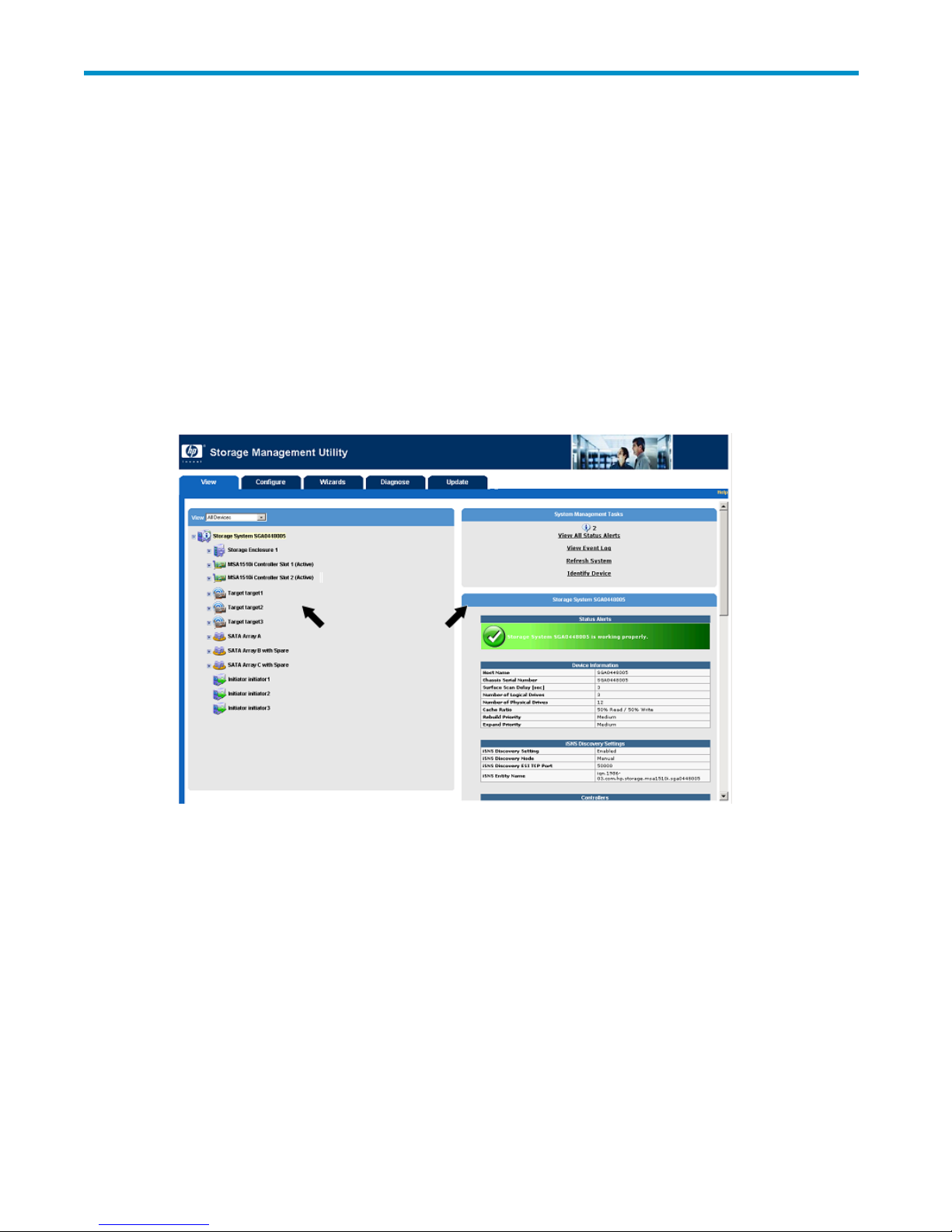
As shown in Figure 2, the page is divided into 2 main sections:
• System compo
• Task list (and display area)—Right side of page
nent list—Left side of page
Figure 2 View tab—showing the component and task lists
Tabs
Also shown in Figure 2 are the five tabs of the SMU:
• View—Fo
“View” on page 19”.)
• Configure—For initially configuring a system, entering new information, or changing existing
settings. (For more information, see “Configure” on page 25.)
• Wizard
“Wizards” on page 69”.)
• Diagnose—For generating an XML-formatted diagnostic report. (For more information, see
“Diag
rviewingdetailedconfiguration and status information. (For more information, see
s—For initially configuring a simple system. (For more information, see
nose” on page 77”.)
HP Storage Management Utility user guide
19
Page 20
Views
• Update—For updating MSA controller and module firmware. (For more information see
“Update”onpage79.)
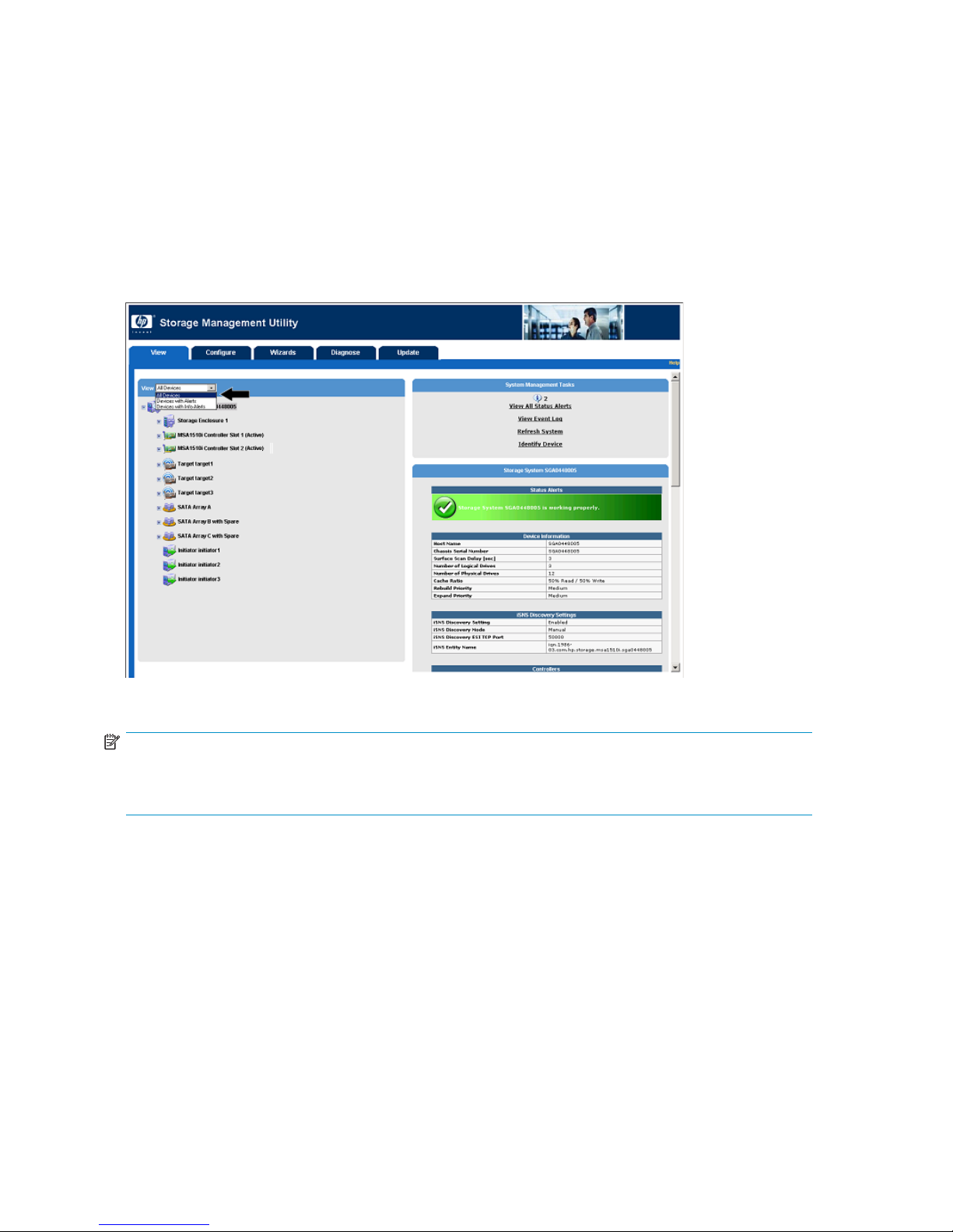
As shown in Figure 3, expand the View drop-down box to select a viewing option. Your selection
determines which system components are included in the component list:
• All Devices—D
• Devices with Alerts—Displays components for which any type of alert has been generated.
• Devices with Info Alerts—Displays components for which an informational alert has been
generated.
isplays all system components (Figure 2).
Figure 3 View tab—View drop-down box
NOTE:
• In any view, click+ or - to expand or contract the items in the system component list.
• As needed, click the
Available tasks
As shown in Figure 4, the View tab displays detailed system and status information for the selected
component.
scroll bar
on the right-side of the page to move through the displayed information.
20
View
Page 21
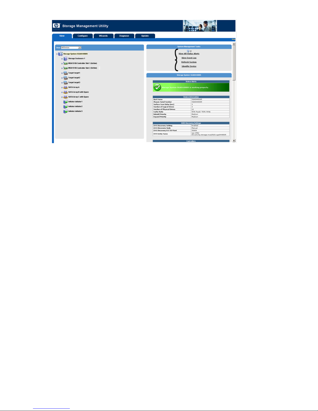
Figure 4 View tab—task listing
The following tasks are available in the View tab:
•Viewings
• Viewing the event log (View Event Log)
• Refreshing the display (Refresh System)
•Identify
tatusalerts(ViewAllStatusAlerts)
ing devices (Identify Device)
Viewingstatusalerts(ViewAllStatusAlerts)
Figure 5 illustrates some informational status alerts, generated when creating a logical drive.
HP Storage Management Utility user guide
21
Page 22

Figure5Viewtab—ViewAllStatusAlertspage
Viewing the event log (View Event Log)
Figure 6 shows an example of a system event log.
e 6 View tab—View Event Log page
Figur
Refreshing the display (Refresh System)
To refresh the SMU display, select Refresh System. The utility scans the configuration, and after a few
moments, updates the display.
22
View
Page 23

Identifying devices (Identify Device)
To locate a system component by lighting up its LEDs, select the item from the component list, and then
select Identify Device.
For example, if
in that logical drive are illuminated.
this task is selected for a logical drive, the LEDs on the physical hard drives included
HP Storage Management Utility user guide
23
Page 24

View
24
Page 25
3Configure
The Storage Management Utility (SMU) Configure tab allows for complete system configuration
and management. You can configure a new system, configure newly added components to an
already-configured system, and make changes to an already-configured system.
Included in this section:
•Pagedescription
•Availabletasks
• Sample configuration used in this document
• Fundamental tasks, in initial configuration sequence
•Securitytasks
• Additional management and configuration tasks
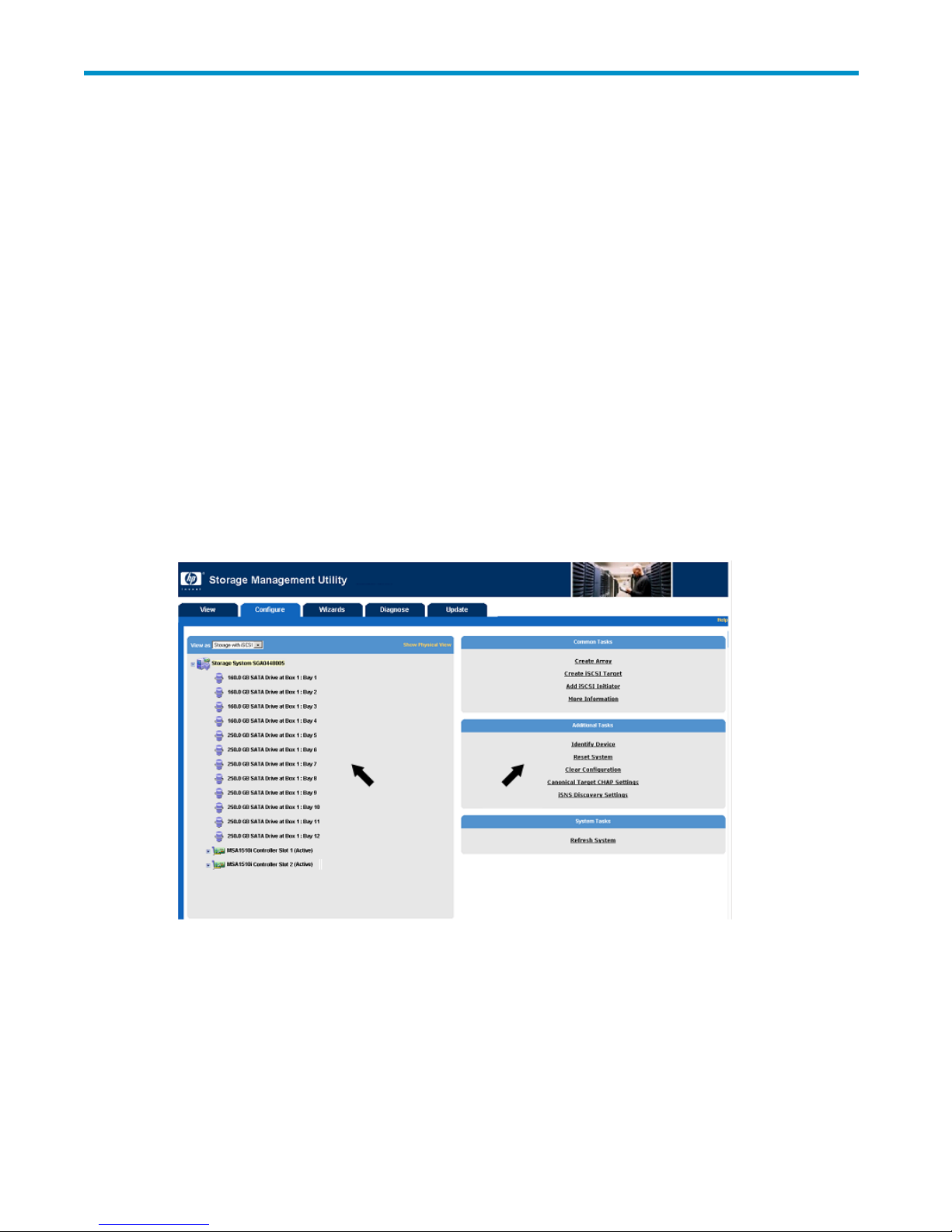
Page description
As shown in Figure 7,theConfigure tab is divided into 2 main sections:
• System component list—Left side of page
• Task list (
and input area)—Right side of page
Figure 7 Confi gure tab—showing the component list and task list
Tabs
Also shown in Figure 7 are the five SMU tabs:
• View—For viewing detailed configuration and status information. (For more information, see
“View” on page 19”.)
HP Storage Management Utility user guide
25
Page 26
Views
• Configure—For initially configuring a system, entering new information, or changing existing
settings. (For more information, see “Configure” on page 25.)
• Wizards—For initially configuring a simple system. (For more information, see
“Wizards” on page 69”.)
• Diagnose—For generating an XML-formatted diagnostic report. (For more information, see
“Diagnose” on page 77”.)
• Update—For updating MSA controller and module firmware. (For more information see
“Update”onpage79.)
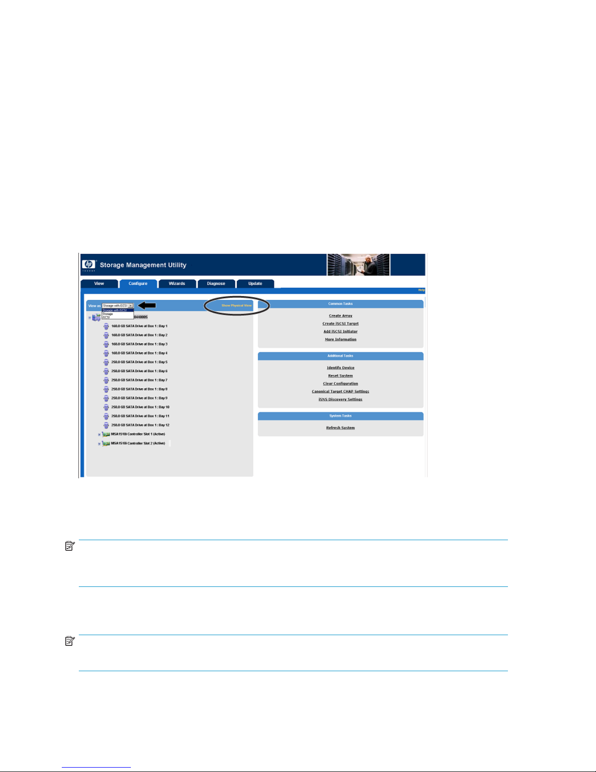
As shown in Fi
determines which system components are shown, as well as their associated tasks:
• Storage with iSCSI view—Displays all system components and their available tasks (Figure 8).
• Storage vie
• iSCSI view—Displays iSCSI-related items only; no arrays, logical drives, or hard drives are shown.
gure 8, expand the View as drop-down box to select a viewing option. Your selection
w—Displays storage-related items only; no targets or initiators are shown.
Figure 8 View as drop-down box
Also shown in Figure 8,clickShow Physical View/Show Logical View to control the display of the
configured storage.
NOTE:
TheShowPhysicalView/ShowLogicalViewtoggleaffectstheviewonlywhenstoragecomponents
are shown.
• Physical view—Displays a physical representation of the hard drives and configured storage.
• Logical view—Displays a logical representation of the hard drives and configured storage.
NOTE:
In any view, click + or - to expand or contract the items in the system component list.
26
Configure
Page 27
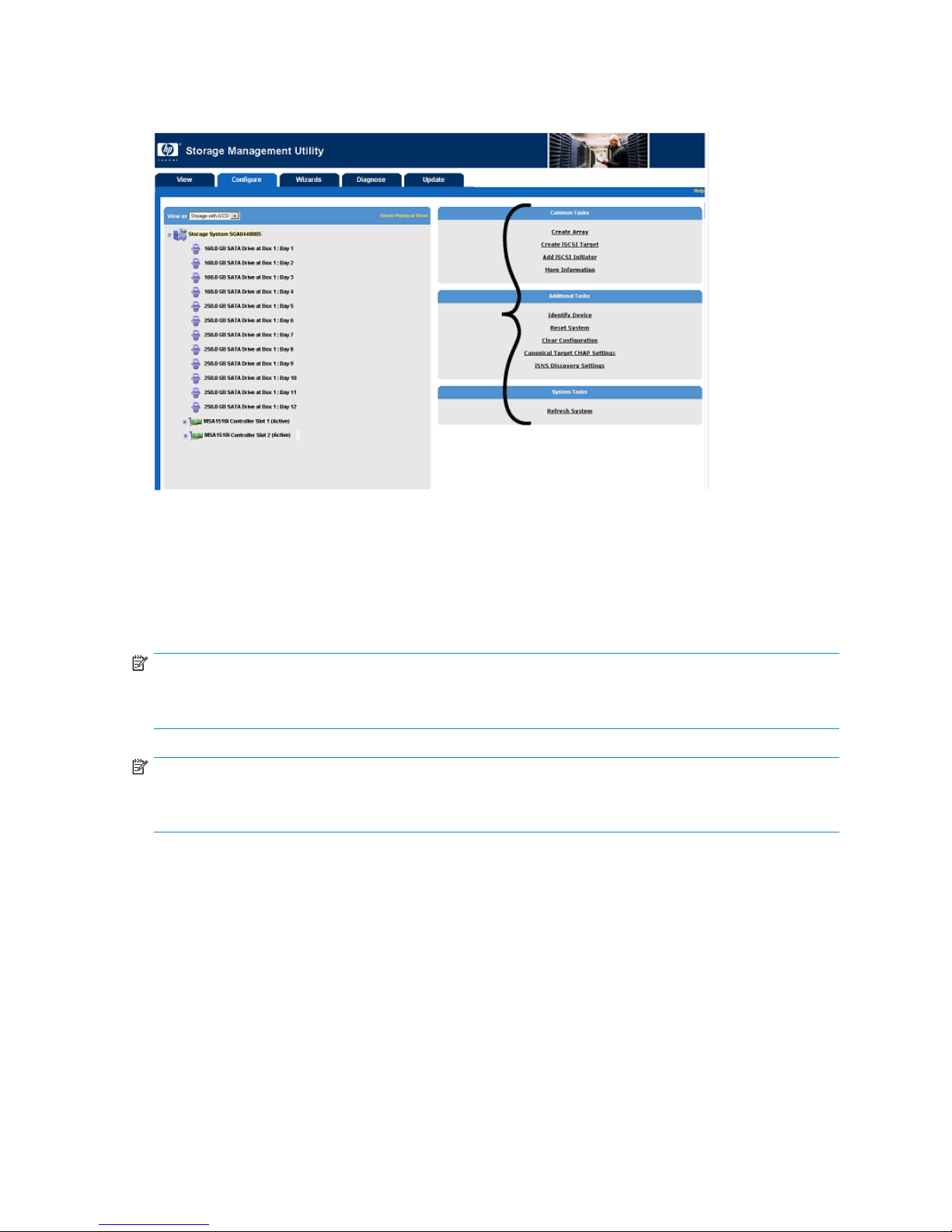
Available task
Figure 9 Configure tab—task listing
To perform a task in the SMU:
1. Select a sy
s
stem component from the list on the left side of the page.
2. Select a t
3. Enter th
NOTE:
After selecting a component from the system list, a unique task list for that component is displayed.
Table 2 lists the possible tasks for each system component.
NOTE:
More Information, Identify Device, Refresh System,andView All System Alerts are common tasks
and not repeated in Table 2.
ask from the list on the right side of the page.
erequestedinformation.
HP Storage Management Utility user guide
27
Page 28

Table 2 Available tasks, listed by system component
System
component
Top-level
storage system
Management
port
Available tasks Where documented
Create Array Creating arrays,page39
Create iSCSI Target
Add iSCSI Initiator Adding authorized initiators, page 49
Array Accelerator Settings
Storage System Settings
Reset System
Clear Configuration
Canonical Target CHAP Settings Setting up CHAP authentication,page53
iSNS Discovery Settings
Add iSNS Enabling iSNS discovery,page65
Redundancy Settings
Disable Controller Disabling a controller (Disable Controller), page 64
Management Port Settings
Management Port Login Settings
Set SSL Certificate Setting the SSL certificate, page 56
Creating stora
Changing array or logical drive characteri
stics, page 58
Changing global settings (Storage System
Settings),page61
Resetting the system (Reset System), page 66
Clearing the configuration (Clear Configur
ation), page 62
Enabling iSNS discovery,page65
Disabling
Settings)
Configuring the management port,page33
Not docum
ge targets, page 43
auto-path switching (Redundancy
,page64
ented
TELNET Service
SSH service
HTTP Service
HTTPS Service
SNMP Service
Data port
Data port IP
address
Portal Delete Portal Deleting a component (Delete), page 63
Unused space
Service Settings
Add Route Adding a route (Add Route),page58
Add IP Address
Enable/Disable Port Disabling data ports (Enable/Disable Port),page64
Create Portal
Delete IP Address Deleting a component (Delete), page 63
Create L
Spare Management
Delete Deleting a component (Delete), page 63
Expand
ogical Drive
Array
Not documented
Configuring data ports, page 35
Configuring data ports, page 35
g logical drives,page41
Creatin
Assigning spare drives to an array,page40
Changing array or logical drive characteri
stics, page 58
28
Configure
Page 29

System
component
Available tasks Where documented
Create Logical Drive Creating logical drives,page41
Array
Logical Drive
Target
Portal group
Mapped
Logical Drive
Spare Management
Delete Deleting a comp
Expand Array
Migrate RAID/Stripe size
Set Preferre
Create Portal Group Creating target portal groups, page 45
Map Logical Drive to Target Mapping logical drives to the target,page47
CHAP Settin
Delete Target Deleting a component (Delete),page63
Enable/Disable Access Control
Discovery Settings
Set Login Parameters
Assign Portals Assigning portals to the portal group,page46
Delete Portal Group Deleting a component (Delete),page63
Unmap Logical Drive from Target
Update Access Control Setting up Access Control Lists, page 51
dPath
gs
Assigning spare drives to an array,page40
onent (Delete),page63
Changing array or logical drive characteri
stics, page 58
Changing array or logical drive characteri
stics, page 58
Setting the p
Setting up CHAP authentication,page53
Setting up Access Control Lists, page 51
Enabling iS
Settings),
Changing target login parameters (Set Login
Parameters), page 62
Not documented
referred path (Preferred Path),page67
NS discovery of specifictargets(Discovery
page 66
Initiator
newpage p
Delete iSCSI Initiator Deleting a component (Delete),page63
CHAP Settings
Setting up CHAP authentication,page53
i
HP Storage Management Utility user guide
29
Page 30
Sample configur
ationusedinthisdocument
Illustrations
in this document demonstrate the process of configuring a dual-controller MSA1510i storage
system, with multiple targets being accessed by multiple initiators. Although each real-world environment
and the associated configuration steps will differ from this example, fundamental principles of the
configuration steps are the same for all installations. Your configuration may be more or less complex, but
the configuration steps will be similar to the steps outlined in this document.
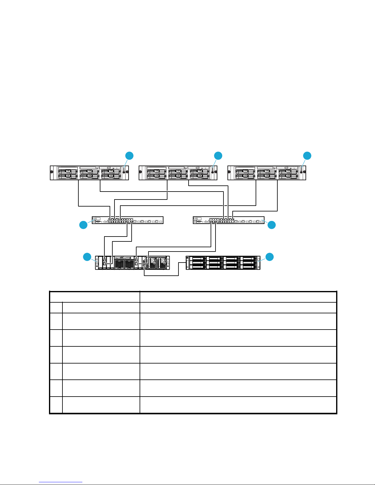
The following diagrams illustrate the sample configuration used throughout this document:
•Sampleconfiguration-Device and cabling diagram
•Sampleconfig
uration-physical-to-logical storage diagram
•Sampleconfiguration-Path/accessibility diagram
Sample configuration—Device and cabling diagram
5 6 7
15K
15K
15K
15K
15K
15K
15K
15K
15K
15K
3
15K
15K
15K
15K
15K
15K
15K
15K
4
1
Item
1
MSA1510i controller shelf
MSA20 SATA storage
2
enclosure
Primary Ethernet network
3
switch
Redundant Ethernet network
4
switch
5
Initiator A
Initiator B
6
7
Initiator C
2
15292
Description
Sample includes two array controllers and two 2-Port Ethernet iSCSI modules.
Sample includes twelve SATA hard drives.
Sample supports 100/1000BaseT functionality.
Sample supports 100/1000BaseT functionality.
Sample includes two 100/1000BaseT Ethernet NICs and cabling to the two
network switches.
Sample includes two 100/1000BaseT Ethernet NICs and cabling to the two
network switches.
Sample includes two 100/1000BaseT Ethernet NICs and cabling to the two
network switches.
30
Configure
Page 31

Sample configur
11 12 13
8 9 10
5 6 7
ation—Physical-to-logical storage diagram
2
1
Item
M S A 1510
1
MSA20 st
2
Array A
3ArrayB
4ArrayC
5
Logical Drive 1
6
Logical Drive 2
i controller shelf and
orage enclosure
3 4
Description
Sample includes two array controllers and two 2-Port Ethernet iSCSI modules,
with twelve SATA hard drives in the storage enclosure.
Uses hard drives from bays 1, 2, 3, and 4.
Uses hard drives from bays 5, 6, and 7, with number 11 assigned as a spare.
Uses har
Uses all space from Array A, with RAID 1+0 fault tolerance.
Uses all space from Array B, with RAID 5 fault tolerance.
15293
ddrivesfrombays8,9,and10,withnumber12assignedasaspare.
7
Logical Drive 3
8
Mapped Logical Drive 1
9
Mapped Logical Drive 1
10
dLogicalDrive1
Mappe
11 T a r g e t 1
12 T a rg e t 2
13 T a r g e
t3
Uses all
space from Array C, with RAID 5 fault tolerance.
When Logical Drive 1 was mapped to this target (Target 1), it was renamed
to Mapped Logical Drive 1.
When Logical Drive 2 was mapped to this target (Target 2), it was renamed
to Mapped Logical Drive 1.
When Logical Drive 3 was mapped to this target (Target 3), it was renamed
to Mapped Logical Drive 1.
HP Storage Management Utility user guide
31
Page 32

Sample configur
2 3
1
ation—Path/accessibility diagram
4 5
1
6 7
8 9
Port
1
MA0 10.10.10.254
2SA0 10.10.
3 S A 0 1 0 .1 0 .1 0 .11
4SA1
5
SA1
6 MB0 10.20.10.254
7
SB0 10.20.10.10
8SB0 10.2
9SB1 10.20.10.50
10 SB1 10.20.10.51
IP address Portals Portal group
10.10
10.10.10. 50
10.10.10. 51
0.10.11
15294a
Target
Not applicable Not applicable Not applicable
:1
1: 3 2 6 0
Portal
2: 3261
Portal
Portal 3: 3260
Portal 4: 3261
Portal 5: 3260
Portal 6: 3261
Portal 7: 3260
Portal 8: 3261
Not applicable Not applicable Not applicable
Portal 9: 3260
Portal 10: 3261
al 11: 3260
Port
al 12: 3261
Port
Portal 13: 3260
Portal 14: 3261
Portal 15: 3260
Portal 16: 3261
Group: 1
Group: 3
Group: 1
Group: 3
Group: 5
Group: 5
:5
Group
:5
Group
Group: 2
Group: 4
Group: 2
Group: 4
Group: 6
Group: 6
Group: 6
Group: 6
Target
:2
Target
Target: 1
Target: 2
Target: 3
Target: 3
t: 3
Targe
t: 3
Targe
Target: 1
Target: 2
et: 1
Targ
et: 2
Targ
Target: 3
Target: 3
Target: 3
Target: 3
32
Configure
Page 33

Fundamental ta
sks, in initial configuration sequence
Configuring a ne
•Configuring management and data ports
•Configuring hard drives
•Creatingstor
• Adding authorized initiators
w system includes the following tasks, performed in the following sequence:
age targets
Configuring management and data ports
As described in the installation documents, the array connects to the network switch from its Ethernet
iSCSI module.
IMPORTANT:
In dual-controller configurations, an additional Ethernet iSCSI module is installed in the chassis, providing
the redundant path to a separate iSCSI network switch. Ports on both modules must be configured.
When configuring management and data ports, consider the following:
• Isolate management trafficfromstoragetraffic, by assigning IP addresses in different LAN
segments.
• Assign one (or more) IP addresses to each port, and then assign one (or more) TCP portals
to each IP address.
• Enable/disable the following management services as needed for your environment:
• TELNET (default: disabled)
•SSH(default:enabled)
• HTTP (default: enabled)
•HTTPS(default:enabled)
• SNMP (default: enabled)
• Assign IP addresses and TCP portals to the data ports as outlined on your Path/Accessibility
Diagram. (When configuring the storage targets, each target is assigned to a specificgroupofIP
portals, controlling access to the storage and the flow of storage traffic.)
NOTE:
The maximum supported number of IP addresses and portals may differ, depending on the storage system
and the model of its supported array controller. See your system user documents for more information.
Configuring the management port
IMPORTANT:
Dual-controller configurations should configure the management port associated with each controller.
• The default management port for controller A is MA0.
• The default management port for controller B is MB0.
1. To clarify the display, expand the View as drop-down box and select the iSCSI view.
2. Expand (+) the component list for an installed MSA1510i controller.
HP Storage Management Utility user guide
33
Page 34

3. Select the Management Port on the controller and view the available tasks.
4. Select Man
agement Port Settings.
34
Configure
Page 35

5. Enter the settings for the management port.
NOTE:
• Port State must be
Enabled
(default) to use the SMU. If the management port state was
disabled,youmustusetheCommandLineInterface(CLI)tore-enableit.(Formore
information, see the Command Line Interface user guide.)
•AssignaHost Name to the storage system (default: chassis serial number). HP
recommends changing this to a more helpful user-defined value.
• Port Name MA0 is the default management port. Although other ports can be
configured as the primary management port, HP recommends configuring and using
the default.
• To control the path of management traffic to and from the array controller and to
add one level of system security, HP recommends assigning a static IP address to the
management port that is in a different LAN segment than the data ports. To assign
a static IP address, expand the DHCP Setting drop-down box and change the setting
to Disabled. The page expands (shown), showing the currently assigned IP address.
Change this to the address you want to use for management traffic. After changing the
IP address, you may need to re-connect to the SMU using the newly assigned IP address.
•Bydefault,VLAN ID is 0, meaning that traffic flowing from the port to the switch will be
untagged. ToassignaVLANforthisporttouse,enteritsvalue.VLANsaresetupon
theswitch,andareusedasonemethodofcontrollingaccesstothestoragesystem.
IMPORTANT:
For dual-controller configurations, repeat these steps to configure the management port on the other
controller.
• The default management port for controller A is MA0.
• The default management port for controller B is MB0.
Configuring data ports
Configuring each data port includes two steps:
• Assigning one or more IP addresses to the port (Step 1).
• Assigning one or more TCP portals to each IP address (Step 4).
IMPORTANT:
Configure all data ports you plan to use, including ports on the Ethernet iSCSI module associated
with the controller in slot 2, if installed.
HP Storage Management Utility user guide
35
Page 36

1. Select Data Port > Add IP Address.
2. Enter settings for the data port.
NOTE:
• To control the path of storage traffic to and from the array controller and to add one
level of system security, HP recommends assigning an IP Address to the data port that
is in a different LAN segment than the management port. This IP address can not be
changed
. To change an IP address assigned to a port, you must add a new IP address
and then delete the unneeded entry. When deleting an IP address, all corresponding
portals and portal group assignments are also deleted.
•Bydefau
be unta
on the s
lt, the VLAN ID is 0, meaning that traffic flowing from the port to the switch will
gged. To assign a VLAN for this port to use, enter its value. VLANs are set up
witch, and are used as one method of controlling access to the storage system.
3. When the display refreshes, expand (+) all components listed for the Data Port and verify that the
newly added IP address is shown in the component list.
36
Configure
Page 37

4. Select IP Address > Create Portal.
5. Enter settings for the portal.
NOTE:
For additional security, do not use commonly-known TCP ports.
6. When the display refreshes, verify that the newly configured portal is shown in the component list.
7. Asneededforyourenvironment,repeatStep 4 through Step 6 to assign additional TCP ports to
this IP address.
8. Repeat Step 1 through Step 7 to add additional IP addresses to this data port or to configure the
remainingdataports,suchasSA1,SB0,andSB1.
Sample configuration status - after configuring management and data ports
Figure 10 illustrates the current configuration.
The following items are configured:
• Management port MA0 and MB0
• DataportsSA0,SA1,SB0,andSB1
• Each data port is assigned two (2) IP addresses
•EachIPaddressisassignedtwo(2)TCPportals
HP Storage Management Utility user guide
37
Page 38

Figure 10 Sample configuration—after configuring management and data ports
NOTE:
Due to the limited screen size, information for the management and data ports associated with the
controller in slot 2 are not shown in Figure 10.
Configuring hard drives
Configuring hard drives includes two steps:
•Creatingarrays
• Creating logical drives
NOTE:
For more information on configuring the storage, see “Storage overview” on page 85.
38
Configure
Page 39

Creating array
1. Expand the View as drop-down box and select the Storage with iSCSI or Storage only view.
s
2. Select St
orage System > Create Array.
HP Storage Management Utility user guide
39
Page 40

3. Select the hard drives to include in the array.
NOTE:
• The SMU does not allow hard drives from SATA and SCSI storage enclosures to be
included in the same array.
• Harddrivesincludedinanarrayshouldbethesamesizeandspeed.Whendrivesizes
and speeds are mixed within an array, the usable capacity and the processing ability of
the array is reduced to that of the smallest and slowest hard drive.
• For optimum performance of an array, include hard drives from different storage
enclosures and connected to different SCSI buses on the array controller.
• Consider reserving some hard drives for use as on-line spares.
• For more information about configuring storage arrays, see
“Storage overview”onpage85.
4. When the display refreshes, verify that the newly configured array is shown in the component list.
5. Repeat Step 2 through Step 4 to configure additional arrays from any remaining unused hard drives.
Assigning spare drives to an array
HP recommends reserving some hard drives in your enclosures to be used as spare drives. Spares are
drives that are assigned to one or more arrays, but are not active members of those arrays. If a spare
is present and a physical drive in the array fails, the spare automatically replaces the failed drive as a
member of the array unit, and the process of rebuilding the information onto the spare automatically
begins. The system uses mirrored or parity information from the other member drives to reconstruct
information onto the spare drive. After the failed drive is replaced, data on the spare is automatically
copied to the replacement drive, and the spare is again available for use as a spare.
1. Select Array > Spare Management.
40
Configure
Page 41

2. Select the hard drive(s) to assign as a spare.
NOTE:
• Asparemustbethesametype(SATAorSCSI)asotherdrivesinthearray.
• A spare must be the same size (or larger) and speed (or faster) as other drives in the
array.
• A hard drive may be assigned as a spare to more than one array.
• If a spare is assigned to an array, the words
description.
3. Repeat Step 1 through Step 2 to assign spares to other configured arrays.
Creating logical drives
1. Select an Array with unused space, and then select Create Logical Drive.
with Spare
are included in the Array
HP Storage Management Utility user guide
41
Page 42

2. As needed, expand the drop-down boxes in the task area to change the settings from the suggested
defaults.
NOTE:
• The SMU suggests defaults for the logical drive, creating one large logical drive from all
unused space on the array, with the highest fault tolerance and performance possible
for the hard drives included in that array.
•OnlyFault Tolerance levels possible for the array are displayed. For example, RAID 5
is not listed if the array has only two physical hard drives.
•ThedefaultStripe Size gives optimum performance in a mixed read/write environment.
• For read-prominent environments, use a larger stripe size.
• For write-prominent environments, use a smaller stripe size for RAID 5 or
RAID_ADG,andalargerstripesizeforRAID0orRAID1+0.
• To build multiple logical drives on the same array, reduce the Size setting from the
default to a smaller amount. Additional logical drives can then be built from the
remaining unused space.
•DisablingtheArray Accelerator for a logical drive reserves use of the accelerator
cacheforotherlogicaldrivesinthearray. Thisfeatureisusefulifyouwanttheother
logicaldrivestohavethemaximumpossibleperformance.
3. When the display refreshes, verify that the configured logical drives are shown in the component list.
4. Repeat Step 1 through Step 3 to create additional logical drives for this array, or to create logical
drives for other arrays.
Configurationstatus-afterconfiguring hard drives
Figure 10 illustrates the current configuration.
The following items are configured:
• Management port MA0 and MB0
• DataportsSA0,SA1,SB0,andSB1
• Physical hard drives, into:
• Array A—Four (4) 160 GB hard drives, with no assigned spare
• Logical drive 1—RAID 1+0
• ArrayB—Three(3)250GBharddrives,withanassignedspare
• Logical drive 2—RAID 5
• Array C—Three (3) 250 GB hard drives, with an assigned spare
• Logical drive 3—RAID 5
42
Configure
Page 43

Figure 11 Sample configuration—after configuring hard drives
Creating storage targets
Configuring each storage target includes several steps:
•Creatingthetarget
•Creating
• Assigning portals to the portal group
• Mapping logical drives to the target
•Configur
NOTE:
This section illustrates the process of configuring an individual storage target. Repeat all steps in this
section for each target that you need to create.
Creating the target
1. Expand the View as drop-down box and select the iSCSI view.
target portal groups
ing the redundant controller for a target (dual-controller configurations only)
HP Storage Management Utility user guide
43
Page 44

2. Select Storage System and view the available tasks.
3. Select Cre
ate iSCSI Target.
4. Enter the requested information for the target.
NOTE:
• The utility suggests default values for the Target Name and Alias that adhere to iSCSI
standards. To accept the defaults, click OK.
•This
step creates the target entity; additional steps build information behind the target.
5. When the display refreshes, verify that the new target is shown in the component list.
44
Configure
Page 45

Creating target
1. Select Target > Create Portal Group.
2. Enter the requested information for the portal group.
portal groups
NOTE:
• The utility suggests a default Portal Group Alias. Acceptthedefaultorentera
user-defined value.
• This step creates the portal group entity; additional steps build information behind the
portal group.
3. When the display refreshes, expand (+) all components listed for the target and verify that the newly
added portal group is shown in the component list.
HP Storage Management Utility user guide
45
Page 46

Assigning porta
1. Select Portal Group > Assign Portals.
2. Expand the Port Name drop-down box and select the data port for this portal group to use.
ls to the portal group
3. Select the portals for this portal group to use.
NOTE:
• When assigning portals to a target's portal group, you are designating the path for
traffic to and from that target.
• Only IP addresses and portals associated with the selected data port are displayed.
• This example illustrates selecting two portals (on separate IP addresses) of data port
SA0.
4. When the display refreshes, expand (+) all components listed for the portal group and verify that the
newly assigned portals are shown in the component list.
46
Configure
Page 47

Mapping logical
1. Select Target > Map Logical Drive to Target.
2. Enter the requested information for the mapped logical drive.
drives to the target
NOTE:
• The utility suggests a default value for the Mapped LUN Alias.Acceptthedefaultor
enter a user-defined, content-descriptive value.
• The utility suggests a default number to assign to the mapping, beginning with number
1. Accept the default or expand the drop-down box to select a different number. HP
recommends accepting the default. The Mapped LUN number is the name presented
to the initiator.
• All available, unmapped logical drives are included in the selection list.
• One logical drive at a time can be mapped to a target. To map additional logical
drives to this target, repeat these steps.
3. When the display refreshes, verify that the mapped logical drive is shown in the component list.
4. To map additional logical drives to this same target, repeat Step 1 through Step 3 in this section.
Configuring the redundant controller for a target (dual-controller configurations only)
IMPORTANT:
Dual-controller configurations must create an additional portal group for each target, using portals on
the redundant Ethernet iSCSI module to establish a redundant path. Redundant data ports include SB0,
and SB1. For targets assigned to logical port SA0, use logical port SB0 as the redundant path. For
targets assigned to logical port SA1, use logical port SB1 as the redundant path.
The following steps are a summary of the steps included in Creating target portal groups and Assigning
portals to the portal group, but are for establishing a redundant path:
1. Create a portal group by selecting Target > Create Portal Group. Assign a name to the redundant
portal group.
HP Storage Management Utility user guide
47
Page 48

2. Select the newly created Portal Group > Assign Portals. Expand the Port Name drop-down box and
select a port on the redundant Ethernet iSCSI module for this target portal group to use. After the
portals associated with the selected logical port are displayed, select the TCP portals to use.
Configuration status - after creating storage targets
Figure 12 illustrates the current configuration.
The following items are configured:
• Management port MA0 and MB0
• Data por
• Physical hard drives, into arrays and logical drives
• Targets
•Target1
•Target2
•Target3
ts SA0, SA1, SB0, and SB1
48
Configure
Page 49

Figure 12 Sample system configuration—after configuring targets
NOTE:
Figure 12 illustrates the following for Target 1:
• One logical drive (Logical Drive 1) is mapped to this target.
• Primary and redundant paths are defined for this target:
• Portal Group “pg1” uses two portals on data port SA0 of the primary Ethernet iSCSI module.
• Portal Group “pg2” uses two portals on data port SB0 of the redundant Ethernet iSCSI module.
Adding authorized initiators
1. Select Storage System > Add iSCSI Initiator.
HP Storage Management Utility user guide
49
Page 50

2. Enter the requested information for the iSCSI initiator.
NOTE:
• The iSCSI Initiator Name is assigned when defining the initiator on the server, and is usually in the
format of “iqn.xxx”. Obtain initiator names from your network administrator or as displayed in the
iSCSI initiator software on the server.
• Be sure to enter the iSCSI Initiator Name exactly as assigned in the iSCSI initiator software on the
server. Include all special characters, including periods, and spaces. If the initiator name is entered
incorrectly,thetargetcannotbepresentedtotheinitiator.
• The system suggests a default value for the iSCSI Initiator Name Alias.Acceptthedefaultorentera
user-defined, descriptive value.
• Expand the iSCSI Initiator Profile Name drop-down box to identify the operating system of this
initiator.
Configuration status - after adding initiators
Figure 13 illustrates a completed configuration:
• Management port MA0 and MB0
• DataportsSA0,SA1,SB0,andSB1
• Physical hard drives, into arrays and logical drives
• Targets
• Initiators
•Initiator1
•Initiator2
•Initiator3
50
Configure
Page 51

Figure 13 Sample configuration—after adding initiators
IMPORTANT:
Perform the following tasks to complete the configuration:
• Enter secu
“Security tasks” on page 51.)
• Enter configuration settings in the iSCSI initiator configuration software utility (on the server),
includin
• Adding target portals for the initiator to access.
•Configuring the target portals. (Be sure to select the option to automatically restore the connection
• Logging on to establish an active session.
rity settings (optional, but recommended). (For more information, see
g:
each tim
e the system restarts.)
Security tasks
Security can include one or all of the following:
• Setting up Access Control Lists
• Setting up CHAP authentication
• Setting the SSL certificate
Setting up Access Control Lists
Access control lists (ACLs) provide security at the LUN level. In an ACL, you indicate the initiator(s) that
can access specific mapped logical drive units of a target.
NOTE:
Repeat all steps in this section for each target for which you want to establish an ACL.
1. From the server, open the iSCSI initiator software and close any active connections to the target. This
ensures that there is no I/O activity on the target.
HP Storage Management Utility user guide
51
Page 52

2. Select Target > Enable/Disable Access Control.
3. Expand the
ACL State drop-down box, and enable access control.
4. The following warning message is displayed:
5. Confirm that there is no active I/O on the target, and then click OK.
IMPORTANT:
• To prevent loss of access to the storage, ACLs should not be modified if there is an active
session between the initiator and the target. Before enabling ACL for a target, open
your iSCSI initiator software and verify that the target status is inactive or disconnected.
• When access control is
disabled
(default), all initiators with access to the array controller
can access the storage targets. (If CHAP authentication is set up, only initiators with
verified CHAP secrets can access the storage.)
• When access control is
enabled
, access to all mapped logical drives of the target is
immediately blocked (Step 2 through Step 3), until ACLs are created for each mapped
logical drive (Step 6 through Step 7).
52
Configure
Page 53

6. Select Mapped Logical Drive > Update Access Control.
NOTE:
Update Access Control is listed as a common task only if Access Control is enabled (Step 2).
7. Select the initiators that can access this mapped logical drive.
8. Repeat Step 6 through Step 7 for each mapped logical drive of the target.
9. If necessary, repeat Step 1 through Step 8 to set up an ACL for a different target.
Setting up CHAP authentication
The Challenge Handshake Authentication Protocol (CHAP) is one method of protecting access to the
storage. When using CHAP, the same password (also called secret) is entered in both the storage
management software and the initiator software.
When an initiator attempts to access the target, the CHAP secrets stored in both software utilities are
compared. If the secrets match, access is granted. If the secrets do not match, access is denied.
Three methods of CHAP authentication are available. Choose one method:
• Setting up storage-system target discovery CHAP authentication
• Setting up target-specific initiator-to-target CHAP authentication
• Setting up mutual CHAP authentication
Setting up storage-system target discovery CHAP authentication
Creating a CHAP secret that allows discovery of all targets in the storage system requires two steps:
• Assigning a CHAP secret that applies to the storage system (Step 1).
• Entering the same CHAP secret in the iSCSI initiator software (Step 4).
HP Storage Management Utility user guide
53
Page 54

1. In the SMU,selectStorage System > Canonical Target CHAP Settings.
2. Expand the
CHAP State drop-down box and change the setting to Enabled.
NOTE:
If Canonic
al Target CHAP settings have already been entered, the display is contracted
and protected by a gateway check box. To change existing CHAP settings, clear the Use
Existing CHAP Settings check box. The page expands, allowing access to the settings.
3. Enter the CHAP Secret in the provided spaces.
4. On the server, open the iSCSI initiator software utility. Navigate through the iSCSI utility and enter
the same canonical CHAP secret assigned in the SMU.
Setting up target-specific initiator-to-target CHAP authentication
Creating a CHAP secret that is unique for each target in the storage system requires two steps:
• Assigning a CHAP secret to each target (Step 1).
• EnteringthesameCHAPsecretintheiSCSIinitiatorsoftware(Step 4).
54
Configure
Page 55

1. In the SMU, select Target > CHAP Settings.
2. Expand the CHAP State drop-down box and change the setting to Enabled.
NOTE:
If CHAP settings have already been entered for this target, the display is contracted and
protected by a gateway check box. To change existing CHAP settings, clear the Use
Existing CHAP Settings check box. The page expands, allowing access to the settings.
3. Enter the CHAP Secret.
4. O n the server, open the iSCSI initiator software utility. Navigate through the iSCSI utility and enter
thesameCHAPsecretassignedintheSMU.
Setting up mutual CHAP authentication
Setting up mutual CHAP authentication between an initiator and a target requires:
• Entering a target-specificCHAPsecretinboththeSMUandtheiSCSIinitiatorsoftwareutility.
• Entering an initiator-specific CHAP secret in both the SMU and the iSCSI initiator software utility.
• Enabling mutual authentication in the iSCSI initiator software utility.
1. To enter a target-specific CHAP secret in both the SMU and the iSCSI initiator software utility, see
“Setting up target-specific initiator-to-target CHAP authentication” on page 54.
HP Storage Management Utility user guide
55
Page 56

2. To enter an initiator-specificCHAPsecretinboththeSMUandintheiSCSIinitiatorsoftwareutility:
a. On the server, open the iSCSI initiator software utility. Navigate through the iSCSI initiator
software utility and either assign a CHAP secret to the initiator or record the existing CHAP
secret.
b. In the SMU, select Initiator > CHAP Settings. Then, enter the same CHAP secret assigned to
the initiator the iSCSI initiator software utility.
3. On the ser ver, open the iSCSI initiator software utility. Navigate through the iSCSI initiator software
utility to locate and select the option to perform mutual authentication.
Setting the SSL certificate
ASecureSocketsLayer(SSL)certificate provides browser security, ensuring a secure connection between
the array controller and an initiating server, over which any amount of data can be sent securely. SSL
works by using a private key to encrypt data transferred over the internet.
The array controller ships with a default certificate already installed, but until a server-specific certificate is
installed, a warning message is displayed when accessing the SMU.
SSL certificate implementation on the MSA1510i makes use of PEM formatted files. Microsoft Certificate
ces do not directly support the PEM file format, but the publicly available OpenSSL toolset is
Servi
recommended for generating required keys and certificates or for converting Microsoft private key
exports into PEM format. For more information, see the HP Storageworks Modular Smart Array 1510i
Advanced Planning and Configuration Guide.
To upload your server-specificSSLcertificate:
56
Configure
Page 57

1. Select Management Port > Set SSL Certificate.
2. Expand the
3. Enter the requested information.
SSL Certificate Type drop-down box and select Upload PEM Certificate.
Additional management and configuration tasks
In addition to the tasks already described, the following tasks are also available:
• Adding a route (Add Route)
• Changing array or logical drive characteristics
• Disabling the array accelerator (Array Accelerator Settings)
• Expanding an array (Expand Array)
• Extending a logical drive (Extend Logical Drive)
• Migrating to a different RAID level or stripe size (Migrate RAID/Stripe Size)
• Changing global settings (Storage System Settings)
• Changing target login parameters (Set Login Parameters)
•Clearingtheconfiguration (Clear Configuration)
• Deleting a component (Delete)
• Disabling auto-path switching (Redundancy Settings)
• Disabling data ports (Enable/Disable Port)
• Disabling a controller (Disable Controller)
•EnablingiSNSdiscovery
• Enabling iSNS discovery (iSNS Discovery Settings)
• Enabling iSNS discovery of specific targets (Discovery Settings)
• Identifying devices (Identify Device)
• Refreshing the display (Refresh System)
• Resetting the system (Reset System)
• Setting the preferred path (Preferred Path)
• Viewing detailed component information (More Information)
• Viewing status alerts (View All Status Alerts)
HP Storage Management Utility user guide
57
Page 58

Adding a route (A
dd Route)
To add an entry t
1. Select a data port from the system component list, and then select the Add Route task.
2. Enter the IP information for the route.
o the route table for this controller:
Changing
Changes to existing storage arrays or logical drives include:
• Disabling the array accelerator (Array Accelerator Settings)
• Expandi
• Extending a logical drive (Extend Logical Drive)
• Migrating to a different RAID level or stripe size (Migrate RAID/Stripe Size)
NOTE:
To chan
Storage with iSCSI view.
array or logical drive characteristics
ng an array (Expand Array)
ge storage-related settings, expand the View as drop-down box and select the Storage or
58
Configure
Page 59

IMPORTANT:
• Completion time of an array expansion, logical drive extension, or logical drive migration varies,
depending on the drive speed and type, system array controller settings, and existing storage
configuration. (Process times of 36 to 72 hours are common.)
• During an expansion, extension, or migration, access to the data is permitted, but at a reduced
performance rate.
• During an expansion, extension, or migration, the risk of data loss if a drive fails is increased.
• Only one expansion, extension, or migration process can take place at a time.
• To verify the progress status of an expansion, extension, or migration:
•Viewtheiconforthelogicaldrive.
• View the More Information task for the logical drive.
• View the Status Alerts messages.
Disabling the array accelerator (Array Accelerator Settings)
By default, the array accelerator is enabled for all logical drives. To choose which logical drives use the
array accelerator, select the top-level storage system from the system component list, and then select the
Array Accelerator Settings task. Then, select which logical drives will use the array accelerator.
NOTE:
Disabling the array accelerator for a logical drive reserves use of the cache for other logical drives on
the array. This feature is useful if you want the other logical drives to have the maximum possible
performance.
Expanding an array (Expand Array)
If unassigned physical hard drives are available or were recently added to a storage enclosure, you can
use this task to increase the storage capacity of an existing array.
After expanding an array to include the new hard drive(s), you can then use the additional storage
capacity to:
HP Storage Management Utility user guide
59
Page 60

• Create new logical drives on the array. (For more information, see
“Creating logical drives” on page 41.)
• Migrate the RAID level or stripe size of existing logical drives on the array (For more information,
see“Migrating to a different RAID level or stripe size (Migrate RAID/Stripe Size)”onpage60.)
• Extend the storage capacity of an existing logical drive on the array. ((For more information, see
“Extending a logical drive (Extend Logical Drive)” on page 60.)
To expand the capacity of an array:
1. Ensure that a known, good backup of the array is available.
2. Verify that the Expand Priority is set to Medium or High. (For more information, see
“Changing global settings (Storage System Settings)” on page 61.)
3. Select Array > Expand Array.
NOTE:
The Expand Array task is available only if unassigned physical hard drives are present in
thestoragesystem. Tobeaddedtoanarray,theharddrivemustbeofsimilartype(SATA
or SCSI), processing ability, and size as the hard drives already included in the array.
4. Select the physical hard drives to add to the array.
Extending a logical drive (Extend Logical Drive)
If unused space is available in an array, you can use this task to increase the storage capacity of an
existing logical drive on that array.
NOTE:
The Extend Logical Drive task is listed only if unused space is present in the logical drive's array. To
create unused, available space in the array:
•
Expandthearray.(Formoreinformation,see“Expanding an array (Expand Array)”onpage59.)
• Delete a different logical drive on that array to release that space for use. (For more information, see
“Deleting a component (Delete)”onpage63.)
To extend the capacity of a logical drive:
1. Ensure that a known, good backup of the array is available.
2. Verify that the Expand Priority is set to Medium or High. (For more information, see
“Changing global settings (Storage System Settings)” on page 61.)
3. Select Logical Drive > Extend Logical Drive.
4. Enter the new size of the logical drive.
Migrating to a different RAID level or stripe size (Migrate RAID/Stripe Size)
1. Ensur
2. Veri
e that a known, good backup of the logical drive is available.
fy that the Rebuild Priority is set to Medium or High. (For more information, see
“Changing global settings (Storage System Settings)” on page 61.)
60
Configure
Page 61

3. Select Logical Drive > Migrate Logical Drive.
4. Enter the new settings for the logical drive.
Changing global settings (Storage System Settings)
The default global settings are adequate for most environments. If needed, use this option to:
• Change th
• Change the priority of array expansions relative to normal operations.
• Change the priority of array rebuilds relative to normal operations.
To change the default global settings:
1. Select S
e ratio of memory allocated to read and write operations.
torage System > Storage System Settings.
HP Storage Management Utility user guide
61
Page 62

2. Enter the new values.
NOTE:
• The Cache Ratio determines the amount of memory allocated to read and write
operations. For improved performance, you may want to change this ratio to allocate
more memory to write operations, as high as 10% read/90% write.
•TheExpand/Rebuild Priority settings determine whether normal operations are
affected by an expansion or rebuild—changing these settings from the defaults may
affect system performance:
• A low priority has a minimal effect on normal operations, because the expansion
or rebuild process takes place only when the controller is not busy. However, there
is an increased risk of data loss if another physical drive fails before the process
is completed.
• A high priority has a greater effect on normal operations, because the expansion
or rebuild process has a higher priority than the normal operations. With more
system resources allocated to the expansion or rebuild process, the completion
time is reduced, also reducing the risk of data loss if another physical drive fails
before the process is completed.
• Before initiating an array expansion or logical drive extension, HP recommends
changing the corresponding priority setting to Medium or High.
Changing target login parameters (Set Login Parameters)
1. Expand the View as drop-down box and select the iSCSI or Storage with iSCSI view.
2. Select Target > Set Login Parameters.
3. Enter the new values.
Clearing the configuration (Clear Configuration)
Use this option to reset the storage system to its original, unconfigured shipping configuration. Depending
on the selected options, some or all of the configuration settings are changed back to the default values,
including array, logical drive, target, initiator, and port information.
62
Configure
Page 63

1. Select Storage System > Clear Configuration.
2. Select the configuration components to clear.
NOTE:
• Select all—Clears all iSCSI, storage, and management configuration settings.
•iSCSIConfiguration—Clears iSCSI configuration settings only.
• Management Configuration—Clears management configuration settings only.
•StorageConfiguration—Clears storage configuration settings only.
• When management settings are cleared, any changes to the management port IP
address are erased and a new IP address is assigned to the management port. To obtain
the new IP address, press the arrow buttons on the front of the array controller and scroll
through the LCD messages until the following message is displayed: 603 Port MA0
IP <address>. Record the new IP address, so that you can again access the SMU.
3. A warning message is displayed. Review the selected options and respond appropriately.
Deleting a component (Delete)
If necessary, the following components can be deleted:
• Arrays
• Logical drives
• Targets
• Mapped logical drives
• Initiators
• Data port IP addresses
• IP address portals
• Routes
• Target portal groups
To delete a component, select the component from the list, and then select Delete from the task list.
HP Storage Management Utility user guide
63
Page 64

NOTE:
Someofthecomponentsthatcannotbedeletedwhileinuseinclude:
• Removing a portal from a portal group
• Deleting a portal group
• Deleting a target
Disabling automatic path switching (Redundancy Settings)
NOTE:
This task is available for dual-controller configurations only.
1. Select Storage System > Redundancy Settings.
2. Expand the Preferred Path Mode drop-down box and select one of the following options:
• Automatic (default)—Based on I/O load, the system automatically determines and assigns the
optimal path (controller ownership) for each LUNs. If a path is manually specified for a LUN with
the Set Preferred Path task, it may subsequently be re-assigned by the system.
• Manual—The path for each LUN must be set manually with the Set Preferred Path task.
Disabling data ports (Enable/Disable Port)
By default, all ports on the Ethernet iSCSI module are enabled.
To disable or re-enable a port, select the port in the component list, and then select Enable/Disable Port.
Disabling a controller (Disable Controller)
When removing a controller for service, HP recommends first disabling the controller.
To disable a controller, select the controller from the component list, and then select Disable Controller.
64
Configure
Page 65

Enabling iSNS discovery
Enabling iSNS discovery of storage targets includes:
•EnablingiSNSd
•EnablingiSNSdiscoveryofspecific targets (Discovery Settings)
Enabling iSNS discovery (iSNS Discovery Settings)
1. Select Storage System > iSNS Discovery Settings.
iscovery (iSNS Discovery Settings)
2. Expand the drop-down boxes to enable iSNS discovery and enter other iSNS settings.
NOTE:
• If the storage system is in a separate LAN segment than the iSNS server, be sure to change the
iSNS Discovery Mode to Manual.
• After en
each ta
“Enabl
abling iSNS discovery for the storage system, you must enable iSNS discovery for
rget you want discovered through the iSNS process. (For more information, see
ing iSNS discovery of specific targets (Discovery Settings)”onpage66.)
HP Storage Management Utility user guide
65
Page 66

Enabling iSNS d
1. Select Target > Discovery Settings.
iscovery of specifictargets(DiscoverySettings)
2. Expand th
e drop-down boxes to Enable SLP and/or iSNS Discovery.
Identifying devices (Identify Device)
To locate a system component by lighting up its LEDs, select the item from the component list, and then
select Identify Device.
For example, if this task is selected for a logical drive, the LEDs on the physical hard drives included
in that logical drive are illuminated.
Refreshing the display (Refresh System)
Use thi
To refresh the SMU display, select Refresh System. The utility scans the configuration and, after a few
moments, updates the display.
s option to update the SMU display.
Resetting the system (Reset System)
Use this option to remotely reset (power cycle) the array controller.
To reset the array controller, select Storage System > Reset System.
The following warning message is displayed.
66
Configure
Page 67

Setting the pref
NOTE:
This task is available for dual-controller configurations only.
To manually (explicitly) set controller ownership of a LUN:
1. Select an already-configured logical drive from the system component list, and then select the
Preferred Path task.
erredpathforaLUN(PreferredPath)
Viewin
2. Expand the Preferred Path drop-down box and select a controller.
IMPORTANT:
If the Redundancy Setting mode is set to “Automatic”, path ownership may automatically switch
from one controller to the other, depending on the processing load, as the system attempts
to balance the processing load between the two controllers. To permanently set the path for
a LUN, the Redundancy Setting mode must be set to ’Manual”. For more information, see
“Disabling auto-path switching (Redundancy Settings)”onpage64.
g detailed component information (More Information)
To view
More Information. The following image illustrates sample information displayed for a target.
detailed information about a system component, select the desired component, and then select
HP Storage Management Utility user guide
67
Page 68

NOTE:
Make note of the icon displayed next to each system component. Icons provide at-a-glance status of
each component. (For more information about status icons, see “Icon descriptions”onpage91.)
Viewingstatusalerts(ViewAllStatusAlerts)
AvailableinboththeConfigure and View tabs, View All Status Alerts shows the following alerts:
• Informational
• Degraded
• Critical
The following image illustrates the informational status alerts generated during the configuration of
a logical drive.
68
Configure
Page 69

4Wizards
The Initial System Configuration Wizard is the easiest and simplest method to initially configure your
system. You are prompted in a logical sequence for storage, iSCSI, logon, and management settings.
The wizard then uses those settings to configure the storage as an iSCSI target and make it available
to the iSCSI initiator.
NOTE:
This configuration method is best for single-server environments needing bulk storage:
• One IP address is assigned to each data port.
• One target is created.
• One initiator is identified.
For more control over an initial configuration or to make changes to an existing configuration, use the
SMU Configure tab. (See “Configure” on page 25.)
To use the wizard:
1. Access the SMU. (For more information, see “Accessing the SMU” on page 15.)
2. When prompted, click OK to use the wizard.
NOTE:
•IftheConfiguretabisdisplayedinsteadoftheprompt,clicktheWizardstabtoaccess
the wizard.
• If the View tab is displayed instead of the prompt, the system is already configured and
the wizard is not available. Click the Configure tab to enter additions or changes to
the existing configuration.
• Portions of the Initial System Configuration Wizard are available in the following
circumstances:
•Ifthesystemiscompletelyunconfigured, all pages of the wizard are available.
• If IP addresses have not been assigned to the data ports, targets have not been
created, or initiators have not been added, the iSCSI Configuration page is
available.
• If IP addresses have not been assigned to the redundant data ports, the Redundant
iSCSI Configuration page is available.
• If there are unassigned physical hard drives or unused space in an array and iSCSI
settings have not been entered, the Storage Configuration page is available in
addition to the iSCSI Configuration page.
HP Storage Management Utility user guide
69
Page 70

3. In the initial Welcome page, expand the drop-down box on the left side of the page to display the
steps included in the wizard.
4. When prompted, click Next.
70
Wizards
Page 71

5. In the Storage Configuration page, enter configuration settings for the logical drive.
NOTE:
•ThewizardsuggestsaFault Tolerance (RAID) level, unique to each installation, based
on the detected number of storage enclosures, enclosure type (SATA or SCSI), number
of available hard drives, drive generation, speed, and size.
To select a different RAID level, expand the Fault Tolerance drop-down box.
• Depending on your hardware configuration and selected RAID level, the Assign Spare
option may not be displayed.
HP Storage Management Utility user guide
71
Page 72

6. In the iSCSI Configuration page, enter values for one of the data ports.
NOTE:
•Bydefaul
acceptin
t, the wizard recommends configuring Data Port SA0. HP recommends
gthedefault.
•AssignanIP Address to the data port.
• VLANs are set up on the switch and are used as one method of controlling access to the
storage. If using VLANs, enter the VLAN ID to use (0 = not used).
•Thewiza
the def
rd suggests a default iSCSI Target Name and iSCSI Target Alias.Accept
ault or enter user-defined values.
• BesuretoentertheiSCSI Initiator Name exactly as assigned in the iSCSI initiator
software utility (on the server). Include all special characters, including periods and
spaces. IftheInitiatorNameisenteredincorrectly,thetargetcannotbepresented
to the initiator.
•Indua
l-controller configurations, the Redundant iSCSI Configuration page is displayed,
er settings for a data port on the redundant module.
to ent
•Toconfigure the remaining data ports, complete the Initial System Configuration Wizard
process, and then use tasks available in the Configure tab. (For more information, see
“Configuring management and data ports”onpage33.)
72
Wizards
Page 73

7. In the Logon Settings page, specify if you want to change access information.
NOTE:
To change the logon username and password, clear Use Existing Administrator ID and
Password. The Logon Settings page expands, with options to change the Admin ID and
Password.
HP Storage Management Utility user guide
73
Page 74

8. In the Management Settings window, enter settings for the management port.
NOTE:
• Port Stat
you must u
e must be
se a Command Line Interface (CLI) command. For more information, see
Enabled
(default)tousetheSMU.Tore-enableSMUmanagement,
the Command Line Interface user guide.
•AssignaHost Name to the storage system. (Default: chassis serial number)
•Bydefau
managem
lt, the wizard suggests configuring Logical Port Name MA0 as the primary
ent port. HP recommends accepting the default.
• To control the path of management traffic to and from the array controller, and to
add one level of system security, HP recommends assigning a static IP address to the
management port
that is in a different subnet than the data ports
.ToassignastaticIP
address, expand the DHCP Setting drop-down box and change the setting to Disabled.
ge expands (shown), showing the currently assigned IP address. Change this to
The pa
dress you want to use for management traffic. After changing the IP address, you
the ad
may need to re-connect to the SMU, using the newly assigned IP address.
• VLANs are set up on the switch and are used as one method of controlling access to the
storage. If using VLANs, enter the VLAN ID to use (0 = not used).
74
Wizards
Page 75

9. After completing all steps of the wizard, a final confirmation window is displayed.
•ClickFin
ish to apply the configuration settings.
•ClickBack to change settings.
•ClickCancel to exit the wizard.
10. Wait for t
11 . After al
he utility to apply your settings.
l settings have been applied, you may need to change the IP address of your management
client device to be in the same subnet as the address assigned to the management port.
12. Access the ACU again, and navigate through the Configure and View tabs to familiarize yourself
with the interface, your initial configuration, and available options.
NOTE:
Wizards are available for basic configuration tasks only. Use the Manage and
Configure tabs to view and change your configuration. (For more information, see
“Configure”onpage25or“Diagnose” on page 77.)
IMPORTANT:
Perform the following tasks to complete the configuration:
• Enter security settings (optional, but recommended). (For more information, see
“Security tasks” on page 51.)
•Enterconfiguration settings in the iSCSI initiator configuration software utility (on the
server), including:
• Adding target portals for the initiator to access.
•Configuring the target portals. (Be sure to select the option to automatically restore
the connection each time the system restarts.)
• Logging on to establish an active session.
HP Storage Management Utility user guide
75
Page 76

76
Wizards
Page 77

5Diagnose
The Storage Management Utility (SMU) Diagnose tab is used to generate diagnostic information about
the array controller.
1. Click Generate Report.
HP Storage Management Utility user guide
77
Page 78

2. After a few moments, the report is displayed in a separate window.
3. As needed, use the options available in the report window menu bar to edit or save the diagnostic
information to a file.
78
Diagnose
Page 79

6Update
Updating system firmware (Flash Firmware)
Available tasks
As shown in Figure 14, the Update tab includes two options:
• Updating MSA fi
• Updating hard drive firmware
rmware
Figure 14 Update tab—task listing
Prerequisites
Before updating system firmware,makenoteofthefollowing:
• When determining which MSA controller firmware version to use, review the requirements and
information in the Compatibility Matrix(es), release notes, and other MSA announcements.
• Because firmware updates require least one restart of the MSA array and its attached storage
enclosures, update system firmware only during a scheduled maintenance window.
• Before updating system firmware, stop all host traffic to the array controller.
• Before updating system firmware, make sure that a recent, known good backup of all data on
the MSA array is available.
• Before updating system firmware,makesurethatacopyoftheconfiguration, including the iSCSI
IP addressing and portal information, along with the hard drive, LUN, and target information is
available.
HP Storage Management Utility user guide
79
Page 80

• If it has been more than six months since you restarted your MSA storage system, HP recommends
that you power-cycle the MSA (power off, and then power on) before updating the firmware to
ensure that you are working with a fresh system.
• For newly installed MSA, do not perform a firmware update until controller batteries are fully
charged.
• For existing MSA, do not perform a firmware update until you have confirmed that the “host
mode” or “profile” for each connection is correctly set. The host mode identifies the operating
system of each connection to the storage. Do not use the “default” setting. If the host mode is
not properly set, hosts may lose access to the storage or experience other difficulties after the
update. Depending on your operating system environment or user preference, the host mode is
set through the “connection” commands of the CLI or through the “ACL” settings of the SMU. For
more information, see the CLI or SMU user documents.
• In dual controller MSA1510i configurations, you MUST log off all redundant paths to the MSA
array prior to beginning a firmware update. The update will not succeed if redundant paths are
detected by the MPIO/DSM and may require multiple reboots to recover back to the original
firmware version. There could also be potential loss of connection of the Internet Explorer to the
management port if there are redundant paths during the flash update cycle.
• In dual controller MSA1510i configurations, only one of the two MSA controllers is updated
directly. The second MSA controller is updated (cloned) when the MSA is power-cycled near
the end of the updating procedure.
• Depending on the storage enclosure model attached to the MSA array (SATA or SCSI), you may
be able to update enclosure firmware or hard drive firmware through the MSA utility.
• After the update is complete, be sure to check the status of the MSA for unexpected issues.
After power-cycling the MSA array, verify the status of the connections, defined profile types,
redundancy settings, and storage configuration.
• After the update is complete, power cycle the MSA and all of its attached hard drive storage
enclosures to activate the new firmware.
IMPORTANT:
If you encounter any problems during the firmware update process, stop and contact HP technical
support. See “HP technical support” on page 11 for support contact information.
Updating MSA firmware
1. Determine which version firmware is currently installed on the MSA by using one of the following
methods:
• With the array controller powered on, press the arrow buttons on the front of the controller until
the following message is displayed:
00 Array Controller Firmware ver <version>.
•FromtheSMU,selectView MSA1510i Controller. Then, view the Device Information in the right
pane of the screen for the Firmware Version.
80
Update
Page 81

2. Obtain the latest firmware files and save to a temporary location on the host:
a. Go to the MSA1510i Support page: h
ttp://www.hp.com/support
b. Select your language.
c. Select your operating system.
The display is updated to include a list of available downloads for the specified operating system.
d. If you are not yet registered, under the Subscribe to driver and support alerts banner, click Sign
up now to receive e-mail notifications about MSA firmware or hardware, driver and support
alerts, advisories, and notifications. This alert notification system is a one-way broadcasting
method used to distribute important notices about HP devices.
e. Click the title description of the download option to display important information about the
update.
•ClicktheDescription tab for a brief overview about the download.
•ClicktheRelease Notes tab for detailed information about the download, including
version information, compatibility information, a summary of changes, important notes,
service considerations, and installation precautions.
IMPORTANT:
Besuretoreviewtheonlinereleasenotesandreadmefiles for last-minute notifications
about the update.
f. After reviewing the release notes for update, click Download and follow the on-screen instructions
to save the download bundle to a temporary directory on the server.
NOTE:
For downloaded ISO images, create a CD from the downloaded ISO file using a CD
burning tool with the ability to burn a CD from an ISO file. Do not simply copy the
ISO file to a blank CD.
3. Schedule a maintenance window for the update.
4. Ensure that there is a valid, recent backup of the system.
5. Stop al
lhosttraffictotheMSAarray.
6. If the MSA has not been restarted in the last six months, power cycle the array.
HP Storage Management Utility user guide
81
Page 82

7. From within the SMU, select Update > Controller > Flash Firmware.
8. Under the Flash Firmware banner, click Browse and navigate to the location of the previously-obtained
firmware file, and then click OK.
9. Wait for a completion message to display.
For example, the following messages are displayed on the MSA controller LCD panel:
M S A 1510 i u p d a t e s :
MSA20 updates:
307 FIRMWARE FLASH DONE
313 FIRMWARE FLASH DONE ON BOX <n>
(Each attached storage enclosure is updated one at a time, in sequential box number
order.)
NOTE:
Do not interfere with or cancel the download process. Interrupting the download process
might corrupt the firmware.
10. Restart the MSA and its attached storage enclosures storage system by doing the following (newly
downloaded firmware cannot be accessed until the MSA is restarted):
a. Press and hold down the MSA Power on/Standby button for approximately five seconds to
place the MSA in Standby mode.
b. Power off all storage enclosures attached to the MSA.
c. Wait approximately two minutes to ensure that the hard disk drives in the enclosures stop
rotating.
d. Restart all storage enclosures attached to the MSA.
e. Wait approximately four minutes to allow the enclosures to complete their startup routines.
f. Press and release the MSA Power on/Standby button to restart the MSA.
g. Wait (up to eight minutes) for the STARTUP COMPLETE message to display on the MSA
controller LCD panel.
82
Update
Page 83

11 . View the messages displayed on the array controller LCD panel during startup to confirm that the
firmware was installed successfully and that the array controller restarts successfully.
NOTE:
In dual-controller configurations, firmware on the two controllers is compared each time
the MSA chassis is restarted. If the versions are mismatched, the system prompts to clone
the firmware on the controller with the latest version over to the controller with the earlier
version firmware. (For the system to operate in a dual-controller mode, firmware on the
controllers must match.)
The following message is displayed on the LCD panel of the controller with the earlier
firmware:
07 CLONE FIRMWARE ? ‘<‘ = NO, ‘>’ = YES
Press the > button on the LCD panel to clone the firmware. During the cloning process,
informational messages are displayed on the controller LCD panels. When the cloning
process is complete, the just-updated controller automatically restarts.
Updating hard drive firmware
SCSI hard drive firmware updates are performed using files on the ProLiant Firmware Maintenance CD
and are required only when the following message is displayed on the MSA controller LCD panel:
85 BAD DRIVE FRMWARE BOX <n> BAY <n>
CAUTION:
Before downloading new firmware,makenoteofthefollowing:
• Update system firmware during a scheduled maintenance window.
• Stop all host traffic to the array controller during the updating process.
• Make sure that a recent, known good back up of all data on the MSA array is available before
updating system firmware.
• Make sure that a copy of the configuration, including the iSCSI IP addressing and portal information,
along with the hard drive, LUN, and target information is available before updating system firmware.
• If it has been more than six months since you restarted your MSA storage system, HP recommends
that you power-cycle the MSA (power off, and then power on) before updating the firmware to
ensure that you are working with a fresh system.
• After the update is complete, power cycle the MSA and all of its attached hard drive storage
enclosures to activate the new firmware.
• For newly installed MSA, do not perform a firmware update until the controller batteries are fully
charged.
1. ObtaintheISOimageforthelatestProLiantFirmwareMaintenanceCDfromthefollowingwebsite:
h
ttp://www.hp.com/support/proliantstorage. Then, burn the image onto a CD using a standard
CD-ROM burning utility. Do not simply copy the ISO file to a blank CD.
NOTE:
If the latest Firmware Maintenance CD does not include the latest-release drive firmware
contained in a Smart Component, the CD can be used in combination with the latest
individual Smart Component package to perform the update.
2. Insert the CD into the CD-ROM drive of the server.
3. Using the navigation window, locate the inventory file on the CD and copy it to a temporary location
on the host. The filename may be similar to InventoryResultsLinux.xml.
HP Storage Management Utility user guide
83
Page 84

4. Open a browser and access the SMU.
5. Select Update > Storage System > Flash Firmware.
6. Under the Upload Inventory Firmware XML File banner, click Browse, navigate to the location of the
previously-obtained XML firmware file, select an updating option, and then click OK.
7. Wait for the MSA1510i to process the XML file and update the display with a list of all Smart
Components that need updating.
8. In the updated display, select a Smart Component from the list.
9. Under the Upload Smart Component File banner, click Browse, navigate to the location of the Smart
Component firmware file on the CD, and then click OK. The system processes the Smart Component
and updates all hard drives, based on the list generated in Step 6. As the hard drives are updated,
progress information is displayed on the screen.
84
Update
Page 85

A Storage overview
W
• Arrays and logical drives
• Fault-tolerance levels
• Comparison of RAID Methods
•ChoosingaRAIDlevel
Arrays and logical drives
The capacity and performance of a single physical hard drive is adequate for home users. However,
business users demand higher storage capacities, higher data transfer rates, and greater protection
against data loss when a hard drive fails.
Connecting extra physical drives to a system increases the total storage capacity (Figure 15), but has
no effect on the efficiency of read/write operations. Data is still transferred to only one physical drive
at a time.
R/
D1 D2 D3
15310
Figure 15 Multiple physical drives (D1, D2, and D3) in a system
An array controller combines several physical drives into one or more virtual units called logical drives,
which have superior performance, capacity, and/or fault tolerant features than separate physical drives.
The read
require
/write heads of all included physical drives are active simultaneously, reducing the total time
d for data transfer.
R/W
L1
D1 D2 D3
15311
Figure 16 Multiple physical drives (D1, D2, and D3) configured into one logical drive (L1)
Because the read/write heads are active simultaneously, the same amount of data is written to each drive
g any given time interval. Each unit of data is called a block, and adjacent blocks form a set of
durin
data stripes across all physical drives in that logical drive (Figure 17).
HP Storage Management Utility user guide
85
Page 86

S1
B1
S2
B4
S3
B7
S4
B2
B5
B8
B11B10 B12
D2D1 D3
B3
B6
B9
15312
Figure 17 Data striping (S1-S4) and data blocks (B1-B12) on multiple physical drives
(D1, D2, D3)
For data in the logical drive to be readable, the data block sequence must be the same in every stripe.
This sequencing process is performed by the array controller, which sends the data blocks to the drive
write heads in the correct order.
A natural consequence of the striping process is that each physical drive in a given logical drive will
contain the same amount of usable space. If one physical drive has a larger capacity than other
physical drives in the same logical drive, the extra capacity is wasted, because it cannot be used by
the logical drive.
The group of physical drives containing the logical drive is called a drive array (or just array). Because all
physical drives in an array are commonly configured into just one logical drive, the term array is also
often used as a synonym for logical drive. However, an array can contain several logical drives, each of
adifferentsize(Figure 18).
A1
L1
L2
D1 D2 D3 D4 D5
Figure 18 Two arrays (A1, A2) containing five logical drives (L1 through L5) spread
across five physical drives (D1 through D5)
Each logical drive in an array is distributed across all of the physical drives within the array. A logical
drive can also extend across more than one storage enclosure attached to the array system.
Drive failure, although rare, is potentially catastrophic. For example, in Figure 18, failure of any one
physical drive in an array causes every logical drive in the array to suffer irretrievable data loss.
To protect against data loss due to physical drive failure, logical drives are usually configured with fault
tolerance.
Fault-tolerance levels
To protect against data loss due to physical drive failure, logical drives are usually configured with fault
tolerance. The following configuration types are available:
•RAID0—nofaulttolerance
• RAID 1+0—drive mirroring
• RAID 5—distributed data guarding
• RAID 6—advanced data guarding
A2
L3
L4
L5
15313
For any confi guration except RAID 0, further protection against data loss can be achieved by assigning a
drive as an online spare. This drive contains no data and is connected to the same controller as the
array. When any other physical drive in the array fails, the controller automatically rebuilds information
86 Storage overview
Page 87

that was originally on the failed drive to the online spare. The system is quickly restored to full RAID-level
data protection. (In the unlikely event that another drive in the array fails while data is being rewritten to
the spare, the logical drive will still fail.)
A spare is assigned to an array and is automatically assigned to all logical drives in the same array.
You do not need to assign a separate spare to each array; you can configure one hard drive to be
the spare for several arrays.
RAID 0—no fau
lt tolerance
This configuration (Figure 17) provides no protection against data loss when a drive fails. However, it is
useful for rapid storage of large amounts of non-critical data (for printing or image editing, for example),
or when cost is the most important consideration.
Table 3 RAID 0
features
Advantages Disadvantages
Highest performance method for writes.
Lowest cost per unit of stored data.
All drive capacity is used to store data (none needed
for fault tolerance).
RAID 1+0—drive mirroring
In this configuration, data on a physical hard drive is duplicated to a second hard drive.
NOTE:
When only two hard drives are included in the array, this fault-tolerance method is called RAID 1. When
more than two hard drives are included in the array, this fault-tolerance method is called RAID 1+0.
(RAID_1 is not supported on the MSA1510i storage system.)
Alldataonthelogicaldriveislostifaphysicaldrive
fails.
Cannot use a spare.
Can only preserve data by backing it up to external
storage media.
B1
B2
B3
B4
D1 D2
B1
B2
B3
B4
15314
Figure 19 RAID 1 array, with two physical hard drives (D1, D2)
When the array has more than two physical drives, drives are mirrored in pairs (Figure 20).
HP Storage Management Utility user guide
87
Page 88

S1
6
S2
B1
B5
B2
B6
B3
B7
B4
B8
D1
D5
S1
S2
B1
B5
D2
D6
B2
B6
D3
D7
B3
B7
D4
D8
B4
B8
15315
Figure 20 RAID 1+0 array, with eight physical hard drives (D1 through D8)
In each mirrored pair, the physical drive that is not busy answering other requests answers any read
request sent to the array. (This behavior is called load balancing.) If a physical drive fails, the remaining
drive in the mirrored pair can still provide all the necessary data. Several drives in the array can fail
without incurring data loss, as long as no two failed drives belong to the same mirrored pair.
RAID 1+0 is useful when high performance and data protection are more important than the cost of
physical drives.
Table 4 RAID 1, RAID 1+0 features
Advantages Disadvantages
Highest read and write performance of any
lerant configuration.
fault-to
No loss of data as long as no failed drive is mirrored
to another failed drive.
Expensive (half of the drives are used for fault
tolerance).
Only half of total drive capacity usable for data
storage.
RAID 5—distributed data guarding
In this method, a block of parity data is calculated for each stripe from the data that is in all other blocks
within that stripe. The blocks of parity data are distributed across every physical drive within the logical
drive (Figure 21).Whenaphysicaldrivefails,datathatwasonthefaileddrivecanbecalculatedfrom
the dat
or to a replacement drive in a process called a rebuild.
S1
S2
S3
S4
Figur
dist
This configuration is useful when cost, performance, and data availability are equally important.
a on the remaining drives and the parity data. This recovered data is written to the assigned spare
B1
B3
P5,6
B7
D1 D2 D3
B2
P3,4
B5
B8
P1,2
B4
B6
P7,8
1531
e 21 RAID 5 array, with three physical hard drives (D1, D2, D3) showing
ributed parity information (Px,y)
88 Storage overview
Page 89

Table 5 RAID 5 features
Advantages Disadvantages
High read performance. Relatively low write performance.
No loss of data if one physical drive fails.
More usable drive capacity than RAID 1+0, because
parity information requires the storage space
equivalent to one physical drive.
RAID 6—advanced data guarding
RAID 6 (also called RAID ADG) is similar to RAID 5, because both methods generate and store parity
information to protect against data loss caused by drive failure. With RAID 6, however, two different
sets of parity data are distributed across the physical drives, allowing data to be preserved even if
two drives fail. Each set of parity data uses up a capacity equivalent to that of one of the constituent
drives, as shown in Figure 22.
B1
B3
P5,6
Q7,8
B2
P3,4
Q5,6
B7
P1,2
Q3,4
B5
B8
Lossofdataifaseconddrivefailsbeforedatafrom
the first failed drive is rebuilt.
Q1,2
B4
B6
P7,8
Comp
D1 D2 D3 D4
15317
Figure 22 RAID 6 (ADG) array, with four physical hard drives (D1, D2, D3, D4) showing
distributed parity information (Px,y)(Qx,y)
This method is most useful when data loss is unacceptable, but cost is also an important factor. The
probability that data loss will occur when arrays are configured with RAID 6 (ADG) is less than when they
are configured with RAID 5.
Table 6 RAID 6 (ADG) features
Advantages Disadvantages
High read performance.
High data availability—Any two drives can fail
without loss of critical data.
More drive capacity is usable than with RAID
1+0—Parity information requires only the storage
equivalent to two physical drives.
Relatively low write performance (lower than RAID 5),
because of the need to create two sets of parity data.
arison of RAID Methods
e7summarizes important features of the different RAID levels.
Tabl
HP Storage Management Utility user guide
89
Page 90

Table 7 Summary of RAID methods
Alternative name
Usable drive
space*
Usable drive space
formula
Minimum number
of physical drives
Tolerates physical
drive failure?
Tolerates
simultaneous failure
of more than one
physical drive?
Read performance
Write performance
Relative cost
*Values f
• All physi
• Online sp
• No more t
• No more t
orusabledrivespacearecalculatedwiththeseassumptions:
cal drives in the array have the same capacity.
ares are not used.
han14physicaldrivesareusedperarrayforRAID5.
han 56 drives are used with RAID 6.
RAID 0 RAID 1+0
Striping Mirroring
100% 50% 67% to 93% 50% to 96%
n
1
No
No
High High High High
High Medium
Low
n/2 (n-1)/n (n-2)/n
23
Yes Yes Yes
Only if no two
failed drives are in
a mirrored pair
High Medium Medium
RAID 5 RAID 6
Distributed Da
Guarding (DDG)
No
Low Low
ta
Advanced Data
Guarding (ADG)
4
Yes
Choosing a RAID level
Use Table 8 to help you determine the best RAID level for your environment.
Table 8 Choosing a RAID level
Most important characteristic Also important Suggested RAID level
Fault tolerance
Cost effectiveness
I/O performance Cost effectiveness
Cost effectiveness
I/O performance
Fault tolerance
I/O performance
tolerance
Fault
RAID 6
RAID 1+0
RAID 6*
RAID5(RAID0iffaulttolerance
is not required)
RAID5(RAID0iffaulttolerance
is not required)
RAID 1+0
90 Storage overview
Page 91

BIcondescriptions
Table 9 describes SMU icons.
Table 9 SMU icons
Icon
Meaning
Top-level storage system
Controller—Active
Controller—Standby
Management or data port—Disabled
Management or data port—Enabled
IP address
Portal
Connection
Session
Route
Target
Mapped logical drive
Portal group
HP Storage Management Utility user guide
91
Page 92

Icon
Meaning
Initiator
Logical drive
Logical drive—Being expanded (animated icon)
Logical drive—Being rebuilt (animated icon)
SATA array
SATA hard drive
SATA hard drive—Spare
SATA hard drive—Active spare (animated icon)
SATA hard drive—Being rebuilt (animated icon)
SATA hard drive—Active spare—Being rebuilt (animated icon)
SCSI array
SCSI hard drive
SCSI hard drive—Spare drive
SCSI hard drive—Active spare (animated icon)
SCSI hard drive—Being rebuilt (animated icon)
SCSI hard drive—Active spare—Being rebuilt (animated icon)
Smart component
92
Icon descriptions
Page 93

Icon
Meaning
Status—Critical
Status—Degraded
Status—Okay
Status - Pause/standby
Help
More information is available for this component. View the status alerts.
HP Storage Management Utility user guide
93
Page 94

94
Icon descriptions
Page 95

Index
A
Access Control Lists (ACLs),51
access permissions, default settings,15
accessing SMU
first time,16
accessing the SMU,15
Add IP Address task, described,36
Add iSCSI Initiator task, described,49
advanced data guarding (See RAID 6.),89
alerts, viewing,21
array
characteristics, changing,58
creating,39
defined,86
expanding,59
online spares in,87
physical limitations of,86
recommendations,40
Array Accelerator
enabling/disabling for a logical drive,42
Array Accelerator Settings task, described,59
Assign Portals task, described,46
audience,9
B
best practices,17
block of data, defined,85
C
Cache Ratio,62
Canonical Target CHAP Settings task,
described,54,55
CHAP authentication
methods,53
setting up,53
mutual,55
storage-system target discovery,53
target-specific initiator-to-target,54
character set, supported,18
choosing an initial configuration method,14
Clear Configuration task, described,62
clearing the configuration,62
concluding configuration tasks,51
configuration
clearing,62
methods of,14
sample of,37,42,48,50
samples of,30
configuration, dual-controller
management port,35
configuration, installation
HP assistance,11
configuration, sample
device and cabling,30
path/accessibility diagram,32
storage diagram,31
Configure tab
adding initiators,49
assigning IP addresses to the data ports,36
assigning portals to the portal group,46
assigning spare drives to an array,40
assigning TCP ports to IP addresses,37
component list location,25
configuring the data ports,35
configuring the hard drives,38
configuring the management port,33
configuring the targets,43
creating arrays,39
creating logical drives,41
creating target portal groups
described,14,25
initial configuration tasks,33
mapping logical drives to targets,47
page description,25
performing tasks in,27
task list location,25
viewing options,26
configuring data ports,35
configuring management ports,33
configuring ports,33
configuring targets,43
configuring the hard drives,38
controller
route table
adding entry,58
conventions
text symbols,10
conventions and symbols
document,10
Create Array task, described,39
Create iSCSI Target task, described,44
Create Logical Drive task, described,41
Create Portal Group task, described,45
Create Portal task, described,37
,45
D
data block, defined,85
data port
assigning IP addresses to,36
configuring,33,35
data ports
additional security,37
HP Storage Management Utility user guide
95
Page 96

data protection methods (See also RAID levels.),
86
data stripes, defined,85
default access permissions,15
Delete task, described,63
deleting components,63
DHCP Setting,35,36
Diagnose tab
described,77
diagrams
hardware/device,30
path/accessibility,32
storage,31
Disable Standby Controller task, described,64
disabling the array accelerator,59
disabling the standby controller,64
Discovery Settings task, described,66
distributed data guarding (See RAID 5.),88
document
conventions and symbols,10
prerequisites,9
related documentation,9
documentation
HP website,9
providing feedback,11
drive array (See array.),86
drive mirroring (See RAID 1+0.),87
dual-controller configrations
Redundancy Settings task,64
dual-controller configuration
setting preferred path
LUN,67
E
Enable/Disable Access Control task, described,
52
Enable/Disable Port task, described,64
Ethernet connection
planning considerations,33
Ethernet iSCSI ports,33
event log, viewing,22
Expand Array task, described,59
Expand Priority,62
expanding an array,59
Extend Logical Drive task, described,60
extending a logical drive,60
F
fault tolerance
assigning to a logical drive,42
description of levels,86
fault tolerance (See RAID methods.),86
features of the SMU,13
firmware
downloading, notes about,83
MSA, updating,80
obtaining,81
updating, prerequisites,79
Flash Firmware task, described,79
flashing the firmware,79
H
hard drives
configuring,38
protecting against failure of,86
using spares,40
help
obtaining,11
Host Name,35
HP
technical support,11
I
Identify Device task, described,23,66
identifying devices,23,66
initial configuration,14
initial IP address,15
initial system configuration, concluding tasks,
51
initiator
access control lists,53
adding,49
CHAP settings,56
installation, configuration
HP assistance,11
installing the array controller,17
IP addresses
assigning TCP ports to,37
entering,36
obtaining the default,15
iSCSI Initiator Name,50
iSCSI view,26
iSNS Discovery Mode,65
iSNS Discovery Settings task, described,65
L
load balancing, defined,88
logical drive
characteristics, changing,58
logical drives
changing the RAID level or stripe size,60
compared to array,86
creating,41
defined,85
disabling the array accelerator,59
extending,60
granting access to,53
mapping to targets,47
size option,42
logical view,26
LUN
preferred path, setting,67
96
Page 97

M
management port
changing
through MSA1510i display,16
configuration , dual-controller,35
configuring,33,33
initial IP address,15
IP address
changing,16
settings,35
SSL certificate,57
Management Port Settings task, described,34
management traffic
control,74
management, configuration tasks
additional,57
Map Logical Drive to Target task, described,47
mapped logical drive
Alias name for,47
for a target,47
granting access to,53
Migrate RAID/Stripe Size task, described,60
mirroring of drives (See RAID 1+0.),87
More Information task, described,67
MSA
firmware, updating,80
MSA1510i controller display panel
IP address, changing,16
N
no fault tolerance (See RAID 0.),87
prerequisites,9
firmware, updating,79
priority settings,62
R
RAID 0 (no fault tolerance),87
RAID 1+0 (drive mirroring),87
RAID 5,88
RAID 5 (distributed data guarding),88
RAID 6 (advanced data guarding),89
RAID level
choosing a
table,90
summary
table,89
RAID methods
comparison table,89
RAID methods (See also fault tolerance.),86
RAID migration,60
rebooting the system, remote power cycle,66
Rebuild Priority,62
recommendations,17,33,40,41
Redundancy Settings task
described,64
redundant configurations
notes about,33,35,47,83
Refresh System task, described,22,66
refreshing the display,22,66
related documentation,9
Reset System task, described,66
route table
adding an entry,58
O
obtaining
MSA software or firmware,81
obtaining IP address of the management port,
15
online spare
defined,87
limitations of,87
overview information
storage,85
P
pagelayoutdescription,14
parity data
in RAID 5,88
in RAID 6,89
physical drives (See hard drives.),86
physical view,26
Port Name,35,46
portal groups
assigning portals to,46
creating,45
ports
described,33
enabling/disabling,64
S
sample configuration,30
after configuring initiators,50
after configuring management and data
ports,37
after configuring targets,48
after configuring the hard drives,42
security
Access Control Lists (ACLs),51
CHAP authentication,53
entering,51
initiator CHAP settings,56
SSL certificate,56
types of,51
Set Login Parameters task, described,62
Set SSL Certificate task, described,57
setting
LUN, preferred path,67
settings
management port,35
Size, of logical drive,42
HP Storage Management Utility user guide
97
Page 98

SMU
accessing,15
best practices,17
feature list,13
icons,91
overview,13
tab descriptions,25
SMU hard drive
RAID level,18
spare drives
assigning to an array,40
defined,87
recommendations,41
Spare Management task, described,40
SSL certificate, setting up,56
standby controller, disabling,64
storage
recommendations,40
viewing options,26
Storage System Settings task, described,61
Storage view,26
Storage with iSCSI view,26
Stripe Size,42
striping, described,85
Subscriber's Choice, HP,11
supported character set,18
symbols in text,10
system requirements,13
T
tab descriptions,19,25
target
changing the login parameters,62
configuring,43
enabling discovery of,66
task listing
Add IP Address,36
Add iSCSI Initiator,49
Array Accelerator Settings,59
Assign Portals,46
Canonical Target CHAP Settings,54,55
Clear Configuration,62
Create Array,39
Create iSCSI Target,44
Create Logical Drive,41
Create Portal,37
Create Portal Group,45
Delete,63
Disable Standby Controller,64
Discovery Settings,66
Enable/Disable Access Control,52
Enable/Disable Port,64
Expand Array,59
Extend Logical Drive,60
Flash Firmware,79
Identify Device,23,66
initial configuration sequence,33
iSNS Discovery Settings,65
Management Port Settings,34
Map Logical Drive to Target,47
Migrate RAID/Stripe Size,60
More Information,67
Preferred Path,67
Refresh System,22,66
Reset System,66
Set Login Parameters,62
Set SSL Certificate,57
Spare Management,40
Storage System Settings,61
Update Access Control,53
tasks, table listing of,27
TCP ports, entering,37
technical support
HP,11
service locator website,11
text symbols,10
98
U
Update Access Control task, described,53
Update tab
options,79
updating
MSA firmware,80
updating access control lists,53
updating system firmware,79
V
view
iSCSI view,26
logical,26
physical,26
Storage view,26
Storage with iSCSI,26
Page 99

View tab
described,19
page description,19
viewing component information,67
viewing options,20
viewing system event log,22
viewing system status alerts,21
VLAN
best practice,17
ID,35,36
W
websites
HP ,11
HP documentation,9
HP Storage,9
HP Subscriber's Choice for Business,11
product manuals,9
Wizard tab
additional concluding tasks,75
availability of,69
described,14,69
HP Storage Management Utility user guide
99
 Loading...