

Page 1

HP 30-10022-01 loop switch user guide
Part number: 5697–5674
First edition: June 2006
Page 2

Legal and notice information
© Copyright 2006 Hewlett-Packard Development Company, L.P.
Hewlett-Packard Company makes no warranty of any kind with regard to this material, including, but not limited to, the implied warranties of
merchantability and fitness for a particular purpose. Hewlett-Packard shall not be liable for errors contained herein or for incidental or consequential
damages in connection with the furnishing, performance, or use of this material.
This document contains proprietary information, which is protected by copyright. No part of this document may be photocopied, reproduced, or
translated into another language without the prior written consent of Hewlett-Packard. The information is provided “as is” without warranty of any
kind and is subject to change without notice. The only warranties for HP products and services are set forth in the express warranty statements
accompanying such products and services. Nothing herein should be construed as constituting an additional warranty. HP shall not be liable for
technical or editorial errors or omissions contained herein.
Intel and Itanium are trademarks or registered trademarks of Intel Corporation or its subsidiaries in the United States and other countries.
Microsoft, Windows, Windows NT, and Windows XP are U.S. registered trademarks of Microsoft Corporation.
UNIX® is a registered trademark of The Open Group.
30-10022-01 loop switch user guide
Page 3

Contents
1 Introduction . . . . . . . . . . . . . . . . . . . . . . . . . . . . . . . . . . . . . . . . . . . . . . . . . . . . . . . . 5
Overview. . . . . . . . . . . . . . . . . . . . . . . . . . . . . . . . . . . . . . . . . . . . . . . . . . . . . . . . . . . . . . . . . . . . . . 5
Features . . . . . . . . . . . . . . . . . . . . . . . . . . . . . . . . . . . . . . . . . . . . . . . . . . . . . . . . . . . . . . . . . . . . . . 6
HP technical support . . . . . . . . . . . . . . . . . . . . . . . . . . . . . . . . . . . . . . . . . . . . . . . . . . . . . . . . . . . . . . 6
HP-authorized reseller. . . . . . . . . . . . . . . . . . . . . . . . . . . . . . . . . . . . . . . . . . . . . . . . . . . . . . . . . . . 6
Helpful web sites . . . . . . . . . . . . . . . . . . . . . . . . . . . . . . . . . . . . . . . . . . . . . . . . . . . . . . . . . . . . . . 6
2 Switch Installation. . . . . . . . . . . . . . . . . . . . . . . . . . . . . . . . . . . . . . . . . . . . . . . . . . . . 7
Installation Preparation . . . . . . . . . . . . . . . . . . . . . . . . . . . . . . . . . . . . . . . . . . . . . . . . . . . . . . . . . . . . 7
Switch Installation . . . . . . . . . . . . . . . . . . . . . . . . . . . . . . . . . . . . . . . . . . . . . . . . . . . . . . . . . . . . . . . . 7
Rack Installation. . . . . . . . . . . . . . . . . . . . . . . . . . . . . . . . . . . . . . . . . . . . . . . . . . . . . . . . . . . . . . . 7
Switch LEDs . . . . . . . . . . . . . . . . . . . . . . . . . . . . . . . . . . . . . . . . . . . . . . . . . . . . . . . . . . . . . . . . . . . . 7
Ethernet LEDs. . . . . . . . . . . . . . . . . . . . . . . . . . . . . . . . . . . . . . . . . . . . . . . . . . . . . . . . . . . . . . . . . 8
System LEDs . . . . . . . . . . . . . . . . . . . . . . . . . . . . . . . . . . . . . . . . . . . . . . . . . . . . . . . . . . . . . . . . . 8
Port LED . . . . . . . . . . . . . . . . . . . . . . . . . . . . . . . . . . . . . . . . . . . . . . . . . . . . . . . . . . . . . . . . . . . . 9
SFP Compatibility . . . . . . . . . . . . . . . . . . . . . . . . . . . . . . . . . . . . . . . . . . . . . . . . . . . . . . . . . . . . . . . . 9
Installing an SFP . . . . . . . . . . . . . . . . . . . . . . . . . . . . . . . . . . . . . . . . . . . . . . . . . . . . . . . . . . . . . . 9
Removing an SFP . . . . . . . . . . . . . . . . . . . . . . . . . . . . . . . . . . . . . . . . . . . . . . . . . . . . . . . . . . . . . . 9
Attaching a Device to the Switch . . . . . . . . . . . . . . . . . . . . . . . . . . . . . . . . . . . . . . . . . . . . . . . . . . 10
Booting the Switch and Attached Devices . . . . . . . . . . . . . . . . . . . . . . . . . . . . . . . . . . . . . . . . . . . . . . 11
3 Switch Management . . . . . . . . . . . . . . . . . . . . . . . . . . . . . . . . . . . . . . . . . . . . . . . . 13
Getting Started. . . . . . . . . . . . . . . . . . . . . . . . . . . . . . . . . . . . . . . . . . . . . . . . . . . . . . . . . . . . . . . . . 13
Configuring the Network Interface . . . . . . . . . . . . . . . . . . . . . . . . . . . . . . . . . . . . . . . . . . . . . . . . . 13
Connecting to the Web Manager . . . . . . . . . . . . . . . . . . . . . . . . . . . . . . . . . . . . . . . . . . . . . . . . . 14
Web Manager Overview . . . . . . . . . . . . . . . . . . . . . . . . . . . . . . . . . . . . . . . . . . . . . . . . . . . . . . . 14
Initial Switch Configuration . . . . . . . . . . . . . . . . . . . . . . . . . . . . . . . . . . . . . . . . . . . . . . . . . . . . . . 17
Frequent Switch Configuration Tasks . . . . . . . . . . . . . . . . . . . . . . . . . . . . . . . . . . . . . . . . . . . . . . . 18
Managing and Monitoring the Switch . . . . . . . . . . . . . . . . . . . . . . . . . . . . . . . . . . . . . . . . . . . . . . . . . 19
Viewing Switch Information. . . . . . . . . . . . . . . . . . . . . . . . . . . . . . . . . . . . . . . . . . . . . . . . . . . . . . 19
Configuring Switch Settings. . . . . . . . . . . . . . . . . . . . . . . . . . . . . . . . . . . . . . . . . . . . . . . . . . . . . . 21
Viewing the Event Log . . . . . . . . . . . . . . . . . . . . . . . . . . . . . . . . . . . . . . . . . . . . . . . . . . . . . . . . . 23
Viewing Port Information. . . . . . . . . . . . . . . . . . . . . . . . . . . . . . . . . . . . . . . . . . . . . . . . . . . . . . . . 27
Configuring Port Settings . . . . . . . . . . . . . . . . . . . . . . . . . . . . . . . . . . . . . . . . . . . . . . . . . . . . . . . 28
Viewing Port Diagnostics . . . . . . . . . . . . . . . . . . . . . . . . . . . . . . . . . . . . . . . . . . . . . . . . . . . . . . . 29
Viewing Advanced Statistics . . . . . . . . . . . . . . . . . . . . . . . . . . . . . . . . . . . . . . . . . . . . . . . . . . . . . 31
Managing Firmware . . . . . . . . . . . . . . . . . . . . . . . . . . . . . . . . . . . . . . . . . . . . . . . . . . . . . . . . . . 36
Configuring Date and Time Settings . . . . . . . . . . . . . . . . . . . . . . . . . . . . . . . . . . . . . . . . . . . . . . . . 37
Changing the Password . . . . . . . . . . . . . . . . . . . . . . . . . . . . . . . . . . . . . . . . . . . . . . . . . . . . . . . . 38
4 Technical Reference . . . . . . . . . . . . . . . . . . . . . . . . . . . . . . . . . . . . . . . . . . . . . . . . . 39
Troubleshooting Device Connections . . . . . . . . . . . . . . . . . . . . . . . . . . . . . . . . . . . . . . . . . . . . . . . . . . 39
Troubleshooting Management Connections . . . . . . . . . . . . . . . . . . . . . . . . . . . . . . . . . . . . . . . . . . . . . 39
Port Bypass Conditions and Recovery . . . . . . . . . . . . . . . . . . . . . . . . . . . . . . . . . . . . . . . . . . . . . . . . . 40
A Specifications . . . . . . . . . . . . . . . . . . . . . . . . . . . . . . . . . . . . . . . . . . . . . . . . . . . . . 41
Switch Specifications . . . . . . . . . . . . . . . . . . . . . . . . . . . . . . . . . . . . . . . . . . . . . . . . . . . . . . . . . . . . 41
Operating Conditions . . . . . . . . . . . . . . . . . . . . . . . . . . . . . . . . . . . . . . . . . . . . . . . . . . . . . . . . . . . . 41
B CLI Quick Reference . . . . . . . . . . . . . . . . . . . . . . . . . . . . . . . . . . . . . . . . . . . . . . . . . 43
Connecting to the CLI . . . . . . . . . . . . . . . . . . . . . . . . . . . . . . . . . . . . . . . . . . . . . . . . . . . . . . . . . . . . 43
Logging In and Out. . . . . . . . . . . . . . . . . . . . . . . . . . . . . . . . . . . . . . . . . . . . . . . . . . . . . . . . . . . . . . 43
Using the CLI . . . . . . . . . . . . . . . . . . . . . . . . . . . . . . . . . . . . . . . . . . . . . . . . . . . . . . . . . . . . . . . . . . 43
Frequent Switch Configuration Tasks . . . . . . . . . . . . . . . . . . . . . . . . . . . . . . . . . . . . . . . . . . . . . . . . . . 44
CLI Commands. . . . . . . . . . . . . . . . . . . . . . . . . . . . . . . . . . . . . . . . . . . . . . . . . . . . . . . . . . . . . . . . . 44
30-10022-01 loop switch user guide 3
Page 4

C Event Messages . . . . . . . . . . . . . . . . . . . . . . . . . . . . . . . . . . . . . . . . . . . . . . . . . . . 45
D AL_PA Cross References. . . . . . . . . . . . . . . . . . . . . . . . . . . . . . . . . . . . . . . . . . . . . . 49
Glossary . . . . . . . . . . . . . . . . . . . . . . . . . . . . . . . . . . . . . . . . . . . . . . . . . . . . . . . . . . 51
Index . . . . . . . . . . . . . . . . . . . . . . . . . . . . . . . . . . . . . . . . . . . . . . . . . . . . . . . . . . . . . 53
4
Page 5

1Introduction
This guide describes how to install and manage the 30-10022-01 loop switch.
Overview
The 30-10022-01 loop switch is a 12-port, speed agile switch. Enclosed in a 1U, half-rack form factor
enclosure, the switch is controlled by firmware loaded into the on-board flash mem ory. The switch is
designed as a central interconnect following the ANSI FC-AL standard. Devices are connected to the
switch through Small Form-factor Pluggable (SFP) transceivers and cables.
Each port independently supports 1 or 2 Gb/s of Fibre Channel bandwidth. Automatic port
configuration allows individual port access using automatic speed detection to connect devices based
on their supported speed. Smart synchronization validates proper initialization, checking signal
integrity and certain errors, such as OS and CRC, before allowing access to other Fibre Channel
devices. During normal operational when a change notification (LIP) is sent, the Bad Device
Recovery feature detects non-Fibre Channel compliant devices and removes them from participation.
Further validation continues to either bypass the port or allow access back into the Fibre Channel
network. Proper device notification is provided through the switch’s event log.
The switch also features automatic-configuration capability, which allows for IP address assignment
using DHCP- compatible networks. Once the switch is operational, complete switch configuration and
management is available through the intuitive, graphical-based Web Manager interface. In ad dition,
the switch features granular change notification management, retained system configuration
parameters, and a Command Line Interface (CLI).
30-10022-01 loop switch user guide 5
Page 6

Features
The 30-10022-01 loop switch incorporates the following features:
• High Performance Fibre Channel Switching:
• 2Gb/s or 1Gb/s auto-detection per port
• 12-port design with embedded SerDes
• Multiple simultaneous conversations between ports
• Traffic routed directly to destination ports
• Fairness and prioritization ensure that all devices have guaranteed access, or explicitly have prioritized
access over other devices in a system
• Automatic port configuration simplifies configuration and setup procedures
• Advanced diagnostics, performance monitoring, and fault isolation including continuous switch and
port monitoring and automatic bypass of problematic, or unused, ports
• Switch management using the embedded HTTP-based Web server, Command Line Interface (CLI), or
Telnet session
• Half-rack, 1U size for easy installation (optional rack-mounting kits available)
• Fibre Channel ANSI Standards Compliance
HP technical support
Telephone numbers for worldwide technical support are listed on the HP support web site:
http://www.hp.com/support/
.
Collect the following information before calling:
• Technical support registration number (if applicable)
• Product serial numbers
• Product model names and numbers
• Applicable error messages
• Operating system type and revision level
• Detailed, specific questions
For continuous quality improvement, calls may be recorded or monitored.
HP strongly recommends that customers sign up online using the Subscriber's choice web site:
http://www.hp.com/go/e-updates
• Subscribing to this service provides you with e-mail updates on the latest product enhancements, newest
versions of drivers, and firmware documentation updates as well as instant access to numerous other
product resources.
• After signing up, you can quickly locate your products by selecting Business support and then Storage
under Product Category.
HP-authorized reseller
For the name of your nearest HP-authorized reseller:
• In the United States, call 1-800-282-6672.
• Elsewhere, visit the HP web site: http://www.hp.com
telephone numbers.
.
. Then click Contact HP to find locations and
Helpful web sites
For other product information, see the following HP web sites:
• http://www.hp.com
• http://www.hp.com/go/storage
• http://www.hp.com/support/
• http://www.docs.hp.com
6Introduction
Page 7

2Switch Installation
Installation Preparation
After receiving the switch, perform the following steps to ensure that the switch and other contents
arrived safely.
To unpack the switch:
1. Inspect the outer shipping container for any damage that may have occurred in shipp ing.
Report any sign of damage to the appropriate shipping agency.
2. Remove the switch and cables from the shipping co ntainer; save the shipping container,
foam, and antistatic bags—returning the switch in any other container is not advised.
Make sure the following parts are included:
• 30-10022-01 switch unit
• RS-232 null-modem serial cable
•Power cable
• Self-adhesive pads (4)
3. Inspect the switch thoroughly. If any signs of damage are present, notify a sales
representative and/or the shipping agency.
Switch Installation
The switch can be installed in a rack or placed on a desktop.
Rack Installation
Guidelines for Mounting Equipment in a Rack
When installing equipment in a rack, give careful consideration to the following factors:
• The operating ambient temperature of rack-mounted equipment must not exceed the
maximum rated ambient temperature, which is indicated in this installation guide. (See
“Operating Conditions” on page 41.)
• The air flow clearances specified in this installation guide must be maintained within the rack.
(See “Operating Conditions” on page 41.)
• The AC supply circuit for rack-mounted equipment must be capable of supplying the total
current specified on all the labels of the rack-mounted equipment.
• All AC power supply connections must be properly earthed. To ensure the integrity of the
earth connection, special attention must be given to connections that are not directly
connected to the branch circuit (for example, power strips).
• The rack-mounting hardware has been carefully selected to properly support the equipment.
Any alternate rack-mounting hardware must provide equal or superior support.
• Plan the device installation starting from the bottom of the rack cabinet. Install the heaviest
device in the bottom of the rack cabinet.
For information on environmental requirements, see “Operating Conditions” on page 41.
Switch LEDs
The switch incorporates three sets of Light-Emitting Diodes (LEDs) to indicate Ethernet, switch, and
port status:
1. Ethernet LEDs – two separate LEDs indicating the network connection status.
2. System LEDs – three separate LEDs indicating the switch’s status.
3. Port LED – one multi-colored LED per port indicating the po rt’s status.
30-10022-01 loop switch user guide 7
Page 8
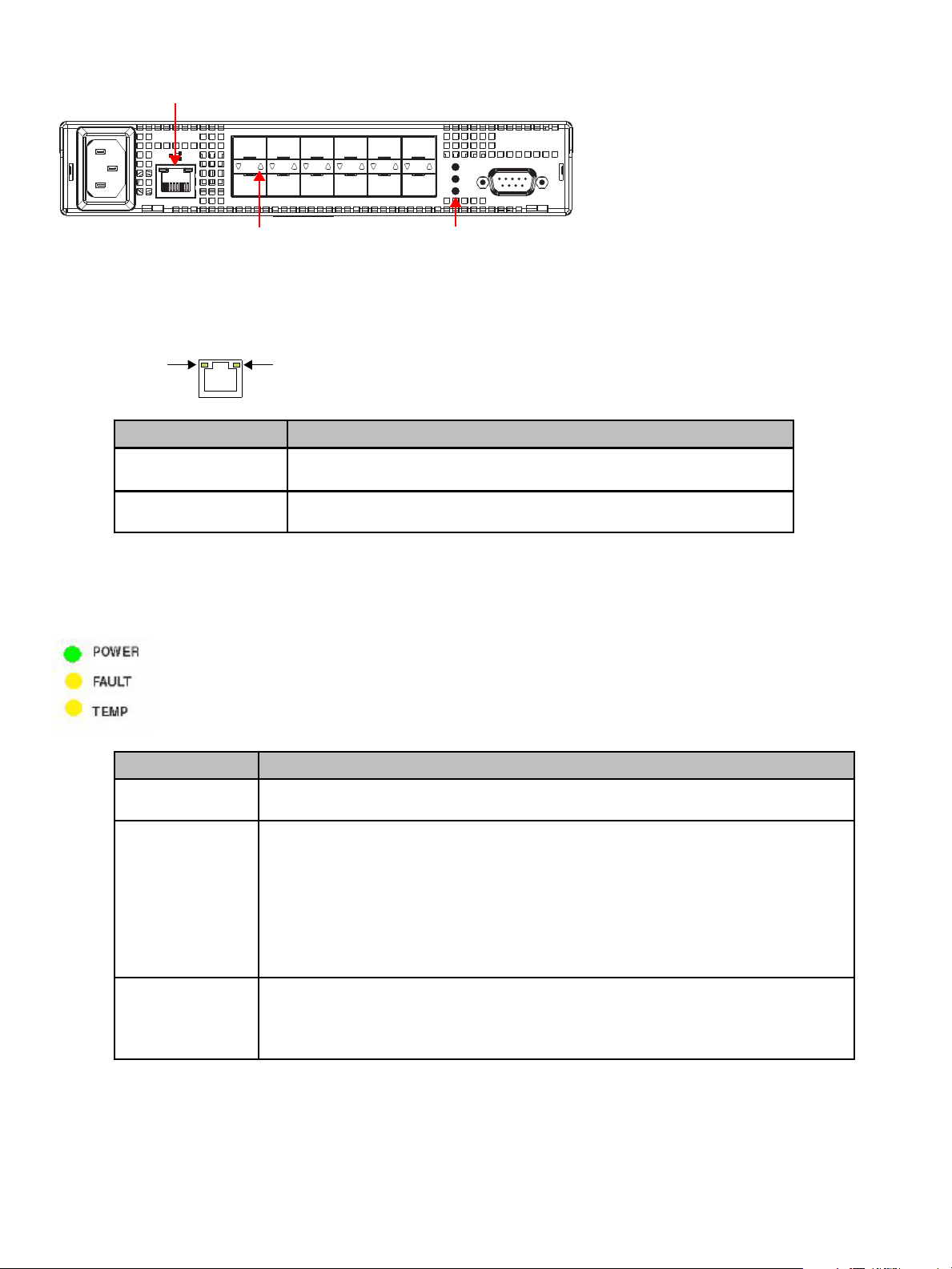
Figure 1 Switch View Depicting Ethernet, Port, and System LEDs
Ethernet LEDs
Z
100-240V~, 50/60 H
Ethernet LEDs
The Ethernet LEDs indicate the network connection status:
Figure 2 Ethernet LEDs
Ethernet Activity
Ethernet LEDs Indication
Ethernet Activity
(green LED)
Ethernet Link
(green LED)
System LEDs
The System LEDs indicate the switch’s status, independent of the port LEDs.
1
7
Port LED
3
2
9101112
8
Ethernet Link
5
4
6
POWER
FAULT
TEMP
System LEDs
10101
• When flashing, the Ethernet port is receiving data.
• When flashing rapidly, the traffic level is high.
When lit, the switch is connected to an operational Ethernet.
Figure 3 System LEDs
System LEDs Indication
Power
(green LED)
Fault
(yellow LED)
Temp
(yellow LED)
When lit, the switch is plugged in and the internal power supply is functional.
When lit, an event has occurred that meets or exceeds the current Fault LED threshold
setting. The default Fault LED threshold setting is “critical”. For more information on the
Fault LED threshold setting, see “Setting the Fault LED Threshold” on page 24.
complete list of event messages and severity levels, see
45
.
: Event Messages on page
For a
Note: The sw itch will continue to opera te. Switch functi onality may be imp aired depending
on the event that triggered the Fault LED. Regardless of the cause, the switch requires
immediate attention.
When lit, the internal temperature has exceeded acceptable levels.
Note: The sw itch will continue to opera te. Switch functi onality may be imp aired depending
on the event that triggered the Temp LED. Regardless of the cause, the switch requires
immediate attention.
8 Switch Installation
Page 9

Port LED
The Port LED indicates a port’s status.
Figure 4 Port LEDs
1
2
3
4
5
6
7
Port 7 LED Port 2 LED
8
Port LED Indication
Off SFP is not installed in the port.
On
(green)
On
(yellow)
Flashing
(green)
Normal port operational status when an SFP is installed and a link has been established.
The port has an SFP installed but a link has not been established.
Activity. Data is being transferred between the port and device.
SFP Compatibility
SFPs are “hot-pluggable” into the switch, which allows host computers, servers, and storage devices
to be added dynamically without requiring power removal from the switch or any connected devices.
The switch supports Small Form-Factor Pluggable (SFP) modules that comply with the SFP
specification as produced by the MSA consortium and have passed qualification testing.
The following manufacturers offer 4Gb, 2Gb, and 1Gb optical, shortwave SFPs in both RoHS and
non- RoHS versions:
• Intel
• Finisar
• JDS Uniphase
• Agilent
9101112
Installing an SFP
Plugging an SFP into the switch will automatically send a change notification to indicate that the
device is ready to begin initialization.
CAUTION: Forcing an SFP into a port may damage the SFP and/or port.
To insert an SFP:
1. Remove dust covers or plugs from the SFPs, if provided .
2. Slide the SFP into the port, ensuring cor rect polarity, until the latch clicks into place.
Removing an SFP
To extract an SFP:
Determine what kind of extraction mechanism the SFP has and remove the SFP a s follows:
• If the SFP has a removal tag, remove the cable from the SFP and then pull the removal tag outward
and toward the side of the SFP with the tag.
30-10022-01 loop switch user guide 9
Page 10

• If the SFP has a small plastic slider on the top or bottom, remove the cable from the SFP and then
push in the slider and hold while pulling out the SFP.
• If the SFP has a bale (small metal clasp), remove the cable from the SFP and then unlatch, pivot,
and pull the bale.
Attaching a Device to the Switch
To attach a device:
1. Make sure that the device is FC-AL compatible.
2. Attach a cable to the device.
3. Attach the other end of the cable to an SFP.
4. Make sure that the device and switch ar e operationa l and set to the same spe ed.
10 Switch Installation
Page 11

Booting the Switch and Attached Devices
The following procedure is recommended when booting the switch and attached devices.
To boot the switch and attached devices:
1. Power on the storage device s.
2. Insert the plug end of the switch’s power cord to a properly g rounded p ower source.
3. Insert the power cord’s IEC connector end into the switch’s power receptacle.
The switch powers on and runs Power-On Self-Test (POST) diagnostics to verify the
fundamental integrity of the switch ports. All switch LEDs turn on (LEDs illuminate). Then,
excluding the Ethernet Link and Power LEDs, the LEDs turn off (LEDs extinguish). Once the
switch is operational, the LEDs display current status as described in “Switch LEDs” on
page 7.
NOTE: The power cord’s IEC connector plug serves as the switch’s disconnect device. To cycle
power to the switch, remove and reconnect the switch’s power cord.
4. Power on any other switches connected to the SAN.
5. For certain applications, switch configuration must be co mpleted befo re contin uing with the
next step. For information regarding switch configuration, see : Switch Management.
6. After all switches have initialized, power on the hosts or storage contro llers.
The network initializes.
NOTE: FC-AL compatible nodes must perform initialization procedures upon power-up in order to
function properly. It is the responsibility of the Fibre Channel driver software on FC-AL nodes to
perform this initialization.
7. Check all port LEDs.
The network should be fully operational at this point. However, it is appropriate to ensure that
proper discovery has taken place and all required devices are participating in the network.
Some host bus adapters may provide this level of functionality or it might be resident in the
application software on the host operating system.
30-10022-01 loop switch user guide 11
Page 12

12 Switch Installation
Page 13

3 Switch Management
The switch incorporates two distinct interfaces for managing and monitoring purposes:
• The Web Manager interface provides an intuitive graphical user interface that enables users to quickly
check switch status or modify switch settings in a visual environment.
• The Command Line Interface (CLI) provides flexibility and additional functionality for advanced users.
For a list of CLI commands, see : CLI Quick Reference on page 43. For additional information on the
CLI, see the HP EVA 4000/6000/8000 30-10022-01 loop switch CLI reference guide.
While these interfaces provide nearly identical functionality, this guide describes how to use the Web
Manager interface for switch configuration and monitoring, unless otherwise noted.
Getting Started
This section explains how to configure the switch’s Ethernet network settings prior to using the Web
Manager. Once the switch’s network settings are configured, you can use the Web Manager for
switch configuration and monitoring.
Configuring the Network Interface
Before using the Web Manager, ensure that the switch’s Ethernet network parameter settings are
correct for the network configuration. The switch ships with the following default IP settings:
• IP Address: 192.168.0.10
• Netmask: 255.255.255.0
• Gateway: 192.168.0.1
To adjust these settings to open the Web Manager, connect to the switch using the provided
null-modem serial cable and enter the new network settings.
To connect through a serial interface:
1. Attach one end of the included null-modem cable to the co mputer’s RS-232 serial port and
attach the other end to the switch’s RS-232 serial port.
2. Open a terminal session through a serial termin al emulation program (su ch as
HyperTerminal®) with the appropriate serial port (for example, COM1) and the following serial
port parameters:
• Bits per second: 115200
• Data bits: 8
•Parity: None
•Stop bits: 1
• Flow control: None
3. If using HyperTerminal, press E
If using the tip command on a UNIX workstation, do the following:
a. View the /etc/remote file and create an alias similar to Hardware but with the serial
port parameters above (suggested name: Switch).
b. Use the tip command to establish a connection through the created alias, for
example tip switch.
4. Type li and press E
5. Type the password at the prompt and press E
6. From the serial terminal emulation pr ogram, type config network ip and press ENTER.
The switch’s current IP parameters are displayed with a prompt for entering the IP address.
7. Change the IP address and p ress E
8. Use the mask and gateway comman ds to change th e subnet ma sk and defau lt gateway,
respectively.
NTER.
NTER to receive a prompt.
NTER. The default password is “password”.
NTER.
30-10022-01 loop switch user guide 13
Page 14

9. Type save and press ENTER.
10. Type root reset and press E
11. Type y and press E
12. Attach the computer to the switch’s 10/100 Ethernet connector by doing one of the following:
• Attach an Ethernet RJ-45 cross-over cable directly between the computer and the switch.
• Attach two Ethernet RJ-45 twisted pair cables from the computer and the switch into an
operational Ethernet patch panel or hub.
DHCP IP Address Assignment
For Dynamic Host Configuration Protocol (DHCP)-enabled environments, you can enable the switch
to acquire an IP address from a DHCP server automatically. This feature is disabled by default.
To enable DHCP IP address assignment:
1. Use a serial terminal emulation program to connect to the switch as described in “Configuring
the Network Interface” on page 13.
2. Type the password at the prompt and press E
3. From the Root menu (root), type config network dhcp and press E
4. Enter 1 to enable DHCP and press E
NOTE: Once DHCP is enabled, the switch will automatically obtain an IP address from the DHCP
server. You will need to know this IP address in order to access the switch through the Web
Manager. You can locate the new IP address by attaching a serial cable and using a serial terminal
emulation program or contacting your network administrator.
NTER.
NTER to reset the switch.
NTER. The default password is “password”.
NTER.
NTER.
5. Type root reset and press ENTER.
6. Type y and press E
NTER to reset the switch.
Connecting to the Web Manager
The Web Manager displays current switch information, switch configuration settings, and port
information and utilization.
NOTE: The Web Manager supports Microsoft Internet Explorer® for Windows® version 5.5 or later,
Mozilla Firefox version 1.0 or later, and Netscape Navigator version 7.0 or later. The Web browser may
have pop-up blocking enabled, but the switch must have permission to use pop-ups for the Web Manager
functionality to work properly.
To connect to the Web Manager:
1. Ensure that the workstation has access to the network on which the switch is conn ected.
2. Open your Web browser.
3. In the address bar, type the switch’s IP address and press E
Web Manager Overview
The Web Manager enables you to view and configure switch and port settings using an intuitive,
graphical user interface. The main page is the Switch Information page. This page displays general
switch status and continually refreshes to display the most current switch status. For more
information on the Switch Information page, see “Viewing Switch Information” on page 19.
NTER.
14 Switch Management
Page 15
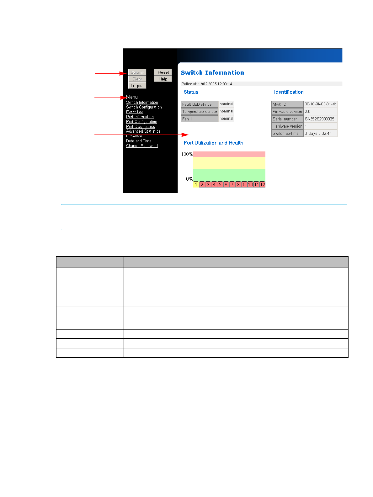
To return to this page at any time, click Switch Information on the navigation menu.
Figure 5 Web Manager interface
Command
buttons
Navigation
menu
Displayed
information
area
NOTE: The Web Manager’s appearance and information depends on the switch’s active firmware
version and may change without notice in subsequent firmware versions.
The Web Manager interface consists of a series of command buttons, a navigation menu, a nd the
displayed information area. The command buttons and navigation men u are present on e ach page.
Command Button Description
Submit Saves any changes made to the switch configuration. This button is disabled until a
Clear Clears entries that have not been submitted. This button is disabled until a
Logout Ends the current login session.
Reset Resets the switch.
Help Provides a link to online product documentation and firmware downloads.
Submitting Changes
The Web Manager does not require you to log into the switch unless changes are made to the
switch’s configuration. Any changes on a specific page must be submitted before proceeding to a
new page; otherwise, those changes will be lost.
configuration setting is changed or new information is entered. Click this button to
accept the configuration change.
Note: Any changes on a page must be submitted before proceeding to a new page;
otherwise, the changes will be lost.
configuration setting is changed or new information is entered. Click this button to
cancel the configuration change.
To submit a change:
1. Enter new info rmatio n or make changes to current settings.
2. Click Submit.
30-10022-01 loop switch user guide 15
Page 16
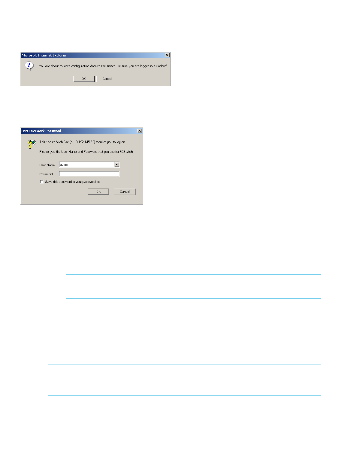
A message box is displayed confirming the change to the switch’s configuration and that you
are logged in as an administrator (“admin”).
Figure 6 Submit confirmation message box
3. Click OK.
The Enter Network Password box is displayed.
Figure 7 Enter Network Password message box
4. Ensure that “admin” is entered for the User Na me, and type the password in the Passwor d
field. The default password is “password”.
Note: If you have forgotten the password, contact an Emulex Technical Support representative for
5. Click OK to submit the change.
The page displays the submission update result, and should state that the configuration
change was updated successfully.
NOTE: To view the current page without displaying the submission results, click the View page
without submission results link.
Clearing Changes
The Clear button is disabled until a configuration setting is changed or new information is entere d.
To cancel a configuration change, click Clear.
Logging Out
To log out of the Web Manager, click Logout, or simply close the browser window.
NOTE: The Web Manager will automatically log users out after 15 minutes of inactivity, unless the Switch
Information page is displayed. The Switch Information page automatically updates to display the most
current switch status.
assistance.
Resetting the Switch
Changes to certain switch settings require that the switch be reset for those changes to occur. You
must be logged in to the Web Manager to reset the switch.
To reset the switch:
16 Switch Management
Page 17

1. Click Reset.
A message box confirming the switch reset is displayed.
2. Click OK.
The switch will reset.
Help
The Web Manager’s Help button provides a link to online product do cumen tation and firm ware
downloads available on the HP Web site (www.hp.com/go/852switch).
To access documentation and firmware, click Help.
Navigation Menu
The navigation menu provides a list of options for configuring and monitoring the switch. Clicking a
menu item displays the selected Web Manager page.
To ensure that the most current information is displayed, use the navigation men u instead of the
browser’s Back and Next buttons, which usually display cached copies and may not reflect curren t
switch information.
Initial Switch Configuration
Once a network connection has been established with the switch, use the Web Manager to perform
some basic switch configuration tasks:
• Verify the switch’s date and time settings.
• Change the switch’s password.
• Change the switch’s name.
For additional information on Web Manager features and functionality, see “Managing and Monitoring
the Switch” on page 19.
Step 1: Verify the Date and Time
During the initial Web Manager session, or anytime the switch is reset, the switch’s date and time will
automatically be set to the host system’s date and time. This information is displayed at the top of the
Switch Information page.
To change the current date or time, see “Configuring Date and Time Settings” on page 37 for
additional information.
Step 2: Change the Password
The default password is set at the factory to “password”. Change the default password to secure the
switch and guarantee that any configuration changes are only performed by registered users.
To change the password:
1. Click Change Password .
The Change Password page is displayed.
2. Enter the new password in the New Password text box.
NOTE: The password must be between 1 and 80 characters in length and is case sensitive.
3. Enter the new password again in the Con firm New Password text box.
4. Click Submit.
If you have not previously logged in to the switch, you will be prompted to do so. See
“Submitting Changes” on page 15 for additiona l information.
The page displays the submission update result, and should state that the password was
updated successfully.
30-10022-01 loop switch user guide 17
Page 18

NOTE: To view the current page without displaying the submission results, click the View page
without submission results link.
See “Changing the Password” on page 38 for additional information.
Step 3: Change the Switch Name
While not required, entering a switch name is recommended for identification and troubleshootin g
purposes.
To enter a switch name:
1. Click Switch Configuration.
The Switch Configuration page is displayed.
2. Under Switch Identification, enter the switch’s name in the Name text bo x.
3. Click Submit.
If you have not previously logged in to the switch, you will be prompted to do so. Se e
“Submitting Changes” on page 15 for additiona l information.
The new name is displayed in the Name text box and also appears in the title bar.
NOTE: The Web page may have to be refreshed before seeing the name change. Press CTRL+F5
to refresh the Web browser instance.
See “Viewing and Modifying Switch Information” on page 21 for additiona l information.
Frequent Switch Configuration Tasks
A list of frequent switch management and monitoring tasks is provided below. The list displays the
task, the corresponding Web Manager page, and a reference to where more information may be
found in this guide.
To… Click… In this guide, see...
View switch information Switch Information “Viewing Switch Information” on page 19.
Change general switch settings Switch Configuration “Configuring Switch Settings” on page 21.
Change the IP address Switch Configuration “Viewing and Modifying Network Configuration
View the event log Event Log “Viewing the Event Log” on page 23.
View port information Port Information “Viewing Port Information” on page 27
Change a port’s speed Port Configuration “Port Speed” on page 28
View port diagnostics Port Diagnostics “Viewing Port Diagnostics” on page 29
View port statistics Advanced Statistics “Viewing Advanced Statistics” on page 31
Upgrade the firmware Firmware “Managing Firmware” on page 36.
Change the date and time Date and Time “Configuring Date and Time Settings” on
Change the password Change Password “Changing the Password” on page 38
Settings” on page 21.
page 37
18 Switch Management
Page 19
Managing and Monitoring the Switch
The 30-10022-01 loop switch provides several option s fo r man aging, configuring, and monitoring the
switch to meet the needs of the network environment. This section describes the features an d
functionality of each Web Manager page available in the navigation menu.
Viewing Switch Information
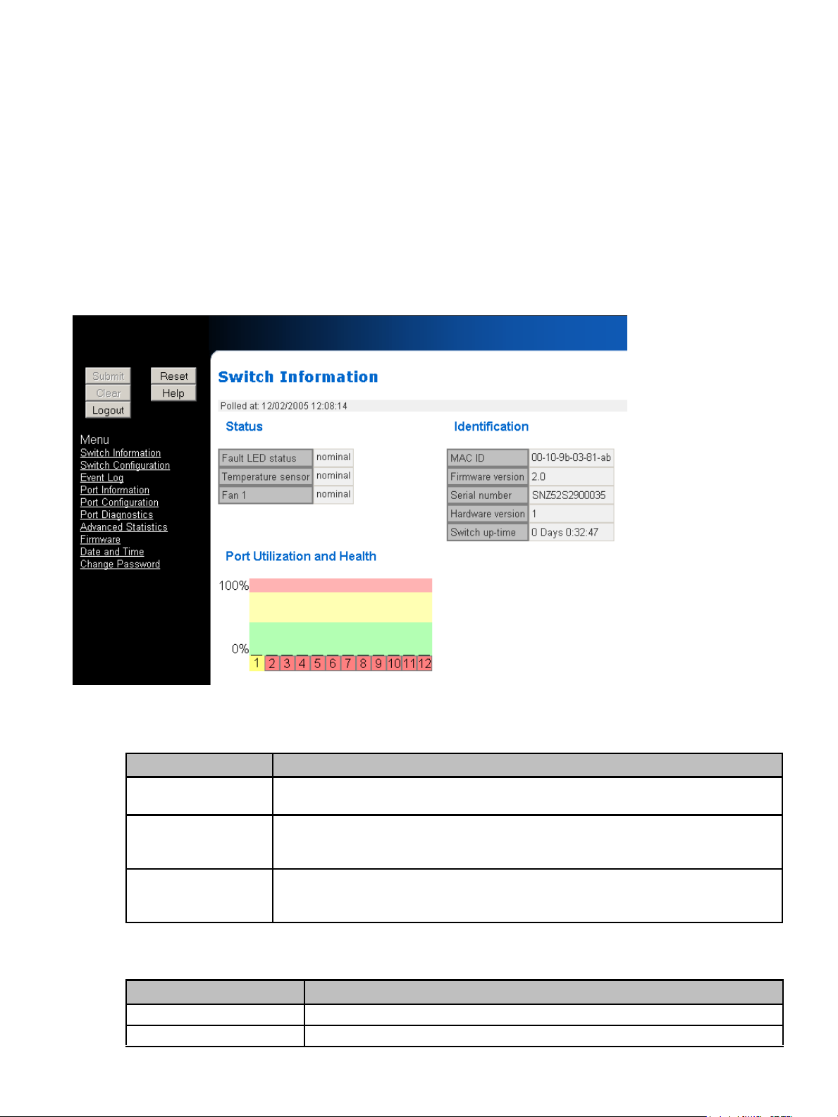
The Web Manager’s home page is the Switch Information page. This page is displayed first when the
Web Manager is opened and shows general switch information, including switch status, switch
identification information, and port health and utilization. The last time the switch was polled is
displayed at the top of the page.
This page continually refreshes to guarantee that the most current switch status is displayed. To
return to this page at any time, click the Switch Information menu item.
Figure 8 Switch Information page
Switch Status
Current status is provided for the following items.
Item Status Indicators
Fault LED status • nominal–the switch is operating normally.
Temperature sensor • nominal–the switch temperature is within the normal operating range.
Fan 1 • nominal–the fan unit is working properly.
Switch Identification
This section displays the following information.
Item Status Indicators
MAC ID A unique device address (MAC address) assigned to each switch at the factory.
Firmware version The current firmware loaded on the switch.
• faulted (red)–the Fault LED has been triggered.
• overtemp (red)–the enclosure temperature has exceeded the recommended operating range.
• faulted (red)–the fan unit has stopped operating. Verify that the power supply/fan
module is properly seated in the switch.
30-10022-01 loop switch user guide 19
Page 20

Item Status Indicators
Serial Number A unique identification number assigned to each switch at the factory.
Hardware version The hardware version of the switch.
Switch up-time The duration of time that the switch has been o perational. If the switch is rebo oted
Port Utilization and Health
This part of the Web page displays each port number, the port’s cu rrent health status, and a vertica l
bar indicating the port utilization.
Port utilization measures the amount of traffic passing through a port over a period of time. The port
utilization indicated by the vertical bar reflects the average of the sum of the transmit (Tx) and receive
(Rx) utilization for that port.
A port number is displayed in one of four colors depending on the port’s current health:
Port Color Indication
Green An SFP is inserted into the port and a device is connected to the SFP.
Yellow May indicate one of the following conditions:
• The port is bypassed. An SFP may be inserted in the port but there may not be a device
connected to the SFP.
• The port is in loopback mode. There is no device connected to the port. The transmit and
receiver are connected together on the SFP transceiver.
• The switch is receiving an F8 Failure notification, so the port is bypassed to allow remaining
devices to proceed with initialization.
• The port is a failover link in a cascade and is not currently active.
Red May indicate one of the following conditions:
• An SFP transmitter fault has been detected.
• Ordered sets are being transmitted, so traffic cannot be passed through the port.
• A data timeout fault has been detected.
• A loss of received signal amplitude from the device has been detected.
• A loss of word synchronization for a specified time has been detected, which may be caused
by poor signal strength, intermittent line conditions, and so on.
Gray May indicate one of the following conditions:
• The port status cannot be determined.
• There is no SFP connector inserted in the port.
or power is cycled, this value is reset.
Port utilization is measured by a vertical bar that moves upwards as utilization increases. The vertical
bar has the three distinct levels of utilization:
Bar Color Indication
Green The port is operating at optimal utilization.
Yellow The port is experiencing periods of heavy traffic.
Red The port has too much traffic on it and is not operating at desired levels. Some devices should
20 Switch Management
be transferred to other ports to improve port utilization.
Page 21

Configuring Switch Settings
Several switch configuration settings may be changed to customize the switch to the network
environment. The Switch Configuration page displays general switch settin gs, switch identifica tion
information, configuration file information, and the SCSI Enclosure Services (SES) AL_PA setting.
To make a change to the current switch configuration, you must know the switch password (the switch
prompts for the password before accepting changes to any configuration settings).
To view the Switch Configuration page, click Switch Configuration.
Figure 9 Switch Configuration page
Viewing and Modifying Switch Information
This section includes general switch identification information.
Setting Description
Name The name of the switch.
Location The location of the switch.
Contact Name The person or group to contact about the switch.
To change the name, location, or contact name:
1. Click Switch Configuration.
2. Enter the new value in the ap propria te text box.
3. Click Submit.
The Switch Configuration page displays the updated information.
Viewing and Modifying Network Configuration Settings
The switch’s network configuration displays the Dynamic Host Configuration Protocol (DHCP),
Ethernet IP address, Ethernet netmask, and default gateway settings. There are two sets of network
30-10022-01 loop switch user guide 21
Page 22

configuration settings. The “current” settings display the settings that the switch is using. T he
“Settings after Next Reset” are the network settings that are configured for the next switch reset.
Setting Description
DHCP For DHCP-enabled environments, you can enable the switch to acquire an IP
address from a DHCP server automatically. This feature is disabled by default.
Ethernet IP address The IP address for the switch.
Ethernet netmask The IP netmask address for the switch.
Default gateway The gateway address for the switch.
To change the switch’s network location settings:
1. Click Switch Configuration.
2. Enter the new value in the ap propria te “Settings after Next Reset” text box.
3. Click Submit.
The Switch Configuration page displays the updated information.
Enabling DHCP
When DHCP is enabled, the switch will automatically obtain an IP address from the DHCP server.
You will need to know this IP address in o rder to access the switch throug h the Web Manager. You
can locate the new IP address by attaching a serial cable and then using a serial terminal emulation
program to communicate with the switch through the Command Line Interface (CLI), or by contacting
your network administrator.
To enable DHCP:
1. Select the Enabled check b ox.
2. Click Submit.
Disabling DHCP
To disable DHCP:
1. Clear the Enabled check box.
2. Enter the switch’s network location information.
3. Click Submit.
Loading and Saving Switch Configuration Files
Switch configuration settings can be saved for backup purposes or for loading the same configuration
on multiple switches.
To save the current configuration:
1. Ensure that you are logged into th e switch (see “Submittin g Changes” on page 15).
2. Click Switch Configuration.
3. Under Configuration File, click Save current config uration to host.
4. When prompted by the File Downloa d box, click Sa ve to save the file to the computer.
5. In the Save As box, enter the location where you want to save th e file and click Save.
To load a saved configuration:
1. Ensure that you are logged into th e switch (see “Submittin g Changes” on page 15).
2. Under Configuration File, enter the location for the .cfg file in the text box, or use the Browse
button to navigate to the appropriate file.
3. In the Choose File dialog box, se lect the app ropria te file and click OK.
4. Click Load configuration to switch.
A message box is displayed confirming the download and required switch reset.
5. Click OK to proceed.
The switch loads the configuration file and automatically resets.
22 Switch Management
Page 23

Restoring the Factory Default Settings
If necessary, the switch settings can be reset to th eir factory de fault values; however, the network
configuration settings are retained.
To restore the factory default configuration:
1. Under Configuration File, click Rese t to Defau lt Setting s.
A message box is displayed confirming the request.
2. Click OK to restore the factory default configuration a nd reset the switch.
Setting the SES AL_PA
To facilitate communications through a SCSI Enclosure Services (SES) device, a SES AL_PA must
be defined for the switch. This section displays the current SES AL_PA setting and allows you to
enter a different AL_PA under the “AL_PA to request” field. The default setting is “04”.
To set the AL_PA for the SES device:
1. Click Switch Configuration.
2. Enter the new value in the “AL_PA to request” text box.
3. Click Submit.
The Switch Configuration page displays the updated information.
To disable the SES AL_PA setting:
1. Click Switch Configuration.
2. Enter “00” in the “AL_PA to request” text box.
3. Click Submit.
The Switch Configuration page displays the updated information.
To have the switch automatically assign an AL_PA for the SES device:
1. Click Switch Configuration.
2. Enter “FF” in the “AL_PA to request” text box.
3. Click Submit.
The Switch Configuration page displays the updated information.
Viewing the Event Log
The Event Log contains a list of up to 3000 event log messages generated by the switch. The Switch
Event Log page displays the event log messages with each message containing the following
information:
• Event Number – the number assigned to that specific event in the log.
• Event Date and Time – the date and time when the event was recorded in the log.
• Event Severity – the severity level for that event.
• Event Description – a brief description of the event.
For a complete list of event messages and severity levels, see : Event Messages on page 45.
To view the event log, click Event Log.
30-10022-01 loop switch user guide 23
Page 24

The Event Log page is displayed.
Figure 10 Event Log page
The last time the event log was polled is displayed at the top of the page.
Setting the Fault LED Threshold
The Fault LED threshold sets the minimum severity level at which an event message will trigger the
Fault LED to light. The default value is “critical”.
To change the Fault LED threshold:
1. Next to Fault LED Threshold, click the drop-down box to display a list of valid seve rity levels.
2. Select the new value in the d rop-down b ox.
3. Click Submit.
The new value is now set.
Setting the Log Threshold
The Log threshold sets the minimum severity level at which an event message will be recorded in the
event log. The default value is “warning”.
To change the Log threshold:
1. Next to Log Threshold, click the drop-down bo x to display a list of valid se verity levels.
2. Select the new value in the d rop-down b ox.
3. Click Submit.
The new value is now set.
Clearing the Event Log
To delete the current list of event log messages on the switch:
1. Click Clear Event Log.
A message box is displayed confirming the request.
24 Switch Management
Page 25

2. Click OK to delete the event log.
The event log is cleared out and a new event message is displayed reporting that the e vent
log has been cleared.
Clearing the Fault LED
To clear the Fault LED after an event message has triggered it:
1. Click Clear Fault LED.
A message box is displayed confirming the request.
2. Click OK to clear the Fault LED.
The switch’s Fault LED should turn off.
Saving the Event Log
To export the event log to the host system:
1. Click Save event log file to host.
The event log is displayed in the host system’s default text editor.
2. You can then select the appropriate directory to save the event log messages, change the
name of the file (if desired), and save the event log.
Configuring the Syslog Server
The switch can communicate with a syslog server that monitors switch events.
To configure the syslog server:
1. In the IP Address text box, enter the IP address for the syslog server.
2. From the Threshold drop-down me nu, select the minimu m severity level at which an even t
message will be sent to the syslog server.
Any messages that are equal to or higher in severity than the specified severity level are sent
to the syslog server. For example, if the severity level for syslog reporting is designated as
“alert,” then the switch logs messages of the “alert” or the “emergency” severity level
only—“emergency” is the only severity level higher than “alert”. The default setting is “critical”.
3. From the Facility drop-down me nu, select the repo rting gro up to se nd to the syslog ser ver.
The default setting is 1 (“userLevelMessages”).
30-10022-01 loop switch user guide 25
Page 26

The standard reporting groups are:
Reporting Group
• 0 – kernel messages
• 1 – user-level messages
• 2 – mail system
• 3 – system daemons
• 4 – security/authorization messages
• 5 – messages generated internally by syslogd
• 6 – line printer subsystem
• 7 – network news subsystem
• 8 – UUCP subsystem
• 9 – clock daemon
• 10 – security/authorization messages
• 11 – FTP daemon
• 12 – NTP subsystem
• 13 – log audit
• 14 – log alert
• 15 – clock daemon
• 16 – local use 0
• 17 – local use 1
• 18 – local use 2
• 19 – local use 3
• 20 – local use 4
• 21 – local use 5
• 22 – local use 6
• 23 – local use 7
4. In the Program text box, enter the nam e (32 printable characters maximu m) under wh ich to
log reports on the syslog server. The default value is “HP”.
5. Click Submit.
Enabling Syslog Server Reporting
To turn on syslog server reporting:
1. Select the Enabled check b ox.
2. Click Submit.
Disabling Syslog Server Reporting
To turn off syslog server reporting:
1. Clear the Enabled check box.
2. Click Submit.
26 Switch Management
Page 27

Viewing Port Information
The Port Information page displays the ports, their current health, the AL_PAs currently assigned to
each port, and the utilization for each port.
Port utilization measures the amount of traffic passing through a port over a period of time. For
example, if an initiator is transmitting data to a target, the initiator port displays a transmit (Tx) port
utilization value (%) while the target port displays a receive (Rx) port utilization value. If the same
initiator is receiving data from the target, the target port displays an Rx port utilization value (%) while
the initiator port displays a Tx port utilization value.
The Port Information page displays each port’s Rx and Tx utilization percentage based on low,
average, and high utilization.
Value Description
Low The lowest percentage of data communication through a port in the last 10 seconds.
Average The average percentage of data communication through a port in the last 10 seconds.
High The highest percentage of data communication through a port in the last 10 seconds.
To view port information, click Port Information.
The Port Information page is displayed.
Figure 11 Port Information page
30-10022-01 loop switch user guide 27
Page 28

Configuring Port Settings
The Port Configuration page displays the ports, their current health status, their current operating
speed, and SFP serial identification information.
To view the Port Configuration page, click Port Configuration.
Figure 12 Port Configuration page
Field Description
Port Displays the current health of the port. See “Port Utilization and Health” on page 20 for
additional information on port health.
Enabled Indicates if the port is enabled. The default setting is “Yes”.
Speed Indicates the current speed at which the specified port is running. The default port
speed is set to “2 Gb/s”.
SFP Serial ID (SID) When clicked, provides SFP information if an SFP is inserted in the port.
Enabling and Disabling Ports
Each port may be enabled or disabled. In normal operation, ports should be enabled to allow
attached devices to communicate through the switch. However, if a bad device is attached to a port,
the port may be disabled so that the device does not interfere with normal switch operation. The
default setting for all ports is “enabled”.
To enable or disable a port:
1. Click Port Configuration.
2. Select the specific port’s setting from the drop-down men u.
Setting Description
Yes The port is enabled.
No The port is disabled.
3. Click Submit.
Port Speed
Each port on the switch is capable of running at 2 or 1 Gb/s. Configuring a port to the “Auto” speed
setting enables the switch to detect the appropriate speed for the device attached to that port. The
default port speed setting is “2 Gb/s”.
To change a port’s speed:
28 Switch Management
Page 29

1. Click Port Configuration.
2. Select the specific port’s desired speed from the drop-d own menu.
Setting Description
1 Gb/s Set port speed to 1.0625 Gb/s.
2 Gb/s Set port speed to 2.125 Gb/s.
4 Gb/s Set port speed to 4.25 Gb/s (not supported)
Auto Automatically detect and set port speed.
3. Click Submit.
Viewing Port Diagnostics
This page displays diagnostic information pertaining to each port in the switch, including the port’s
current speed, how many times a device has been inserted into the port, and the curre nt port state.
This page also allows you to beacon or reset a port for troubleshooting purposes.
To view the current diagnostic settings, click Port Diagnostics.
The Port Diagnostics page is displayed.
Figure 13 Port Diagnostics page
Title Description
Port Colors indicate the current status of the port.
See “Port Utilization and Health” on page 20 for descriptions of the health indicators.
Speed Displays the actual speed at which the port is running. If a device is not connected to
the port, Link” is displayed.
Insertion Count Displays the number of times the port has been inserted into the network since the
switch was reset or the counters were cleared.
State Displays the current state of the port – either inserted or bypassed.
Beacon Forces the port LED to flash on and off continuously. Use this to locate and take action
on a specific port. The flashing overrides normal port indication until beaconing is
turned off; however, the port continues to operate normally.
30-10022-01 loop switch user guide 29
Page 30

Title Description
Force Reset A single-instance operation that places a port in bypass mode and then immediately
Clearing Insertion Counters
To clear the counters:
1. Click Clear Insertion Counters.
A message box is displayed confirming the request.
2. Click OK to clear the insertion counters.
Saving Diagnostic Information
To save diagnostic information to the host system:
1. Click Save diagnostic file to host.
The diagnostic information is displayed in the host system’s default text editor.
2. You can then select the appropriate directory to save the information, change the name of the
file (if desired), and save the diagnostic information.
Beaconing a Port
A port’s LED can be forced to flash on and off continuously for identifying a specific port or
troubleshooting purposes. The flashing overrides normal port in dication until beaco ning is turned off;
however, the port will continue to operate normally.
sets the port to auto-detect to re-insert the port. This feature may be used to diagnose
device problems when a device is locked up or experiencing a high number of failures
on a port.
To beacon a port:
1. Click Port Diagnostics.
2. Select the Beacon check box for the appropriate port.
3. Click Submit.
To stop beaconing a port:
1. Click Port Diagnostics.
2. Clear the Beacon check box for the ap propria te port.
3. Click Submit.
Resetting a Port
If necessary, a port can be placed into a forced reset. If the port is manually reset, the port is
temporarily placed in bypassed mode and then reset to re-insert the port. This feature may be used to
diagnose device problems when a device is locked up or experiencing a high number of failures on a
port.
To reset a port:
1. Click Port Diagnostics.
2. Select the Force Reset check bo x for the a ppropriate p ort.
3. Click Submit.
The selected port LED should start flashing.
The selected port LED should stop flashing.
30 Switch Management
Page 31

Viewing Advanced Statistics
This page displays information that may be used for the advanced troubleshooting of switch-related
issues.
To view the advanced statistics, click Advanced Statistics.
The Advanced Statistics page appears.
Figure 14 Advanced Statistics page
The Advanced Statistics page displays the following information:
Diagnostic Description
Low-level Link Low-level FC-1 traffic information.
High-level Link High-level FC-1 traffic information.
Frame Counts Frame count (FC-2 level traffic) information.
Class 2 Traffic Class-2 Fibre Channel data as defined by the current Fibre Channel specification.
Class 3 Traffic Class-3 Fibre Channel data as defined by the current Fibre Channel specification.
Class F Traffic Class-F Fibre Channel data as defined by the current Fibre Channel specification.
All Traffic All defined classes of Fibre Channel traffic.
To clear the statistics on any page:
1. Click the Clear Statistic Data check box.
2. Click Submit.
A message box is displayed confirming the request.
3. Click OK to clear the statistic data.
30-10022-01 loop switch user guide 31
Page 32

The Low-level link statistic page displays the following information:
Figure 15 Advanced Statistics Low-level Link page
Diagnostic Description
Sync Loss The number of times loss of word synchronization has occurred on the port for a
specified time. Synchronization loss occurs when the port stops receiving a signal for a
period of time.
Possible causes include:
• Poor connections or signal strength
• Rogue devices
• Intermittent hardware failures or line conditions.
Invalid OS The number of invalid ordered sets that have been detected. Ordered Set (OS) or word
errors can occur in bursts, which can potentially cause system performance issues.
Possible causes include:
• Poor connections or signal strength
• Rogue devices
• Intermittent hardware failures.
Link Failure The number of times the link on a port has failed.
Link-Reset Tx The number of Link-Reset ordered sets transmitted on the port. A port enters the
Link-Reset transmit state to begin the link reset procedure. This is caused by a link
timeout or a connection error.
Link-Reset Rx The number of Link-Reset ordered sets received on the port. The Link-Reset is
performed upon receiving a Link-Reset. When a port is receiving Link-Resets, it will
begin transmitting idles.
OLS Tx The number of Offline-State ordered sets (OLS) transmitted on the port. A port enters
the Offline-State to perform initialization after a port has been powered on or internally
reset. A port also enters Offline-State prior to powering off or performing internal
diagnostics. OLSs are normal; however, high counts could indicate problems.
OLS Rx The number of Offline-State ordered sets (OLS) received on the port. A port enters the
Offline-State when it receives the OLS primitive sequence. While in this state, the port
transmits the Link Reset (LR) primitive ordered set initiating a Link Reset. OLSs are
normal; however, high counts could indicate problems.
32 Switch Management
Page 33
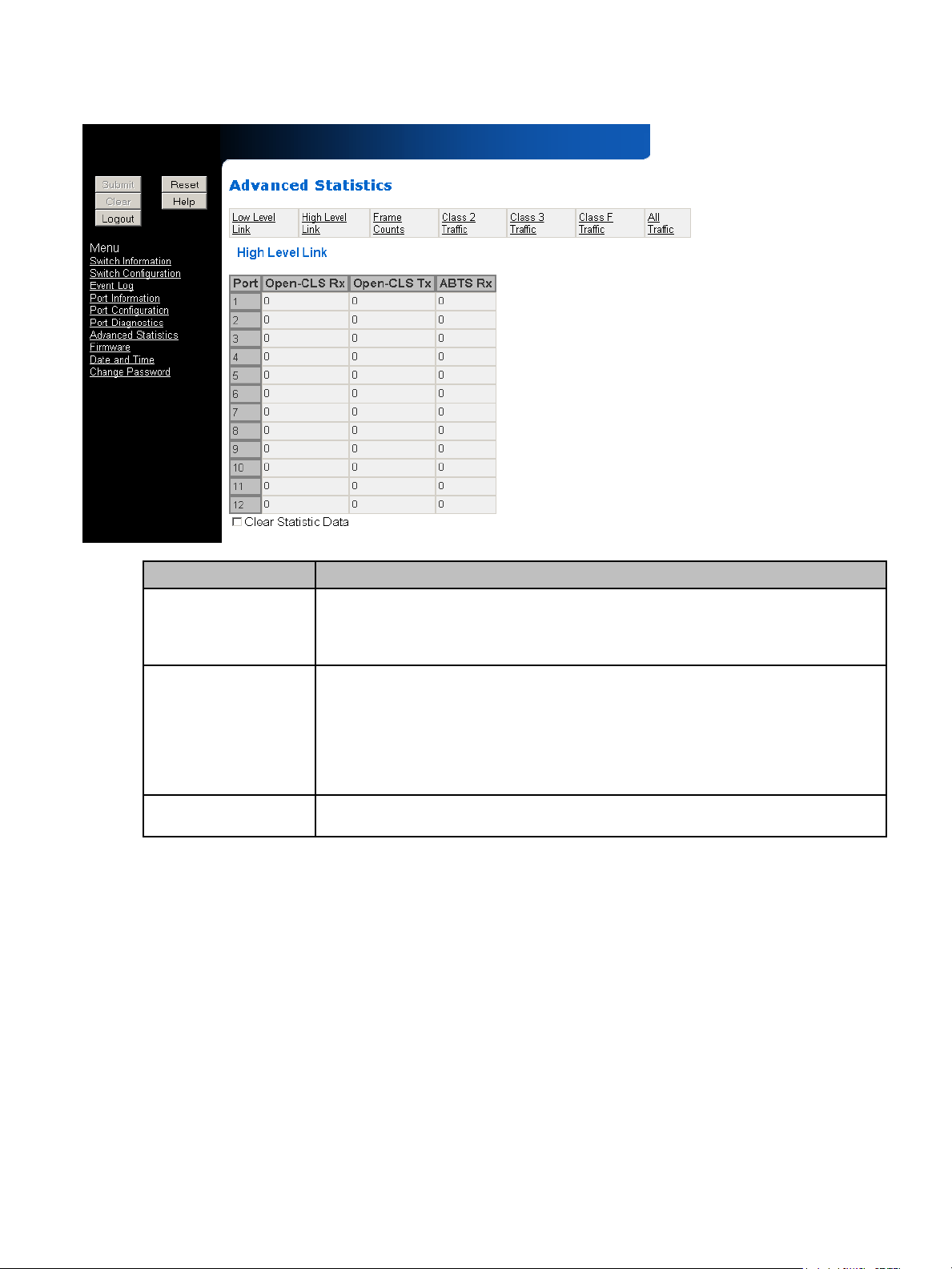
The High-level link statistic page displays the following information:
Figure 16 Advanced Statistics High-level Link page
Diagnostic Description
Open-CLS Rx The counter for the number of CLS received to OPNs sent. This occurs when the
target device refuses to accept an OPN. If the counter increases, attempts to send
data out the port will be affected and perform an ce will begin to d egrade. This ca n be a
sign of congestion or a slow device.
Open-CLS Tx The counter for the number of CLS transmitted to OPNs received. This occurs when
the port does not allow a remote device to send data to it, indicating the RX buffers are
full or the device is unavailable. Frames in the buffers are being held due to a
destination device not servicing frames. Frames then back up the TX queue for the
destination device until the switch does not allow the source device to send more
frames. This can be a sign of congestion on the destination port. A slow servicing
device may need tuning of the data I/O request size.
ABTS Rx The number of ABORT sequences received on the port. ABTSs are responses to the
error condition when a frame or sequence of frames are lost or out of order.
30-10022-01 loop switch user guide 33
Page 34

The Frame Counts statistic page displays the following information:
Figure 17 Advanced Statistics Frame Counts page
Diagnostic Description
CRC Errors The number of Cyclic Redundancy Check (CRC) errors that are detected in frames
passing through the port since the last switch reset or since the counters were cleared.
CRC errors can be caused by the following conditions:
• Connection problems with a remote device
• Link data corruption caused by a high number of Invalid TX words
• Bad cabling or other electromagnetic interference
• Partial SFP insertion
Short Frames The number of frames that are shorter than the minimum allowed frame size.
Long Frames The number of frames that have exceeded the maximum allowed frame size.
Invalid Words The number of invalid 10-bit words received on the port. This is typically caused by a
link corruption such as a code violation (10b/8b decoding), framing error, or a disparity
error.
Missing SOF/EOF The number of frames that are missing their Start-of-Frame (SOF) and/or
End-of-Frame (EOF) ordered sets.
The Class 2 Traffic, Class 3 Traffic, Class F Traffic, and All Traffic statistic pages display the following
information:
34 Switch Management
Page 35

Figure 18 Advanced Statistics Class 2 Traffic page
Diagnostic Description
Frames Rx The number of frames received for a particular class. For the All Traffic statistic page,
this is the total number of frames received from all classes.
Frames Tx The number of frames transmitted for a particular class. For the All Traffic statistic
page, this is the total number of frames transmitted from all classes.
K-octets Rx The number of Kilo-octets received for a particular class. For the All Traffic statistic
page, this is the total number of Kilo-octets received for all classes.
K-octets Tx The number of Kilo-octets transmitted for a particular class. For the All Traffic statistic
page, this is the total number of Kilo-octets transmitted for all classes.
30-10022-01 loop switch user guide 35
Page 36

Managing Firmware
The Firmware page displays the current and alternate firmware versions, enables users to select
which firmware version to run the next time the switch is reset, and provides a means to load new
firmware on the switch.
To check for new firmware on the Emulex Web site, click Help.
To view the firmware, click Firmware.
The Firmware page is displayed.
Figure 19 Firmware page
Loading New Firmware
To load new firmware on the switch:
1. Under Management, click the Load new firmware to switch link.
2. Log into the switch (see “Submitting Cha nges” on page 15).
3. Enter the directory path and the specific file name in the text box, or click Browse to navigate
to and select the appropriate file on the host system. The file should have a .dwn extension.
4. Click Program the File to load the new firm ware image.
Once the firmware has been installed, the new firmware should appear as the Next Reset
firmware.
5. Under Management, ensure that the Sw ap Next Rese t Image option is selected . The “Next
Reset” firmware version currently displayed will be loaded on the next boot cycle.
6. Click Reset to reset the switch using the selected firmware.
NOTE: When loading new firmware on the switch, clear the Web browser’s cache and files to
ensure the removal of the older firmware information. In Internet Explorer, use the key combination
C
TRL+F5, or select Tools > Internet Options and click Delete Files.
To select the Next Reset firmware version for the next boot:
1. Under Management, sele ct the Swap Next Reset Imag e check box. Th e alternate firmwar e
version currently displayed under Next Reset will be loaded on the next boot cycle.
2. Click Submit.
3. Click Reset to reset the switch.
36 Switch Management
Page 37

Configuring Date and Time Settings
The Switch Date and Time page displays the switch’s current date and time. During the initial Web
Manager session, the date and time for the switch are set based on the host system’s current
settings.
To set the date and time settings:
1. Click Date and Time.
The Switch Date and Time page is displayed.
Figure 20 Switch Date and Time page
2. Enter the new date and time settings in the New Date and Time text box.
3. Click Submit.
The new date and time appear under Current Date and Time.
To synchronize the current date and time settings with the host system:
1. Click Host Time.
The date and time of the current host system appear in the New Date and Time text box.
2. Click Submit.
The new date and time appear next to Current Date and Time.
30-10022-01 loop switch user guide 37
Page 38

Changing the Password
The Change Password page enables you to change the password for modifying the switch’s
configuration. The same password is used to access both the Web Manager and the CLI.
Note: Until the default switch password is changed, any user with knowledge of the default password can
make changes to the switch’s configuration.
To change the password:
1. Click Change Password .
The Change Password page is displayed.
Figure 21 Change Password page
2. Enter the new password in the New Password text box.
NOTE: The password must be between 1 and 80 characters in length and is case sensitive.
3. Enter the new password again in the Con firm New Password text box.
4. Click Submit.
A message box is displayed confirming the change to the switch’s configuration and that you
are logged in as an administrator (“admin”).
5. Click OK.
The Enter Network Password box is displayed.
6. Ensure that “admin” is entered for the User Na me, and type the curr ent password in the
Password field.
7. Click OK to submit the change.
The page displays the submission update result, and should state that the password was
updated successfully.
NOTE: To view the current page without displaying the submission results, click the View page
without submission results link.
38 Switch Management
Page 39

4Technical Reference
Troubleshooting Device Connections
Problem Recommended Action
SFP installed in one or more
ports, but LED is not lit
SFP installed, but only yellow
LED is lit
SFP installed with green LED lit,
but devices are not
communicating
1. Verify that the power cord is firmly seated into switch and is connected to a
properly earthed receptacle (outlet).
2. Check the Power LED to ensure that the switch is turned on.
3. Verify that the SFP is firmly seated.
1. Make sure that the device is powered on and operating properly.
2. Unplug the fiber cable from the node and verify that an optical signal is
present on the cable receiver lead.
3. Verify that the fiber cable is fully seated at either end.
If optical power meter is available, verify the device is transmitting a
signal.
If there is no signal present, the device may require rebooting, device
drivers may need to be reinstalled, or the HBA or disk controller hardware
may require servicing.
If a signal is present on both the cable lead and the end node, the HBA or
disk controller may require service.
4. Ensure that the device and switch are operational and set to the same
speed.
The switch is receiving a valid signal from the device, but no upper level
protocols are active.
1. Verify that the proper HBA device drivers are loaded for the appropriate
operating system and that the host has been configured to recognize
attached disk devices.
2. Improper FC-AL initialization could result from a defective or inoperative
adapter card or device. Run adapter diagnostics with a loopback
connector to see if the adapter is working properly.
3. Unplug the fiber cable from the end node and verify that an optical signal
is present on the cable receiver lead. If no signal is present, the cable’s
receiver lead may be bad and the device may be streaming F8 Failure
notifications.
Troubleshooting Management Connections
Problem Recommended Action
Serial cable installed, but
connection does not appear on
terminal
Ethernet cable installed, but Web
Manager does not appear
1. Cycle power by reinstalling the power cord.
2. Check the terminal emulation program’s serial port parameters.
3. Replace the serial cable. Make sure it is a null modem cable.
4. Verify the COM port is not already in use.
1. Ensure that a crossover Ethernet cable is used (unless using an Ethernet
hub).
2. Make sure the IP address and subnet mask are available and correct.
This may require contacting your IT administrator.
3. If going across a router, ensure you have the gateway address entered.
4. Check the communication path between the switch and workstation as
follows:
At a command line prompt, type ping DNS or IP (where “DNS or IP” is the
switch’s DNS name or IP address) and press
If a “Reply from…” or “...is alive...” message
can communicate.
If a “Request timed out” message
out), the devices cannot communicate. Trace the cabling. If needed,
reconnect the devices.
ENTER.
is displayed, the devices
is displayed (or the command times
30-10022-01 loop switch user guide 39
Page 40

Port Bypass Conditions and Recovery
Operational Condition Recovery
Rx_los is asserted by an
SFP/GBIC
Tx_fault is asserted by an
SFP/GBIC
F8 Failure notification is received
by the port
Loss of Sync (>100ms) The port stays bypassed until a signal is re-established. At that time, the port
Firmware Initiated The port stays bypassed until the firmware sets the port control back to
The port stays bypassed until rx_los is de-asserted. At that time, the port
insertion will be automatically retried. The port continues to stay bypassed
until the port can pass the port insertion criteria.
The port stays bypassed until tx_fault is de-asserted. At that time, the port
insertion will be automatically retried. The port continues to stay bypassed
until the port can pass the port insertion criteria.
The switch automatically tries to re-insert the device, by sending F7
Initialization notifications to the device connected to the bypassed port. The
port continues to stay bypassed until the device returns F7 Initialization
notifications to the port and passes the port insertion criteria.
insertion will be automatically retried. The port continues to stay bypassed
until the port can pass the port insertion criteria.
automatic. At that time, the port insertion will be automatically retried. The
port continues to stay bypassed until the port can pass the port insertion
criteria.
40 Technical Reference
Page 41

A Specifications
Switch Specifications
Specification Value
Number of Ports 12
Operating Rate All ports operate independently at 1.0625 or 2.125 Gb/s
Port Media Type SFP optical or copper based
Enclosure 1U half-rack form-factor
Management Interface Fibre Channel, RS-232, or 10/100 Ethernet
EU Compliance EU directive 2002/95/EC
Configurability Management interface configurable
Power On Selftest (POST) Yes
Dimensions 8.5" x 1.73" x 14.50" (W x H x D)
AC Power Input 50 or 60 Hz / 100 – 250 VAC / 1.0 – 0.5 A
AC Power Connector IEC connector
Weight Approximately 7 lbs.
Operating Conditions
The switch must be operated in a clean, dry environment with unrestricted airflow. Air flows in through
the cosmetic end and out through the business end (sometimes called the transceiver end or
“back-of-box”).
To avoid overheating, maintain a minimum clearance of two inch es (50.8 mi llimeter s) on each end of
the switch (the cosmetic end and the business end). Allow an adequate amount of space on the top
and sides of the switch for proper air ventilation. Do not place the switch on heat-generating surfaces.
Operating conditions are listed below.
Requirement Value
Operating Temperature 0°C to 40°C normal operation (ambient air temperature)
Storage -40°C to 80°C non-condensing
Power 50 or 60 Hz / 100 – 250 VAC / 1.0 – 0.5 A
30-10022-01 loop switch user guide 41
Page 42

42 Specifications
Page 43

BCLI Quick Reference
Connecting to the CLI
The Command Line Interface (CLI) can be accessed through a network interface usin g a terminal
emulation program, such as telnet, or through the serial interface from a local computer using a utility
program, such as HyperTerminal. Refer to the HP EVA 4000/6000/8000 30-10022-01 loop switch CLI
reference guide for detailed descriptions of CLI commands and usage.
To connect through a network interface:
Use a network terminal emulation program. For example, if using the teln et comman d on a
Windows workstation, type telnet <IPaddress> at a command prompt, where <IPaddress> is
the switch’s IP address.
To connect through a serial interface:
1. Attach one end of the included null-modem cable to the co mputer’s RS-232 serial port, and
attach the other end to the switch’s RS-232 serial port.
2. Open a terminal session through a serial termin al emulation program (su ch as
HyperTerminal®) with the appropriate serial port (for example, COM1) and the following serial
port parameters:
• Bits per second: 115200
• Data bits: 8
•Parity: None
•Stop bits: 1
• Flow control: None
3. If using HyperTerminal, press E
4. If using the tip co mmand on a UNIX workstation, do the following:
a. View the /etc/remote file and create an alias similar to Hardware but with the serial
port parameters above (suggested name: Switch).
b. Use the tip command to establish a connection through the created alias, for
example tip switch.
NTER to receive a prompt.
Logging In and Out
The CLI does not require login if only viewing basic system information. However, for viewing detailed
system information or configuring any switch settings, you must log in to the switch.
To log in to the CLI, type the password at the prompt and press E
“password”.
To log out of the CLI, type lo and press E
Using the CLI
The CLI enables users to monitor and change system and port configurations, configure even t
reporting parameters, and install firmware. For additional information on the CLI, see the HP EVA
4000/6000/8000 30-10022-01 loop switch CLI reference guide .
To enter a command, type the command text or the numb er of the com mand.
To return to the previous menu, type .. and press E
To return directly to the Root menu, type root and press E
To cancel a prompt or input request, press E
To display help for specific command, type ? <command> and press E
To display the current menu, press E
NTER. The default password is
NTER, or exit the terminal session.
NTER.
NTER.
NTER.
NTER.
NTER.
30-10022-01 loop switch user guide 43
Page 44

Frequent Switch Configuration Tasks
A list of frequent switch configuration-related tasks is provided below. The list displays the task and
the corresponding CLI command.
To… Type…
View switch information show sysinfo
Change general switch configuration config sys
Change the IP Address config network ip
Change a port’s speed config port speed
View the event log show events
Upgrade the firmware fw
Change the port settings config port
Reset the switch reset
View diagnostics diag
View port statistics information show stat
Reset the switch to factory default settings config default
Change the password config password
CLI Commands
All of the CLI commands for the 30-10022-01 loop switch are shown below in a tree diagram. Usin g
the “help” command at the command line may provide additional information.
root -->
li
lo
1. config --> 1. sys --> 1. time
2. name
3. location
4. contact
5. events
2. sesalpa
3. default
4. port --> 1. beacon
2. enable
5. password
6. network 1. show
2. dhcp
3. ip
7. ..
8. ?
2. diag --> 1. galpa
2. prtctrs
3. show --> 1. events
2. speeds
3. prtctrs
4. prtutilization
4. fw --> 1. tftp
2. xmodem
5. reset
6. ?
3. clrctr
4. beacon
5. clrctr
6. sysinfo
7. galpa
8. sensors
3. revert
4. show
6. sev
7. fault
8. evclr
9. clrled
10. syslog
3. speed
4. lip
4. mask
5. gateway
6. reset
5. ..
6. ?
9. sid
10. stat
11. dump
12. ..
5. reset
6. ..
11. cfgdump
12. cfgload
13. ..
14. ?
5. ..
6. ?
7. ..
8. ?
13. ?
7. ?
44 CLI Quick Reference
Page 45
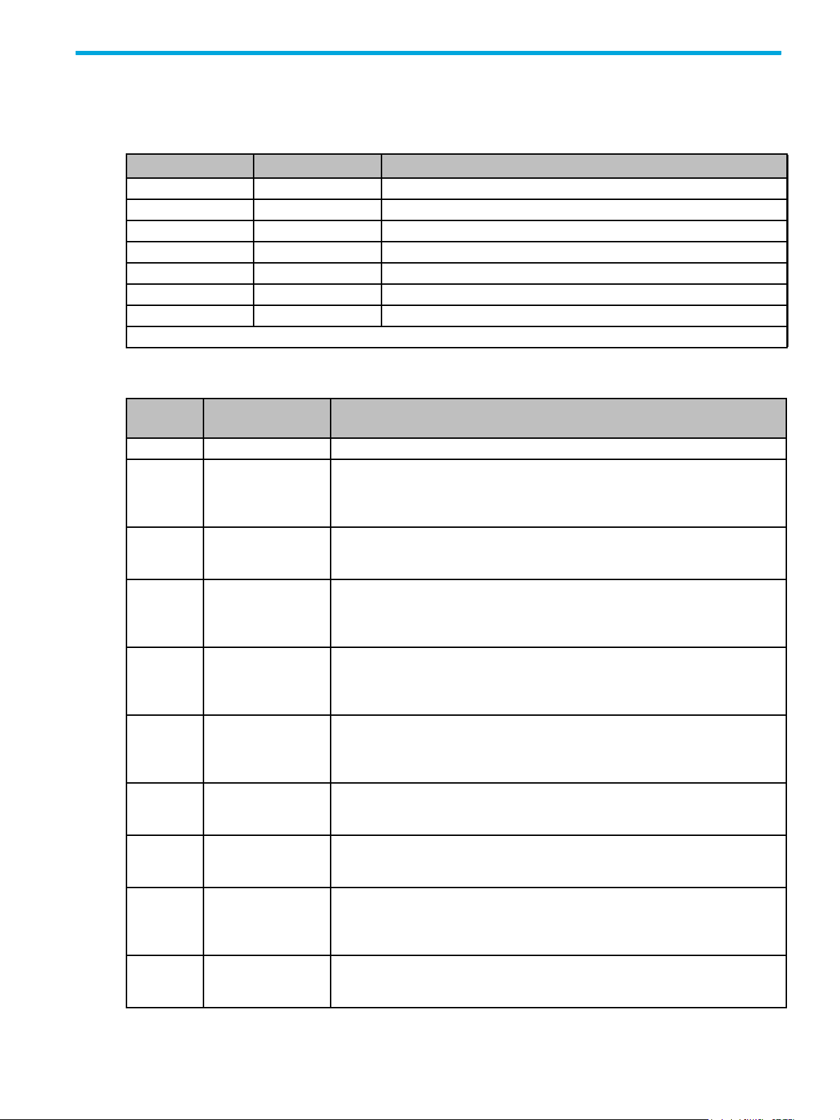
C Event Messages
The event messages for the 30-10022-01 switch are listed below. A message’s applicable severity
level, as defined below, is also provided.
Severity Level Severity Description
1 EMERGENCY Immediate action required; system failing.
2 ALERT Unrecoverable condition reported; major event in progress.
3 CRITICA L Event failed with possible loss of integrity.
4 ERROR Condition failed; action required.
5* WARNING Failed event occurred; no action required.
6 NOTIFY Configuration error or abnormal event occurred; no action required.
7 INFO Event occurred; no action required.
Note: * indicates default switch setting.
These severity levels can be used to designate the minimum severity level of events to be logged in
the Event Log and at which to illuminate the switch’s Fault LED.
Message
Number
1 NOTIFY Power-on self test passed.
2 ALERT An internal power-on self test failure has been detected. This indicates a
3 ALERT An internal power-on self test failure has been detected. This indicates a
4 ALERT A test failure has occurred in a fibre-channel port. If this is reported at
5 ALERT A test failure has occurred in a fibre-channel port. If this is reported at
6 ALERT A test failure has occurred on the internal SPI bus. This indicates a hardware
7 ALERT A test failure has occurred on the internal SPI bus. This indicates a hardware
8 ALERT A test failure has occurred on the internal SPI bus. This indicates a hardware
9 ALERT A test failure has occurred on the internal SPI bus. This indicates a hardware
10 ALERT A test failure has occurred on the internal SPI bus. This indicates a hardware
Severity Description
hardware problem in the unit. Contact technical support and report the
following information: the GPIO module <module name/number> is not
functioning.
hardware problem in the unit. Contact technical support and report the
following information: the serial port loopback failed on character <address>.
power-on, it indicates a hardware problem in the unit. Contact technical
support and report the following information: the failed port is <port number>
and it failed to compare.
power-on, it indicates a hardware problem in the unit. Contact technical
support and report the following information: the failed port is <port number>
and it timed out.
failure in the unit. Contact technical support and report the following
information: a loopback test failure has occurred on virtual port <port
number>.
failure in the unit. Contact technical support and report the following
information: SPI is not enabled on this chip.
failure in the unit. Contact technical support and report the following
information: a loopcheck test failure has occurred.
failure in the unit. Contact technical support and report the following
information: a sync error between chip <chip number> and <chip number>
has occurred.
failure in the unit. Contact technical support and report the following
information: a transmit failure on chip <chip number> has occurred.
30-10022-01 loop switch user guide 45
Page 46

Message
Number
11 ALERT A test failure has occurred on the internal SPI bus. This indicates a hardware
12 ALERT A test failure has occurred on the internal SPI bus. This indicates a hardware
13 ALERT The SPI test has not been run as SPI is not enabled.
14 ALERT An unknown diagnostics error has occurred. Contact technical support and
15 ALERT An internal error has occurred that will disrupt correct switch operation.
16 ALERT A memory test failure has occurred. This indicates a hardware problem in the
17 ERROR An internal error has occurred. Contact technical support and report the
18 EMERGENCY The temperature inside the box has reached a critical level. The unit will fail to
19 ALERT The temperature inside the box is above normal operating limits. The unit will
20 INFO The temperature in the unit has returned to normal operating levels.
23 EMERGENCY Fan 1 has stopped. It has either become jammed or been removed.
24 ALERT Fan 1 has started.
25 ALERT Power supply 1 is no longer providing power to the unit. Either AC power has
26 NOTIFY Power supply 1 is now delivering power to the unit.
33 NOTIFY The system time has been changed.
34 NOTIFY An internal error has occurred wh ile attempting to set t he system time. The
35 NOTIFY Loop UP on Port <port number>.
36 NOTIFY Loop DOWN on Port <port number>.
37 NOTIFY Port <port number> has logged too many CRC errors. It is being bypassed.
38 NOTIFY Port <port number> has logged too many ordered set errors. It is being
39 NOTIFY The speed for port <port number> has been set to <speed setting>.
41 NOTIFY Network hardware initialization was successful.
42 ERROR Network hardware initialization has failed.
43 ALERT An internal error has occurred. Contact technical support and report the
44 ERROR An internal error has occurred. Contact technical support and report the
45 ERROR The attempt to use DHCP to obtain an IP address has failed. This may
46 EMERGENCY System started.
Severity Description
failure in the unit. Contact technical support and report the following
information: a receive failure on chip <chip number> has occurred.
failure in the unit. Contact technical support and report the following
information: a router delivery failure on chip <chip number> has occurred.
report the following information: code <line numbers> chip <number> args
<arguments>.
Contact technical support and report the following information: switch chip
<chip number> is not communicating.
unit. Contact technical support and report the following information: the
address that was detected as failing is <address>.
following information: thread <thread number>: <thread number>.
continue operating if this situation is not resolved. Verify the fans are
operating and are not blocked.
continue to operate but this situation should be resolved. Verify the fans are
operating and are not blocked.
been removed or the power supply has failed.
time has not been changed.
bypassed.
following information: the Ethernet MAC address cannot be located in the
configuration area. Without this information the network hardware cannot be
initialized. Continuing without network support.
following information: the Ethernet hardware device could not be initialized.
Continuing without network support.
indicate there is no network connectivity or a DHCP server is not available on
the network. The unit will revert to the configured IP information instead.
46 Event Messages
Page 47

Message
Number
47 INFO The event severity filter has been changed to <value>.
48 INFO The event fault LED threshold has been changed to <value>.
49 INFO The event log has been cleared.
50 INFO The fault LED has been turned off.
51 INFO The configuration has been reset to defaults.
52 INFO The administration password has been changed.
53 ERROR A severe internal error has occurred. Conta ct technical sup port and report the
54 ERROR An internal error has occurred. Contact technical support and report the
56 ERROR An internal error has occurred. Contact technical support and report the
Severity Description
Note: This event is automatically displayed in the event log, regardless of the
current event log or Fault LED threshold setting.
Note: This event is automatically displayed in the event log, regardless of the
current event log or Fault LED threshold setting.
Note: This event is automatically displayed in the event log, regardless of the
current event log or Fault LED threshold setting.
following information: an unhandled exception has been caught.
following information: there has been an invalid return from menuLookup().
following information: an invalid speed value has been detected, defaulting to
'auto'.
30-10022-01 loop switch user guide 47
Page 48

48 Event Messages
Page 49

DAL_PA Cross References
Arbitrated Loop Physical Addresses
AL_PA AL_PA ID AL_PA AL_PA ID AL_PA AL_PA ID
(hex) (hex) (decimal) (hex) (hex) (decimal) (hex) (hex) (decimal)
EF 00 0 A3 2B 43 4D 56 86
E8 01 1 9F 2C 44 4C 57 87
E4 02 2 9E 2D 45 4B 58 88
E2 03 3 9D 2E 46 4A 59 89
E1 04 4 9B 2F 47 49 5A 90
E0 05 5 98 30 48 47 5B 91
DC 06 6 97 31 49 46 5C 92
DA 07 7 90 32 50 45 5D 93
D9 08 8 8F 33 51 43 5E 94
D6 09 9 88 34 52 3C 5F 95
D5 0A 10 84 35 53 3A 60 96
D4 0B 11 82 36 54 39 61 97
D3 0C 12 81 37 55 36 62 98
D2 0D 13 80 38 56 35 63 99
D1 0E 14 7C 39 57 34 64 100
CE 0F 15 7A 3A 58 33 65 101
CD 10 16 79 3B 59 32 66 102
CC 11 17 76 3C 60 31 67 103
CB 12 18 75 3D 61 2E 68 104
CA 13 19 74 3E 62 2D 69 105
C9 14 20 73 3F 63 2C 6A 106
C7 15 21 72 40 64 2B 6B 107
C6 16 22 71 41 65 2A 6C 108
C5 17 23 6E 42 66 29 6D 109
C3 18 24 6D 43 67 27 6E 110
BC 19 25 6C 44 68 26 6F 111
BA 1A 26 6B 45 69 25 70 112
B9 1B 27 6A 46 70 23 71 113
B6 1C 28 69 47 71 1F 72 114
B5 1D 29 67 48 72 1E 73 115
B4 1E 30 66 49 73 1D 74 116
B3 1F 31 65 4A 74 1B 75 117
B2 20 32 63 4B 75 18 76 118
B1 21 33 5C 4C 76 17 77 119
AE 22 34 5A 4D 77 10 78 120
AD 23 35 59 4E 78 0F 79 121
AC 24 36 56 4F 79 08 7A 122
AB 25 37 55 50 80 04 7B 123
AA 26 38 54 51 81 02 7C 124
A9 27 39 53 52 82 01 7D 125
A7 28 40 52 53 83 00 7E 126
A6 29 41 51 54 84 --- 7F 127
A5 2A 42 4E 55 85 --- --- ---
30-10022-01 loop switch user guide 49
Page 50

50 AL_PA Cross References
Page 51

Glossary
ABTS Abort Basic Link Service.
AL_PA or Arbitrated Loop
Physical Address
CLI Command Line Interface. A command-based interface for configuring, managing, and
CLS Close Primitive Signal. Sent by a port that is currently communicating on the loop, to close
CRC Cyclic Redundancy Check. Used to check the integrity of a data frame.
DHCP Dynamic Host Configuration Protocol
EOF End Of Frame. A group of ordered sets used to mark the end of a frame.
FC-AL Fibre Channel Arbitrated Loop
Fibre Channel Fibre Channel is a dat a transfer interface technology that map s several common transpo rt
Frame A data unit containing a start-of-frame (SOF) delimiter, header, payload, cyclic
A one-byte value used to identify a port in an Arbitrated Loop topology. The value of the
AL_PA corresponds to bits 7:0 of the 24-bit Native Address Identifier.
displaying switch settings.
communication to another port.
protocols including IP and SCSI, allowing it to merge high-speed I/O and networking
functionality in a single connectivity technology. Fibre channel is an open standard as
defined by ANSI and OSI standards and operates over copper and fiber optic cabling at
distances of up to 10 Kilometers. It is unique in its support of multiple interoperable
topologies including point-to-point, arbitrated-loop and switching and it offers several
qualities of service for network optimization. With its large packet sizes, Fibre Channel is
ideal for storage, video, graphic and mass data transfer applications.
redundancy check (CRC), and an end-of-frame (EOF) delimiter. The payload can be
0-2112 bytes, and the CRC is 4 bytes.
Gb/s Gigabits per second.
Gigabit 1,062,500,000 bits per second in Fibre Channel.
HBA Host Bus Adapter. An interface between a server or workstation bus and the Fibre
Channel network.
IP Internet Protocol. The addressing part of TCP/IP.
LED Light-Emitting Diode. A status indicator on a switch.
LIM Loop Initialization Master
LIP Loop Initialization Primitive. A means to get an AL_PA address, to indicate a loop failure,
or to reset a port.
LISA Loop Initialization for Soft-Assigned (remaining) AL_PAs
OPN Open Primitive Signal. This is sent by a device that has won the arbitration process to
open communication with one or more ports on the loop.
OS Ordered Set. A group of low-level protocols used to manage frame transport, initialization,
and media access, and to distinguish Fibre Channel control information from data.
POST Powered On Self Test. A routine that the switch performs to test its components.
RAS Reliability, Availability, and Serviceability
SBOD™ Switched Bunch of Disks enclosure. A configuration with a single drive per port for higher
reliability, accessibility, and serviceability.
SCSI Small Computer System Interface. Standard interface for storage modules.
30-10022-01 loop switch user guide 51
Page 52

SES SCSI Enclosure Services. A subset of the SCSI protocol used to monitor temperature,
power, and fan status for enclosed devices.
SFP Small Form-Factor Pluggable transceiver. These transceivers are fully compliant with
FC-PI and MSA standards and occupy less than half the bo ard sp ace of the existing GBIC
products.
SOC Switch On a Chip
SOF Start Of Frame. A group of ordered sets used to mark the beginning of a frame.
TFTP Trivial File Transfer Protocol
Transceiver A device that converts one form of signaling to another for both transmission and
reception. SFPs and GBICs are transceivers.
52
Page 53

Index
A
AL_PA Cross References 49
authorized reseller, HP
6
C
CLI
commands
connecting
frequent tasks
logging in and out
configuration files
configuring
network interface
switch settings
Web Manager
44
43
44
43
22, 36
13
21
14
D
date and time settings 37
desktop installation
diagnostics
port
29
displaying
event log
port diagnostics
port information
switch status
23
7
29
27
19
E
ethernet LEDs 8
event log
event log messages
23
45
F
features, switch 6
firmware
36
changing versions
36
G
glossary 51
H
help, obtaining 6
HP
authorized reseller
storage web site
Subscriber’s choice web site
6
6
I
installation, switch 7
guidelines
installing the switch
introduction
7
7
5
6
L
LEDs
ethernet
port
Power
switch
system
System Fault
Temp Fault
logging in and out
8
9
8
7
8
8
8
43
M
managing the switch 19
N
network interface configuration 13
network settings
21
O
operating conditions 41
overview
5
P
password 43
changing
port
diagnostics
information
port bypass
conditions and recovery
port LED
ports
speed
powering on the switch
38
29
27
40
9
28
11
R
rack installation 7
guidelines
7
S
serial interface connection 43
SFP
attaching devices
compatibility
installation
removal
shipped contents
speed, port
Subscriber’s choice, HP
switch
changing the password
configuration
9
28
10
9
9
7
6
38
21
30-10022-01 loop switch user guide 53
Page 54

configuration files 22, 36
date and time settings
event log
event log messages
features
firmware
identification
initial setup
installation
LEDs
management
network settings
operating conditions
overview
package contents
port diagnostics
port information
powering on
settings
specifications
status
unpacking
system LEDs
23
6
36
21
17
7
7
13, 19
21
5
7
29
27
11
21
41
19
7
8
T
temperature 41
terms
see glossary
time and date settings
troubleshooting
51
39
45
41
37
37
switch status
time settings
web sites
HP storage
HP Subscriber’s choice
19
37
6
6
U
UL guidelines 7
unpacking the switch
V
viewing
event log
port diagnostics
port information
switch status
23
29
27
19
W
Web Manager 13
configuration
configuration files
event log
firmware
getting started
initial switch setup
network location
network settings
overview
password
port diagnostics
port information
port speed
switch identification
14
23
36
13
21
21
14
38
29
27
28
7
22, 36
17
21
54
 Loading...