

Page 1

Troubleshooting Guide
HP t5740/t5745 Thin Clients and HP st5742/st5747
Streaming Thin Clients
Page 2

© Copyright 2009 Hewlett-Packard
Development Company, L.P. The
information contained herein is subject to
change without notice.
Microsoft and Windows are trademarks of
Microsoft Corporation in the U.S. and other
countries.
The only warranties for HP products and
services are set forth in the express
warranty statements accompanying such
products and services. Nothing herein
should be construed as constituting an
additional warranty. HP shall not be liable
for technical or editorial errors or omissions
contained herein.
This document contains proprietary
information that is protected by copyright.
No part of this document may be
photocopied, reproduced, or translated to
another language without the prior written
consent of Hewlett-Packard Company.
Troubleshooting Guide
HP t5740/t5745 Thin Clients and HP
st5742/st5747 Streaming Thin Clients
First Edition (November 2009)
Document Part Number: 599219-001
Page 3

About This Book
WARNING! Text set off in this manner indicates that failure to follow directions could result in bodily
harm or loss of life.
CAUTION: Text set off in this manner indicates that failure to follow directions could result in
damage to equipment or loss of information.
NOTE: Text set off in this manner provides important supplemental information.
iii
Page 4

iv About This Book
Page 5

Table of contents
1 Product Description ........................................................................................................................................ 1
Thin Client Management Solutions ...................................................................................................... 1
HP t5740/t5750 Thin Clients ................................................................................................ 1
HP st5742/st5747 Streaming Thin Clients ........................................................................... 2
Product features ................................................................................................................................... 2
Front Panel Components ..................................................................................................... 2
Top Components ................................................................................................................. 3
Rear Panel Components ..................................................................................................... 4
Installing the Antenna (Wireless Models) ............................................................................ 4
Installing the Rubber Feet .................................................................................................... 5
Installing the Stand .............................................................................................................. 5
Removing the Stand ............................................................................................................ 6
Serial Number Location ....................................................................................................... 6
2 Hardware Changes ......................................................................................................................................... 7
General Hardware Installation Sequence ............................................................................................. 7
Removing and Replacing the Secure USB Compartment Cover ......................................................... 8
Removing the Secure USB Compartment Cover ................................................................ 8
Replacing the Secure USB Compartment Cover ................................................................. 9
Removing and Replacing the Side Access Panel and Metal Side Cover ........................................... 10
Removing the Side Access Panel and Metal Side Cover .................................................. 10
Replacing the Metal Side Cover and Side Access Panel .................................................. 11
Installing Thin Client Options .............................................................................................................. 12
Installing the USB Device .................................................................................................. 13
Removing and Replacing the Battery ................................................................................ 13
Installing a Secondary Flash Memory Module ................................................................... 14
Installing a Second SO-DIMM ........................................................................................... 15
Installing the PCI Express Expansion Module and PCI Express Card .............................. 17
External Drives .................................................................................................................. 17
3 Mounting the Thin Client .............................................................................................................................. 18
HP Quick Release .............................................................................................................................. 18
Supported Mounting Options ............................................................................................. 20
Non-supported Mounting Option ........................................................................................ 22
v
Page 6

4 BIOS Settings, (F10) Utility .......................................................................................................................... 23
Using the BIOS Settings ..................................................................................................................... 23
Changing BIOS Settings from the repset utility ................................................................. 23
Changing BIOS Settings Using the F10 Utility ................................................................... 24
Setup Utility—System Information ..................................................................................... 25
Setup Utility—Standard CMOS Features .......................................................................... 25
Setup Utility—Advanced BIOS Features ........................................................................... 25
Setup Utility—Integrated Peripherals ................................................................................. 26
Setup Utility—Power Management Setup ......................................................................... 27
Setup Utility—Utility Task Actions ...................................................................................... 27
5 Diagnostics and Troubleshooting ............................................................................................................... 28
LEDs ................................................................................................................................................... 28
Power-On Sequence .......................................................................................................................... 29
Power-On Diagnostic Tests ................................................................................................................ 29
Beep Codes ........................................................................................................................................ 30
POST Error Messages ....................................................................................................................... 30
Troubleshooting .................................................................................................................................. 31
Basic Troubleshooting ....................................................................................................... 31
Diskless (No-Flash) Unit Troubleshooting ......................................................................... 32
6 Restoring the Flash Image ........................................................................................................................... 34
System Requirements ........................................................................................................................ 34
Getting Started ................................................................................................................................... 34
Formatting a USB Flash Drive ............................................................................................................ 35
Unpacking the Image and Tools for Deployment ............................................................................... 35
Deploying with PXE ............................................................................................................................ 35
Appendix A Specifications .............................................................................................................................. 36
Appendix B Adding an Image Restore Tool .................................................................................................. 38
Appendix C Configuring a PXE Server .......................................................................................................... 39
Prerequisites ...................................................................................................................................... 39
Installing Remote Installation Services (RIS PXE Server) ................................................................. 39
Authorizing Remote Installation Services (RIS PXE Server) .............................................................. 40
Configuring Remote Installation Services .......................................................................................... 40
Set User Permissions on the Active Directory Server ........................................................................ 40
RIS Menu ........................................................................................................................................... 41
Creating Network Bootable Disk to Map Drives ................................................................................. 41
For More Information .......................................................................................................................... 41
vi
Page 7

Appendix D System BIOS ............................................................................................................................... 42
Restoring a Corrupt BIOS .................................................................................................................. 42
Updating a BIOS ................................................................................................................................ 43
Index ................................................................................................................................................................... 44
vii
Page 8

viii
Page 9

1 Product Description
The thin client exhibits the following features:
●
no moving parts
●
no hard drives or diskette drives
●
5-minute setup time
●
central deployment and management using a broad range of easy and scalable remote
management solutions
Thin Client Management Solutions
Differing thin client models have differing solutions as indicated in the following sections.
HP t5740/t5750 Thin Clients
HP has a comprehensive suite of management solutions to fit your needs. This allows you to choose
solutions that will work best in your environment.
HP ThinState Tools are a set of handy utilities that allow you to copy settings and software images
from one thin client to another using a USB drive key. HP ThinState tools complement other
management solutions and are included with HP thin client operating systems.
HP Device Manager is an enterprise-class thin client management software application that allows
customers to view their thin client assets remotely and to manipulate those thin clients to meet the
required business need. It is robust, yet easy to install and use. HP Device Manager lets you track,
configure, upgrade, clone, and manage thousands of individual devices from a centralized location.
HP Device Manager agents are included in most HP thin clients.
HP Client Automation is an industry-leading device management product, which is part of a bigger
Business Service Automation environment management solution. With HP Client Automation, you
can manage simple thin client deployments or highly complex IT environments that contain a
combination of thin clients, PCs, blades, servers and other common computer-based resources. HP
Client Automation agents work with all HP thin clients. For more information on HP Client Automation,
please visit the HP Web site at
http://www.hp.com and search for “Business Service Automation.”
HP continues to partner with Altiris to manage HP thin clients. Altiris Deployment Solution is a leading
tool for quick deployment and ongoing management of thin clients in your organization. For additional
information, refer to the Quick Setup and Getting Started Guide that came with your thin client, and
visit the Altiris Web site at
http://www.altiris.com/.
Thin Client Management Solutions 1
Page 10

HP st5742/st5747 Streaming Thin Clients
Since this Streaming Thin Client is flashless, it is specifically for use with streaming operating system
applications, such as HP Image Manager, HP TeachNow, and Citrix Provisioning Server. A local
operating system cannot be installed on this device, so it cannot execute Linux or Microsoft Windows
Embedded Standard 2009. Typically this type of client receives a preboot executable using Preboot
eXecution Environment (PXE), and then connects via Ethernet to a remote server which contains the
disk image for this client.
Product features
For more information, refer to the model-specific QuickSpecs at http://h18004.www1.hp.com/
products/quickspecs/QuickSpecs_Archives/QuickSpecs_Archives.html.
Front Panel Components
Figure 1-1 Front panel components
(1) Secure USB compartment (4) Line-out (headphone) audio connector
(2) Power button (5) Line-in (microphone) connector
(3) Flash activity LED (6) Universal serial bus (USB) connectors (2)
For more information, refer to the model-specific QuickSpecs at
http://h18004.www1.hp.com/products/quickspecs/
QuickSpecs_Archives/QuickSpecs_Archives.html.
2 Chapter 1 Product Description
Page 11
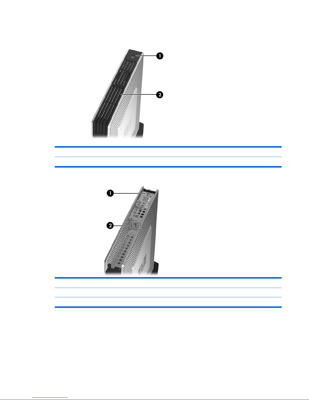
Top Components
Figure 1-2 Top components, external view
(1) Cable lock slot
(2) Secure USB compartment
Figure 1-3 Top components, internal view
(1) Cable lock slot
(2) Secure USB compartment ports (2)
(3) Microsoft diskless COA allowing streaming of a Microsoft Windows operating system (st5742 only)
The secure USB compartment allows you to use two USB devices in a secured location.
Product features 3
Page 12
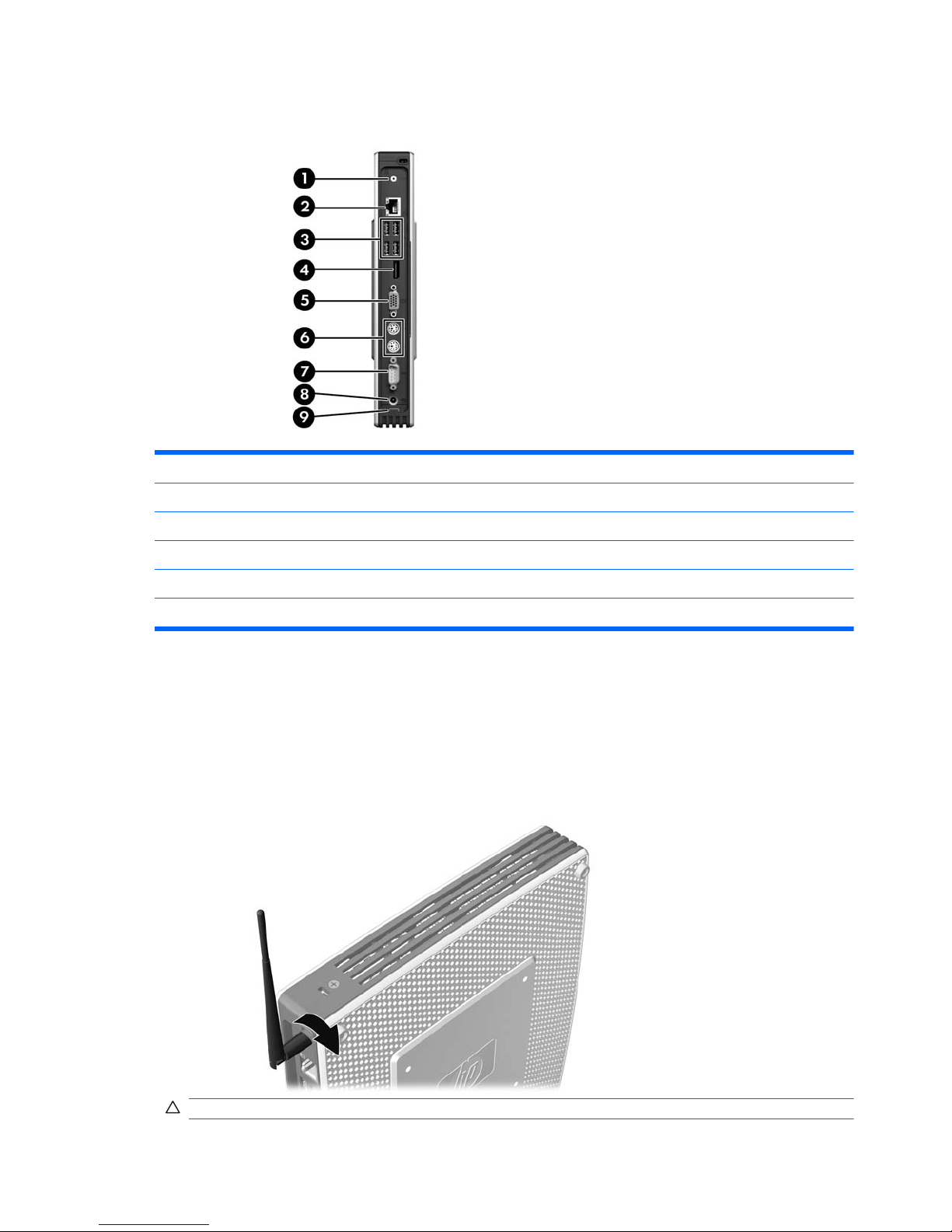
Rear Panel Components
Figure 1-4 Rear panel components
(1) Wireless antenna* (6) PS/2 connectors (2)
(2) Ethernet RJ-45 connector (7) Serial connector
(3) Universal serial bus (USB) connectors (4) (8) Power connector
(4) DisplayPort connector (9) Power cord retention slot
(5) VGA connector
*Available on some models. Refer to the model-specific QuickSpecs at www.hp.com for details.
The wireless antenna allows you to send and receive wireless signals to communicate with wireless
local area networks (WLAN).
Installing the Antenna (Wireless Models)
▲
Screw the antenna in place on the rear of the thin client.
Figure 1-5 Installing the antenna
CAUTION: To prevent damage to the antenna mounting, do not overtighten the antenna.
4 Chapter 1 Product Description
Page 13
Installing the Rubber Feet
To install the rubber feet:
1. Lay the thin client on its right side.
2. Remove the feet from their backing.
3. Press each foot down securely onto a corner of the left side of the thin client.
Figure 1-6 Installing the rubber feet
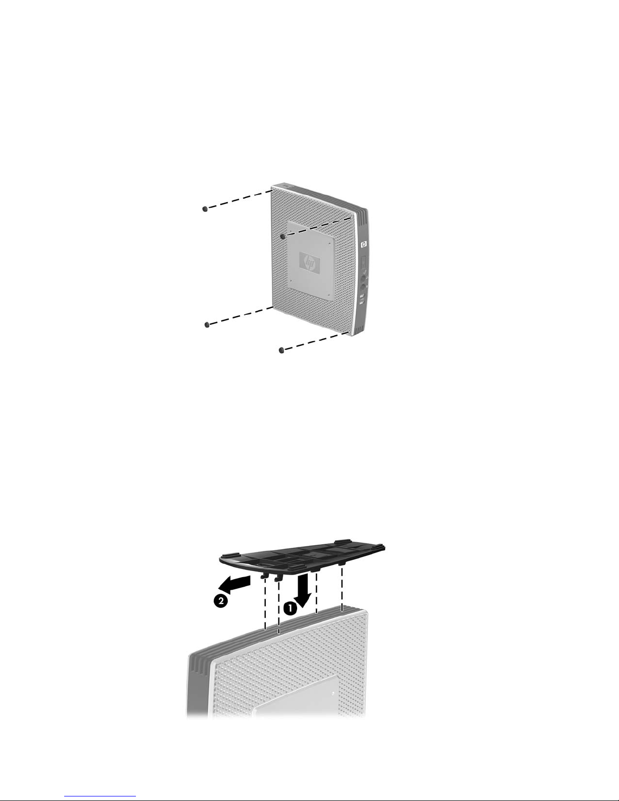
Installing the Stand
If the thin client will be installed in an vertical orientation and it will not be mounted, the stand should
be installed for stability.
To install the stand:
1. Turn unit upside down.
2. Locate the slots on the bottom of the unit into which the tabs on the stand fit.
3. Insert the tabs into the slots (1), and then slide the stand about 1.26 cm (1/2 inch) toward the
back of the unit until it locks into place (2).
Figure 1-7 Installing the stand
Product features 5
Page 14
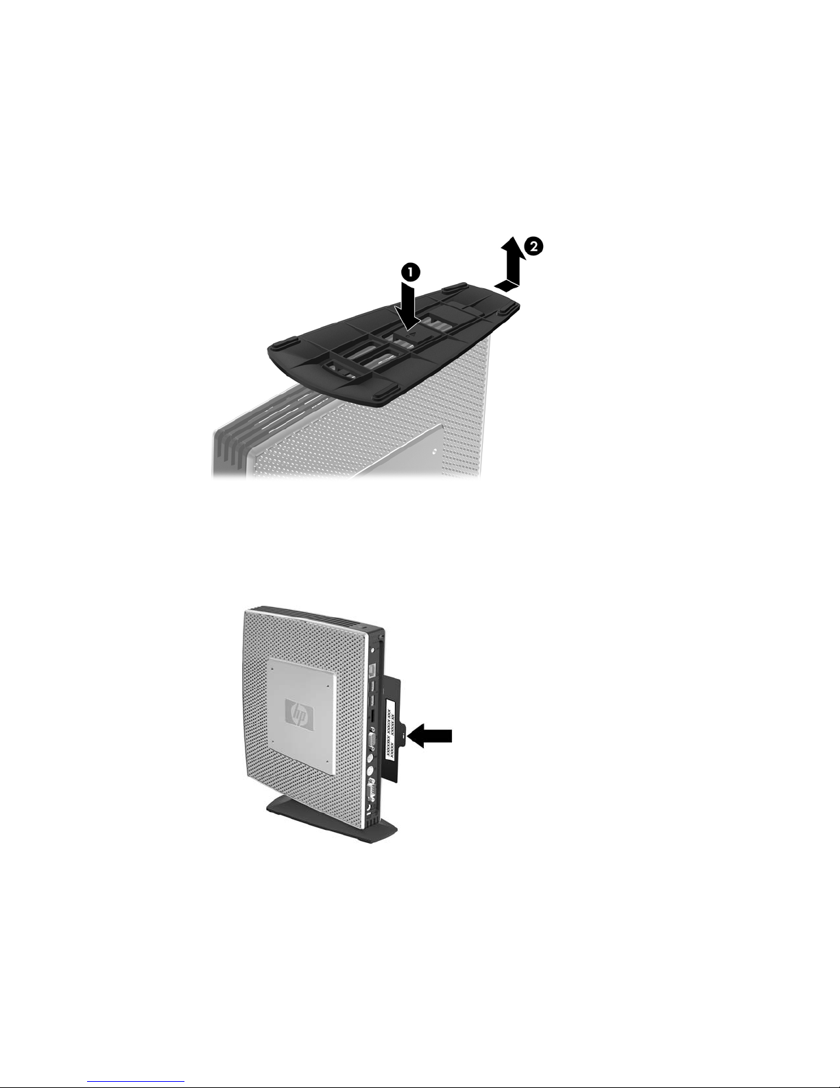
Removing the Stand
To remove the stand:
1. Turn unit upside down.
2. Press the tab (1), and then slide the stand about 1.26 cm (1/2 inch) toward the front of the unit
and lift the stand off the unit (2).
Figure 1-8 Removing the stand
Serial Number Location
Every thin client includes a unique serial number located as shown in the following illustration. Have
this number available when contacting HP customer service for assistance.
Figure 1-9 Serial number location
6 Chapter 1 Product Description
Page 15

2 Hardware Changes
General Hardware Installation Sequence
To ensure the proper installation thin client hardware components:
1. Back up any data, if necessary.
2. If the thin client is powered on:
a. Turn the unit and any other attached devices off.
b. Disconnect the power cord from the wall outlet.
c. Disconnect any external devices or cables, such as an antenna or cable lock.
WARNING! To reduce the risk of personal injury from electrical shock and/or hot surfaces, be
sure to disconnect the power cord from the wall outlet and allow the internal system components
to cool before touching.
WARNING! To reduce the risk of electrical shock, fire, or damage to the equipment, do not
plug telecommunications or telephone connectors into the network interface controller (NIC)
receptacles.
CAUTION: Static electricity can damage the electronic components of the thin client or
optional equipment. Before beginning these procedures, ensure that you are discharged of static
electricity by briefly touching a grounded metal object.
3. Remove the secure USB compartment cover. See Removing and Replacing the Secure USB
Compartment Cover on page 8 for more information.
4. Remove the stand, if it is installed. See
Removing the Stand on page 6 for more information.
5. Remove the side access panel and metal side cover. See
Removing and Replacing the Side
Access Panel and Metal Side Cover on page 10 for more information.
6. Remove any hardware that you will replace.
7. Install or replace equipment. For removal and replacement procedures, see the following
sections:
●
Installing the USB Device on page 13
●
Installing the PCI Express Expansion Module and PCI Express Card on page 17
●
Removing and Replacing the Battery on page 13
General Hardware Installation Sequence 7
Page 16

●
Installing a Secondary Flash Memory Module on page 14
●
Installing a Second SO-DIMM on page 15
NOTE: Option kits include more detailed installation instructions.
8. Replace the side access panel and metal side cover. See Removing and Replacing the Side
Access Panel and Metal Side Cover on page 10 for more information.
9. Install the stand, if you will be using the thin client unmounted in a vertical orientation. See
Installing the Stand on page 5 for more information.
10. Replace the secure USB compartment cover. See
Removing and Replacing the Secure USB
Compartment Cover on page 8 for more information.
11. Reconnect any external devices and power cords.
12. Turn on the monitor, the thin client, and any devices you want to test.
13. Load any necessary drivers.
NOTE: You can download select hardware drivers from HP at http://www.hp.com/country/us/
eng/support.html.
Removing and Replacing the Secure USB Compartment
Cover
The secure USB compartment allows you to install two USB devices in a secure location inside the
thin client. Along with providing a hidden location, the secure USB compartment can be locked by the
optional security cable lock.
CAUTION: The ambient temperature inside of the secure USB compartment can reach up to 55° C
(131° F) in worst case conditions. Make sure the specifications for any device you install in the
compartment indicate the device can tolerate a 55° C (131° F) ambient environment.
NOTE: In addition to following these instructions, follow the detailed instructions that accompany the
accessory you are installing.
Before beginning the installation process, review General Hardware Installation Sequence on page 7
for procedures you should follow before and after installing or replacing hardware.
Removing the Secure USB Compartment Cover
Use the following procedure to remove the secure USB compartment cover.
WARNING! Before removing the secure USB compartment cover, ensure that the thin client is
turned off and the power cord is disconnected from the electrical outlet.
To remove the secure USB compartment cover:
1. On rear of the thin client, remove the screw that secures the compartment cover to the unit (1).
2. On the front of the unit, push the compartment cover about 1.27 cm (1/2 inch) toward the front of
the unit (2).
8 Chapter 2 Hardware Changes
Page 17

3. Remove the cover from the unit by first lifting the rear (screw side) of the cover, and then lifting
the cover off the unit (3).
Figure 2-1 Removing the secure USB compartment cover
Replacing the Secure USB Compartment Cover
To replace the secure compartment cover:
1. Place the cover on top of the unit so it is offset about 1.27 cm (1/2 inch) toward the rear of the
unit, allowing the tabs on the cover to align and insert into the slots on the chassis (1).
2. Slide the cover toward the back of the unit until it locks in place and the cover is flush with the
front panel of the chassis (2).
3. Replace the screw (3).
Figure 2-2 Replacing the secure compartment cover
Removing and Replacing the Secure USB Compartment Cover 9
Page 18

Removing and Replacing the Side Access Panel and
Metal Side Cover
Removing the Side Access Panel and Metal Side Cover
WARNING! Before removing the side access panel, ensure that the thin client is turned off and the
power cord is disconnected from the electrical outlet.
To remove the access panel:
1. Remove the secure USB compartment cover (1). For more information, see
Removing the
Secure USB Compartment Cover on page 8.
2. Remove the stand, if it is installed (2). See
Removing the Stand on page 6 for more information.
3. Lay the thin client on its side on a secure working surface.
●
Remove the right side access panel if you are removing or installing:
◦
battery
◦
secondary flash memory module
◦
PCI expansion module and PCI card
●
Remove the left side access panel if you are removing or installing a second SO-DIMM.
4. Slide the access panel about 6.35 mm (1/4 inch) toward the top of the unit (3), and then lift the
access panel up and off the unit (4).
Figure 2-3 Removing the side access panel
To remove the metal side cover:
NOTE: Do not remove the metal side cover when installing a PCI Expansion Module or a second
SO-DIMM.
You must remove the metal side cover to access internal components such as the battery or the
memory.
1. Remove the four screws that secure the metal side cover to the chassis (1).
10 Chapter 2 Hardware Changes
Page 19

2. Lift the metal side cover, front side first, off the unit (2).
Figure 2-4 Removing the metal side cover
Replacing the Metal Side Cover and Side Access Panel
To replace the metal side cover:
1. Place the metal side cover on the chassis, rear edge first, making sure to insert the tabs in the
rear edge of the cover in the holes in the chassis (1).
2. Insert and tighten the four screws (2).
Figure 2-5 Replacing the metal side cover
To replace the access panel:
1. Place the access panel on the side of the unit, offset about 6.35 mm (1/4 inch) toward the top of
the unit (1).
Removing and Replacing the Side Access Panel and Metal Side Cover 11
Page 20

2. Slide the panel toward the bottom of the unit until it locks into place (2).
Figure 2-6 Replacing the side access panel
Installing Thin Client Options
Various options can be installed on the thin client:
●
Installing the USB Device on page 13
●
Installing a Secondary Flash Memory Module on page 14
●
Installing a Second SO-DIMM on page 15
●
Removing and Replacing the Battery on page 13
●
Installing the PCI Express Expansion Module and PCI Express Card on page 17
●
External Drives on page 17
12 Chapter 2 Hardware Changes
Page 21

Installing the USB Device
Before beginning the replacement process, review General Hardware Installation Sequence
on page 7 for procedures you should follow before and after installing or replacing hardware.
▲
Insert the USB device into the USB port in the secure USB compartment. See the following
illustration for the location of the ports in the secure USB compartment.
Figure 2-7 USB ports in the secure USB compartment
Removing and Replacing the Battery
Before beginning the replacement process, review General Hardware Installation Sequence
on page 7 for procedures you should follow before and after installing or replacing hardware.
WARNING! You must remove the right side panel to access the battery. Before removing the side
access panel, ensure that the thin client is turned off and the power cord is disconnected from the
electrical outlet.
To remove and replace the battery:
1. Locate the battery on the system board.
Installing Thin Client Options 13
Page 22

2. To release the battery from its holder, squeeze the metal clamp that extends above one edge of
the battery. When the battery pops up, lift it out (1).
Figure 2-8 Removing and replacing the internal battery
3. To insert the new battery, slide one edge of the replacement battery under the holder’s lip with
the positive side up. Push the other edge down until the clamp snaps over the other edge of the
battery (2).
HP encourages customers to recycle used electronic hardware, HP original print cartridges, and
rechargeable batteries. For more information about recycling programs, go to
www.hp.com/recycle.
Batteries, battery packs, and accumulators should not be disposed of together with the general
household waste. In order to forward them to recycling or proper disposal, please use the public
collection system or return them to HP, an authorized HP partner, or their agents.
The Taiwan EPA requires dry battery manufacturing or importing firms, in accordance with Article 15 or
the Waste Disposal Act, to indicate the recovery marks on the batteries used in sales, giveaways, or
promotions. Contact a qualified Taiwanese recycler for proper battery disposal.
Installing a Secondary Flash Memory Module
Before beginning the installation process, review General Hardware Installation Sequence on page 7
for procedures you should follow before and after installing or replacing hardware.
WARNING! You must remove the right side panel to access the system board. Before removing the
side access panel, ensure that the thin client is turned off and the power cord is disconnected from
the electrical outlet.
CAUTION: Static electricity can damage the electronic components of the computer or optional
cards. Before beginning these procedures, ensure that you are discharged of static electricity by
briefly touching a grounded metal object. When handling a memory module, be careful not to touch
any of the contacts. Doing so may damage the module.
14 Chapter 2 Hardware Changes
Page 23

To install the secondary flash memory module:
1. Locate the secondary flash memory module socket on the system board.
Figure 2-9 Installing the Secondary Flash Memory Module – t5740/t5745 models
Figure 2-10 Installing the Secondary Flash Memory Module – st5742/st5747 models
2. Insert the flash memory module into the socket on the system board.
NOTE: A flash memory module can be installed in only one way. Line up the hole in the flash
memory module with the retention post on the system board.
3. Press the module connectors firmly into the flash memory module socket, making sure that the
retention post on the system board comes up through the hole in the module.
Installing a Second SO-DIMM
Before beginning the replacement process, review General Hardware Installation Sequence
on page 7 for procedures you should follow before and after installing or replacing hardware.
Installing Thin Client Options 15
Page 24

WARNING! You must remove the left side panel to access the SO-DIMM compartment. Before
removing the side access panel, ensure that the thin client is turned off and the power cord is
disconnected from the electrical outlet.
CAUTION: Static electricity can damage the electronic components of the computer or optional
cards. Before beginning these procedures, ensure that you are discharged of static electricity by
briefly touching a grounded metal object. When handling a memory module, be careful not to touch
any of the contacts. Doing so may damage the module.
To install the SO-DIMM:
1. Slide the serial number tab out of the way.
NOTE: Be sure not to lose this tab.
2. Remove the access plate:
a. Remove the two screws securing the access plate to the chassis.
b. Lift the rear edge of the plate and pull the plate back and up off the chassis.
3. Hold the SO-DIMM at about a 20–degree angle and insert the SO-DIMM into the socket.
NOTE: A memory module can be installed in only one way. Match the notch on the module
with the tab on the memory socket.
16 Chapter 2 Hardware Changes
Page 25

4. Push the module into the socket, ensuring that the module is fully inserted and properly seated.
5. Press the module down into the compartment.
6. Replace the access plate:
a. Insert the tab on the front edge into its slot and set the plate into position.
NOTE: You may need to press lightly on the access plate to position it properly against
the chassis.
b. Replace the two screws to secure the access plate to the chassis.
7. Slide the serial number tab into its slots.
Installing the PCI Express Expansion Module and PCI Express Card
Before beginning the replacement process, review General Hardware Installation Sequence
on page 7 for procedures you should follow before and after installing or replacing hardware.
WARNING! Before removing the side access panel, ensure that the thin client is turned off and the
power cord is disconnected from the electrical outlet.
Follow the installation instructions included in the PCIe Expansion Module option kit.
External Drives
Various external USB drives are available as options for the t5740/t5745. For more information about
these drives, visit
http://h10010.www1.hp.com/wwpc/us/en/sm/WF12a/12454-12454-321959.html, or
refer to the instructions that accompany the option.
For more information about available options, visit the HP Web site at
http://h10010.www1.hp.com/
wwpc/us/en/sm/WF12a/12454-12454-321959.html.
Installing Thin Client Options 17
Page 26

3 Mounting the Thin Client
HP Quick Release
The HPt5740/t5745 thin client incorporates four mounting points on each side of the unit. These
mounting points follow the VESA (Video Electronics Standards Association) standard, which provides
industry-standard mounting interfaces for Flat Displays (FDs), such as flat panel monitors, flat
displays, and flat TVs. The HP Quick Release connects to the VESA-standard mounting points,
allowing you to mount the thin client in a variety of orientations.
NOTE: When mounting to a thin client, use the 10 mm screws supplied with the Quick Release Kit.
Figure 3-1 HP Quick Release
To order this option, visit the HP Web site at http://h10010.www1.hp.com/wwpc/us/en/sm/WF06c/
A10-51210-347116-329242-347116-1838057-1838058-1838059.html.
18 Chapter 3 Mounting the Thin Client
Page 27

To use the HP Quick Release with a VESA-configured thin client:
1. Using four 10 mm screws included in the mounting device kit, attach one side of the HP Quick
Release to the thin client as shown in the following illustration.
Figure 3-2 Connecting the HP Quick Release to the thin client
2. Using four screws included in the mounting device kit, attach the other side of the HP Quick
Release to the device to which you will mount the thin client. Make sure the release lever points
upward.
Figure 3-3 Connecting the HP Quick Release to another device
HP Quick Release 19
Page 28

3. Slide the side of the mounting device attached to the thin client (1) over the other side of the
mounting device (2) on the device on which you want to mount the thin client. An audible 'click'
indicates a secure connection.
Figure 3-4 Connecting the thin client
NOTE: When attached, the HP Quick Release automatically locks in position. You only need to
slide the lever to one side to remove the thin client.
CAUTION: To ensure proper function of the HP Quick Release and a secure connection of all
components, make sure both the release lever on one side of the mounting device and the rounded
opening on the other side face upward.
Supported Mounting Options
The following illustrations demonstrate some of the supported and not supported mounting options for
the mounting bracket.
●
You can mount a thin client between a flat panel monitor and the wall.
Figure 3-5 Thin client mounted with flat panel on wall
● You can mount the thin client on the back of a flat panel monitor stand.
20 Chapter 3 Mounting the Thin Client
Page 29

Figure 3-6 Thin client mounted on back of monitor stand
●
You can mount the thin client on a wall.
Figure 3-7 Thin client mounted on wall
●
You can mount the thin client under a desk.
Figure 3-8 Thin client mounted under desk
HP Quick Release 21
Page 30

Non-supported Mounting Option
CAUTION: Mounting a thin client in an non-supported manner could result in failure of the HP Quick
Release and damage to the thin client and/or other equipment.
Do not mount the thin client on a flat panel monitor stand, between the panel and the stand.
Figure 3-9 Unsupported mounting position—thin client between stand and monitor
22 Chapter 3 Mounting the Thin Client
Page 31

4 BIOS Settings, (F10) Utility
Using the BIOS Settings
Intel Atom N280 processors and the Intel chipset are used in the HP t5740/t5745 and HP st5742/
st5747 Streaming Thin Client products.
Changing BIOS Settings from the repset utility
Some BIOS settings may be changed locally within the operating system without having to go through
the F10 utility
1
. This table identifies the items that can be controlled with this method.
BIOS Setting Default Value Other Values
1st Boot Device USB Hard Drive, Network, Disabled
2nd Boot Device Hard Drive USB, Network, Disabled
3rd Boot Device Network Hard Drive, USB, Disabled
Boot Up NumLock Off On
F12 Boot Enabled Disabled
Integrated Audio Enabled Disabled
Network Controller Enabled Disabled
Serial Port 1 3F8/IRQ4 Disabled, 2F8/IRQ3, 3E8/IRQ4, 2E8/
IRQ3
Serial Port 2 2F8/IRQ3 Disabled, 3F8/IRQ4, 3E8/IRQ4, 2E8/
IRQ3
Parallel Port 378/IRQ7 Disabled, 278/IRQ5, 3BC/IRQ7
PWRON After PWR-Fail Former State On, Off
Wake-on-LAN Enabled Disabled
BIOS Wake Up Disabled Enabled, days of the week & time
Asset Tag No 000000000000000000 User input (18 chars)
Setup Password blank User input (8 chars max)
Power-On Password blank User input (8 chars max)
Parallel Mode ECP/EPP Standard, EPP, ECP
ECP Mode Use DMA DMA3 DMA1
USB Controller Enabled Disabled
Using the BIOS Settings 23
Page 32

Secure USB Ports Enabled Disabled
External USB Ports Enabled Disabled
Halt On All, but Keyboard No Errors
Security Option Setup Always
USB Keyboard Support Enabled Disabled
USB Mouse Support Disabled Enabled
NOTE: Settings that can be controlled from the operating system with repset can also be controlled
remotely by sending the client an Altiris job that uses the repset tool to apply the setting changes.
Changing BIOS Settings Using the F10 Utility
1. Turn on or restart the thin client.
2. As soon as the thin client is turned on, press F10 when the “press F10” prompt appears on the
screen to enter the Setup utility.
NOTE: If you do not press F10 at the appropriate time, you must restart the thin client and
again press F10 when the F10=Setup message displays in the task bar at the bottom of the
screen. When the F10 POST Screen display is set to zero seconds, it may be necessary to
press and hold F10 on the keyboard, then power on the thin client.
3. The Setup Utility screen is divided into five menu headings and five task actions.
The Menu Headings are: System Information, Standard CMOS Features, Advanced BIOS
Features, Integrated Peripherals, Power Management Setup
The Task Actions are: Load Factory Defaults, Set Administrative Password, Set User Password,
Save & Exit Setup, Exit without Saving
Use the arrow keys (up and down or left and right) to select the appropriate heading, then press
Enter. To return to the Setup Utility menu, press Esc key.
4. To apply and save changes, select Exit Setup & Save.
If you have made changes that you do not want applied, select Exit without Saving.
To reset to original factory settings, select Load Factory Defaults.
CAUTION: Do NOT turn the thin client power Off while the ROM is saving the Setup (F10) changes
because the CMOS could become corrupted. It is safe to turn off the computer only after exiting the
F10 Setup screen.
Table 4-1 Setup (F10) Utility Main Menu
Heading Table
System Information
Setup Utility—System Information on page 25
Standard CMOS Features
Setup Utility—Standard CMOS Features on page 25
Advanced BIOS Features
Setup Utility—Advanced BIOS Features on page 25
24 Chapter 4 BIOS Settings, (F10) Utility
Page 33

Integrated Peripherals Setup Utility—Integrated Peripherals on page 26
Power Management Setup
Setup Utility—Power Management Setup on page 27
Setup Utility—System Information
NOTE: Support for specific Setup options may vary depending on the hardware configuration.
Table 4-2 Setup Utility—System Information
Option Description
Product Name (view only)
Processor Type (view only)
Processor Speed (view only)
Memory size (view only)
System ROM (view only)
Integrated MAC (view only)
UUID (view only)
Chassis Serial # (view only)
Asset Tracking Number (view only)
Asset Tag Enter asset tracking number.
Setup Utility—Standard CMOS Features
Table 4-3 Setup Utility—Standard CMOS Features
Option Description
Date (mm:dd:yy) Allows you to set system date
Time (hh:mm:ss) Allows you to set system time.
Primary IDE master Indicates ATA Flash settings.
Secondary IDE master Indicates ATA Flash settings.
Halt On Allows you to select system response of All Errors, No Errors, or All But Keyboard when POST
Error has been detected. Default is All But Keyboard.
Setup Utility—Advanced BIOS Features
Table 4-4 Setup Utility—Advanced BIOS Features
Option Description
Quick Power-on Self
Test
Allows the system to skip certain tests while booting. This will decrease the time needed to boot
the system. Enabled/Disabled. Default is Enabled
1st Boot Device Select Boot Device Priority. Default is USB.
2nd Boot Device Select Boot Device Priority. Default is Hard Drive.
Table 4-1 Setup (F10) Utility Main Menu (continued)
Using the BIOS Settings 25
Page 34

3rd Boot Device Select Boot Device Priority. Default is Network.
Boot Up Numlock
Status
Select power on state for Numlock. Default is Off.
Security Option Select whether the Password is required every time the system boots or only when you enter
Setup. Default is Setup.
POST Delay (secs) Set a delay that is added to POST to allow more time to press F10 to enter the Setup Utility.
Default is None.
F12 Boot Enable/Disable F12 network boot. Default is Enabled.
Setup Utility—Integrated Peripherals
Table 4-5 Setup Utility—Integrated Peripherals
Option Description
Integrated Audio Enable or Disable Onboard AC97 Audio controller. Default is Enabled.
Network Controller Enable or Disable Onboard LAN device. Default is enabled.
WLAN Controller Enable or Disable wireless LAN device. Default is enabled.
USB Controller Enable or Disable USB controller. Default is enabled.
Advanced USB
Options
Enable or Disable Secure USB and/or external ports. Default is enabled.
USB Keyboard
Support
Allows use of USB keyboard under DOS. Default is enabled.
USB Mouse Support Allows use of USB Mouse under DOS. Default is disabled.
Serial Port 1 Select serial port base IO port address and IRQ. Default is 3F8/IRQ4.
Serial Port 2 Select serial port base IO port address and IRQ. Default is 2F8/IRQ3.
Parallel Port Select parallel port base IO port address and IRQ. Default is 378/IRQ7.
Parallel Mode Select parallel port transfer mode of Standard, EPP, ECP, or ECP/EPP. Default is ECP/EPP.
ECP Mode Use DMA Select DMA channel of 1 or 3 if parallel is operated in ECP mode. Default is 3.
Table 4-4 Setup Utility—Advanced BIOS Features (continued)
26 Chapter 4 BIOS Settings, (F10) Utility
Page 35

Setup Utility—Power Management Setup
Table 4-6 Setup Utility—Power Management Setup
Option Description
PWRON After PWRFail
When power is lost and comes back, the option determines what power state the system should
go to. Options are Off, On, and Former-Sts. Default is Former—Sts.
Wake on PME Enable/disable system wakeup capability for OnBoard LAN device and PCI card. Default is
enabled.
EuP LOT6 Associated with “wake on PME”. Disabled allows wake on LAN capability. Enabled puts onboard
LAN device in a low power state and disables “wake on PME” automatically.
BIOS Wake up Enable RTC alarm wakeup. Default is disabled.
Day of Week Select the alarm RTC wakeup day of Sunday through Saturday.
Time of Day Select the alarm RTC wakeup time of day (hh:mm:ss).
Setup Utility—Utility Task Actions
Table 4-7 Setup (F10) Utility Task Actions
Heading Table
Load Factory Defaults Select OK or Cancel.
Set Administrator Password Allows you to set, change, and disable the administrator password.
Set User Password Allows you to set, change, and disable the user password.
NOTE: When the user password is set, it prevents unauthorized access to the user's
setup. User password provides read-only access to Setup options.
Save & Exit Setup Saves data to CMOS, then exit the Setup Utility.
Exit without Saving Exit the Setup Utility without saving any changes.
Using the BIOS Settings 27
Page 36

5 Diagnostics and Troubleshooting
LEDs
Table 5-1 Power and IDE Flash Activity LEDs
LED Status
Power LED Off When the unit is plugged into the wall socket and the Power LED is off, the unit is powered off.
However, the network can trigger a Wake On LAN event in order to perform management
functions.
Power LED On Displays during boot sequence and while the unit is on. During boot sequence, hardware
initialization is processed and startup tests are performed on the following:
● Processor initialization
●
Memory detection and initialization
●
Video detection and initialization
NOTE: If one of the tests fails, the unit will simply stop, but the LED will stay on. If the video
test fails, the unit beeps. There are no messages sent to video for any of these failed tests.
NOTE: After the video is initialized, anything that fails will have an error message.
NOTE: RJ-45 LEDs are located inside the RJ-45 connector on the top, rear panel of the thin client. The LEDs are visible
when the connector is installed. Blinking green indicates network activity, and amber indicates a 100MB speed connection.
IDE LED is Off When the unit is powered on and the flash activity light is off, then there is no access to the
system flash.
IDE LED blinks Green Indicates the system is accessing the internal IDE flash.
28 Chapter 5 Diagnostics and Troubleshooting
Page 37

Power-On Sequence
At power-on, the flash boot block code initializes the hardware to a known state, then performs basic
power-on diagnostic tests to determine the integrity of the hardware. Initialization performs the
following functions:
1. Initializes CPU and memory controller.
2. Initializes VGA software.
3. Initializes and configures all PCI devices.
4. Initializes the video to a known state.
5. Initializes USB devices to a known state.
6. Performs power-on diagnostics. For more information, see “Power-On Diagnostic Tests”.
7. The unit boots the operating system.
Power-On Diagnostic Tests
The Power-on diagnostics performs basic integrity tests of the hardware to determine its functionality
and configuration. If a diagnostic test fails during hardware initialization the unit simply stops. There
are no messages sent to video.
NOTE: You may try to restart the unit and run through the diagnostic tests a second time to confirm
the first shutdown.
The following table lists the tests that are performed on the t5000 units.
Table 5-2 Power-On Diagnostic Test
Test Description
Boot Block Checksum Tests boot block code for proper checksum value
DRAM Simple write/read pattern test of the first 640k of memory
Parallel Port Initiates the port’s driver and determines if the device is present
Serial Port Tests the serial port using simple port verification test to determine if ports are
present
Timer Tests timer interrupt by using polling method
RTC CMOS battery Tests integrity of RTC CMOS battery
NAND flash device Tests for proper NAND flash device ID present
Power-On Sequence 29
Page 38

Beep Codes
If there are no video errors, the system goes directly to POST messages.
Beep Code Description
1 long, 2 short A video error has occurred and the BIOS cannot initialize the video screen to display any additional
information.
1 long, 3 short System running in boot block recovery mode.
POST Error Messages
Table 5-3 POST Error Messages
POST Error Message Description
BIOS ROM checksum error - System
halted
The checksum of the BIOS code in the BIOS chip is incorrect, indicating the
BIOS code may have become corrupt. To restore a corrupt BIOS, refer to
Appendix D, “System BIOS” or call your local HP Call Center for a diagnosis.
For phone numbers of an HP Call Center near you, visit the following Web site:
http://www.hp.com/cgi-bin/hpsupport/index.pl
CMOS battery failed The CMOS battery is no longer functional. For information on replacing the
battery, refer to Appendix E, “Replacing the CMOS Battery.”
CMOS checksum error - Defaults loaded Checksum of CMOS is incorrect, so the system loads the default equipment
configuration. A checksum error may indicate that CMOS has become corrupt.
A weak battery may have caused this error. Replace the battery if necessary.
For more information, refer to Appendix E, “Replacing the CMOS Battery.”
CPU at nnnn Displays the running speed of the CPU.
Press ESC to skip memory test The user may press Esc to skip the full memory test.
Hard Disk Install Failure Cannot find or initialize the hard drive controller or the drive. Make sure the
controller is installed correctly. If no hard drives are installed, be sure the Hard
Drive selection in Setup is set to NONE.
Keyboard error or no keyboard present Cannot initialize the keyboard. Make sure the keyboard is attached correctly and
no keys are pressed during POST. To purposely configure the system without a
keyboard, set the error halt condition in Setup to HALT ON ALL, BUT
KEYBOARD. The BIOS then ignores the missing keyboard during POST
Memory Test This message displays during a full memory test, counting down the memory
areas being tested.
Memory Test Fail If POST detects an error during memory testing, additional information appears
giving specifics about the type and location of the memory error
Override enabled - Defaults loaded If the system cannot boot using the current CMOS configuration, the BIOS can
override the current configuration with a set of BIOS defaults designed for the
most stable, minimal-performance system operations.
Press TAB to show POST screen Press the TAB key during POST to display messages hidden by the HP logo.
Error: Non-System disk or disk error The BIOS was unable to find a suitable boot device. For the t5000 Series, this
may mean an uninitialized or corrupt ATA Flash. Reflash the unit and press any
key when ready. For more information, refer to Chapter 5, “Restoring the Flash
Image.”
30 Chapter 5 Diagnostics and Troubleshooting
Page 39

Troubleshooting
Basic Troubleshooting
If the thin client is experiencing operating problems or will not power on, review the following items.
Table 5-4 Power-On Troubleshooting
Issue Procedures
The thin client unit is experiencing
operating problems.
Ensure that the following connectors are securely plugged into the thin client
unit:
● Power connector
●
Keyboard
●
Mouse
● Network RJ-45 connector
●
Monitor
The thin client unit does not power on. 1. Verify that the power supply is good by installing it on a known working
unit and testing it. If the power supply does not work on the test unit,
replace the power supply.
2. If the unit does not work properly with the replaced power supply, have the
unit serviced.
The thin client unit powers on and displays
a splash screen, but does not connect to
the server.
1. Verify that the network is operating and the network cable is working
properly.
2. Verify that the unit is communicating with the server by having the System
Administrator ping the unit from the server:
◦
If the thin client pings back, then the signal was accepted and the unit
is working. This indicates a configuration issue.
◦ If the thin client does not ping back and the thin client does not
connect to the server, re-image the unit.
No link or activity on the network RJ-45
LEDs or the LEDs do not illuminate
blinking green after powering on the thin
client unit. (The network LEDs are located
inside the RJ-45 connector on the top, rear
panel of the thin client. Indicator lights are
visible when the connector is installed.)
1. Verify that the network is not down.
2. Make sure the RJ-45 cable is good by installing the RJ-45 cable onto a
known working device—if a network signal is detected then the cable is
good.
3. Verify the power supply is good by replacing the power cable to the unit
with a known working power supply cable and testing it.
4. If network LED's still do not light and you know the power supply is good,
then re-image the unit.
5. If network LED’s still do not light, run the IP configuration procedure.
6. If network LED’s still do not light, have the unit serviced.
Troubleshooting 31
Page 40

A newly connected unknown USB
peripheral does not respond or USB
peripherals connected prior to the newly
connected USB peripheral will not
complete their device actions.
An unknown USB peripheral may be connected and disconnected to a running
platform as long as you do not reboot the system. If problems occur, disconnect
the unknown USB peripheral and reboot the platform.
Video does not display. 1. Verify that the monitor brightness is set to a readable level.
2. Verify the monitor is good by connecting it to a known working computer
and ensure its front LED turns green (assuming the monitor is Energy Star
compliant). If the monitor is defective, replace it with a working monitor
and repeat testing.
3. Re-image the thin client unit and power on the monitor again.
4. Test the thin client unit on a known working monitor. If the monitor does
not display video, replace the thin client unit.
Diskless (No-Flash) Unit Troubleshooting
This section is only for those units that do not have ATA Flash capability. Because there is no ATA
Flash in this model the boot priority sequence is:
●
USB device
●
PXE
1. When the unit boots, the monitor should display the following information:
Table 5-5 Diskless Unit Troubleshooting
Item Information Action
MAC Address NIC portion of the system board isOKIf no MAC Address, the system board is at fault.
Contact the Call Center for service.
GUID General system board information If no GUID information, the system board is at fault and
should be replaced.
Client ID Information from server If no Client ID information there is no network
connection. This may be caused by a bad cable, the
server is down, or a bad system board. Contact the Call
Center for service for the bad system board.
MASK Information from server If no MASK information there is no network connection.
This may be caused by a bad cable, the server is down,
or a bad system board. Contact the Call Center for
service for the bad system board.
DHCP IP Information from server If no DHCP IP information there is no network
connection. This may be caused by a bad cable, the
server is down, or a bad system board. Contact the Call
Center for service for the bad system board.
If you are running in an Microsoft RIS PXE environment go to step 2.
Table 5-4 Power-On Troubleshooting (continued)
32 Chapter 5 Diagnostics and Troubleshooting
Page 41

If you are running in a Linux environment go to step 3.
2. If you are running in a Microsoft RIS PXE environment press the F12 key to activate the network
service boot as soon as the DHCP IP information appears on the screen.
If the unit does not boot to the network the server is not configured to PXE.
If you missed the F12 cue, the system will try to boot to the ATA flash that is not present. The
message on the screen will read: ERROR: Non-system disk or disk error. Replace and press
any key when ready.
Pressing any key will restart the boot cycle.
3. If you are running in a Linux environment an error message will appear on the screen if there is
no Client IP. ERROR: Non-system disk or disk error. Replace and press any key when
ready.
Troubleshooting 33
Page 42

6 Restoring the Flash Image
System Requirements
To create a recovery device for the purpose of reflashing or restoring the software image on the
ROM, you will need the following:
●
A personal computer running Microsoft Windows 2000 Professional or Microsoft Windows XP
Professional
●
One or more HP t5000 Series Thin Clients
●
1-GB USB flash device for Microsoft Windows Embedded Standard 2009 (WES) (if using the
USB format) or Linux.
This restore method will not work with all USB flash devices. USB flash devices with
multiple partitions generally do not support this restore method. The range of USB flash devices
available on the market is constantly changing. Not all USB flash devices have been tested with
the HP Thin Client Imaging Tool.
Before using the utility, you must download the appropriate image from
http://www.hp.com.
Getting Started
There are two deployment options supported by this utility. You can choose to do one or more of the
following using your personal computer:"
●
Create a bootable flash image on a USB flash device.
●
Unbundle the image to a directory for use in a custom deployment scenario or PXE image.
Download and run the Package-for-the-Web deliverable (an .exe file) that contains the original factory
image for the thin client. The HP Thin Client Imaging Tool (CRStart.exe) runs automatically.
Choose one of the deployment options: Each option is described in the following paragraphs.
●
USB Format
●
Deployment
During the restore process, the thin client flash drive will be reformatted and all data on it will
be erased before the system image is copied to it. To prevent loss of data, be sure that you
have saved any user-created data from the flash drive. During the first restart of the thin client
following the restore process, it may take approximately 15 minutes to unbundle the software
before the Windows Desktop is displayed.
34 Chapter 6 Restoring the Flash Image
Page 43

Formatting a USB Flash Drive
CAUTION: To prevent loss of data, be sure that you have saved any user-created data from the
USB drive to another drive.
1. Connect your USB flash device (drive key) to your personal computer. Ensure that only one USB
flash device is connected to the system.
2. Click USB Format.
3. Select the USB drive from the list, using the up and down arrows to display the correct drive
letter. (If the USB drive does not appear in the list, click Update Drives, then scroll through the
list again.)
During the next step, the USB drive will be reformatted and all data on it will be erased before
the bootable image is copied to it. To prevent loss of data, be sure that you have saved any data
from the USB drive to another drive.
4. Click Format.
Connect the bootable USB flash device to the thin client. Only one bootable USB device may be
attached to the thin client during this process.
5. Restart the thin client.
6. When prompted Do you want to continue? [Y/N] click Y to begin the image restore process on
the thin client.
Unpacking the Image and Tools for Deployment
1. Click Deployment.
2. When prompted, select the destination directory for the imaging tools and image.
The components that comprise DSKIMG.BIN are then unbundled. When this process is complete,
there are three new files: IBR.EXE (the image restoration utility), FLASH.xx (the OS image), and
README.TXT
NOTE: Linux uses the file name FLASH.DD while other operating system images use FLASH.IMG
Deploying with PXE
1. Ensure that IBR.exe and Flash.img are stored in the same directory on the server.
2. Add [full path]\IBR.exe -y [full path]\Flash.img hd0 to the PXE command file,
and then run it.
To view the IBR command line options: At the command prompt, type IBR.EXE /? and press Enter.
Refer to
Configuring a PXE Server on page 39 for instructions about setting up a PXE Server using
Microsoft RIS. See your documentation if using a different PXE server, such as Altiris Deployment
Solution.
Formatting a USB Flash Drive 35
Page 44

A Specifications
Table A-1 HPt5740/t5745 Thin Client
Dimensions
Width (front to back)
Height (top to bottom, without stand)
Depth (side to side)
222 mm
255 mm
44 mm
8.74 in.
10.04 in
1.73 in.
Approximate Weight 1.53 kg 3.37 lb
Temperature Range (fanless design)*
Operating**
(max. rate of change is 10° C per hour or 18° F per hour)
Nonoperating
(max. rate of change is 20° C per hour or 36° F per hour)
10° to 40° C
-30° to 60° C
50° to 104° F
-22° to 140° F
*Specifications are at sea level with altitude derating of
1° C/300m (1.8° F/1000ft) to a maximum of 3Km
(10,000ft), with no direct, sustained sunlight. Upper limit
may be limited by the type and number of options
installed.
** The operating temperature range when the thin
client is attached to a flat panel using the HP Quick
Release is 50° to 95° F (10° to 35° C).
Relative Humidity (non-condensing)
Operating
(max. wet bulb temperature is 28° C or 84.2° F)
Nonoperating
(max. wet bulb temperature is 38.7° C or 101.6° F)
10–90%
5–95%
10–90%
5–95%
Maximum Altitude (unpressurized)
Operating
(max. allowed rate of change is 457m per minute or 1500
ft per minute)
Nonoperating
(max. allowed rate of change is 457m per minute or 1500
ft per minute)
3048 m
9,144 m
10,000 ft
30,000 ft
36 Appendix A Specifications
Page 45

Power Supply
Operating Input Voltage Range
Rated Line Frequency
100–240 VAC
50–60 Hz
100–240 VAC
50–60 Hz
Power Output (maximum) 65 W 65 W
Rated Output Current (maximum) 3.42 A 3.42 A
Output Voltage +19 V DC +19 V DC
Table A-1 HPt5740/t5745 Thin Client (continued)
37
Page 46

B Adding an Image Restore Tool
1. Ensure that the boot order is set to use the Network as the first boot device.
2. Ensure that IBR.exe (Image Restore) and Flash.dd are stored in the same directory on the
server.
(e.g., c:\program files\altiris\express\deployment server\images)
3. From the Altiris Deployment Server Console, click File > New > Job .
4. Enter a unique name for the job that you will use to deploy the original thin client image.
5. Click the name of the new job.
6. Near the upper right side of the screen, click Add.
7. Select Run Script from the menu.
8. Type [full path]images\ibr\exe-y\images\flash.xx hd0
NOTE: Linux uses the file name FLASH.DD while other operating system images use
FLASH.IMG
9. Under In which OS would you like to run this script? Click DOS.
10. Click Finish.
11. You can now drag and drop the job onto the appropriate machine(s) or schedule it to run later,
depending on your needs. Refer to the documentation for Altiris Deployment Solution
(
http://www.altiris.com/support/documentation) for more detailed information.
38 Appendix B Adding an Image Restore Tool
Page 47

C Configuring a PXE Server
Prerequisites
NOTE: This Troubleshooting section is not intended to enable HP Service to support PXE software.
All PXE software is supported by authorized service providers on a warranty or service contract basis.
Customers that call the HP Customer Service Center with PXE issues and questions should be
referred to their PXE provider for assistance.
Additionally, refer to the following:
– For Windows 2000:
http://support.microsoft.com/kb/891275
– For Windows 2003:
http://technet.microsoft.com/en-us/library/cc766320(WS.10).aspx
The services listed below must be running, and they may be running on different servers:
1. Domain Name Service (DNS)
2. Active Directory DHCP
3. Remote Installation Services (RIS) on Microsoft Windows 2000 Server
This documentation covers RIS setup, and assumes that servers 1, 2, and 3 (above) are already set
up. The RIS PXE Server must be equipped with two or more hard drives. Remote Installation
Services and Windows 2000 Server cannot be installed on the same drive; nor will RIS work on a
double partition of Windows 2000 Server. You must first format the drive on which RIS is installed
using NTFS.
Installing Remote Installation Services (RIS PXE Server)
1. From the Windows 2000 Server, log on to the domain using an account that has Administrator
privileges on the server.
2. From the Windows Control Panel, double-click on Add/Remove Programs.
3. Double-click Add/Remove Windows Components.
4. Select Remote Installation Services, then click Next. (Insert Windows Server CD into the CD-
ROM drive, if prompted.)
5. Restart the computer after the wizard has finished installing the service.
Prerequisites 39
Page 48

Authorizing Remote Installation Services (RIS PXE
Server)
If you have installed RIS on a server other than the server running DHCP, authorize PXE with DHCP
as follows:
1. Record the IP address of the RIS PXE Server.
2. Log on to the DHCP Server as administrator.
3. From the Control Panel, double-click Administrative Tools.
4. Double-click DHCP.
5. Right-click DHCP (just above the domain name) and select Manage Authorized Servers.
6. Click Authorize.
7. Type the IP address of your RIS PXE server and click OK.
8. Click OK.
9. Log off from the DHCP Server.
Configuring Remote Installation Services
Use the default option to have RIS install on second hard drive (D:\ or E:\).
1. Click Start > Run.
2. Type Risetup.exe and click Next.
3. Click Next.
4. Select Respond to client computers requesting service.
5. Click Next.
6. Insert the Windows 2000 Professional CD into the CD-ROM drive and enter the path to the CD-
ROM drive (usually drive D:\ or E:\).
7. Click Next.
8. Click Next.
9. Click Next.
10. When the installation is complete, click Finish.
Set User Permissions on the Active Directory Server
On the active directory server:
1. Click Start > Programs > Administrative Tools.
2. Click Active Directory Users and Computers.
3. Right-click on the appropriate domain name
40 Appendix C Configuring a PXE Server
Page 49

4. Click Delegate Control.
5. Click Next.
6. Click Add to add users.
7. Highlight Everyone and click Add.
8. Click OK.
9. Click Next.
10. Select Join a Computer to the Domain.
11. Click Next.
12. Click Finish.
RIS Menu
1. Install the RIS menu of your choice.
2. Configure the RIS menu.
3. Refer to the help file provided by the RIS menu for instructions on creating a network bootable
diskette and RIS menu for PXE.
Creating Network Bootable Disk to Map Drives
Create a network boot disk to map drives. (Refer to the Microsoft Web site for instructions about
creating a network bootable diskette.)
For More Information
HP t5000 Series Documentation (including white papers discussing software deployment methods):
http://welcome.hp.com/country/us/en/support.html?pageDisplay=support. Type your model number
into the for product box and navigate to the Manuals link.
Altiris Deployment Solution Documentation:
http://www.altiris.com/support/documentation/
RIS Menu 41
Page 50

DSystem BIOS
Restoring a Corrupt BIOS
If the BIOS code on the thin client is corrupt, the BIOS must be restored before the thin client will boot
to the operating system. To restore the BIOS on a thin client t5000 Series, you will need the following:
●
An external USB diskette drive or USB flash drive connected to the thin client
●
HP Thin Client t5000 Series System BIOS Softpaq (for the product being restored)
NOTE: The BIOS recovery procedure works the same from USB floppy diskette or USB flash drive.
To restore a corrupt BIOS, complete the following instructions
1. Navigate to
http://www.hp.com/
2. Select Software & Driver Downloads.
3. In the For Product box, type the thin client model number, and then click the arrow.
4. Under Select Operating System, select the operating system for your thin client.
5. Under BIOS, click the Download button next to the BIOS you want to download.
6. Download to your hard drive. The downloaded file is an executable.
7. From your hard drive, run the Softpaq to extract the BIOS files to your hard drive.
8. Copy the BIOS file from the DOSFLASH folder to a USB floppy diskette or USB flash drive.
Rename the BIOS file to 786R8.ROM.
9. Power off the thin client with the corrupt BIOS.
10. Connect the external USB diskette drive with diskette or USB flash drive containing the BIOS file
to the thin client.
NOTE: Before powering on the thin client, check to make sure there are no other USB devices
connected to the thin client. If there are, disconnect them.
11. Power on the thin client.
12. At power on, the BIOS is automatically restored from the diskette or flash drive.
WARNING! Do not turn off power or attempt to reboot the thin client during the recovery
process.
42 Appendix D System BIOS
Page 51

Updating a BIOS
To update the system BIOS on the Thin Client t5000 Series, download the Thin Client t5000 Series
Softpaq (for the product being updated) from the HP Web site at:
http://www.hp.com/, select
Software and Driver Downloads then enter the model number of your thin client product.
The Softpaq contains utilities for restoring or updating the system BIOS on the Thin Client t5000
Series. Included in the Softpaq are several methods for changing or updating the BIOS version on
your computer. The tools and appropriate BIOS images are contained in the following Softpaq
directories:
●
DOS Flash—DOS utility that can be used locally or with a Preboot eXecution Environment (PXE)
management application to update the system BIOS.
●
WFlash—Windows-based utility used to locally update the system BIOS on individual PCs
through the Windows environment.
●
LFlash—Linux-based utility to locally update the system BIOS on individual PCs through the
Linux environment.
To determine the BIOS family, version, and date on the thin client, press F10 during system power-on
to run the F10 Setup utility, then select System Information.
To update the system BIOS, complete the following instructions:
1. Download the Softpaq to a directory on your hard drive. The downloaded file is a self-extracting
executable.
2. From that drive and directory, execute the downloaded file and follow the on-screen instructions.
3. Copy the appropriate utility to a diskette or USB flash drive to transfer to the thin client.
WARNING! Do not turn off power or attempt to reboot the computer during the upgrade process
Updating a BIOS 43
Page 52

Index
A
access panel
removing 10
replacing 11
adding an image restore tool 38
altitude specifications 36
antenna
installing 4
location 3
authorizing Remote Installation
Services 40
B
basic troubleshooting 31
battery, replacing 7, 8
beep codes 30
BIOS
restoring 42
updating 43
BIOS settings 23
C
cable lock slot location 3
cautions
ambient temperature 8
antenna mounting 4
HP Quick Release 20
mounting thin client 22
static electricity 7
changing BIOS settings
in the repset utility 23
using the F10 utility 24
Client Automation 1, 2
components
front panel 2
rear panel 4
top 3
configuring a PXE server 35
configuring Remote Installation
Services 40
D
description 1
Device Manager 1, 2
diagnostics and
troubleshooting 28
dimensions 36
diskette drive 12
diskless troubleshooting 32
display connector location 4
downloads Web site 8
E
Ethernet connector location 4
F
F10 setup 23
features 2
feet, installing 5
Flash activity LED location 2
flash memory module, installing 8
formatting a flash drive 35
front panel components 2
H
hard drive 12
hardware specifications 36
hardware, upgrades 7
headphone connector location 2
HP Client Automation 1, 2
HP Device Manager 1, 2
HP Quick Release 18
HP ThinState Tools 1, 2
humidity specifications 36
I
image restore tool 38
installation sequence 7
installing
antenna 4
external drives 12
flash memory module 8
hardware 7
HP Quick Release 18
MultiBay diskette drive 12
PCIe expansion card 7
PCIe expansion module 7
rubber feet 5
SATA flash memory module 8
stand 5
thin client onto HP Quick
Release 18
USB devices 7
installing Remote Installation
Services 39
L
LEDs 28
line-out audio location 4
lock, cable, slot location 3
M
management solutions 1, 2
memory module, installing 8
metal side cover
removing 10
replacing 11
microphone connector location 2
mounting options
on back of monitor stand 20
on wall 20
under desk 20
with flat panel on wall 20
mounting thin client 18
O
options
installing 7
PCIe expansion module 7
supported 7
USB device 7
44 Index
Page 53

P
PCIe expansion card, installing 7
PCIe expansion module,
installing 7
POST error messages 30
power and IDE flash activity
LEDs 28
power button location 2
power connector location 4
power LED location 2
power output specifications 37
power supply specifications 37
power-on diagnostic tests 29
power-on sequence 29
product description 1
PS/2 connectors location 4
PXE 35
R
rated output current 37
rear panel components 4
relative humidity
specifications 36
removing
battery 7, 8
metal side cover 10
secure USB compartment
cover 8
side access panel 10
stand 6
replacing
battery 7, 8
metal side cover 11
secure USB compartment
cover 9
side access panel 11
restore 38
restoring a corrupt BIOS 42
restoring the flash image 34
RIS menu 41
RJ-45 connector location 4
rubber feet, installing 5
S
SATA flash memory module,
installing 8
secure USB compartment
location 2, 3
ports 3
removing cover 8
replacing cover 9
serial connector location 4
serial number location 6
setting user permissions on the
Active Directory Server 40
Setup Utility
Advanced BIOS Features 25
Integrated Peripherals 25
Main Menu 24
Power Management Setup 25
Standard CMOS features 25
System Information 25
Utility Task Actions 27
shutting down 7
side access panel
removing 10
replacing 11
side cover
removing 10
replacing 11
solutions, management 1, 2
specifications
altitude 36
dimensions 36
hardware 36
humidity 36
power output 37
power supply 37
rated output current 37
relative humidity 36
temperature 36
thin client 36
weight 36
stand
installing 5
removing 6
supported mounting options 20
T
temperature specifications 36
ThinState Tools 1, 2
top components 3
troubleshooting 31
U
unsupported mounting option 22
updating a BIOS 43
USB devices, installing 7
USB ports
location 2, 4
secure 3
V
VGA connector location 4
W
warnings
electric
shock 7, 8, 10, 13, 14, 16
, 17
fire 7
Web sites
downloads 8
external USB drives 17
HP hardware drivers 8
options 18
QuickSpecs 2
USB drive options 17
Websites
Altiris 1
weight 36
wireless antenna
installing 4
location 3
Index 45
 Loading...