

Page 1

SSL2000 Series Library
Maintenance and Service Guide
First Edition (May 2000)
Part Number 187195-001
Compaq Computer Corporation
Page 2

Notice
© 2000 Compaq Com puter Corporation.
Compaq, the Compaq lo go, and StorageWorks Registered in U. S. Patent and Trademark Office.
All other product na mes mentioned herein may be trademarks or registered trademarks of their res pective
companies.
Confidential comp uter software. Valid license from Compaq required for possession, use or copying.
Consistent with FAR 12.211 and 12.212, Commercial Computer Soft ware, Computer Software
Documentation, and Technical Data for Commercial It ems are licensed to the U.S. Government under
vendor's standard commercial license.
Compaq shall not be liable for t echnical or editorial errors or omissions contained herein. The information
in this document is subject to change without notice.
The information in this publication is subject to change without notice and is provided “AS IS” WITHOUT
WARRANTY OF ANY KIND. THE ENTIRE RISK ARISING OUT OF THE USE OF THIS
INFORMATION REMAINS WITH RECIPIENT. IN NO EVENT SHALL COMPAQ BE LIABLE FOR
ANY DIRECT, CONSEQUENTIAL, INCIDENTAL, SPECIAL, PUNITIVE OR OTHER DAMAGES
WHATSOEVER (INCLUDING WITHOUT LIMITATION, DAMAGES FOR LOSS OF BUSINESS
PROFITS, BUSINESS INTERRUPTION OR LOSS OF BUSINESS INFORMATION), EVEN IF
COMPAQ HAS BEEN ADVISED OF THE POSSIBILITY OF SUCH DAMAGES. THE FOREGOING
SHALL APPLY REGARDLESS OF THE NEGLIGENCE OR OTHER FAULT OF EITHER PARTY
AND REGARDLESS OF WHETHER SUCH LIABILITY SOUNDS IN CONTRACT, NEGLIGENCE,
TORT, OR ANY OTHER THEORY OF LEGAL LIABILITY, AND NOTWITHSTANDING ANY
FAILURE OF ESSENTIAL PURPOSE OF ANY LIMITED REMEDY.
The limited warranti es for Compaq products ar e exclusively set forth in t he documentation accompanying
such products. Nothing herein should be construed as constituting a further or additional warranty.
Printed in the U.S.A.
Compaq StorageWorks SSL2000 Series Library Maintenance and Service Guide
Maintenance and Service Guide
First Edition (April 2000)
Part Number 187195-001
Page 3

About This Guide
Symbols in Text..........................................................................................................xi
Compaq Technician Notes ........................................................................................xii
Where to Go for Additional Help..............................................................................xii
Integrated Management Display........................................................................xiii
Telephone Numbers ..........................................................................................xiii
Chapter 1
System Description
Introduction..............................................................................................................1-1
Library Models.........................................................................................................1-1
Multi-Unit Library Systems .....................................................................................1-2
Tape Cartridge Magazine Mail Slot .........................................................................1-2
SCSI Interface ..........................................................................................................1-2
Multi-Server Data Sharing ................................................................................1-3
SCSI Configuration...........................................................................................1-3
SCSI Bus Performance Considerations....................................................................1-3
Drives................................................................................................................1-3
Data Transfer Rate ............................................................................................1-3
Internal Cabling Configuration..........................................................................1-3
Bus Length Limitations.....................................................................................1-4
Independent SCSI Buses for SE........................................................................1-4
Physical Configuration............................................................................................. 1-4
Shuttle Lockdown Mechanism.................................................................................1-4
Library Features .......................................................................................................1-5
Control Panel.....................................................................................................1-6
Display ..............................................................................................................1-6
Power Supply....................................................................................................1-6
Tape Cartridge Magazine..................................................................................1-7
Integral Fan Cooling..........................................................................................1-8
Robotics.............................................................................................................1-8
Bar Code Reader...............................................................................................1-8
Advanced Design Features.......................................................................................1-8
Embedded Diagnostics......................................................................................1-8
Error Checking..................................................................................................1-8
Buffer................................................................................................................1-8
Compression......................................................................................................1-9
Capacity.............................................................................................................1-9
Media Life.........................................................................................................1-9
Contents
Page 4

iv Compaq StorageWorks SSL2000 Series Library Maintenance and Service Guide
Chapter 2
Operation
Introduction..............................................................................................................2-1
Front Panel ...............................................................................................................2-2
Power Switch.....................................................................................................2-2
Indicators and Buttons.......................................................................................2-3
LED Indicators.........................................................................................................2-4
Buttons .....................................................................................................................2-4
Using the Enter Button to Access Main Menu..................................................2-4
Using the Escape Button to Return to Default Screen.......................................2-4
Using the Escape Button to Access Status Mode..............................................2-5
Front Panel and Media Locks...................................................................................2-5
Startup Display Messages.........................................................................................2-6
Power-On Self Test Screen ...............................................................................2-6
Initialization Screens.........................................................................................2-6
Default Screen...................................................................................................2-7
Fault Screen.......................................................................................................2-7
Using the Library Menus..........................................................................................2-8
Using the Status Mode..............................................................................................2-9
Exiting the Status Mode....................................................................................2-9
Exploring the Status Mode................................................................................2-9
Library Status Submenu....................................................................................2-9
Drive Status Menu...........................................................................................2-10
Map Information Screen..................................................................................2-11
Using the Menu Mode............................................................................................2-11
Exiting the Menu Mode...................................................................................2-12
Navigating through the Menu Structure..........................................................2-12
Load/Unload Menu.................................................................................................2-12
Remove Magazine Menu........................................................................................ 2-12
Maintenance Menu.................................................................................................2-13
Configure Menu .....................................................................................................2-13
Security Menu ........................................................................................................2-13
Displaying Firmware Revisions.............................................................................2-14
Loading and Unloading..........................................................................................2-14
Inserting and Removing Cartridges........................................................................2-16
Removing the Magazine.........................................................................................2-17
Emergency Magazine Removal.......................................................................2-17
Inserting Cartridges into the Magazine...........................................................2-18
Inserting the Magazine....................................................................................2-18
Using the Mail Slot .........................................................................................2-19
Tape Cartridge Requirements.................................................................................2-19
Write Protecting Cartridges.............................................................................2-20
Bar Code Labels.....................................................................................................2-21
Multi-Unit Library System Operation....................................................................2-22
Powering Up....................................................................................................2-22
Connecting a Multi-Unit Library System........................................................2-22
Chapter 3
Maintenance
Introduction..............................................................................................................3-1
Running a Cleaning Cartridge..................................................................................3-1
Running a Cleaning Cartridge Automatically...................................................3-2
Running a Cleaning Cartridge Manually...........................................................3-2
Page 5

Removing the Cleaning Cartridge............................................................................3-3
Exercising the Library Robotics ...............................................................................3-3
Chapter 4
Troubleshooting
Introduction..............................................................................................................4-1
Platform Problems....................................................................................................4-1
General Drive Errors................................................................................................4-1
Error Recovery.........................................................................................................4-2
Error Recovery Procedures.......................................................................................4-3
Fault Symptom Codes (FSCs)..................................................................................4-3
Chapter 5
Parts Removal and Replacement
Introduction..............................................................................................................5-1
FRUs.........................................................................................................................5-1
Precaution.................................................................................................................5-2
Ferrites......................................................................................................................5-2
Using Loctite 222.....................................................................................................5-2
Removing and Replacing the Bar Code Reader .......................................................5-3
Removing and Replacing the Controller Board........................................................5-6
Removing and Replacing the Door Solenoid.........................................................5-10
Removing and Replacing a Tape Drive..................................................................5-11
Removing and Replacing the Fan Assembly..........................................................5-14
Removing and Replacing the Front Panel..............................................................5-15
Removing and Replacing the Magazine Guide......................................................5-16
Removing and Replacing the Magazine Latch Solenoid........................................5-19
Removing and Replacing the Power Supply Assembly .........................................5-20
Removing and Replacing the Power Switch ..........................................................5-27
Removing and Replacing the Shuttle Mechanism..................................................5-28
Removing and Replacing a PTM............................................................................5-35
About This Guide v
Appendix A
Specifications
Introduction.............................................................................................................A-1
Safety.......................................................................................................................A-7
Electromagnetic Emission (EM) .............................................................................A-7
Notice...............................................................................................................A-7
Industry Canada................................................................................................A-7
Industrie Canada............................................................................................... A-7
FCC Notice.......................................................................................................A-8
FCC and VCCI Requirements.................................................................................A-9
Statement for Equipment Meeting FCC Class A Requirements.......................A-9
Equipment Meeting VDE Class B Requireme nt s (VFG 1046/84 and VFG
243/91 for Germany)......................................................................................A-10
VCCI Notice for Japan Class I Equipment.....................................................A-11
Appendix B
FRUs, Spares, and Accessories
Introduction............................................................................................................. B-1
Page 6

vi Compaq StorageWorks SSL2000 Series Library Maintenance and Service Guide
Appendix C
Installation
Introduction............................................................................................................. C-1
Unpacking ............................................................................................................... C-1
Releasing the Lockdown Mechanism...................................................................... C-2
Setting up the Desktop Model................................................................................. C-4
Setting up the Rackmount Model............................................................................ C-4
Precaution.........................................................................................................C-4
Removing the Desktop Outside Cover.............................................................C-5
Installing the Rackmount Top Cover ...............................................................C-6
Installing the Inner Slide Members..................................................................C-7
Installing the Panel Extensions.........................................................................C-9
Installing the Rackmount Model into a Storage Cabinet................................C-10
Installing and Removing the PTM.........................................................................C-10
Installing a Pre-Assembled PTM....................................................................C-10
Removing a PTM...........................................................................................C-15
Adding a PTM Extrusion ............................................................................... C-16
Setting up Interfaces and Cables ........................................................................... C-28
Power Cord Connector...................................................................................C-29
SCSI Interface Connectors............................................................................. C-30
Interface Cable Specifications........................................................................ C-30
Cabling the PTM and Multi-Unit Library System................................................. C-31
Connecting to the PTM Motor Housing Assembly........................................C-31
Connecting to Library Units...........................................................................C-33
Configuring the Library.........................................................................................C-35
Setting a SCSI ID........................................................................................... C-35
Configuring a Library System...............................................................................C-37
The Master Unit ............................................................................................. C-37
The Slave Unit................................................................................................C-38
Setting up Reserved Slots......................................................................................C-39
How Reserved Slots are Numbered................................................................C-39
To Reserve Slots.............................................................................................C-41
Configuration Options...........................................................................................C-41
SCSI Options.................................................................................................. C-41
Library Options.............................................................................................. C-43
Bar Code Options...........................................................................................C-43
Set Element Base............................................................................................C-44
Set Serial Number .......................................................................................... C-44
Set Default......................................................................................................C-44
Configuration Settings...........................................................................................C-45
Index
Page 7

List of Figures
Figure 1-1. Library front view.................................................................................1-5
Figure 1-2. Library rear view ..................................................................................1-6
Figure 1-3. Tape cartridge magazine.......................................................................1-7
Figure 2-1. Library front panel................................................................................2-2
Figure 2-2. Library control panel ............................................................................2-3
Figure 2-3. Library menus.......................................................................................2-8
Figure 2-4. Magazine in place...............................................................................2-17
Figure 2-5. Tape magazine with cartridges installed.............................................2-18
Figure 2-6. Mail slot location................................................................................2-19
Figure 2-7. Tape cartridge write protection switch................................................2-20
Figure 2-8. Bar code label size..............................................................................2-21
Figure 4-1. Troubleshooting flowchart....................................................................4-2
Figure 5-1. Moving the shuttle assembly ................................................................5-3
Figure 5-2. Disconnecting the bar code reader cable...............................................5-4
Figure 5-3. Removing the bar code reader..............................................................5-5
Figure 5-4. Jack screw locations..............................................................................5-6
Figure 5-5. Top guide pin and keyhole....................................................................5-7
Figure 5-6. Bottom guide pin and keyhole..............................................................5-8
Figure 5-7. Removing the controller board.............................................................5-8
Figure 5-8. Replacing the controller board.............................................................. 5-9
Figure 5-9. Removing the door solenoid............................................................... 5-10
Figure 5-10. Removing the brace plate..................................................................5-11
Figure 5-11. Removing the upper drive mounting plate........................................5-11
Figure 5-12. Disconnecting the tape drive.............................................................5-12
Figure 5-13. Removing the tape drive...................................................................5-12
Figure 5-14. Removing the alignment pins...........................................................5-13
Figure 5-15. Replacing the fan assembly..............................................................5-14
Figure 5-16. Front panel attachment screw locations............................................5-15
Figure 5-17. Disconnecting the front panel cable..................................................5-16
Figure 5-18. Removing the bottom drive mounting plate......................................5-17
Figure 5-19. Magazine guide screw locations.......................................................5-17
Figure 5-20. Removing the magazine guide..........................................................5-18
Figure 5-21. Removing the magazine latch cover.................................................5-19
Figure 5-22. Magazine latch solenoid mounting bracket screw locations.............5-20
Figure 5-23. Disconnecting the picker ribbon cable ..............................................5-21
Figure 5-24. Picker ribbon cable tabs....................................................................5-21
Figure 5-25. Turning the base plate.......................................................................5-22
Figure 5-26. Unplugging the power supply...........................................................5-22
Figure 5-27. Power supply retaining screws..........................................................5-23
Figure 5-28. D isconnecting the controlle r board, fan, and drive power harness ...5-24
Figure 5-29. Disconnecting the power switch wires..............................................5-25
Figure 5-30. Removing the power supply.............................................................5-26
Figure 5-31. Connecting the power cable to the power supply .............................5-26
Figure 5-32. Power switch retaining screws..........................................................5-27
Figure 5-33. Cable clamp tab location...................................................................5-28
Figure 5-34. Cable release lever............................................................................5-29
Figure 5-35. Pushing the shuttle mechanism..........................................................5-30
Figure 5-36. Removing the guide bar screw..........................................................5-31
Figure 5-37. Accessing the guide bar screw..........................................................5-32
Figure 5-38. Lifting the shuttle mechanism...........................................................5-32
Figure 5-39. Anti-rotation bracket location........................................................... 5-33
Figure 5-40. Removing the shuttle mechanism.....................................................5-33
Figure 5-41. Unplugging the PTM motor housing assembly control cable...........5-35
About This Guide vii
Page 8

viii Compaq StorageWorks SSL2000 Series Library Maintenance and Service Guide
Figure 5-42. Removing the PTM...........................................................................5-36
Figure 5-43. Installing the PTM............................................................................5-37
Figure 5-44. Securing the PTM to the master unit................................................5-38
Figure C-1. Lockdown mechanism screw.............................................................. C-2
Figure C-2. Releasing the lockdown mechanism...................................................C-3
Figure C-3. Locking the lockdown mechanism......................................................C-4
Figure C-4. Removing the desktop outside cover...................................................C-5
Figure C-5. Installing the rackmount top cover......................................................C-6
Figure C-6. Rackmount slide parts.........................................................................C-7
Figure C-7. Installing the inner slides......................................................................C-8
Figure C-8. Installing the panel extension.............................................................. C-9
Figure C-9. Removing the PTM port cover..........................................................C-11
Figure C-10. Installing the PTM...........................................................................C-12
Figure C-11. Securing the PTM to the master unit...............................................C-13
Figure C-12. Securing the PTM to the slave unit................................................. C-14
Figure C-13. Unplugging the PTM motor housing assembly control cable......... C-15
Figure C-14. Location stop pin.............................................................................C-16
Figure C-15. Attaching tie bars............................................................................C-17
Figure C-16. Attaching PTM extrusions .............................................................. C-17
Figure C-17. Attaching tie bars to the PTM extension.........................................C-18
Figure C-18. Cutting the belt................................................................................C-19
Figure C-19. Threading the belt through the pulleys............................................C-20
Figure C-20. Attaching the belt clamp bracket.....................................................C-21
Figure C-21. Replacing the bottom pulley end cap..............................................C-21
Figure C-22. Snapping the spring over the tension post.......................................C-22
Figure C-23. PTM layout ..................................................................................... C-23
Figure C-24. Releasing the elevator car ...............................................................C-23
Figure C-25. Disengaging the wheels...................................................................C-24
Figure C-26. Removing the elevator car...............................................................C-25
Figure C-27. Aligning the belt tensioner ramp..................................................... C-26
Figure C-28. Removing tension from the belt...................................................... C-27
Figure C-29. Releasing the bottom pulley assembly............................................C-28
Figure C-30. Removing the bottom pulley assembly...........................................C-28
Figure C-31. Connectors, SCSI terminator, and cables........................................ C-29
Figure C-32. Connecting to the PTM motor housing assembly ........................... C-32
Figure C-33. Connecting a patch cable.................................................................C-33
Figure C-34. Connecting to Library units.............................................................C-34
Figure C-35. Reserved slot locations....................................................................C-40
Page 9

List of Tables
Table 1-1 Library Models.........................................................................................1-2
Table 1-2 Tape Capacities........................................................................................1-9
Table 2-1 Control Panel Button Functions...............................................................2-5
Table 4-1 Error Recovery Procedures......................................................................4-3
Table 4-2 Fault Symptom Codes..............................................................................4-3
Table A-1 Operational Performance Specifications................................................A-2
Table A-2 Reliability Specifications (Drives).........................................................A-3
Table A-3 Reliability Specifications (Library System Robotics)............................A-3
Table A-4 Power Specifications..............................................................................A-3
Table A-5 Mechanical Specifications (Tabletop Model).........................................A-4
Table A-6 Mechanical Specifications (Rackmount Model)....................................A-4
Table A-7 Environmental Specifications (Operating).............................................A-5
Table A-8 Environmental Specifications (Packed or Unpacked)............................A-5
Table A-9 Environmental Specifications (Storage/Transit) ....................................A-6
Table A-10 Acoustic Emission Level......................................................................A-6
Table A-11 Regulator Agency Product Safety Certifications..................................A-7
Table A-12 Acoustic Noise Declaration Declared per ISO 9296 and ISO 7779.....A-8
Table A-13 Schallemissionswerte - Werte angaben nach ISO 9296 und ISO 7779
/DIN EN27779..................................................................................................A-8
Table B-1 FRUs, Spares, and Accessories..............................................................B-1
Table C-1 Rackmount Slide Parts ........................................................................... C-8
Table C-2 Library Configuration Options.............................................................C-45
About This Guide ix
Page 10
This Maintenance and Service Guide is a troubleshooting guide that can be used for r eference
when servicing Compaq StorageW orks SSL2000 Series L ibraries.
IMPORTANT: The installation of options and servicing of this product shall be performed by individuals
who are knowledgeable of the procedures, precautions, and hazards associated with equipment
containing hazardous energy circuits.
Symbols in Text
These symbols may be foun d in the text of t his guide. They have the following meanin gs.
About This Guide
WARNING: To reduce the risk of personal injury from electrical shock and hazardous energy
levels, only authorized service technicians should attempt to repair this equipment. Improper
repairs could create conditions that are hazardous.
WARNING: Text set off in this manner indicates that failure to follow directions in the warning
could result in bodily harm or loss of life.
CAUTION: Text set off in this manner indicates that failure to follow directions could result in
damage to equipment or loss of information.
IMPORTANT: Text set off in this manner presents clarifying information or specific instructions.
NOTE: Text set off in this manner presents commentary, sidelights, or interesting points of information.
Page 11
xii Compaq StorageWorks SSL2000 Series Library Maintenance and Service Guide
Compaq Technician Notes
WARNING: Only authorized technicians trained by Compaq should attempt to repair this
equipment. All troubleshooting and repair procedures are detailed to allow only
subassembly/module level repair. Because of the complexity of the individual boards and
subassemblies, no one should attempt to make repairs at the component level or to make
modifications to any printed wiring board. Improper repairs can create a safety hazard. Any
indications of component replacement or printed wiring board modifications may void any
warranty.
WARNING: To reduce the risk of personal injury from electrical shock and hazardous energy
levels, do not exceed the level of repair specified in these procedures. Because of the
complexity of the individual boards and subassemblies, do not attempt to make repairs at the
component level or to make modifications to any printed wiring board. Improper repairs could
create conditions that are hazardous.
WARNING: To reduce the risk of electric shock or damage to the equipment:
■ If the system has multiple power supplies, disconnect power from the system by
unplugging all power cords from the power supplies.
■ Do not disable the power cord grounding plug. The grounding plug is an important safety
feature.
■ Plug the power cord into a grounded (earthed) electrical outlet that is easily accessible at
all times.
CAUTION: To properly ventilate your system, you must provide at least 12 inches (30.5 cm) of
clearance at the front and back of the computer.
CAUTION: The computer is designed to be electrically grounded. To ensure proper operation,
plug the AC power cord into a properly grounded AC outlet only.
Where to Go for Additional Help
In addition to this guide, the following information sources are available:
■ User Documentation
■
Compaq Service Quick Reference Guide
■ Service Training Guides
■ Compaq Service Advisories and Bulletins
■ Compaq QuickFind
■ Compaq Insight Manager
■ Compaq Download Facility: Call 1-28 1-518-1418
Page 12

About This Guide xiii
Integrated Management Display
Some Compaq server models include a Compa q Integrated Management Display (IMD), a n
integrated, 16x4 character display mounted on the front of the server. This display provides
easy-to-use menu-driven access to server information, including model number, LCD firmware
revision, and POST operations.
Telephone Numbers
For the name of your nearest Compaq Authori zed Reseller:
■ In the United States, call 1-800-345-1 518
■ In Canada, call 1-800-263-5868
For Compaq technical support:
■ In the Unit ed States and Canada, call 1-8 00-386-2172
For Compaq technical support phone numbers outside the United States an d Canada, visit the Compaq
website at http://www.compaq.com.
Page 13

Introduction
The
Intelligent Tape™ (AIT) drive technolog y with advanced robotics. Designed for high duty-cycle
online and near-online applications, such as hierarchical storage management, it is a superior
performer in high-volume backup and archival service.
A Compaq StorageWorks SSL2000 Series Library (AIT Libra ry) can be equi pped with one or
two tape dri ves and a 20-slo t tape cartridge magazine that includes one mail slot.
Compaq Stor ageWorks
Chapter 1
System Description
SSL2000 Series is a tape library system that combines Advanced
This chapter includes descriptions for:
■ Library models
■ Multi-unit Library systems
■ Tape cartridge mail slot
■ SCSI interface and bus performance considerations
■ Shuttle lockdown mechanism
■ Library features
■ Advanced design feat ures
Library Models
Libraries are currently available with:
■ A tabletop or rackmount version
■ One or two tape drives
■ An optional Pass-Through Mechanism (PTM) for conn ecting up to five library units
■ AIT 2 tec hnology
■ A Fast/Wide, Low Voltage Differential (LVD)/Single Ended (SE) SCSI-2 interface
Page 14

1-2 Compaq StorageWorks SSL2000 Series LIbrary Maintenance and Service Guide
The drives used in the Library read from and write to 8 mm A IT 2 data tape ca rtridges with a
native capac ity of 35 GB or 50 GB (see Table 1-1).
Table 1-1
Library Models
Model Number Configuration
175195-B21
175195-B22
175196-B21
175196-B22
Multi-Unit Library Systems
The Library features SmartScale Storage™ , an architecture that lets you combine multiple units
into an integrated library system. This architecture enables the robotics in each of the Library
units to exchange cartridges by means of a ve rtical PTM. Unde r the control of the unit you
configure to be the master unit, the PTM integrates the robotics in the indi vidual slave units into
a single high-performance library robotics system. For more information, see Appendix C,
“Installation.”
The SmartScale Storage architecture gives you a truly scaleable library that can smoothly
expand to mee t your growing storage needs. You can start with a system configured to your
present requirements, confident that as your storage needs evolve, adding units and extending
the PTM can easily modify the Library. Add drives for faster performance or magazine space
for greater capacity, as needed. Then just turn on the power, and immediately the system
updates the system map so the host is informed of the expanded capability. The SmartScale
Storage architecture has built-in redundancy so that if the master unit fails, a slave unit (slave 0)
can be configured to take over as the mas ter unit. This is done without having to make hardware
changes except moving the motor cable to the new master.
1 Drive, AIT 2 50 GB, tabletop, LVD/SE
2 Drive, AIT 2 50 GB, tabletop, LVD/SE
1 Drive, AIT 2 50 GB, rackmount, LVD/SE
2 Drive, AIT 2 50 GB, rackmount, LVD/SE
Tape Cartridge Magazine Mail Slot
If your host software permits, you can us e the front slot in the tape cartridge magaz ine (the first
slot you see when you open the door) as a mail slot for inserting or removing a single cartrid ge
without interrupting host operations in progress. The mail sl ot i s implemented as the SCSI
IMPORT/EXPORT commands.
SCSI Interface
The unit presents the following to the host:
■ A single SCSI medium changer device with a single SCSI medi um transport element
■ A number of SCSI storage el ements equal t o the total number of cartrid ge magazine slots
■ A single SCSI import/export element
■ A number of SCSI data tra nsfer elements equal to the total number of dr ives in the Libr ary
Page 15

Multi-Server Data Sharing
A host computer with a SCSI controller connected to a bus is a SCSI initiator. The Li brary is a
SCSI target. SCSI rules permit multiple initiators on a single bus. Therefore, with the proper
host software, it is possible to connect multiple hosts to a s ingle Library over a single SCSI bus.
This allows multiple hosts to operate the library robotic s, loading and unloading cartridges as
each host requires.
In a library syst em with many drives, it might be desirable to use multiple SCSI buses for the
drives so the data transfer rate of the drives is not limited by bus bandwidth. Individual drive s
can be connected to separate hosts. Using special software, one of the hosts can act as a master
server, processing all robotics commands and permitting several hosts to share a common
database.
SCSI Configuration
The Library standard SCSI interface is a Fast/Wide LVD/SE using high-density, 68-pin D-series
connectors. For more information, see Appendix C, “Installation.”
SCSI Bus Performance Considerations
System Description 1-3
Drives
With a standard Fast/Wide SCSI interface, each drive offers a sustained native data transfer rate
of 6 MB/s. In a two-drive unit, the total native rate is twice these rates. The rates for compressed
data are the native rates multiplied by the compression factor, whic h depends on file content, but
averages approximately 2:1.
Data Transfer Rate
The data tra nsfer rate of the Library depe nds on the type of the AIT drive, number of drives, and
the number of drives connected to the SCSI bus. The library robotics imposes minimal loading
on the bus.
AIT-2 Fast/Wide @ 40 MB/s (burst)
AIT-2 Sustained @ 6 MB/s (native)
Each drive has a maximum sust ained rate of 12 MB/s with compressed data. As a result, the
transfer rate of a two-drive unit occupies t he full bandwidth of the bus. Shar ing a SCSI bus
among more than two drives degrades the maximum performance of the library system.
Internal Cabling Configuration
Each SCSI bus i n t he Library is wired separately. The library ro botics and drive 1 share one bus;
add-on drives are connected to separate SCSI buses. SCSI jumper cables are available to allow
the drives and robotics of a uni t to be daisy-c hained to a single SCSI bus. For m ore detailed
information, see Appendi x C, “Installation.”
@ 12 MB/s (compressed)
Page 16

1-4 Compaq StorageWorks SSL2000 Series LIbrary Maintenance and Service Guide
Bus Length Limitations
A single-ended Fast/Wide SCSI bus is limited i n length to 10 ft (3 m), including cabling within
the units. A differential Fast/Wide SCSI bus can be up to 82 ft (25 m) in len gt h, inclu ding
cabling within the units. If all devices and host adapter are LVD, length is limite d t o
39 ft (12 m).
Independent SCSI Buses for SE
For those two-drive applications where both AIT drives run in SCSI SE mode (rather than LVD
mode), each drive must be connected to its own SCSI bus.
Physical Configuration
The Library is configured as a tabletop model. To convert a tabletop Library to a rackmounted
model, order the Compaq Conversion Kit Par t Number 175199-B21.
Shuttle Lockdown Mechanism
Compaq has installed a shuttle lockdown mechanism as a precautionary safety mechani s m to
prevent damage to the Libr ary during shi pment from the f actory. The mechanism is a springloaded screw in the back of the Library that secures the shuttle to a bracket.
NOTE: You must release the shuttle lockdown mechanism before powering up the unit or it will not operate.
See Appendix C, “Installation,” for more information.
Page 17
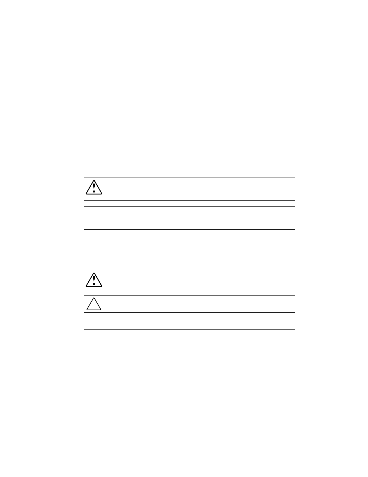
Library Features
Figures 1-1 through 1-3 shows some of the external features of the Library.
Control Panel
System Description 1-5
Magazine Door
Figure 1-1. Library front view
Power Switch
cc0052
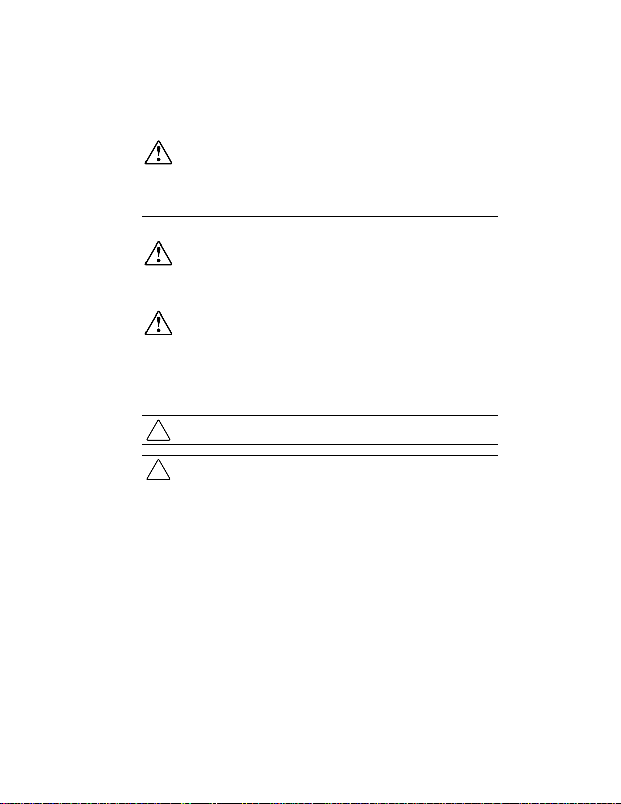
Page 18
1-6 Compaq StorageWorks SSL2000 Series LIbrary Maintenance and Service Guide
1
2
Expansion Ports
Diagnostic
3
4
Motor
5
Drive 2
6
Power Cord Connector
Drv 1 + LIB
cc0053
Figure 1-2. Library rear view
Control Panel
The control panel features a 4-line by 20-character backlit liquid crystal display, four LED
indicators a nd four button s. The buttons let you navigate through the menu structure to select
and display operating modes, device sta t us, diagnostic and maintenance functions, device
history and e rror statistics, and library system configuration.
Display
The backlit, 4-line by 20-character control panel display provides a highly intell igi ble
presentation of drive and loader status, menu choices, and error messages. The scrolling feature
greatly expands the amount of information available to the operator.
Power Supply
The AC power switch is located on the front panel of the uni t . The autoranging power supply
adjusts automatically to either of two operating voltage ranges. The ranges are 100-120 VAC
and 220-240 VAC. The power supply is capable of operat ing at 47 or 63 Hz without any
adjustment or modification. AC power is supplied to the power supply by a single
IEC-compatible socket, which can be connected to any properly gro unded outlet.
Lockdown Mechanism
Page 19
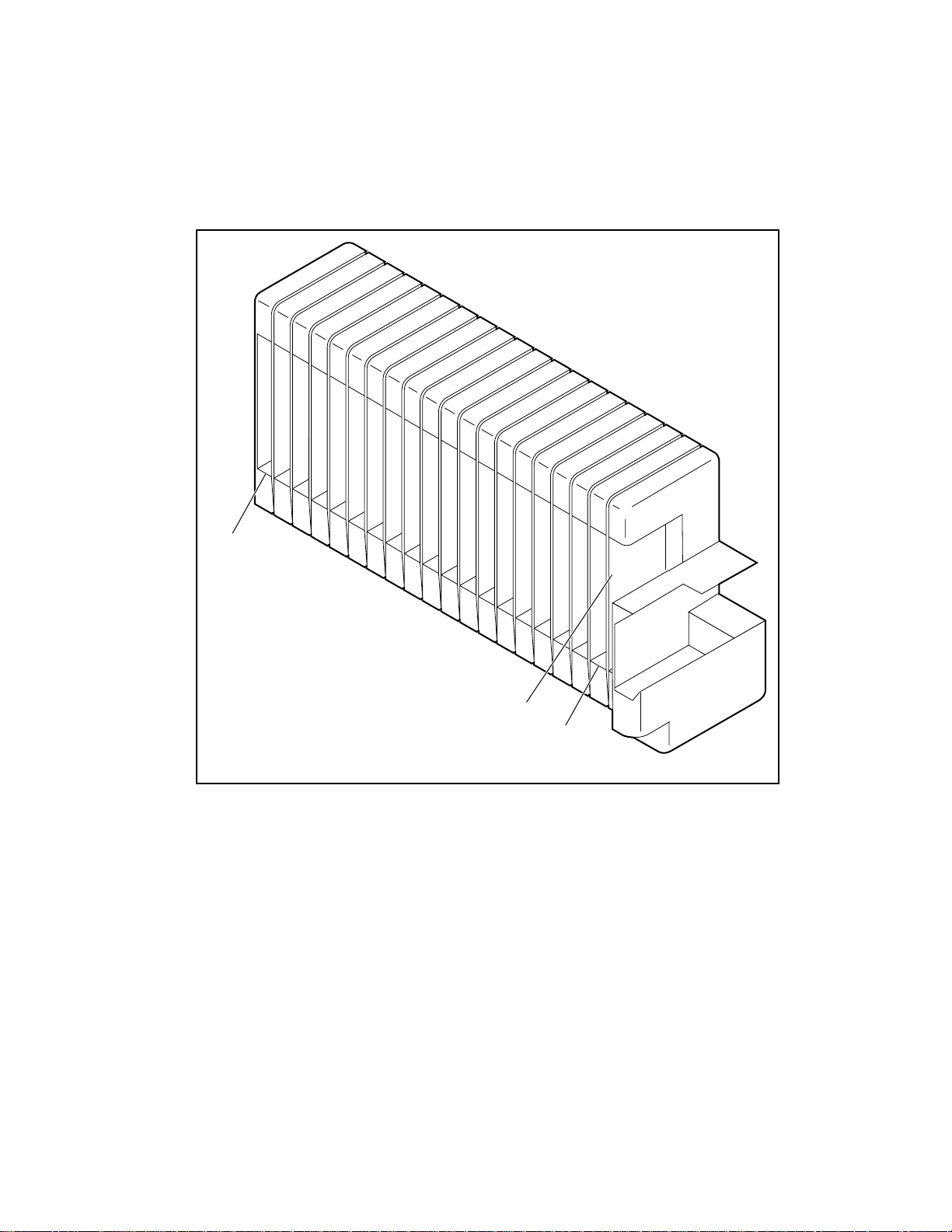
Tape Cartridge Magazine
The polymer magazine fits into an extruded track, which assures precise positioning for the
library robotics (see Figure 1-3).
Slot 18
System Description 1-7
Mail Slot
Slot 0
cc0054
Figure 1-3. Tape cartridge magazine
The front sl ot in the magazine is a Mail Slot, used to add or re move cartridges without
interrupting library operation. You can remove the magazine through the front door, but it is
protected from tampering in either of two ways:
■ An electronic combination lock, operated from the control panel
■ The host issuing a SCSI PREVENT/ALLOW MEDIUM REMOVAL command
For more information on inserting and removing the maga zine, see Cha pt er 2, “Operation.”
Page 20

1-8 Compaq StorageWorks SSL2000 Series LIbrary Maintenance and Service Guide
Integral Fan Cooling
Each AIT drive contains a ther mostat-controlled fan. I n addition, a fa n i s mounted inside the
Library to prevent critical parts from overheating.
Robotics
The Library features Compaq Mainframe-Class™ Library Robotics. These advanced robotics
can load any of the cartridges stored in the m agazine into any of the tape drives.
Bar Code Reader
A standard bar code reader is mounted on the cartridge shuttle. It reads bar code labels attached
to each cartridge, and maintains the bar code data in memory as part of the library system map.
Advanced Design Features
Embedded Diagnostics
The Library provides three levels of embedded diagnostics:
Power-On Self Test (POST )
configuration, host interface and device control functions, as well as memory tests when you
power on the unit.
User Diagnostics
panel.
CE Diagnostics
Library. Selected from front panel.
For more infor mation on user diagnostics, see Appendix C, “I nstallation.”
Error Checking
The drives used in the Library use read while write data checking and error-correction code
(ECC) technology such as is used in audio CD, DVD, and laser discs.
Buffer
Drives are equipped with an 8-MB buffer.
— Performs various verification tests on the system’s
— Lets you di splay and change configurati on options. Sel ected from fr ont
— Advance d di agnostics use d by Customer E ngineers (CEs) f or servicing the
Page 21

Compression
All drives used in the Library use the Adaptive Lossless Data Compression (ALDC data
compression algorithm developed by I B M).
Capacity
The Library with its 20-cartridge magazine offers the formatted capacities liste d in Table 1-5.
NOTE: Capacities are based on 19 storage slots.
System Description 1-9
Table 1-2
Tape Capacities
Media Life
Native Capacity Per Cartridge Per Cartridge Compressed
(2:1)
35 GB 70 GB 1,330 GB (665 native)
50 GB 100 GB 1,900 GB (950 native)
The media manufacturer r ates the media us ed in the Librar y at over 30,0 00 end-to-end passes
and specifies a shelf life of at least 30 years.
Full Magazine Compressed
(2:1)
Page 22

Introduction
This chapter describes operati ng the Compaq StorageWorks S S L2000 Series Library (AIT
Library) through the control panel at the front of the unit.
This chapter includes descriptions and or procedures for:
■ Front panel
■ LED indicators and buttons
Chapter 2
Operation
■ Front panel and media locks
■ Startup display message s
■ Using Library menus and modes
■ Displaying firmware revisions
■ Inserti ng and removing cartridges
■ Tape cartridge requirements
■ Bar code l abels
Page 23
2-2 Compaq StorageWorks SSL2000 Series Library Maintenance and Service Guide
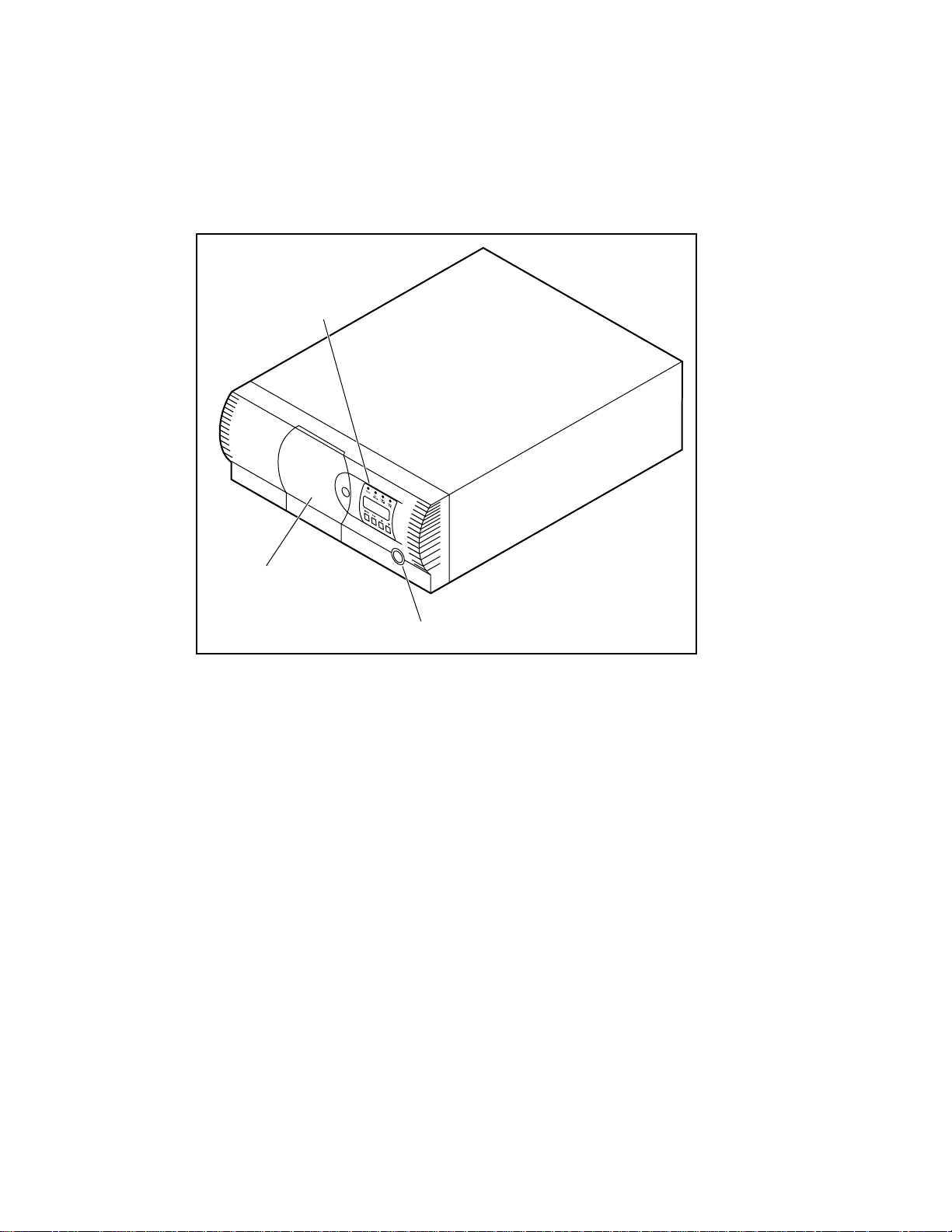
Front Panel
The front panel of the Libra ry includes a power switch for the unit an d t he control panel, which
has buttons, a display, and i ndicators (see Figure 2-1).
Control Panel
Magazine Door
Figure 2-1. Library front panel
Power Switch
The power swit ch controls the supply of A C power to the L ibrary front panel. It is a push-on,
push-off swit ch. When the power is on, the backplane of t he control pane l display lights.
Power Switch
cc0052
Page 24
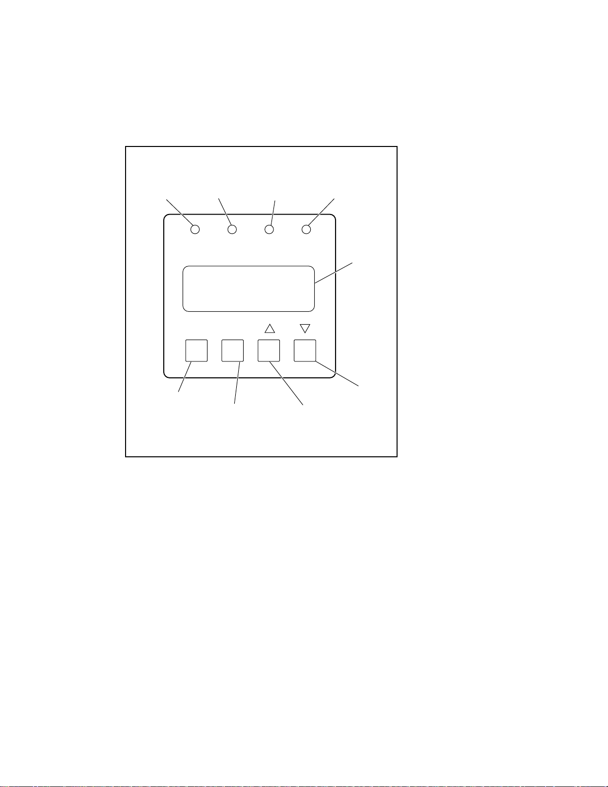
Indicators and Buttons
The control panel consists of four LED indicators, a four-line by 20-character backlit LCD
display, an d four buttons (s ee Figure 2-2).
Operation 2-3
234
Ready
(Green)
Use Cleaner
(Yellow)
Escape
(Navigate Menus)
Enter
(Select Menus)
Figure 2-2. Library control panel
Drive Fault
(Red)
Scroll Up
Loader Fault
(Red)
Display
Panel
Scroll Down
cc0055
Page 25

2-4 Compaq StorageWorks SSL2000 Series Library Maintenance and Service Guide
LED Indicators
There are four LED indicators on the control panel, labeled Ready (green), Use Cleaner
(yellow), Drive Fault (red), and Loader Fault (red).
The Ready LED (green) lights when the Library
computer. The Ready LED goes out when you enter the Menu mode, indicating that the Library
is offline.
The Use Cleaner LED (yellow) indicates that one or more of the drives in the Library
cleaning. Perform a cleaning operation as described in Chapter 5, “Maintenance.” When the Use
Cleaner LED lights, you can find out which drive needs cleaning by selecting Cleaning Needed
on the Drive Status submenu.
When either the Drive Fault or the Loader Fault LED (red) lights, a Fault screen appears on the
LCD display. The Fault screen is described later in this chapter.
See Chapter 4, “Troubleshooting,” for a list of Fault Symp tom Codes (FSC) and Error Recovery
Procedures (ERP).
Buttons
There are four buttons on the control panel: Escape
directly control specific functions or opt ions. Instead, you use the buttons to navigat e from the
Default screen through a multi-level menu structure, then select the desired option from the
appropriate menu using the Enter
under various conditions.
Using the Enter Button to Access Main Menu
Enter button. Table 2-1 lists the effect of each of the four buttons
EnterEnter
is ready to accept commands from the host
Escape, Enter
EscapeEscape
Enter, F
F, and GGGG. The buttons do not
EnterEnter
FF
needs
To enter the Menu mode and display the Main menu from the Default screen, press the Enter
button. When you enter the Menu mode, the Ready LED goes out. This means that the Library
is offline, and the Library
you exit the Menu mode and the Ready LED lights.
responds to all commands from the host with a SCSI Not Ready until
Using the Escape Button to Return to Default Screen
To return to the Main menu from a submenu, press the Escape
menu appears. Pressing the Escape
mode and returns you to the Default screen.
Escape button while the Main menu is displayed exi t s the Menu
EscapeEscape
Enter
EnterEnter
Escape button repeatedly until the Main
EscapeEscape
Page 26

Using the Escape Button to Access Status Mode
To enter the Status Mode, which displays all aspects of the Library’s operating and
configuration status, press the Escape
Escape button at the Default screen. The Library
EscapeEscape
Table 2-1
Control Panel Button Functions
Operation 2-5
remains online.
Display/Mode Escape Enter
At POST Screen N/A N/A N/A
At Default Screen Enters Status
Mode
In Status Mode
(while online)
In Menu Mode Rejects Currently
At Fault Screen N/A Clears Soft Errors N/A N/A
NOTE: There is an auto-repeat feature for the p and q buttons. When you press either button for
more than one-half second, the control panel behaves as if you were pressing and releasing the button
about four times per second. This effect stops when you release the button.
Returns to
Default Screen
Displayed Choice,
or
Aborts Control
Panel Operation
In Progress, or
Exits to Next
Higher Menu
Level, or
Exits Menu Mode
to Default Screen
Enters Menu
Mode
Same as in Menu
Mode
Accepts Currently
Displayed Choice
pq
Toggles between Page 1
and Page 2
Same as in Menu Mode
Moves u 1 Line
Upward Through
List of Options, or
Scrolls Part of
Display 1 Line
Toward Top of
List of Options
Moves u 1 Line
Downward
Through List of
Options, or
Scrolls Part of
Display 1 Line
Toward Bottom of
List of Options
Front Panel and Media Locks
A security feature is available to avoid accidental interruption of Library operation by entering
the Menu mode or removing cartridges while the host is accessing the Library. The front panel
and the media can be electronically locked. When the front panel is locked, you can only enter
the Menu mode after entering a 4-digit code. That is, when the Default screen appears, pressing
the Enter
Enter button does not invoke the Menu mode until you enter the code. The front panel
EnterEnter
cannot be unlocked without using the Security submenu to un lock it.
The media can also be locked by software running on the host, using the SCSI
ALLOW/PREVENT MEDIUM REMOVAL command. The Library
override for this command. Usually, exiting the host software restores media access. In the event
of host failure, you can restore media access by cycling the Library
Procedures for locking and unlocking front panels and media are described later i n this chapter.
provides no c o ntr ol pa ne l
power.
Page 27

2-6 Compaq StorageWorks SSL2000 Series Library Maintenance and Service Guide
Startup Display Messages
The display on the control panel is capable of displaying four lines of 20 characters ea ch, to
allow the use of easy-to-understand messages. Many of these messages and their functions are
described in this chapter. Those displays t hat are described in other chapt ers are crossreferenced here as well.
Power-On Self Test Screen
When power is first applied to the module, a series of Power-On Self Test (POST) diagnostics
are performed. During POST execution, the model number of the module, the firmware
revision, and the status or result of the test in progres s are displayed on the control panel as
shown:
Compaq SSL2020TL
Firmware Level 0X.XX
Checking Hardware
Initialization Screens
After the POST completes, the library robotics are initialized. A series of screens similar to the
one shown is displa yed d ur in g this pr oc e ss.
Compaq SSL2020TL
Firmware Level 0X.XX
Initializing Loader
Page 28

Default Screen
After the POST diagnostics have concluded successfully and initialization is complete, the
following Default screen appears. Note that the Default screen consists of two pages.
Page 1 Default screen:
Page 2 Default screen:
Page 1 displays the library and drive status. Page 2 displays the library sta tus (Line 1) an d
magazine slo t status (Lines 3 and 4).
The library status lines show each slot as a rectangle. A solid block indicates that a cartridge is
present. A h ollow block indicates that a slot is empty.
Loader Idle
Drv0: Ready or No Tape
Drv1: Idle
Loader Idle
0 _ _ _ _ _ _ _ 9
10
_ _ _ _ _ _ _ 18
Operation 2-7
Line 4 also shows the status of the mail slot. A
slot. A
The
Fault Screen
When a fault is detected, a screen similar to the one shown appears. In addition, either the Drive
Fault or the Loader Fault LED on the control panel lights.
The first line shows a numeric al FSC. The seco nd l ine shows a bri ef description of the error.
The third and fourth lines contain a one- or t wo-line message describing t he initial ERP.
For a list of FSCs and ERPs, see Chapter 4, “Troubleshooting.”
symbol indicates that a cartridge is in the mail
symbol indicates that the mail slot is empty.
F
F, and GGGGbuttons cont rol which Default page is displayed.
FF
Fault Code: 3004
Elevator Jammed
Power Down to Clear
Page 29
2-8 Compaq StorageWorks SSL2000 Series Library Maintenance and Service Guide
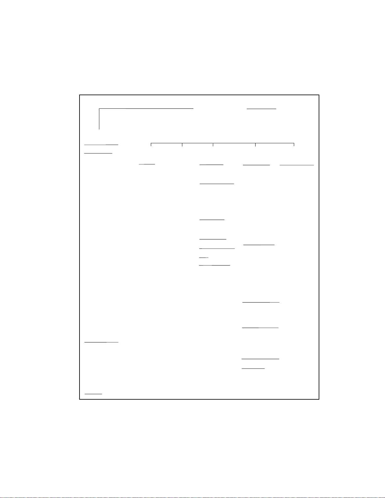
Using the Library Menus
Use the Library menus (Fig ure 2-3) to dis pl ay status information and to operate and co nfigure
the Library.
Power-Up Displays
Default Display
Fault Display
Status Mode
Access Mail Slot
Library Status
Model Number
Firmware Revision
SCSI Bus ID
SCSI Bus Parity
Boot Version
Flash T ype
Library T ype
Library Mode
Library Config
Vendor ID
Product ID
Baud Rate
Transport Addr
Storage Addr
Transfer Addr
Import/Export
Serial Number
Negotiation Mode
Transfer Rate
Unload Mode
Auto Clean Mode
Reserved Slots
Mode Page 1F Length
TUR Reporting
Init Elem Status
Bar Code Reader
Label Size
Label Alignment
Loader Status
SCSI Mode
Post Recv'd Error
Tape Alert Mode
Drive n Status
Tape Motion
SCSI Bus ID
Firmware Revision
Cartridge Preset
Hardware Error
Cleaning Needed
Write Protected
Map Info
Escape Button
Load/Unload
From/To
Remove
Magazine
Enter Button
Panel Lock
Main Menu
Maintenance
Menu
Clean Drive
Cleaning
Using
Diagnostic Menu
Cartridge Cycle
Friction Test
Tach Feedback
Scanner Feedback
Scan Labels
Demo Menu
Demo 1
Demo 2
Flash Update
NOVRAM Update
Park
Reboot Module
Configuration
Menu
SCSI Options
Library Parity
Library Bus ID
Drive 0/1 Bus ID
Vendor ID
Product ID
Negotiation Mode
Transfer Rate
Mode Pg 1F Length
Init Elem Status
Unit Attn Report
SCSI Mode
Post Recv'd Error
Tape Alert Mode
Library Options
Configuration
Unload Mode
Numbering
Element Base
Auto Clean
Library Mode
Baud Rate
Reserved Slots
Model Number
Bar Code Options
Label Size
Label Alignment
Check Digit
Set Element Base
Transport
Storage
Transfer
Import/Export
Set Serial Number
Set Default
Compaq Defaults
Security Menu
Set Unlock Code
Figure 2-3. Library menus
Page 30

Using the Status Mode
Operation 2-9
You can enter the Status Mode by pressing the Escape
appears. Entering the Status Mode does not affect operation of the Library. When you enter the
Status Mode, the following appears:
u Access Mail Slot
Library Status
Drive 0 Status
Map Info ¤
Exiting the Status Mode
To exit the Status Mode, press the Escape
Escape
Escape button again to display the Defa ult screen.
EscapeEscape
Exploring the Status Mode
The functions available in the Status Mode are:
■ Access Mail Slot
■ Library Sta tus
■ Drive
■ Map Info
Scroll up or down with the
n
Status
Escape button whenever the Default screen
EscapeEscape
Escape button until the Status menu appears. Press the
EscapeEscape
p and q buttons and press the Enter
Enter button to select the item.
EnterEnter
Library Status Submenu
When you selec t Library Sta t us, the following menu appears:
Model Number:
Compaq SSL2020TL
Firmware Revision:
03.03 ¤
Page 31

2-10 Compaq StorageWorks SSL2000 Series Library Maintenance and Service Guide
Scroll through this screen to view the list of available options:
■ Model Number ■ Negotiation Mode
■ Firmware Revision ■ Transfer Rate
■ SCSI Bus ID ■ Unload Mode
■ SCSI Bus Parity ■ Auto Clean Mode
■ Boot Version ■ Reserved Slots
■ Flash Type ■ Mode Page 1F Length
■ Library Mode ■ TUR Reporting
■ Library Config ■ Initialize Element Status
■ Vendor Iden ■ Barcode Reader
■ Product Iden ■ Label Size
■ Baud Rate ■ Label Alignment
■ Transport Address ■ Loader Status
■ Storage Address ■ SCSI Mode
■ Transfer Address ■ Post Recv’d Error
■ Import/Export Addr ■ Tape Alert Mode
■ Serial Number
Drive Status Menu
When you select either of the drives, the following menu appears:
u Tape Motion:
Idle
SCSI Bus ID:
4 ¤
Scroll through this screen to view the list of available options:
■ Tape Motion
■ SCSI Bus ID
■ Firmware Revision
■ Cartridge Present
■ Hardware Error
■ Cleaning Needed
■ Write Protected
Page 32

Map Information Screen
When you select Map Info, the following screen appears. The location being reported appears
on Line 1. The content of the bar code on the l abel, up to 6 characters, ap pears on Line 4.
Drv 0
Occupied
Label Valid
XXXXXXXX ¤
The list of locations available for display on line 1 is as follows. If yo u do not designat e any
mail slots, those lines are omitted from the list.
■ Drive0
■ Drive1
■ Slot0
■ Slot1
■ . . .
■ Slot18
■ Mail Slot
Operation 2-11
Depending on the report for each location, Line 2 might display either Empty or Occupied, or, if
a magazine is absent, Not Installed. Depending on the report for each location, Line 3 might
display either Label Valid, or Label Not
For each location reported, Line 4 displays the actual bar code on the label, up to 6 characters.
Using the Menu Mode
NOTE: When the Library enters the Menu mode, the Ready LED goes out. This means that the module is
offline, and responds to all commands from the host with a SCSI Not Ready until you exit the Menu Mode
and the Ready LED comes on.
To prevent int erruption of host operations, you can lock out the Menu Mode using the Security
menu. See “Security Menu” later in this chapter. When all control panels are locked, you must
enter your unlock code to display the Main menu.
When the Default screen appears, you can enter the Menu Mode by pressing the Enter
The followi ng Main menu appears:
u Load/Unload
Remove Magazine
Maintenance Menu
Configure Menu ¤
NOTE: If the control panel has been locked, the following screen appears instead of the one shown
above. You must know the unlock code for the Library before you can continue.
Present.
Enter button.
EnterEnter
Front Panel Locked
ENTER to Unlock
ESCAPE to Exit
Page 33

2-12 Compaq StorageWorks SSL2000 Series Library Maintenance and Service Guide
When you pre ss the Enter
Unlock Code £
“
¤
Using the p and the q b utt on, set the first digit of the unlock code. Press the Enter
move the cursor to the second digit and repeat the process. Press the Escape
Enter
Enter button to confirm your entry. If the code is correct, the Main menu appears. If the code is
EnterEnter
incorrect, an error screen appears.
Enter button, the following screen appears:
EnterEnter
Exiting the Menu Mode
To exit the Menu Mode and return to the Default screen, press the Escape
Each time you press the Escape
Main menu appears, pressing the Escape
the Ready LED lights.
Escape button, the display moves to a hi gher menu level. When the
EscapeEscape
Escape button once returns to the Default screen. At this point,
EscapeEscape
Navigating through the Menu Structure
To select a submenu, move the u on the display to the desired line using the pand q buttons.
Press the Enter
fourth line means you can scroll to additional configuration option s with the
Enter button to select your choice and display the submenu. The
EnterEnter
Enter button to
EnterEnter
Escape button, then the
EscapeEscape
Escape button repeatedly.
EscapeEscape
¤ at the end of the
q button.
The options available on the Main Menu are:
■ Load/Unload
■ Remove Magazine
■ Maintenance Menu
■ Configur ation Menu
■ Security Menu
Load/Unload Menu
See “Loading and Unloading Tapes,” later in this chapter.
Remove Magazine Menu
When you scroll to Remove Magazine and press the Enter
open.
NOTE: If the message Magazine Locked appears on the screen, the host software has locked the
magazine. Exiting your backup or host management software usually releases the lock. (The host
management software should have a way to release the magazine without shutting down.) If the host
fails, you can cycle power to the Library to release the lock.
Enter button, the magazine door swings
EnterEnter
Page 34

Maintenance Menu
The Maintenance menu options, intended for operator use, are described in Chapter 3,
“Maintenance.”
Configure Menu
The Config ure menu, how to use it, and the options available under it are describe d i n Appendix
C, “Installat ion.”
Security Menu
Use the Securi ty menu to lock the control panel. This pre vents inadvertent or unauthorized
access to the Menu Mode, which takes the Library offline.
NOTE: You can display the Show Status menu without unlocking the panel (and without taking the
Library offline) by pressing the Escape button at the Default screen.
When you select the Security menu, the following screen appears:
u Set Unlock Code
Set Mail Slot Code
Operation 2-13
The Security Menu includes the following options:
■ Set Unlock Code
■ Set Mail Slot Code
To change the unlock code, or to enable or disable the panel locking function, scroll downward
to Set Unlock Code. Press the Enter
Unlock Code £
*“0000”
0000 Disables Lock ¤
An underline cursor displays under the first digit. To set the first digit, press the p but ton or the
q button until the number you want appears. To move the cursor to the second digit, press the
Enter
Enter button. Repeat the process for each of the four digits. Be sure to remember the 4-digit
EnterEnter
number; yo u use it to enter the Menu Mode. Use an unlock code of 0000 to disable control panel
locking.
When you have finished entering four dig its, press the Escape
appears. Your code appears instead of XXXX.
Unlock Code £
*“XXXX”
ENTER to Accept
ESCAPE to Exit ¤
Enter button. The following screen appears:
EnterEnter
Escape button. The follow ing screen
EscapeEscape
Page 35

2-14 Compaq StorageWorks SSL2000 Series Library Maintenance and Service Guide
Press the Enter
Enter button to accept the displayed unlock code or Escape
EnterEnter
Escape to return to the Main
EscapeEscape
menu.
The next time you try to enter the Menu Mode , the followin g screen appear s. You can still
display the St atus menu without using the security code by pressing the Escape
Escape button at the
EscapeEscape
Default screen.
Front Panel Locked
ENTER to Unlock
ESCAPE to Exit
When you pre ss the Enter
Unlock Code £
“ “
¤
Using the p and q buttons, set the first digit of the unlock code. Press the Enter
Enter button, the following screen appears:
EnterEnter
Enter button to
EnterEnter
move the cur s or to the secon d digit and repea t the process. W hen you have finished, press the
Escape
Escape button. The following screen appears:
EscapeEscape
Unlock Code
*“XXXX”
ENTER to Validate
ESCAPE to Exit
Press the Enter
Enter button to validate your choice. If the code is correct, the Main menu appears. If
EnterEnter
the code is incorrect, an error screen appears. If you forgot your unlock code, contact your
Technical Support representative for assistance.
Displaying Firmware Revisions
You can display the library robotics firmware revision a t any time by pressing the Escape
at the Default screen to enter the Status Mode. It displays as one of the options on the Library
Status subme nu of the Status menu. It is also displ ayed on line 2 of the POST Screen a nd the
Initialization Screens.
Loading and Unloading
The Load/Unload menus let you specify a s ource and a dest ination for a ca rtridge movem ent, so
you use exact ly the same procedure to load and unload. To load or unloa d a tape from the front
panel, use the Load/Unloa d menus as follows:
Ready
0
_ _ _ _ _ _ _ 9
10
_ _ _ _ _ _ _ 18
Escape button
EscapeEscape
Page 36

Operation 2-15
From the Default screen, enter the Menu Mode by pressing the Enter
Main menu appears with the
u next to Load/Unload.
Enter button. The following
EnterEnter
u Load/Unload
Remove Magazine
Maintenance Menu
Configure Menu ¤
Press Enter
Enter to di splay the first Load/Unload submenu, as shown.
EnterEnter
From:
u *Slot 1
To
*Drv0 ¤
The u is next to line 2 of the displa y. Line 2 shows the top item in a sc rollable list of sources.
Note that a
¤ has appeared on the right of the bottom line. This indicates that the q button can
now be used to scroll through the list, and that the top item on the list is displ ayed. As soon as
you press the
q button, the following three things happen:
1. The list scrolls down one item (only line 2 scroll s) .
2. An £ displays on the right of line 1, meaning there are more options above the item
displayed on line 2.
3. The * at the left of line 2 (the c urrent selection) disappear s, meaning you have not selected
an item from the list.
NOTE: The contents of the lists on line 2 and line 4 vary as follows.
Initial Screen – From Line
The list on line 2 (the From line) includes every drive and magazine sl ot (including mail slots)
with cartridges. (You cannot retrieve a cartridge from an empty slot or drive.)
Initial Screen – To Line
The list on line 4 (the To line) includes all the valid destina tion choices, that is, drives and slots
that are empty. (You can’t put a cartridge into a full slot or drive.)
Scroll List – To Line
There is another limitation on the To list. If you select a drive on the From screen, the To list
can include only slots. If you select a slot on the From screen, the To list can contain only
drives.
For example, load the cartridge that is in Slot 11 into any available drive. Use the
scroll line two to Slot 11. The following screen appears:
From: £
u Slot 11
To:
Drv 0
q button to
Page 37

2-16 Compaq StorageWorks SSL2000 Series Library Maintenance and Service Guide
When you scroll to your desired source, press the Enter
Enter button to select it. Two changes occur in
EnterEnter
the display as shown belo w:
■ The * reappears at the beginning of line 2, indicati ng that you have made a select i on.
■ The u moves to line 4, indicating that you can select a desti nation.
From:
*Slot 11
To:
u *Drv 0
Press the Enter
Enter button to select Drive 1 as the destination. The following Confirmation Screen
EnterEnter
appears:
From: Slot 11 To: Drv 0
ENTER to Execute
ESCAPE to Cancel
Press the Enter
Enter butt on to execute the load or unload or the E s cape
EnterEnter
Escape button to cancel or return to
EscapeEscape
the From entry screen.
When you pre ss the
Enter
Enter button, the following screen appears: If the source is a drive, the word
EnterEnter
Unload appears in place of the word Load on line 4.
From: Slot 11 To: Drv 0
Load In Progress
When the load or unload operation completes, the Default screen reappears.
Inserting and Removing Cartridges
The tape magazine must be r emoved from the Library in order to remove or insert cartridges
(see Figure 2-4). Make sure t he slot you want t o use is not already reserved for a cartridge that is
now in a drive. The safest way to do this is to unload all drives before removing the magazine.
You can unload all the drives either through your host computer software or by using the
LOAD/UNLOAD command on the Main menu.
Make sure the control panel is unlocked. When the control panel is locked, it is impossible to
enter the Menu Mode. The host computer must allow removal of the magazine. The host
software can enable or disable the door unloc k function using the SCSI PREVENT/ALLOW
MEDIUM REMOVAL command. If the host is preventing removal, when you select Unlock
Door on the Main menu and pr ess the Enter
Enter button, the message Magazine Locked appears.
EnterEnter
Page 38

The host software should be able to release the magazine without shutting down. If ho st
computer failure prevents the host from releasing the lock, cycle power to the Library.
IMPORTANT: If you are still unable to open the magazine door, see “Emergency Magazine Removal,”
later in this chapter.
Magazine In
1
Place
R
e
a
d
y
U
s
C
e
l
e
a
n
e
r
D
r
i
v
e
F
a
u
l
t
L
o
a
d
e
F
r
a
u
l
t
E
s
c
a
p
e
E
n
t
e
r
Operation 2-17
Figure 2-4. Magazine in place
Removing the Magazine
Whenever a magazine is installed inside the module it is locked in place to prevent tampering or
accidental removal. To remove the magazine, enter the Menu Mode by pressing the Enter
at the Default screen. At the Main menu, select Remove Magazine, and press the Enter
The magazine door swings open.
Emergency Magazine Removal
If a fault occurs that prevents removal of the magazine, turn the power off for five seconds.
Power up while continuously pressing the
indicators on the control panel light, then go out. Release the button. The door swings open.
cc0056
Enter button
Enter Enter
Enter button.
EnterEnter
p button. Continue to hold the button until all of the
Page 39

2-18 Compaq StorageWorks SSL2000 Series Library Maintenance and Service Guide
Inserting Cartridges into the Magazine
A full magazine is shown in Figure 2-5. Insert cartridges so that the label end with the write
protect switch is outward, with the write protect switch toward the bottom of the ma gazi ne. The
lowest numbered cartridge slot in the magazine is closest to the handle. The highest numbered
cartridge sl ot is the farthe st from the handle.
Slot 18
1
Figure 2-5. Tape magazine with cartridges installed
Inserting the Magazine
If the magazine door on the front of the Library is closed and locked, open it, as follows. Enter
the Menu Mode by pressing the Enter
Remove Magazine and press th e Enter
magazine through the door opening, with the cartrid ges protruding from the left. When the
magazine is fully inserted, push the door closed until it locks.
2
Slot 0
cc0057
Enter button at the Default screen. At the Main menu, select
EnterEnter
Enter butt on. The magazine door swings open. Slide the
EnterEnter
Page 40
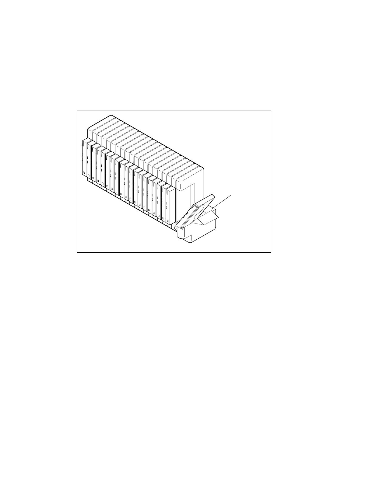
Using the Mail Slot
The mail slot is used only with host software that supports this feature (Figure 2-6). To access
the mail slot from the Default screen, press the Escape
Enter
Enter button and the magazine door opens, exposing the Mail Slot. The magazine remains
EnterEnter
locked inside the module. T he mail slot of the magazine can be tilted forward to insert or
remove a car tridge. After inserting or removing the cartridge, close the magazine door.
Operation 2-19
Escape button to enter the Status Mode. Press the
EscapeEscape
Figure 2-6. Mail slot location
Tape Cartridge Requirements
The Library uses Advanced Intelligent Tape (AIT) 8 mm tape cartridges. They are designed for
an MTBF of 250,000 hours.
NOTE: Handle and store tape cartridges in a clean, dust-free environment.
cc0058
Mail Slot
1
Page 41

2-20 Compaq StorageWorks SSL2000 Series Library Maintenance and Service Guide
Write Protecting Cartridges
To write protect a tape cartridge (disable data recording), slide the write protect switch up so
that no oran ge color is visibl e in the lower small window (see Figure 2-7). To enable data
recording, slide the write protect switc h down until the orange indica tor shows in both small
windows.
Figure 2-7. Tape cartridge write protection switch
SAFE
REC
cc0011
Page 42
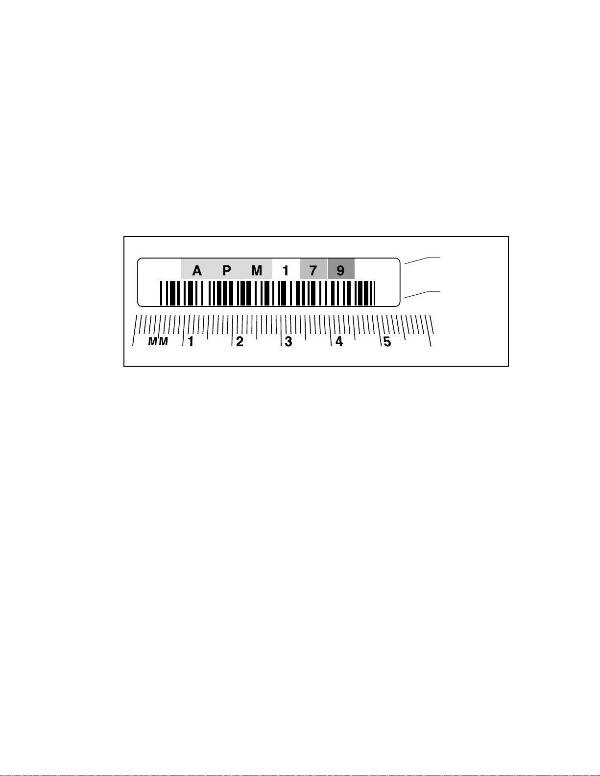
Bar Code Labels
Bar code labels should meet the following specifications (see Figure 2-8):
■ Size: 2.1 in x 0.4 in (55 mm x 10.2 mm)
■ Stock: Label stock with adhesive back and matte overla minate
■ Location: Mounts next to write-protec t switch on car tridge
■ Text: Six characters, any combination of alphabetic and numeric
■ Bar Code: Code 39, Codaba r, 3-of-9, standard 2-of-5, or interleave d 2-of-5, with a length
of eight digits. Minimum e lement width is 0.3 in (7.5 mm)
Operation 2-21
Figure 2-8. Bar code label size
Label Size
10.2 mm
cc0059
55 mm
x
2
1
Page 43

2-22 Compaq StorageWorks SSL2000 Series Library Maintenance and Service Guide
Multi-Unit Library System Operation
Powering Up
All Library units should be powered up at the same time through the storage cabinet supplied
power, or the master unit (t op) should be pow ered up last if the Library units are powered up
individually.
Connecting a Multi-Unit Library System
The following procedure explains how to set the SCSI ID and SCSI host conne ctions:
1. For maximum performance, connect only 2 AIT-2 drive s t o each SCSI host adapter.
2. For nominal performance, you can connect 3 AIT-2 drives per host.
3. Set the SCSI IDs through t he master unit front panel dependent on the SCSI host adapter
drive ratio.
4. On the master unit, the Library will take up a SCSI ID (default is 0).
5. AIT dri ves on different SCSI host adapters can have the same ID.
NOTE: If you use only two drives per SCSI host adapter, leaving the default setting will work provided
there is no conflict with any other devices.
Page 44

Introduction
This chapter describes the Clean Drive and Demo options contained in the Maintenance menu.
Use the Clea n Drive option t o clean tape drives installed in the Compaq StorageWorks SSL2000
Series Library (AIT Library). Use the Demo option to fully exercise the Library robotics.
IMPORTANT: Perform the Clean Drive option from the Maintenance menu only when the Library displays
a message informing you that a drive needs cleaning.
Chapter 3
Maintenance
NOTE: When Compaq introduces new Library firmware, a qualified service technician must install it.
This chapter includes procedures for:
■ Running a cleaning cartridge
■ Removing the cleaning cartridge
■ Exercising the Librar y robotics
Running a Cleaning Cartridge
There are two ways to run a cleaning cartridge:
■
Automatically
■
Manually
on the front panel displa y
—by enabling the Auto Clean option
—by selecting the CLEAN DRIVE command from the Maintenance submenu
Page 45

3-2 Compaq StorageWorks SSL2000 Series Library Maintenance and Service Guide
Running a Cleaning Cartridge Automatically
You can configure the Library so that it runs the cleaning cartridge automatically. Because the
cleaning cartridge is abrasive, you should not use it unless Use Cleaner appears on the control
panel screen. The completion of an unload operation on a drive that needs cleaning causes the
Use Cleaner LED to light. This in turn activates an automatic cleaning cycle if Auto Clean has
be selected f rom the Configuration menu.
To run a cleaning cartridge automatically using Auto Clean:
1. Reserve a slot as the cleaning slot:
See “Setting U p Reserved Slots” i n Appendix C.
If you have m ore than one reserved slot, the Cl eaning Slot is the first reserve d slot.
Reserved slots are at the back of the magazine.
2. Install a cleaning cartr idge into Reserved Slot #1.
3. Enable the Auto Clean option on the Configuration menu:
From the Main menu, select Library Options / Auto Clean / Enabled.
Running a Cleaning Cartridge Manually
1. Install the cleaning cartridge into any slot. (Slot 0, for example.)
2. At the Default screen, press the Enter
u Load/Unload
Remove Magazine
Maintenance Menu
Configure Menu ¤
3. Scroll down to the Maintenance menu and press the Enter
Maintenance su bm e nu a ppea rs :
u Clean Drive
Diagnostic menu
Demo Menu
Flash Update ¤
Press the Enter
4.
appears:
Cleaning:
u *Drv 0
Using:
*Slot 0
5. Press the Enter
available on L ine 4 are slots 0 through 18. Press the Enter
in Slot 0.
Enter button once to select Clean Drive. The following Cleaning submenu
EnterEnter
Enter button to accept Drive0. The K moves to line 4 of the display. T he choices
EnterEnter
Enter button. The following Main menu screen appears:
EnterEnter
Enter button. The following
EnterEnter
Enter button again to use the cartridge
EnterEnter
NOTE: If you cannot use slot 1 for the cleaning cartridge, you can scroll line 4 to select another slot.
Page 46

Maintenance 3-3
6. The following Cleaning Confirmation screen appea rs:
Cleaning: Drive 0
Using: Slot 0
ENTER To Execute
ESCAPE To Cancel
7. As the Cleaning Confirmation screen indicates, to execute the cleaning operation, press
the Enter
Enter button. If the Cleaning Confirmation screen does not show your intended drive
EnterEnter
and cleaning cartridge, press the Escape
Escape button to return to the Cleaning submenu.
EscapeEscape
When you pre ss the Enter
Cleaning: Drive 0
Using: Slot 0
Cleaning In Progress
When the cleaning operation completes, the Default screen reappears.
Enter button, the following Cleaning In Progress screen appears:
EnterEnter
Removing the Cleaning Cartridge
1. Examine the Default screen on the control panel to make sure the cleaning cartridge has
been unloaded from the dr ive. If not, then unload it using the Load/Unload menu, as
described in Chapter 2, “Operation
2. Remove the magazine from the Library. See “Inserting and Removing Cartridges” in
Chapter 2.
3. Remove the cleaning cartridge from the magazine.
4. Insert any desired data cartridge into the slot vacated by the cleaning cartridge.
5. Insert the magazine into the Library.
6. Close the magazine door.
Exercising the Library Robotics
.
”
To fully exercise the library robotics, use the Demo option as follows:
1. From the Maintenance menu, select the Demo submenu.
2. Select Demo 1.
The library robotics begi n to move cartr idges randomly from slot to slot, displaying the number
of passes on the screen.
If all slots in the magazine are full, Demo 1 loads a cartridge into DLT0 and leaves it there. If
you press the
unless DLT0 is full. If you press the
returned to the magazine.
Demo 1 runs continuously as long as the Library has power.
To pause Demo 1, press and ho l d the Escape
test is paused.
To stop Demo 1, press the Es cape
F button whi le Demo 1 is running, the Library loads a cartridge into DL T0,
F button again, the cartridge is unloa ded from DLT0 a nd
Escape button until a flashing message displays that the
EscapeEscape
Escape button a second time to return to the Main menu.
EscapeEscape
Page 47

Introduction
This chapter describes the problems that can cause the Compaq StorageWorks SSL2000 Series
Library (AIT Library) t o malfunction, including:
■ Platform problems
■ General drive errors
■ Error recovery
■ Fault Symptom Codes (FSCs)
Chapter 4
Troubleshooting
Platform Problems
Incorrect installation and configurat ion cause platform problem s . In this case, the Library
appears to be operating nor mally, but no data can be int erchanged. You may or may not get an
error code on the control panel. To identify an error ca used by this t ype of problem, check your
installation and configur ation setup. See Appendix C, “ Installation,” for more information.
General Drive Errors
General drive errors usua lly result from a miscommunic ation between a module’s processor and
a drive processor or a mechanical malfunction within the Library.
Both platform problems and general drive errors display an error messa ge and a Fault Syste m
Code (FSC) on the control panel. Use the FS C t o report errors to your Techni cal Support
representative, or in some cases, to determine a recovery procedure.
A simple error recovery procedure appears at the bottom line of the control panel display. You
can clear some errors by pressing the Enter
to the Library.
Enter butt on on the control panel or by cycling the p ower
EnterEnter
Page 48

4-2 Compaq StorageWorks SSL2000 Series Library Maintenance and Service Guide
Error Recovery
Figure 4-1 outlines the recommended steps for error recovery. You should follow this chart in
all cases.
Error Recove ry Procedures (ERPs) are listed in detail in Table 4-1; FSCs are l isted in Table 4-2.
An ERP is also listed for each FSC.
TROUBLESHOOTING
AND ERROR RECOVERY
ERROR, FAULT, MALFUNCTION
Determine Suspected Error Type
PLATFORM
No FSC displayed. Normal front
panel operation
Cycle the power
to the library
Retry
Check configuration in Appendix C
FSC might/might not be displayed
Normal operation impossible
Figure 4-1. Troubleshooting flowchart
GENERAL DRIVE
FSC and ERP displayed on
control panel
Follow the ERP on
the control panel
Find FSC in Table 4-2
Follow the ERP in Table 4-1
CARTRIDGE ERROR
Cartridge will not eject
cc0060
Page 49

Error Recovery Procedures
Table 4-1 lists ERPs for err ors reported o n the front panel of the Librar y.
ERP Code Procedure/Description
C Cycle power to the Library using the AC switch on the front panel. Wait 30
seconds to power on again.
D Turn off power to the Library and inspect connectors and cables.
F Invalid operation. Select parameters correctly and try again.
Fault Symptom Codes (FSCs)
FSCs that appear on the Fault screen are described in Chapter 2, “ Operation.” A descriptive
message and instructions for clearing the fault accompany each FSC. If a fault persists, look up
the FSC in Table 4-2 to determine the error recovery proce dure.
Troubleshooting 4-3
Table 4-1
Error Recovery Procedures
Table 4-2
Fault Symptom Codes
FSC Message ERP
3001 Picker Tries Escd
Power Down to Clear
3002 Picker Tach Errors
Power Down to Clear
3003 Elevator Tach Errors
Power Down to Clear
3004 Elevator Jammed
Power Down to Clear
3005 Picker Jammed
Power Down to Clear
5002 All Drives/Slots Empty
Press Enter to Clear
5003 All Drives/Slots Full
Press Enter to Clear
C,D
D
D
C,D
C,D
F
F
continued
Page 50

4-4 Compaq StorageWorks SSL2000 Series Library Maintenance and Service Guide
Table 4-2
Fault Symptom Codes
FSC Message ERP
continued
5012 All Drives Full
Press Enter to Clear
5014 AIT Already Loaded
Press Enter to Clear
5015 Expired Cleaning Cart
Press Enter to Clear
5016 Not a Cleaning Cart
Press Enter to Clear
F
F
F
F
If an error message that is not included in Table 4-2 appears, write down the fault code number
and follow the recovery procedure described on line 4 of the display.
Page 51

Introduction
This chapter describes procedures for removing and replacing Field Replaceable Units (FRUs)
for the Compaq StorageWorks SSL2000 Series Library (AIT Library). For a complete list of
FRUs, spare parts, accessories and part numbers, see “Appendix B” of this manual.
FRUs
■ Bar code reader
Chapter 5
Parts Removal and Replacement
■ Controller board
■ Door solenoid
■ Tape drive
■ Fan assembly
■ Front panel
■ Magazine guide
■ Magazine latch solenoid
■ Power su pply assembly
■ Power switch
■ Shuttle assembly
■ Pass-through mechanism (PTM)
Page 52

5-2 Compaq StorageWorks SSL2000 Series Library Maintenance and Service Guide
Precaution
■ You should be trained and authorized to perform these procedures.
■ Before performing any of the following procedures, take all appropriate precautions to
prevent damage from Electro-Static Discharge (ESD).
■ Always disconnect AC power before working on any of the Library in t ernals.
■ When any procedure req uires you to manually move the shuttle assembly, always pu sh the
assembly from the bottom and never from the top.
Ferrites
To protect against Electro-Magnetic Interference (EMI), many cables are equipped with
attached ferrite assemblies. The ferrite cores are encased in two-part plastic enclosures that clasp
shut around the cables. You wi ll find moving cables easier if you remove an obstructing ferrite.
If so, pry the enclosures open gently in order to not break the clasps. Be sure to reposition each
ferrite after you complete the replacement procedures.
Using Loctite 222
All screws that do not use lock washers, captive washers, or lock nuts must have Loc tite 222
applied when re-assembled in the field.
NOTE: If you neglect this step, the mechanism could fail prematurely.
Some parts have been assembled using screws with Loctite applied. You will have to use extra
torque when removing these screws. Be careful not to strip them. Spare screws are included in
most FRU kits.
Page 53

Removing and Replacing the Bar Code Reader
To remove the bar code reader:
1. Pushing only from the bottom of the assembly, move the shuttle thr ee or four inches from
the front panel.
2. Pushing only from the bottom of the assembly, move the picker as close as you can toward
the magazine (see Figure 5-1).
Parts Removal and Replacement 5-3
Figure 5-1. Moving the shuttle assembly
cc0070
Page 54

5-4 Compaq StorageWorks SSL2000 Series Library Maintenance and Service Guide
3. Disconnect the bar code reader cable (see Figure 5-2).
Bar Code
Reader
Cable
Connector
cc0071
Figure 5-2. Disconnecting the bar code reader cable
Page 55

Parts Removal and Replacement 5-5
4. Slide the bar code reader out and away from the shuttle mechanism (see Fi gure 5-3).
Figure 5-3. Removing the bar code reader
cc0073
Page 56

5-6 Compaq StorageWorks SSL2000 Series Library Maintenance and Service Guide
To replace the bar code reader:
1. Slide the new bar code reader on the shuttle assembly.
2. Tighten the two screws that secure it t o the a ssembly (see Figure 5-3).
3. Reconnect the bar code reader cable (see Figure 5-2).
Removing and Replacing the Controller Board
To remove the controller board:
1. Remove the power supply as descr ibed later in this chapter.
2. Disconnect the following from the controller board:
a. Operating panel harness (J4)
b. Front d oor opto cable ( J9)
c. Front door solenoid cable (J11)
d. Magazine opto cable (J12)
e. Magazine solenoid cable (J14)
f. Serial cable s for drive 0 (J7) and drive 1 (J6)
g. SCSI cable.
3. Remove t he four jack scre ws (see Figure 5-4):
a. Two for the motor connector
b. Two for the diagnostic connector.
Jack Screw
Locations
0
1
cc0075
Figure 5-4. Jack screw locations
Page 57
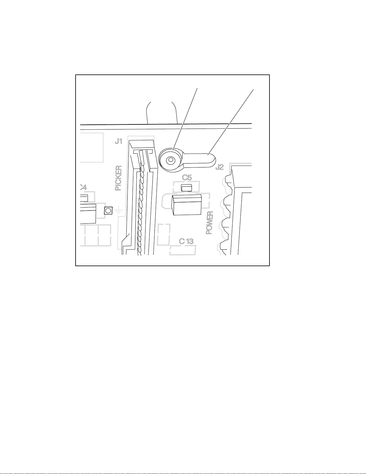
Parts Removal and Replacement 5-7
4. Slide the controller board toward the front ¼-inch along the three guide pins (see Figure 5-
5 and Figure 5-6).
T op Guide Pin
Keyhole
Figure 5-5. Top guide pin and keyhole
cc0076
Page 58

5-8 Compaq StorageWorks SSL2000 Series Library Maintenance and Service Guide
Bottom
Guide Pin
Keyhole
cc0077
Figure 5-6. Bottom guide pin and keyhole
5. Lift the controller board off the guide pins (see Figure 5-7).
Guide Pin
Keyhole
cc0078
Figure 5-7. Removing the controller board
Page 59

To replace the controller board:
6. Place the new board on the three guide pins (see Figure 5-8).
Parts Removal and Replacement 5-9
Guide
Pins
cc0079
Figure 5-8. Replacing the controller board
7. Slide the board toward the rear ¼-inch al ong the pins (see Figure 5-5 and Fi gure 5-6).
8. Make s ure that you seat t he connectors on the back correctly:
a. Two for the motor connector
b. Two for the diagnostic connector
9. Reconnect the following to the controller board:
Note should come AFTER substeps
NOTE: The magazine and front door solenoids are identical. Carefully follow their cables back to ensure
that you make the proper connections.
a. SCSI cable
b. Serial cables for drive 0 (J7) and drive 1 (J6)
c. Magazine solenoid (J14)
d. Magazine opto (J12)
e. Front door solenoid (J11)
f. Front door op t o (J9)
g. Operating panel harness (J4)
10. Replace the power supply as described later in this chapter.
Page 60

5-10 Compaq StorageWorks SSL2000 Series Library Maintenance and Service Guide
Removing and Replacing the Door Solenoid
To remove the door solenoid:
1. Remove the magazine.
2. Remove t he two screws that fasten the door solenoid t o the bracket (see Figure 5-9).
Door
Solenoid
Mounting
Screws
Figure 5-9. Removing the door solenoid
3. Slide out the door solenoid to the power s upply side.
4. Disconnect the door s ol enoid cable from connector J11 on the controller board, and then
remove the door solenoid.
To replace the door solenoid:
5. Position the new solenoid on the mo unting bracket.
6. Tighte n the two screws.
7. Reconnect the solenoid cable to connector J11 on the controller board.
cc0080
Page 61

Removing and Replacing a Tape Drive
To remove a tape drive:
1. Turn off the power to the Library.
2. Unplu g the Library from the power source.
3. Unplug the robotics ribbon cable from the controller board (see Figure 5-10).
4. Remove the brace plate (see Figure 5-10).
Brace Plate
Screws
Robotics
Ribbon
Cable
Parts Removal and Replacement 5-11
cc0081
Figure 5-10. Removing the brace plate
5. Remove t he two upper drive mounting pl ate screws (see Figure 5-11).
cc0021
Figure 5-11. Removing the upper drive mounting plate
6. Lift out the upper drive mounting pl ate (see Figure 5-11).
Page 62

5-12 Compaq StorageWorks SSL2000 Series Library Maintenance and Service Guide
7. Disconnect the power, serial cable, and SCSI connectors from the desired tape drive (see
Figure 5-12).
Power
Cable
Serial
Cable
SCSI
Cable
cc0082
Figure 5-12. Disconnecting the tape drive
8. Lift the tape drive out of the Library chassis (see Figure 5-13).
Figure 5-13. Removing the tape drive
cc0083
Page 63

Parts Removal and Replacement 5-13
9. Remove the four alignment pins for installation on the replacement tape drive (see Figure
5-14).
Upper Alignment Pins
cc0084
Lower Alignment Pins
Figure 5-14. Removing the alignment pins
NOTE: The alignment pin is an assembly made of a plastic spacer (“top hat”) and a screw (see Figure
5-14).
To replace a tape drive:
1. Install the four alignment pins on the replacement tape drive (see Figure 5-14).
2. Lower the new tape dri ve into the Library chassis (see Figure 5-13).
3. Connect the power, serial cable, and SCSI connectors to the drive (see Figure 5-12).
4. Replace the upper drive mounting plate, and tighten the two retaining screws (see Figure
5-11).
5. Replace the brace plate cover (see Figure 5-10).
6. Reconnect the Library to the power source.
7. Turn on the Library and test the operation of the tape drive.
Page 64

5-14 Compaq StorageWorks SSL2000 Series Library Maintenance and Service Guide
Removing and Replacing the Fan Assembly
To remove the fan assembly:
1. Turn off the Library.
2. Unplu g the Library from the power source.
3. Remove the brace plate cover (see Figure 5-10).
4. Remove the power supply as descr ibed later in this chapter.
5. Remove t he four mounting screws on t he fan.
6. Lift the fan out, freeing its cable from the cable clamp.
To replace the fan assembly:
1. Place the new fan in the Library with fan flow down as indicated by the arrows molded
into the fan housing (see Figure 5-15).
2. Place the fan cable under the cable clamp.
3. Tighte n the four screw s on the fan.
Figure 5-15. Replacing the fan assembly
4. Replace the power supply as described later in this chapter.
5. Replace the brace plate cover (see Figure 5-10).
cc0085
Page 65

Removing and Replacing the Front Panel
To remove the front panel:
1. Remove the outside cover from the Library (see Appendix C).
2. Remove t he six screws tha t secure the front panel to the Libr ary chassis (se e Figure 5-16).
Front Panel
Attachment Screws
Parts Removal and Replacement 5-15
Figure 5-16. Front panel attachment screw locations
3. Pull the front panel forw ard and away from the Librar y chassis.
cc0086
Page 66

5-16 Compaq StorageWorks SSL2000 Series Library Maintenance and Service Guide
4. Disconnect the front panel cable (see Figure 5-17).
Front Panel
Cable
cc0087
Figure 5-17. Disconnecting the front panel cable
5. Disconnect the door opto sensor from connector J9 on the controller board.
6. Pull the door opto sensor cable throug h the cable cutout in the Library chassis.
To replace the front panel:
1. Push the door opto sensor cable through the cable cutout in the Library chassis.
2. Reconnect the front panel cable.
3. Recon nect the door opto sensor to connector J9 on the controller board.
4. Place the front panel on the front of the Library and then push it into place.
5. Tighten the six screws f rom inside the Library chassis (see Figure 5-16).
Removing and Replacing the Magazine Guide
To remove the magazine guide:
1. Remove the brace plate (see Figure 5-10).
2. Remove the uppe r dr ive mou nti ng pl ate (see Fig ure 5-1 1).
3. Remove the tape drive(s) as described earlier in this chapter.
Page 67

Parts Removal and Replacement 5-17
4. Remove the four hex sta ndoffs that secure the bottom drive mounting plate to the L ibrary
chassis (see Figure 5-18).
5. Lift the bottom drive mounting plate away from the Library chassis (see Figure 5-18).
Hex Standoffs
cc0088
Figure 5-18. Removing the bottom drive mounting plate
6. Remove the nine screws that secure the magazine guide to the Library chassis (see Figure
5-19).
Magazine
Guide
Screws
cc0089
Figure 5-19. Magazine guide screw locations
Page 68

5-18 Compaq StorageWorks SSL2000 Series Library Maintenance and Service Guide
7. Lift the magazine guide out through the front door (see Figure 5-20).
cc0090
Figure 5-20. Removing the magazine guide
To replace the magazine guide:
1. Place the new magazine guide into the Library (see Figure 5-20).
2. Tighten the nine screws on the magazi ne guide (see Figure 5-19).
3. Replace the bottom drive mounting plate (see Figure 5-18).
4. After adding Loctite, install and fully tighten the four hex standoffs (see Figure 5-18).
5. Replace the tape drive(s) as described earlier in this chapter.
6. Replace the top drive mounting plate (see Figure 5-11).
7. Replace the brace plate cover (Figure 5-10).
Page 69

Removing and Replacing the Magazine Latch Solenoid
To remove the magazine latch solenoid:
1. Remove the magazine.
2. Remove t he two screws that secure the ma gazine latch cover to the Library chassis (see
Figure 5-21).
3. Remove the magazine l atch cover.
Magazine
Latch Cover
Screws
Parts Removal and Replacement 5-19
Figure 5-21. Removing the magazine latch cover
cc0091
Page 70

5-20 Compaq StorageWorks SSL2000 Series Library Maintenance and Service Guide
4. Remove t he two screws that secure the magazine latch solenoid to its mounting bracket
(see Figure 5-22).
Magazine Latch Solenoid
Mounting Screws
cc0092
Figure 5-22. Magazine latch solenoid mounting bracket screw locations
5. Push the detached solenoid back through the ope ning into the p ower supply compartment.
6. Disconnect the cable at connector J14 on the controller board, and then remove the
magazine latch solenoid.
To replace the magazine latch solenoid:
1. Position the magazine l atch solenoi d through the opening in the L i brary chassis toward the
magazine compartment.
2. Tighte n the two screws that attach the solenoid to it s mounting bracket (see Figure 5-22).
3. Replace the magazine latch cover (see Figure 5-21).
4. Connect the cable at connector J14 on the controller board.
Removing and Replacing the Pow er Supply Assembly
To remove the power suppl y:
1. Turn off the Library.
2. Unplu g the Library from the power source.
3. Remove t he Library outs ide cover. If ne cessary, see Figur e C-4 or Figure C-5.
4. Remove the brace plate cover (see Figure 5-10).
Page 71

Parts Removal and Replacement 5-21
5. Disconnect the picker ribbon cable from connector J1 on the controller board (see Figure
5-23).
Picker Ribbon
Cable
Ferrite
Controller Board
Connector
cc0093
Figure 5-23. Disconnecting the picker ribbon cable
6. Bend the tabs back that hold the picker ribbon cable in place (see Figure 5-24).
Tabs
Figure 5-24. Picker ribbon cable tabs
cc0094
Page 72

5-22 Compaq StorageWorks SSL2000 Series Library Maintenance and Service Guide
7. Gently roll the brace plate cover and ribbon cable assembly over and safely out of the way
(see Figure 5-25).
cc0095
Figure 5-25. Turning the base plate
8. Unplug the power cable from the power supply (see Figure 5-26).
cc0096
Figure 5-26. Unplugging the power supply
Page 73

Parts Removal and Replacement 5-23
9. On the magazine side, remove the two screws that secure the power supply to the Library
chassis (see Figure 5-27).
Retaining Screws
Figure 5-27. Power supply retaining screws
cc0097
Page 74

5-24 Compaq StorageWorks SSL2000 Series Library Maintenance and Service Guide
10. Disconnect the following from the power supply (see Figure 5-28):
a. Controller board (at connector J2)
b. Fan
c. Drive power harness
Controller
Board
Connector
Fan
Connector
Drive Power
Harness
Connector
cc0098
Figure 5-28. Disconnecting the controller board, fan, and drive power harness
Page 75

11. Disconnect the wires to the power switch (see Figure 5-29).
Power
Switch
Terminals
Parts Removal and Replacement 5-25
Ground Lug
Figure 5-29. Disconnecting the power switch wires
NOTE: Pull on the spade terminal connector, not on the wire itself.
12. Disconnect the ground lug.
cc0099
Page 76

5-26 Compaq StorageWorks SSL2000 Series Library Maintenance and Service Guide
13. Lift out the power supply a ssembly out and then lay it on the magazine side, being car eful
not to bump the shuttle mechanism (see Figure 5-30).
cc0100
Figure 5-30. Removing the power supply
To replace the power supply:
1. Place the power supply in the Library chassis (see Figure 5-30).
2. Connect the wires from the power supply to the power switch (see Figure 5-29).
3. Connect the following to the power supply (see Figure 5-28):
a. Board (J2)
b. Fan
c. Drive power harness
4. Using two screws, secure the power supply to the Library chassis (see Figure 5-27).
5. Reconnect the power cable to the power supply (see Figure 5-31).
Brown
Black
Blue
White
cc0101
Figure 5-31. Connecting the power cable to the power supply
Page 77

6. Replace the brace plate (see Figure 5-10).
7. Connect the Library to the AC power source.
8. Turn on the Library.
Removing and Replacing the Power Switch
To remove the power switch:
1. Unplu g the Library from the power source.
2. Remove the power supply as described earlier in this chapter.
3. Remove t he front panel as described ea rlier in this chapter.
4. Locate the power switch at the lower right of the Library chassis front, and then remove its
two retainin g screws (see Figure 5-32).
Parts Removal and Replacement 5-27
cc0102
Figure 5-32. Power switch retaining screws
5. Lift out the power switch.
To replace the power switch:
1. Positi on the power switch through the front of the Libr ary chassis.
2. Replace the two retaining screws in front.
3. Replace the front panel as described earlier in this chapter.
4. Replace the power supply as described earlier in this chapter.
Page 78

5-28 Compaq StorageWorks SSL2000 Series Library Maintenance and Service Guide
Removing and Replacing the Shuttle Mechanism
To remove the shuttle mechanism:
1. Open the magazine door to the Library.
2. Remove the magazine from the Library.
3. Turn off the power to the Library.
4. Press down on the tab to release the shuttle mechanism cable clamp (see Figure 5-33).
Cable
Support
Plate
Cable
Release
Lever
Access
Hole
Figure 5-33. Cable clamp tab location
cc0103
Page 79
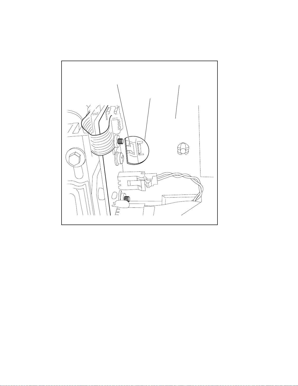
Parts Removal and Replacement 5-29
5. Push in on the cable release lever, accessed through the hole in the cable support plate (see
Figure 5-34).
Cable
Release
Lever
Cable
Support
Plate
Access
Hole
Figure 5-34. Cable release lever
cc0104
Page 80

5-30 Compaq StorageWorks SSL2000 Series Library Maintenance and Service Guide
6. Remove the shuttle mechanism cable.
7. Pushing only from the base, move the s huttle mechanism back half way (see Figure 5-35).
Figure 5-35. Pushing the shuttle mechanism
CAUTION: Never move the shuttle by pushing on the top of the mechanism.
cc0105
Page 81

Parts Removal and Replacement 5-31
8. Remove the screw that holds down the guide bar, using a 3 mm Allen wrench (see Figure
5-36 and Figure 5-37).
NOTE: You can also remove the screw through the access hole using a 3 mm hex driver.
Guide
Bar
Screw
Figure 5-36. Removing the guide bar screw
cc0106
Page 82

5-32 Compaq StorageWorks SSL2000 Series Library Maintenance and Service Guide
cc0107
Access Guide Bar Screw
Through the Top
Figure 5-37. Accessing the guide bar screw
9. Lift the shuttle mec hanism up, sliding the fron t off of the guide pin and moving it forward
to release it from the anti-rotation bracket (see Figure 5-39 and Figure 5-40).
cc0108
Guide
Bar
Pin
Figure 5-38. Lifting the shuttle mechanism
Page 83

Anti-Rotation
Bracket
Parts Removal and Replacement 5-33
cc0109
Figure 5-39. Anti-rotation bracket location
10. Lift the shuttle mechanism out through the top of the Li brary chassis (s ee Figure 5-40).
cc0110
Figure 5-40. Removing the shuttle mechanism
Page 84

5-34 Compaq StorageWorks SSL2000 Series Library Maintenance and Service Guide
To replace the shuttle mechanism:
1. Place the new shuttle mechanism in the AIT Library chassis, moving it back to engage the
anti-rotati on bracket and sliding it onto the pin (see Figure 5-40 and Fi gure 5-39).
2. Tighten the screw that holds down the guide bar (see Figure 5-36 and Figure 5-37).
3. Move the shuttle mechanism forward, push ing from the base. Do not push on the top of
the mechanism (see Figure 5-35).
4. Reconnect the shuttle mechanism cable (see Figure 5-34).
5. Tighten the tab on the shuttle mechanism cable (see Figure 5-33).
6. Replace the magazine.
7. Close the magazine door.
8. Turn on the Library.
Page 85

Removing and Replacing a PT M
To remove a PTM :
1. Disconnect AC power from the Library units.
2. Loosen the screws that secure the Library unit’s mounting ears to the front of the storage
cabinet.
3. Loosen the rear slide screws so that the Library units float freely in the storage cabinet.
4. Unplug the motor control cable from the PTM motor housi ng assembly (see Figure 5-41).
5. If the master unit (top) is to be removed for service, disconnect the motor cable an d plug it
into the unit directly below it (slave 0). Reconfigure slave 0 to be the master unit and slave
1 to be slave 0, slave 2 to be slave 1, and so forth (s ee Figure 5-41) .
NOTE: After installation, there are software ramifications in changing a Library’s configuration and
should only be done if necessary.
6. Disconnect the RJ45 ca ble from the unit to be removed or serviced an d then plug it into
the next unit so all units remain in series.
Parts Removal and Replacement 5-35
cc0032
Figure 5-41. Unplugging the PTM motor housing assembly control cable
Page 86

5-36 Compaq StorageWorks SSL2000 Series Library Maintenance and Service Guide
7. Remove the bullet-nose thumb scr ews and washers (two per unit) that secure the PTM to
the Library units (see Figure 5-42).
Thumbscrews
and Washers
cc0113
Figure 5-42. Removing the PTM
8. Gently pull the PTM out and away from the Library units (see Figure 5-42) .
Page 87

Parts Removal and Replacement 5-37
To replace a PTM:
1. Holding the PTM upright, position it against the rear panels so that the PTM motor
housing assembly slides into the available space and the two pilot pins on the extrusion
mate with the holes in the rea r of the top Libra ry unit (see Fig ure 5-43).
PTM Motor
Housing
Assembly
Extrusion
Mating
Hole
Pilot
Pin
Pilot
Pin
Figure 5-43. Installing the PTM
cc0111
Page 88

5-38 Compaq StorageWorks SSL2000 Series Library Maintenance and Service Guide
2. Attach the PTM to the master (top) unit using two bulle t-nose thumbscr ews and washers
through the top two holes in the extrusion (see Figure 5-44). Do not fully tighten the
thumbscrews at this time.
Thumbscrews
and Washers
cc0112
Figure 5-44. Securing the PTM to the master unit
3. Align the two holes on the extrusion wi th mounting holes on the slave unit and attach the
PTM in place using two bullet-nose thumbscrews and washers (Figure 5-42). Do not fully
tighten the thumbscrews at this time.
NOTE: If a screw hole is offset, push the slave unit slightly forward to make a gap between it and the
channel.
4. Repeat Steps 2 through 4 for each additional slave unit. Do not fully tighten the
thumbscrews at this time.
5. Tighten all rear storage cabinet slide screws.
6. Tighten all PTM thumbscrews.
7. Tighte n all screws that secure the Libr ary unit’s mounting ears to the f ront of the storage
cabinet.
8. Attach all power and communication cables.
Page 89

Introduction
This appendix lists the following specifications and regulatory requirement s me t by the Compaq
StorageWork s SSL2000 Series Library (AIT Libra ry):
■ Specifications:
G Operational performance
G Reliability
G Power
Appendix A
Specifications
G Mechanical
G Environmental
G Acoustic emission
■ Regulatory requirements:
G Safety
G Electromagnetic Emission (EM)
G FCC and VCCI
Page 90

A-2 Compaq StorageWorks SSL2000 Series Library Maintenance and Service Guide
Table A-1
Operational Performance Specifications
Description Specification
Host Interface Fast Wide SCSI (differential)
Low Voltage Differential (LVD)
Number of cartridges, full magazine 19
Media type AIT 8 mm, Advanced Metal Evaporated
Number of drives 1 or 2
Load time 15 sec (max), including picking from slot
Unload time 15 sec (max), including returning to slot
Rewind speed 160 in/sec
Sustained native data transfer rate, maximum 21.6 to 43.2 GB/hr
Native data capacity (full magazine) 950 GB
Compressed data capacity (2:1, full magazine) 1900 GB
Page 91

Table A-2
Reliability Specifications (Drives)
Description Specification
Data error rate (recoverable) 1 in 10
MTBF 250,000 hr @ 30% duty cycle
MTTR 30 min
Head life 50,000 tape motion hrs
17
bytes
Table A-3
Reliability Specifications (Library System Robotics)
Description Specification
Life expectancy, load/unload operations 1,000,000 cycles
Design life 7 yrs
Specifications A-3
Table A-4
Power Specifications
Description Specification
Voltage 115 to 240 VAC
Current 1.5 to 1.2 A
Line frequency 47 to 63 Hz
Page 92

A-4 Compaq StorageWorks SSL2000 Series Library Maintenance and Service Guide
Table A-5
Mechanical Specifications (Tabletop Model)
Description Specification
Height 7.9 in (20 cm)
Width 17.3 in (44 cm)
Depth:
Overall
Behind panel
Weight:
Single drive
Dual drive
24 in (61 cm)
22.75 in (57.79 cm)
41 lbs (18.6 kg)
41.5 lbs (18.8 kg)
Table A-6
Mechanical Specifications (Rackmount Model)
Description Specification
Height 6.7 in (17 cm)
Width 17.3 in (44 cm)
Depth:
Overall
Behind panel
Weight:
Single drive
Dual drive
24 in (61 cm)
22.75 in (57.79 cm)
41 lbs (18.6 kg)
41.5 lbs (18.8 kg)
Page 93

Table A-7
Environmental Specifications (Operating)
Description Specification
Specifications A-5
Dry bulb temperature
Temperature gradient
Temperature shock
Wet bulb temperature
Relative humidity (non-condensing) 15% to 85%
Humidity gradient 10%/hr
Altitude -100 ft to +10,000 ft (-305 m to 3050 m)
50°F to 104°F (10°C to 40°C)
1.8°F/min (1°C/min)
27°F (15°C) over 2 min
78.8°F (26°C)
Table A-8
Environmental Specifications (Packed or Unpacked)
Description Specification
Dry bulb temperature
Temperature gradient
Temperature shock
Wet bulb temperature
Relative humidity (non-condensing) 10% to 95%
Humidity gradient 10%/hr
-40°F to 140°F (-40°C to 60°C)
36°F (20°C)/hr (across the range)
27°F (15°C) (over 2 min)
86°F (30°C)
Altitude -100 ft to +10,000 ft (-305 m to 3050 m)
Page 94

A-6 Compaq StorageWorks SSL2000 Series Library Maintenance and Service Guide
Table A-9
Environmental Specifications (Storage/Transit)
Description Specification
Dry bulb temperature
Temperature gradient
Temperature shock
Wet bulb temperature
Relative humidity (non-condensing) 5% to 95%
Humidity gradient 10%/hr
Altitude (sea level) -100 ft to +10,000 ft (-305 m to 3050 m)
-40°F to 140°F (-40°C to 60°C)
45°F (25°C)/hr (across the range)
27°F (15°C) (over 2 min)
86°F (30°C)
Table A-10
Acoustic Emission Level
Drive Condition Emission Level
Drive in use
(Intermittent robot motion excepted)
<50 dBA
Page 95

Safety
The Library carries the following Regulatory Agency product safety certifications.
Regulator Agency Product Safety Certifications
Description Specification
Certification Standard
UL Listed UL 1950
TUV/Product Service EN 60 950
GS Mark
CE Mark EMC Directive, Low Voltage Directive
Canadian UL Listed CSA 22.2 No. 950
Electromagnetic Emission (EM)
Specifications A-7
Table A-11
Notice
This equipment has been tested using double shielded cabl es for EM compliance. The use of
unshielded cables or modifications requires system testing for EMI testing for compliance to the
standard.
Industry Canada
This Class A digital apparatus meets all requirem ents of the Canadian Interference-causing
equipment regulations.
Industrie Canada
Cet appareil numérique de la classe A respecte toutes les exigencies du Règlement sur le
matériel brouilleur du Canada.
Page 96

A-8 Compaq StorageWorks SSL2000 Series Library Maintenance and Service Guide
FCC Notice
This equipment has been tested and found to comply with the limits for a Class A digital device,
pursuant to Part 15 of the FCC rules. These limits are designed to provide reasonable protection
against harmful interference when the equipment is operated in a commercial environment. This
equipment generates, use s and can radiate radio frequency energy and, i f not installed and used
in accordance with the instruction manual, may cause harmful interference to radio
communications. Operation of this equipment in a residential area is likely to cause harmful
interference in which case the user will be required to correct the interference at their own
expense.
Table A-12
Acoustic Noise Declaration Declared per ISO 9296 and ISO 7779
Sound Power Level L
Product Idle Operate Idle Operate
SSL2000 Series
Library
NOTE: Current values for specific configurations are available from Compaq representatives 1 B = 10
dBA.
6.4 7.0 48 48
B Sound Pressure Level L
W Ad,
(bystander position)
pAm,
dBA
Table A-13
Schallemissionswerte - Werteangaben nach ISO 9296 und ISO 7779 /DIN
EN27779
Schalleistungspegel L
Gerät Leerlauf Betrieb Leerlauf Betrieb
SSL2000 Series
Library
NOTE: Aktuelle Werte für spezielle Ausrüstungsstufen sind über die Compaq Vertretungen erhältlich. 1 B
= 10 dBA.
6,4 7,0 48 48
B Schalldruckpege L
W Ad,
(Bediener position)
pAm,
dBA
Page 97

FCC and VCCI Requirements
The following FCC and VCCI not i ces apply to the Library.
Statement for Equipment Meeting FCC Class A Requirements
This equipment has been tested and found to comply with the limits for a Class A digital device,
pursuant to Part 15 of the FCC rules. Operatio n i s subject to the following two conditions: (1)
This device may not cause harmful interference and (2) This device must accept any
interference that may cause undesirable operation.
This equipment generates, uses, and can radiate radio frequency energy and, if not installed and
used in accordance with the instructions, may cause harm ful interfere nce to radio
communications. However, there is no guarantee that interference will not occur in a particular
installation. If this equi pment does cause harmful inte rference to radio or television reception,
which can be determined by turning the equipment off and on, the user is encouraged to try to
correct the interference by one or more of the following measures:
1. Reorient or relocate the receiving antenna.
2. Increase the separation between the equipment and receiver.
3. Connect the equipment into an outlet on a circuit different from that to which the receiver
is connected.
Specifications A-9
4. Consult the dealer or an experienced radio/TV technician for help.
Page 98

A-10 Compaq StorageWorks SSL2000 Series Library Maintenance and Service Guide
Equipment Meeting VDE Class B Requirements (VFG 1046/84 and VFG 243/91 for Germany)
Für Bundesre publik Deutschla nd
For Federal Republic of Germ any
Pour la Républ ique féderal d’Allemagne
Bescheinigu ng de s Hers te lle r s/I m por te ur s
Dieses Gerät ist Übereinstimmung mit den Bestimmungen der BMPT Vf g. 243/1991 und V fg.
46/1992 in Verbindung mi t EN55022:1987 (DIN VDE 0 878-3:11.89) oder Vfg. 1046/1984 mit
Vfg. 483/1986, funkentstört. Es trägt als Nachweis der EMV-Konformität entweder eine
Konformitätskennzeichnung oder das freiwillige VDE-Funkschutzzeichen.
Der vorschriftsmäßige Betrieb mancher Geräte (z.B. M eßsender) kann a llerdings gewissen
Einschränkungen unterliegen. Beachten Sie deshalb die unten aufgeführten Hinweise.
Für Geräte die nicht mit dem VDE-Funkschut zzeichen versehen sind wurde dem Bundesamt für
Zulassungen in der Telekommunikation (BZT) des Inverkehrbringen dieses Gerätes angezeigt
und die Berechtigung Zur Überprüfung der Serie auf Ein haltung der Besti mmungen ei ngeräumt.
Betreiberhinweis
Wir sind verpf l ichtet, Sie auf folgende Fakten hinzuweisen (BMPT-Amtsblattverfügung 243/91
bzw. 1046/84 §2, Abschnitt 5):
Dieses Gerät wurde funktechnisch sorgfältig entstört und geprüft. Wird deises Gerät innerhal b
einer Anlage zusammen mit a nderen Gerät en betriebe n, muß bei Inans pruchnahme der
“Allgemeinen Betriebsge nehmigung” na ch BMPT-AmtsblVfg. 243/91 bzw. 1046/84 die
gesamte Anlage den unter §2, Abschnitt 1, genannten Voraussetzungen entsprechen.
Externe Datenkabel:
Sollte ein Austausch der von Digital spezifizierten Datenkabel nötig werden, muß der Betriber
für eine einwandfreie Funkentstörung sicherstellen, daß Austauschkabel im Aufbau und
Abschirmqualität dem Compaq Originalkabel entsprechen.
Page 99

VCCI Notice for Japan Class I Equipment
Japanese Voluntary Control Council for Interference (VCCI).
This equipment is in the 1st Class category (informatio n equipment to be used in commercial
and/or industrial areas) and conforms to the standards set by the Voluntary Control Council for
Interference by Information Technology Equipment aimed at preventing radio interference in
commercial and/or industrial areas.
Consequently, when used in a residential area or in an area adjacent thereto, radio interference
may be caused to radios and TV receivers, and so on. Read the instructions for correct handling.
Specifications A-11
Page 100

Introduction
This appendix lists the FRUs, spares, and accessories that are available for the Compaq
StorageWorks SSL2000 Series Library.
Description Part Number
Appendix B
FRUs, Spares, and Accessories
Table B-1
FRUs, Spares, and Accessories
SPS-DRV, 50 GB, AIT, Library 192988-001
SPS-BD with Shuttle 180751-001
SPS-BD, LVD/SE Control 180752-001
SPS-Panel, Front, with Control Panel 180753-001
SPS-Switch, Power 180754-001
SPS-Receptacle, AC 180755-001
SPS-CA, Motor Flex 6 Conductor 180756-001
SPS-CA, Motor Flex Tach 6 Conductor 180757-001
SPS-CA, Shuttle Flex 30 Conductor 180758-001
SPS-Switch, Door Sensor 180759-001
SPS-CA, Serial Harness 180760-001
SPS-CA, SCSI Control0 Drive LVD 180761-001
SPS-CA, SCSI Control1 Drive LVD 180762-001
SPS-CA, Split Power Harness 180763-001
SPS-CA, 15-inch Opto Sensor Harness 180764-001
continued
 Loading...