

Page 1

HP 1X4 Server Console Switch User Guide
Part Number 442232-001
November 2006 (First Edition)
Page 2

© Copyright 2006 Hewlett-Packard Development Company, L.P.
The information contained herein is subject to change without notice. The only warranties for HP products and services are set forth in the express
warranty statements accompanying such products and services. Nothing herein should be construed as constituting an additional warranty. HP
shall not be liable for technical or editorial errors or omissions contained herein.
Page 3

Contents
Overview..................................................................................................................................... 5
HP 1X4 Server Console Switch.................................................................................................................... 5
Component identification............................................................................................................... 6
Front and rear panel components ................................................................................................................6
Installing the console switch ........................................................................................................... 7
Precautions............................................................................................................................................... 7
Rack mounting precautions ............................................................................................................... 7
0U, side-mount installation.......................................................................................................................... 8
1U installation .......................................................................................................................................... 8
Connecting peripherals..............................................................................................................................9
Connecting computers ............................................................................................................................... 9
Powering up the console switch................................................................................................................... 9
Resetting the console switch...................................................................................................................... 10
Operating the console switch ....................................................................................................... 11
Autoscanning.......................................................................................................................................... 11
FLASH upgrading.................................................................................................................................... 11
Connecting USB peripheral devices...........................................................................................................11
Controlling PC and hub ports.................................................................................................................... 11
Using LEDs/switches and hot keys.............................................................................................................11
Commands ................................................................................................................................ 13
Keystroke commands ............................................................................................................................... 13
Local port commands ..................................................................................................................... 13
Hub commands............................................................................................................................. 14
Scan mode commands ...................................................................................................................14
Mouse restore commands ...............................................................................................................15
Activation sequence commands....................................................................................................... 15
Regulatory compliance notices ..................................................................................................... 16
Regulatory compliance identification numbers............................................................................................. 16
Federal Communications Commission notice............................................................................................... 16
FCC rating label............................................................................................................................ 16
Class A equipment......................................................................................................................... 16
Class B equipment......................................................................................................................... 17
Declaration of conformity for products marked with the FCC logo, United States only....................................... 17
Modifications.......................................................................................................................................... 17
Cables................................................................................................................................................... 18
Canadian notice (Avis Canadien).............................................................................................................. 18
European Union regulatory notice .............................................................................................................18
Disposal of waste equipment by users in private households in the European Union......................................... 19
Japanese notice ...................................................................................................................................... 19
Korean notice ......................................................................................................................................... 19
BSMI notice............................................................................................................................................ 20
Power cord statement for Japan................................................................................................................. 20
Contents 3
Page 4

Acronyms and abbreviations........................................................................................................ 21
Contents 4
Page 5

Overview
In this section
HP 1X4 Server Console Switch .................................................................................................................. 5
HP 1X4 Server Console Switch
The HP 1X4 Server Console Switch supports four target computers and one local user. With its rear panel
keyboard, video and mouse ports, combined with a front panel USB 2.0 hub, the console switch can be
accessed from a single keyboard, mouse, and monitor console. Keyboard and mouse data is transferred
to the computers using a USB connection, or via PS/2 connection. When using a USB connection, the
three-port USB hub allows one computer at a time to access connected peripherals. The console switch is
hot-pluggable which allows components to be removed or added without shutting down the unit.
Overview 5
Page 6
Component identification
In this section
Front and rear panel components............................................................................................................... 6
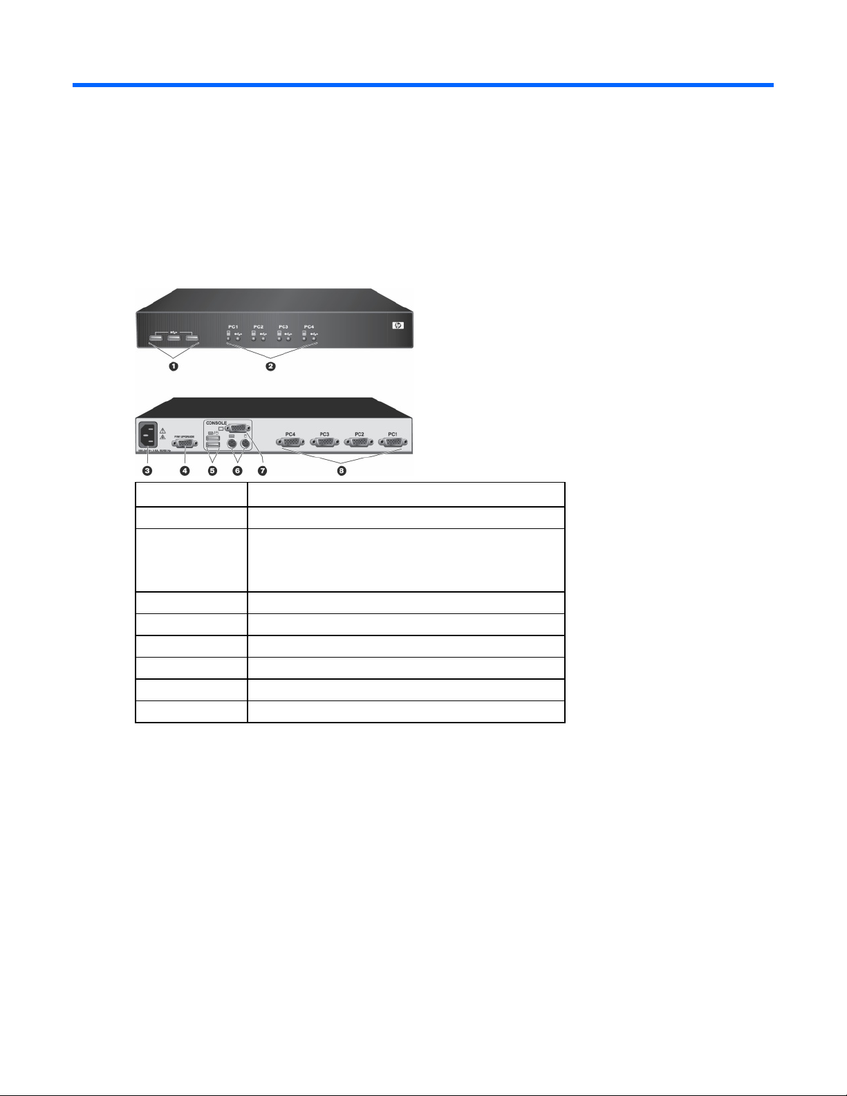
Front and rear panel components
Item Description
1 USB 2.0 hub
2 Port selection switches/LEDs:
• KVM—green
• USB hub—yellow
3 Power receptacle
4 Firmware upgrade port
5 USB ports
6 PS/2 ports
7 Monitor connection
8 CPU ports 1-4
Component identification 6
Page 7
Installing the console switch
In this section
Precautions.............................................................................................................................................. 7
0U, side-mount installation......................................................................................................................... 8
1U installation ......................................................................................................................................... 8
Connecting peripherals............................................................................................................................. 9
Connecting computers .............................................................................................................................. 9
Powering up the console switch ................................................................................................................. 9
Resetting the console switch..................................................................................................................... 10
Precautions
This symbol indicates the presence of hazardous energy circuits or electric shock
The AC inlet is in the main disconnect.
WARNING: Text set off in this manner indicates that failure to follow directions in the warning could
result in bodily harm or loss of life.
WARNING: To reduce the risk of electric shock or damage to the equipment:
• Disconnect power from the system by unplugging all power cords from the power supplies.
• Do not disable the power cord grounding plug. The grounding plug is an important safety
feature.
• Plug the power cord into a grounded (earthed) electrical outlet that is easily accessible at all
times.
Rack mounting precautions
WARNING: Mounting of the equipment in the rack should be such that a hazardous condition is not
achieved due to uneven mechanical loading.
hazards. Refer all servicing to qualified personnel.
WARNING: To reduce the risk of injury from electric shock hazards, do not open this
enclosure. Refer all maintenance, upgrades, and servicing to qualified personnel.
IMPORTANT: Installation of the equipment in a rack should be such that the amount of airflow
required for safe operation of the equipment is not compromised.
IMPORTANT: If installed in a closed rack assembly, the operation temperature of the rack
environment might be greater than room ambient. Use care not to exceed the rated maximum
operating temperature of 40° C for this product.
IMPORTANT: Consideration should be given to the connection of the equipment to the supply circuit
and the effect that overloading of circuits might have on overcurrent protection and supply wiring.
Consider equipment nameplate ratings for maximum current.
Installing the console switch 7
Page 8

IMPORTANT: Reliable grounding of rack mounted equipment should be maintained. Pay particular
attention to supply connections other than direct connections to the branch circuit (for example, use
of power strips).
0U, side-mount installation
1. Line up the holes in the rack mounting brackets with the holes on the side of the console switch.
2. Attach the 0U brackets to one side of the switch using two of the four applicable screws provided.
3. Install two cage nuts into the bracket.
4. Secure the console switch to the rails of the rack using the approved method of the rack
manufacturer.
1U installation
NOTE: The console switch is front and rear mountable. Use the two pre-drilled holes closer to the
front panel for front rack mounting, or use the two holes closer to the rear panel for the rear rack
mounting.
1. Line up the holes in the rack mounting brackets with the holes on the side of the console switch.
2. Attach the 1U brackets to the console switch using two of the four screws provided on each side of
the console switch.
3. Install one cage nut on each side of the rack.
Installing the console switch 8
Page 9

Secure the console switch to the rails of the rack using the approved method of the rack
4.
manufacturer.
Connecting peripherals
NOTE: HP recommends using only the HP 1X4 KVM Console 6-foot PS/2 cable (AF612A) and HP
1X4 KVM USB cable (AF613A) for connecting peripherals.
Connect the shared PS/2 or USB keyboard, monitor and mouse, as well as other USB devices to the
console switch. If connecting PS/2 computers, use the 3-in-1 keyboard, monitor and mouse cable. If
connecting USB computers, use the USB cable and separate VGA cable
Connecting computers
Connect each computer to the console switch via the rear panel CPU ports labeled PC1 through PC4.
Powering up the console switch
1. Connect to AC power.
2. Power up the connected computers, ensuring that the keyboard and mouse are enabled.
The console switch features the following LED indicators:
• Green (KVM):
o Off—No device connected.
o On (Constant)—Target device is connected but not selected.
o On (Flashing)—Target device is connected and selected.
• Yellow (Hub):
o Off—No device connected.
o On (Constant)—Target device is connected but not selected.
o On (Slow flashing 1Hz)—Target device is connected and selected.
o On (Fast flashing 10Hz)—Target device is disconnected and pending.
Installing the console switch 9
Page 10

NOTE: When the USB hub is switched, 10 seconds will elapse before reconnecting to the selected
port. During that time, the yellow LED will flash quickly. Once the USB hub reconnects, the yellow
LED flashes slowly.
Resetting the console switch
The console switch features an LED test option and a reset feature.
To test the LEDs, press and hold the first and last LEDs/switches for two seconds. After two seconds, all
LEDs illuminate. Press each switch to turn off the respective LED. When all switches have been pressed,
the console switch returns to normal operation.
To reset the console switch to the default settings, press the LEDs/switches for five seconds. After five
seconds, all LEDs flash rapidly and then turn off while the console switch resets.
Installing the console switch 10
Page 11

Operating the console switch
In this section
Autoscanning......................................................................................................................................... 11
FLASH upgrading................................................................................................................................... 11
Connecting USB peripheral devices.......................................................................................................... 11
Controlling PC and hub ports................................................................................................................... 11
Using LEDs/switches and hot keys............................................................................................................ 11
Autoscanning
Autoscanning allows scanning or monitoring of each target computer in the system at regular intervals
without having to switch from port to port manually.
To enable autoscanning, see "Scan Mode commands (on page 14)."
FLASH upgrading
Flash upgrading is supported via the female DB-9 serial port connection on the rear panel.
During firmware upgrades, the console switch is not functional. However, the unit's "Keep Alive" feature
prevents the target devices from sensing a keyboard or mouse loss.
Connecting USB peripheral devices
The console switch features three USB Type A ports on the front panel to enable USB peripheral device
connection. Once connected, these USB peripheral devices can be accessed by up to four of the attached
computers. Using a hot key command, you can bind or unbind peripheral sharing to the target computer
selection.
NOTE: Use either hot key commands or the LEDs/switches to select the target computer for
peripheral device connection. Only one target computer can be selected at a time for connection to
the shared peripheral devices.
Controlling PC and hub ports
There are two ways to control the console switch for PC and hub ports:
• Front panel LEDs/switches
• Keystroke command sequence
Using LEDs/switches and hot keys
• Using the LEDs/switches provides direct control over console switch operation and port switching.
The PC LEDs/switches control PC port switching, and the USB LEDs/switches control USB hub port
switching.
Operating the console switch 11
Page 12

• Using the hot keys provides an extensive and easy-to-use method of controlling and configuring the
KVM installation from the console keyboard. Hot keys provide asynchronous switching of the KVM
focus and USB peripherals.
For more information about hot key functions, see "Keystroke commands (on page 13)."
Operating the console switch 12
Page 13

Commands
In this section
Keystroke commands .............................................................................................................................. 13
Keystroke commands
The CRTL+CRTL+COMMAND hot key sequence activates command modes that are used to select PCs,
release PCs, or set interval scan times.
NOTE: Ctrl+Ctrl is the default activation key stroke. To change the activation key stroke, see
"Activation sequence."
When activating command mode, the second activation key (<CTRL>) must be pressed within one second
of the release of the first activation key (<CTRL>).
Command mode is exited by pressing the <ENTER> key to accept the action, or the <ESC> key, which
aborts the requested action.
While in command mode, mouse activity is not passed to the target computer. However, the activation
keys are passed to the target computer.
The key commands that are supported in the console switch are defined in the following table. The
commands are not case sensitive.
Local port commands
Keysroke Value Action
<CTRL><CTRL>x<ENTER> x = 1-4 Selects active KVM target .
<CTRL><CTRL>L<BACKSP>
[<BACKSP>…]<TERM>
Toggles between current and previous active
port.
Port selection changes every time <BACKSP>
is pressed and released.
The video session is active immediately, but
command mode must be exited for mouse
movement and keystrokes to be passed to the
target.
<TERM>: Either <ENTER> or <ESC> can be
pressed to exit command mode.
Commands 13
Page 14

Keysroke Value Action
<CTRL><CTRL>L<x ARROW>
[<x ARROW>…]<TERM>
x = UP, DOWN, RIGHT or
LEFT
UP and RIGHT ARROW selects the next higher
numbered port.
DOWN and LEFT ARROW selects the next
lower numbered port.
Port selection changes every time the arrow
key is pressed and released.
The video session is active immediately, but
command mode must be exited for mouse
movement and keystrokes to be passed to the
target.
<TERM>: Either <ENTER> or <ESC> may be
pressed to exit command mode.
Hub commands
Key sequence Value Action
<CTRL><CTRL><Fx><ENTER> x = 1-4
<CTRL><CTRL><F9><ENTER>
<CTRL><CTRL><F10><ENTER>
<CTRL><CTRL>Bx<ENTER> x = "-" (minus key)
Scan mode commands
Key sequence Value Action
<CTRL><CTRL>Snn<ENTER> nn = 2-60
(seconds)
<CTRL><CTRL>SG<ENTER>
<CTRL><CTRL>SH<ENTER>
<CTRL><CTRL>SMx<ENTER> x = "-" (minus key)
x = "+" (plus key)
x = "+" (plus key)
Sets the interval scan time.
Default setting is 30 seconds.
Starts the Interval Scan function.
Initiation of this command automatically disables
PC/USB hub port binding.
Halts the Interval Scan function.
Enables (plus key) mouse movement to halt scanning or
Disables (minus key) mouse movement to halt scanning.
Selects which PC target is in control of USB hub
ports.
Initiation of this command automatically disables
PC/USB hub port binding.
(F indicates Function key, not capital f)
Moves USB hub ports to currently selected KVM
session channel.
(F indicates Function key, not capital f)
Disables USB hub ports. No target connected to
hub.
(F indicates Function key, not capital f)
Enables (plus key)/disables (minus key) PC/USB
port binding.
Binding is automatically disabled if the LED/switch
is used to select a USB hub port selection different
from the KVM session selection.
Commands 14
Page 15

Mouse restore commands
Key sequences Action
<CTRL><CTRL>MR<ENTER>
Restores the PS/2 mouse functionality of the selected target computer.
This command affects the target computer, not the local peripherals.
Activation sequence commands
Key sequences Action
<CTRL><CTRL>H1<ENTER> Activates Default Command mode: <CTRL> <CTRL>
<CTRL><CTRL>H2<ENTER> Changes activation sequence to:
<CTRL> = <ALT>
<CTRL> = <ALT>
<CTRL><CTRL>H3<ENTER> Changes activation sequence to:
<CTRL> = <Shift>
<CTRL> = <Shift>
<CTRL><CTRL>H4<ENTER> Changes activation sequence to:
<CTRL> = <PRNTSCRN>
<CTRL> = <PRNTSCRN>
Commands 15
Page 16

Regulatory compliance notices
In this section
Regulatory compliance identification numbers ........................................................................................... 16
Federal Communications Commission notice ............................................................................................. 16
Declaration of conformity for products marked with the FCC logo, United States only..................................... 17
Modifications......................................................................................................................................... 17
Cables.................................................................................................................................................. 18
Canadian notice (Avis Canadien) ............................................................................................................ 18
European Union regulatory notice ............................................................................................................ 18
Disposal of waste equipment by users in private households in the European Union....................................... 19
Japanese notice ..................................................................................................................................... 19
Korean notice ........................................................................................................................................ 19
BSMI notice........................................................................................................................................... 20
Power cord statement for Japan ............................................................................................................... 20
Regulatory compliance identification numbers
For the purpose of regulatory compliance certifications and identification, this product has been assigned
a unique regulatory model number. The regulatory model number can be found on the product nameplate
label, along with all required approval markings and information. When requesting compliance
information for this product, always refer to this regulatory model number. The regulatory model number is
not the marketing name or model number of the product.
Federal Communications Commission notice
Part 15 of the Federal Communications Commission (FCC) Rules and Regulations has established Radio
Frequency (RF) emission limits to provide an interference-free radio frequency spectrum. Many electronic
devices, including computers, generate RF energy incidental to their intended function and are, therefore,
covered by these rules. These rules place computers and related peripheral devices into two classes, A
and B, depending upon their intended installation. Class A devices are those that may reasonably be
expected to be installed in a business or commercial environment. Class B devices are those that may
reasonably be expected to be installed in a residential environment (for example, personal computers).
The FCC requires devices in both classes to bear a label indicating the interference potential of the device
FCC rating label
as well as additional operating instructions for the user.
The FCC rating label on the device shows the classification (A or B) of the equipment. Class B devices
have an FCC logo or ID on the label. Class A devices do not have an FCC logo or ID on the label. After
you determine the class of the device, refer to the corresponding statement.
Class A equipment
This equipment has been tested and found to comply with the limits for a Class A digital device, pursuant
to Part 15 of the FCC Rules. These limits are designed to provide reasonable protection against harmful
Regulatory compliance notices 16
Page 17

interference when the equipment is operated in a commercial environment. This equipment generates,
uses, and can radiate radio frequency energy and, if not installed and used in accordance with the
instructions, may cause harmful interference to radio communications. Operation of this equipment in a
residential area is likely to cause harmful interference, in which case the user will be required to correct
the interference at personal expense.
Class B equipment
This equipment has been tested and found to comply with the limits for a Class B digital device, pursuant
to Part 15 of the FCC Rules. These limits are designed to provide reasonable protection against harmful
interference in a residential installation. This equipment generates, uses, and can radiate radio frequency
energy and, if not installed and used in accordance with the instructions, may cause harmful interference
to radio communications. However, there is no guarantee that interference will not occur in a particular
installation. If this equipment does cause harmful interference to radio or television reception, which can
be determined by turning the equipment off and on, the user is encouraged to try to correct the
interference by one or more of the following measures:
• Reorient or relocate the receiving antenna.
• Increase the separation between the equipment and receiver.
• Connect the equipment into an outlet on a circuit that is different from that to which the receiver is
connected.
• Consult the dealer or an experienced radio or television technician for help.
Declaration of conformity for products marked with the FCC logo, United States only
This device complies with Part 15 of the FCC Rules. Operation is subject to the following two conditions:
(1) this device may not cause harmful interference, and (2) this device must accept any interference
received, including interference that may cause undesired operation.
For questions regarding this product, contact us by mail or telephone:
• Hewlett-Packard Company
P. O. Box 692000, Mail Stop 530113
Houston, Texas 77269-2000
• 1-800-HP-INVENT (1-800-474-6836). (For continuous quality improvement, calls may be recorded
or monitored.)
For questions regarding this FCC declaration, contact us by mail or telephone:
• Hewlett-Packard Company
P. O. Box 692000, Mail Stop 510101
Houston, Texas 77269-2000
• 1281-514-3333
To identify this product, refer to the part, series, or model number found on the product.
Modifications
The FCC requires the user to be notified that any changes or modifications made to this device that are
not expressly approved by Hewlett-Packard Company may void the user’s authority to operate the
equipment.
Regulatory compliance notices 17
Page 18

Cables
Connections to this device must be made with shielded cables with metallic RFI/EMI connector hoods in
order to maintain compliance with FCC Rules and Regulations.
Canadian notice (Avis Canadien)
Class A equipment
This Class A digital apparatus meets all requirements of the Canadian Interference-Causing Equipment
Regulations.
Cet appareil numérique de la classe A respecte toutes les exigences du Règlement sur le matériel
brouilleur du Canada.
Class B equipment
This Class B digital apparatus meets all requirements of the Canadian Interference-Causing Equipment
Regulations.
Cet appareil numérique de la classe B respecte toutes les exigences du Règlement sur le matériel
brouilleur du Canada.
European Union regulatory notice
This product complies with the following EU Directives:
• Low Voltage Directive 73/23/EEC
• EMC Directive 89/336/EEC
Compliance with these directives implies conformity to applicable harmonized European standards
(European Norms) which are listed on the EU Declaration of Conformity issued by Hewlett-Packard for this
product or product family.
This compliance is indicated by the following conformity marking placed on the product:
This marking is valid for non-Telecom products and EU harmonized Telecom products (e.g. Bluetooth).
This marking is valid for EU non-harmonized Telecom products.
*Notified body number (used only if applicable—refer to the product label)
Hewlett-Packard GmbH, HQ-TRE, Herrenberger Strasse 140, 71034 Boeblingen, Germany
Regulatory compliance notices 18
Page 19

Disposal of waste equipment by users in private households in the European Union
This symbol on the product or on its packaging indicates that this product must not be
disposed of with your other household waste. Instead, it is your responsibility to dispose of
your waste equipment by handing it over to a designated collection point for the recycling of
waste electrical and electronic equipment. The separate collection and recycling of your
waste equipment at the time of disposal will help to conserve natural resources and ensure
that it is recycled in a manner that protects human health and the environment. For more
information about where you can drop off your waste equipment for recycling, please
contact your local city office, your household waste disposal service or the shop where you
purchased the product.
Japanese notice
Korean notice
Class A equipment
Regulatory compliance notices 19
Page 20

Class B equipment
BSMI notice
Power cord statement for Japan
Regulatory compliance notices 20
Page 21

Acronyms and abbreviations
CPU
central processing unit
KVM
keyboard, video, and mouse
LED
light-emitting diode
USB
universal serial bus
VGA
video graphics array
Acronyms and abbreviations 21
 Loading...