

Page 1
HP Scanjet Enterprise 8500 fn1
HP Digital Sender Flow 8500 fn1
Service Manual
Page 2

Page 3

8500 fn1
Service Manual
Page 4

Copyright and license
© 2013 Copyright Hewlett-Packard
Development Company, L.P.
Reproduction, adaptation, or translation
without prior written permission is
prohibited, except as allowed under the
copyright laws.
The information contained herein is subject
to change without notice.
The only warranties for HP products and
services are set forth in the express warranty
statements accompanying such products and
services. Nothing herein should be
construed as constituting an additional
warranty. HP shall not be liable for technical
or editorial errors or omissions contained
herein.
Part number: L2717-90014
Edition 2, 10/2013
Trademark credits
®
, Acrobat®, and PostScript® are
Adobe
trademarks of Adobe Systems Incorporated.
ENERGY STAR
®
and the ENERGY STAR
®
mark are registered U.S. marks.
Microsoft®, Windows®, Windows® XP,
and Windows Vista® are U.S. registered
trademarks of Microsoft Corporation.
Page 5

Table of contents
1 Theory of operation .......................................................................................................... 1
Flatbed scanner and ADF assembly ............................................................................................ 3
Network electronics assembly .................................................................................................... 4
User interface assembly ............................................................................................................ 6
2 Removal and replacement ................................................................................................ 7
Introduction ............................................................................................................................. 8
Removal and replacement strategy ............................................................................................. 9
Electrostatic discharge ............................................................................................................ 10
Required tools ........................................................................................................................ 11
Types of screws ..................................................................................................................... 12
Service approach ................................................................................................................... 15
Before performing service ........................................................................................ 15
Backup product data ................................................................................ 15
After performing service ........................................................................................... 15
Restore product data ................................................................................ 16
Save and repair process ........................................................................... 16
Post-service test ....................................................................................................... 16
Quality test .............................................................................................. 17
Customer self repair (CSR) assemblies ...................................................................................... 18
ADF rollers ............................................................................................................. 18
Remove the ADF rollers: ............................................................................ 18
Separation pad ........................................................................................ 21
Update the document feeder kit replacement history ..................................... 22
Set the Very Low Settings option from the control panel ................................. 22
Control-panel assembly ............................................................................................ 24
Reinstall the control-panel assembly ............................................................ 25
Hard disk drive ....................................................................................................... 26
Remove the hard disk drive ....................................................................... 26
Reinstall the hard disk drive ........................................................ 29
Reload the firmware .................................................................. 29
ENWW iii
Page 6

Formatter PCA ........................................................................................................ 31
Reinstall the formatter PCA ........................................................................ 36
Keyboard assembly ................................................................................................. 36
Internal assemblies ................................................................................................................. 39
Flatbed scanner and ADF assembly ........................................................................... 39
Remove the flatbed scanner and ADF assembly: ........................................... 39
Reinstall the flatbed scanner and ADF assembly ............................ 42
Power-button assembly ............................................................................................. 44
Remove the power-button assembly ............................................................ 44
Reinstall the power-button assembly ............................................................ 45
Interconnect cable, scanner cable, and control-panel cable .......................................... 46
Remove the scanner cable, control-panel cable, and interconnect cable .......... 46
Interconnect PCA, fan assembly, and DC controller PCA .............................................. 53
Remove the interconnect PCA, fan assembly, and DC controller PCA: ............. 53
3 Solve problems ............................................................................................................... 59
Solve problems checklist ......................................................................................................... 60
Administration Menu Map ....................................................................................................... 61
Preboot menu options ............................................................................................................. 62
Current settings page .............................................................................................................. 63
Troubleshooting process .......................................................................................................... 64
Determine the problem source ................................................................................... 64
Troubleshooting flowchart ......................................................................... 65
Power subsystem ..................................................................................................... 68
Power-on checks ...................................................................................... 68
Power-on troubleshooting overview .............................................. 68
Firmware startup steps ............................................................... 69
Control-panel checks ............................................................................................... 73
Control-panel checks from the control panel ................................................. 73
Control-panel checks from diagnostic mode ................................................. 73
Generate debug data .............................................................................................. 75
Check the maintenance history ................................................................................. 75
Check the number of scans ....................................................................................... 75
Tools for troubleshooting ......................................................................................................... 76
Component diagnostics ............................................................................................ 76
LED diagnostics ........................................................................................ 76
LED indicators on the formatter .................................................... 76
Interpret control-panel status lights ............................................... 77
Engine diagnostics ................................................................................... 77
Verify power to the flatbed scanner and ADF assembly .................. 77
Test simplex scanning ................................................................ 78
iv ENWW
Page 7

Test duplex scanning ................................................................. 78
Sensor test ............................................................................................... 78
Paper present sensor .................................................................. 78
ADF hatch sensor ...................................................................... 79
Flatbed cover sensor .................................................................. 79
Multi-Pick sensor ........................................................................ 79
Internal test pages ................................................................................................... 80
Configuration pages ................................................................................. 80
Configuration page ................................................................... 80
HP embedded Jetdirect page ...................................................... 82
Finding important information on the configuration pages .............. 83
Usage page ............................................................................................ 84
File Directory page ................................................................................... 85
Web Services Status Page ......................................................................... 86
Use HP Embedded Web Server features .................................................................... 86
Information tab ........................................................................................ 87
Control panel menus ................................................................................................ 87
Administration menu ................................................................................. 88
Reports menu ............................................................................ 88
General Settings menu ............................................................... 89
Scan/Digital Send Settings menu ................................................ 90
Fax Settings menu ..................................................................... 93
Display Settings menu ................................................................ 94
Manage Supplies menu ............................................................. 95
Network Settings menu .............................................................. 96
Troubleshooting menu ................................................................ 98
Device Maintenance menu ........................................................................ 99
Backup/Restore menu ................................................................ 99
Calibrate/Cleaning menu ........................................................ 100
USB Firmware Upgrade menu ................................................... 100
Service menu .......................................................................... 100
Interpret control-panel messages ............................................................................. 101
Control-panel message types ................................................................... 101
Control-panel messages .......................................................................... 101
20.00.00 Insufficient memory: <Device> To continue, touch “OK” 101
30.01.10 Scanner Failure ........................................................ 102
30.01.23 Scanner Calibration Failure ....................................... 102
30.01.36 Upgrade Error Try downloading upgrade again .......... 102
30.01.40 Scanner Communication Failure ................................. 102
30.01.47 Document Feeder Not Detected .................................. 103
30.01.YY Scanner Failure ........................................................ 103
ENWW v
Page 8

31.01.02 Jam in document feeder ............................................ 103
31.01.03 Document feeder pick error ....................................... 104
40.00.01 USB I/O buffer overflow To continue, touch “OK” ........ 104
40.00.02 Embedded I/O buffer overflow To continue, touch
“OK” ..................................................................................... 104
40.00.03 EIO <X> buffer overflow To continue, touch “OK” ........ 105
40.00.04 EIO <X> bad transmission To continue, touch “OK” ..... 105
40.00.05 Embedded I/O bad transmission To continue, touch
“OK” ..................................................................................... 105
49.XX.YY Error To continue turn off then on ................................ 105
57.10.01 The fan has failed Turn off and contact the administrator 106
62.00.00 No system To continue turn off then on ........................ 106
80.0X.YY Embedded JetDirect Error To continue turn off then on ... 106
98.00.0X Corrupt data in X volume ........................................... 107
Cleaning disk <X>% complete Do not power off ......................... 107
Digital send communication error .............................................. 107
Digital send communication error .............................................. 107
Disk full Delete stored jobs ........................................................ 108
Document feeder bin full .......................................................... 108
Document feeder is empty ........................................................ 108
Document feeder top cover open ............................................... 108
Event log is empty ................................................................... 108
Flatbed cover open .................................................................. 109
Initializing... ........................................................................... 109
Internal disk not found ............................................................. 109
Internal disk not functional ........................................................ 109
Internal disk not initialized ........................................................ 109
Moving solenoid To exit press ................................................... 110
Moving solenoid and motor To exit press ................................... 110
Performing Paper Path Test… .................................................... 110
Replace Document Feeder Kit ................................................... 110
Unable to cancel firmware update job ....................................... 110
Unable to Install ...................................................................... 111
Unable to install the firmware ................................................... 111
Unsupported USB accessory detected Remove USB accessory ....... 111
Upgrade complete To continue turn off then on ........................... 112
USB accessory needs too much power Remove USB Accessory
and Turn Off then On .............................................................. 112
USB needs too much power ...................................................... 112
USB storage accessory removed Clearing any associated data ..... 112
Event log messages ............................................................................................... 112
vi ENWW
Page 9

Show an event log ................................................................................. 113
Clear the event log ................................................................................. 113
Event log message table .......................................................................... 113
Clear jams .......................................................................................................................... 136
Clear jams from the paper path .............................................................................. 136
Solve paper-handling problems .............................................................................................. 138
Paper jamming, skewing, misfeeds, or multiple-page feeds ......................................... 138
Paper does not feed from the product ...................................................................... 138
Originals are curling up in the document output tray .................................................. 139
The bottom of the scanned image is cut off ............................................................... 139
The scanned images have streaks or scratches .......................................................... 139
An item loaded in the document input tray jams repeatedly ........................................ 139
The product has stopped working correctly ............................................................... 140
Clean the product ................................................................................................................ 141
Clean the touchscreen ........................................................................................... 141
Clean the scanning glass, scanning strip, and automatic document feeder (ADF) duplex
background .......................................................................................................... 141
Clean the rollers .................................................................................................... 144
Set the Very Low Settings option from the control panel ............................... 145
Solve connectivity problems ................................................................................................... 146
Check the Ethernet connection ................................................................................ 147
Service mode functions ......................................................................................................... 148
Service menu ........................................................................................................ 148
Product resets ....................................................................................................... 151
Restore factory settings ............................................................................ 151
Clean Disk and Partial Clean functions ..................................................... 151
Active and repository firmware locations .................................... 151
Partial Clean ........................................................................... 152
Clean Disk ............................................................................. 153
Preboot menu options ........................................................................................................... 155
Solve fax problems ............................................................................................................... 162
Internet Fax setup .................................................................................................. 162
LAN Fax setup ...................................................................................................... 162
Solve e-mail problems ........................................................................................................... 164
Validate the SMTP gateway address ........................................................................ 164
Validate the LDAP gateway address ........................................................................ 164
Product updates ................................................................................................................... 165
Determine the installed revision of firmware .............................................................. 165
Perform a firmware upgrade ................................................................................... 165
HP Embedded Web Server ...................................................................... 165
USB storage device (Preboot menu) .......................................................... 166
ENWW vii
Page 10

USB storage device (control-panel menu) ................................................... 167
4 Parts ............................................................................................................................ 169
Order parts by authorized service providers ............................................................................ 170
Order parts, accessories, and supplies .................................................................... 170
Customer-self repair parts ....................................................................................... 170
Internal assemblies ................................................................................................ 171
Appendix A Service and support ..................................................................................... 173
Hewlett-Packard limited warranty statement ............................................................................. 174
End User License Agreement .................................................................................................. 176
Customer self-repair warranty service ..................................................................................... 179
Customer support ................................................................................................................. 180
Appendix B Product specifications ................................................................................... 181
Physical specifications .......................................................................................................... 182
Document feeder specifications .............................................................................................. 182
Power consumption .............................................................................................................. 182
Environmental specifications .................................................................................................. 183
Regulatory model number ..................................................................................................... 183
Appendix C Regulatory information ................................................................................. 185
Environmental product stewardship program ........................................................................... 186
Protecting the environment ...................................................................................... 186
Plastics ................................................................................................................. 186
Power consumption ............................................................................................... 186
Material restrictions ............................................................................................... 186
Disposal of waste equipment by users in private households in the European Union ...... 187
Chemical substances ............................................................................................. 187
For more information ............................................................................................. 187
Certificate of Volatility .......................................................................................................... 188
Volatile memory .................................................................................................... 188
Non-volatile memory ............................................................................................. 188
Hard disk drive memory ......................................................................................... 188
Index ............................................................................................................................... 189
viii ENWW
Page 11

1 Theory of operation
NOTE: The name for this product was changed to include the word “Flow”. There is no functional
difference between the HP Scanjet Enterprise 8500 fn1 (L2717A) and the HP Digital Sender Flow
8500 fn1 (L2719A). Service parts containing the product name have been updated to include the
words “Digital Sender” and “Flow”.
The 8500 fn1 is a fleet-compliant network scanner with an integrated legal-size flatbed scanner and
single-pass duplex automatic document feeder (ADF). The input tray for the ADF holds 100 pages of
standard size paper and can scan at 60 pages per minute (ppm) for simplex scanning and 120 ppm
for duplex scanning.
The product has three hardware subassemblies:
Flatbed scanner and ADF assembly
●
Network electronics assembly
●
User interface (control panel) assembly
●
ENWW 1
Page 12
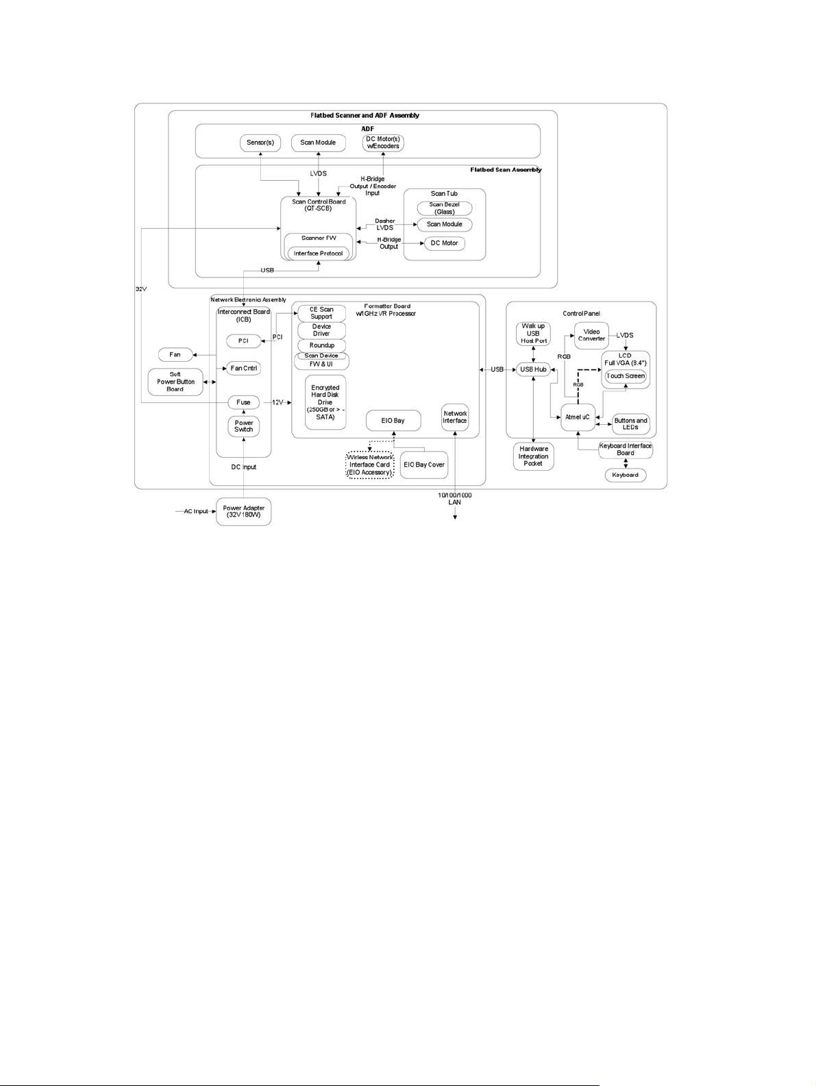
Figure 1-1 Hardware subassemblies
2 Chapter 1 Theory of operation ENWW
Page 13

Flatbed scanner and ADF assembly
The scanner can scan paper up to 216 mm (8.5 in) x 863.6 mm (34 in) in size. Paper must be placed
in the ADF input tray or on the flatbed glass before the scanning can be initiated. Output from the
scanner is in .JPEG format and is transferred to a network using a Hi-Speed USB interface.
The major hardware components associated with this assembly are:
ADF with an integrated scan module
●
Flatbed scanner assembly
●
Scanner control-board assembly
●
ENWW
Flatbed scanner and ADF assembly
3
Page 14
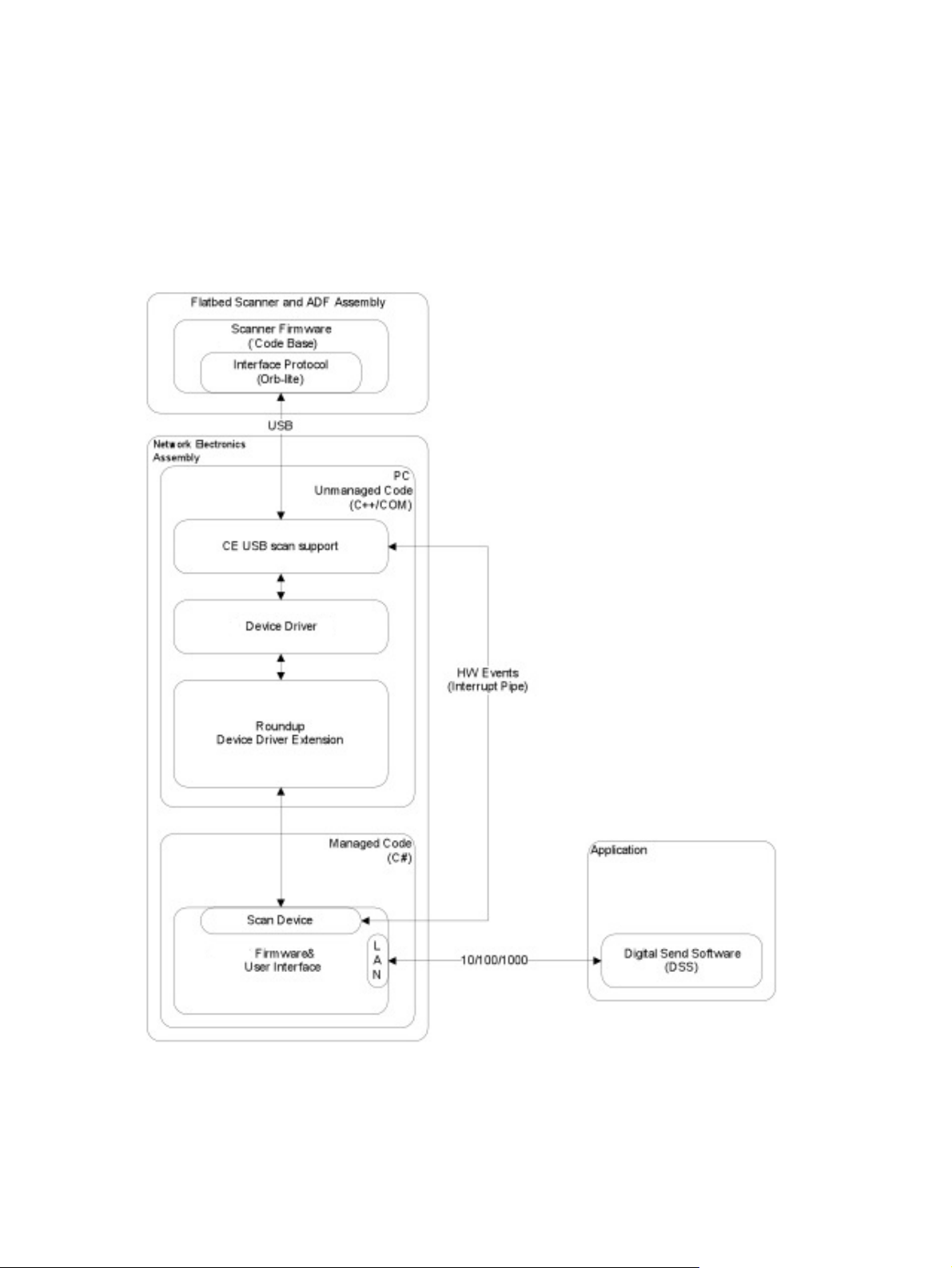
Network electronics assembly
The network electronics assembly controls all functions within the product and provides a connection to
the external gigabit network interface for the product. This assembly only accepts files from a USB
interface in .JPEG format from the flatbed scanner and ADF assembly. The assembly stores the files on
the encrypted hard disk drive for additional post-scan processing and routing based on the options
selected by the user.
Figure 1-2 Network electronics assembly overview
4 Chapter 1 Theory of operation ENWW
Page 15
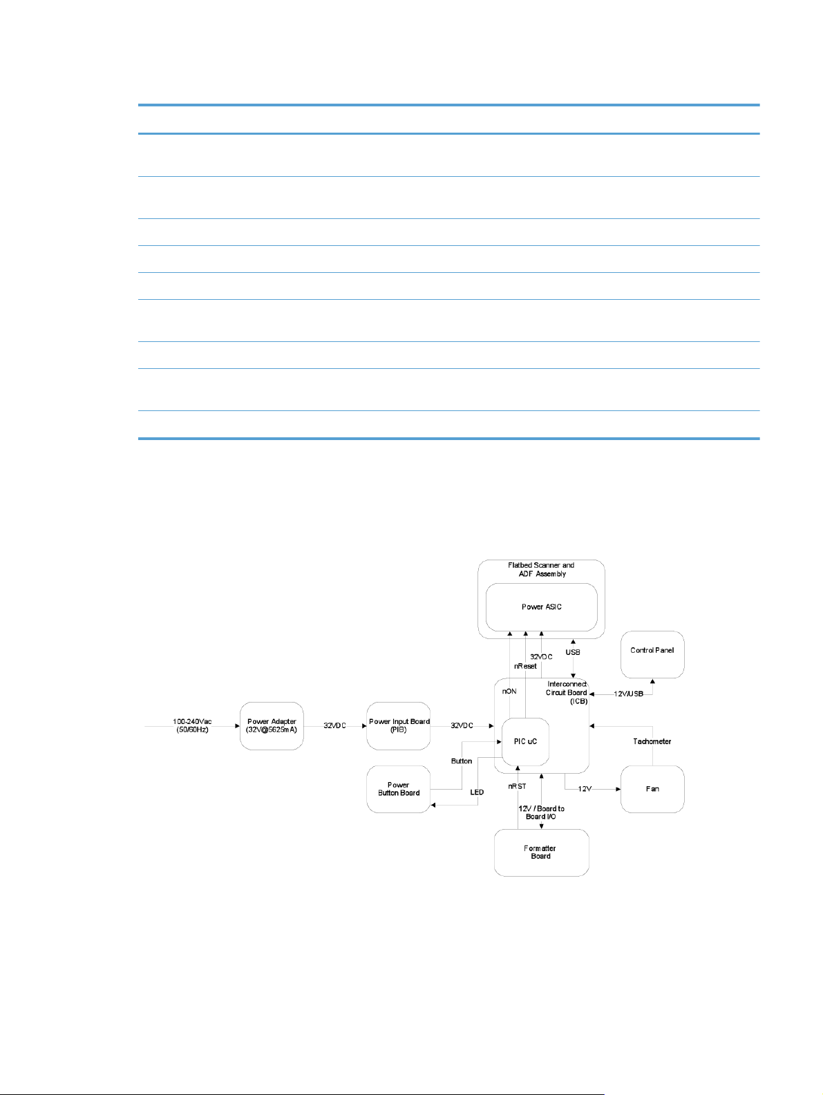
Table 1-1 Network electronic assembly components
Subassembly Subassembly Subassembly Subassembly
Network electronics (formatter
board)
Interconnect circuit board
(ICB)
Power button board
Power input board
Interface cables From ICB USB cable to scanner
USB cable to control panel
ICB cable assembly DC power cable to scanner
Power/reset control to
System power button board
(non-standard voltages)
scanner
The interconnect circuit board (ICB) subassembly within the network electronics assembly is the main
communication interface for all system assemblies. This ICB controls the power sequencing of all
assemblies and the system fan. All communication interfaces are routed through this assembly.
Figure 1-3 ICB connections
ENWW
Network electronics assembly
5
Page 16

User interface assembly
The user interface assembly has a 203.2 mm (8 in) color LCD display with and integrated touchscreen
and a full physical keyboard. The user interface assembly also includes:
A USB-host interface connection with an integrated cover for sending output files to a USB storage
●
accessory
A fleet-compliant hardware integration pocket (HIP)
●
Status LEDs
●
Physical buttons
●
The user interface assembly communicates with the network electronics assembly using a USB interface
through the ICB assembly.
Table 1-2 User interface assembly components
Subassembly Subassembly
Control-panel assembly
Physical keyboard Keyboard interface board
Cables 24-pin FFC from control panel to keyboard interface board
6 Chapter 1 Theory of operation ENWW
Page 17

2 Removal and replacement
Introduction
●
Removal and replacement strategy
●
Electrostatic discharge
●
Required tools
●
Types of screws
●
Service approach
●
Customer self repair (CSR) assemblies
●
Internal assemblies
●
NOTE: Your product might not appear exactly as the one shown in the photos in this chapter.
Although details such as the color of the external panels and covers might be different than your
product, the procedures in this chapter are appropriate for your product.
ENWW 7
Page 18

Introduction
This chapter describes the removal and replacement of field-replaceable units (FRUs) only.
Replacing FRUs is generally the reverse of removal. Occasionally, notes and tips are included to
provide directions for difficult or critical replacement procedures.
HP does
Note the length, diameter, color, type, and location of each screw. Be sure to return each screw to its
original location during reassembly.
Incorrectly routed or loose wire harnesses can interfere with other internal components and can become
damaged or broken. Frayed or pinched harness wires can be difficult to find. When replacing wire
harnesses, always use the provided wire loops, lance points, or wire-harness guides and retainers.
not
support repairing individual subassemblies or troubleshooting to the component level.
8 Chapter 2 Removal and replacement ENWW
Page 19

Removal and replacement strategy
WARNING! Turn the product off, wait 5 seconds, and then remove the power cord before
attempting to remove an assembly. If this warning is not followed, severe injury can result, in addition
to damage to the product. The power must be on for certain functional checks during troubleshooting.
However, disconnect the power supply during parts removal.
Never operate or service the product with the protective cover removed from the laser/scanner
assembly. The reflected beam, although invisible, can damage your eyes.
The sheet-metal parts can have sharp edges. Be careful when handling sheet-metal parts.
CAUTION: Do not bend or fold the flat flexible cables (FFCs) during removal or installation. Also, do
must
not straighten pre-folds in the FFCs. You
an FFC into a connector can cause a short circuit in a PCA.
NOTE: To install a self-tapping screw, first turn it counterclockwise to align it with the existing thread
pattern, and then carefully turn it clockwise to tighten. Do not overtighten. If a self-tapping screw-hole
becomes stripped, repair the screw-hole or replace the affected assembly.
TIP: For clarity, some photos in this chapter show components removed that would not be removed to
service the product. If necessary, remove the components listed at the beginning of a procedure before
proceeding to service the product.
fully seat all FFCs in their connectors. Failure to fully seat
ENWW
Removal and replacement strategy
9
Page 20

Electrostatic discharge
CAUTION: Some parts are sensitive to electrostatic discharge (ESD). Look for the ESD reminder
when removing product parts. Always perform service work at an ESD-protected workstation or mat, or
use an ESD strap. If an ESD workstation, mat, or strap is not available, ground yourself by touching the
before
sheet-metal chassis
Protect the ESD-sensitive parts by placing them in ESD pouches when they are out of the product.
touching an ESD-sensitive part.
10 Chapter 2 Removal and replacement ENWW
Page 21

Required tools
Torx screwdrivers, size 10, 15, and 20
●
Small flat blade screwdriver
●
Needle-nose pliers
●
ESD mat or ESD strap (if one is available)
●
Penlight (optional)
●
USB thumbdrive
●
ENWW
Required tools
11
Page 22
Types of screws
This table describes the screws that are used in the product and provides guidelines to help determine
where each type of screw is used. The screws can vary in length depending on the thickness of the
material that is being fastened.
Always note where each type of screw is located and replace each one in its original location.
WARNING! Make sure that components are replaced with the correct screw type. Using the
incorrect screw (for example, substituting a long screw for the correct shorter screw) can cause damage
to the product or interfere with product operation. Do not intermix screws that are removed with one
component with the screws that are removed from another component.
TIP: When you are disassembling the product, place the screws into the chassis holes from which
they were removed. This prevents their loss, and ensures that the proper type and length of screw for
each location is used when the product is reassembled.
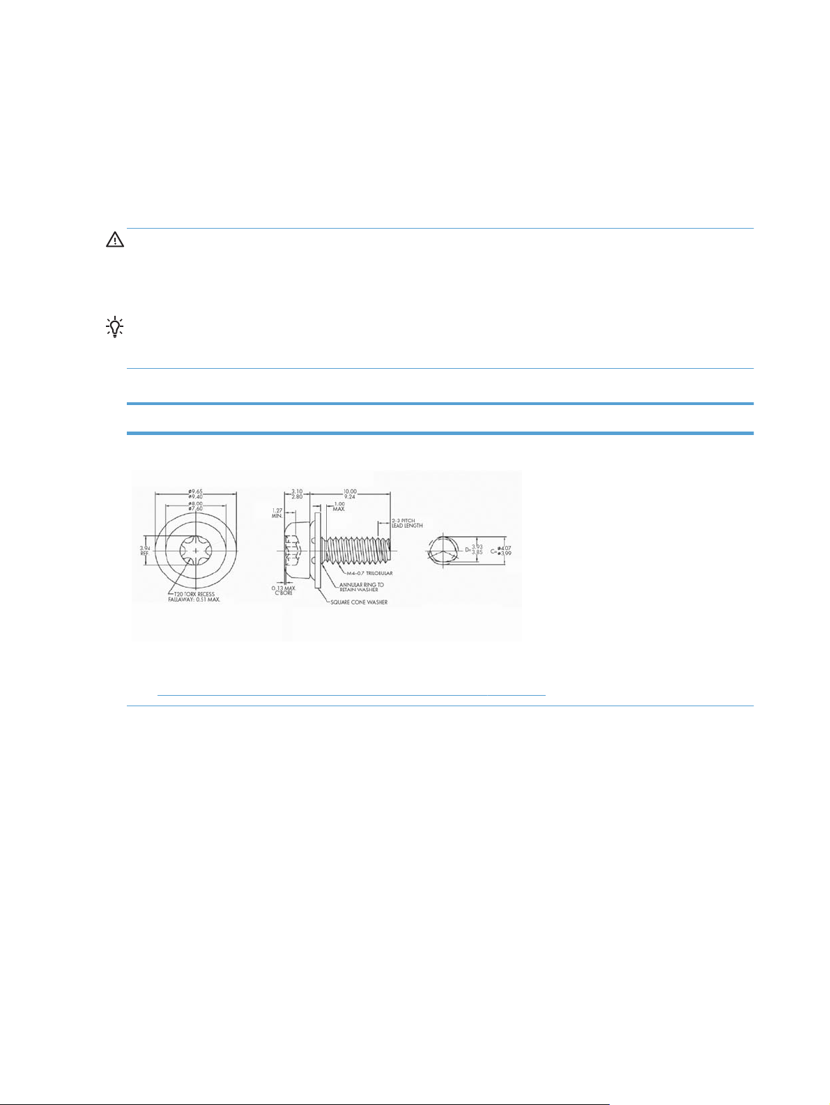
Table 2-1 Common fasteners used in this product
Screw type
Silver Torx head 4 x 10 mm screw with cone washer
This screw type is shown in the following figure:
Figure 2-31 Remove the flatbed scanner and ADF assembly (1 of 7) on page 39
●
12 Chapter 2 Removal and replacement ENWW
Page 23
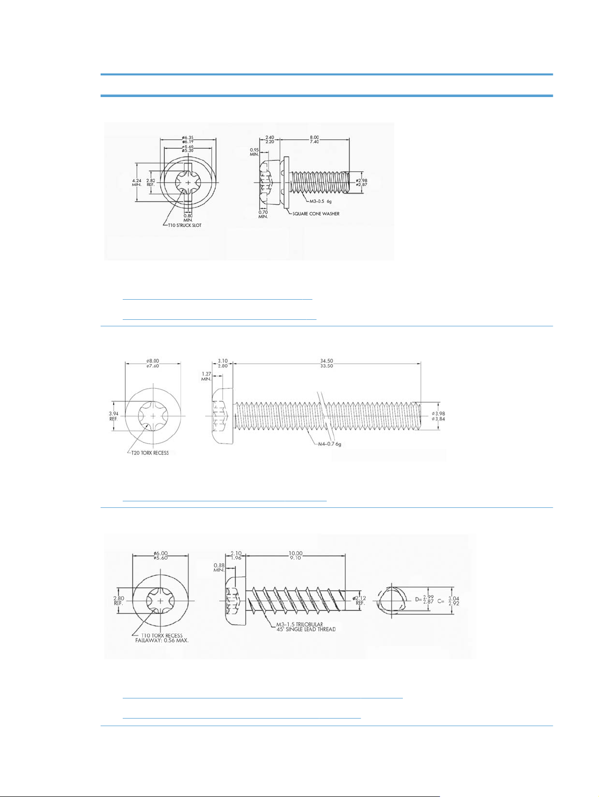
Table 2-1 Common fasteners used in this product (continued)
Screw type
Silver Torx head 3 x 8 mm screw with spring washer
This screw type is shown in the following figures:
Figure 2-61 Remove the interconnect PCA on page 56
●
Figure 2-65 Remove the DC controller PCA on page 58
●
Torx head 4 x 34 mm screw
ENWW
This screw type is shown in the following figure:
Figure 2-63 Remove the fan assembly (2 of 3) on page 57
●
Torx head 3 x 10 mm screw
This screw type is shown in the following figures:
Figure 2-32 Remove the flatbed scanner and ADF assembly (2 of 7) on page 40
●
Figure 2-38 Remove the power-button assembly (1 of 3) on page 44
●
Types of screws
13
Page 24
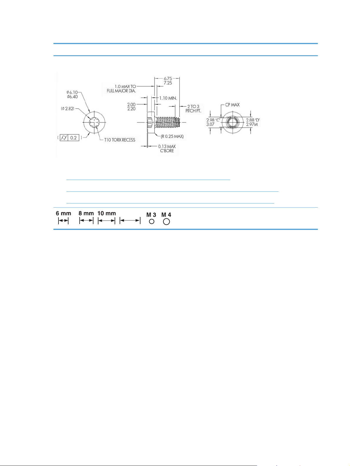
Table 2-1 Common fasteners used in this product (continued)
12 mm
Screw type
Torx head 3 x 7.25 mm screw
This screw type is shown in the following figures:
Figure 2-35 Remove the flatbed scanner and ADF assembly (5 of 7) on page 41
●
Figure 2-41 Remove the scanner cable, control-panel cable, and interconnect cable (1 of 4) on page 46
●
Figure 2-58 Remove the interconnect PCA, fan assembly, and DC connector PCA (4 of 6) on page 55
●
12 mm
Screw measurement guide
14 Chapter 2 Removal and replacement ENWW
Page 25

Service approach
Before performing service
Turn off the power using the power switch.
●
Unplug the power cable and network cable.
●
Place the product on an ESD workstation or mat, or use an ESD strap (if one is available). If an
●
ESD workstation, mat, or strap is not available, ground yourself by touching the sheet-metal
chassis
NOTE: Some procedures require that you backup product data prior to replacing the assembly.
Backup product data
To ensure that customer-specific configuration information and data are preserved, back up the product
data to a portable USB storage device prior to removing these assemblies. Restore the data after
replacing the assembly.
NOTE: You can also backup product data using the HP Embedded Web Server (EWS). The EWS
backs up product data to a customer specified network folder instead of the products hard drive. See
the product user guide for information.
before
touching an ESD-sensitive part.
1. From the Home screen on the product control panel, touch the Device Maintenance button.
2. Open the following menus:
Backup/Restore
●
Backup Data
●
Backup Now
●
NOTE: Backups are stored on the hard disk drive, including regularly scheduled backups. You
can export backups to a USB storage device from the hard disk drive.
3. Insert the portable USB storage device.
4. Touch Export Last Backup
5. Enter the password and confirm the password. Touch OK.
After performing service
Connect the network cable, and then plug in the power cable.
●
NOTE: Some procedures require that you perform a restore step after to replacing the assembly.
ENWW
Service approach
15
Page 26

Restore product data
To ensure that customer-specific configuration information and data are preserved, back up the product
data to a portable USB storage device prior to removing these assemblies. Restore the data after
replacing the assembly.
NOTE: You can also restore product data using the Embedded Web Server (EWS). See the product
user guide for information.
1. From the Home screen on the product control panel, touch the Device Maintenance button.
2. Open the following menus:
Backup/Restore
●
Restore Data
●
3. Insert the portable USB storage device.
4. Select the backup file, and then touch Restore.
5. Touch Restore.
Save and repair process
The save and repair process occurs automatically whenever the formatter PCA, interconnect PCA, or
encrypted hard disk drive (HDD) are replaced. This process is transparent to the user.
CAUTION: Replacing the formatter PCA and interconnect PCA at the same time or swapping these
assemblies between products can render the product unusable.
Formatter PCA: When a replacement formatter PCA is installed and the product is turned on,
●
NVRAM values from the interconnect PCA are transferred automatically to the replacement
formatter PCA. This process allows the product to return to normal operation with all of the
necessary product history.
Interconnect PCA: When a replacement interconnect PCA is installed, NVRAM values from the
●
formatter PCA are transferred automatically to the replacement interconnect PCA. This process
allows the product to return to normal operation with all of the necessary product history.
Hard disk drive (HDD): When a replacement hard disk drive is installed and product is turned on,
●
the replacement hard disk drive is locked to the formatter PCA of the product. The encryption key
is placed in the NVRAM of the formatter PCA and copied to the NVRAM of the interconnect PCA.
This allows the backed up NVRAM values from the interconnect PCA to be restored to a
replacement formatter PCA when either the formatter PCA or interconnect PCA are replaced. This
process also allows the hard disk drive to function when it is transferred from a defective formatter
PCA to a replacement formatter PCA. The hard disk drive cannot be used in another product or
accessed from outside the product.
Post-service test
Perform the following test to verify that the repair or replacement was successful.
16 Chapter 2 Removal and replacement ENWW
Page 27

Quality test
1. Verify that you have completed the necessary reassembly steps.
2. Verify that the power cord and network cable are correctly connected, and then turn on the
3. Verify that the control panel shows the product in Ready mode.
4. Perform the scanning features of the product to ensure the product is functioning correctly. See the
5. If necessary, restore any customer-specified settings.
6. Clean the outside of the product with a damp cloth.
product.
product user guide for information.
ENWW
Service approach
17
Page 28
Customer self repair (CSR) assemblies
ADF rollers
NOTE: Always replace the separation pad when replacing the ADF rollers. The ADF rollers and
separation pad are included in the ADF roller replacement kit.
The ADF roller replacement kit is a consumable and is not covered under warranty or standard service
agreements.
NOTE: HP recommends that you replace the rollers every 100,000 scans.
Remove the ADF rollers:
CAUTION: Do not touch the rollers. Oils from your fingers can impact performance.
NOTE: If the product is on and you open and close the ADF hatch, the attention message If
document feeder roller cleanup is complete, clear message displays. Touch Cancel to clear
the message.
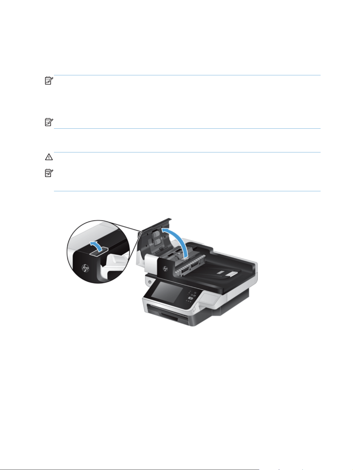
1. Open the automatic document feeder (ADF) hatch.
Figure 2-1 Remove the ADF rollers (1 of 1)
18 Chapter 2 Removal and replacement ENWW
Page 29
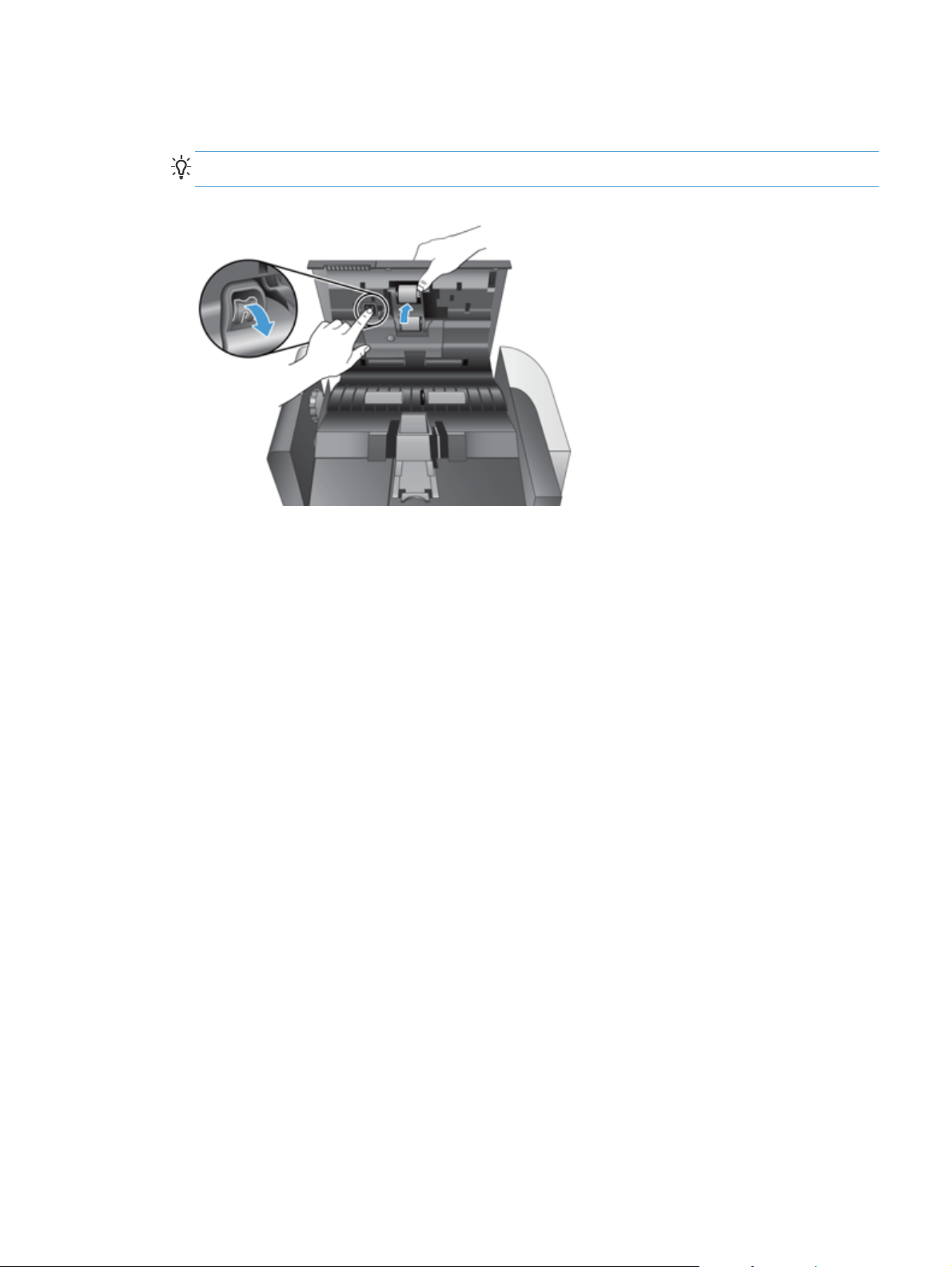
2. Slide your fingertip behind the tab on the roller assembly door, and then pull gently forward and
down to open the door.
TIP: Lift the ADF input tray slightly to make it easier to reach the tab.
Figure 2-2 Remove the ADF rollers (1 of 2)
ENWW
Customer self repair (CSR) assemblies
19
Page 30
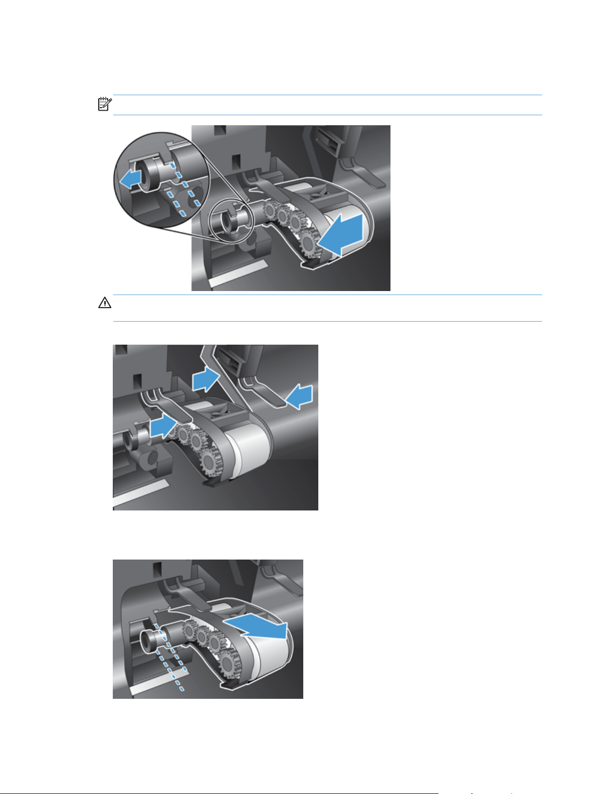
3. Holding the roller assembly door down and out of the way, grasp the roller assembly and slide it
to the left to release it from the enclosure.
NOTE: You might feel a slight resistance when sliding the roller assembly.
CAUTION: Take care not to press down on the alignment tabs or against the tab to the right of
the roller assembly.
Figure 2-3 Remove the ADF rollers (1 of 3)
4. Remove the roller assembly.
Figure 2-4 Remove the ADF rollers (1 of 4)
20 Chapter 2 Removal and replacement ENWW
Page 31

Separation pad
NOTE: Always replace the ADF rollers when replacing the separation pad. The ADF rollers and
separation pad are included in the ADF roller replacement kit.
CAUTION: Do not touch the pad. Oils from your fingers can impact performance.
1. Open the automatic document feeder (ADF) hatch.
Figure 2-5 Remove the separation pad (1 of 3)
2. Push the separation pad latch to release the separation pad.
TIP: Raise the ADF input tray slightly.
Figure 2-6 Remove the separation pad (2 of 3)
ENWW
Customer self repair (CSR) assemblies
21
Page 32

3. Lift the separation pad component to release it from its housing.
Reinstallation tip Make sure the spring seats properly on the new separation pad by pressing
down on the separation pad with a pencil or screwdriver after the pad is installed.
Figure 2-7 Remove the separation pad (3 of 3)
Update the document feeder kit replacement history
After installing new ADF rollers and a separation pad, update the product maintenance history:
1. From the Home screen on the product control panel, touch the Administration button.
2. Open the following menus:
Manage Supplies
●
Reset Supplies
●
New Document Feeder Kit
●
3. Touch Reset.
Set the Very Low Settings option from the control panel
1. From the Home screen on the product control panel, touch the Administration button.
2. Open the following menus:
Calibrate/Cleaning
●
Manage Supplies
●
Supply Settings
●
New Document Feeder Kit
●
22 Chapter 2 Removal and replacement ENWW
Page 33

3. In the Document feeder kit low box, enter a percentage of the total scans at which the
product displays a message to replace the document feeder kit.
4. Select one of the following options:
Select the Stop option to set the product to stop scanning until you replace the document
●
feeder kit.
Select the Prompt to continue option to set the product to stop scanning and prompt you to
●
replace the document feeder kit. You can acknowledge the prompt and continue scanning.
Select the Continue option to set the product to alert you that the document feeder kit needs
●
to be replaced, but to continue scanning.
ENWW
Customer self repair (CSR) assemblies
23
Page 34

Control-panel assembly
1. Raise the scanner lid.
2. Lift the left side of the control panel to release it from the product.
Figure 2-8 Remove the control-panel assembly (1 of 3)
3. Disconnect the FFC (callout 1), and then gently pull the FFC through the cable restraint (callout 2).
Figure 2-9 Remove the control-panel assembly (2 of 3)
24 Chapter 2 Removal and replacement ENWW
Page 35

4. Disconnect the control-panel cable and then remove the control panel.
Figure 2-10 Remove the control-panel assembly (3 of 3)
NOTE: If the firmware is in a compressed file, extract the file before saving it to the USB storage
device. Only files with a .bdl extension are valid firmware update files.
Reinstall the control-panel assembly
The replacement control-panel assembly ships with default calibration values. After installing a new
control-panel assembly, calibrate and test the control-panel. See
more information.
Control-panel checks on page 73 for
ENWW
Customer self repair (CSR) assemblies
25
Page 36

Hard disk drive
CAUTION: ESD sensitive component.
CAUTION: Replacing the hard disk drive and formatter PCA, hard disk drive and interconnect PCA,
or formatter PCA and interconnect PCA at the same time can render the product unusable. Swapping
these assemblies between products can also render the product unusable.
Remove the hard disk drive
1. If replacing the hard disk drive, back up the product data before removing. See Backup product
data on page 15.
2. Loosen two thumbscrews (callout 1), and then remove the formatter.
Figure 2-11 Remove the formatter
26 Chapter 2 Removal and replacement ENWW
Page 37

3. Disconnect the cable from the hard disk drive, gently lift the drive rail lever on the left leading
edge of the hard disk drive (1), and then slide the drive forward (2). Lift the hard disk drive out of
the drawer assembly.
Figure 2-12 Remove the hard disk drive (1 of 3)
ENWW
Customer self repair (CSR) assemblies
27
Page 38

4. Remove the black plastic mounting rails from the hard drive, and then install them on the new hard
drive.
Figure 2-13 Remove the hard disk drive (2 of 3)
Figure 2-14 Remove the hard disk drive (3 of 3)
28 Chapter 2 Removal and replacement ENWW
Page 39

Reinstall the hard disk drive
NOTE: The replacement hard disk drive is locked to the formatter PCA of the product the first time the
product is turned on after installation. The encryption key is placed in the NVRAM of the formatter PCA
and copied to the NVRAM of the interconnect PCA. This allows the backed up NVRAM values from the
interconnect PCA to be restored to a replacement formatter PCA when either the formatter PCA or
interconnect PCA are replaced. This process allows the hard disk drive to function when it is transferred
from a defective formatter PCA to a replacement formatter PCA. The hard disk drive cannot be used in
another product or accessed from outside the product.
1. Tuck the drive cable under the cable restraint.
Figure 2-15 Reinstall the hard disk drive
2. After installing a replacement hard disk drive, you must reload the firmware by performing a
firmware upgrade.
Reload the firmware
1. Go to
www.hp.com/support and select the country/region and language.
2. Select Drivers and Software and then search for the product. Select the product from search
results.
3. Select Cross operating system (BIOS, Firmware, Diagnostics, etc).
4. Select the appropriate firmware update file.
NOTE: If the firmware is in a compressed file, extract the .bdl file before saving it to a USB
thumbdrive. Only files with a .bdl extention are valid for firmware updates.
5. Download and copy the firmware upgrade file to the root directory of a USB storage accessory.
The firmware upgrade file has a .bdl extension.
6. Insert the USB storage accessory into the USB port on the bottom edge of the control panel.
7. Connect all cables and turn on the product. Error: 99.09.62 Not Bootable or a similar
message displays. Press the Start
button to continue.
ENWW
Customer self repair (CSR) assemblies
29
Page 40

8. Wait for the preboot menu to display on the control-panel display, and then press the up or down
navigation arrows on the keyboard to scroll to Administrator. Press the Start
button to select it.
9. Press the up or down keys on the keyboard to scroll to Administrator. Press the Start
button to
select it.
10. Press down arrow key on the keyboard to scroll to Download. Press the Start
11. Press the up or down keys on the keyboard to scroll to USB Thumbdrive. Press the Start
button to select it.
button
to select it.
12. Several .bdl files might be listed. Press the up or down keys on the keyboard to scroll to the
firmware upgrade file that you downloaded. Press the Start
button to select it. Wait while the
file transfers. When the transfer is complete, the message Complete displays on the control-panel
display.
13. Press and hold the power button to turn off the product (approximately 10 seconds). Remove the
USB storage accessory, and then turn the product on. Wait for several minutes while the product
initializes. If the upgrade is unsuccessful, try transferring the firmware upgrade file again.
14. If you created a backup of the product data prior to replacing the hard disk drive, restore the data
from the device or network location where the backup was saved. See
Restore product data
on page 16.
30 Chapter 2 Removal and replacement ENWW
Page 41

Formatter PCA
Remove the formatter PCA and transfer the hard drive
CAUTION: ESD sensitive component.
CAUTION: Replacing the hard disk drive and formatter PCA, hard disk drive and interconnect PCA,
or formatter PCA and interconnect PCA at the same time can render the product unusable. Swapping
these assemblies between products can also render the product unusable. This procedure specifies
replacing the formatter PCA and reinstalling the existing hard drive on the new formatter PCA.
NOTE: If replacing the hard disk drive, back up the product data before removing. See Backup
product data on page 15.
1. Loosen two thumbscrews (callout 1), and then remove the formatter.
Figure 2-16 Remove the formatter (1 of 11)
ENWW
Customer self repair (CSR) assemblies
31
Page 42

2. Slide the formatter PCA chassis out of the product.
Figure 2-17 Remove the formatter (2 of 11)
3. Disconnect the hard drive connector
Figure 2-18 Remove the formatter (3 of 11)
32 Chapter 2 Removal and replacement ENWW
Page 43

4. Release one tab (callout 1) and then slide the hard drive out of the carriage.
Figure 2-19 Remove the formatter (4 of 11)
1
Figure 2-20 Remove the formatter (5 of 11)
ENWW
Customer self repair (CSR) assemblies
33
Page 44

5. Remove the black plastic mounting rails from the old hard drive, and then install them on the new
hard drive.
Figure 2-21 Remove the formatter (6 of 11)
Figure 2-22 Remove the formatter (7 of 11)
6. Install the hard drive in the carriage on the new formatter.
Figure 2-23 Remove the formatter (8 of 11)
34 Chapter 2 Removal and replacement ENWW
Page 45

7. Reinstall the connector.
Figure 2-24 Remove the formatter (9 of 11)
8. Slide the formatter PCA chassis into the product.
Figure 2-25 Remove the formatter (10 of 11)
ENWW
Customer self repair (CSR) assemblies
35
Page 46

9. Tighten the two thumbscrews.
Figure 2-26 Remove the formatter (11 of 11)
Reinstall the formatter PCA
NVRAM values including the encryption key for the hard disk drive are restored to the replacement
formatter PCA from the NVRAM of the interconnect PCA when the product is turned on. The product
returns to normal operation with all of the product history loaded in the NVRAM of the formatter PCA.
Keyboard assembly
1. Slide the four tabs at the top of the keyboard toward the bottom of the keyboard.
Figure 2-27 Remove the keyboard assembly (1 of 4)
36 Chapter 2 Removal and replacement ENWW
Page 47

2. Release the four tabs at the bottom of the keyboard.
Figure 2-28 Remove the keyboard assembly (2 of 4)
3. Lift the keyboard from the product. Note the orientation of the flat flexible cable (FFC) for
reinstallation.
Figure 2-29 Remove the keyboard assembly (3 of 4)
ENWW
Customer self repair (CSR) assemblies
37
Page 48

4. Release the cable lock to release the FFC, and then remove the keyboard.
Figure 2-30 Remove the keyboard assembly (4 of 4)
38 Chapter 2 Removal and replacement ENWW
Page 49

Internal assemblies
Flatbed scanner and ADF assembly
Before proceeding, remove the following components:
Control-panel assembly. See
●
Control-panel assembly on page 24.
Remove the flatbed scanner and ADF assembly:
1. From the front of the scanner, remove four screws.
Figure 2-31 Remove the flatbed scanner and ADF assembly (1 of 7)
ENWW
Internal assemblies
39
Page 50

2. From the back of the scanner, remove five screws.
Figure 2-32 Remove the flatbed scanner and ADF assembly (2 of 7)
3. Carefully release the back cover.
NOTE: The serial number for the product is on the back cover. Do not lose or damage the cover.
Figure 2-33 Remove the flatbed scanner and ADF assembly (3 of 7)
40 Chapter 2 Removal and replacement ENWW
Page 51

4. Remove the back cover.
Figure 2-34 Remove the flatbed scanner and ADF assembly (4 of 7)
5. Remove two screws.
Figure 2-35 Remove the flatbed scanner and ADF assembly (5 of 7)
ENWW
Internal assemblies
41
Page 52

6. Lift the flatbed scanner and ADF assembly.
Figure 2-36 Remove the flatbed scanner and ADF assembly (6 of 7)
7. Disconnect three cables and then remove the flatbed scanner and ADF assembly.
Figure 2-37 Remove the flatbed scanner and ADF assembly (7 of 7)
Reinstall the flatbed scanner and ADF assembly
NOTE: After the flatbed scanner and ADF assembly is replaced, the product compares the firmware
version on the new assembly with the firmware on the product. If the firmware on the product is newer,
the firmware on the assembly is updated. The product will restart multiple times during the update
process.
After installing a new flatbed scanner and ADF assembly, reset the cycle counts.
42 Chapter 2 Removal and replacement ENWW
Page 53

Reset the cycle counts
1. From the Home screen on the product control panel, touch the Device Maintenance button.
2. Touch the Service button and log in.
3. Touch the Cycle Counts button.
4. Reset the following counts to 0:
Document Feeder Count
●
Clean Rollers Count
●
Flatbed Count
●
ADF Simplex Count
●
ADF Duplex Count
●
NOTE: Do not reset the Send Scan Count setting.
ENWW
Internal assemblies
43
Page 54

Power-button assembly
Before proceeding, remove the following components:
Control-panel assembly. See
●
Flatbed scanner and ADF assembly. See
●
Control-panel assembly on page 24.
Remove the power-button assembly
CAUTION: ESD sensitive component.
1. Disconnect one connector (callout 1), and remove two screws (callout 2).
Figure 2-38 Remove the power-button assembly (1 of 3)
1
Flatbed scanner and ADF assembly on page 39
2
44 Chapter 2 Removal and replacement ENWW
Page 55

2. Remove the power-button assembly.
Figure 2-39 Remove the power-button assembly (2 of 3)
Reinstall the power-button assembly
When installing the power-button assembly, install the button first and then install the PCA.
▲
Figure 2-40 Remove the power-button assembly (3 of 3)
ENWW
Internal assemblies
45
Page 56

Interconnect cable, scanner cable, and control-panel cable
Before proceeding, remove the following components:
Control-panel assembly. See
●
Flatbed scanner and ADF assembly. See
●
Control-panel assembly on page 24.
Flatbed scanner and ADF assembly on page 39.
Remove the scanner cable, control-panel cable, and interconnect cable
1. Remove four screws
Figure 2-41 Remove the scanner cable, control-panel cable, and interconnect cable (1 of 4)
2. Release two tabs and remove the sheet-metal plate.
Figure 2-42 Remove the scanner cable, control-panel cable, and interconnect cable (2 of 4)
46 Chapter 2 Removal and replacement ENWW
Page 57

3. Disconnect three cables (callout 1).
Figure 2-43 Remove the scanner cable, control-panel cable, and interconnect cable (3 of 4)
1
4. Identify the cable to be removed:
Scanner cable (callout 1). See
●
Control-panel cable (callout 2). See
●
Interconnect cable (callout 3). See
●
Figure 2-44 Remove the scanner cable, control-panel cable, and interconnect cable (4 of 4)
Remove the scanner cable on page 48.
Remove the control-panel cable on page 49.
Remove the interconnect cable on page 51.
2
1
3
ENWW
Internal assemblies
47
Page 58

Remove the scanner cable
1. If connected, disconnect the scanner cable from the interconnect PCA.
Figure 2-45 Remove the scanner cable (1 of 3)
2. Release the cable from one cable clamp.
Figure 2-46 Remove the scanner cable (2 of 3)
48 Chapter 2 Removal and replacement ENWW
Page 59

3. Remove the scanner cable.
Figure 2-47 Remove the scanner cable (3 of 3)
Remove the control-panel cable
1. If connected, disconnect the control-panel cable from the interconnect PCA.
Figure 2-48 Remove the control-panel cable (1 of 3)
ENWW
Internal assemblies
49
Page 60

2. Release the cable from one cable clamp.
Figure 2-49 Remove the control-panel cable (2 of 3)
3. Remove the control-panel cable.
Figure 2-50 Remove the control-panel cable (3 of 3)
50 Chapter 2 Removal and replacement ENWW
Page 61

Remove the interconnect cable
1. If connected, disconnect the interconnect cable from the interconnect PCA.
Figure 2-51 Remove the interconnect cable (1 of 4)
2. Release the cable from one cable clamp.
Figure 2-52 Remove the interconnect cable (2 of 4)
ENWW
Internal assemblies
51
Page 62

3. Release the cable from one cable clamp (callout 1) and disconnect one connector (callout 2).
Figure 2-53 Remove the interconnect cable (3 of 4)
1
2
4. Remove the interconnect cable.
Figure 2-54 Remove the interconnect cable (4 of 4)
52 Chapter 2 Removal and replacement ENWW
Page 63

Interconnect PCA, fan assembly, and DC controller PCA
NOTE: When a replacement interconnect PCA is installed and the product is turned on, it restores the
NVRAM values from the NVRAM of the formatter PCA. This process allows the product to return to
normal operation with all of the necessary product history.
CAUTION: Replacing the hard disk drive and formatter PCA, hard disk drive and interconnect PCA,
or formatter PCA and interconnect PCA at the same time can render the product unusable. Swapping
these assemblies between products can also render the product unusable.
Before proceeding, remove the following components:
Control-panel assembly. See
●
Flatbed scanner and ADF assembly. See
●
Control-panel assembly on page 24.
Flatbed scanner and ADF assembly on page 39.
Remove the interconnect PCA, fan assembly, and DC controller PCA:
CAUTION: ESD sensitive component.
1. Remove four screws.
Figure 2-55 Remove the interconnect PCA, fan assembly, and DC connector PCA (1 of 6)
ENWW
Internal assemblies
53
Page 64

2. Release two tabs and remove the sheet-metal plate.
Figure 2-56 Remove the interconnect PCA, fan assembly, and DC connector PCA (2 of 6)
3. Disconnect three cables (callout 1).
Figure 2-57 Remove the interconnect PCA, fan assembly, and DC connector PCA (3 of 6)
1
54 Chapter 2 Removal and replacement ENWW
Page 65

4. Remove nine screws.
Figure 2-58 Remove the interconnect PCA, fan assembly, and DC connector PCA (4 of 6)
5. Slide the sheet-metal drawer out of the product.
Figure 2-59 Remove the interconnect PCA, fan assembly, and DC connector PCA (5 of 6)
ENWW
Internal assemblies
55
Page 66

6. Identify the PCA or assembly to be removed:
Interconnect PCA (callout 1). See
●
Fan assembly (callout 2). See
●
DC controller PCA (callout 3). See
●
Figure 2-60 Remove the interconnect PCA, fan assembly, and DC connector PCA (6 of 6)
Remove the interconnect PCA on page 56.
Remove the fan assembly on page 57.
Remove the DC controller PCA on page 58.
31 2
Remove the interconnect PCA
Disconnect two connectors (callout 1), remove four screws (callout 2), and remove the interconnect
▲
PCA.
Figure 2-61 Remove the interconnect PCA
2
1
56 Chapter 2 Removal and replacement ENWW
Page 67

Remove the fan assembly
1. Release one cable retainer.
Figure 2-62 Remove the fan assembly (1 of 3)
2. Disconnect one connector (callout 1) and then remove four screws (callout 2).
Figure 2-63 Remove the fan assembly (2 of 3)
1
2
ENWW
Internal assemblies
57
Page 68

3. Remove the fan assembly.
Figure 2-64 Remove the fan assembly (3 of 3)
Remove the DC controller PCA
Disconnect one connector (callout 1), remove three screws (callout 2), and remove the DC
▲
controller PCA.
Figure 2-65 Remove the DC controller PCA
2
1
58 Chapter 2 Removal and replacement ENWW
Page 69

3 Solve problems
Solve problems checklist
●
Administration Menu Map
●
Preboot menu options
●
Current settings page
●
Troubleshooting process
●
Tools for troubleshooting
●
Clear jams
●
Solve paper-handling problems
●
Clean the product
●
Solve connectivity problems
●
Service mode functions
●
Preboot menu options
●
Solve fax problems
●
Solve e-mail problems
●
Product updates
●
ENWW 59
Page 70

Solve problems checklist
Simple issues such as smudges on the scanning glass or loose cables can cause your product to
produce fuzzy scans, operate in an unexpected manner, or fail to operate. Always check the following
items when you encounter scanning problems.
If scans are fuzzy, check to see if the scanning strip to the left of the scanning glass is dirty or
●
smudged. If so, clean the scanning strip.
If you are scanning a document that will be analyzed using Optical Character Recognition (OCR),
make sure that the original document is clear enough to be analyzed.
Make sure that the Ethernet and power cables are firmly seated in their respective connectors on
●
the back of the product, and that the power cord is plugged into a working electrical outlet or
surge protector.
Ensure that the product is receiving power.
●
Check that the green LED on the power supply case is on.
◦
If the green LED is not on, ensure that power is available to the power outlet or surge
◦
protector that the power supply is plugged into.
If power is available to the power outlet or surge protector but the green LED is still not on,
◦
the power supply might be defective.
Make sure that the power LED and heartbeat LED on the formatter are functioning correctly.
●
Make sure that the product buttons are enabled.
●
Press and hold the power button for 10 seconds to turn off the product, wait 30 seconds, and then
●
press the Power button again to turn on the product.
Make sure the automatic document feeder (ADF) hatch is closed.
●
Verify that the product is connected to the LAN, and that the product is correctly configured to use
●
the network.
If you continue to have problems, it is possible that the firmware or associated drivers are out of date or
have become corrupted. Go to
product.
www.hp.com/support to locate firmware and driver updates for the
60 Chapter 3 Solve problems ENWW
Page 71

Administration Menu Map
The Administration Menu Map report presents the entire structure of the Administration menu so you
can identify how to navigate to any option.
1. From the Home screen on the product control panel, touch the Administration button.
2. Open the following menus:
Reports
●
Configuration/Status Pages
●
Administration Menu Map
●
3. Touch the View button to view the report.
ENWW
Administration Menu Map
61
Page 72

Preboot menu options
If an error occurs while the product is booting, an error message appears on the control-panel display.
The user can access the Preboot menus. The Error menu item will not be seen if an error did not occur.
CAUTION: The Clean Disk, or Format Disk (in newer firmware versions), option performs a disk
initialization for the entire disk. The operating system, firmware files, and third party files (among other
files) will be completely lost. HP does not recommend this action unless upgrading firmware from the
preboot menu.
Access the Preboot menu
1. Turn the product on.
2. Press and hold the Stop
3. Use the keyboard to navigate the menu.
Cold reset using the Preboot menu
1. Turn the product on.
2. Press the Stop
3. On the product keyboard press the down arrow to highlight Administrator, and then press the
enter key.
4. On the product keyboard press the down arrow to highlight Startup Options, and then press the
enter key.
5. On the product keyboard press the down arrow to highlight Cold Reset, and then press the enter
key.
6. On the product control panel press the back arrow
option, and then press the enter key on the keyboard.
NOTE: The product will initialize.
button when the Ready, Data, and Attention LEDs are illuminated solid.
button when the LED lights are illuminated solid.
button twice to highlight the Continue
62 Chapter 3 Solve problems ENWW
Page 73

Current settings page
The current settings pages provides a map of the user configurable settings that might be helpful in the
troubleshooting process.
1. From the Home screen on the product control panel, touch the Administration button.
2. Open the following menus:
Reports
●
Configuration/Status Pages
●
Current Settings Page
●
3. Touch the View button to view the report.
ENWW
Current settings page
63
Page 74

Troubleshooting process
Determine the problem source
When the product malfunctions or encounters an unexpected situation, the product control panel alerts
you to the situation. A troubleshooting flowchart helps you diagnose the root cause of the problem. The
remainder of this chapter provides steps for correcting problems.
Use the troubleshooting flowchart to pinpoint the root cause of hardware malfunctions. The
●
flowchart guides you to the section of this chapter that contains steps for correcting the
malfunction.
Before beginning any troubleshooting procedure, check the following issues:
Are supply items within their rated life?
●
Does the configuration page reveal any configuration errors?
●
NOTE: The customer is responsible for checking supplies and for using supplies that are in good
condition.
64 Chapter 3 Solve problems ENWW
Page 75

Troubleshooting flowchart
Symptom Check Possible causes Possible solutions
The control-panel display is
blank, no lights are lit, and the
product makes no sounds from
the motors.
The power outlet is not
The external power supply has
Is the power on? The power cable is
disconnected.
functioning.
failed.
1. Make sure that the power
cable is connected to the
power supply and a power
outlet or power strip. Make
sure the power supply is
connected to the product.
2. If power cable is connected
to a power strip, make sure
that power strip is
connected to the power
outlet and the power strip is
turned on. If the power strip
has a circuit breaker, reset
the circuit breaker.
See
Power-on checks
on page 68.
Test the outlet by connecting the
product to an outlet that is known
to work.
See
Power-on checks
on page 68.
If the problem persists, replace
the external power supply.
Are the subassemblies receiving
power?
See
Power-on checks
on page 68.
Bad connection to the
Bad connection to the DC
controller PCA
interconnect PCA
See
Power-on checks
on page 68.
1. Turn the power off.
2. Check all connections to the
DC controller PCA.
3. Turn the power on.
See the replacement procedure
for the DC controller PCA in the
service manual.
1. Turn the power off.
2. Check all connections to the
interconnect PCA.
3. Turn the power on.
See the replacement procedure
for the interconnect PCA in the
service manual.
ENWW
Troubleshooting process
65
Page 76

Symptom Check Possible causes Possible solutions
DC controller PCA is defective. Replace the DC controller PCA.
See the replacement procedure
for the DC controller PCA in the
service manual.
interconnect PCA is defective. Replace the interconnect PCA.
See the replacement procedure
for the interconnect PCA in the
service manual.
The control-panel display is
blank, no LED's are lit, but the
other subassemblies have power.
Is the brightness of the
Are the cables to the control
The control-panel display is
The product stops during the
startup process.
The formatter, interconnect PCA,
The firmware is corrupt. See
The firmware on an assembly is
Is the device in sleep mode? The product is in sleep mode. Touch the touchscreen display.
touchscreen display turned off?
panel connected?
What state is the touchscreen
showing?
The touchscreen display
brightness is off.
The cables are not connected. Check the cable connections.
defective.
The firmware was recently
updated.
or another assembly was recently
replaced.
not updating.
Press the + sign on the brightness
adjustment button until the
control-panel display shows.
See the replacement procedure
for the control panel in the
service manual.
Replace the control-panel
display.
See the replacement procedure
for the control-panel display in
the service manual.
Wait 5 minutes and then restart
the product.
on page 69.
Firmware startup steps
The hard drive, formatter, or
other assembly is defective.
An error or warning message
displays on the control-panel
display.
Does message display as a full
Does the message display on the
status line?
screen?
A supply limit is approaching. Follow the instructions to resolve
the warning message.
An error condition exists within
the product.
Follow the instructions to resolve
the error message.
66 Chapter 3 Solve problems ENWW
Page 77

Symptom Check Possible causes Possible solutions
The product cannot connect to
the network.
The product was reset to factory
Are network cables connected? The network cables are
Can you ping the product using
Has an IP address been assigned
to the product?
its IP address?
The product was not configured. Touch the Network Address
default settings.
disconnected.
No network connection Use the command prompt to
button on the control panel to
display the IP address.
Check the configuration from the
control-panel display or HP
Embedded Web Server.
Check each cable connection. If
the problem persists, try a
different cable or port on the hub
or transceiver.
ping the product from your
computer. For example: ping
192.168.45.39 Ensure that the
ping displays round-trip times. If
you are able to ping the product,
verify that the IP address
configuration for the product is
correct on the computer. If it is
correct, delete and then add the
product again. If the ping
command failed, verify that the
network hubs are on, and then
verify that the network settings,
the product, and the computer
are all configured for the same
network.
Is the HP Jetdirect embedded
print server functioning?
The formatter is defective. See the replacement procedure
Are the link speed and duplex
settings correct?
Is the protocol enabled? The product is not configured
The HP Jetdirect embedded print
server is not configured correctly.
The product is not configured
correctly.
correctly.
Check the HP Jetdirect LEDs on
the formatter. The top-left LED is
green and indicates the link
status. If it is off, a link has
failed. The top-right LED is
yellow. It blinks on and off to
indicate network activity.
for the formatter PCA in the
service manual.
The link speed and
communication mode of the
Jetdirect server must match the
network settings. The available
settings depend on the product
and installed Jetdirect server.
Leave the setting in automatic
mode (the default setting).
Check the protocol status using
the HP Embedded Web Server.
See the features of the HP
Embedded Web server in the
service manual.
ENWW
Troubleshooting process
67
Page 78

Symptom Check Possible causes Possible solutions
The product will not scan. Do the flatbed scanner and
document feeder start up
correctly?
The flatbed scanner and ADF
The firmware for the flatbed
scanner and ADF assembly is
corrupted.
assembly is defective.
1. Verify that the flatbed
scanner and ADF assembly
is receiving power and the
firmware is functioning by
loading a sheet of paper in
the input tray and verifying
that the Document load/
detect LED turns on.
2. Turn the product off and
then on.
3. Upgrade the product
firmware. See the firmware
upgrade process in the
service manual.
4. Restart the product.
Replace the flatbed scanner and
ADF assembly.
See the replacement procedure
for the flatbed scanner and ADF
assembly in the service manual.
Power subsystem
Power-on checks
The basic product functions should start up as soon as the product is plugged into an electrical outlet
and the power switch is pushed to the
this section to isolate and solve the problem.
Power-on troubleshooting overview
Turn on the product power. If the control-panel display remains blank, random patterns appear, or
asterisks remain on the display, perform power-on checks to locate the cause of the problem.
During normal operation, the main cooling fan begins to spin briefly after the product power is turned
on. Place your hand on the rear cover, next to the formatter. If the fan is operating, you will feel a slight
vibration and feel air passing into the product. You can also lean close to the product and hear the fan
operating. When this fan is operational, the DC side of the power supply is functioning correctly.
After the fan is operating, the scanner motor turns on (unless the top cover is open, a jam condition is
sensed, or the paper-path sensors are damaged). You should be able to visually determine if the
scanner motor is turned on if the flatbed carriage moves as it calibrates and the scanner LED lights
blink.
on
position. If the product does not start, use the information in
68 Chapter 3 Solve problems ENWW
Page 79

If the control panel is blank when you turn on the product, check the following items.
1. Make sure that the product is plugged into an active electrical outlet that delivers the correct
voltage.
2. Make sure that the power switch is in the
3. Make sure that the fan runs briefly, which indicates that the power supply is operational.
4. Make sure that the control-panel display FFC cable and USB cable are connected. Turn the power
off to check this.
5. Make sure that the formatter is seated and operating correctly. The heartbeat LED should be
blinking, and the connectivity LED should be illuminated.
6. Verify that the firmware for the flatbed scanner and ADF assembly is functioning by loading a
sheet of paper in the input tray and verifying that the Document load/detect LED turns on.
7. Use the brightness adjustment button on the control panel to make sure that it is not all the way up
or all the way down.
8. Remove any HP Jetdirect or other EIO cards, and then try to turn the product on again.
NOTE: It is important to have the control panel functional as soon as possible in the troubleshooting
process so that the control-panel display can be used to help locate product errors.
Firmware startup steps
If the product stops during the startup process, note the touchscreen display number and then review the
possible solutions.
on
position.
Touchscreen display Startup step Description Possible solutions
1 BIOS Starts the formatter 1. Check the lights on the
formatter.
2. If the lights are off, turn
the product off and then
make sure the formatter
PCA is firmly seated in
the product. Turn the
product on.
3. If the problem persists,
replace the formatter
PCA. See the
replacement procedure
in the service manual.
ENWW
Troubleshooting process
69
Page 80

Touchscreen display Startup step Description Possible solutions
2 BIOS preboot Extracts and installs the
firmware on the first startup
after a firmware upgrade
3 Operating system startup Starts Windows 1. Turn the product off and
4 Shell startup Starts the touchscreen 1. Turn the product off and
1. Turn the product off and
then on.
2. Upgrade the firmware
using the preboot menu.
3. If the problem persists,
replace the formatter
PCA. See the
replacement procedure
in the service manual.
then on.
2. Upgrade the firmware
using the preboot menu.
3. If the problem persists,
replace the hard drive.
See the replacement
procedure in the service
manual.
then on.
2. Upgrade the firmware
using the preboot menu.
3. If the problem persists,
replace the hard drive.
See the replacement
procedure in the service
manual.
5 Not used
6 Partition manager Sets up the hard drive 1. Turn the product off and
then on.
2. Check the hard drive
connections and make
sure the formatter PCA is
firmly seated in the
product.
3. If the problem persists,
replace the hard drive.
See the replacement
procedure in the service
manual.
70 Chapter 3 Solve problems ENWW
Page 81

Touchscreen display Startup step Description Possible solutions
Disk check Only Happens on hard reset Checks the disk 1. Turn the product off and
then on.
2. If the problem persists,
replace the hard drive.
See the replacement
procedure in the service
manual.
7 Installation manager Installs all other components
including the scanner
firmware
Check the HIP accessory
Check the secondary EIO
device
1. If a secondary EIO
device has been
installed, turn the
product off, remove the
device, and then turn the
product on.
2. If the product starts
properly, verify that the
firmware loaded on
product supports the EIO
device.
3. If the product does not
start, update the product
to firmware that supports
the secondary EIO
device and then reinstall
the device. If the
problem persists,
replace the EIO device.
1. If an accessory has been
installed in the hardware
integration pocket (HIP),
turn the product off,
remove the accessory
and turn the product on.
ENWW
2. If product starts
properly, verify that the
firmware on the product
supports the accessory.
If not, update the
product to firmware that
supports the accessory.
3. Reinstall the accessory. If
the problem persists,
replace the accessory.
Troubleshooting process
71
Page 82

Touchscreen display Startup step Description Possible solutions
Check the flatbed
scanner and ADF
assembly
1. Load paper in document
feeder and verify that
the document load/
detect LED turns on.
2. If the light does not turn
on, make sure all doors
and hatches are closed.
3. If the flatbed scanner
and ADF assembly has
been recently replaced,
check all cable
connections and then
restart the product.
4. If the product does not
start, upgrade the
firmware from the
preboot menu.
5. If the problem persists,
replace the flatbed
scanner and ADF
assembly. See the
replacement procedure
in the service manual.
8 Firmware startup process Starts the main program that
runs all other assemblies on
the product
Checking hardware Hardware status check Checks the status of all
hardware.
Initializing Initializing devices Initializes devices and key
NVRAM values
Turn the product off and then
on.
Follow the steps displayed in
the error message.
Follow the steps displayed in
the error message.
72 Chapter 3 Solve problems ENWW
Page 83

Control-panel checks
Control-panel checks from the control panel
1. From the Home screen on the product control panel, touch the Administration button.
2. Open the following menus:
Troubleshooting
●
Diagnostic Tests
●
Control Panel
●
3. Follow the onscreen instructions to use the following tests:
LEDs: tests the functionality of the LEDs
●
Display: conducts a series of tests on the display
●
Buttons: tests the functionality of the keys
●
Touch Grid: verifies that all areas respond to a touch
●
Control-panel checks from diagnostic mode
The product includes a diagnostic test mode for the control panel. This mode allows you to troubleshoot
issues with the touchscreen, keypad, LEDs and speaker.
1. Press and hold the plus sign (+) on the brightness adjustment control toggle.
2. Press the Start
button to initiate diagnostic mode.
Many of the diagnostic tests are for factory use only. You can use the following tests:
Calibrate Calibrates the touchscreen
Use a 2 mm stylus to touch the inner portion of the targets
Cal1, Cal2, and Cal3.
Green: Best calibration values
●
Yellow: Allowable calibration values
●
Red: Unacceptable calibration values
●
When all calibration levels display in green, press the Start
button to save.
Touch Point Verifies that 10 strategic targets respond to touch within
acceptable limits
Touch each target. When successfully touched, the color of the
target changes to red.
ENWW
Troubleshooting process
73
Page 84

Touchscreen Verifies that all areas respond to touch
Touch the grid to show the accuracy of the calibration.
Touching the display shows as white dots. Use a 3 mm stylus
to trace the gap between the two green lines.
Keyboard LED Verifies the functionality of buttons and LEDs
Touch the buttons on the control panel and observe the virtual
buttons on the touchscreen. This test counts the number of
times you press each button.
Touch the virtual LEDs on the touchscreen to turn the physical
LEDs on or off.
Touch the Cancel test button to exit the test.
Test Pattern Tests visual anomalies
Use the keypad on the screen to select different background
screens.
Sound Tests the speaker
Press the 1 key on the keyboard to test the sound.
Panel Reset Reboots the control panel
If the touchscreen does not function, use the keypad to navigate:
Press the 3 button to move up.
●
Press the 5 button to move left.
●
Press the 6 button to move right.
●
Press the 9 button to move down.
●
Exit diagnostic mode
Do one of the following:
▲
Touch the Panel Reset button.
●
Touch the Stop
●
button.
74 Chapter 3 Solve problems ENWW
Page 85

Generate debug data
Generate and export a snapshot of the system.
1. From the Home screen on the product control panel, touch the Administration button.
2. Open the following menus:
Troubleshooting
●
Generate Debug Data
●
Retrieve Diagnostic Data
●
3. Selected the file type.
4. Touch Send To Email or Export to USB to export the debug information.
Check the maintenance history
Check the maintenance history of the document feeder kit and roller cleaning.
Check the maintenance history of the document feeder kit
1. From the Home screen on the product control panel, touch the Administration button.
2. Open the following menus:
Manage Supplies
●
Reset Supplies
●
New Document Feeder Kit
●
Check the maintenance history of roller cleaning
1. From the Home screen on the product control panel, touch theDevice Maintenance button.
2. Open the following menus:
Calibrate/Cleaning
●
Clean Rollers
●
Check the number of scans
1. From the Home screen on the product control panel, touch theDevice Maintenance button.
2. Touch the Service button and log in.
3. Touch the Cycle Counts button.
ENWW
4. Touch a scan count type.
Troubleshooting process
75
Page 86

Tools for troubleshooting
The section describes the tools that can help solve problems with the product.
Component diagnostics
LED diagnostics
LED diagnostics can identify and troubleshoot product problems.
LED indicators on the formatter
Three LEDs on the formatter indicate that the product is functioning correctly.
1 2 3
1 Power LED
2 Heartbeat LED
3 HP Jetdirect LEDs
Power LED
The power LED indicates that the formatter has power.
Formatter heartbeat LED
The heartbeat LED indicates that the formatter is functioning correctly. While the product is initializing
after you turn it on, the LED flashes rapidly, and then turns off. When the product has finished the
initialization sequence, the heartbeat LED pulses on and off.
HP Jetdirect LEDs
The embedded HP Jetdirect print server has two LEDs. The yellow LED indicates network activity, and
the green LED indicates the link status. A blinking yellow LED indicates network traffic. If the green LED
is off, a link has failed.
For link failures, check all the network cable connections. In addition, you can try to manually configure
the link settings on the embedded print server by using the product control-panel menus.
1. From the Home screen on the product control panel, touch the Administration button.
2. Touch the Network Settings button, and then touch the Embedded Jetdirect Menu button.
76 Chapter 3 Solve problems ENWW
Page 87

3. Touch the Link Speed button.
4. Select the appropriate link speed, and then touch the Save button.
Interpret control-panel status lights
The product has five LEDs on the control panel that indicate product status. The table below explains
how to interpret these LEDs.
LED behavior Description
All LEDs are off. The product is turned off.
Sleep LED
Sleep LED
Sleep LED
Power LED
Power LED
Power LED
Ready LED
Ready LED
Ready LED
Data LED
Data LED
Data LED
Attention LED
is on. The product has data buffered that it has finished processing and is waiting for more
is flashing. The product is receiving or processing data.
is off. There is no data for the product to process.
is on. The scanner is in sleep (power conservation) mode.
is flashing. The scanner is entering or exiting sleep mode.
is off. The scanner is not in sleep mode, nor is it transitioning sleep status (on or off).
is on. The product is powered on.
is blinking. The AC adapter is plugged in to the product, and the product is turned off.
is off. The power supply is not providing power to the product.
is on. The product is online and able to accept input.
is flashing. The product is pausing a request or has stopped receiving input.
is off. The product is paused and unable to accept input. This may be because the product
was deliberately paused, or because the product is in an error state.
data to be transmitted, or the product is paused. When the Attention LED is flashing at
the same time, there is an error and there is data waiting to be processed.
is on. The product has encountered a critical error, the nature of which is indicated on the
display.
Attention LED
Attention LED
is flashing quickly. The product has encountered an error which requires user intervention, such as a jam in
the automatic document feeder.
is off. No error condition exists.
Engine diagnostics
Verify power to the flatbed scanner and ADF assembly
Place a sheet of paper in the input tray of the document feeder. If the Document load/detect LED turns
on, the flatbed scanner and ADF assembly is receiving power and the firmware has been loaded.
ENWW
Tools for troubleshooting
77
Page 88

Test simplex scanning
1. Select an existing Quick Set from the product control panel.
2. Load a sheet of paper face-up in the input tray. Make sure the face-up side of the paper has
printed material on it.
3. Touch the Preview button.
4. Scan the document and then review the scan in the preview pane.
NOTE: If the scanning-related features have not been enabled, see the system administrator.
NOTE: Test the flatbed scanner by placing a sheet of paper on the scanner glass and scanning.
Test duplex scanning
1. From the product control panel, select a Quick Set for scanning.
If scanning starts immediately when a Quick Set is selected, temporarily change this behavior
●
in the EWS while testing duplex scanning.
Change the Quick Set Start Option from Start instantly upon selection to Enter
application, then user presses Start.
If no Quick Sets are visible at the product control panel, they may need to be enabled in the
●
product's EWS or added to the Home screen in the EWS.
2. In the Quick Set menu, touch the More Options button.
3. Select 2–sided for the Original Sides setting.
4. Load a sheet of paper that has printing on both sides in the input tray.
5. Touch the Preview button.
6. Scan the document using the Quick Set. On the control-panel display, view the preview and verify
that both sides of the page have been scanned.
Sensor test
The product must be in a Ready state to conduct sensor tests.
Paper present sensor
1. Load paper in the input tray.
2. If the Document load/detect LED turns on, the Paper Present sensor is functioning.
78 Chapter 3 Solve problems ENWW
Page 89

ADF hatch sensor
1. Open the ADF hatch.
2. On the control-panel display, verify that a warning message Scanner Hatch open displays on
the status line.
3. Close the ADF hatch. The message If document feeder roller cleaning is complete, clear
message displays on the control panel. Touch Cancel.
4. Verify that the warning message does not display.
Flatbed cover sensor
1. Lift the document feeder until it stays open.
2. On the control-panel display, verify that a warning message displays on the status line.
3. Close the document feeder.
4. Verify that the warning message does not display.
Multi-Pick sensor
1. From the product control panel, select a Quick Set for scanning.
If scanning starts immediately when a Quick Set is selected, temporarily change this behavior
●
in the EWS while testing duplex scanning.
Change the Quick Set Start Option from Start instantly upon selection to Enter
application, then user presses Start.
If no Quick Sets are visible at the product control panel, they may need to be enabled in the
●
product's EWS or added to the Home screen in the EWS.
2. In the Quick Set menu, touch the More Options button until the Multi-feed Detection menu item is
visible.
3. Verify that Multi-feed Detection is set to Enabled.
ENWW
Tools for troubleshooting
79
Page 90

4. Place a self-stick note at the top left edge of a sheet of paper.
5. Load the sheet of paper in the input tray with the self-stick note face-up and scan the document
using the Quick Set.
6. If the Multi-Pick sensor is functioning, the paper will jam in the ADF and the 31.13.00 Jam in
document feeder message displays on the product control panel.
Internal test pages
Internal test pages provide details about the product and its current configuration. View internal test
pages from either the product control panel or from the HP Embedded Web Server (EWS). Use the
following procedures to view the internal test pages from the control panel:
Configuration pages
In addition to the main configuration page, an embedded Jetdirect configuration page displays.
Configuration page
Use the configuration page to view current product settings and to help troubleshoot product problems.
1. From the Home screen on the product control panel, touch the Administration button.
2. Open the following menus:
Reports
●
Configuration/Status Pages
●
Configuration Page
●
80 Chapter 3 Solve problems ENWW
Page 91

3. Touch the View button to view the report on the screen.
4. Touch the Next button to display the embedded Jetdirect page.
NOTE: The product IP address or host name is listed on the embedded Jetdirect page.
Figure 3-1 Configuration page
1
2
1 Device information
2 Installed personalities and options
3 Memory
4 Event log
5 Security
3
4
5
ENWW
NOTE: The support key is intended for factory use only.
Tools for troubleshooting
81
Page 92

HP embedded Jetdirect page
The second configuration page is the HP embedded Jetdirect page, which contains the following
information:
Figure 3-2 HP embedded Jetdirect page
1
4
5
2
6
3
1 General Information indicates the product status, model number, hardware firmware version, port select, port
configuration, auto negotiation, manufacturing identification, and manufactured date.
2 Security Settings information
3 Network Statistics indicates the total packets received, unicast packets received, bad packets received, framing
errors received, total packets transmitted, unsendable packets, transmit collisions, and transmit late collisions.
4 TCP/IP information, including domain and DNS
5 IPv4 information, including the IP address
6 IPv6 information
Always make sure the status line under the HP Jetdirect configuration lines indicates "I/O Card Ready".
82 Chapter 3 Solve problems ENWW
Page 93

Finding important information on the configuration pages
Certain information, such as the firmware date codes, the IP address, and the e-mail gateways, is
especially helpful while servicing the product. This information is on the various configuration pages.
Table 3-1 Important information on the configuration pages
Type of information Specific information Configuration page
Firmware date codes
When you use the remote
firmware upgrade procedure, all
of these firmware components
are upgraded.
Accessories and internal
storage
Event logs
The configuration page lists only
the three most recent errors. To
see a list of the additional errors,
view an event log from the
Troubleshooting menu.
Scan counts Scans since the last roller
Firmware datecode Look on the main
Embedded Jetdirect
firmware version
Embedded HP Jetdirect Look on the main
Total RAM Look on the main
Look on the main
replacement
Scans since the last paper
path cleaning
configuration page, under
“Device Information.”
Look on the embedded
Jetdirect page, under
“General Information.”
configuration page, under
“Installed Personalities and
Options.” Shows model and
ID.
configuration page, under
“Memory.”
configuration page.
Look on the main
configuration page, under
“Device Information.”
ENWW
Scans since the last roller
cleaning
Tools for troubleshooting
83
Page 94

Usage page
Use the usage page to view counts of all paper sizes that have passed through the product and view
lists whether they were simplex or duplex.
1. From the Home screen on the product control panel, touch the Administration button.
2. Open the following menus:
3. Touch the View button to view the report on the screen.
Figure 3-3 Usage page
1
Reports
●
Configuration/Status Pages
●
Usage Page
●
2
3
1 Device information
2 Scan Counts by Size
3 Paper Path Usage
84 Chapter 3 Solve problems ENWW
Page 95

File Directory page
Use the file directory page to view the file name and folder name for files that are stored in the product
memory.
1. From the Home screen on the product control panel, touch the Administration button.
2. Open the following menus:
Reports
●
Configuration/Status Pages
●
File Directory Page
●
3. Touch the View button to view the report on the screen.
Figure 3-4 File directory page
1
2
1 Device information
2 File size
3 Directory and file name
3
ENWW
Tools for troubleshooting
85
Page 96

Web Services Status Page
Use the Web services status page to view the detected Web services and their locations.
1. From the Home screen on the product control panel, touch the Administration button.
2. Open the following menus:
Reports
●
Configuration/Status Pages
●
Web Services Status Page
●
3. Touch the View button to view the report on the screen.
Figure 3-5 Web services status page
1
1 URLs of detected Web services
Use HP Embedded Web Server features
Use the features of the HP Embedded Web Server to troubleshoot the product. To open the
HP Embedded Web Server, enter the product IP address or host name in the address bar of a Web
browser.
86 Chapter 3 Solve problems ENWW
Page 97

Information tab
Table 3-2 HP Embedded Web Server Information tab
Menu Description
Device Status Shows the product status and shows the estimated life remaining of HP supplies. The
Job Log Shows a summary of all jobs the product has processed.
Configuration Page Shows the information found on the configuration page.
Event Log Page Shows a list of all product events and errors. Use the HP Instant Support link (in
Usage Page Shows a summary of the number of pages the product has scanned, grouped by
Device Information Shows the product network name, address, and model information. To customize
Control Panel Snapshot Captures a snapshot of what is currently displaying on the product control panel.
page also shows the type and size of paper set for each tray. To change the default
settings, click the Change Settings link.
the Other Links area on all HP Embedded Web Server pages) to connect to a set
of dynamic Web pages that help you solve problems. These pages also show
additional services available for the product.
size, type, and paper path.
these entries, click the Device Information menu on the General tab.
Control panel menus
The product has many menus on the control panel to help you perform tasks and configure settings.
NOTE: To learn about each menu option, touch the Help button in the upper-right corner of the
screen for that option.
NOTE: HP regularly updates features that are available in the product firmware. To take advantage
of the most current features, update the product firmware. To download the most recent firmware
upgrade, go to
Table 3-3 Menus on the Home screen
Menu Description
Initial Setup This menu appears when you first turn the product on. Use it to set the language, to set the
Fax Use this menu to send a fax from the product. This menu is available only for products that
www.hp.com/support.
date and time, to configure essential fax and e-mail settings.
After you have completed the initial setup, you have the option to hide this menu.
have a fax accessory. For this menu to appear on the control panel, this feature must be set up
by using the Initial Setup menu or by using the HP Embedded Web Server.
Several options are available for customizing jobs. These settings are temporary. After you
have finished the job, the product returns to the default settings.
ENWW
Tools for troubleshooting
87
Page 98

Table 3-3 Menus on the Home screen (continued)
Menu Description
E-mail Use this menu to scan documents and send them as an e-mail attachment. For this menu to
appear on the control panel, this feature must be set up by using the Initial Setup menu, by
using the HP Scan to Email Setup Wizard during software installation, or by using the
HP Embedded Web Server.
Several options are available for customizing jobs. These settings are temporary. After you
have finished the job, the product returns to the default settings.
Save to USB Use this menu to scan documents and save them on a USB storage accessory. For this menu to
appear on the control panel, this feature must be set up by using the HP Embedded Web
Server.
Several options are available for customizing jobs. These settings are temporary. After you
have finished the job, the product returns to the default settings.
Save to Network Folder Use this menu to scan documents and save them to a shared folder on the network. For this
menu to appear on the control panel, this feature must be set up by using the HP Embedded
Web Server or by using the HP Save to Folder Setup Wizard during software installation.
Several options are available for customizing jobs. These settings are temporary. After you
have finished the job, the product returns to the default settings.
Quick Sets Use this menu to access preset job options for jobs that you scan and send by fax or e-mail, or
jobs that you scan and save to a USB flash drive, the product hard disk, or to a folder on the
network.
Job Status Use this menu to see the status of all active jobs.
Administration Use this menu to view reports and configure default settings for the product. The Administration
Device Maintenance Use this menu to calibrate and clean the product and to backup and restore data. See the
Save to Sharepoint Use this menu to save scanned documents to a Microsoft SharePoint site. The document library
Administration menu
You can perform basic product setup by using the Administration menu. Use the HP Embedded Web
Server for more advanced product setup. To open the HP Embedded Web Server, enter the product IP
address or host name in the address bar of a Web browser.
Reports menu
To display: At the product control panel, select the Administration menu, and then select the Reports
menu.
Set up Quick Sets by using the HP Embedded Web Server or HP Web Jetadmin.
menu has several sub-menus. See the sections that follow for details about these menus.
sections that follow for details about these menus.
must be created on the SharePoint site and the user must have the appropriate permissions
before scanned documents can be saved. User sign in might also be required at the product.
88 Chapter 3 Solve problems ENWW
Page 99

Table 3-4 Reports menu
First level Second level Values
Configuration/Status Pages Administration Menu Map View
Current Settings Page View
Configuration Page View
Usage Page View
File Directory Page View
Web Services Status Page View
Fax Reports Speed Dial List View
General Settings menu
To display: At the product control panel, select the Administration menu, and then select the General
Settings menu.
In the following table, asterisks (*) indicate the factory default setting.
Table 3-5 General Settings menu
First level Second level Third level Fourth level Values
Date/Time Settings Date/Time Format Date Format DD/MMM/YYYY
MMM/DD/YYYY
YYYY/MMM/DD
Time Format 12 hour (AM/PM)
24 hours
Date/Time Date Select the date from the
pop-up menus.
Time Select the time from a
pop-up keypad.
Time Zone Select the time zone from
a list.
Adjust for Daylight
Savings
Energy Settings Sleep Schedule A list of scheduled events
displays.
+ (Add)
Checkbox
Edit
Edit
Event Type Wake Up
ENWW
Delete
Sleep
Tools for troubleshooting
89
Page 100

Table 3-5 General Settings menu (continued)
First level Second level Third level Fourth level Values
Time
Event Days Select days of the week
from a list.
Sleep Timer Settings Enter a value between 1
and 120 minutes.
The default value is 15
minutes.
Auto Recovery Enable
Disable
Restore Factory Settings Address Book
Digital Send
E-mail
Fax
General
Security
Scan/Digital Send Settings menu
To display: At the product control panel, select the Administration menu, and then select the Scan/
Digital Send Settings menu.
In the following table, asterisks (*) indicate the factory default setting.
Table 3-6 Scan/Digital Send Settings menu
First level Second level Third level Fourth level Values
E-mail Settings
Save to Network Folder
Options
Save to USB Options
NOTE: The same
options are available for
each of these features,
except where noted.
Default Job Options Image Preview
E-mail Setup Wizard
NOTE: E-mail Settings
only
E-mail Setup Wizard
Make optional*
NOTE: You might need
to upgrade the firmware
to view this menu.
Default File Name Enter name
Require preview
Disable preview
90 Chapter 3 Solve problems ENWW
 Loading...