

Page 1

HP Scalable Visualization Array Version 2.1
User's Guide
HP Part Number: A-SVAUG-4A
Published: March 2007
Page 2

© Copyright 2006, 2007 Hewlett-Packard Development Company, L.P.
Confidential computersoftware. Valid license from HP required for possession, use or copying. Consistent with FAR 12.211 and 12.212, Commercial
Computer Software, Computer Software Documentation, and Technical Data for Commercial Items are licensed to the U.S. Government under
vendor's standardcommercial license.The informationcontained hereinis subject to change without notice. The only warranties forHP products
and services are set forth in the express warranty statements accompanying such products and services. Nothing herein should be construed as
constituting an additional warranty. HP shall not be liable for technical or editorial errors or omissions contained herein. UNIX is a registered
trademark of The Open Group.
FLEXlm is a trademark of Macrovision Corporation.
InfiniBand is a registered trademark and service mark of the InfiniBand Trade Association.
Linux is a U.S. registered trademark of Linus Torvalds.
Myrinet and Myricom are registered trademarks of Myricom, Inc.
NVIDIA, NVIDIA Quadro are registered trademarks or trademarks of NVIDIA Corporation in the United States and/or other countries.
Red Hat is a registered trademark of Red Hat, Inc.
UNIX is a registered trademark of The Open Group.
Page 3

Table of Contents
About This Document.......................................................................................................11
1 Intended Audience.............................................................................................................................11
2 Document Organization.....................................................................................................................11
3 Typographic Conventions..................................................................................................................11
4 Related Information...........................................................................................................................12
5 Publishing History.............................................................................................................................12
6 HP Encourages Your Comments........................................................................................................12
1 Introduction...................................................................................................................13
1.1 Where SVA Fits in the High Performance Computing Environment.............................................13
1.2 SVA Clusters....................................................................................................................................14
1.3 Displays...........................................................................................................................................15
1.4 SVA Functional Attributes...............................................................................................................15
1.4.1 Scalability................................................................................................................................15
1.4.2 Flexibility.................................................................................................................................16
1.5 Application Support........................................................................................................................16
1.5.1 OpenGL Applications.............................................................................................................17
1.5.2 Scenegraph Applications.........................................................................................................17
2 SVA Architecture...........................................................................................................19
2.1 SVA as a Cluster..............................................................................................................................19
2.1.1 Background on Linux Clusters................................................................................................19
2.2 Architectural Design.......................................................................................................................19
2.2.1 Components of the HP Cluster Platform................................................................................20
2.2.2 Main Visualization Cluster Tasks............................................................................................20
2.2.3 Components of an SVA...........................................................................................................21
2.2.4 Configuration Flexibility.........................................................................................................21
2.3 SVA Operation.................................................................................................................................22
2.3.1 Cluster Data Flow....................................................................................................................22
2.3.2 File Access...............................................................................................................................22
3 SVA Hardware and Software.....................................................................................25
3.1 Hardware Component Summary....................................................................................................25
3.2 Bounded Configuration...................................................................................................................26
3.3 Modular Packaging Configuration.................................................................................................27
3.4 Network Configurations.................................................................................................................27
3.4.1 System Interconnect (SI)..........................................................................................................27
3.4.2 Administrative Network Connections....................................................................................27
3.5 Display Devices...............................................................................................................................28
3.6 SVA Software Summary..................................................................................................................28
3.6.1 Linux Operating System..........................................................................................................29
3.6.2 HP XC Clustering Software.....................................................................................................29
3.6.3 Additional System Software....................................................................................................30
4 Quick Start....................................................................................................................33
4.1 Typical Uses of SVA.........................................................................................................................33
4.2 Configuring Displays for Use with SVA.........................................................................................33
4.3 Run a Test Application....................................................................................................................34
Table of Contents 3
Page 4

4.3.1 Set Up Control for an Application..........................................................................................34
4.3.2 Launch an Application in Interactive Mode...........................................................................35
4.3.3 Launch an Application in Batch Mode....................................................................................36
4.3.4 Run an Application Using HP RGS.........................................................................................36
5 Setting Up and Running a Visualization Session......................................................39
5.1 Configuration Data Files.................................................................................................................39
5.2 Running an Application Using Scripts............................................................................................40
5.2.1 Selecting a Template or Script.................................................................................................40
5.2.2 Modifying a Script Template...................................................................................................41
5.2.3 Using a Script to Launch an Application................................................................................42
5.3 Running an Interactive Session.......................................................................................................42
5.4 Use Head or Remote-Capable Nodes in a Job.................................................................................43
5.4.1 Head Node..............................................................................................................................43
5.4.2 Remote-Capable Node............................................................................................................43
5.5 Using Nodes as a Different Type.....................................................................................................44
5.6 Running a Stereo Application.........................................................................................................44
5.7 G-Sync Framelock Support.............................................................................................................45
5.7.1 Use the Framelock Script Option............................................................................................45
5.7.2 Use the Framelock Script Function.........................................................................................46
5.7.3 Use the Framelock Utility........................................................................................................46
6 Application Examples..................................................................................................47
6.1 Running an Existing Application on a Single SVA Workstation....................................................47
6.1.1 Assumptions and Goal............................................................................................................47
6.1.2 HP Remote Graphics Software and Use..................................................................................48
6.1.2.1 Location for Application Execution and Control............................................................48
6.1.2.2 Data Access......................................................................................................................49
6.1.2.3 Use of Display Surfaces...................................................................................................49
6.1.2.4 Launch Script...................................................................................................................50
6.1.2.4.1 Non-Interactive Example........................................................................................50
6.1.2.4.2 Interactive Mode Example......................................................................................51
6.1.3 VirtualGL and TurboVNC Applications and Use...................................................................52
6.1.3.1 Assumptions....................................................................................................................52
6.1.3.2 Interactive Mode Example..............................................................................................53
6.1.3.3 Collaborative Viewing.....................................................................................................54
6.1.3.4 Encrypt the Connection with SSH..................................................................................54
6.1.3.4.1 Steps for Windows Desktops..................................................................................54
6.1.3.4.2 Steps for Linux Desktops........................................................................................55
6.2 Running Render and Display Applications Using ParaView.........................................................55
6.2.1 Assumptions and Goal............................................................................................................55
6.2.2 ParaView Overview.................................................................................................................56
6.2.3 Location for Application Execution and Control....................................................................56
6.2.4 Data Access..............................................................................................................................58
6.2.5 Use of Display Surfaces...........................................................................................................58
6.2.6 Launch Script Template ..........................................................................................................59
6.3 Running a Workstation Application Using a Multi-Tile Display...................................................59
6.3.1 Assumptions and Goal............................................................................................................59
6.3.2 Chromium Overview and Usage Notes..................................................................................59
6.3.3 Distributed Multi-Head X (DMX)...........................................................................................60
6.3.4 Location for Application Execution and Control....................................................................60
6.3.5 Data Access..............................................................................................................................61
6.3.6 Using Display Surfaces............................................................................................................62
4 Table of Contents
Page 5

6.3.7 Launch Script...........................................................................................................................62
Glossary............................................................................................................................65
Index.................................................................................................................................67
Table of Contents 5
Page 6

6
Page 7

List of Figures
1-1 System View of a Computing Environment with Integrated SVA...............................................13
1-2 Standalone SVA Data Flow............................................................................................................14
1-3 Software Support for Application Development and Use............................................................16
2-1 SVA Data Flow Overview..............................................................................................................22
3-1 Sample SVA Bounded Configuration............................................................................................27
3-2 Software Hierarchy in the SVA......................................................................................................29
6-1 Using a Single SVA Node from Local Desktop.............................................................................49
6-2 ParaView Flow of Control on the SVA..........................................................................................57
6-3 Processes Running with Chromium-DMX Script.........................................................................61
7
Page 8

8
Page 9

List of Tables
3-1 Operating System and Driver Components..................................................................................29
3-2 HP XC System Components Relevant to SVA Operation.............................................................30
3-3 HP SVA System Software..............................................................................................................30
3-4 Third Party System Software.........................................................................................................31
3-5 Application Development Tools....................................................................................................31
6-1 Comparison Summary of Application Scenarios..........................................................................47
9
Page 10

10
Page 11

About This Document
The SVA User's Guide introduces the components of the HP Scalable Visualization Array (SVA).
The SVA product has hardware and software components that together make up the HP high
performance visualization cluster. This document provides a high level understanding of SVA
components.
The main purpose of the SVA is to give HP customers a platform on which to develop and run
graphics applications that require high performance combined with large data throughput on
single or multi-tile displays.
1 Intended Audience
The SVA User's Guide is intended for all users of the SVA. This includes visualization application
developers, visualization application users, system managers, and technical managers who need
a high level understanding of SVA.
2 Document Organization
This manual is organized into the following sections:
Chapter 1 Overview of SVA and where it fits in the HP Cluster Platform environment. It
also describes attributes of the SVA.
Chapter 2 Overview of SVA architecture, hardware, and software that make up the system.
Chapter 3 Additional detail on the hardware and software that make up the SVA.
Chapter 4 Summarizes how to get SVA sample applications running.
Chapter 5 Description of how to run a visualization application on the SVA.
Chapter 6 Description of common application examples as well as how to set them up on
the SVA.
3 Typographic Conventions
This document uses the following typographical conventions:
%, $, or #
audit(5) A manpage. The manpage name is audit, and it is located in
\ (backslash) Indicates the continuation of a command, where the line is too
Command
Computer output
Ctrl+x A key sequence. A sequence such as Ctrl+x indicates that you
ENVIRONMENT VARIABLE The name of an environment variable, for example, PATH.
[ERROR NAME]
Key The name of a keyboard key. Return and Enter both refer to the
Term The defined use of an important word or phrase.
User input
Variable
A percent sign represents the C shell system prompt. A dollar
sign represents the system prompt for the Bourne, Korn, and
POSIX shells. A number sign represents the superuser prompt.
Section 5.
long for the current page width.
A command name or qualified command phrase.
Text displayed by the computer.
must hold down the key labeled Ctrl while you press another
key or mouse button.
The name of an error, usually returned in the errno variable.
same key.
Commands and other text that you type.
The name of a placeholder in a command, function, or other
syntax display that you replace with an actual value.
1 Intended Audience 11
Page 12

[] The contents are optional in syntax. If the contents are a list
{} The contents are required in syntax. If the contents are a list
... The preceding element can be repeated an arbitrary number of
Indicates the continuation of a code example.
| Separates items in a list of choices.
WARNING A warning calls attention to important information that if not
CAUTION A caution calls attention to important information that if not
IMPORTANT This alert provides essential information to explain a concept or
NOTE A note contains additional information to emphasize or
4 Related Information
Related documentation is available via links from the home page for the SVA Documentation
Library on the HP XC Documentation CD. It also includes links to third party documentation
available on the Web that is relevant to users of SVA.
separated by a pipe ( | ), you must choose one of the items.
separated by a pipe ( | ), you must choose one of the items.
times.
understood or followed will result in personal injury or
nonrecoverable system problems.
understood or followed will result in data loss, data corruption,
or damage to hardware or software.
to complete a task
supplement important points of the main text.
5 Publishing History
The document printing date and part number indicate the document’s current edition. The
printing date will change when a new edition is printed. Minor changes may be made at reprint
without changing the printing date. The document part number will change when extensive
changes are made. Document updates may be issued between editions to correct errors or
document product changes. To ensure that you receive the updated or new editions, subscribe
to the appropriate product support service. See your HP sales representative for details. You can
find the latest version of this document on line at:
http://www.docs.hp.com.
Manufacturing Part
Number
A-SVAUG-4A
Systems
Software Version 3.2
6 HP Encourages Your Comments
HP encourages your comments concerning this document. We are committed to providing
documentation that meets your needs. Send any errors found, suggestions for improvement, or
compliments to:
feedback@fc.hp.com
Include the document title, manufacturing part number, and any comment, error found, or
suggestion for improvement you have concerning this document.
Publication DateEdition NumberSupported VersionsSupported Operating
March, 20071Version 2.1HP XC System
12 About This Document
Page 13
1 Introduction
Cluster System Interconnect
Compute Compute Compute Compute Compute
Visualization Visualization Visualization
HP SFS
Remote
PC
Display Surface
This chapter gives an overview of the HP Scalable Visualization Array (SVA). It describes how
the SVA works within the context of overall HP cluster solutions. It also discusses attributes of
the SVA that make it a powerful tool for running data intensive graphics applications.
The SVA is a scalable visualization solution that brings the power of parallel computing to bear
on many demanding visualization challenges.
The SVA leverages the advances made across the industry in workstation class systems, graphics
technology, processors, and networks by integrating the latest generations of these components
into its clustering architecture. This base of scalable hardware underlies powerful Linux clustering
software from HP. It is further enhanced by a set of utilities and support software developed by
HP and its partners to facilitate the use of the system by new and existing user applications.
1.1 Where SVA Fits in the High Performance Computing Environment
The SVA is an HP Cluster Platform system. It can be a specialized, standalone system consisting
entirely of visualization nodes, or it can be integrated into a larger HP Cluster Platform system
and share a single System Interconnect with the compute nodes and a storage system. Either
way, the SVA can integrate seamlessly into the complete computational, storage, and display
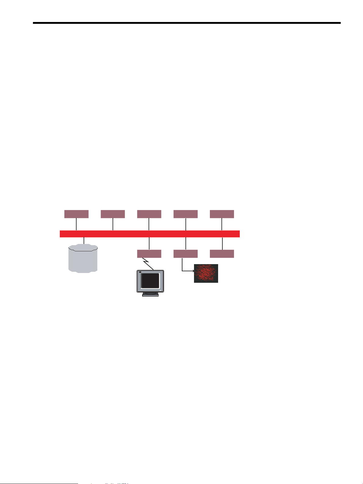
environment of customers as shown in Figure 1-1.
Figure 1-1 System View of a Computing Environment with Integrated SVA
High-speed networks make feasible the transfer of large amounts of data among the following:
• Individual users at their desktops, or logged into a cluster.
• The compute nodes, the visualization nodes, and local and remote display devices.
• Servers that are part of data storage farms.
A typical usage model for the type of system shown in Figure 1-1 has the following characteristics:
• A compute intensive application, for example, an automobile crash test simulation, runs on
the supercomputing compute nodes of the cluster.
• The large dataset generated on the compute nodes can be stored in the storage servers for
later retrieval, or directed in realtime for rendering on the SVA portion of the overall system.
• One or more users can log into the SVA concurrently, which allocates resources efficiently
to meet the rendering and display requirements of each user application.
• Users’ visualization applications use parallel programming techniques and visualization
middleware software to distribute their graphical rendering across the SVA nodes, each of
which in turn renders a portion of the output for the final image. Image data can be
apportioned by a master application to a set of visualization nodes for rendering.
• Each portion of the final image rendered by a visualization node is sent to a tile of a single
or multi-tile display. The complete image is available for display locally. The complete image
1.1 Where SVA Fits in the High Performance Computing Environment 13
Page 14
is also available for display remotely, but limited to single or two-tile output from a single
OpenGL
Graphics
User Application
Master Node
user interface
transfer simulation data
and drawing commands
display nodes
System Interconnect
Card
OpenGL
Graphics
Card
OpenGL
Graphics
Card
OpenGL
Graphics
Card
multi-tile display
render nodes
OpenGL
Graphics
Card
OpenGL
Graphics
Card
OpenGL
Graphics
Card
graphics card.
The SVA serves as a key unit in an integrated computing environment that displays the results
of generated data in locations where scientists and engineers can most effectively carry out
analyses individually or collaboratively.
1.2 SVA Clusters
This section gives a high-level description of a standalone SVA, that is, an HP Cluster Platform
system built to include visualization nodes. The SVA can also provide a visualization solution
that is fully integrated into an existing HP Cluster Platform system with compute and storage
components, as shown in Figure 1-1.
The SVA image-based approach works with a variety of visualization techniques, including
isosurface extraction and volume visualization. Such a graphics architecture combines the high
performance of clustersof rendering machines with the interactivity made possible by the speed,
scalability, and low latency of the cluster network.
HP SVA offers a graphics visualization solution that can be used by a variety of applications that
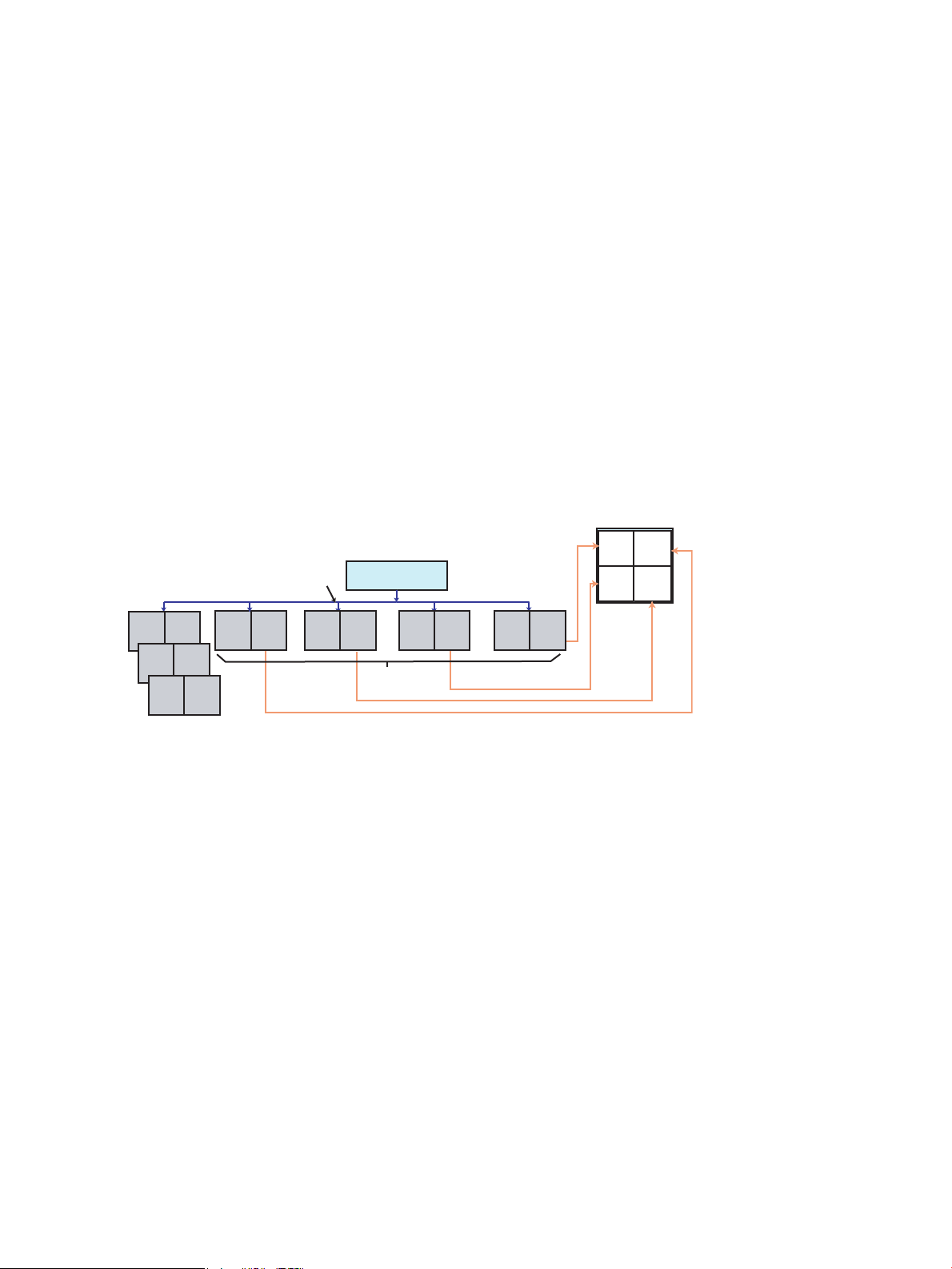
run on distributed computing systems; in this case, a cluster of Linux workstations. Figure 1-2
illustrates the makeup of a standalone SVA.
Figure 1-2 Standalone SVA Data Flow
14 Introduction
Key points of Figure 1-2 are the following:
• Industry standard workstations and servers with standard OpenGL 3D graphics cardsserve
as visualization nodes (render and display), and run clustering software and Linux. Use of
industry standard graphics cards lets the system take advantage of new generations of cards
as they become available.
• Depending on the design of the application, an application “master” can run the application
and the user interface for the application on a specified node.
• Display nodes transfer their rendered output to the display devices and can synchronize
multi-tile displays. A range of displays are supported at locations local and remote to the
SVA. A series of render nodes can also contribute composited images to the display nodes,
depending on the visualization application. The HP Parallel Compositing Library that ships
with SVA can help application developers accomplish parallel rendering. See the SVA Parallel
Compositing Reference Guide.
• The System Interconnect (SI) supports data transfer among visualization nodes. High-speed,
low-latency networks such as InfiniBand and Myrinet can be used for the SI to speed the
transfer of image data and drawing commands to the visualization nodes.
Each portion of an image is rendered on its visualization node as determined by the application
and the visualization middleware being used. For example, you can use Chromium or a
scenegraph application in conjunction with Distributed MultiHead X (DMX). The final images
are transmitted by the graphics cards in the display nodes to the display devices.
Page 15

Final images can also be transmitted to a remote workstation display over a network external to
the cluster. This lets users interact with applications running on the cluster from their offices.
Optionally, you can use HP Remote Graphics Software (RGS) or VirtualGL to accomplish this
more easily. See Chapter 6 for more information on both these packages.
Figure 1-2 also shows a master application node communicating with the other visualization
nodes over the SI. The SI carries file I/O and application communications; for example, MPI
traffic. The user interface for a visualization application can run on a master application node
and communicate with the visualization nodes over the SI, sending control information such as
changes in point of view, data, or OpenGL commands.
1.3 Displays
Display devices are not necessarily provided as part of the SVA. For example, your site can use
projector display systems or immersive displays provided by third party vendors.
Displays fall into a number of categories, including immersive CAVE displays, single monitors,
multiheaded monitors, large wall displays, multiheaded desktops, flat panels, and projector
displays used in theaters. SVA hardware and software deliver images to digital or analog standard
interfaces. The SVA depends on the graphics cards to drive the image output. This means the
wide range of display devices that the graphics cards support are available for use.
See Section 3.5 for more information.
1.4 SVA Functional Attributes
The key to SVA scalability and flexibility is its combination of cluster technology with high-speed
graphics cards and networks to transfer data. The SVA enables scaling up the number of nodes
working on a problem in parallel to handle larger dataset sizes, to increase frame rates, and to
display at higher image resolutions.
1.4.1 Scalability
There are a number of ways that applications can be designed and implemented to take advantage
of an SVA for effective scaling:
• Performance scaling: Render image data on separate nodes in the SVA. In effect, the work
is divided up among nodes working in parallel. Larger datasets can be accommodated by
more render nodes. The system design can scale from four to forty visualization nodes. This
count does not include the required head node.
The parallel attributes of the rendering pipeline removes a key performance bottleneck of
a conventional hardware accelerated graphics architecture, which feeds data sequentially
to a centralized pipeline.
In addition, the choice of a network that transmits data among the visualization nodes with
adequately low latency and high speed maintains interactive frame rates for delivery to the
display devices.
• Resolution scaling: Parallel rendering, combined with the parallel display of multiple tiles
makes such scaling possible. You can display high-resolution data and use large display
surfaces, including immersive displays and display walls.
In general, adding nodes to a dataset of fixed size provides good scaling up of the frame rate,
although speed-up is not linear because of the inevitable overhead due to portions of an
application's code that cannot be made parallel. However, a strength of SVA as a cluster
visualization platform is that scalability is nearly linear when the dataset size and node count
are both increased. For example, doubling the node count from four to eight makes it possible
to double the distributed dataset size with virtually no loss of frame rate. To achieve such gains
in frame rate, an application must be a true parallel application to efficiently distribute data and
to load balance across cluster nodes.
1.3 Displays 15
Page 16
1.4.2 Flexibility
Visualization
Libraries
(optional)
Applications
X Servers
HP XC Linux
Allocate
Launch
Initialize
Cleanup
SVA
Software
Utilities
OpenGL
Cluster Nodes and Displays
One of the most powerful attributes of the SVA is its flexibility, which makes it possible to apply
the SVA effectively to a wide range of technical problems. This flexibility derives from the
architectural characteristics of the SVA.
When the architectural characteristics of the SVA are integrated with an HP high performance
compute cluster (see Figure 1-1), you can select an optimal number of application or compute
nodes and match them with an appropriate number of render and display nodes. Visual
applications with high computation requirements can be distributed over the compute nodes
and the visualization nodes; thus the render nodes can double as compute nodes.
This flexibility is critical because visualization applications often need to perform intensive
computations to compute isosurfaces, streamlines, or particle traces. You can select application
nodes based on factors such as model size, and match them to the visualization nodes your
application needs to yield the desired performance and resolution.
1.5 Application Support
This section introduces software support for application developers. Chapter 3 contains more
information on the software tools available for application developers.
HP recognizes that a key capability of the SVA is to make it possible for serial applications to
run without extensive recoding. To that end, HP works with both commercial ISVs and the open
source community to ensure solutions are available for the SVA.
Figure 1-3 illustrates the layers of software support and their hierarchical interrelationships that
are part of the SVA. These include:
• Cluster management software (HP XC) and visualization resource management software
(SVA Software Utilities).
• Visualization toolkits and libraries.
• User and third-party visualization applications.
Figure 1-3 also shows the tasks carried out by the SVA Software Utilities (part of the Visualization
System Software (VSS)). These tasks — allocate, launch, initialize, cleanup — are aligned alongside
the software layers they impact.
Figure 1-3 Software Support for Application Development and Use
Visualization and graphics toolkits are provided by third party vendors and the open source
community. ISV applications and applications written by end users can run on the SVA, taking
16 Introduction
Page 17

full advantage of the various toolkits and libraries. The SVA uses standards such as OpenGL,
Linux, InfiniBand, and Gigabit Ethernet for portability and interoperability.
The HP Parallel Compositing Library that ships with SVA can help application developers
accomplish parallel rendering. See the SVA Parallel Compositing Reference Guide.
To achieve maximum performance scaling when running on the SVA, an application must be
parallel and distributed. There are two main pathways to this state: applications made parallel
by design and serial applications made parallel automatically through middleware libraries or
toolkits; for example, Chromium or other middleware.
1.5.1 OpenGL Applications
If your application is already parallel and distributed, you can use OpenGL directly.
Most visualization applications support OpenGL directly or through graphics toolkits.
Autoparallel toolkits such as Chromium, enable standard OpenGL applications to run on an
SVA with increased resolution, although without the performance advantages of a true parallel
application.
1.5.2 Scenegraph Applications
The SVA lets you take advantage of scenegraph applications available through scenegraph
middleware libraries and toolkits. The result is that the application is available on the SVA and
can take advantage of its parallel scalability features.
1.5 Application Support 17
Page 18

18
Page 19

2 SVA Architecture
This chapter gives a detailed look at the architecture of the HP Scalable Visualization Array
(SVA). It compares the SVA to other clusters and describes the flow of data within the cluster.
2.1 SVA as a Cluster
It is important to understand the cluster characteristics of the SVA. These characteristics have
implications for how SVA functions. They also affect how applications take advantage of cluster
features to achieve graphical performance and display goals.
2.1.1 Background on Linux Clusters
In the taxonomy of parallel computers, the SVA is most similar to a Beowulf class Linux cluster.
Beowulf clustershave many servers of the same type that communicate on high speed connections
such as channel bonded Ethernet. In this way, the cluster provides high performance for
applications capable of using parallel processing. This type of cluster can provide exceptional
computational performance.
A Beowulf cluster falls somewhere between the class of systems known as Massively Parallel
Processors (MPP) and a network of workstations (NOW). Examples of MPP systems include the
nCube, CM5, Convex SPP, Cray T3D, and Cray T3E. Beowulf clusters benefit from developments
in both these classes of architecture.
MPPs are typically larger and have a lower latency interconnect than a Beowulf cluster. However,
programmers on MPPs must take into account locality, load balancing, granularity, and
communication overheads to obtain the best performance. Even on shared memory machines,
many programmers develop programs that use message passing. Programs that do not require
fine-grain computation and communication can usually be ported and run effectively on a Linux
cluster.
Programming a NOW is usually an attempt to harvest unused cycles on an already-installed
base of workstations in a lab or on a campus. Programming in this environment requires
algorithms that are extremely tolerant of load balancing problems and large communication
latency. Any program that runs on a NOW runs at least as well on a cluster.
A Beowulf cluster is distinguished from a NOW by several subtle but significant characteristics.
These characteristics are shared by the SVA.
• Nodes in the cluster are dedicated to the cluster. This helps ease load balancing problems
because the performance of individual nodes is not subject to external factors.
• Because the System Interconnect (SI) is isolated from the external network, the network load
is determined only by the applications being run on the cluster. This eases problems
associated with unpredictable latency in NOWs.
• All nodes in the cluster are within the administrative jurisdiction of the cluster. For example,
the SI for the cluster is less visible to the outside world. Often, the only authentication needed
between processors is for system integrity. On a NOW, network security is an issue.
2.2 Architectural Design
The SVA derives its most powerful attributes from its architectural design, which consists of a
cluster of visualization nodes, high-speed interconnects, and advanced graphics cards.
SVA runs parallel visualization applications efficiently. The SVA also is an integral part of the
HP Cluster Platform and storage (HP Scalable File Share) solutions. To accomplish this, the SVA
architecture extends the HP Cluster Platform architecture with the addition of visualization
nodes, which you can use as specialized compute nodes. Further, an SVA can be made up entirely
of visualization nodes, or it can share an interconnect with compute nodes and a storage system.
2.1 SVA as a Cluster 19
Page 20

Thus, the SVA provides the HP Cluster Platform with a visualization component for those
applications that require visualization in addition to computation.
The following sections describe the components that make up an HP Cluster Platform, followed
by those tasks and components that are unique to an SVA.
2.2.1 Components of the HP Cluster Platform
Because the SVA is an extension of the HP Cluster Platform, you can begin by understanding its
base components without any visualization nodes. The following are the key architectural
components of an HP Cluster Platform system without visualization nodes:
Compute Nodes and
Administrative/Service Nodes
System Interconnect (SI) A high-bandwidth, low-latency network which connects
Administrative Network An Administrative Network connects all nodes in the
Linux The nodes of the cluster run a derivative of 64-bit Red Hat®
The compute cluster consists of compute nodes and
administrative or service nodes. Parallel applications are
allocated exclusive use of the compute nodes on which
they run. The other nodes provide administration, software
installation, remote login, file I/O, external network access,
and so on. These nodes are shared by multiple jobs, and
are not allocated to individual jobs. One such node is
designated as the head node, which is used for
administration and connects to the external network.
all nodes. This supports communication among the
compute nodes (for example, MPI and sockets) and file
I/O between compute nodes and a shared file system.
cluster. In an HP XC compute cluster, this consists of two
branches, the Administrative Network and the Console
Network. This private local Ethernet network runs TCP/IP.
The Administrative Network is Gigabit Ethernet (GigE);
the Console Network is 10/100 BaseT. (Because
visualization nodes do not support console functions,
visualization nodes are not connected to a console branch.)
Enterprise Linux Advanced Server.
Note:
All nodes must attach to two networks using different ports, one for the SI and one for the
Administrative Network.
2.2.2 Main Visualization Cluster Tasks
The SVA has a number of tasks that are unique to a visualization-capable cluster. It accomplishes
these tasks using a set of unique node types that differ in their hardware configurations, and so
are capable of different functional tasks. The main tasks are as follows:
Render images. A node must have a graphics card to render images. A
Display images. The final output of a visualization application is a complete
20 SVA Architecture
visualization job uses multiple nodes to render image data
in parallel. A render node typically communicates over
the SI with other render and display nodes to composite
and display images.
displayed image that is the result of the parallel rendering
that takes place during an application job. To make this
possible, a display node must contain a graphics card
connected toa display device. The display can show images
integrated with the application user interface, or full screen
Page 21

Remote images. The SVA also supports the transmission of a complete
Integrate an application user
interface.
2.2.3 Components of an SVA
The main tasks described in Section 2.2.2 are supported by two types of visualization nodes,
which differ in their configuration and in the tasks they carry out. The two nodes types can carry
out multiple tasks. These node types are unique to the SVA configuration and extend HP compute
clusters to support visualization functions. See Chapter 3 for detailed information on the hardware
configurations of these node types.
Display Nodes Display nodes carry out the display task. Typically, a displaynode contains
one or two graphics cards, each connected to its display device(s). The
output of each graphics card port (two ports per card) on a display node
can be sent to a display device. Final output can be a single tile or a partial
image in the form of a single tile, which is part of an aggregate multi-tile
display.
The SVA supports up to eight display nodes in a Display Surface. The
display nodes in your cluster can drive one or two display devices in the
case of the xw8200, xw8400, DL140 G3, and DL145 G3 nodes, and one to
four display devices in the case of xw9300 and xw9400 nodes. See the SVA
System Administration Guide for more information on setting up display
nodes, displays, and Display Surfaces.
images. The output can be a complete display or one tile
of an aggregate display.
image to a system external to the cluster over an external
network for remote viewing; for example, to an office
workstation outside the lab. A node with a port connected
to the external network is recommended. Alternatively,
you can connect to the external network by routing through
another cluster node with such a port.
An application user interface (UI) usually runs on a cluster
node. The UI typically controls the parts of the distributed
application running on other nodes. A node that provides
users with access to the UI can have an attached keyboard,
mouse, and monitor for user interaction. Alternatively, the
node can export the application UI to an external node
using the X protocol or using the HP Remote Graphics
Software (RGS) or VirtualGL. If you use RGS or VirtualGL,
a port connected to the external network is recommended.
Render Nodes Render nodes render images, as do display nodes. However, render nodes
are not connected directly to display devices. Typically, render nodes are
used by visualization applications that composite images. Render nodes
render a part of the final image. These sub-images are combined with
sub-images from other nodes. The composited image data is transferred
to another render node, or to a display node to be routed to a display device.
Render nodes are industry standard workstations or servers with standard
OpenGL 3D graphics cards.
Both types of nodes can perform UI and remote graphics functions. When nodes are allocated
to a job, the job typically requires specific display nodes that correspond to the display devices
intended for use. Typically, there is no requirement for specific render nodes.
2.2.4 Configuration Flexibility
The SVA supports several different configurations and uses. These include:
2.2 Architectural Design 21
Page 22

• Multiple displays with different resolutions.
OpenGL
Graphics
User Application
Master Node
user interface
transfer simulation data
and drawing commands
display nodes
System Interconnect
Card
OpenGL
Graphics
Card
OpenGL
Graphics
Card
OpenGL
Graphics
Card
multi-tile display
render nodes
OpenGL
Graphics
Card
OpenGL
Graphics
Card
OpenGL
Graphics
Card
• Use of a variable number of display and render nodes to solve the computational and
rendering requirements of an application.
• Bounded configuration designed for a single user.
• Larger, modular, expandable systems designed for one or more concurrent users.
See Chapter 3 for more information on the physical configurations of the SVA.
2.3 SVA Operation
This section describes a common way data flows through an SVA.
2.3.1 Cluster Data Flow
Figure 2-1 shows a high-level view of the basic components of an SVA.
Figure 2-1 SVA Data Flow Overview
A common usage scenario includes a master application node that runs the controlling logic of
an application, processes the 3D data, and updates the virtual display or scene in the case of
scenegraph applications. The master node typically does no rendering. Because it transmits data
changes to other visualization nodes, it must be able to communicate with these nodes using the
cluster SI. The SI is the fastest network available to the SVA and is the best choice for internode
communication when performance is important.
A different scenario does not use a master application node. Instead, an application relies on
Distributed Multi-Head X (DMX) to distribute the display output to multiple nodes and displays.
It does this by controlling the back-end X Servers running on each of the display nodes. Partial
images routed to individual display devices are assembled and displayed as a single virtual
image.
Other scenarios arise depending on the application and the capabilities of visualization
middleware running on the SVA. For example, several render nodes can carry out rendering
and compositing tasks. The render nodes can rely on middleware software to handle the
compositing of any partial images. The image data then flows to a display node before being
sent to a display device or remote node, for example; a desktop display outside the SVA.
See Chapter 6 for other usage scenarios.
2.3.2 File Access
Visualization applications typically read data from files in response to user input. For example,
after starting an application, you specify a data file to open and load. Without exiting the
application, you can select additional data files to open and load, replacing or adding to the data
already loaded. Much visualized data is static rather than time-varying. When visualizing
time-varying data, the application must read and cache multiple time steps. The application may
22 SVA Architecture
not be able to visualize the data as it is being read. Each time step may need to be analyzed and
Page 23

features extracted based on application settings. The application then caches the results of the
analysis or rendering to display an animation of the time steps.
Although parallel visualization is a relatively new approach, some file access patterns that
applications use include the following:
• Master portion of the application reads data from files and distributes data to visualization
nodes using the SI.
• Visualization nodes all read data from the same files.
• Visualization nodes all read data from different files.
• Master writes data; for example, to save an animation sequence.
Dataset sizes can range from less than 1GB to more than 100GB. Some examples include seismic
datasets that are 1GB to 128GB, and medical datasets that are 1GB to 50GB.
Applications access files using HP Scalable File Share (SFS) or NFS. When visualization nodes
are integrated into a cluster with HP SFS, they access this file system using the SI. When HP SFS
is in a separate cluster and not accessible by the SI, access is with GigE.
See the SVA System Administration Guide for more information.
2.3 SVA Operation 23
Page 24

24
Page 25

3 SVA Hardware and Software
This chapter provides information on the hardware and software that make up the SVA. It is a
useful reference for anyone involved in managing the SVA. It is also useful for anyone who
wants to understand the hardware that makes up the SVA and the software that is installed on
it.
The SVA combines commodity hardware components with software that include the following:
• A cluster of Intel EM64T or AMD-64 Opteron HP workstations and servers as visualization
nodes.
• A range of graphics cards that varies by workstation or server: NVIDIA® Quadro® FX 1500
(DL140 G3, DL145 G3), NVIDIA Quadro FX 3450 (xw8200, xw9300), NVIDIA Quadro FX
3500 (xw8400,xw9400, DL140 G3, DL145 G3), NVIDIA Quadro FX 4500 with optional G-sync
or hardware SLI (xw8200, xw8400, xw9300, xw9400), or NVIDIA Quadro FX 5500 with
optional G-sync or hardware SLI (xw8400, xw9400).
• InfiniBand, Gigabit Ethernet (GigE), or Myrinet system interconnects.
• Third-party software tools and libraries.
• Custom and enhanced software tools.
3.1 Hardware Component Summary
You can use the SVA with a variety of applications that run on distributed computing systems;
in this case, a cluster of Linux workstations. The SVA is a specialized version of the HP Cluster
Platform systems.
There are two SVA physical configurations:
Bounded Configuration Contains only visualization nodes and is limited in size to
four to seventeen workstations plus a workstation or server
head node. This configuration is based on racked
component building blocks, namely the Utility
Visualization Block (UVB) and the Visualization Building
Block (VBB).
The bounded configuration serves as a standalone
visualization cluster and is not integrated with compute
nodes. The bounded configuration meets the need for
relatively small, personal use clusters consisting of only
four workstations. When expanded to seventeen nodes,
such a cluster can be a visualization-specific, multi-user
system capable of driving a large display wall. Although
designed as a standalone cluster, it can be connected to a
larger HP XC cluster using external GigE connections. This
level of inter-cluster integration supports communication
with a compute cluster and data retrieval from a file share,
such as an HP Scalable File Share (SFS).
Modular Packaging Configuration This configuration has two or more racks as needed to
contain from four to ninety-five workstations or servers,
along with a server head node. All servers and
workstations must have the same CPU type (EM64T or
Opteron). This configuration is based on HP Cluster
Platform building blocks, namely the Visualization
Building Block (VBB) and the Utility Building Block (UBB).
It can be exclusively visualization nodes or be combined
with compute nodes as part of an integrated HP Cluster
Platform system. When integrated into a larger Cluster
3.1 Hardware Component Summary 25
Page 26

The two SVA physical configurations are built using one or more of three types of cluster building
blocks. Each building block uses a single rack.
Utility Visualization Block (UVB) Base utility unit of a Bounded Configuration. It contains
Utility Building Block (UBB) Base utility unit of a Modular Packaging Configuration. It
Visualization Building Block (VBB) Rack of visualization nodes that can be added to either
3.2 Bounded Configuration
A Bounded Configuration is built from the UVB and VBB rack systems. It has the following
components as summarized in Chapter 2:
• Render and Display nodes.
Workstations: xw8200, xw8400, xw9300, xw9400.
Platform system, the visualization nodes can use a high
speed system interconnect to load data from an HP SFS.
network switches, PDU, workstations (xw8200, xw8400,
xw9300, or xw9400), head node (xw8200, xw8400,xw9300,
xw9400, DL380 G4, or DL385 G4), and an optional KVM.
contains network switches, PDU, head node (DL380 G4,
or DL385 G4), and an optional KVM.
base unit to create a Bounded Configuration or a Modular
Packaging Configuration. It contains PDU, workstation or
server nodes, and an optional KVM.
• Head node.
Workstations: xw8200, xw8400, xw9300, xw9400, or servers: DL380 G4 and DL385 G4.
• Optional KVM.
• System Interconnect and Administrative Network (found in HP Cluster Platform systems,
and thus not unique to the SVA).
The head node is a typical node type found in HP Cluster Platform systems.
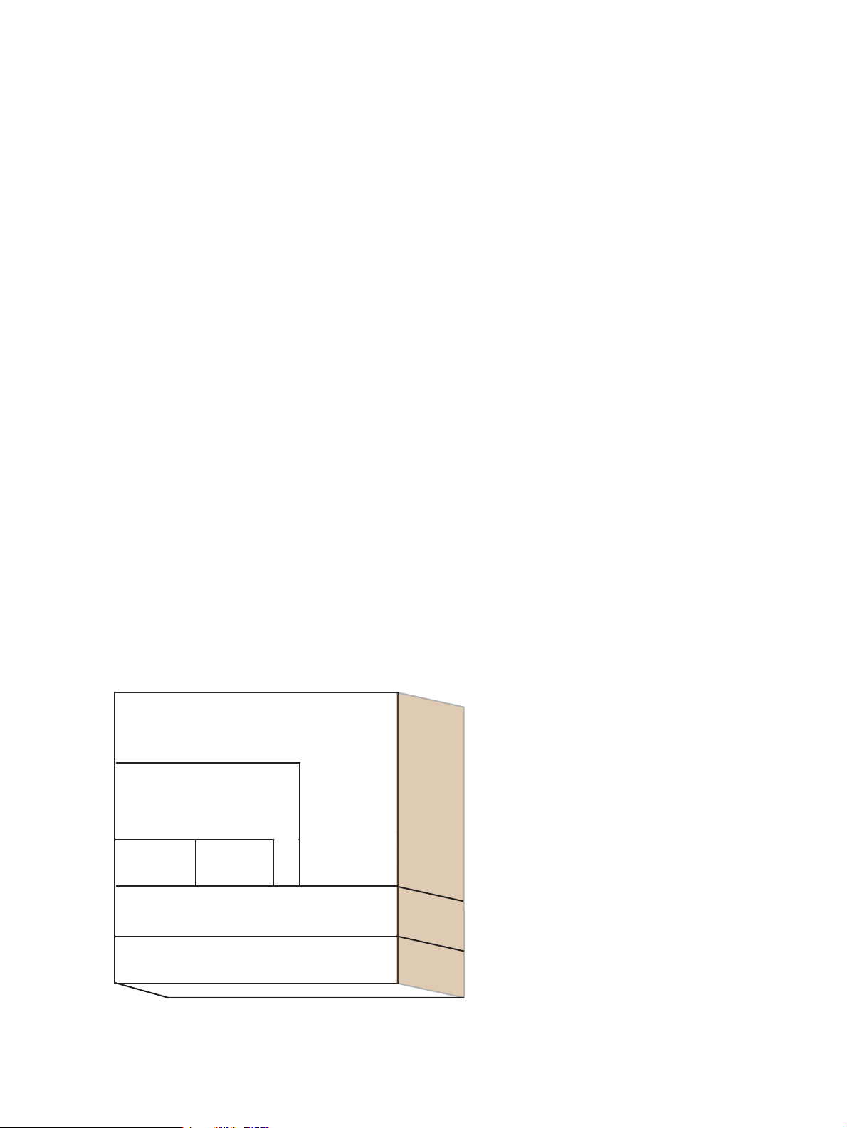
Figure 3-1 illustrates a sample Bounded Configuration. The UVB contains the network switches,
PDU, five visualization nodes, and the head node. The visualization nodes support a 2x2 multi-tile
display. Additional VBBs can be added to this configuration, with up to eight workstations in
each rack.
26 SVA Hardware and Software
Page 27

Figure 3-1 Sample SVA Bounded Configuration
GigE
External Node
Display
Devices
Base Rack (UVB)
3.3 Modular Packaging Configuration
A Modular Packaging Configuration is built from the UBB and VBB rack systems. It has the
following components as summarized in Chapter 2:
• Render and Display nodes.
Workstations: xw8200, xw8400, xw9300, xw9400, or servers: DL140 G3 or DL145 G3 .
• Head node.
DL380 G4 or a DL385 G4 server.
• Optional KVM.
• System Interconnect and Administrative Network (found in HP Cluster Platform systems,
and thus not unique to the SVA).
The head node is a typical node type found in HP Cluster Platform systems. The server head
node must have the same architecture as any workstations in the cluster.
3.4 Network Configurations
This section describes the different networks used in the SVA.
3.4.1 System Interconnect (SI)
3.4.2 Administrative Network Connections
The SI for visualization nodes can be GigE, InfiniBand, or Myrinet. When the visualization nodes
are integrated with compute nodes, the choice of SI is usually determined by the requirements
of the compute nodes.
A GigE interconnect serves as the Administrative Network to control the operation of the cluster
(for example, boot, shutdown, restart) and to control the running parts of a distributed application
(for example, launching and stopping processes).
The SVA adds visualization capability to an HP XC cluster; therefore, the Administrative Network
is implemented with the logical configuration defined by the HP XC and Cluster Platform
architectures. However, the physical implementation differs.
3.3 Modular Packaging Configuration 27
Page 28

The management switches are collected together in one rack. SVA nodes connect to branch
switches in the Administrative Network. SVA nodes do not connect to the console branch.
Nodes connect to the switches according to the Cluster Platform Administrative Network
connections for HP XC. Display and render node types are typically grouped together.
3.5 Display Devices
SVA supports a wide range of displays and configurations, including single displays, tiled
displays in walls, and immersive CAVE environments using projector systems. SVA relies on
the display capabilities of the graphics cards in the display nodes. This means that the SVA lets
you use the wide range of display devices that are supported by the graphics card.
Depending on the demands of the display devices, you can use digital or analog output. The
aggregate resolution of these displays can range from 10s to 100s of megapixels.
The SVA supports up to eight display nodes1in a Display Surface. The display nodes in your
cluster can drive one or two display devices in the case of the xw8200, xw8400, DL140 G3, and
DL145 G3 nodes, and one to four display devices in the case of xw9300 or xw9400 nodes. (Note
that the xw8400 can be used to drive four display devices when ordered and configured on an
exception basis.) This means that you can drive a maximum of 32 display devices using eight
xw9300 or xw9400 nodes.
Theoretically, SVA technology can scale to arbitrarily large displays. Realistically, the bandwidth
of the network delivering subparts of the image to various nodes, and the resolution of display
devices are limiting factors. You can create large displays by arranging a grid of smaller displays.
See the SVA System Administration Guide for more information on setting up display nodes and
devices.
3.6 SVA Software Summary
The SVA combines third party software tools and libraries with custom and enhanced software
tools and libraries. SVA software must be installed and run on each visualization node as well
as the head node of a valid cluster configuration, such as an HP Cluster Platform 3000 or HP
Cluster Platform 4000, properly configured for HP XC System Software with the SVA option.
This section describes the following software categories:
• Linux Operating System.
• HP XC clustering software.
• Additional system software.
Figure 3-2 illustrates the various software categories and their hierarchical interrelationships, as
well as the tasks carried out by the utilities provided by HP Visualization System Software (VSS).
These tasks — allocate, launch, initialize, cleanup — are aligned alongside the software categories
they impact.
1. More display nodes may be supported on an exceptional basis.
28 SVA Hardware and Software
Page 29

Figure 3-2 Software Hierarchy in the SVA
Visualization
Libraries
(optional)
Applications
X Servers
HP XC Linux
Allocate
Launch
Initialize
Cleanup
SVA
Software
Utilities
OpenGL
Cluster Nodes and Displays
3.6.1 Linux Operating System
The SVA software is layered on top of HP XC System Software Version 3.2, a clustering Linux
distribution compatible with Red Hat Enterprise Linux Advanced Server V4.0 Update 3. The
kernel version is V2.6.9–x.
See Section 3.6.2.
The windowing system used by Red Hat is the X.Org windowing system.
Table 3-1 summarizes the main operating system components as well as the low-level drivers.
Table 3-1 Operating System and Driver Components
Base Operating System
Red Hat Enterprise Linux Advanced Server
V4.0 Update 3.
www.redhat.com
http://docs.hp.com/en/highperfcomp.html
X.Org Windowing System.
X.Org Foundation: www.x.org
3.6.2 HP XC Clustering Software
Low-Level Drivers
Linux driver for the supported NVIDIA
Quadro FX graphics cards.
The SVA runs HP XC System Software Version 3.2 clustering software. The SVA uses HP XC for
the following key system management tasks:
• Installing and reinstalling a uniform set of software on visualization nodes.
• Booting and shutting down the cluster.
• Managing user accounts and user directories across the cluster.
NotesComponent
HP XC Linux is compatible with this version of Red Hat Enterprise
Linux; however, it is built by HP and does not contain all the
components distributed by Red Hat.
Clustering software.HP XC System Software Version 3.2.
Official Windowing System of the X.Org Foundation that is also
included as part of the standard Red Hat distribution.
Device driver for the graphics cardsprovided by NVIDIA Corporation.
Qualified by HP WGBU group.
InfiniBand, GigE, and Myrinet are supported.Driver for selected high-speed interconnect.
3.6 SVA Software Summary 29
Page 30

• Naming each of the nodes in the cluster and determining which nodes are up and running.
• Serializing application use of the cluster.
For more information on HP XC, consult the HP XC documentation set at the following Web
site:
http://docs.hp.com/en/highperfcomp.html
Table 3-2 summarizes the software components that are provided by the HP XC operating system
that relate to the SVA.
Table 3-2 HP XC System Components Relevant to SVA Operation
NotesComponent
Simple Linux Utility for Resource
Management (SLURM)
Platform Load Sharing Facility for High
Performance Computing (LSF HPC)
3.6.3 Additional System Software
The SVA Software Kit provides software focused on making the job of developing and running
visualization applications easier. This section summarizes additional system software of interest
related to the SVA, as well as where to get information on packages or applications. The main
categories of additional system software include:
• Main software components provided by HP (Table 3-3).
• Main software components provided by third parties (Table 3-4).
• Application development tools available on the SVA (Table 3-5).
A resource manager for Linux clusters. Used to set up visualization
sessions and launch visualization jobs. Preferred allocation utility of
HP XC.
Layered on top of SLURM to provide high-level scheduling services
for the HP XC system software user. LSF can be used in parallel with
SVA job launching techniques that rely on SLURM.
System file replication used to install cluster nodes.SystemImager
A parallel distributed shell that replaces rsh and ssh.pdsh
Message Passing Interface.HP-MPI
High performance file system (optional).HP Scalable File Share (HP SFS)
License management.FlexLM®
Table 3-3 HP SVA System Software
Visualization System Software (VSS)
See the SVA Visualization System Software Reference
Guide in the SVA Documentation Library.
HP Parallel Compositing Reference Guide
See the SVA Parallel Compositing Library Reference
Guide in the SVA Documentation Library.
HP Remote Graphics Software
http://www.hp.com/workstations/software/remote/
30 SVA Hardware and Software
DescriptionSoftware
Collection of various categories, including:
• Data Access Functions that permit an application to access
and use the Configuration Data Files for job allocation and
launch.
• Command syntax for job launch scripts commands.
Shipped with SVA, the HP Parallel Compositing Library helps
application developers easily create parallel rendering
applications.
Transmits2D and3D images across standard computer networks
to remote users.
(optional purchase)
Page 31

Table 3-4 Third Party System Software
http://www.opengl.org/
DescriptionSoftware
Primary interface programmers use to create images.OpenGL
OpenGL Utility library (GLU)
freeglut
http://freeglut.sourceforge.net/
OpenMotif
Distributed MultiHead X (DMX)
http://dmx.sourceforge.net/
Chromium
http://chromium.sourceforge.net/
Table 3-5 Application Development Tools
DescriptionSoftware
Included as part of the HP XC distribution.Default GNU C and C++ compilers and
run-time
Contains routines that build on the lower level OpenGL library
to perform such tasks as setting up matrices for specific viewing
orientations and projections, performing polygon tessellation,
and rendering surfaces.
This library masks a number of the operating system specific
calls for creating windows and managing input devices.
Royalty-free version of Motif®, the industry standard graphical
user interface. It provides users with the industry's most widely
used environment for standardizing application presentation on
a wide range of platforms.
An open source application that provides a proxy X Server that
distributes its display over multiple X Servers.
X Server available as part of the Red Hat distribution.X Server (X.Org)
A system for interactive rendering on clusters of graphics
workstations.
gdb GNU debugger
Perl, Tcl/tk, Python
Included as part of the HP XC distribution.
Scripting tools available as part of the HP XC distribution.
64 bit Linux applications are supported on SVA systems; 34 bit applications may run if their
providers have validated them to run on 64 bit Linux systems. You may find that you need to
install additional libraries. You may also find that certain libraries, for example, MPI, don't work
for particular hardware configurations.
3.6 SVA Software Summary 31
Page 32

32
Page 33

4 Quick Start
This chapter lets you quickly try some of the sample applications on the SVA Kit. Details on
using scripts are provided in other chapters of this HP SVA User's Guide and other documents
in the HP SVA Documentation Library.
4.1 Typical Uses of SVA
SVA has three primary usage scenarios as described in detail in Chapter 6.
• A workstation application that is launched remotely to use only a single node in the SVA.
• An application that uses render and display capabilities of the SVA (for example, ParaView).
• A workstation application that uses Chromium software and DMX to display on multiple
tiles using the SVA.
4.2 Configuring Displays for Use with SVA
There are several steps to getting the cluster display devices working, particularly in the case of
complex display systems, including stereo systems. These steps are typically done by the system
manager for the cluster.
• Physically set up display nodes and display devices.
Plan how you want the display devices arranged, and how you want to use your display
nodes to drive your display devices. It also involves cabling the display nodes to the display
devices.
• Configure Display Nodes and Display Surfaces.
This task involves using two SVA tools:
— Node Configuration Tool: Use this tool to define the tile orientation for individual
display nodes.
When the cluster is built by HP Manufacturing, display nodes are configured with a
default of having a single display device per display node. If a cluster uses single display
nodes to drive multiple display devices (a one to several relationship), you need to use
the Node Configuration Tool. The output of a single display node is defined as a display
block. The Node Configuration Tool is used when a display node drives more than one
tile, that is, uses one or two graphics cards and/or multiple ports on a card. A tile is
assumed to be the image output from a single port of a graphics card.
The tool also lets you change the role of a node, for example, from render to display
and vice versa.
— Display Surface Configuration Tool: Use this tool to assemble the output of one or more
display nodes in a particular spatial orientation. This orientation is needed to define
Display Surfaces.
One or more display blocks are assembled into a Display Surface using the Display
Surface Configuration Tool.
4.1 Typical Uses of SVA 33
Page 34

TIP: See the HP SVA System Administration Guide for detailed information on how to define
Display Surfaces, including a recommended incremental series of steps for configuring SVA
for your displays.
• Verify and possibly modify supported resolutions, display modelines, and refresh rates.
This step is likely to be required for stereo displays and more exotic mono displays. Typical
desktop display devices (monitors and flat panels) are supported by default by SVA.
This topic is covered in detail in the HP SVA System Administration Guide. Note the following:
— You should not edit the standard X Configuration File (xorg.conf) on individual
visualization nodes. SVA creates its own set of SVA X Configuration Files during
installation. Only these are used by SVA when you launch a job.
— The SVA X Configuration Files support most desktop-style displays (flat panels and
monitors) without any changes. More exotic display devices (for example, projector
systems, extremely high-resolution devices, or stereo displays) require changes to the
settings in the SVA X Configuration Files.
— In the case of such exotic displays, you will need information from the display vendor,
namely, resolution, refresh rate, and modeline settings. Consult your display vendor
documentation.
— Use the display information to edit the settings in the SVA Monitor Properties Files.
After any edits, you need to regenerate the SVA X Configuration Files on all the nodes.
This process of editing and regenerating is detailed in the HP SVA System Administration
Guide.
4.3 Run a Test Application
Once you reach the point that the hardware is installed properly and the Display Surfaces are
defined, you can run a sample application to get a feel for how the cluster works. There are
several tasks that help familiarize you with the cluster:
• Set up how you want to control an application.
• Use an SVA launch script with a sample application. We recommend the
sva_chromium_dmx.sh script with the city application in interactive and then batch
mode.
• Run an application remotely using HP Remote Graphics Software (HP RGS). (HP RGS is an
optional purchase that may not be available on your cluster.) VirtualGL is an alternative
package to HP RGS for remote viewing.
See Chapter 5 for more detail on launch scripts. See Chapter 6 for more information on how to
use HP RGS and VirtualGL and their accompanying scripts.
4.3.1 Set Up Control for an Application
You have several ways to control an application (that is, provide mouse and keyboard input):
• Use a keyboard, mouse, and monitor plugged directly into the node running the application.
Note that the node that runs the application is determined by the SVA_EXECUTION_HOST
as described in Section 4.3.3.
• Use a console other than one connected directly to the node running the application. For
example, this could be the console connected to the head node. Use a KVM to switch to the
node running the application.
• Use HP Remote Graphics Software (HP RGS) or VirtualGL to control the application from
a node remote from the cluster.
34 Quick Start
Page 35

• In the case of third-party applications, for example, ParaView and EnSight, there is a separate
user interface whose location is determined by setting the DISPLAY environment variable
before you run the application.
• In the specific case of the SVA sva_chromium_dmx.sh script only: Use the -i option or
set the DISPLAY environment variable to specify the node from which you want to provide
input.
KVM/RKM Use:
If you are using a KVM or RKM to control your application, it does not necessarily display the
image as shown on a large multi-tile display. This is because the KVM/RKM cannot support such
a high resolution. The keyboard and mouse continue to work and you should be able to see the
cursor move on the large display as you use the mouse. Options for viewing and controlling a
large display are described in Section 4.3.2.
TIP: You may choose to use the --local option with the sva_paraview.sh script. The main
advantage of using this option is to have the application GUI visible on your current machine,
for example, the head node. See Section 5.4 for details on how to do this.
4.3.2 Launch an Application in Interactive Mode
Interactive mode lets you launch and terminate the application without re-allocating cluster
nodes to the job.
Before you launch an application in interactive mode, for example, with the Chromium-DMX
script, you need to specify the node from which you intend to provide input to the application
and on which you want to display the DMX Console Window. This window lets you view and
interact with multiple tiles on your console display. You do this by defining the DISPLAY
environment variable, for example:
% export DISPLAY node:0.0
Alternatively, you can specify the input node on the command line. Use the -i
input-x-display flag to the sva_chromium_dmx.sh script to force DMX to display the
DMX Console Window on the input-node (whatever you specify). Then use the DMX Console
Window to control the large display.
Use a command similar to the following to launch an interactive session:
% sva_chromium_dmx.sh -I -d YOUR_DISPLAY_SURFACE -i YOUR_INPUT_NODE:0.0
In the specific case of OpenGL applications, you use the Chromium/DMX script again from the
terminal window to run it. For example:
% sva_chromium_dmx.sh "city"
Note the following:
• You can launch the application from any node; the head node is a good location because
you can do other things from here as well as control the application. However, the Display
Surface definition determines the node on which the application runs by means of the
SVA_EXECUTION_HOST Configuration Data tag. Any image that you see is from the
SVA_EXECUTION_HOST node — not necessarily the console node. See the Section 6.3.4 and
the SVA System Administration Guide for more information on how this works.
• You need to substitute a previously defined Display Surface name that is site-specific for
YOUR_DISPLAY_SURFACE. (See the SVA System Administration Guide for information on
defining Display Surfaces.)
4.3 Run a Test Application 35
Page 36

• You need to substitute the name of the site-specific input node for YOUR_INPUT_NODE.
• The city application is shipped with the SVA kit and is already on your PATH. It is a good
application for seeing that the image is properly aligned among the individual tiles of a
multi-tile display.
• It is possible that you do not see any images on the input node's monitor; it could appear
blank. This is because the graphics card only supports one resolution at a time. If the
resolution of your large display is unsupported on the RKM, KVM, or console monitor, you
will see a blank screen on the input node. However, the keyboard and mouse continue to
work. For example, in the case of a KVM or RKM, you can use the arrow keys to switch
among nodes.
There are several options at this point:
— Continue to use the mouse and keyboard by referring to the large display itself for
feedback.
— Use a console monitor with a supported resolution.
— Specify the head node as the input node. DMX displays the DMX Console Window.
This does provide limited visual feedback on the head node for control of the large
display image. It also lets you do other work, such as launch another terminal window.
• You can start, stop, and restart an application to make it easier to test and debug.
See Chapter 5 for more detail on launching interactive jobs.
4.3.3 Launch an Application in Batch Mode
The following type of command launches the city application on a Display Surface called
YOUR_DISPLAY_SURFACE.
% sva_chromium_dmx.sh -d YOUR_DISPLAY_SURFACE "city"
Note the following:
• You can launch the application from any node; the head node is a good location. However,
the Display Surface definition determines the node on which the application runs by means
of the SVA_EXECUTION_HOST Configuration Data tag. Any image that you see is from the
SVA_EXECUTION_HOST node — not necessarily the console node. See Section 6.3.4 and the
SVA System Administration Guide for more information on how this works.
• You need to substitute a previously defined Display Surface name that is site-specific for
YOUR_DISPLAY_SURFACE. (See the SVA System Administration Guide for information on
defining Display Surfaces.)
• The city application is shipped with the kit and is already on your PATH. It is a good
application for seeing that the image is properly aligned among the individual tiles of a
multi-tile display.
4.3.4 Run an Application Using HP RGS
If your cluster has HP RGS installed (an optional purchase), you can launch and view an
application on a remote desktop, that is, one external to the cluster. You need to have the HP
RGS Receiver installed in your remote desktop before you can try this. See your system
administrator for help on installing the HP RGS Receiver.
SVA supports connecting to RGS from visualization nodes or the head node. These nodes must
have an external NIC and have the RGS Sender installed. Notethat during the cluster_config
process, the system administrator configures the SVA to identify remote-capable nodes.
Once you have the HP RGS Receiver installed on your desktop, follow these steps to start an
interactive session:
1. Login to the head node of the cluster from your desktop.
2. Enter the command:
36 Quick Start
Page 37

% sva_remote.sh -I
(Note that problems sometimes occur running the script or logging into the Linux GUI.
Check your login file for incompatible settings.)
3. HP RGS displays the name of the node it is connecting to on the cluster. Make a note of the
name.
4. Immediately start the RGS Receiver application on your desktop. It's helpful to have an icon
available for this.
5. Enter the name of the connected sender node into the Receiver window. Click on the Go
button in the Receiver window.
6. Enter your cluster username and password successively into the resulting login window.
7. Enter your username and password into the Linux Desktop.
8. Open a terminal window using MB3.
9. Enter the application command, for example, city or atlantis, at the command line. You
could also use one of the SVA launch scripts, for example, sva_paraview.sh with the
--local option. See Section 5.4 for more information.
10. Enter q or esc to exit application.
4.3 Run a Test Application 37
Page 38

38
Page 39

5 Setting Up and Running a Visualization Session
This chapter explains how to run visualization applications on the SVA. A visualization session
relies primarily on HP XC utilities to do the underlying work; however, you can avoid manually
using the underlying utilities by means of job launch scripts and associated templates provided
by the SVA kit.
For details on HP XC utilities, see the HP XC system documentation.
5.1 Configuration Data Files
This section provides an overview of the Configuration Data Files at a level applicable to all
users of the SVA. For details on the content and syntax of all the Configuration Data Files and
how to modify them, see the SVA System Administration Guide.
Configuration Data Files provide specific information about the system configuration of an SVA.
Site Configuration File details are mainly of interest to the system administrator who manages
and configures the cluster. However, the User Configuration File is likely to be of particular
interest to regular users of the SVA. All visualization sessions that you initiate to run your
application depend on input from the Configuration Data Files.
The Configuration Data Files contain important information on a visualization job session. For
example, they can specify the default applications available (such as, DMX or HP RGS), host
names, default resolution, node roles (render, display, compute, gpu number), and Display
Surface names,associated nodes, and default resolution. (A Display Surface is a named assemblage
of display nodes and their associated display devices, including the physical orientation of the
display devices relative to one another.)
There are three Configuration Data Files, which can interact to provide input when you start a
visualization session:
• Site Configuration File.
This file contains the default system settings and Display Surface definitions. It is generated
initially by HP (and a site administrator ifnecessary) using the svaconfigure utility when
the cluster software is installed. Only root users can change this file. This file is named
/hptc_cluster/sva/etc/sva.conf.
• User Configuration File.
Of particular interest to regular users of the SVA, this file lets you override some of the job
preferences specified in the Site Configuration File. This file is named
...~/sva_<cluster_name>.conf.
• Job Settings File.
Job data is defined at job allocation time from options specified to the job launch scripts and
from data access calls embedded in the script. The Job Settings File is named
/hptc_cluster/sva/job/<id>.conf. This file has a life span equal to that of the job.
Because the three files overlap in several (but not all) of their settings, a hierarchy exists for the
use of values specified from the command line and in more than one file. The prioritized order
of use of tag values during a job is as follows:
1. Command line options.
2. Job Settings File.
3. User Configuration File.
4. Any Display Surface values defined in the Display Surface declaration section of the Site
Configuration File, for example, SVA_TILE_GEOMETRY.
5. Site Configuration File.
5.1 Configuration Data Files 39
Page 40

5.2 Running an Application Using Scripts
Typically, you encapsulate the various commands needed to run applications using a script file.
This speeds the process of running the application, given the likelihood that this is a task you
repeat.
The installation of the SVA Software Kit provides several general purpose script templates. These
templates are the starting points for creating scripts to launch your own application. They carry
out the tasks of allocating cluster resources, launching necessary ancillary applications (for
example, X servers and DMX), running the application on the right nodes, and terminating the
application at the end of the session. Script templates typically need site-specific editing.
The kit installation also provides fully functional job launch scripts that you can use as is or
customize for your own site. These are typically located in the /opt/sva/bin directory and
are configured to be on your PATH.
Follow these steps to use a script template:
1. Select a template.
2. Modify a copy of the script template to suit the specific needs of the visualization application.
3. Execute the modified script from any cluster node, for example, the head or a login node,
to launch your application as part of a visualization session.
Manpages for each template and script are installed on all SVA nodes. This information is also
available in the SVA Visualization System Software Reference Guide.
5.2.1 Selecting a Template or Script
Select one of the available templates or fully functional scripts that most closely suits the needs
of your application and environment. The following templates and scripts are available:
• sva_job_template.sh
A generic template you can use as the basis for scripts to launch visualization applications.
The sva_job_template.sh template is located in the /opt/sva/samples directory.
• sva_chromium_dmx.sh
This script assumes that your application works on a single workstation. The script automates
getting the application to run on the SVA using a multi-tile display. It also uses DMX to
distribute an image across multiple nodes. It uses Chromium in the case of standard OpenGL
applications. This is a fully functional script on your PATH. The sva_chromium_dmx.sh
script is located in the /opt/sva/bin directory.
Tip:
A useful feature of the sva_chromium_dmx.sh script is its interactive mode for running
all sorts of applications, including regular X Server applications. For example, you can
display high resolution images with a variety of applications, or you can run standard
OpenGL applications with Chromium. The script provides an easy way to take advantage
of a multi-tile display. See Section 5.3 for more information on running an interactive session.
• sva_remote.sh
This script sets up the SVA to let you access a visualization node in the cluster from a remote
desktop using HP RGS.This is a fully functional script on your PATH. The sva_remote.sh
script is located in the /opt/sva/bin directory.
• sva_vgltvnc.sh
This script sets up the SVA to let you access a visualization node in the cluster from a remote
desktop using VirtualGL. This is a fully functional script on your PATH. The
sva_vgltvnc.sh script is located in the /opt/sva/bin directory.
40 Setting Up and Running a Visualization Session
Page 41

• sva_startx.sh
This script takes a list of nodes and allocates them as part of an SVA job. Once the nodes are
allocated, an X server starts on each node using the specified (or default) tile geometry. You
are then left with a shell prompt, which you can use to start other programs or job steps.
This is a fully functional script on your PATH. The sva_startx.sh script is located in the
/opt/sva/bin directory.
• sva_paraview.sh
This script is specifically optimized to launch the ParaView application2. It can serve as a
launch command for your use of ParaView. However, it may need site-specific editing before
use. The sva_paraview.sh script is located in the /opt/sva/bin directory.
• sva_ensight82.sh
This script is specifically optimized to launch the EnSight application3. It can serve as a
template for your use of EnSight. However, it may need site-specific editing before use. The
sva_ensight82.sh script is located in the /opt/sva/bin directory.
For more information on the EnSight application, see www.mc.com.
• sva_amiravr.sh
This script is specifically optimized to launch the AmiraVR application4. It can serve as a
launch command for your use of AmiraVR. However, it may need site-specific editing before
use. The sva_amiravr.sh script is located in the /opt/sva/bin directory.
For moreinformation on the AmiraVR application, which is developed by Mercury Computer
Associates, see www.mc.com.
5.2.2 Modifying a Script Template
After selecting a script template, you must edit it to suit your specific application and system
environment. It's a good idea to copy the selected template to your working directory before
making changes. The templates are commented to describe what each template does and what
areas of a template you must edit. These comments are the place to begin when you are ready
to select and edit a script template.
Templates have several major functional areas that execute successively using Data Access
Functions and associated environment variables. These functions and variables are defined in
/opt/sva/bin/sva_init.sh and draw their default values from the Configuration Data
Files. The SVA Visualization System Software Reference Guide details the functions and their
associated environment variables.
After the script initializes the variables, the main functional areas of the script execute as follows:
1. Allocate: Allocates cluster resources for the visualization job.
The allocation phase launches an HP XC SLURM job using the srun command. A SLURM
Job ID is assigned to the job, which starts a session with the appropriate cluster resources;
for example, the Display Surface and the requested number of display and render nodes.
The number of resources can be specified using command line options in the script.
2. Launch: Starts the visualization session and necessary services on the render and display
nodes; for example, X Servers and DMX.
3. Run: Starts the master application component on the display node and the worker application
components (if any) on the render nodes and display nodes. The run phase also starts any
Chromium components, if appropriate to the job. Where the master runs is based on the
Execution Host value in the Configuration Data Files. This varies based on the Display
2. The ParaView application is not shipped as part of the SVA Kit.
3. The EnSight application is not shipped as part of the SVA Kit.
4. The AmiraVR application is not shipped as part of the SVA Kit.
5.2 Running an Application Using Scripts 41
Page 42

Surface you choose for the job. See the SVA System Administration Guide for detailed
information on the Configuration Data Files and Display Surfaces.
4. Terminate: Stops the visualization session cleanly. Also stops the services that were started
by the script; for example, X Servers and DMX.
5.2.3 Using a Script to Launch an Application
After modifying the template (if necessary) to create a launch script that matches the application
requirements, start the script from the any cluster node, for example, the head or a login node.
Each template has default options that you can respecify. These options are documented in the
SVA Visualization System Software Reference Guide, and in manpages for each template or fully
functional script.
The following command runsthe atlantis application onthe FULL_DISPLAY Display Surface
using the Chromium/DMX launch script. The application-specific command-line parameter
-count 20 is used.
% sva_chromium_dmx.sh -d FULL_DISPLAY \
"/usr/X11R6/lib/xscreensaver/atlantis -count 20"
This script command uses the FULL_DISPLAY Display Surface (a site-specific multi-tile Display
Surface), allocates the resources, and starts the X Servers. You do need to enter the name of an
existing Display Surface on your cluster as a command option.
A Display Surface is a named assemblage of one or more display devices with a particular
orientation and their associated display nodes. Initial configuration of the SVA creates a named
single tile Display Surface for each display node and its associated display device. Your site
administrator may have created additional Display Surfaces using the Display Surface
Configuration Tool. The site administrator also can use the Display Node Configuration Tool to
specify which (if any) display nodes output more than one tile. This is the way the FULL_DISPLAY
Display Surface in this example was created. You can use the Display Surface Configuration
Tool to list all the named Display Surfaces on your cluster. Both tools are documented in the
SVA System Administration Guide.
5.3 Running an Interactive Session
Use the Chromium/DMX launch script to interactively control the launching of your applications.
You must set the DISPLAY environment variable correctly before you launch the script, or it
fails. You set the DISPLAY environment variable to point to the node from which you want to
provide input (mouse and keyboard) to the launched application. This is the X Display where
the DMX Console Window appears. (Refer to the DMX documentation for details of its user
interface, including the DMX Console Window.) For example:
% export DISPLAY node:0.0
Use the following command to launch an interactive session:
% sva_chromium_dmx.sh -I -d FULL_DISPLAY
This script command uses the FULL_DISPLAY Display Surface (a site-specific multi-tile Display
Surface), allocates the resources, and starts the X Servers. It also starts a desktop environment
(for example, KDE or Gnome) from which you can launch applications repeatedly while retaining
the same job resources. To launch an application, open a terminal window and then run the
application as usual.
In the specific case of OpenGL applications, you use the Chromium/DMX script again from the
terminal window to run it. For example:
% sva_chromium_dmx.sh "/usr/X11R6/lib/xscreensaver/atlantis -count 20"
42 Setting Up and Running a Visualization Session
Page 43

You can start, stop, and restart an application to make it easier to test and debug.
IMPORTANT: You must be able to view the SVA Display Surface because the DMX Console
provides limited visual feedback. You also need to be able to interact with your application as
it runs, for example, by using a KVM. Ways to do this are described in Section 4.3.1.
Creating an interactive session in this way lets you take advantage of your multi-tile display for
other applications. Your desktop environment is available to start any application and display
it on the multi-tile display; for example, to display high-resolution images or to launch an
application like ParaView.
Tip:
For convenience, you can create desktop icons as shortcuts to application launch commands.
5.4 Use Head or Remote-Capable Nodes in a Job
There are situations when you want to use the head node or a remote-capable node as part of a
job. In this case, the remote-capable node is one that you've connected to from your local desktop.
Both of these are possible using the --local option on an SVA job launch script. The main
advantage of using this option is to have the application GUI visible on your current machine,
for example, the head node.
The SVA job launch script syntax is documented in the SVA Visualization System Software Reference
Guide.
5.4.1 Head Node
If you are logged into the head node, you may choose to have the application GUI appear on the
head node for convenience. When you use an SVA job launch script, for example,
sva_paraview.sh, you typically specify the Display Surface on which to direct the display
output. This is also where the application GUI appears — not the head node. By specifying the
--local option instead of the --display_surface option, the GUI appears on the local X
server, in this example, on the head node.
For example, the following command runs ParaView application with display and GUI on the
local X server:
% sva_paraview.sh --local --render 6
In the case of the ParaView script, you can use both the --local and the --display_surface
options to have the ParaView GUI appear on the local X server and also have output appear on
a specified Display Surface.
5.4.2 Remote-Capable Node
If you are using HP RGS or VirtualGL for remote access to SVA, you may find it convenient to
use the --local option with one of the SVA launch scripts (for example, sva_paraview.sh)
to make sure its display is routed to your local desktop. The --local option ensures that the
display and GUI are routed to the remote-capable node. In this case, this node is the one that
you connected to when you logged into the cluster using the sva_remote.sh or
sva_vgltvnc.sh job launch command. Consequently, the GUI and the display output are
routed to your local desktop because it is connected to the remote-capable node.
For example, you could do this by starting with the RGS script:
% sva_remote.sh -I
5.4 Use Head or Remote-Capable Nodes in a Job 43
Page 44

Once you are logged into the cluster, use a terminal window and start one of the other SVA
launch scripts, for example sva_paraview.sh with the --local option.
Alternatively, you follow a similar process if you use VirtualGL and TurboVNC rather than HP
RGS for remote viewing:
% sva_vgltvnc.sh -I
Once you are logged into the cluster and have the VNC desktop connected, you can run X
applications as normal from a terminal window. To run an OpenGL application, use the following
commands, modified for your cluster. (Information on the vglrun command is available on the
TurboVNC web site.)
% unset XAUTHORITY
% module load hp/mpi
% vglrun sva_paraview.sh --local -d ds10_11 -g 1280x1024 --render 6
This command displays the ParaView main window on the current node (accessed via
sva_vgltvnc.sh) and displays the 3D output window on the ds10_11 Display Surface. Some
of the visualization work occurs on the render nodes. See Section 6.1.3 for more information on
using VirtualGL and TurboVNC.
5.5 Using Nodes as a Different Type
Changing node types (from display to render or vice versa) is a root user task and is done by the
system manager using the Node Configuration Tool. See the HP SVA System Administration Guide
for more information on using this tool.
Depending on the number of nodes in a cluster, any user can rely on the job launch scripts to
dynamically allocate nodes in efficient ways. For example, assume a cluster has six display nodes,
two render nodes, and two site-specific Display Surfaces:
• BigDisplay: This is for a 3x2 array.
• SmallDisplay: This is for a 2x2 array.
By using a job launch script based on sva_job_template.sh, you can specify the
SmallDisplay Display Surface and four render nodes via the -r command option. The job
then uses four display nodes as appropriate for the Display Surface, the two nodes defined as
render nodes, and two unused display nodes as the remaining two render nodes.
5.6 Running a Stereo Application
Once SVA and the Display Surfaces are properly set up for stereo by the system administrator,
end users should be able to launch a stereo application in much the same way as a mono
application. If you want to understand the underlying details of how SVA is configured for
stereo, see the SVA System Administration Guide.
There are several key steps needed to view stereo images:
• Use the SVA launch scripts.
• Designate in the launch script a Display Surface previously configured by your system
administrator as stereo-capable.
• Designate in the launch script the --stereo option, which makes use of the stereo capabilities
of the Display Surface. If you use the launch script without the --stereo option, only mono
capabilities of the Display Surface are used.
For example, the following command uses a launch script with a Display Surface previously
defined as stereo-capable by the system administrator. The system administrator has already
specified the mode characteristics of the stereo display using the Display Surface Configuration
tool.
% sva_chromium_dmx.sh -d STEREO_DISPLAY_1 --stereo "/usr/X11R6/lib/xscreensaver/atlantis"
44 Setting Up and Running a Visualization Session
Page 45

The following command uses a launch script with the same Display Surface as a mono device:
% sva_chromium_dmx.sh -d STEREO_DISPLAY_1 "/usr/X11R6/lib/xscreensaver/atlantis"
The following SVA launch scripts support the --stereo option.
• sva_amiravr.sh
• sva_chromium_dmx.sh
• sva_paraview.sh
• sva_job_template.sh
CAUTION: The stereo capabilities in SVA best support a single class of mono display devices
and a single class of stereo display devices. A class of display devices is defined by the properties
of the display, such as refresh rate and resolution.
A system administrator can configure the SVA to support a range of display properties. However,
you must exercise care in using two configured displays on the cluster that differ widely in their
properties. Such display devices are unlikely to share the same cluster display configuration
values. If you inadvertently use a display device with the wrong configuration (for example,
with the Display Surface configured for a different display), you might damage your display
device.
5.7 G-Sync Framelock Support
Framelock allows the display channels from multiple workstations to be synchronized, thus
creating one large virtual display that can be driven by a multisystem cluster for performance
scalability. This support works for one or two graphics cards in a node.
In order to take advantage of SVA G-Sync framelock support, you need the following:
1. A G-Sync capable application.
2. A G-Sync capable graphics card correctly installed on a display node. Currently, SVA
supports the NVIDIA Quadro FX 4500 and FX 5500 graphics cards for framelock capability.
3. The NVIDIA Quadro G-Sync option card. This card combines with the NVIDIA Quadro FX
4500 and FX 5500 to provide framelock, genlock, and synchronized framebuffer swap and
refresh rate.
SVA users with properly installed G-Sync hardware can enable and disable framelock for SVA
interactive jobs using the nvidia-settings tool provided by NVIDIA with their graphics
cards and drivers. This GUI tool lets you select a number of displays, choose a master node, and
enable or disable hardware framelock. However, the nvidia-settings tool does not work
for non-interactive (batch) jobs.
SVA does provide several ways to enable hardware framelock on any Display Surface with the
necessary hardware for both interactive and noninteractive jobs. This is described in the next
few sections.
5.7.1 Use the Framelock Script Option
Interactive and non-interactive jobs can enable hardware framelock on any Display Surface by
passing the --framelock parameter to the appropriate SVA job launch script. The following
scripts support the option
• sva_chromium_dmx.sh
• sva_paraview.sh
• sva_job_template.sh
5.7 G-Sync Framelock Support 45
Page 46

5.7.2 Use the Framelock Script Function
If you write or modify job launch scripts, there is an SVA scripting function (found in svainit)
to enable framelock on a Display Surface:
svaEnableFrameLock
For an example of how to use this function, see /opt/sva/samples/sva_job_template.sh.
See the SVA Visualization System Software Reference Guide for more information on all the scripting
functions, including svaEnableFrameLock.
5.7.3 Use the Framelock Utility
SVA also has a utility called svacontrolframelock to turn hardware framelock on and off
at any time. It is particularly helpful when used in the context of an SVA job.
Examples include the following:
To turn on framelock for nodes n1, n2, and n3:
% svacontrolframelock n1:0 n2:0 n3:0
To turn off framelock for nodes n1, n2, and n3:
% svacontrolframelock --disable n1:0 n2:0 n3:0
See the SVA Visualization System Software Reference Guide for detailed information on the syntax
for svacontrolframelock.
46 Setting Up and Running a Visualization Session
Page 47

6 Application Examples
This chapter describes the steps to start several representative applications that vary in their
structure and requirements:
• A workstation application that is launched remotely to use only a single node in the SVA.
See Section 6.1.
• An application that uses render and display capabilities of the SVA (for example, ParaView).
See Section 6.2.
• A workstation application that uses Chromium software and DMX to display on multiple
tiles using the SVA. See Section 6.3.
Table 6-1 summarizes the differences among three application scenarios, detailed in the following
sections.
Table 6-1 Comparison Summary of Application Scenarios
Scenario
BenefitData AccessKey SVA TaskApplication Type
Remote access using
HP RGS
Data scaling and
compositing
Resolution
scaling/multi-tile
Workstation
application
Parallel, distributed
data, cluster
application
Workstation
application
Multi-display, cluster
application
Access cluster
workstations from
offices over standard
ethernet network
using HP RGS.
Allocate appropriate
render and display
nodes andinvoke and
initialize the run-time
environment and
applications.
Allocate appropriate
nodes, invoke and
initialize the run-time
environment,
applications, and
support facilities.
Allocate appropriate
nodes, initialize the
run-time
environment, and
invoke distributed
application
components.
Large dataset from
computations using a
high-speed file
system.
Large dataset loaded
in parallel by
application
components using a
high-speed parallel
file system.
Large dataset from
computations using a
high-speed file
system.
Large dataset loaded
in parallel by
application
components via a
high-speed parallel
file system.
Remote access to
high-end
workstations
managed as a shared,
cluster resource.
Parallel application
can scale up to
visualize very large
datasets.
Workstation
application can
display its output on
a multi-tile display
via installed open
source facilities.
Cluster application
can scale up to
display on walls and
immersive displays
using available
libraries, for example,
CAVELib™ or VR
Juggler.
6.1 Running an Existing Application on a Single SVA Workstation
This section describes the main steps and considerations to get an application that already runs
on a single workstation to run on a single node within an SVA. Control takes place using a
workstation remote to the cluster.
6.1.1 Assumptions and Goal
This example assumes you have a visualization application that currently runs on a single
workstation. It also assumes that you have not specifically modified it to take advantage of the
parallel features of a cluster.
6.1 Running an Existing Application on a Single SVA Workstation 47
Page 48

This example also assumes that you use HP RGS to provide the remote viewing capability.
Alternatively, you could use VirtualGL and TurboVNC for this purpose. These are open source
packages whose web link is www.virtualgl.org.
The goal of this example is to make the application run on the SVA while maintaining control
remotely from a desktop that is outside the cluster. This desktop is remote relative to the SVA
although you may consider it your local workstation. In this chapter, your local workstation is
meant to designate a machine that is remote to the SVA.
Working in this way lets you take advantage of the more powerful features of the cluster. These
include more powerful graphics cards, or specific software libraries such as OpenGL extensions.
It is also helpful and convenient for testing and debugging your application. It also facilitates
collaborative work.
In addition to having your cluster set up with the HP XC and SVA Software, you also need to
have HP RGS installed and configured on those nodes within the cluster that you intend to access
remotely. You also must have the RGS client software (the RGS Receiver) installed and configured
on your local desktop where you intend to route the output from your application.
The HP XC System Software Installation Guide has specific RGS installation instructions that you
must use to supplement the HP RGS installation instructions.
6.1.2 HP Remote Graphics Software and Use
HP RGS is an advanced utility that makes it possible to remotely access and share 3D graphics
workstation desktops. This can be done across Windows and Linux platforms. With RGS, you
can:
• Remotely access 3D graphics workstations.
• Access applications running on SVA from a Linux or Windows desktop.
• Perform multiuser remote collaborations.
A link to the HP RGS documentation is available from the SVA Documentation Library on the
HP XC Documentation CD.
6.1.2.1 Location for Application Execution and Control
This example requires that you configure the SVA so that it can run your application while you
control it from your local desktop. Additionally, display output is routed to your local desktop
using HP RGS.
See Section 6.1.2.4 for examples of using the installed RGS script. A summary of the overall
process follows.
1. An SVA Kit RGS launch script allocates resources on the SVA. In interactive mode, the script
automatically allocates an RGS-capable node. In the case of the RGS non-interactive script,
you can specify a Display Surface with a single display node that has the RGS Sender
installed. Alternatively, if you omit a Display Surface on the command line, the script
automatically uses a node capable of launching RGS.
Your application runs on the same display node denoted by the Display Surface or the one
automatically chosen.
2. The RGS Receiver starts on your local desktop (Linux or Windows). Configure it by manually
entering the external name for the SVA node. (This connected node is identified when you
launch the script command.)
3. The RGS Receiver and Sender connect.
4. A desktop environment (for example, KDE or Gnome) appears on your local desktop in the
same way it would appear if you were directly logged into an individual SVA node.
5. You control your application, that is, provide input to the application while it is running,
using the local desktop keyboard and mouse. Display output from the application appears
on your local desktop. Display output simultaneously appears on the display device in the
48 Application Examples
Page 49

SVA as determined by the cluster node running the RGS Sender if connected to a display
GFX
GigE
GigE
SI
User
Application
X Server
Display Node
RGS
Sender
RGS
Receiver
Local Desktop
Display Device
(attached to SVA)
device.
Figure 6-1 shows the relationships among the various processes that run when you launch
visualization jobs.
There are four processes that must run when a remote visualization session begins.
• The X Server.
• RGS Sender on the SVA RGS-capable node.
• RGS Receiver on your local desktop.
• Your visualization application.
Figure 6-1 Using a Single SVA Node from Local Desktop
6.1.2.2 Data Access
6.1.2.3 Use of Display Surfaces
If you use a single SVA display node, place the data files in a convenient location given your site
configuration. One location that provides reasonably fast access to the data is on a local disk of
the display node, which is the node running your application. Given that the application in this
scenario runs on a single node, there is little to be gained by distributing the data.
If you choose to store data locally, you can copy the data file to the display node after the
application starts. This ensures that you access a node allocated to your job. You can use the
/tmp directory to store the data on the local disk.
Tip:
Consider running the launch script interactively if you plan to use local disk access to the data.
When run in interactive mode, the script allocates cluster resources first. You can then copy the
data file to the allocated display node before actually launching your visualization application.
Alternatively, NFS and HP Scalable File Share (SFS) can provide access to the data. Because HP
SFS provides high bandwidth access to data over the SI of SVA, it is the best choice if performance
is a high priority.
See the SVA System Administration Guide for guidelines and alternatives for accessing data files
when running visualization applications on the SVA.
The SVA provides the infrastructure and utilities to simplify the task of allocating display devices.
The primary mechanism that you use to set up displays is the Display Surface. A Display Surface
is composed of one or more display nodes and their associated display devices; for example, a
simple Display Surface is a specific display node and an attached flat panel display device. Initial
configuration of the SVA sets up a series of default named Display Surfaces, one for each display
node and its directly cabled display device. Any of these default Display Surfaces should work
6.1 Running an Existing Application on a Single SVA Workstation 49
Page 50

for this example, assuming the display node has the RGS Sender software installed, an external
NIC, and uses a single graphics card to output one or two tiles.
Because the RGS Sender routes the display output to your local desktop, its display device is the
one you typically use. Display output can appear simultaneously on the display device of the
SVA if you specify a Display Surface when you start the launch script. Alternatively, if you
choose not to specify a Display Surface and accept a default node that is RGS-enabled, your
display output may only appear remotely. This takes place when the assigned node is a render
node rather than a display node. Refer to the SVA Visualization System Software Reference Guide
for detailed syntax of script options.
You could also use one of the SVA launch scripts as your launched application, for example,
sva_paraview.sh with the --local option. See Section 5.4 for more information.
Tip:
You can also share your RGS Receiver on your desktop. In this way, other users can see the
output of your application simultaneously at their desktops. See the RGS documentation for
more information on how to do this.
See the SVA System Administration Guide for information on setting up displays, display nodes,
Display Surfaces, and how to create new ones.
6.1.2.4 Launch Script
The SVA Software Kit installs a fully functional script that you can use to launch your visualization
application using HP RGS. The script derives some of its key input parameters from the
Configuration Data Files. You can override some of these default values by creating a User
Configuration File or by direct input on the command line.
You typically specify three pieces of information when using the script:
• A Display Surface with a single display node configured as follows:
— With a single graphics card supporting one or two tiles. This results in a large window
on the local display.
— With two graphics cards, only one of which can be used for the remote session.
This display node must have the RGS Sender software installed and have a NIC to access
the external network. You can specify the Display Surface as an option when you use the
RGS launch script. Alternatively, you can omit the Display Surface option (–d) and accept
a render, display, or head node allocated automatically by the script. The allocated node
will be one that supports RGS functions.
The Site Configuration File (/hptc_cluster/sva/etc/sva.conf) specifies all the
available Display Surfaces. You can also use the Display Surface Configuration Tool to list
the Display Surfaces. See the SVA System Administration Guide for more information.
• The application name with or without application parameters.
• The external Ethernet name of the cluster connected node. You must specify the external
name when you start the RGS Receiver on your local desktop. Note that the RGS launch
script provides the Ethernet name immediately after you start it.
6.1.2.4.1 Non-Interactive Example
The following steps launch the RGS script in non-interactive mode (a batch job) to run the
atlantis application:
1. Log in to the SVA from your local desktop using a terminal window.
2. Enter the following command from the terminal window:
% sva_remote.sh -d SVA_DS_1_2 "/usr/X11R6/lib/xscreensaver/atlantis -count 20"
50 Application Examples
Page 51

This command specifies that the SVA_DS_1_2 Display Surface be used. If you omit the –d
option, the script automatically allocates a visualization node capable of using RGS as the
remote node. The script draws the node from the pool of render nodes. If there are no render
nodes available, then the script chooses a node from the pool of available display nodes or
the head node.
The window immediately displays the external name of the display node running the
atlantis application. You need this name for the next step.
3. Start the RGS Receiver on your local desktop. In the RGS window that appears, enter the
external name of the display node in the Connect to Sender field. Click Go.
The RGS login window appears.
4. Enter in the RGS login window your Linux user name and password assigned for the SVA
cluster.
The desktop environment login window for the cluster appears on your local desktop.
5. Log in to the desktop environment window using your Linux user name and password.
The desktop environment appears on your local desktop in the RGS Receiver window. The
atlantis application display begins running.
6. Exit the application to terminate the visualization job.
Provide input to the application while it is running, using the local desktop keyboard and mouse.
Display output from the application appears on your local desktop and on the display device in
the SVA. The SVA_DS_1_2 Display Surface in this example has a single display device, and its
display node has a NIC that connects to the external network.
TIP: In place of an application command (atlantis in the previous example), you could also
use one of the SVA launch scripts, for example, sva_paraview.sh with the --local option.
See Section 5.4 for more information.
For details on the syntax of the RGS script and its options, refer to the SVA Visualization System
Software Reference Guide or the sva_remote.sh manpage.
6.1.2.4.2 Interactive Mode Example
The following steps launch the atlantis application in interactive mode:
1. Log in to the SVA from your local desktop using a terminal window.
2. Enter the following command from the terminal window:
% sva_remote.sh -I
The script allocates a visualization node (render, display, or head) as the remote node. The
script draws the node from the pool of render nodes. If there are no render nodes available,
then the script chooses a node from the pool of available display nodes or the head node.
The window immediately displays the external name of the display node that runs the
application. You need this name for the next step.
3. Start the RGS Receiver on your local desktop. In the RGS window that appears, enter the
external name of the display node in the Connect to Sender field. Click Go.
The RGS login window appears.
4. Enter your Linux user name and password for the cluster in the RGS login window.
The desktop environment login window for the cluster appears on your local desktop.
5. Log in to the desktop environment window using your Linux user name and password.
The desktop environment appears on your local desktop in the RGS Receiver window.
6.1 Running an Existing Application on a Single SVA Workstation 51
Page 52

6. Open a terminal window in the desktop environment and enter the following command:
% /usr/X11R6/lib/xscreensaver/atlantis -count 20
The atlantis application display begins.
7. Exit the application to stop the application only. You can then restart the application using
the same application command or another command, includinga command with a different
application. Cluster resources remain allocated.
To deallocate the cluster resources and stop the RGS process on the cluster, exit the desktop
environment completely.
Provide input to the application while it is running using the local desktop keyboard and mouse.
Display output from the application appears on your local desktop and simultaneously appears
on the display device in the SVA.
TIP: In place of an application command (atlantis in the previous example), you could also
use one of the SVA launch scripts, for example, sva_paraview.sh with the --local option.
See Section 5.4 for more information.
6.1.3 VirtualGL and TurboVNC Applications and Use
VirtualGL and TurboVNC are two open source applications that you can use together to view
a visualization application running on the SVA from a local Windows or Linux desktop system.
You can run OpenGL applications on the remote node with rendering performed on the remote
node and images transmitted back to the local system.
VirtualGL provides hardware-accelerated 3D rendering capabilities to thin clients such as VNC.
The 3D rendering commands from the application are intercepted at run time and redirected to
the server's 3D graphics card. The resulting rendered images are then read back from the 3D
graphics card and composited into the appropriate window on your desktop. This produces a
shared 3D environment that performs fast enough to replace a dedicated 3D workstation.
The 2D rendering is performed by an X Proxy on a remote-capable node on the cluster instead
of a real X server running on the local desktop client. The X proxy can be one of any number of
UNIX thin client applications, such as VNC. VirtualGL reroutes the 3D commands from the
application to the 3D hardware on the cluster node and reads back the rendered images. VirtualGL
does not perform its own image compression. Instead, it draws the rendered 3D images into the
X proxy as uncompressed 2D bitmaps. The X proxy performs the job of compressing the images
and sending them to the local desktop client.
This model is very similar to that shown in Figure 6-1 except the RGS Sender is replaced by VNC
as the X proxy on the Display Node. The VNC Viewer replaces the RGS Receiver on the local
desktop.
For background, usage information, and download links about VirtualGL and TurboVNC, see
http://www.virtualgl.org/.
6.1.3.1 Assumptions
The use of VirtualGL and TurboVNC assumes the following:
1. Your system manager installed the appropriate rpm files for the two packages on the SVA
cluster nodes. It also assumes the TurboVNC client is installed on your Windows or Linux
desktop.
SVA supports connecting to VirtualGL from visualization nodes or the head node. These
nodes must have an external NIC and have the two packages installed. Note that during
52 Application Examples
Page 53

the cluster_config process, the system administrator configures the SVA to identify
remote-capable nodes.
2. Your system manager installed the necessary launch scripts for these packages.
3. Your system manager opened the required firewall ports on remote-capable nodes on SVA.
This may already be done as part of the SVA installation.
See the HP SVA System Administration Guide for information on these steps.
6.1.3.2 Interactive Mode Example
The following steps launch the gears application in interactive mode:
1. If not done already, set the TurboVNC passwords using the following command:
% /opt/TurboVNC/bin/vncpasswd
Each user needs to do this. Your password is saved in ~/.vnc/passwd. You can provide
both user and view-only passwords. These should be different. You can give the view-only
password to someone so that they can see your remote session, but not interact. TurboVNC
assigns access based on which password is used. The user password lets you provide mouse
and keyboard input.
You may have an old version of the VNC password file. Delete ~/.vnc/passwd if you get
the following error:
Client could not authenticate.
2. Log in to the head node of the cluster from your desktop.
3. Enter the command:
% sva_vgltvnc.sh -I -g 1280x1024
The command displays instructional messages, including the external name of the
remote-capable node it is connecting to on the cluster, (for example,
svan2-external-1.xxx.yyy.zzz). Make a note of the external name for Step 5.
Specifying the geometry is optional. Other command options are available as documented
in the HP SVA Visualization System Software Reference Guide. (Note that problems sometimes
occur running the script or logging into the Linux GUI. Check your login file for incompatible
settings.)
4. Immediately start the VNC client on your desktop. It's helpful to have an icon available for
this.
Alternatively, you can use a Java-enabled web browser as the Windows or Linux desktop
viewing client rather than starting VNC. You may need to download and set up Java for
your Linux desktop. (Note that the browser interface is not as fast as the VNC client.)
5. If you are using the VNC client, enter the external name of the connected remote visualization
node into the connection field of the VNC client window. This is the external node name
mentioned in Step 3 (for example, svan2-external-1.xxx.yyy.zzz). Press the Enter
button from the VNC client window.
Alternatively, if you are using a browser, enter the URL into the browser address pane as
appropriate for the remote visualization node on the cluster. It takes the form:
http://external-node-name:1
Substitute the external node name mentioned in Step 3 for external-node-name string
in the URL.
6. Enter your VNC password into the resulting login window.
6.1 Running an Existing Application on a Single SVA Workstation 53
Page 54

7. Open a terminal window using MB3 in the Linux Desktop (gnome) that appears.
If you get a desktop that is not the SVA cluster default (gnome), you may have an old
~/.vnc/xstartup file. Delete this to get the gnome Desktop.
8. X applications can be run as normal from a terminal window. OpenGL applications have
to be run with the vglrun command. See the VirtualGL website for command options,
which may be needed for certain applications.
Enter the application pathname and any options, for example, glxgears at the command
line.
% vglrun glxgears
9. You can disconnect and reconnect to the remote session.
Log out of the remote session to end the sva_vgltvnc.sh job.
See Section 5.4 for an example of using the sva_paraview.sh script with TurboVNC.
6.1.3.3 Collaborative Viewing
Multiple clients can connect to the same session, which supports collaborative sharing of a
visualization application's output. If the primary password is supplied, a client can supply mouse
and keyboard input; if the view-only password is supplied, the client can only view the session.
See Section 6.1.3.2 for information on how to set passwords.
6.1.3.4 Encrypt the Connection with SSH
You can use ssh to secure client-server communication. For related information, visit the following
web site: http://www.cl.cam.ac.uk/research/dtg/attarchive/vnc/sshvnc.html
6.1.3.4.1 Steps for Windows Desktops
On Windows you need a PuTTY client. PuTTY is a free SSH, Telnet and Rlogin client.
1. Log in to the head node of the cluster from your desktop.
2. Enter the command:
% sva_vgltvnc.sh -I -g 1280x1024
The command provides instructional messages, including the name of the remote-capable
node it is connecting to on the cluster (for example, svan2-external-1.xxx.yyy.zzz).
Make a note of the external node name for the next step.
3. Start PuTTY, which opens the PuTTY Configuration window. Configure it for VirtualGL:
a. In the Category pane, open Connection: SSH: Tunnels.
b. In the Add a new forwarded port section of the pane, enter the following parameters:
Enter 5901 in the Source port field.
Enter external-node-name:5901 in the Destination field. Substitute the external
node name from the previous step.
c. Click on the Add button.
54 Application Examples
Page 55

4. In the Category pane, click on Session. Connect to the remote-capable cluster node using
PuTTY. Enter the node's name as provided in the output from Step 2. Click on Open in the
PuTTY window.
At this point, the SSH tunnel is set up. When you connect to port 5901 on the local host, the
data will be tunneled to port 5901 on the remote-capable cluster node.
5. Start the TurboVNC client on your desktop and connect using localhost:1. This results
in the client getting connected to the remote-capable cluster node over the SSL tunnel.
Continue with the steps in Section 6.1.3.2 to start the gnome desktop and launch a
visualization application.
6.1.3.4.2 Steps for Linux Desktops
1. Log in to the head node of the cluster from your desktop.
2. Enter the command:
% sva_vgltvnc.sh -I -g 1280x1024
The command provides instructional messages, including the external name of the
remote-capable node it is connecting to on the cluster (for example,
svan2-external-1.xxx.yyy.zzz). Make a note of the name for the next step.
3. From the local Linux desktop, enter the following command:
% ssh -L 5901:localhost:5901 external-node-name
Substitute external name from Step 2 for the external-node-name string.
This ssh session establishes the tunnel. You don’t need to invoke commands at this shell.
4. Start the TurboVNC client on your desktop and connect using localhost:1. This results
in the client getting connected to the remote-capable cluster node over the SSL tunnel.
Continue with the steps in Section 6.1.3.2 to start the gnome desktop and launch a
visualization application.
6.2 Running Render and Display Applications Using ParaView
This section describes how to run a parallel visualization application on the SVA using both
render and display nodes, using ParaView as a representative example.
6.2.1 Assumptions and Goal
This example assumes you have a rendering application such as ParaView to analyze, display,
and enhance an existing data file for analysis. An application such as ParaView can run on a
single workstation; however, it can also take advantage of the more powerful parallel features
of the SVA to display data on a multi-tile display, and improve performance by distributing the
rendering and compositing among the cluster nodes.
This example also assumes that you want to run the rendering application on the SVA while
maintaining control remotely from a desktop that is outside the cluster.
You must have the cluster set up with the HP XC and the SVA software. You must also have
your rendering application (in this example, ParaView) installed and properly configured on
those nodes within the cluster that you will use for rendering and display. For ParaView, you
must build the MPI version of ParaView to take advantage of the parallel features of the SVA
before you install it on the SVA nodes. Note that ParaView is not provided as part of the SVA
Kit.
You also must have the X Server on your local desktop configured to accept ParaView display
output.
6.2 Running Render and Display Applications Using ParaView 55
Page 56

6.2.2 ParaView Overview
ParaView is an open source, multiplatform, extensible application designed for visualizing large
datasets. This scalable application runs on single-processor workstations as well as on large
parallel supercomputers. ParaView features include:
• Runs parallel on distributed and shared memory systems using MPI. These include
workstation clusters, visualization systems, large servers, supercomputers, and so on.
• The user interface can run either on the root MPI node or on a separate workstation using
client/server mode.
• ParaView uses the data parallel model, in which the data is broken into pieces to be processed
by different processes. Most of the visualization algorithms function without any change
when running in parallel.
• Supports both distributed rendering (where the results are rendered on each node and
composited later using the depth buffer), local rendering (where the resulting polygons are
collected on one node and rendered locally) and a combination of both (for example,
level-of-detail models can be rendered locally whereas the full model is rendered in a
distributed manner). This provides scalable rendering for large datasets without sacrificing
performance when working with smaller datasets.
• ParaView supports tiled displays through a built-in display manager.
• Handles structured (uniform rectilinear, non-uniform rectilinear, and curvilinear grids),
unstructured, polygonal, and image data.
• All processing operations (filters) produce datasets. This enables you to either further process
or save as a data file the result of every operation.
• Contours and isosurfaces can be extracted from all data types using scalars or vector
components. The results can be colored by any other variable, or processed further.
• Vector fields can be inspected by applying glyphs (arrows, cones, lines, spheres, and various
2D glyphs) to the points in a dataset.
• Streamlines can be generated using constant step or adaptive integrators.
• Supports a variety of file formats including VTK, EnSight 6 and EnSight Gold, Plot3D,
polygonal file formats including STL and BYU, and many other file formats.
As noted in the previous list, ParaView supports a variety of configurations and work models.
However, the example scenario described in this section uses the MPI version of ParaView with
a Render Client and a group of Render Servers.
A link to the ParaView documentation is available from the SVA Documentation Library on the
HP XC Documentation CD.
6.2.3 Location for Application Execution and Control
This example requires that you configure the SVA so that it can run your application while you
control it from your local desktop. Additionally, display output is routed to your desktop.
When run in parallel on a cluster, ParaView has two distinct functional areas:
• ParaView Render Servers.
The Render Servers handle the rendering, compositing, and display functions. On the SVA,
these Render Servers run on the render and display nodes. The pieces of data being rendered
by the Render Servers change dynamically, which is handled by ParaView. The SVA render
and display nodes carry out the same functions for ParaView, except that the display nodes
are capable of sending the display output to a display device or a local desktop.
• ParaView Client.
The ParaView Client handles the command and control functions for your display. It has a
window interfacewith menus and toolbarsand a simplified version of the model that appears
on the display device. In the case of SVA, the ParaView Client typically runs on the Execution
56 Application Examples
Page 57

Host while its display is pushed back to your local desktop. HP recommends that you use
GFX
GigE
GigE
SI
To External
Network
To Display
Device
X Server
Local Desktop
Display Node 1 (Execution Host)
Paraview
Window
Client
GFX
GigE
Display Node 2
Display Device (2 tiles)
To Display
Device
Keyboard
SI
GigE
Paraview
Client
Paraview
Server
Server
Server
Server
Server
X Server
X Server
Paraview
Paraview
Paraview
Paraview
File
Render Nodes
a Display Surface that uses a display node as its Execution Host.
The Execution Host is defined for each Display Surface. You specify the Display Surface by name
when launching a visualization job. The Execution Host for a Display Surface is the default
location for running an application. You can locate the default Execution Host by reading the
value for the SVA_EXECUTION_HOST tag in the Site Configuration File,
/hptc_cluster/sva/etc/sva.conf. Each instance of a named Display Surface in the Site
Configuration File has an associated default Execution Host. You can override the default by
setting the SVA_EXECUTION_HOST tag in your User Configuration File to indicate which host
to use to run the application for a given Display Surface. See Chapter 5 and the SVA System
Administration Guide for details on changing Configuration Data Files and their tag content.
Figure 6-2 shows the flow of control for the ParaView application when run on the SVA.
Figure 6-2 ParaView Flow of Control on the SVA
Follow these steps to run ParaView on the SVA. You can use a script to carry out these steps.
1. Allocate the render and display nodes on the SVA that act as the ParaView Render Servers.
Specify a named Display Surface to allocate the display device you intend to use.
6.2 Running Render and Display Applications Using ParaView 57
Page 58

Tip:
You can use a SLURM srun command to do this.
2. Launch X Servers on all the allocated nodes.
3. Launch the ParaView Client on the Execution Host. When launching the Client, set the
DISPLAY environmental variable to your local desktop in order to push the Client display
to that machine. Alternatively, you could use sva_paraview.sh with the --local option.
See Section 5.4 for more information. You also need to set the ParaView launch command
option to listen mode. See the ParaView documentation for details on syntax.
4. Use a command to launch the ParaView Render Servers on the allocated nodes. This launch
command must also specify the node location of the ParaView Client (the Execution Host).
Specify the name of the Execution Host using its ic-name, which forces communication
between the ParaView Render Servers and Client to use the SI. This improves performance.
(The ic-name is the HP XC convention used to denote that the SI communication mode is
to be used.)
5. To terminate ParaView, select the File: Exit menu item from the ParaView Console window
on your desktop. Kill the various X Servers on the allocated cluster nodes. You can use the
SLURM scancel command.
Once you complete these steps, ParaView runs on the cluster while you maintain control of the
application from your local desktop. You have a simple version of the image on the ParaView
Console window that you can use to manipulate the image. These changes are displayed
simultaneously on the Display Surface you specified when you allocated the cluster resources.
6.2.4 Data Access
In the specific case of using ParaView, you are likely to want to place the data files where it is
convenient given your site configuration. Because ParaView controls the distribution of the data
among the Render Servers, you typically want to make sure that the data is available on all the
nodes allocated as Render Servers to allow data to load in parallel. One good location for the
data is on the local disks of the Render Server nodes. If you choose to store your data locally,
you can copy the data files to the /tmp directories of all the Render Server nodes.
If you choose to store data locally, you can copy the data file to the display node after the
application starts. This ensures that you access a node allocated to your job. You can also run
the launch script interactively if you plan to use local disk access to the data. When run in
interactive mode, the script allocates cluster resources first. You can then copy the data file to
the allocated display node before launching your visualization application.
Alternatively, NFS and the HP Scalable File Share (SFS) can provide access to the data. Because
HP SFS can provide high-bandwidth access to data over the SI of the SVA, it is recommended if
performance is a high priority.
See the SVA System Administration Guide for general guidelines and alternatives for accessing
data files when running visualization applications on the SVA.
6.2.5 Use of Display Surfaces
The SVA provides the infrastructure and utilities to simplify allocating display devices. The
primary mechanism that you use to set up displays is the Display Surface. A Display Surface is
composed of one or more display nodes and their associated display devices. For example, a
simple Display Surface is a specific display node and an attached flat panel display device. Initial
configuration of the SVA sets up a series of default named Display Surfaces, one for each display
node and its directly cabled display device. Any of these default Display Surfaces work for this
example.
58 Application Examples
Page 59

Your site administrator must define multi-tile Display Surfaces using the Display Surface
Configuration Tool. The Display Surface Configuration Tool also can list all the named Display
Surfaces for the cluster. Entering specific Display Surfaces to the script to access the display
resources of the cluster.
Because this example routes the display output to your local desktop, its display device is the
one you use to manipulate any image. Display output simultaneously appears on the display
device in the SVA as determined by the Display Surface you chose when you started the launch
script.
See the SVA System Administration Guide for details on setting up Display Surfaces, displaynodes,
and display devices.
6.2.6 Launch Script Template
The SVA Software Kit installs a script template that you can use as a guide to create your own
site-specific script to run ParaView. It is called /opt/sva/bin/sva_paraview.sh. Follow
the procedure described in Section 6.2.3. Chapter 5 and the SVA Visualization System Software
Reference Guide describe how to use launch templates to run applications, including the underlying
functions and commands contained in the script.
6.3 Running a Workstation Application Using a Multi-Tile Display
This section describes how to run a serial workstation application on the SVA using Chromium
and DMX.
6.3.1 Assumptions and Goal
This example assumes you have a visualization application that currently runs on a single
workstation. It also assumes that you have not specifically modified it to take advantage of the
parallel features of a cluster.
This example also assumes that your goal is to run the application on the SVA and to take
advantage of the multi-tile capabilities of the cluster.
6.3.2 Chromium Overview and Usage Notes
Chromium creates a way for many programs using the OpenGL standard to take advantage of
cluster technologyby automatically distributing OpenGL. Chromiumprovides a common parallel
graphics programming interface to support clusters such as the SVA. In addition, it enables many
existing applications to display on multiple tiles without modification.
Chromium provides the following features:
• A method for synchronizing parallel graphics commands.
• Streaming graphics pipeline based on the industry standard OpenGL API.
• Support for multiple physical display devices clustered together, such as powerwall displays.
• Support for aggregation of the output of multiple graphics cards to drive a single display
at higher levels of performance and capability.
Chromium is automatically installed and configured on the SVA in several ways of interest to
application developers:
• Autostart is not used.
• CR-Servers and CR Mothership are launched by the SVA launch script. See Section 6.3.7.
• Tile information is taken from the SVA Configuration Data Files, which eliminates the need
to hard code this information in the Chromium configuration files.
• Chromium uses tilesort and TCP/IP over the SI for DMX and Chromium connections.
• There is a ten second delay between the time that the Mothership and Clients launch. This
adds a brief delay to the startup time.
6.3 Running a Workstation Application Using a Multi-Tile Display 59
Page 60

Although Chromium has several configuration files that you typically need to edit, the SVA
launch script eliminates this need by using configuration data from the SVA Configuration Data
Files.
A link to the Chromium documentation is available from the SVA Documentation Library on
the HP XC Documentation CD.
6.3.3 Distributed Multi-Head X (DMX)
Xdmx is a proxy X Server that provides multi-head support for multiple displays attached to
different machines (each of which is running a typical X Server). A simple application of Xdmx
provides multi-head support using two desktop machines, each of which has a single display
device attached to it. A complex application of Xdmx unifies a four by four grid of 1280x1024
displays, each attached to one of 16 computers, into a unified 5120x4096 display.
The front end proxy X Server removes the limit on the number of physical devices that can coexist
in a single machine (for example, due to the number of PCI-Express slots available for graphics
cards). Thus, large tiled displays are possible.
A link to the DMX documentation is available from the SVA Documentation Library on the HP
XC Documentation CD.
6.3.4 Location for Application Execution and Control
Although an application can run on any node in the SVA, HP recommends that you run it on
one of the display nodes. The SVA is configured to use the default Execution Host for the Display
Surface you choose when launching the visualization job. The Execution Host for a Display
Surface is the default location for running an application. You can locate the default Execution
Host by reading the value for the SVA_EXECUTION_HOST tag in the Site Configuration File,
/hptc_cluster/sva/etc/sva.conf.
Each instance of a named Display Surface in the Site Configuration File has an associated default
Execution Host. You can override the default by setting the SVA_EXECUTION_HOST tag in your
User Configuration File to indicate which host to use to run the application for a given Display
Surface. See Chapter 5 and the SVA System Administration Guide for details on changing
Configuration Data Files and their tag content.
The Chromium Mothership and DMX also run on the Execution Host node. See the Chromium
documentation for details on the Mothership.
You mustalso provide input to the application as it runs. This means you must be able to provide
keyboard and mouse input to the application. You can use DMX to push your input from a
cluster machine or any external machine that has access to the cluster to the node acting as the
Execution Host. For example, you can sit at a remote workstation running the DMX Console
window. To specify the computer from which input will come, set the DISPLAY environment
variable before launching the DMX script to point to where the DMX Console window will
appear; for example, to the X Server in your office, the head node, or one of the Display Surface
display nodes. Alternatively, when you launch your application with the DMX script, use the
-i option to indicate the input computer. This forces DMX to display a control console on
whatever display you've specified. As with all X Server remote use, your desktop must be
configured to accept remote displays.
With your input computer specified, you need to provide input from that computer. One common
way to do this is to use the keyboard and mouse from the input computer, for example, the head
node or a desktop external to the cluster, to control the multi-tile display directly connected to
the cluster.
Another simple way to do this is to use the same display node that is the Execution Host as your
console by using that display node's mouse and keyboard. If you don't have a keyboard and
mouse directly connected to the display node, you can use a KVM or RKM to provide input to
the display node from the node you are using as your console.
60 Application Examples
Page 61

IMPORTANT: Note that the you may lose the video display; however, the keyboard and mouse
GFX
GigE
GigE
SI
To External
Network
To Display
Device
Xdmx
Application
X Server
External Node
Display Node 1
DMX
Window
Console
GFX
GigE
Display Node 2
X
cursor
Display Device (2 tiles)
To Display
Device
Keyboard
Chromium
SI
GigE
X Server
X Server
Chromium
continue to work such that you can actually control the multi-tile image. This is because the
multi-tile display device may be using a resolution that is unsupported by the KVM or RKM.
You should be able to use the arrow keys to move among the various cluster nodes, including
the head node.
Figure 6-3 shows the relationships among the processes that run when you launch a visualization
job.
There are four processes that must run when a visualization session begins:
• The X Servers.
• Xdmx.
• Chromium.
• The visualization application.
Xdmx is a process that begins when you submit a visualization session. It must be launched
before the application. Xdmx is the single frontend proxy X Server that acts as a proxy to a set
of backend X servers; thus there is a single instance ofXdmx running on one of the display nodes.
Figure 6-3 Processes Running with Chromium-DMX Script
6.3.5 Data Access
For a serial application that uses Chromium, place the data files in a convenient location for your
site configuration. One location that provides fast access to data is on a local disk on the Execution
Host (the node running your application). Given that the application in this example runs on a
single node, there is little to be gained by distributing the data. You can choose the /tmp directory
to store data on the local disk.
6.3 Running a Workstation Application Using a Multi-Tile Display 61
Page 62

If you choose to store data locally, you can copy the data file to the display node after the
application starts. This ensures that you access a node allocated to your job.
Tip:
Consider running the launch script interactively if you plan to use local disk access to the data.
When run in interactive mode, the script allocates cluster resources first. You can then copy the
data file to the allocated display node before launching the visualization application. See
Section 6.3.4 to determine the Execution Host node for a given Display Surface.
Alternatively, NFS and HP SFS can provide access to the data. Because HP SFS provides high
bandwidth access to data over the SI of SVA, use it if performance is a high priority.
See the SVA System Administration Guide for guidelines and alternatives for accessing data files
when running visualization applications on the SVA.
6.3.6 Using Display Surfaces
The SVA can display the application output on a multi-tile display. It provides the infrastructure
and utilities to simplify this task.
The primary mechanism that you use to set up displays is the Display Surface. A Display Surface
is composed of one or more display nodes and their associated display devices; for example, a
simple Display Surface is a specific display node and an attached flat panel display device. Initial
configuration of the SVA sets up a series of default named Display Surfaces, one for each display
node and its directly cabled display device.
Your site administrator needs to define multi-tile Display Surfaces using the Display Surface
Configuration Tool. This tool can also list allthe named Display Surfaces for the cluster. A named
Display Surface is a key input to the launch script. Entering specific Display Surfaces to the script
is the way you access the display resources of the cluster.
Refer to the SVA System Administration Guide for details on setting up Display Surfaces, display
nodes, and display devices.
6.3.7 Launch Script
The SVA Software Kit installs a script that you can use to launch standard X and OpenGL
visualization applications. The script derives key input parameters from the Configuration Data
Files. You can override some of these default values by creating a User Configuration File or by
direct input on the command line. The key pieces of data you need to provide when you start
the launch script are the following:
• The node's X Display where the DMX Console Window appears and the node from which
you provide input to your application. It is taken from the operating system DISPLAY
environment variable. You must set this correctly before you launch the script or it fails. For
example:
% export DISPLAY node:0.0
You can set the display to a local desktop that has access to the SVA. Once the application
is running, you can provide input using the DMX Console window on the local desktop.
Using the DMX Console window typically requires that you can view the main SVA Display
Surface. See the DMX documentation for a description of the DMX Console window. A link
is available in the SVA Documentation Library on the HP XC Documentation CD.
Alternatively, you can specify the input computer directly from the command line using
the -i option. See the SVA Visualization System Software Reference Guide.
• The invocation command for your application.
• The name of the Display Surface on which to display the application output.
62 Application Examples
Page 63

You begin by logging in to the SVA using a terminal window. The following command runs the
atlantis application on the FULL_DISPLAY Display Surface using the DMX-Chromium launch
script. Note the use of the application-specific command line parameter: -count 20. Launch
scripts can start from any cluster node, for example, the head or a login node.
% sva_chromium_dmx.sh -d FULL_DISPLAY \
"/usr/X11R6/lib/xscreensaver/atlantis -count 20"
For details on the syntax of the Chromium script, see the SVA Visualization System Software
Reference Guide or the sva_chromium_dmx.sh manpage.
You can also run applications interactively using this script. See Section 5.3.
6.3 Running a Workstation Application Using a Multi-Tile Display 63
Page 64

64
Page 65

Glossary
Administrative
Network
bounded
configuration
Chromium Chromium is an open source system for interactive rendering on clusters of graphics
compute node Standard node in an HP XC cluster to be used in parallel by applications.
Configuration
Data Files
display block The tile output from a single display node, including the relative orientation of the tiles in the
display node Display nodes are standard Linux workstations containing graphics cards. They transfer image
Display Surface A Display Surface is a named assemblage of one or more display nodes, their associated display
Display Surface
Configuration
Tool
DMX Distributed Multi-Head X is a proxy X Server that provides multi-head support for multiple
interactive
session
Job Settings File A Configuration Data File that determines the way in which a visualization job runs. The
LSF Platform Load Sharing Facility for High Performance Computing. Layered on top of SLURM
Connects all nodes in the cluster. In an HP XC compute cluster, this consists of two branches:
the Administrative Network and the Console Network. This private local Ethernet network
runs TCP/IP. The Administrative Network is Gigabit Ethernet (GigE); the Console Network is
10/100 BaseT. Because the visualization nodes do not support console functions, visualization
nodes are not connected to a console branch.
An SVA configuration that contains only visualization nodes and is limited in size to four to
seventeen workstations plus a head node. The bounded configuration serves as a standalone
visualization cluster. It can be connected to a larger HP XC cluster via external GigE connections.
This configuration is based on racked component building blocks, namely the Utility
Visualization Block (UVB) and the Visualization Building Block (VBB).
workstations. Various parallel rendering techniques such as sort-first and sort-last may be
implemented with Chromium. Furthermore, Chromium allows filtering and manipulation of
OpenGL command streams for non-invasive rendering algorithms. Chromium is a flexible
framework for scalable real-time rendering on clusters of workstations, derived from the
Stanford WireGL project code base.
Configuration Data Files provide specific information about the system configuration of an
SVA. File details are mainly of interest to the system administrator who manages and configures
the cluster. All visualization sessions that you initiate to run your application depend on input
from the Configuration Data Files. There are three such files: Site Configuration File, User
Configuration File, and Job Settings File.
case of multi-tile output generated by two ports on a single graphics card or two cards.
output to the display devices and can synchronize multi-tile displays. The final output of a
visualization application is to display a complete image that is the result of the parallel rendering
that takes place during an application job. To make this possible, a display node must contain
a graphics card connected to a display device. The display can show images integrated with
the application user interface, or full screen images. The output can be a complete display or
one tile of an aggregate display.
devices, including the physical orientation of the display devices relative to one another. A
Display Surface is made up of the output of display nodes, that is, display blocks.
Defines the arrangement of display blocks that make up a Display Surface, including the relative
spatial arrangementof the display blocks. Invoked using the svadisplaysurface command.
Requires root privileges.
displays attached to different machines (each of which is running a typical X Server).
A visualization session typically launched using a VSS script provided by HP. Such a script
allocates the cluster resources, and starts the X Servers. It also starts a desktop environment
(for example, KDE or Gnome) from which you can launch your applications repeatedly while
retaining thesame job resources. To launch your application, open a terminal window andthen
run your application as usual.
visualization job data is defined at job allocation time from options specified to the job launch
scripts, from data access calls embedded in the script, and the other configuration data files.
The Job Settings File is named /hptc_cluster/sva/job/<id>.conf. This file has a life
span equal to that of the job.
to provide high-level scheduling services for the HP XC system software user. LSF can be used
in parallel with SVA job launching techniques that rely on SLURM.
65
Page 66

modular packing
configuration
This SVA configuration has two or more racks as needed to contain from four to ninety-five
workstations or servers, along with a server head node. This configuration is based on HP
Cluster Platform building blocks, namely the Visualization Building Block (VBB) and the Utility
Building Block (UBB). It can be exclusively visualization nodes or be combined with compute
nodes as part of an integrated HP Cluster Platform system.
Node
Configuration
Tool
Defines the display block output from a single display node, including the relative spatial
arrangement of the tiles. Invoked using the svaconfigurenode command. Requires root
privileges.
ParaView An open-source, multi-platform, extensible application designed for visualizing large datasets.
This scalable application runs on single-processor workstations as well as on large parallel
supercomputers.
Remote Graphics
Software (HP)
HP RGS is an HP product that facilitates access to cluster workstations from offices over a
standard ethernet network. Optional purchase. Script support is provided in the SVA Kit for
this product.
render node A type of visualization node used to render images. A visualization job uses multiple nodes to
render image data in parallel. A render node typically communicates over the System
Interconnect with other render and display nodes to composite and display images. Requires
a NIC if used with HP RGS.
Site
Configuration
File
A Data Configuration File. This file contains the default system settings and Display Surface
definitions. It is generated initially by HP (and a site administrator if necessary) using the
svaconfigure Utility when the cluster software is installed. Only root users can change this
file. This file is named /hptc_cluster/sva/etc/sva.conf.
SLURM Simple Linux Utility for Resource Management. A resource manager for Linux clusters. Used
to set up visualization sessions and launch visualization jobs. Preferred allocation utility of HP
XC.
svaconfigure
Generates the Site Configuration Data file.
Utility
System
Interconnect
The System Interconnect (SI) supports data transfer among HP XC cluster nodes, including
visualization nodes. High-speed, low-latency networks such as InfiniBand and Myrinet can be
used for the System Interconnect to speed the transfer of image data and drawing commands
to the visualization nodes.
tile The image output from a single port of a graphics card in a display node. Typically, a tile is
also considered the image displayed on a single display device such as a flat panel or projector.
UBB Utility Building Block (UBB). Base utility unit of an SVA Modular Packaging Configuration.
UVB Utility Visualization Block (UVB): Base utility unit of an SVA Bounded Configuration.
VBB Visualization Building Block (VBB): Rack of visualization nodes that can be added to either
base unit to create a Bounded Configuration or a Modular Packaging Configuration.
66 Glossary
Page 67

Index
A
Admin/service node, 20
Administrative network, 20, 26, 27
Architecture of SVA, 19
B
Beowulf cluster, 19
Bounded configuration, 25
C
Chromium, 30
Compilers on kit, 31
Compute cluster
components of, 20
Compute node, 20
Configuration data files
hierarchy of, 39
job settings, 39
overview, 39
site, 39
user, 39
D
Data flow
within SVA, 22
Debugger on kit, 31
Development tools, 31
Diagnostics, 30
Display
flow of control for, 61
Display devices, 28
setting up, 28
support for, 28
Display node, 21
in SVA, 21
Display surface
used by Chromium-DMX script, 62
used by ParaView script, 58
used by RGS script, 49
DMX, 30
launching of process, 61
E
Execution host (see SVA_EXECUTION_HOST)
F
File access, 22
Framelock use on displays, 45
freeglut, 30
G
G-Sync framelock, 45
Graphics cards
supported by cluster nodes, 25
H
Head node, 20
use in visualization job, 43
HP Mlib, 31
I
Interactive session
how to run, 42
provide input to, 60
J
Job settings file, 39
K
Kernel version, 29
Kit
software installed by, 30
KVM
use with DMX interactive session, 60
L
Linux clusters
background on, 19
Beowulf type, 19
types of, 19
M
Master application
running of, 42
Mathematical Software Library, 31
Modular configuration, 25
N
Network
in SVA, 21
Node type
changing, 44
Nodes
types of in compute cluster, 20
types of in SVA, 21, 26, 27
O
OpenGL, 30
OpenGL Utility library (GLU), 30
OpenMotif, 30
Operating system components, 29
P
ParaView
example use, 55
flow of control for, 57
launching of process, 57
use with TurbVNC, 44
67
Page 68

R
Remote Graphics Software (HP), 30
Render node, 21
in SVA, 21
RGS
example use, 48
launched via script, 50
launching of process, 49
RGS Display
flow of control for, 49
RGS node
route display to local desktop from, 43
Run application, 40
S
Sample program
types of, 47
Scripts
use for job launch, 40
used for launching applications, 42
used for stereo applications, 44
Serial application
example use, 59
Site Configuration file, 39
SLURM
use in job launch, 41
Stereo display
use by job script, 44
SVA
architecture for, 19
cluster components, 21
data flow in, 22
file access with, 22
main tasks of, 20
overview of, 14
scalability of, 15
software installed, 30
usage model for, 13
SVA_EXECUTION_HOST, 60
sva_remote.sh script, 50
svacontrolramelock utility
use to enable framelock, 46
svaEnableFramelock option
use with scripts for framelock, 46
System interconnect, 20, 26, 27
UVB, 26
V
VBB, 26
vglrun command
use to launch applications with VirtualGL, 44
used with VirtualGL for remote viewing, 43, 52
VirtualGL
SVA scripts for, 40
use for remote viewing, 43, 52
web link, 47
VSS, 30
X
X Server, 30
XC
components of, 29
use with SVA, 29
Xfree, 30
T
Templates
modifying, 41
parts of, 41
selecting, 40
steps to use, 40
types of, 40
used to launch application, 42
used to run application, 40
U
UBB, 26
User configuration file, 39
68 Index
 Loading...