

Page 1

HP SC08Ge Host Bus Adapter
J
Installation Guide
Part Number 493938-001
une 2008 (First Edition)
Page 2

© Copyright 2008 Hewlett-Packard Development Company, L.P.
The information contained herein is subject to change without notice. The only warranties for HP products and services are set forth in the express
warranty statements accompanying such products and services. Nothing herein should be construed as constituting an additional warranty. HP
shall not be liable for technical or editorial errors or omissions contained herein.
Microsoft and Windows are U.S. registered trademarks of Microsoft Corporation. Bluetooth is a trademark owned by its proprietor and used by
Hewlett-Packard Company under license.
Intended audience
This document is for the person who installs, administers, and troubleshoots servers and storage systems. HP assumes you are qualified in the
servicing of computer equipment and trained in recognizing hazards in products with hazardous energy levels.
Page 3

Contents
Features....................................................................................................................................... 4
Board features .......................................................................................................................................... 4
Summary of specifications .......................................................................................................................... 4
Installation procedure.................................................................................................................... 5
Installation overview .................................................................................................................................. 5
Preparing the server................................................................................................................................... 5
Installing the adapter hardware................................................................................................................... 5
Connecting the adapter ............................................................................................................................. 6
Completing the installation procedure .......................................................................................................... 6
SAS BIOS configuration utility ........................................................................................................ 7
SAS BIOS features..................................................................................................................................... 7
Starting the SAS BIOS configuration utility .................................................................................................... 7
Configuration utility screens........................................................................................................................ 8
Adapter List screen ..........................................................................................................................8
Adapter Properties screen................................................................................................................. 9
SAS Topology screen....................................................................................................................... 9
Device Properties screen................................................................................................................. 10
Exit Menu screen........................................................................................................................... 12
Performing configuration tasks .................................................................................................................. 12
Locating a disk drive...................................................................................................................... 12
Selecting a boot disk...................................................................................................................... 12
Electrostatic discharge................................................................................................................. 13
Preventing electrostatic discharge.............................................................................................................. 13
Grounding methods to prevent electrostatic discharge.................................................................................. 13
Regulatory compliance notices ..................................................................................................... 14
Federal Communications Commission notice............................................................................................... 14
FCC rating label ..................................................................................................................................... 14
Class A equipment ..................................................................................................................................14
Class B equipment................................................................................................................................... 14
Declaration of conformity for products marked with the FCC logo, United States only....................................... 15
Modifications.......................................................................................................................................... 15
Cables................................................................................................................................................... 15
Canadian notice (Avis Canadien).............................................................................................................. 15
European Union regulatory notice .............................................................................................................16
BSMI notice............................................................................................................................................ 16
Japanese notice ...................................................................................................................................... 17
Korean notice ......................................................................................................................................... 17
Acronyms and abbreviations........................................................................................................ 18
Contents 3
Page 4
Features
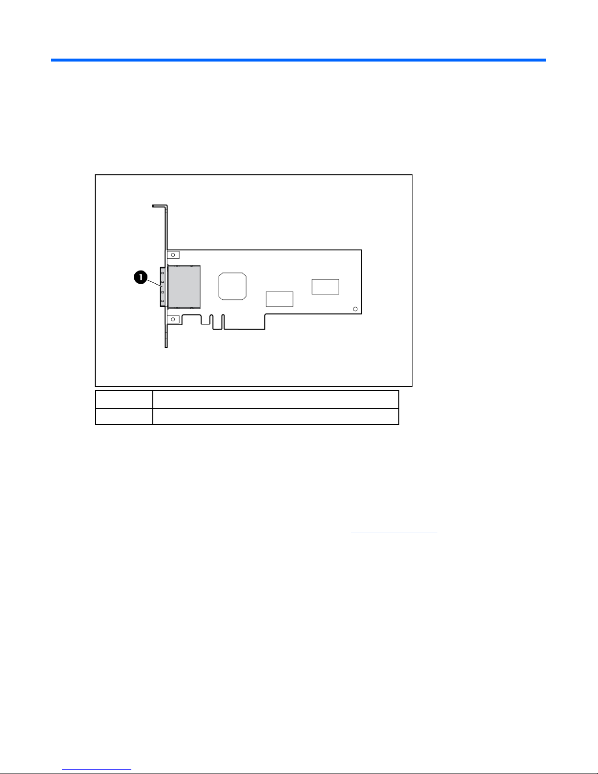
Board features
Item Description
1 Two external mini SAS 4x connectors
Summary of specifications
The HP SC08Ge Host Bus Adapter is a low-profile, 64-bit PCIe adapter that supports transfer rates of up
to 3 Gb/s for SAS and 1.5 Gb/s for SATA.
For more information about the features, specifications, and compatibility of the adapter, see the
QuickSpecs on the product-specific page of the HP website (http://www.hp.com
).
Features 4
Page 5

Installation procedure
Installation overview
WARNING: To reduce the risk of personal injury or damage to the equipment, consult the
safety information and user documentation provided with the server before attempting the
installation.
Many servers are capable of providing energy levels that are considered hazardous and are
intended to be serviced only by qualified personnel who have been trained to deal with these
hazards. Do not remove enclosures or attempt to bypass any interlocks that may be provided
The installation procedure involves the following steps:
1. Preparing the server (on page 5)
2. Installing the adapter hardware (on page 5)
3. Connecting the adapter
4. Completing the installation procedure (on page 6)
for the purpose of removing these hazardous conditions.
WARNING: To reduce the risk of personal injury or damage to the equipment, adequately
stabilize the rack before extending a component outside the rack. Extend only one component
at a time. A rack may become unstable if more than one component is extended.
Preparing the server
1. Update the server ROM. The update file is available on the HP website
(http://h18023.www1.hp.com/support/files/server/us/romflash.html
2. Back up all data.
3. Perform a normal system shutdown.
4. Power down the server.
5. Power down all peripheral devices that are connected to the server.
6. Unplug the AC power cord from the power outlet.
7. Unplug the power cord from the server.
8. Disconnect all peripheral devices from the server.
Installing the adapter hardware
CAUTION: Electrostatic discharge can damage electronic components. Be sure you are
properly grounded before beginning this procedure.
).
Installation procedure 5
Page 6
For more information, see "Electrostatic Discharge (on page 13)."
1. Depending on the server model, remove or open the server access panel.
WARNING: To reduce the risk of personal injury from hot surfaces, allow the drives and the
internal system components to cool before touching them.
2. Locate the PCIe bus expansion slots, and select the slot that you want to use. (For more information,
see the server documentation.)
3. Depending on the server model, remove the retaining screw or open the expansion slot latch that
secures the PCIe slot.
4. Remove the slot cover and save it. You will need to put it back if you decide to remove the adapter
and leave the slot empty.
5. Insert the adapter into the slot, and press it firmly into place. The contacts on the adapter edge must
be fully seated in the system board connector.
6. Depending on the server model, secure the adapter by replacing the retaining screw or by closing
the slot latch.
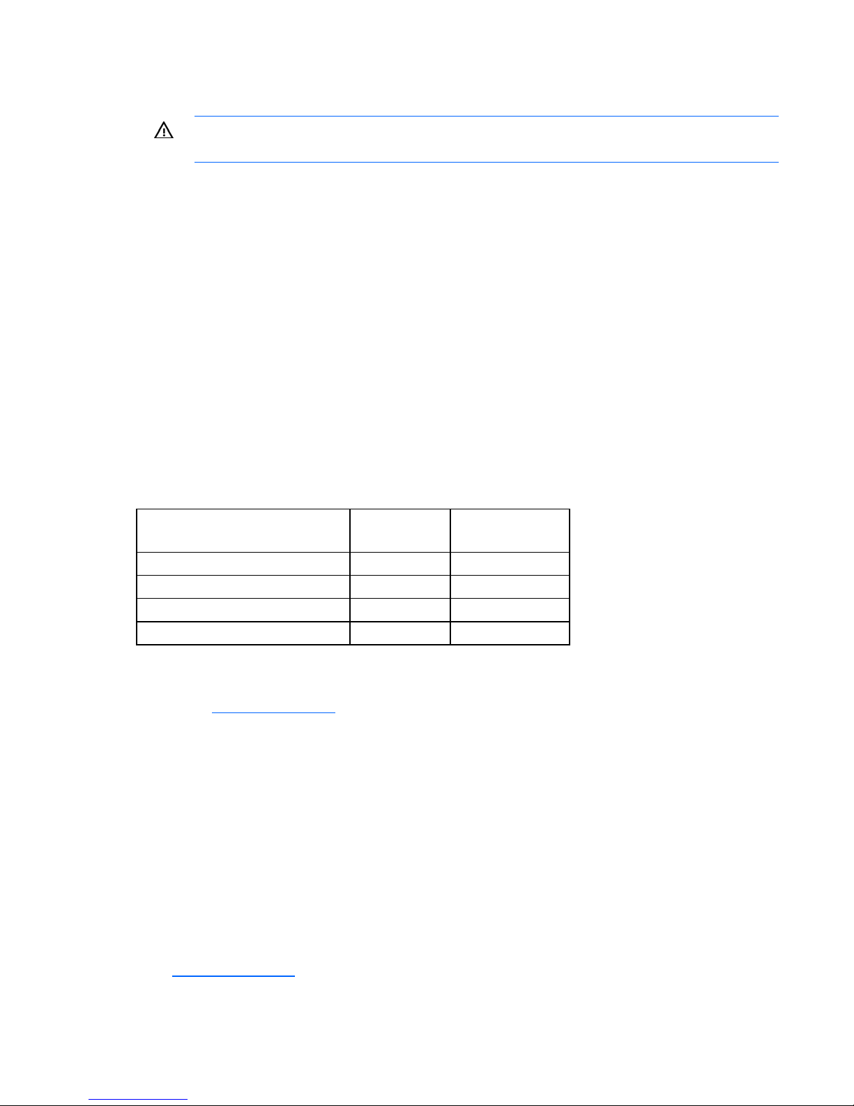
Connecting the adapter
Cables for connecting the adapter to other devices are provided with most HP server products. The
following table lists cables that you can use with this adapter. All HP cables are keyed to ensure correct
installation.
Type of cable Length Cable kit
part number
External Mini SAS 1.0 m (3.3 ft) 407337-002
External Mini SAS 2.0 m (6.6 ft) 407339-B21
External Mini SAS 4.0 m (13 ft) 432238-B21
External Mini SAS 6.0 m (20 ft) 432239-B21
You can order extra cables from an authorized HP reseller or authorized HP service provider. If the cable
that you need is not listed in the preceding table, or if you need additional ordering information, see the
HP website (http://www.hp.com
).
Completing the installation procedure
1. Verify that all cables are routed correctly and are not restricting other components or being pinched
by them. For the correct cable routing, see the server documentation.
2. Connect peripheral devices to the server.
3. Plug the AC power cord into the server.
4. Plug the other end of the power cord into a grounded AC outlet.
5. Power on any peripheral devices attached to the server.
6. Power up the server.
7. Install the adapter drivers. The drivers are available on the CD in the adapter kit or the HP website
(http://www.hp.com
). Instructions are provided with the driver files.
Installation procedure 6
Page 7

SAS BIOS configuration utility
SAS BIOS features
The SAS BIOS is the bootable ROM code that manages SAS hardware resources. It is specific to a family
of SAS controllers and processors. The SAS BIOS integrates with a standard system BIOS, extending the
standard disk-service routine provided through INT13h.
During initialization, the SAS BIOS determines if the system BIOS has already installed other hard disks,
such as an IDE drive. If other drives are already installed, the SAS BIOS maps any SAS or SATA drives it
finds behind these drives. Otherwise, the SAS BIOS installs drives starting with the system boot drive, and
then the system boots from a drive controlled by the SAS BIOS.
The SAS BIOS supports the BIOS boot specification (BBS). If the system supports the BBS, use the system
BIOS setup menu to select the boot order and drive order. In the system BIOS setup, the Boot Connection
Devices menu lists the available boot options. Select the device and boot order. Exit to continue the boot
process.
Starting the SAS BIOS configuration utility
SAS BIOS 6.xx, with the SAS BIOS configuration utility, enables you to change the default configuration
of SAS host adapters. The default configuration might need to be changed if the adapter conflicts with
other devices or if system performance needs optimization.
The version number of the SAS BIOS appears during boot. If the configuration utility is available, the
following message also appears:
Press F8 to start LSI Logic Configuration Utility...
The exact key sequence required to start the utility might vary for different versions of the utility.
This message remains on the screen for 5 seconds, giving you time to start the utility. If you start the utility,
the screen displays the following message:
Please wait, invoking LSI Logic Configuration Utility...
After a pause, the SAS BIOS configuration utility opens.
The following messages might appear during the boot process:
• Adapter removed from boot order!
This message appears when an adapter was removed from the system or was relocated behind a
PCI bridge.
• Adapter configuration may have changed, reconfiguration is suggested!
This message appears when the information in the NVRAM is invalid.
• Updating adapter list!
This message appears when fewer than four adapters are in the boot-order list, and more adapters
exist than are shown.
SAS BIOS configuration utility 7
Page 8

The SAS BIOS configuration utility can detect devices that the SAS BIOS cannot control (for example, tape
drives and scanners). However, the configuration utility can still be used to modify certain parameters for
these devices.
Configuration utility screens
All SAS BIOS configuration utility screens contain the following areas, starting at the top of the screen:
• Header—Identifies the utility and version number.
• Menu—Displays the title of the current screen and also identifies the adapter on screens other than
the Adapter List screen.
• Main area—The main area for presenting data. This area has a cursor for item selection, and
horizontal and vertical scroll bars if necessary.
• Footer—Provides general help information text.
Adapter List screen
The Adapter List screen provides information about each adapter installed in the system. This screen is the
first screen to appear when the SAS BIOS configuration utility opens.
If the host bus adapter is configured as the active boot controller in RBSU, you can perform the following
actions:
• Change the position of an adapter in the boot-order sequence by moving the cursor to the Boot
Order field of the adapter and then pressing the - or + key.
• Add an adapter to the Boot Order list by moving the cursor to the Boot Order field of the adapter
and then pressing the Ins key.
• Remove an adapter from the Boot Order list by moving the cursor to the Boot Order field of the
adapter and then pressing the Del key.
You are prompted to save the changes before exiting the screen.
The Adapter List screen enables you to access the rest of the utility through the Adapter Properties screen
(on page 9). To access the Adapter Properties screen, select a listed adapter, and then press the Enter
key.
SAS BIOS configuration utility 8
Page 9

Adapter Properties screen
The Adapter Properties screen provides information about the adapter, and gives you access to other
screens that enable you to view information about devices connected to the adapter.
To view information about devices connected to the adapter, move the cursor to the SAS Topology field,
and then press the Enter key.
SAS Topology screen
The SAS Topology screen provides basic information about each device connected to the adapter and
provides the ability to identify the physical device in the system that corresponds to a device in the list.
Scroll horizontally to view all the information listed for a device. To access this screen, select the SAS
Topology link on the Adapter Properties screen.
• To view detailed information about a device, move the cursor to the appropriate Device Identifier
field, and then press Alt+D. The Device Properties screen is displayed.
• To identify the physical device corresponding to a listed device, move the cursor to the appropriate
Device Identifier field, and then press Enter. The locator LED on the device is lit.
SAS BIOS configuration utility 9
Page 10

• To clear Device Mappings for missing devices, press C at any time while on this screen.
Device Properties screen
The Device Properties screen displays information about a specific device. To access this screen, press
Alt+D when the cursor is in the Device Identifier field of a device on the SAS Topology screen.
• To move to the next device, press Alt+N.
• To move back to the previous device, press Alt+P.
This screen also provides access to the Format and Verify screens. To reach either of these screens, move
the cursor to the appropriate field, and then press Enter.
Device Format screen
Use the Format screen to format a particular device. To access this screen, press Enter in the appropriate
field on the Device Properties screen.
SAS BIOS configuration utility 10
Page 11

CAUTION: After a format is started it cannot be paused or cancelled.
To begin the format, press F.
The formatting procedure sets the sector size to 512 bytes, even if the drive was previously formatted to
another sector size. This is the only sector size that the SAS BIOS configuration utility supports on RAID
volumes.
Device Verify screen
Use the Device Verify screen to verify a particular device. To access this screen, press Enter in the
appropriate field on the Device Properties screen.
Press Enter to begin the verify process. Press Esc to cancel the verify process at any time.
If the logical block addresses (LBAs) can be reassigned or must be reassigned, the following prompt
appears after pressing Enter:
Reassign the block?
(Yes, No, All, nonE, Cancel)
The reassignment options are as follows:
• Yes—Reassign only this block. If another block must be reassigned in the future, display the prompt
again.
• No—Do not reassign this block. If another block must be reassigned in the future, display the prompt
again.
• All—Reassign the current block, and automatically reassign other blocks that must be reassigned,
without displaying the prompt again.
• nonE—Do not reassign the current block, and do not automatically reassign any other blocks that
must be reassigned. Do not display the prompt again.
• Cancel—Do not reassign any blocks and stop the verify process.
SAS BIOS configuration utility 11
Page 12

Exit Menu screen
The SAS BIOS configuration utility must be exited properly because some changes take effect only during
the exit process.
To access the Exit Menu screen, press Esc from any screen in the utility.
If an option is not relevant or not available, it is deactivated.
Performing configuration tasks
Locating a disk drive
There are two ways to physically locate a disk drive:
• On the Create New Array screen, the drive locator LED is on when a drive is selected to be part of a
RAID volume. When the RAID volume is created, or the drive is deselected from the volume, the
locator LED is off.
• On the SAS Topology screen, move the cursor to the drive, and then press Enter. The locator LED on
Selecting a boot disk
the drive remains lit until another key is pressed.
To select a boot disk:
1. On the Adapter List screen, select an adapter.
2. On the Adapter Properties screen, select SAS Topology. The SAS Topology screen is displayed. If
selection of a boot device is supported, the Alt+B option is listed at the bottom of the screen. If a
device is currently configured as the boot device, the Device Info column displays the word Boot.
o To remove the boot disk designator, move the cursor to the current boot disk and press Alt+B.
The adapter no longer has a designated boot device.
o To select a boot disk, move the cursor to the disk, and press Alt+B. The selected disk moves to
scan ID 0 on the next boot and remains at this position. There can be only one boot disk.
SAS BIOS configuration utility 12
Page 13

Electrostatic discharge
Preventing electrostatic discharge
To prevent damaging the system, be aware of the precautions you need to follow when setting up the
system or handling parts. A discharge of static electricity from a finger or other conductor may damage
system boards or other static-sensitive devices. This type of damage may reduce the life expectancy of the
device.
To prevent electrostatic damage:
• Avoid hand contact by transporting and storing products in static-safe containers.
• Keep electrostatic-sensitive parts in their containers until they arrive at static-free workstations.
• Place parts on a grounded surface before removing them from their containers.
• Avoid touching pins, leads, or circuitry.
• Always be properly grounded when touching a static-sensitive component or assembly.
Grounding methods to prevent electrostatic
discharge
Several methods are used for grounding. Use one or more of the following methods when handling or
installing electrostatic-sensitive parts:
• Use a wrist strap connected by a ground cord to a grounded workstation or computer chassis. Wrist
straps are flexible straps with a minimum of 1 megohm ±10 percent resistance in the ground cords.
To provide proper ground, wear the strap snug against the skin.
• Use heel straps, toe straps, or boot straps at standing workstations. Wear the straps on both feet
when standing on conductive floors or dissipating floor mats.
• Use conductive field service tools.
• Use a portable field service kit with a folding static-dissipating work mat.
If you do not have any of the suggested equipment for proper grounding, have an authorized reseller
install the part.
For more information on static electricity or assistance with product installation, contact an authorized
reseller.
Electrostatic discharge 13
Page 14

Regulatory compliance notices
Federal Communications Commission notice
Part 15 of the Federal Communications Commission (FCC) Rules and Regulations has established Radio
Frequency (RF) emission limits to provide an interference-free radio frequency spectrum. Many electronic
devices, including computers, generate RF energy incidental to their intended function and are, therefore,
covered by these rules. These rules place computers and related peripheral devices into two classes, A
and B, depending upon their intended installation. Class A devices are those that may reasonably be
expected to be installed in a business or commercial environment. Class B devices are those that may
reasonably be expected to be installed in a residential environment (for example, personal computers).
The FCC requires devices in both classes to bear a label indicating the interference potential of the device
as well as additional operating instructions for the user.
FCC rating label
The FCC rating label on the device shows the classification (A or B) of the equipment. Class B devices
have an FCC logo or ID on the label. Class A devices do not have an FCC logo or ID on the label. After
you determine the class of the device, refer to the corresponding statement.
Class A equipment
This equipment has been tested and found to comply with the limits for a Class A digital device, pursuant
to Part 15 of the FCC Rules. These limits are designed to provide reasonable protection against harmful
interference when the equipment is operated in a commercial environment. This equipment generates,
uses, and can radiate radio frequency energy and, if not installed and used in accordance with the
instructions, may cause harmful interference to radio communications. Operation of this equipment in a
residential area is likely to cause harmful interference, in which case the user will be required to correct
the interference at personal expense.
Class B equipment
This equipment has been tested and found to comply with the limits for a Class B digital device, pursuant
to Part 15 of the FCC Rules. These limits are designed to provide reasonable protection against harmful
interference in a residential installation. This equipment generates, uses, and can radiate radio frequency
energy and, if not installed and used in accordance with the instructions, may cause harmful interference
to radio communications. However, there is no guarantee that interference will not occur in a particular
installation. If this equipment does cause harmful interference to radio or television reception, which can
be determined by turning the equipment off and on, the user is encouraged to try to correct the
interference by one or more of the following measures:
• Reorient or relocate the receiving antenna.
• Increase the separation between the equipment and receiver.
Regulatory compliance notices 14
Page 15

• Connect the equipment into an outlet on a circuit that is different from that to which the receiver is
connected.
• Consult the dealer or an experienced radio or television technician for help.
Declaration of conformity for products marked with
the FCC logo, United States only
This device complies with Part 15 of the FCC Rules. Operation is subject to the following two conditions:
(1) this device may not cause harmful interference, and (2) this device must accept any interference
received, including interference that may cause undesired operation.
For questions regarding this product, contact us by mail or telephone:
• Hewlett-Packard Company
P. O. Box 692000, Mail Stop 530113
Houston, Texas 77269-2000
• 1-800-HP-INVENT (1-800-474-6836). (For continuous quality improvement, calls may be recorded
or monitored.)
For questions regarding this FCC declaration, contact us by mail or telephone:
• Hewlett-Packard Company
P. O. Box 692000, Mail Stop 510101
Houston, Texas 77269-2000
• 1281-514-3333
To identify this product, refer to the part, series, or model number found on the product.
Modifications
The FCC requires the user to be notified that any changes or modifications made to this device that are
not expressly approved by Hewlett-Packard Company may void the user’s authority to operate the
equipment.
Cables
Connections to this device must be made with shielded cables with metallic RFI/EMI connector hoods in
order to maintain compliance with FCC Rules and Regulations.
Canadian notice (Avis Canadien)
Class A equipment
This Class A digital apparatus meets all requirements of the Canadian Interference-Causing Equipment
Regulations.
Cet appareil numérique de la classe A respecte toutes les exigences du Règlement sur le matériel
brouilleur du Canada.
Class B equipment
Regulatory compliance notices 15
Page 16

This Class B digital apparatus meets all requirements of the Canadian Interference-Causing Equipment
Regulations.
Cet appareil numérique de la classe B respecte toutes les exigences du Règlement sur le matériel
brouilleur du Canada.
European Union regulatory notice
This product complies with the following EU Directives:
• Low Voltage Directive 2006/95/EC
• EMC Directive 2004/108/EC
Compliance with these directives implies conformity to applicable harmonized European standards
(European Norms) which are listed on the EU Declaration of Conformity issued by Hewlett-Packard for this
product or product family.
This compliance is indicated by the following conformity marking placed on the product:
This marking is valid for non-Telecom products and EU harmonized Telecom products (e.g. Bluetooth).
This marking is valid for EU non-harmonized Telecom products.
*Notified body number (used only if applicable—refer to the product label)
Hewlett-Packard GmbH, HQ-TRE, Herrenberger Strasse 140, 71034 Boeblingen, Germany
BSMI notice
Regulatory compliance notices 16
Page 17

Japanese notice
Korean notice
Class A equipment
Class B equipment
Regulatory compliance notices 17
Page 18

Acronyms and abbreviations
LBA
logical block addressing
NVRAM
non-volatile memory
RBSU
ROM-Based Setup Utility
SAS
serial attached SCSI
SATA
serial ATA
Acronyms and abbreviations 18
 Loading...