

Page 1

HP 6Gb SAS BL Switch User Guide
The HP 6Gb SAS BL Switch is a single-wide interconnect module for HP BladeSystem c-Class enclosures. The HP 6Gb SAS BL
Switch is one of the key components in HP External SAS Storage for HP BladeSystem Solutions, with firmware and hardware
capabilities that enable the connection of external storage enclosures and tape devices to HP BladeSystem c-Class enclosures.
HP Part Number: 634036-003
Published: September 2012
Edition: 3
Page 2

© Copyright 2011, 2012 Hewlett-Packard Development Company, L.P.
The information contained herein is subject to change without notice. The only warranties for HP products and services are set forth in the express
warranty statements accompanying such products and services. Nothing herein should be construed as constituting an additional warranty. HP shall
not be liable for technical or editorial errors or omissions contained herein.
Acknowledgments
Microsoft® is a U.S. registered trademark of Microsoft Corporation.
Warranty
WARRANTY STATEMENT: To obtain a copy of the warranty for this product, see the warranty information website:
http://www.hp.com/go/storagewarranty
Revision History
April 2011Revision #1
Initial release, showing support for shared SAS storage (P2000 G3 SAS MSA arrays)
September 2011Revision #2
Added information about zoned SAS storage (HP MDS600 and D2000 drive enclosures)
September 2012Revision #3
Added information about the HP P721m Smart Array Controller and the HP D6000 Disk Enclosure
Page 3

Contents
1 Introduction...............................................................................................5
Features..................................................................................................................................5
Supported devices....................................................................................................................6
Shared SAS storage enclosures (P2000 G3 SAS MSA arrays)....................................................6
Zoned SAS storage enclosures (MDS600, D6000, and D2600/D2700 drive enclosures)..............6
Tape devices.......................................................................................................................7
2 Component identification.............................................................................8
3 Installation procedures................................................................................9
Getting started.........................................................................................................................9
Planning the configuration.........................................................................................................9
Selecting the interconnect bay..................................................................................................10
Installing the switch.................................................................................................................11
Accessing the switch...............................................................................................................13
Updating switch firmware........................................................................................................13
Connecting cables to the switch................................................................................................15
Cabling best practices........................................................................................................15
Cabling example...............................................................................................................16
MDS600 or D6000 dual domain, standard cabling..........................................................16
Configuring the switch.............................................................................................................17
4 Supported software tools...........................................................................18
HP Onboard Administrator overview.........................................................................................18
HP 6G Virtual SAS Manager overview......................................................................................20
5 Firmware.................................................................................................21
6 Troubleshooting........................................................................................22
7 Technical specifications.............................................................................23
General specifications.............................................................................................................23
Power and environmental specifications.....................................................................................23
8 Electrostatic discharge...............................................................................24
Preventing electrostatic discharge..............................................................................................24
Grounding methods to prevent electrostatic discharge .................................................................24
9 Support and other resources......................................................................25
Contacting HP........................................................................................................................25
Related information.................................................................................................................25
HP websites......................................................................................................................25
Typographic conventions.........................................................................................................25
Rack stability..........................................................................................................................26
Customer self repair................................................................................................................26
HP Insight Remote Support software..........................................................................................27
10 Product documentation survey...................................................................28
A Regulatory compliance notices...................................................................29
Regulatory compliance identification numbers............................................................................29
Federal Communications Commission notice..............................................................................29
FCC rating label................................................................................................................29
Class A equipment........................................................................................................29
Class B equipment........................................................................................................29
Declaration of Conformity for products marked with the FCC logo, United States only.................30
Modification.....................................................................................................................30
Contents 3
Page 4

Cables.............................................................................................................................30
Canadian notice (Avis Canadien).............................................................................................30
Class A equipment.............................................................................................................30
Class B equipment.............................................................................................................30
European Union notice............................................................................................................30
Japanese notices....................................................................................................................31
Korean notices.......................................................................................................................31
Class A equipment.............................................................................................................31
Class B equipment.............................................................................................................31
BSMI Class A notice...............................................................................................................32
Chinese notice.......................................................................................................................32
Vietnam compliance marking...................................................................................................32
Turkish recycling notice............................................................................................................32
Recycling notices....................................................................................................................32
English recycling notice......................................................................................................32
Bulgarian recycling notice...................................................................................................33
Czech recycling notice........................................................................................................33
Danish recycling notice.......................................................................................................33
Dutch recycling notice.........................................................................................................33
Estonian recycling notice.....................................................................................................34
Finnish recycling notice.......................................................................................................34
French recycling notice.......................................................................................................34
German recycling notice.....................................................................................................34
Greek recycling notice........................................................................................................35
Hungarian recycling notice.................................................................................................35
Italian recycling notice........................................................................................................35
Latvian recycling notice.......................................................................................................35
Lithuanian recycling notice..................................................................................................36
Polish recycling notice.........................................................................................................36
Portuguese recycling notice.................................................................................................36
Romanian recycling notice..................................................................................................36
Slovak recycling notice.......................................................................................................37
Spanish recycling notice.....................................................................................................37
Swedish recycling notice.....................................................................................................37
Index.........................................................................................................38
4 Contents
Page 5

1 Introduction
The HP 6Gb SAS BL Switch is a single-wide interconnect module for HP BladeSystem c-Class
enclosures that enables a server blade with an HP Smart Array 6Gb SAS Controller to communicate
with external SAS storage enclosures and tape devices. Its 6Gb SAS technology delivers high
performance, with high data bandwidth up to 600 MB/s per physical link, and is fully compatible
with 3G SAS, 3G SATA, and 1.5G SATA technology. Both dual-port SAS and single-port SATA
disk drive interconnections are supported, offering deployment flexibility.
The HP 6Gb SAS BL Switch is a key component in HP External SAS Storage for HP BladeSystem
Solutions.
• For information about devices included in the BladeSystem portfolio, including c-Class
enclosures, ProLiant server blades, Smart Array SAS controllers, and this 6Gb SAS BL Switch,
see the HP BladeSystem website (http://www.hp.com/go/bladesystem).
• For information about BladeSystem solutions using this switch, see the HP BladeSystem
Deployment Guide for Solutions with 6Gb SAS BL Switches and External SAS Storage
Enclosures, available on the HP Support Center website (http://www.hp.com/go/hpsc).
Features
Simplified management:
• BladeSystem c-Class enclosures and their blade devices centralize control and reduce storage
management cost.
• The HP 6G Virtual SAS Manager application, used for zoning, is embedded in the switch
firmware.
Enterprise-class performance:
• The HP 6Gb SAS BL Switch is fully supported in the HP BladeSystem c-Class enclosure
infrastructure and is compatible with any combination of HP BladeSystem c-Class server blades.
• An existing switch can be installed or replaced without having to power down the BladeSystem
enclosure.
• Configuration and management is performed through the embedded Virtual SAS Manager
(VSM) utility. The VSM is available in both a Graphical User Interface (GUI) and a Command
Line Interface (CLI).
High availability when using a pair of switches in the same interconnect row of the BladeSystem
c-Class enclosure:
• The inclusion of a redundant SAS BL Switch and SAS Smart Array Controller, along with dual
I/O modules in the external storage enclosures and dual-ported disk drives, ensures that the
system can tolerate a component or path failure and maintain access to the storage.
• Redundant power supplies and redundant cooling fans within the BladeSystem c-Class enclosure
provide protection against enclosure malfunction.
• Redundant firmware images and configuration settings provide protection against switch or
port malfunctions.
Features 5
Page 6

Supported devices
The HP 6Gb SAS BL Switch supports the following types of devices:
• “Shared SAS storage enclosures (P2000 G3 SAS MSA arrays)” (page 6)
• “Zoned SAS storage enclosures (MDS600, D6000, and D2600/D2700 drive enclosures)”
(page 6)
• “Tape devices” (page 7)
For information about cabling and configuring the switch and any attached devices, see “Connecting
cables to the switch” (page 15).
Shared SAS storage enclosures (P2000 G3 SAS MSA arrays)
When shared SAS storage enclosures are attached to the switch:
• The storage enclosure includes an embedded RAID array controller, which is used to configure
the logical storage units (LUNs). An example of a shared SAS storage enclosure is the HP
P2000 G3 SAS MSA Array System.
• The BladeSystem server blade must have a RAID array controller installed, which communicates
with the RAID array controller in the storage enclosure, but it is not used for its RAID
configuration capabilities.
• The SAS BL Switch and the connected SAS storage are configured using switch-port zone
groups. The entire storage enclosure connected to that switch port is visible to all c-Class
enclosure blade ports (server bays) granted access to the zone group that includes that switch
port.
NOTE: Unused switch ports can be included in a zone group, to help plan for future growth.
• Server bays that need access to an external storage enclosure must be assigned the appropriate
zone group.
◦ A server bay can be assigned multiple zone groups.
◦ A switch-port zone group can be assigned to more than one server bay.
◦ Unpopulated server bays can be assigned a zone group.
• Disk drives in the storage enclosure are configured into logical units (LUNs) using a
storage-enclosure based utility such as the HP Storage Management Utility (SMU). Access or
restrictions to the LUNs is controlled through mappings or other presentation methods, which
grant specific server bays access to specific LUNs.
Zoned SAS storage enclosures (MDS600, D6000, and D2600/D2700 drive enclosures)
When zoned SAS storage enclosures are attached to the switch:
• The storage enclosure includes I/O modules (does not include a RAID array controller).
Examples of zoned SAS storage enclosures are the HP MDS600, HP D6000, and HP D2000
(D2600/D2700).
• The BladeSystem server blade must have a RAID array controller installed, and is used for its
6 Introduction
NOTE: The HP MDS6000 is a 3G device; when connected to the 6G SAS BL Switch, all
data traffic will be reduced to 3G.
RAID configuration capabilities.
Page 7

• The SAS BL Switch and the connected SAS storage are configured using drive bay zone
groups. The group of drive bays is presented to the c-Class enclosure blade port (server bay)
as if it was directly connected to that server bay.
NOTE: Unpopulated drive bays in the storage enclosure can be included in a zone group,
to help plan for future growth.
• The server bay that needs access to drive bays must be assigned to the appropriate zone
group.
◦ A server bay can be assigned multiple zone groups.
◦ A drive-bay zone group can be assigned to only one server bay.
◦ Unpopulated server bays can be assigned zone groups.
• Disk drives in the storage enclosure are configured into logical units (LUNs) using host-based
configuration utilities such as HP Array Configuration Utility (ACU).
Tape devices
When tape devices are attached to the switch:
• The tape device is configured using switch port zone groups. The entire tape device connected
to that switch port is presented to all c-Class enclosure blade ports (server bays) granted access
to the zone group.
NOTE: Unused switch ports can be included in a zone group, to help plan for future growth.
• Server bays that need access to tape devices must be assigned the appropriate zone group.
◦ A server bay can be assigned multiple zone groups.
◦ A switch-port zone group can be assigned to more than one server bay.
◦ Unpopulated server bays can be assigned to a zone group.
Supported devices 7
Page 8
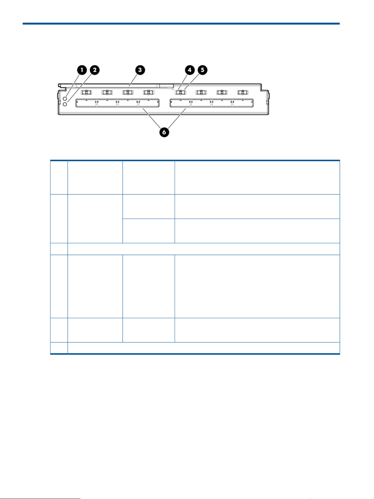
2 Component identification
BlueUnit ID LED1
GreenHealth LED2
Amber
Locking latch handle3
GreenLink LED4
AmberFault LED5
SAS ports (to external devices)6
• Off—Normal
• Solid —Being identified
• Blinking—Firmware is being updated
• Off—Not powered up
• Solid green—Healthy
• Off—Not powered up
• Blinking—Error, there is a problem with the switch
• Off—No link between the server and storage
• Solid —Link between server and storage is established
• Steady blink (1Hz)—Switch hardware or software is starting up.
During this time, access to the switch and its VSM software is
restricted, and server blades with SAS controller cards mapped
to the switch interconnect bay will be restricted from starting up.
• Flickering blink—Activity on the established link
• Off—Normal
• On—Link error, there is a problem with the port
8 Component identification
Page 9

3 Installation procedures
HP 6Gb SAS BL Switch installation procedures include the following steps:
• “Getting started” (page 9)
• “Planning the configuration” (page 9)
• “Selecting the interconnect bay” (page 10)
• “Installing the switch” (page 11)
• “Accessing the switch” (page 13)
• “Updating switch firmware” (page 13)
• “Connecting cables to the switch” (page 15)
• “Configuring the switch” (page 17)
Getting started
• Familiarize yourself with information available on the HP BladeSystem website
nl
http://www.hp.com/go/bladesystem.
Navigate through the website to learn more about BladeSystem c-Class enclosures, the SAS
BL Switch, controller cards, servers, and other BladeSystem components. Product pages,
overviews, QuickSpecs, and user documents for all BladeSystem products are accessible from
this website.
For example:
◦ On the right side of the HP BladeSystem website, under Get started, click Go straight to
products to access the HP BladeSystem c-Class portfolio page, with links to the product
web pages for BladeSystem hardware components, software, and services.
◦ In the left pane of the HP BladeSystem website, click Technical Resources to access the
HP BladeSystem Technical Resources page. Tabs across the top of this page provide
access points for planning, installing, maintaining, and troubleshooting information. User
documents for all BladeSystem components are located on the Installing tab.
• Obtain the following documents; they are needed when planning, installing, and configuring
the switch:
◦ HP BladeSystem Deployment Guide for Solutions with 6Gb SAS BL Switches and External
SAS Storage Enclosures
◦ HP 6G Virtual SAS Manager User Guide
◦ HP 6Gb SAS BL Switch User Guide
◦ HP 6Gb SAS BL Switch QuickSpecs
In addition to being available on the BladeSystem Technical Resources page, these documents
are also available on 6Gb SAS BL Switch page of the HP Support Center website
nl
(http://www.hp.com/go/hpsc).
Planning the configuration
For both single- and dual-domain deployments, a variety of cabling and configuration strategies
are available. Consider the server blades, switches, external storage enclosures, and external
backup devices in your deployment. Develop plans for cabling the external devices and choose
the appropriate zoning method (switch port or drive bay) to control access to the storage.
Getting started 9
Page 10

For assistance, HP strongly recommends using the HP BladeSystem Deployment Guide for Solutions
with 6Gb SAS BL Switches and External SAS Storage Enclosures. The deployment guide provides
guidelines, instructions, and configuration examples for solutions centered around an HP
BladeSystem c-Class enclosure with server blades, SAS BL switches, SAS controller cards, and
external SAS storage enclosures.
Selecting the interconnect bay
The HP 6Gb SAS BL Switch is supported for use in the following c-Class enclosure interconnect
bays:
c7000
1
When using P721m controllers, the 6Gb SAS BL Switch cannot be installed in c7000 interconnect bays 3 and 4. (The
P721m controller cannot be installed in server expansion slot 1, which maps to interconnect bays 3 and 4.)
Each interconnect bay row in an HP BladeSystem c3000 and c7000 enclosure maps to servers
via the server expansion slot in which the HP Smart Array controller card is installed.
Before installing the 6Gb SAS BL Switch in the c-Class enclosure, confirm that the controller and
the switch are installed in server expansion slots and enclosure interconnect bays that map to one
another.
Supported interconnect bayBladeSystem c-Class enclosure model
3 and 4c3000
3, 4, 5, 6, 7, and 8
1
NOTE: Different controller models are required for the different types of external storage or
backup devices being connected to the switch, and these different controller models may be limited
for installation in specific expansion slots which, in turn, may limit which interconnect bays that
the switch can be installed in. For example, when using the P721m controller, because the P721m
controller can only be installed in server expansion slot 2, switches in these environments can only
be installed in c3000 interconnect bays 3 and 4 or c7000 interconnect bays 5, 6, 7, and 8.
For information about supported SAS controllers, see the HP 6Gb SAS BL Switch QuickSpecs.
For information about mappings, see user documents for your BladeSystem c-Class enclosure model.
The following tables list the mappings between server expansion slots and BladeSystem enclosure
interconnect bays. For information about which expansion slots are supported for use with your
controller model, see the user documents for the controller.
Mappings for the c3000 BladeSystem enclosure:
nl
c-Class
nl
enclosure
nl
model
Server typeBladeSystem
Expansion
nl
slot
2Half height
2Full height
BladeSystem
nl
c-Class
nl
interconnect bay
c3000
10 Installation procedures
nl
Double wide
3
2Full height
3/4
3
4
7
Page 11

Mappings for the c7000 BladeSystem enclosure:
nl
c-Class
nl
enclosure
nl
model
Server typeBladeSystem
Expansion
nl
slot
BladeSystem
nl
c-Class
nl
interconnect bay
3/41Half height
5/6/7/8 *2
3/41Full height
5/6/7/8 *2
5/6/7/83
c7000
nl
Double wide
3/41Full height
5/6/7/8 *2
5/6/7/83
5/6/7/84
3/45
5/6/7/87
* When using c7000 enclosures and P721m controllers, the 6Gb SAS BL Switch can be installed only in c7000
interconnect bays 5, 6, 7, and 8, because the P721m controller cannot be installed in server expansion slot 1, which
maps to c7000 interconnect bays 3 and 4.
For more information about mappings, see the HP BladeSystem Deployment Guide for Solutions
with 6Gb SAS BL Switches and External SAS Storage Enclosures and user documents for your
BladeSystem c-Class enclosure model. For information about supported SAS controllers, see the
6Gb SAS BL Switch QuickSpecs.
Installing the switch
NOTE:
• The SAS BL Switch can be hot-installed in an operational BladeSystem c-Class enclosure.
• Make sure that the Smart Array SAS Controllers are installed in server expansion slots that
map to the selected BladeSystem c-Class enclosure interconnect bay.
• The SAS BL Switch does not have a power on/off button. Power is automatically applied or
removed when the switch is installed or removed from the BladeSystem c-Class enclosure.
Alternatively, power can be applied or removed through the Onboard Administrator
application.
• Connect SAS cables to external storage enclosures only after confirming that the desired
firmware version is installed on the switch.
Installing the switch 11
Page 12

1. Remove the air baffle from the selected interconnect bay.
2. Prepare the switch.
3. Install the switch in the open interconnect bay.
When installed in an operational enclosure, the switch automatically powers up and performs
a series of Power On Self Tests before being operational.
NOTE: Do not connect cables to the switch at this time. HP recommends connecting cables
only after confirming that the switch is operational and has the desired, supported version of
firmware installed.
12 Installation procedures
Page 13

4. Note the following during startup:
• All eight switch Link LEDs will blink while the switch and the VSM software are starting
up.
• Startup time is approximately five minutes. If startup is longer than five minutes, confirm
that a supported version of Onboard Administrator is installed on the system.
• After the switch and the VSM software have started up successfully, the switch Health LED
will be solid green.
• If the Health LED is amber or off, remove the switch from the BladeSystem enclosure
Interconnect Bay and reinstall it, pressing firmly on the switch and its locking latch handle
to ensure it is seated properly. If trouble persists, see the "Troubleshooting" section of the
HP BladeSystem enclosure setup and installation guide.
For more information about switch LED patterns, see “Component identification” (page 8).
Accessing the switch
The switch can be accessed, configured, and managed through the Onboard Administrator (OA)
and Virtual SAS Manager (VSM) applications.
To access VSM:
1. Access OA.
NOTE: The minimum OA version offering support for the HP 6Gb SAS BL Switch is 3.10.
2. In the OA Systems and Devices tree, expand the Interconnect Bays, and select the HP 6Gb
SAS BL Switch.
3. After selecting the SAS switch to manage, click Management Console and wait a few moments
for the VSM application to open.
For more information about accessing and using the VSM, see the HP 6G Virtual SAS Manager
User Guide, available on the 6Gb SAS BL Switch page of the HP Support Center website
nl
(http://www.hp.com/go/hpsc.
Updating switch firmware
HP 6Gb SAS BL Switch firmware updates can be performed using the Smart Update Firmware
DVD ISO or the HP Virtual SAS Manager (VSM) utility.
Smart Update Firmware DVD ISO and Firmware Release Sets— These tools deliver tested, compatible
sets of firmware for components included in BladeSystem solutions and are designed to help
manage firmware interdependencies between HP BladeSystem Components. These tools use
executable Smart Component firmware packages. For information about updating firmware using
the Smart Update Firmware DVD or an individual Smart Component package, see the HP
BladeSystem Firmware Maintenance page
nl
(http://h18004.www1.hp.com/products/blades/components/c-class.html).
HP Virtual SAS Manager utility—This utility is embedded in the HP 6Gb SAS BL Switch firmware
and is the software application used to create hardware-based zone groups to control access to
external SAS storage. The VSM uses an image firmware file (.img). For information about the VSM,
see the HP 6G Virtual SAS Manager User Guide, available on the 6Gb SAS BL Switch page of
the HP Support Center website (http://www.hp.com/go/hpsc).
Accessing the switch 13
Page 14

IMPORTANT:
• Before updating switch firmware, HP strongly recommends backing up the existing configuration
for safekeeping. For more information, see the HP 6G Virtual SAS Manager User Guide,
available on the 6Gb SAS BL Switch page of the HP Support Center website (http://
www.hp.com/go/hpsc).
• When two HP 6Gb SAS BL Switches are installed in the same row of an enclosure, make sure
that they are running the same firmware version.
• In single-domain configurations, after the switch is updated, open a maintenance window to
restart the switch and activate the new firmware.
• In dual-domain configurations, if both switches have been updated, restart the active switch
and wait for it to complete its power on sequence and I/O to resume before restarting the
passive switch.
CAUTION: Because it can be difficult to confirm when the transition of I/O between the
switches is complete, HP strongly recommends opening a maintenance window to perform
firmware updates in dual-domain environments.
To update switch firmware:
1. Record the firmware version that is currently-installed on the switch.
The installed firmware version is displayed in the VSM near the center of the HP 6G Virtual
SAS Manager banner. Access the VSM and make note of the firmware version installed on
each SAS BL Switch in the BladeSystem enclosure.
2. Record the latest available firmware version.
Firmware can be obtained from several HP websites, including:
• HP Support Center website (http://www.hp.com/go/hpsc)
This Support site includes download pages for all HP products. The HP 6Gb SAS BL
Switch is listed in the bladesystem section.
• HP BladeSystem Firmware Maintenance page:
nl
http://h18004.www1.hp.com/products/blades/components/c-class.html
This BladeSystem site provides links to BladeSystem Firmware Release Sets and the HP
Smart Update Firmware DVD ISO, which include tested, compatible sets of firmware for
components included in BladeSystem solutions and are designed to help manage firmware
inter-dependencies between HP BladeSystem c-Class components. Select the Compatibility
tab to view version information and download firmware for individual components.
3. If needed, update firmware on the switches to the latest version. For instructions, see the HP
6G Virtual SAS Manager User Guide.
14 Installation procedures
Page 15

Connecting cables to the switch
After confirming that the desired firmware is installed on the switch, connect SAS cables between
the switch and the external SAS storage enclosures or external backup devices. Per your
configuration plan, connect the external devices to switch ports that the desired servers will be
able to access. (See “Getting started” (page 9) and “Planning the configuration” (page 9).)
The 6Gb SAS BL Switch uses SAS cables with mini-SAS universal connectors. For a list of supported
cables, see the SAS BL Switch QuickSpecs.
IMPORTANT: Confirm that firmware installed on the external SAS devices is supported for use
with the firmware installed on the switch. Consult the QuickSpecs for the switch and all attached
external devices and confirm that compatible, supported versions of firmware are installed.
Cabling best practices
• In single-domain configurations (and when using single-port drives), be sure to connect the
cable from the switch to the primary controller or I/O module in the storage enclosure.
• In MDS600 and D6000 high-performance configurations with two cable connections from
the same MDS600/D6000 I/O module to the same 6Gb BL SAS Switch, ensure that both
cables from storage enclosure connect to one of the following pairs of switch ports: 1/2; 3/4;
5/6; or 7/8.
• In high-availability, dual-domain configurations with paired switches, redundant controllers
or I/O modules, and dual-ported SAS disk drives, connect cables from the redundant modules
in the storage enclosure to the same switch port on the paired switches. For example, connect
the storage enclosure to port 2 on each switch. This parallel cabling strategy ensures easier
record-keeping, troubleshooting, and support.
• Ensure that cabling in the back of the rack system does not interfere with system operation or
maintenance. Bind cables loosely with cable ties and route the excess out of the way, along
the side of the rack. When cables are tied together and routed down the side of the rack,
system components and indicators are easily visible and accessible.
• Attach a label near both ends of each cable to identify the device connected to that cable.
Include the device, device name, port, or other useful information.
• Use colored markers or labels to color-code both ends of each cable and help you visually
identify a particular cable without having to read or locate the label.
• Use the shortest possible cable between devices. Shorter cables are easier to manage and
route along the back of the rack. In addition, shorter cables reduce the possibility of signal
attenuation that can occur over longer distances.
IMPORTANT: External storage enclosures are tested and approved for use with specific
cable lengths. Before purchasing and connecting SAS cables to external storage enclosures,
check the QuickSpecs for the device and make sure that cables do not exceed the maximum
supported length.
Connecting cables to the switch 15
Page 16

Cabling example
The following is one example of a configuration using HP 6Gb SAS BL Switches.
For more information about configurations using HP 6Gb SAS BL Switches, see the HP BladeSystem
Deployment Guide for Solutions with 6Gb SAS BL Switches and External SAS Storage Enclosures,
available on the BladeSystem Interconnects page of the HP Support Center website (http://
www.hp.com/go/hpsc).
MDS600 or D6000 dual domain, standard cabling
This example illustrates standard cabling for a high-availability configuration when using dual-port
SAS disk drives. In this configuration, note the following:
• One cable from each I/O module to each switch offers high availability.
Devices and quantities
MDS600 or D6000 storage enclosures: 1
I/O modules: 4
BladeSystem c7000 enclosures: 1
6Gb SAS BL switches: 2
Server blade types: half-height and full-height
Connection details
• Switch in interconnect bay 5:
◦ Port 1: to storage drawer 2, primary
I/O module, port 1
◦ Port 5: to storage drawer 1, primary
I/O module, port 1
• Switch in interconnect bay 6:
◦ Port 1: to storage drawer 2, secondary
I/O module, port 1
◦ Port 5: to storage drawer 1, secondary
I/O module, port 1
16 Installation procedures
Page 17

Configuring the switch
Key configuration tasks include:
1. Entering switch parameters. (Enabling or disabling Multi-initiator mode.)
2. Creating zone groups.
• Switch-port zone groups: For shared SAS storage enclosures (P2000 G3 SAS MSA) and
tape libraries.
• Drive-bay zone groups: For zoned SAS storage enclosures (D6000, MDS600, and
D2600/D2700).
3. Assigning zone groups to servers (c-Class enclosure device bays).
4. Capturing the configuration for safekeeping. HP strongly recommends this step, especially in
single-domain configurations.
The switch is configured using the HP 6G Virtual SAS Manager (VSM) application. For more
information on zoning and configuration tasks, see the HP 6G Virtual SAS Manager User Guide,
available on the HP 6Gb SAS BL Switch page of the HP Support Center website
nl
(http://www.hp.com/go/hpsc).
Configuring the switch 17
Page 18

4 Supported software tools
Primary configuration and management utilities include:
• “HP Onboard Administrator overview” (page 18)
• “HP 6G Virtual SAS Manager overview” (page 20)
HP Onboard Administrator overview
HP BladeSystem Onboard Administrator (OA) is the enclosure management processor, subsystem,
and firmware base used to support the HP BladeSystem c-Class enclosures and the managed
devices contained within the enclosure.
Onboard Administrator provides a single point from which to view the entire HP BladeSystem
c-Class environment and perform basic management tasks on BladeSystem devices, including
server blades and switches installed in the enclosure. Using pre-configured hardware parameters,
OA performs initial configuration steps for the enclosure, allows for run-time management and
configuration of the enclosure components, and informs you of problems within the enclosure
through e-mail, SNMP, or the Insight Display For more Information about using OA, see the HP
BladeSystem Onboard Administrator User Guide.
Onboard Administrator can be used to access the HP Virtual SAS Manager application on switches
installed in the HP BladeSystem c-Class enclosure.
The following image shows the Rack Topology view of the front and rear of a c7000 enclosure,
with the primary navigation tree on the left-side of the display. As shown in this example, one
half-height server blade is installed in device bays 1, and four SAS BL switches are installed in
interconnect bays 5, 6, 7, and 8.
18 Supported software tools
Page 19

As shown in the following image, selecting an item in the navigation tree displays management
and monitoring tasks for the selected device. For example, when a SAS BL Switch installed in
interconnect bay 5 is selected in the navigation tree, additional information about the device is
displayed, with tabs at the top of the display providing additional functions.
After selecting a switch, you can click options to:
• View switch status information
• View other switch information
• Click virtual buttons, including the following:
Power off the switch◦
◦ Reset the switch
◦ Toggle on/off the UID light
• Open the Management Console (HP Virtual SAS Manager)
• Open the Port Mapping window to view detailed port mapping information
HP Onboard Administrator overview 19
Page 20

HP 6G Virtual SAS Manager overview
HP 6G Virtual SAS Manager (VSM) is embedded in the HP 6Gb SAS BL Switch firmware and is
the software application used to create hardware-based zone groups to control access to external
SAS storage enclosures and tape devices. Servers in the c-Class enclosure are then granted access
to these zone groups, allowing them to access the storage.
Available in both a graphical user interface (GUI) and command line interface (CLI), VSM offers
the following key tasks:
• Configure switch parameters
• Create zone groups
• Assign zone groups to servers
• Reset the switch
• Update firmware
For information on the VSM, see its online help and the HP 6G Virtual SAS Manager User Guide,
available on the HP 6Gb SAS BL Switch page of the HP Support Center website
nl
(http://www.hp.com/go/hpsc.
The following image shows an example page of the VSM.
IMPORTANT: Storage is configured, formatted, and partitioned using software utilities such as
the HP Array Configuration Utility (ACU), HP P2000 G3 MSA System Storage Management Utility
(SMU), and Microsoft Disk Manager. Depending on your operating system environment and type
of storage enclosures (shared SAS or zoned SAS), the configuration tools used may differ. For
more information, see the QuickSpecs for the storage enclosure.
20 Supported software tools
Page 21

5 Firmware
As part of a routine system maintenance program, periodically check firmware versions installed
on all devices in your solution, including the SAS BL Switch. Updated firmware may include
additional features and functions, performance enhancements, support for newly released hardware,
or fixes to known issues.
HP SAS BL Switch firmware updates can be performed using the HP Smart Update Firmware DVD
or the HP Virtual SAS Manager (VSM) utility.
• Smart Update Firmware DVD ISO and Firmware Release Sets— These tools deliver tested,
compatible sets of firmware for components included in BladeSystem solutions and are designed
to help manage firmware interdependencies between HP BladeSystem Components. These
tools use executable SmartComponent firmware packages. For information about updating
firmware using the Smart Update Firmware DVD or an individual SmartComponent package,
see the HP BladeSystem Firmware Maintenance page
nl
(http://h18004.www1.hp.com/products/blades/components/c-class.html).
• HP Virtual SAS Manager utility—This utility is embedded in the HP 6Gb SAS BL Switch firmware
and is the software application used to create hardware-based zone groups to control access
to external SAS storage. The VSM uses an image firmware file (.img). For information about
the VSM, see the HP 6G Virtual SAS Manager User Guide.
IMPORTANT:
• When two HP 6Gb SAS BL Switches are installed in the same row of an enclosure, make sure
that they are running the same firmware version.
• Before updating switch firmware, HP strongly recommends backing up the configuration for
safekeeping. For more information, see the HP Virtual SAS Manager User Guide, available
on the 6Gb SAS BL Switch page of the HP Support Center website (http://www.hp.com/go/
hpsc).
• Regardless of firmware updating method, HP strongly recommends that firmware updates be
performed during a scheduled maintenance window (single-domain and dual-domain
deployments).
21
Page 22

6 Troubleshooting
SolutionProblem
Amber LED on Switch
Storage not ready during POST (blade) OR Controller
lockup during POST
VSM application is not accessible
Unable to access the storage
• Check OA and VSM for status alerts to identify the
problem.
• See “Component identification” (page 8) for LED
definitions.
Verify the power up sequence and allow sufficient time for
each component to power up. Verify cabling from the
switch to the storage enclosures. For more information
about cabling, see “Connecting cables to the switch”
(page 15).
Verify the power up sequence and allow sufficient time for
each component to power up.
• Verify that the P711m/712m/P721m SAS controller
and the 6Gb SAS Bl Switch are installed in server
expansion slots and BladeSystem interconnect bays that
map to one another. For information about mappings,
see “Selecting the interconnect bay” (page 10).
• Verify that the SAS controller and the storage enclosure
are supported for use with each other. For support
information, see the HP 6Gb SAS BL Switch QuickSpecs,
or the the “Controller and storage enclosure support
matrix” in the HP BladeSystem Deployment Guide for
Solutions with 6Gb SAS BL Switches and External SAS
Storage Enclosures. Both of these documents are
available on the 6Gb SAS BL Switch page of the HP
Support Center website
nl
(http://www.hp.com/go/hpsc).
22 Troubleshooting
Page 23

7 Technical specifications
General specifications
MPC8343a running at 400MHzCommunications processor
2.35 Kg (5.2 lbs)Weight
Power and environmental specifications
6Gb/s SAS x2To server blades:Data path
6Gb/s SAS x4To SAS disk drives:
3Gb/s x4To SATA disk drives:
2.79 cm (1.1 in)HeightDimensions
19.263 cm (7.584 in)Width
26.792 cm (10.548 in)Length
Operating temperature
Operating humidity (non-condensing)
10° to 35°C (50° to 95°F) at sea level with an altitude
derating of 1.0°C per every 305m (1.8°F per every 1000ft)
above sea level to a maximum of 3050m (10,000ft), no
direct sustained sunlight. Maximum rate of change is
10°C/Hr (18°F/Hr). The upper limit may be limited by the
type and number of options installed.
10% to 90% relative humidity (RH), 28°C (82.4°F)
maximum wet bulb temperature, non-condensing.
40 Watts (Max); 3 Watts (Min)Power requirement
General specifications 23
Page 24

8 Electrostatic discharge
Preventing electrostatic discharge
To prevent damaging the system, be aware of the precautions you need to follow when setting up
the system or handling parts. A discharge of static electricity from a finger or other conductor may
damage system boards or other static-sensitive devices. This type of damage may reduce the life
expectancy of the device.
To prevent electrostatic damage:
• Avoid hand contact by transporting and storing products in static-safe containers.
• Keep electrostatic-sensitive parts in their containers until they arrive at static-free workstations.
• Place parts on a grounded surface before removing them from their containers.
• Avoid touching pins, leads, or circuitry.
• Always be properly grounded when touching a static-sensitive component or assembly.
Grounding methods to prevent electrostatic discharge
Several methods are used for grounding. Use one or more of the following methods when handling
or installing electrostatic-sensitive parts:
• Use a wrist strap connected by a ground cord to a grounded workstation or computer chassis.
Wrist straps are flexible straps with a minimum of 1 megohm ±10 percent resistance in the
ground cords. To provide proper ground, wear the strap snug against the skin.
• Use heel straps, toe straps, or boot straps at standing workstations. Wear the straps on both
feet when standing on conductive floors or dissipating floor mats.
• Use conductive field service tools.
• Use a portable field service kit with a folding static-dissipating work mat.
If you do not have any of the suggested equipment for proper grounding, have an authorized
reseller install the part.
For more information on static electricity or assistance with product installation, contact an authorized
reseller.
24 Electrostatic discharge
Page 25

9 Support and other resources
Contacting HP
For worldwide technical support information, see the HP support website:
http://www.hp.com/support
Before contacting HP, collect the following information:
• Product model names and numbers
• Technical support registration number (if applicable)
• Product serial numbers
• Error messages
• Operating system type and revision level
• Detailed questions
Related information
• HP 6Gb SAS BL Switch installation instructions
• HP 6G Virtual SAS Manager user guide
• HP BladeSystem Deployment Guide for Solutions with 6Gb SAS BL Switches and External SAS
Storage Enclosures
• HP BladeSystem c-Class Solution Overview Setup Poster
• HP BladeSystem c3000/c7000 Enclosure Quick Setup Instructions
• HP BladeSystem c3000/c7000 Enclosure Setup and Installation Guide
• HP BladeSystem Onboard Administrator User Guide
You can find these documents on the Manuals page of the HP Support Center website (http://
www.hp.com/go/hpsc
HP websites
For additional information, see the following HP websites:
• http://www.hp.com
• http://www.hp.com/go/bladesystem
• http://www.hp.com/go/storage
• http://www.hp.com/service_locator
• http://www.hp.com/support
• http://www.hp.com/support/manuals
• http://www.hp.com/support/downloads
Typographic conventions
ElementConvention
Cross-reference links and e-mail addressesBlue text: “Typographic conventions” (page 25)
Website addressesBlue, underlined text: http://www.hp.com
Contacting HP 25
Page 26

ElementConvention
Bold text
Monospace text
Monospace, italic text
• Keys that are pressed
• Text typed into a GUI element, such as a box
• GUI elements that are clicked or selected, such as menu
and list items, buttons, tabs, and check boxes
Text emphasisItalic text
• File and directory names
• System output
• Code
• Commands, their arguments, and argument values
• Code variables
• Command variables
Emphasized monospace textMonospace, bold text
WARNING! Indicates that failure to follow directions could result in bodily harm or death.
CAUTION: Indicates that failure to follow directions could result in damage to equipment or data.
IMPORTANT: Provides clarifying information or specific instructions.
NOTE: Provides additional information.
TIP: Provides helpful hints and shortcuts.
Rack stability
Rack stability protects personnel and equipment.
WARNING! To reduce the risk of personal injury or damage to equipment:
• Extend leveling jacks to the floor.
• Ensure that the full weight of the rack rests on the leveling jacks.
• Install stabilizing feet on the rack.
• In multiple-rack installations, fasten racks together securely.
• Extend only one rack component at a time. Racks can become unstable if more than one
component is extended.
Customer self repair
HP customer self repair (CSR) programs allow you to repair your product. If a CSR part needs
replacing, HP ships the part directly to you so that you can install it at your convenience. Some
parts do not qualify for CSR. Your HP-authorized service provider will determine whether a repair
can be accomplished by CSR.
For more information about CSR, contact your local service provider, or see the CSR website:
http://www.hp.com/go/selfrepair
26 Support and other resources
Page 27

HP Insight Remote Support software
HP strongly recommends that you install HP Insight Remote Support software to complete the
installation or upgrade of your product and to enable enhanced delivery of your HP Warranty,
HP Care Pack Service or HP contractual support agreement. HP Insight Remote Support supplements
your monitoring, 24x7 to ensure maximum system availability by providing intelligent event
diagnosis, and automatic, secure submission of hardware event notifications to HP, which will
initiate a fast and accurate resolution, based on your product’s service level. Notifications may be
sent to your authorized HP Channel Partner for on-site service, if configured and available in your
country. The software is available in two variants:
• HP Insight Remote Support Standard: This software supports server and storage devices and
is optimized for environments with 1-50 servers. Ideal for customers who can benefit from
proactive notification, but do not need proactive service delivery and integration with a
management platform.
• HP Insight Remote Support Advanced: This software provides comprehensive remote monitoring
and proactive service support for nearly all HP servers, storage, network, and SAN
environments, plus selected non-HP servers that have a support obligation with HP. It is
integrated with HP Systems Insight Manager. A dedicated server is recommended to host both
HP Systems Insight Manager and HP Insight Remote Support Advanced.
Details for both versions are available at:
http://www.hp.com/go/insightremotesupport
To download the software for free, go to Software Depot:
http://www.software.hp.com
Select Insight Remote Support from the menu on the right.
HP Insight Remote Support software 27
Page 28

10 Product documentation survey
Are you the person who installs, maintains, or uses this HP storage product? If so, we would like
to know more about your experience using the product documentation. If not, please pass this
notice to the person who is responsible for these activities.
Our goal is to provide you with documentation that makes our storage hardware and software
products easy to install, operate, and maintain. Your feedback is invaluable in letting us know how
we can improve your experience with HP documentation.
Please take 10 minutes to visit the following web site and complete our online survey. This will
provide us with valuable information that we will use to improve your experience in the future.
http://www.hp.com/support/storagedocsurvey
Thank you for your time and your investment in HP storage products.
28 Product documentation survey
Page 29

A Regulatory compliance notices
This section contains regulatory notices.
Regulatory compliance identification numbers
For the purpose of regulatory compliance certifications and identification, this product has been
assigned a unique regulatory model number. The regulatory model number can be found on the
product nameplate label, along with all required approval markings and information. When
requesting compliance information for this product, always refer to this regulatory model number.
The regulatory model number is not the marketing name or model number of the product.
Federal Communications Commission notice
Part 15 of the Federal Communications Commission (FCC) Rules and Regulations has established
Radio Frequency (RF) emission limits to provide an interference-free radio frequency spectrum.
Many electronic devices, including computers, generate RF energy incidental to their intended
function and are, therefore, covered by these rules. These rules place computers and related
peripheral devices into two classes, A and B, depending upon their intended installation. Class A
devices are those that may reasonably be expected to be installed in a business or commercial
environment. Class B devices are those that may reasonably be expected to be installed in a
residential environment (for example, personal computers). The FCC requires devices in both classes
to bear a label indicating the interference potential of the device as well as additional operating
instructions for the user.
FCC rating label
The FCC rating label on the device shows the classification (A or B) of the equipment. Class B
devices have an FCC logo or ID on the label. Class A devices do not have an FCC logo or ID on
the label. After you determine the class of the device, refer to the corresponding statement.
Class A equipment
This equipment has been tested and found to comply with the limits for a Class A digital device,
pursuant to Part 15 of the FCC rules. These limits are designed to provide reasonable protection
against harmful interference when the equipment is operated in a commercial environment. This
equipment generates, uses, and can radiate radio frequency energy and, if not installed and used
in accordance with the instructions, may cause harmful interference to radio communications.
Operation of this equipment in a residential area is likely to cause harmful interference, in which
case the user will be required to correct the interference at personal expense.
Class B equipment
This equipment has been tested and found to comply with the limits for a Class B digital device,
pursuant to Part 15 of the FCC Rules. These limits are designed to provide reasonable protection
against harmful interference in a residential installation. This equipment generates, uses, and can
radiate radio frequency energy and, if not installed and used in accordance with the instructions,
may cause harmful interference to radio communications. However, there is no guarantee that
interference will not occur in a particular installation. If this equipment does cause harmful
interference to radio or television reception, which can be determined by turning the equipment
off and on, the user is encouraged to try to correct the interference by one or more of the following
measures:
• Reorient or relocate the receiving antenna.
• Increase the separation between the equipment and receiver.
• Connect the equipment into an outlet on a circuit that is different from that to which the receiver
is connected.
• Consult the dealer or an experienced radio or television technician for help.
Regulatory compliance identification numbers 29
Page 30

Declaration of Conformity for products marked with the FCC logo, United States only
This device complies with Part 15 of the FCC Rules. Operation is subject to the following two
conditions: (1) this device may not cause harmful interference, and (2) this device must accept any
interference received, including interference that may cause undesired operation.
For questions regarding this FCC declaration, contact us by mail or telephone:
• Hewlett-Packard Company P.O. Box 692000, Mail Stop 510101 Houston, Texas 77269-2000
• Or call 1-281-514-3333
Modification
The FCC requires the user to be notified that any changes or modifications made to this device
that are not expressly approved by Hewlett-Packard Company may void the user's authority to
operate the equipment.
Cables
When provided, connections to this device must be made with shielded cables with metallic RFI/EMI
connector hoods in order to maintain compliance with FCC Rules and Regulations.
Canadian notice (Avis Canadien)
Class A equipment
This Class A digital apparatus meets all requirements of the Canadian Interference-Causing
Equipment Regulations.
Cet appareil numérique de la class A respecte toutes les exigences du Règlement sur le matériel
brouilleur du Canada.
Class B equipment
This Class B digital apparatus meets all requirements of the Canadian Interference-Causing
Equipment Regulations.
Cet appareil numérique de la class B respecte toutes les exigences du Règlement sur le matériel
brouilleur du Canada.
European Union notice
Products bearing the CE marking comply with the following EU Directives:
• Low Voltage Directive 2006/95/EC
• EMC Directive 2004/108/EC
• Ecodesign Directive 2009/125/EC, where applicable
CE compliance of this product is valid if powered with the correct CE-marked AC adapter provided
by HP.
Compliance with these directives implies conformity to applicable harmonized European standards
(European Norms) that are listed in the EU Declaration of Conformity issued by HP for this product
or product family and available (in English only) either within the product documentation or at the
following web site: www.hp.eu/certificates (type the product number in the search field).
30 Regulatory compliance notices
Page 31

The compliance is indicated by one of the following conformity markings placed on the product:
Please refer to the regulatory label provided on the product.
The point of contact for regulatory matters is:
nl
Hewlett-Packard GmbH, Dept./MS: HQ-TRE, Herrenberger Strasse 140, 71034 Boeblingen,
GERMANY.
Japanese notices
For non-telecommunications products and for EU harmonized telecommunications
products, such as Bluetooth® within power class below 10mW.
For EU non-harmonized telecommunications products (If applicable, a 4-digit
notified body number is inserted between CE and !).
Korean notices
Class A equipment
Class B equipment
Japanese notices 31
Page 32

BSMI Class A notice
Chinese notice
Vietnam compliance marking
For applicable products.
Turkish recycling notice
Türkiye Cumhuriyeti: EEE Yönetmeliğine Uygundur
Recycling notices
English recycling notice
Disposal of waste equipment by users in private household in the European Union
This symbol means do not dispose of your product with your other household waste. Instead, you should
protect human health and the environment by handing over your waste equipment to a designated
collection point for the recycling of waste electrical and electronic equipment. For more information,
please contact your household waste disposal service
32 Regulatory compliance notices
Page 33

Bulgarian recycling notice
Изхвърляне на отпадъчно оборудване от потребители в частни домакинства в Европейския
съюз
Този символ върху продукта или опаковката му показва, че продуктът не трябва да се изхвърля заедно
с другите битови отпадъци. Вместо това, трябва да предпазите човешкото здраве и околната среда,
като предадете отпадъчното оборудване в предназначен за събирането му пункт за рециклиране на
неизползваемо електрическо и електронно борудване. За допълнителна информация се свържете с
фирмата по чистота, чиито услуги използвате.
Czech recycling notice
Likvidace zařízení v domácnostech v Evropské unii
Tento symbol znamená, že nesmíte tento produkt likvidovat spolu s jiným domovním odpadem. Místo
toho byste měli chránit lidské zdraví a životní prostředí tím, že jej předáte na k tomu určené sběrné
pracoviště, kde se zabývají recyklací elektrického a elektronického vybavení. Pro více informací kontaktujte
společnost zabývající se sběrem a svozem domovního odpadu.
Danish recycling notice
Bortskaffelse af brugt udstyr hos brugere i private hjem i EU
Dette symbol betyder, at produktet ikke må bortskaffes sammen med andet husholdningsaffald. Du skal
i stedet den menneskelige sundhed og miljøet ved at afl evere dit brugte udstyr på et dertil beregnet
indsamlingssted for af brugt, elektrisk og elektronisk udstyr. Kontakt nærmeste renovationsafdeling for
yderligere oplysninger.
Dutch recycling notice
Inzameling van afgedankte apparatuur van particuliere huishoudens in de Europese Unie
Dit symbool betekent dat het product niet mag worden gedeponeerd bij het overige huishoudelijke afval.
Bescherm de gezondheid en het milieu door afgedankte apparatuur in te leveren bij een hiervoor bestemd
inzamelpunt voor recycling van afgedankte elektrische en elektronische apparatuur. Neem voor meer
informatie contact op met uw gemeentereinigingsdienst.
Recycling notices 33
Page 34

Estonian recycling notice
Äravisatavate seadmete likvideerimine Euroopa Liidu eramajapidamistes
See märk näitab, et seadet ei tohi visata olmeprügi hulka. Inimeste tervise ja keskkonna säästmise nimel
tuleb äravisatav toode tuua elektriliste ja elektrooniliste seadmete käitlemisega egelevasse kogumispunkti.
Küsimuste korral pöörduge kohaliku prügikäitlusettevõtte poole.
Finnish recycling notice
Kotitalousjätteiden hävittäminen Euroopan unionin alueella
Tämä symboli merkitsee, että laitetta ei saa hävittää muiden kotitalousjätteiden mukana. Sen sijaan sinun
on suojattava ihmisten terveyttä ja ympäristöä toimittamalla käytöstä poistettu laite sähkö- tai
elektroniikkajätteen kierrätyspisteeseen. Lisätietoja saat jätehuoltoyhtiöltä.
French recycling notice
Mise au rebut d'équipement par les utilisateurs privés dans l'Union Européenne
Ce symbole indique que vous ne devez pas jeter votre produit avec les ordures ménagères. Il est de
votre responsabilité de protéger la santé et l'environnement et de vous débarrasser de votre équipement
en le remettant à une déchetterie effectuant le recyclage des équipements électriques et électroniques.
Pour de plus amples informations, prenez contact avec votre service d'élimination des ordures ménagères.
German recycling notice
Entsorgung von Altgeräten von Benutzern in privaten Haushalten in der EU
Dieses Symbol besagt, dass dieses Produkt nicht mit dem Haushaltsmüll entsorgt werden darf. Zum
Schutze der Gesundheit und der Umwelt sollten Sie stattdessen Ihre Altgeräte zur Entsorgung einer dafür
vorgesehenen Recyclingstelle für elektrische und elektronische Geräte übergeben. Weitere Informationen
erhalten Sie von Ihrem Entsorgungsunternehmen für Hausmüll.
34 Regulatory compliance notices
Page 35

Greek recycling notice
Απόρριψη άχρηοτου εξοπλισμού από ιδιώτες χρήστες στην Ευρωπαϊκή Ένωση
Αυτό το σύμβολο σημαίνει ότι δεν πρέπει να απορρίψετε το προϊόν με τα λοιπά οικιακά απορρίμματα.
Αντίθετα, πρέπει να προστατέψετε την ανθρώπινη υγεία και το περιβάλλον παραδίδοντας τον άχρηστο
εξοπλισμό σας σε εξουσιοδοτημένο σημείο συλλογής για την ανακύκλωση άχρηστου ηλεκτρικού και
ηλεκτρονικού εξοπλισμού. Για περισσότερες πληροφορίες, επικοινωνήστε με την υπηρεσία απόρριψης
απορριμμάτων της περιοχής σας.
Hungarian recycling notice
A hulladék anyagok megsemmisítése az Európai Unió háztartásaiban
Ez a szimbólum azt jelzi, hogy a készüléket nem szabad a háztartási hulladékkal együtt kidobni. Ehelyett
a leselejtezett berendezéseknek az elektromos vagy elektronikus hulladék átvételére kijelölt helyen történő
beszolgáltatásával megóvja az emberi egészséget és a környezetet.További információt a helyi
köztisztasági vállalattól kaphat.
Italian recycling notice
Smaltimento di apparecchiature usate da parte di utenti privati nell'Unione Europea
Questo simbolo avvisa di non smaltire il prodotto con i normali rifi uti domestici. Rispettare la salute
umana e l'ambiente conferendo l'apparecchiatura dismessa a un centro di raccolta designato per il
riciclo di apparecchiature elettroniche ed elettriche. Per ulteriori informazioni, rivolgersi al servizio per
lo smaltimento dei rifi uti domestici.
Latvian recycling notice
Europos Sąjungos namų ūkio vartotojų įrangos atliekų šalinimas
Šis simbolis nurodo, kad gaminio negalima išmesti kartu su kitomis buitinėmis atliekomis. Kad
apsaugotumėte žmonių sveikatą ir aplinką, pasenusią nenaudojamą įrangą turite nuvežti į elektrinių ir
elektroninių atliekų surinkimo punktą. Daugiau informacijos teiraukitės buitinių atliekų surinkimo tarnybos.
Recycling notices 35
Page 36

Lithuanian recycling notice
Nolietotu iekārtu iznīcināšanas noteikumi lietotājiem Eiropas Savienības privātajās mājsaimniecībās
Šis simbols norāda, ka ierīci nedrīkst utilizēt kopā ar citiem mājsaimniecības atkritumiem. Jums jārūpējas
par cilvēku veselības un vides aizsardzību, nododot lietoto aprīkojumu otrreizējai pārstrādei īpašā lietotu
elektrisko un elektronisko ierīču savākšanas punktā. Lai iegūtu plašāku informāciju, lūdzu, sazinieties ar
savu mājsaimniecības atkritumu likvidēšanas dienestu.
Polish recycling notice
Utylizacja zużytego sprzętu przez użytkowników w prywatnych gospodarstwach domowych w
krajach Unii Europejskiej
Ten symbol oznacza, że nie wolno wyrzucać produktu wraz z innymi domowymi odpadkami.
Obowiązkiem użytkownika jest ochrona zdrowa ludzkiego i środowiska przez przekazanie zużytego
sprzętu do wyznaczonego punktu zajmującego się recyklingiem odpadów powstałych ze sprzętu
elektrycznego i elektronicznego. Więcej informacji można uzyskać od lokalnej firmy zajmującej wywozem
nieczystości.
Portuguese recycling notice
Descarte de equipamentos usados por utilizadores domésticos na União Europeia
Este símbolo indica que não deve descartar o seu produto juntamente com os outros lixos domiciliares.
Ao invés disso, deve proteger a saúde humana e o meio ambiente levando o seu equipamento para
descarte em um ponto de recolha destinado à reciclagem de resíduos de equipamentos eléctricos e
electrónicos. Para obter mais informações, contacte o seu serviço de tratamento de resíduos domésticos.
Romanian recycling notice
Casarea echipamentului uzat de către utilizatorii casnici din Uniunea Europeană
Acest simbol înseamnă să nu se arunce produsul cu alte deşeuri menajere. În schimb, trebuie să protejaţi
sănătatea umană şi mediul predând echipamentul uzat la un punct de colectare desemnat pentru reciclarea
echipamentelor electrice şi electronice uzate. Pentru informaţii suplimentare, vă rugăm să contactaţi
serviciul de eliminare a deşeurilor menajere local.
36 Regulatory compliance notices
Page 37

Slovak recycling notice
Likvidácia vyradených zariadení používateľmi v domácnostiach v Európskej únii
Tento symbol znamená, že tento produkt sa nemá likvidovať s ostatným domovým odpadom. Namiesto
toho by ste mali chrániť ľudské zdravie a životné prostredie odovzdaním odpadového zariadenia na
zbernom mieste, ktoré je určené na recykláciu odpadových elektrických a elektronických zariadení.
Ďalšie informácie získate od spoločnosti zaoberajúcej sa likvidáciou domového odpadu.
Spanish recycling notice
Eliminación de los equipos que ya no se utilizan en entornos domésticos de la Unión Europea
Este símbolo indica que este producto no debe eliminarse con los residuos domésticos. En lugar de ello,
debe evitar causar daños a la salud de las personas y al medio ambiente llevando los equipos que no
utilice a un punto de recogida designado para el reciclaje de equipos eléctricos y electrónicos que ya
no se utilizan. Para obtener más información, póngase en contacto con el servicio de recogida de
residuos domésticos.
Swedish recycling notice
Hantering av elektroniskt avfall för hemanvändare inom EU
Den här symbolen innebär att du inte ska kasta din produkt i hushållsavfallet. Värna i stället om natur
och miljö genom att lämna in uttjänt utrustning på anvisad insamlingsplats. Allt elektriskt och elektroniskt
avfall går sedan vidare till återvinning. Kontakta ditt återvinningsföretag för mer information.
Recycling notices 37
Page 38

Index
A
accessing the switch, 13
B
best practices
cabling, 15
zoned cabling, 15
BSMI notices, 32
C
cabling
best practices, 15
D6000, dual domain, 16
examples of, 16
procedures, 15
Canadian notice, 30
Chinese notices, 32
configuration, planning for, 9
configuring the switch, 17
confirming installed firmware version, 13
contacting HP, 25
conventions
document, 25
text symbols, 26
customer self repair, 26
versions of, 13
G
grounding methods), 24
H
help
obtaining, 25
HP
technical support, 25
I
Insight Remote Support, 27
installation
accessing switch, 13
cabling, 15
cabling note, 12
configuring, 17
confirming firmware version, 13
notes, 11
planning, 9
procedures, 12
selecting interconnect bay, 10, 11
J
Japanese notices, 31
D
D6000
dual domain cabling example, 16
Declaration of Conformity, 30
Disposal of waste equipment, European Union, 32
document
conventions, 25
related documentation, 25
documentation
HP website, 25
providing feedback, 28
E
Electrostatic discharge (ESD)
grounding methods, 24
prevention of, 24
environments
shared SAS storage, 6
tape devices, 7
zoned SAS storage, 6
European Union notice, 30
F
feature list, 5
Federal Communications Commission notice, 29
firmware
confirming the installed version, 13
managing, 21
updating, 14
K
Korean notices, 31
L
LED definitions, 8
M
management tools, 18
Onboard Administrator (OA), 18
Virtual SAS Manager (VSM), 20
managing firmware, 21
mappings, 10, 11
O
Onboard Administrator (OA)
overview, 18
P
planning the configuration, 9
preventing
Electrostatic discharge (ESD), 24
R
rack stability
warning, 26
recycling notices, 32
regulatory compliance
BSMOnotices, 32
Canadian notice, 30
38 Index
Page 39

Chinese notices, 32
European Union notice, 30
identification numbers, 29
Japanese notices, 31
Korean notices, 31
recycling notices, 32
Vietnamese notices, 32
related documentation, 25
remote support, 27
S
shared SAS storage, 6
specifications
general, 23
power and environmental, 23
storage
shared , 6
supported type of, 6
zoned , 6
supported management tools, 18
supported storage types, 6
symbols in text, 26
T
tape devices, 7
technical support
HP, 25
service locator website, 25
text symbols, 26
troubleshooting, 22
typographic conventions, 25
U
updating firmware, 14
V
Vietnamese notices, 32
Virtual SAS Manager (VSM)
accessing, 13
overview, 20
W
warning
rack stability, 26
websites
customer self repair, 26
HP , 25
product manuals, 25
Z
zoned SAS storage, 6
best practices, 15
39
 Loading...