

Page 1
HP R/T2200 UPS
Installation Instructions
© Copyright 2006, 2008 Hewlett-Packard Development Company, L.P.
The information contained herein is subject to change without notice. The only
warranties for HP products and services are set forth in the express warranty
statements accompanying such products and services. Nothing herein should
be construed as constituting an additional warranty. HP shall not be liable for
technical or editorial errors or omissions contained herein.
Part Number 404313-004
August 2008 (Fourth Edition)
Overview
The HP UPS R/T2200 features power protection for loads up to
2200 VA/1600 W.
For more information about any of the topics covered in this
document, see the UPS user guide located on the documentation CD
or HP website (http://www.hp.com/go/rackandpower
).
Precautions
Save these instructions. This document contains important safety
instructions that should be followed during installation, operation,
and maintenance of the UPS and batteries.
WARNING: A risk of personal injury from electric shock
and hazardous energy levels exists. The installation of
options and routine maintenance and service of this
product must be performed by individuals who are
knowledgeable about the procedures, precautions, and
hazards associated with AC power products.
WARNING: To prevent personal injury from earth
conductor leakage current:
• Do not operate the UPS while disconnected from the
utility power source.
• Disconnect load devices before disconnecting the UPS
from the utility power source.
WARNING: To prevent personal injury, prepare the area
and observe all materials handling procedures when
transporting the UPS. When fully assembled, the UPS
weighs 29 kg (64 lb).
Page 2
Kit contents
This kit might contain extra hardware for your convenience.
• Important Safety Information guide
• This document and/or documentation CD
• Warranty information
• UPS
• Front bezel, preinstalled
• Rails, with mounting hardware for square- and round-holed
racks
• Bezel assembly (Retma rail covers and logo badge)
• Tower stand kit
• Communications port/option slot, preinstalled
• REPO port connector block
• Serial computer interface cable
• USB computer interface cable
• RJ-11 phone cable
• Jumper cords for load equipment power (INTL model only)
• Electrical requirements—All models require a dedicated
(unshared) branch circuit, suitably rated for the specific UPS as
stated in "Input specifications" in the user guide.
Readying the equipment
1. Check the battery recharge date specified on the label that is
affixed to the shipping carton.
IMPORTANT: Do not use the battery if the recharge date
has passed. If the date on the battery recharge date label
has passed without the battery being recharged, contact
an HP authorized service representative for directions.
2. Transport the packaged unit to its installation location.
3. Unpack the equipment near the rack where the unit will be
assembled.
CAUTION: Always plan the rack installation so that the
heaviest item is on the bottom of the rack. Install the
heaviest item first, and continue to populate the rack from
the bottom to the top.
If you have the HP Enterprise Infrastructure Solutions Management
Pack CD, use the CD to install HP Power Manager software. To
download the latest version of HP Power Manager software and UPS
firmware, see the HP website (http://www.hp.com/products/ups
).
Required tools
• No. 2 Phillips screwdriver
• T-20 Torx screwdriver
Selecting a site
WARNING: To prevent fire or electric shock, install the
unit in a temperature- and humidity-controlled indoor
environment, free of conductive contaminants.
When selecting a site, consider the following factors:
• Elevated operating ambient temperature—If the equipment is
installed in a closed or multi-unit rack assembly, the operating
ambient temperature of the rack environment might be greater
than room ambient temperature. Install the equipment in an
environment compatible with the operating temperature.
• Reduced air flow—In the rack, the rate of air flow required for
safe operation of the equipment must not be compromised.
• Circuit overloading—Consideration should be given to the
connection of the equipment to the supply circuit and the effect
that overloading of the circuits might have on overcurrent
protection and supply wiring. Appropriate consideration of
equipment nameplate ratings should be used when addressing
this concern.
• Reliable earthing—Reliable earthing of rack-mounted
equipment should be maintained. Particular attention should be
given to supply connections other than direct connections to the
branch circuit, such as the use of power strips.
Installing the UPS as a tower
Before installing the unit, review and adhere to all warnings
provided in "Precautions."
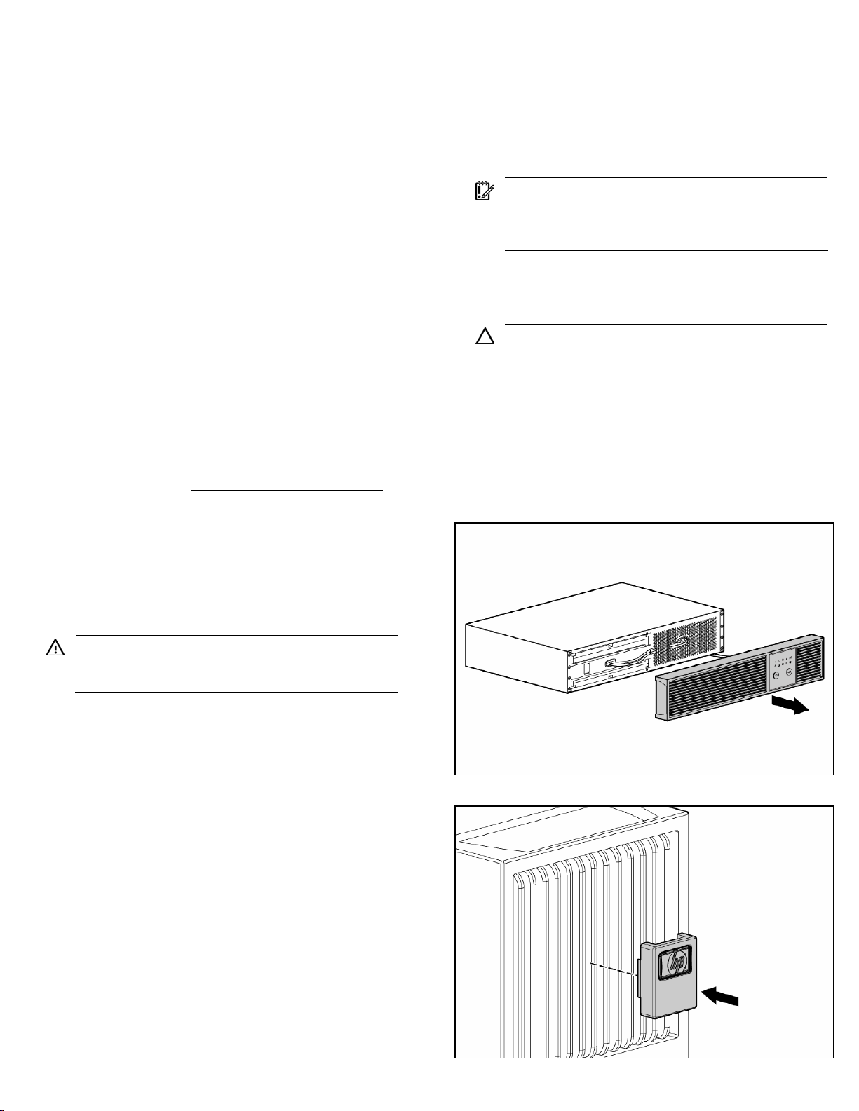
1. Remove the UPS front bezel.
2. Attach the logo badge above the LED/Control panel.
Page 3
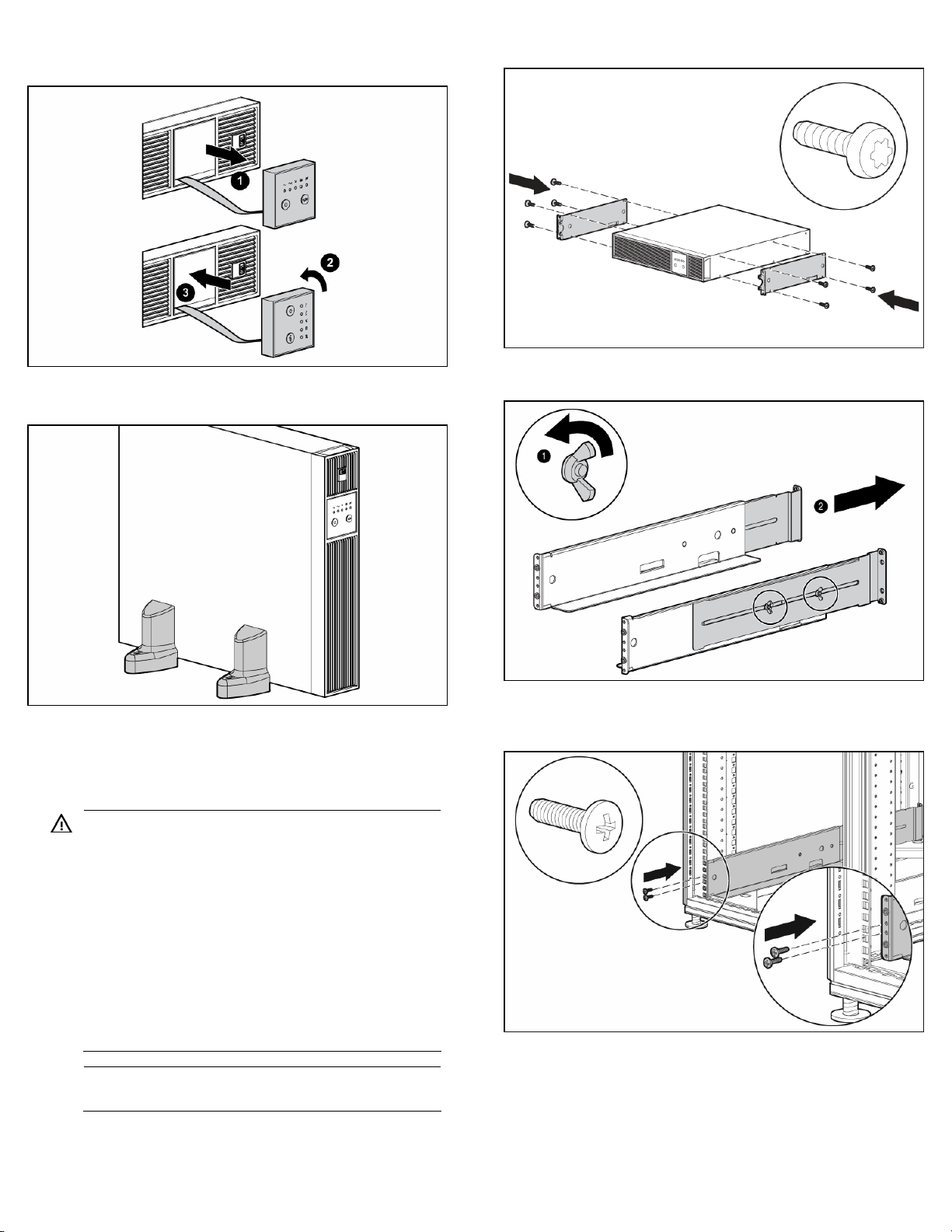
3. From inside the bezel, gently push out the LED/Control panel,
rotate it 90 degrees, and then replace it in the bezel.
4. Replace the front bezel.
5. Stand the unit on its side with the LED/Control panel at the top.
1. Attach the 2U side-mounting brackets to the unit.
2. Loosen the wing nuts, and extend the brackets to the desired
length.
Installing the UPS in a rack
Before installing the unit, review and adhere to all warnings
provided in "Precautions."
WARNING: To reduce the risk of personal injury or
damage to the equipment, be sure that:
• The leveling feet are extended to the floor.
• The full weight of the rack rests on the leveling feet.
• The stabilizing feet are attached to the rack if it is a
single-rack installation.
• The racks are coupled together in multiple-rack
installations.
• Only one component is extended at a time. A rack
may become unstable if more than one component is
extended for any reason.
NOTE: Mounting hardware for square- and round-holed
racks is included in the UPS kit.
3. Insert screws through the rack into the mounting rail and the
front of each mounting bracket. Do not completely tighten the
screws.
Page 4

4. Insert screws through the rack into the mounting rail and the
rear of each mounting bracket. Do not completely tighten the
screws.
5. Wait until the unit is installed and the brackets are adjusted
before tightening the screws.
6. Tighten the wing nuts.
WARNING: Uneven mechanical loading in the rack may
cause a hazardous condition
CAUTION: Always plan the rack installation so that the
heaviest item is on the bottom of the rack. Install the
heaviest item first, and continue to populate the rack from
the bottom to the top.
7. With one person on each side, lift the chassis to rail level and
slide the chassis on the mounting rails.
8. Attach the chassis to the rack using the supplied screws.
Connecting the batteries
WARNING: The unit contains sealed lead-acid battery
modules. To prevent fire or chemical burns:
• Do not attempt to recharge batteries after removal from
the unit.
• Do not disassemble, crush, or puncture the batteries.
• Do not short the external contacts of the batteries.
• Do not immerse the batteries in water.
• Do not expose to temperatures higher than 40°C
(104°F).
WARNING: To prevent personal injury from hazardous
energy:
• Remove watches, rings, or other metal objects.
• Use tools with insulated handles.
• Do not place tools or metal parts on top of batteries.
IMPORTANT: Before performing the following tasks, be
sure that the unit is powered down and disconnected from
the utility power source.
1. Remove the UPS front bezel.
2. Connect the battery lead to the battery terminal.
NOTE: A small amount of arcing may occur when
connecting the batteries. This is normal and does not
damage the unit or present any safety concern.
3. Replace the UPS front bezel.
4. Attach the RETMA rail covers.
NOTE: The HP logo and product name are printed on the
RETMA rail covers; therefore, the HP logo badge is only
used for a tower installation/configuration.
Page 5

Selecting the UPS voltage configuration
Using a small tool, position the DIP switches according to the desired
voltage configuration and charge rate as identified on the rear panel
of the UPS and in the following table.
When using an ERM, set the Battery Charge Level switch (DIP switch
3) to the down position, increasing the UPS charger output and
charging the ERM faster.
CAUTION: Do not set the Battery Charge Level switch to
the down position without an ERM connected. There is a
risk of damaging the internal battery system of the UPS.
NOTE: DIP switch 4 is inactive and does not affect UPS
operation regardless of the position.
CAUTION: Use only the computer interface cable supplied
with the UPS to connect the communications port to the
host computer.
CAUTION: Using a USB to serial converter cable will
damage the UPS.
Connect the UPS to a host computer using either the USB cable or
the DB9 serial cable included with the UPS. Install HP Power
Manager software 4.1 or later on the host computer. See the HP
website (http://www.hp.com/go/rackandpower
latest version of HP Power Manager.
IMPORTANT: If using HPPM, connect the Management
Server to an unswitched output receptacle, and then set
) to download the
the Management Server as the last device to shutdown,
ensuring that all connected load devices are shutdown
gracefully.
NOTE: To install and configure the software, see the
software user guide. The software user guide is available
for download from the HP website
(http://www.hp.com/go/rackandpower
).
NOTE: An asterisk (*) indicates the default setting.
R/T2200
NA/JPN/TWN
Output
voltage
120 V*
(NA)
110 V 99–
Input
voltage
range
108–
127 V
DIP
switch
1
Up Up Up* Up
Up Down — —
116 V
100 V*
(JPN/TWN)
120 V 108–
90–
106 V
Down Up — —
Down Down Down Down
127 V
R/T2200 INTL 230 V 20–
Up Up Up* Up
7243
V
230 V*
(INTL)
220 V 198–
207–
243 V
Up Down — —
Down Up — —
233 V
240 V 216–
Down Down Down Down
254 V
DIP
switch
2
DIP
switch
3
DIP
switch
4
Connecting the serial communications port
CAUTION: Use only the computer interface cable supplied
with the UPS to connect the communications port to the
host computer.
CAUTION: Using a USB to serial converter cable will
damage the UPS.
IMPORTANT: Power management software requires the
communications port to be appropriately cabled to the
host computer.
Connecting the USB communications port
CAUTION: Using a USB to serial converter cable will
damage the UPS.
Connecting the host computer
Page 6

Connecting the REPO port
WARNING: To meet the requirements stated in NEC
(NFPA 70) Articles 645-10 and 645-11, a UPS installed in
a computer equipment room must be connected to a REPO
circuit.
IMPORTANT: The remote switch must be in the Off (open)
position to enable power to the output receptacles.
Connecting the ground bonding cable
The ground bonding screw is provided as an attachment point for
conductors. Use a ground bonding cable if the rack contains any
conductors for the purpose of functional grounding or bonding of
ungrounded metal parts.
The ground bonding cable is not included.
Connecting the UPS to utility power
WARNING: To prevent injury from electric shock or
damage to the equipment:
• Plug the input line cord into a grounded (earthed)
electrical outlet that is installed near the equipment and
1. Connect the input power cord from an intended load device to
2. Connect the UPS power cord to a grounded utility power
is easily accessible.
• Do not disable the grounding plug on the input line
cord. The grounding plug is an important safety
feature.
• Do not use extension cords.
the IEC-320-C20 input power receptacle on the UPS rear panel
(INTL model only).
outlet. When the UPS is plugged in, the batteries begin to
charge. Power to the output receptacles designated for surge
and battery backup is not available until the unit is powered
up.
NOTE: Wire the connector block using stranded,
nonshielded wire (AWG #22 - #18, or equivalent).
For more information about receptacle control, see "Power
management software" in the user guide.
Connecting devices to the UPS
CAUTION: Do not plug laser printers into the UPS output
receptacles. The instantaneous current drawn by this type
of printer can overload the UPS.
Before connecting devices, verify that the UPS will not overload by
checking that the ratings of the devices do not exceed the UPS
capacity. If the equipment rating is listed in amps, multiply the
number of amps by 120 (for Japan, by 100) to determine the VA.
After verifying that the UPS will not overload:
• Connect the device power cords to the output receptacles on
the rear panel of the UPS (NA/JPN/TWN model).
-or-
• Connect devices to the output receptacles on the rear panel of
the UPS using the jumper cords included with the UPS (INTL
model).
Charging the UPS batteries
Allow the batteries to charge before putting the UPS into service.
IMPORTANT: Charge the batteries for at least 24 hours
before supplying backup power to devices. The batteries
charge to:
• 90% of their capacity within 4 hours
• 100% of their capacity within 24 hours
Page 7

Powering up the UPS
Press and hold the Power On/Standby button until the UPS beeps.
The Power LED illuminates solid green, indicating that power is
available at the UPS output receptacles.
 Loading...