

Page 1

User Service Guide
HP 9000 rp4410 and HP 9000 rp4440
Manufacturing Part Number: A9950-96011-ed4
Fourth Edition
Sept
ember 2008
© Co
pyright 2003-2008 Hewlett-Packard Development Company, L.P.
Page 2

Legal Notices
Copyright Notices. © Copyright 2003-2008 Hewlett-Packard Development Company, L.P.
The information contained herein is subject to change without notice. The only warranties for HP products
and services are set forth in the express warranty statements accompanying such products and services.
Nothing herein should be construed as constituting an additional warranty. HP shall not be liable for
technical or editorial errors or omissions contained herein.
Printed in U.S.A.
Intel, Pentium, Intel Inside, Itanium, and the Intel Inside logo are trademarks or registered trademarks of
Intel Corporation or its subsidiaries in the United States and other countries.
Linux is a U.S. registered trademark of Linus Torvalds.
2
Page 3

1. Overview
HP 9000 rp4410 and rp4440 Server Views. . . . . . . . . . . . . . . . . . . . . . . . . . . . . . . . . . . . . . . . . . . . . . . . 20
Detailed Server Description . . . . . . . . . . . . . . . . . . . . . . . . . . . . . . . . . . . . . . . . . . . . . . . . . . . . . . . . . . . 21
I/O Subsystem . . . . . . . . . . . . . . . . . . . . . . . . . . . . . . . . . . . . . . . . . . . . . . . . . . . . . . . . . . . . . . . . . . . . . 21
Processors . . . . . . . . . . . . . . . . . . . . . . . . . . . . . . . . . . . . . . . . . . . . . . . . . . . . . . . . . . . . . . . . . . . . . . . . 22
Memory . . . . . . . . . . . . . . . . . . . . . . . . . . . . . . . . . . . . . . . . . . . . . . . . . . . . . . . . . . . . . . . . . . . . . . . . . . 22
Cooling. . . . . . . . . . . . . . . . . . . . . . . . . . . . . . . . . . . . . . . . . . . . . . . . . . . . . . . . . . . . . . . . . . . . . . . . . . . 23
Power Supply Unit . . . . . . . . . . . . . . . . . . . . . . . . . . . . . . . . . . . . . . . . . . . . . . . . . . . . . . . . . . . . . . . . . 23
Front Display Panel, DVD, and Diagnostic Panel. . . . . . . . . . . . . . . . . . . . . . . . . . . . . . . . . . . . . . . . . 23
Mass Storage . . . . . . . . . . . . . . . . . . . . . . . . . . . . . . . . . . . . . . . . . . . . . . . . . . . . . . . . . . . . . . . . . . . . . . 23
Firmware. . . . . . . . . . . . . . . . . . . . . . . . . . . . . . . . . . . . . . . . . . . . . . . . . . . . . . . . . . . . . . . . . . . . . . . . . 23
Dimensions and Values . . . . . . . . . . . . . . . . . . . . . . . . . . . . . . . . . . . . . . . . . . . . . . . . . . . . . . . . . . . . . . . 24
Controls, Ports, and LEDs . . . . . . . . . . . . . . . . . . . . . . . . . . . . . . . . . . . . . . . . . . . . . . . . . . . . . . . . . . . . . 24
Front Panel . . . . . . . . . . . . . . . . . . . . . . . . . . . . . . . . . . . . . . . . . . . . . . . . . . . . . . . . . . . . . . . . . . . . . . . 24
Rear Panel. . . . . . . . . . . . . . . . . . . . . . . . . . . . . . . . . . . . . . . . . . . . . . . . . . . . . . . . . . . . . . . . . . . . . . . . 28
USB Ports . . . . . . . . . . . . . . . . . . . . . . . . . . . . . . . . . . . . . . . . . . . . . . . . . . . . . . . . . . . . . . . . . . . . . . . . 34
VGA Port . . . . . . . . . . . . . . . . . . . . . . . . . . . . . . . . . . . . . . . . . . . . . . . . . . . . . . . . . . . . . . . . . . . . . . . . . 34
Serial Ports . . . . . . . . . . . . . . . . . . . . . . . . . . . . . . . . . . . . . . . . . . . . . . . . . . . . . . . . . . . . . . . . . . . . . . . 34
iLO MP LAN Port . . . . . . . . . . . . . . . . . . . . . . . . . . . . . . . . . . . . . . . . . . . . . . . . . . . . . . . . . . . . . . . . . . 35
Gigabit Ethernet LAN Port . . . . . . . . . . . . . . . . . . . . . . . . . . . . . . . . . . . . . . . . . . . . . . . . . . . . . . . . . . 36
SCSI Port, Ultra 3, 68-Pin . . . . . . . . . . . . . . . . . . . . . . . . . . . . . . . . . . . . . . . . . . . . . . . . . . . . . . . . . . . 36
Additional Controls and LEDs. . . . . . . . . . . . . . . . . . . . . . . . . . . . . . . . . . . . . . . . . . . . . . . . . . . . . . . . 39
Powering the Server On and Off . . . . . . . . . . . . . . . . . . . . . . . . . . . . . . . . . . . . . . . . . . . . . . . . . . . . . . . . 42
Power States . . . . . . . . . . . . . . . . . . . . . . . . . . . . . . . . . . . . . . . . . . . . . . . . . . . . . . . . . . . . . . . . . . . . . . 42
Powering On the Server . . . . . . . . . . . . . . . . . . . . . . . . . . . . . . . . . . . . . . . . . . . . . . . . . . . . . . . . . . . . . 43
Powering Off the Server . . . . . . . . . . . . . . . . . . . . . . . . . . . . . . . . . . . . . . . . . . . . . . . . . . . . . . . . . . . . . 44
Contents
2. System Specifications
System Configuration . . . . . . . . . . . . . . . . . . . . . . . . . . . . . . . . . . . . . . . . . . . . . . . . . . . . . . . . . . . . . . . . 45
Dimensions and Values . . . . . . . . . . . . . . . . . . . . . . . . . . . . . . . . . . . . . . . . . . . . . . . . . . . . . . . . . . . . . . . 46
Grounding. . . . . . . . . . . . . . . . . . . . . . . . . . . . . . . . . . . . . . . . . . . . . . . . . . . . . . . . . . . . . . . . . . . . . . . . . . 46
Electrical Specifications. . . . . . . . . . . . . . . . . . . . . . . . . . . . . . . . . . . . . . . . . . . . . . . . . . . . . . . . . . . . . . . 47
AC Power Cords . . . . . . . . . . . . . . . . . . . . . . . . . . . . . . . . . . . . . . . . . . . . . . . . . . . . . . . . . . . . . . . . . . . 47
Circuit Breaker . . . . . . . . . . . . . . . . . . . . . . . . . . . . . . . . . . . . . . . . . . . . . . . . . . . . . . . . . . . . . . . . . . . . 47
System Power Specifications . . . . . . . . . . . . . . . . . . . . . . . . . . . . . . . . . . . . . . . . . . . . . . . . . . . . . . . . . 47
Power and Cooling . . . . . . . . . . . . . . . . . . . . . . . . . . . . . . . . . . . . . . . . . . . . . . . . . . . . . . . . . . . . . . . . . 49
Environmental Specifications . . . . . . . . . . . . . . . . . . . . . . . . . . . . . . . . . . . . . . . . . . . . . . . . . . . . . . . . . . 50
Operating Environment . . . . . . . . . . . . . . . . . . . . . . . . . . . . . . . . . . . . . . . . . . . . . . . . . . . . . . . . . . . . . 50
Environmental Temperature Sensor . . . . . . . . . . . . . . . . . . . . . . . . . . . . . . . . . . . . . . . . . . . . . . . . . . . 50
Nonoperating Environment . . . . . . . . . . . . . . . . . . . . . . . . . . . . . . . . . . . . . . . . . . . . . . . . . . . . . . . . . . 50
Cooling. . . . . . . . . . . . . . . . . . . . . . . . . . . . . . . . . . . . . . . . . . . . . . . . . . . . . . . . . . . . . . . . . . . . . . . . . . . 51
Acoustic Noise Specification. . . . . . . . . . . . . . . . . . . . . . . . . . . . . . . . . . . . . . . . . . . . . . . . . . . . . . . . . . 52
Physical and Environmental Specifications . . . . . . . . . . . . . . . . . . . . . . . . . . . . . . . . . . . . . . . . . . . . . . . 53
3. Installing the System
Introduction . . . . . . . . . . . . . . . . . . . . . . . . . . . . . . . . . . . . . . . . . . . . . . . . . . . . . . . . . . . . . . . . . . . . . . . . 55
3
Page 4

Contents
Server Views. . . . . . . . . . . . . . . . . . . . . . . . . . . . . . . . . . . . . . . . . . . . . . . . . . . . . . . . . . . . . . . . . . . . . . . . 56
Detailed Server Description . . . . . . . . . . . . . . . . . . . . . . . . . . . . . . . . . . . . . . . . . . . . . . . . . . . . . . . . . . . 57
I/O Subsystem . . . . . . . . . . . . . . . . . . . . . . . . . . . . . . . . . . . . . . . . . . . . . . . . . . . . . . . . . . . . . . . . . . . . . 57
Processors . . . . . . . . . . . . . . . . . . . . . . . . . . . . . . . . . . . . . . . . . . . . . . . . . . . . . . . . . . . . . . . . . . . . . . . . 58
Memory . . . . . . . . . . . . . . . . . . . . . . . . . . . . . . . . . . . . . . . . . . . . . . . . . . . . . . . . . . . . . . . . . . . . . . . . . . 58
Cooling. . . . . . . . . . . . . . . . . . . . . . . . . . . . . . . . . . . . . . . . . . . . . . . . . . . . . . . . . . . . . . . . . . . . . . . . . . . 59
Power Supply Unit . . . . . . . . . . . . . . . . . . . . . . . . . . . . . . . . . . . . . . . . . . . . . . . . . . . . . . . . . . . . . . . . . 59
Front Display Panel, DVD, and Diagnostic Panel. . . . . . . . . . . . . . . . . . . . . . . . . . . . . . . . . . . . . . . . . 59
Mass Storage . . . . . . . . . . . . . . . . . . . . . . . . . . . . . . . . . . . . . . . . . . . . . . . . . . . . . . . . . . . . . . . . . . . . . . 59
Firmware. . . . . . . . . . . . . . . . . . . . . . . . . . . . . . . . . . . . . . . . . . . . . . . . . . . . . . . . . . . . . . . . . . . . . . . . . 59
Dimensions and Values . . . . . . . . . . . . . . . . . . . . . . . . . . . . . . . . . . . . . . . . . . . . . . . . . . . . . . . . . . . . . 60
Safety Information . . . . . . . . . . . . . . . . . . . . . . . . . . . . . . . . . . . . . . . . . . . . . . . . . . . . . . . . . . . . . . . . . . . 60
Installation Sequence and Checklist. . . . . . . . . . . . . . . . . . . . . . . . . . . . . . . . . . . . . . . . . . . . . . . . . . . . . 61
Unpacking and Inspecting the Server . . . . . . . . . . . . . . . . . . . . . . . . . . . . . . . . . . . . . . . . . . . . . . . . . . . 62
Verifying Site Preparation . . . . . . . . . . . . . . . . . . . . . . . . . . . . . . . . . . . . . . . . . . . . . . . . . . . . . . . . . . . 62
Inspecting the Shipping Containers for Damage . . . . . . . . . . . . . . . . . . . . . . . . . . . . . . . . . . . . . . . . . 62
Unpacking the Server . . . . . . . . . . . . . . . . . . . . . . . . . . . . . . . . . . . . . . . . . . . . . . . . . . . . . . . . . . . . . . . 62
Checking the Inventory . . . . . . . . . . . . . . . . . . . . . . . . . . . . . . . . . . . . . . . . . . . . . . . . . . . . . . . . . . . . . 62
Returning Damaged Equipment . . . . . . . . . . . . . . . . . . . . . . . . . . . . . . . . . . . . . . . . . . . . . . . . . . . . . . 63
Unloading the Server with a Lifter . . . . . . . . . . . . . . . . . . . . . . . . . . . . . . . . . . . . . . . . . . . . . . . . . . . . 63
Installing Additional Components . . . . . . . . . . . . . . . . . . . . . . . . . . . . . . . . . . . . . . . . . . . . . . . . . . . . . . 63
Service Tools Required . . . . . . . . . . . . . . . . . . . . . . . . . . . . . . . . . . . . . . . . . . . . . . . . . . . . . . . . . . . . . . 63
Accessing a Rack-Mounted Server . . . . . . . . . . . . . . . . . . . . . . . . . . . . . . . . . . . . . . . . . . . . . . . . . . . . . 64
Accessing a Pedestal-Mounted Server . . . . . . . . . . . . . . . . . . . . . . . . . . . . . . . . . . . . . . . . . . . . . . . . . . 65
Front Panel Controls and Indicators . . . . . . . . . . . . . . . . . . . . . . . . . . . . . . . . . . . . . . . . . . . . . . . . . . . 66
Additional Controls and Indicators . . . . . . . . . . . . . . . . . . . . . . . . . . . . . . . . . . . . . . . . . . . . . . . . . . . . 70
Front Bezel . . . . . . . . . . . . . . . . . . . . . . . . . . . . . . . . . . . . . . . . . . . . . . . . . . . . . . . . . . . . . . . . . . . . . . . 71
Front and Top Covers . . . . . . . . . . . . . . . . . . . . . . . . . . . . . . . . . . . . . . . . . . . . . . . . . . . . . . . . . . . . . . . 72
Hot-Swappable Chassis Fan Units . . . . . . . . . . . . . . . . . . . . . . . . . . . . . . . . . . . . . . . . . . . . . . . . . . . . 75
I/O Baseboard Assembly. . . . . . . . . . . . . . . . . . . . . . . . . . . . . . . . . . . . . . . . . . . . . . . . . . . . . . . . . . . . . 77
System Battery . . . . . . . . . . . . . . . . . . . . . . . . . . . . . . . . . . . . . . . . . . . . . . . . . . . . . . . . . . . . . . . . . . . . 81
Installing Power Supplies and Disk Drives. . . . . . . . . . . . . . . . . . . . . . . . . . . . . . . . . . . . . . . . . . . . . . 83
Installing Processors. . . . . . . . . . . . . . . . . . . . . . . . . . . . . . . . . . . . . . . . . . . . . . . . . . . . . . . . . . . . . . . . 86
Installing Memory . . . . . . . . . . . . . . . . . . . . . . . . . . . . . . . . . . . . . . . . . . . . . . . . . . . . . . . . . . . . . . . . . 94
Hot-Pluggable PCI/PCI-X . . . . . . . . . . . . . . . . . . . . . . . . . . . . . . . . . . . . . . . . . . . . . . . . . . . . . . . . . . . 100
Converting SCSI From Simplex to Duplex . . . . . . . . . . . . . . . . . . . . . . . . . . . . . . . . . . . . . . . . . . . . . 109
Installing the Server Into a Rack, Non-HP rack, or Pedestal . . . . . . . . . . . . . . . . . . . . . . . . . . . . . . . . 115
HP Rack. . . . . . . . . . . . . . . . . . . . . . . . . . . . . . . . . . . . . . . . . . . . . . . . . . . . . . . . . . . . . . . . . . . . . . . . . 115
Non-HP Rack. . . . . . . . . . . . . . . . . . . . . . . . . . . . . . . . . . . . . . . . . . . . . . . . . . . . . . . . . . . . . . . . . . . . . 115
Pedestal Mount . . . . . . . . . . . . . . . . . . . . . . . . . . . . . . . . . . . . . . . . . . . . . . . . . . . . . . . . . . . . . . . . . . . 115
Connecting the Cables . . . . . . . . . . . . . . . . . . . . . . . . . . . . . . . . . . . . . . . . . . . . . . . . . . . . . . . . . . . . . . . 116
AC Input Power. . . . . . . . . . . . . . . . . . . . . . . . . . . . . . . . . . . . . . . . . . . . . . . . . . . . . . . . . . . . . . . . . . . 116
Core I/O Connections . . . . . . . . . . . . . . . . . . . . . . . . . . . . . . . . . . . . . . . . . . . . . . . . . . . . . . . . . . . . . . 116
Applying Standby Power to the Server . . . . . . . . . . . . . . . . . . . . . . . . . . . . . . . . . . . . . . . . . . . . . . . . 117
Connecting to the LAN . . . . . . . . . . . . . . . . . . . . . . . . . . . . . . . . . . . . . . . . . . . . . . . . . . . . . . . . . . . . . 117
Console Setup . . . . . . . . . . . . . . . . . . . . . . . . . . . . . . . . . . . . . . . . . . . . . . . . . . . . . . . . . . . . . . . . . . . . . . 118
4
Page 5

Contents
Setting Up the Console . . . . . . . . . . . . . . . . . . . . . . . . . . . . . . . . . . . . . . . . . . . . . . . . . . . . . . . . . . . . . 118
Setup Checklist . . . . . . . . . . . . . . . . . . . . . . . . . . . . . . . . . . . . . . . . . . . . . . . . . . . . . . . . . . . . . . . . . . . 119
Setup Flowchart . . . . . . . . . . . . . . . . . . . . . . . . . . . . . . . . . . . . . . . . . . . . . . . . . . . . . . . . . . . . . . . . . . 120
Preparation . . . . . . . . . . . . . . . . . . . . . . . . . . . . . . . . . . . . . . . . . . . . . . . . . . . . . . . . . . . . . . . . . . . . . . 121
Configuring the iLO MP LAN Using DHCP and DNS . . . . . . . . . . . . . . . . . . . . . . . . . . . . . . . . . . . . 122
Configuring the iLO MP LAN Using ARP Ping . . . . . . . . . . . . . . . . . . . . . . . . . . . . . . . . . . . . . . . . . 122
Configuring the iLO MP LAN Using the RS-232 Serial Port. . . . . . . . . . . . . . . . . . . . . . . . . . . . . . . 124
Logging In to the iLO MP. . . . . . . . . . . . . . . . . . . . . . . . . . . . . . . . . . . . . . . . . . . . . . . . . . . . . . . . . . . 125
Additional Setup . . . . . . . . . . . . . . . . . . . . . . . . . . . . . . . . . . . . . . . . . . . . . . . . . . . . . . . . . . . . . . . . . . 126
Accessing the Host Console . . . . . . . . . . . . . . . . . . . . . . . . . . . . . . . . . . . . . . . . . . . . . . . . . . . . . . . . . . . 127
Accessing the Host Console With the TUI - CO Command . . . . . . . . . . . . . . . . . . . . . . . . . . . . . . . . 127
Interacting with the iLO MP Using the Web GUI . . . . . . . . . . . . . . . . . . . . . . . . . . . . . . . . . . . . . . . 127
Accessing the Graphic Console Using VGA. . . . . . . . . . . . . . . . . . . . . . . . . . . . . . . . . . . . . . . . . . . . . 129
Powering the Server ON and Off. . . . . . . . . . . . . . . . . . . . . . . . . . . . . . . . . . . . . . . . . . . . . . . . . . . . . . . 131
Power States . . . . . . . . . . . . . . . . . . . . . . . . . . . . . . . . . . . . . . . . . . . . . . . . . . . . . . . . . . . . . . . . . . . . . 131
Powering On the Server . . . . . . . . . . . . . . . . . . . . . . . . . . . . . . . . . . . . . . . . . . . . . . . . . . . . . . . . . . . . 131
Powering Off the Server . . . . . . . . . . . . . . . . . . . . . . . . . . . . . . . . . . . . . . . . . . . . . . . . . . . . . . . . . . . . 132
Booting the Operating System . . . . . . . . . . . . . . . . . . . . . . . . . . . . . . . . . . . . . . . . . . . . . . . . . . . . . . . . 134
Supported Operating System . . . . . . . . . . . . . . . . . . . . . . . . . . . . . . . . . . . . . . . . . . . . . . . . . . . . . . . . 134
Booting and Shutting Down HP-UX . . . . . . . . . . . . . . . . . . . . . . . . . . . . . . . . . . . . . . . . . . . . . . . . . . 134
Verifying the Server Configuration Using Boot Console Handler . . . . . . . . . . . . . . . . . . . . . . . . . . . 135
Troubleshooting . . . . . . . . . . . . . . . . . . . . . . . . . . . . . . . . . . . . . . . . . . . . . . . . . . . . . . . . . . . . . . . . . . . . 136
Troubleshooting Methodology . . . . . . . . . . . . . . . . . . . . . . . . . . . . . . . . . . . . . . . . . . . . . . . . . . . . . . . 136
Troubleshooting Using the Server Power Button . . . . . . . . . . . . . . . . . . . . . . . . . . . . . . . . . . . . . . . . 136
Server Does Not Power On . . . . . . . . . . . . . . . . . . . . . . . . . . . . . . . . . . . . . . . . . . . . . . . . . . . . . . . . . . 137
BCH Menu is Not Available . . . . . . . . . . . . . . . . . . . . . . . . . . . . . . . . . . . . . . . . . . . . . . . . . . . . . . . . . 138
Operating System Does Not Boot . . . . . . . . . . . . . . . . . . . . . . . . . . . . . . . . . . . . . . . . . . . . . . . . . . . . 138
Operating System Boots with Problems . . . . . . . . . . . . . . . . . . . . . . . . . . . . . . . . . . . . . . . . . . . . . . . 138
Intermittent Server Problems . . . . . . . . . . . . . . . . . . . . . . . . . . . . . . . . . . . . . . . . . . . . . . . . . . . . . . . 138
DVD Problems. . . . . . . . . . . . . . . . . . . . . . . . . . . . . . . . . . . . . . . . . . . . . . . . . . . . . . . . . . . . . . . . . . . . 139
Hard Drive Problems . . . . . . . . . . . . . . . . . . . . . . . . . . . . . . . . . . . . . . . . . . . . . . . . . . . . . . . . . . . . . . 139
Console Problems . . . . . . . . . . . . . . . . . . . . . . . . . . . . . . . . . . . . . . . . . . . . . . . . . . . . . . . . . . . . . . . . . 139
Downloading and Installing the Latest Version of the Firmware . . . . . . . . . . . . . . . . . . . . . . . . . . . 139
Troubleshooting Using LED Indicators. . . . . . . . . . . . . . . . . . . . . . . . . . . . . . . . . . . . . . . . . . . . . . . . 140
Information to Collect Before You Contact Support . . . . . . . . . . . . . . . . . . . . . . . . . . . . . . . . . . . . . . 144
4. Booting the Operating System
Supported Operating System . . . . . . . . . . . . . . . . . . . . . . . . . . . . . . . . . . . . . . . . . . . . . . . . . . . . . . . . . 145
Booting and Shutting Down HP-UX . . . . . . . . . . . . . . . . . . . . . . . . . . . . . . . . . . . . . . . . . . . . . . . . . . . . 146
Standard HP-UX Booting Using Boot Console Handler. . . . . . . . . . . . . . . . . . . . . . . . . . . . . . . . . . . 146
Booting HP-UX in Single-User Mode . . . . . . . . . . . . . . . . . . . . . . . . . . . . . . . . . . . . . . . . . . . . . . . . . 147
Booting HP-UX in LVM Maintenance Mode . . . . . . . . . . . . . . . . . . . . . . . . . . . . . . . . . . . . . . . . . . . . 147
Shutting Down HP-UX . . . . . . . . . . . . . . . . . . . . . . . . . . . . . . . . . . . . . . . . . . . . . . . . . . . . . . . . . . . . . 147
Verifying the Server Configuration Using Boot Console Handler. . . . . . . . . . . . . . . . . . . . . . . . . . . . . 148
5. Troubleshooting
5
Page 6

Contents
Troubleshooting Methodology . . . . . . . . . . . . . . . . . . . . . . . . . . . . . . . . . . . . . . . . . . . . . . . . . . . . . . . . . 149
Troubleshooting System Power . . . . . . . . . . . . . . . . . . . . . . . . . . . . . . . . . . . . . . . . . . . . . . . . . . . . . . . . 150
Using the Front Panel Power Button. . . . . . . . . . . . . . . . . . . . . . . . . . . . . . . . . . . . . . . . . . . . . . . . . . 150
System Does Not Successfully Power On and Remain Powered On . . . . . . . . . . . . . . . . . . . . . . . . . 150
Operating System Boots. . . . . . . . . . . . . . . . . . . . . . . . . . . . . . . . . . . . . . . . . . . . . . . . . . . . . . . . . . . . 155
Operating System Does Not Boot . . . . . . . . . . . . . . . . . . . . . . . . . . . . . . . . . . . . . . . . . . . . . . . . . . . . 155
Troubleshooting Using Online Support Tools . . . . . . . . . . . . . . . . . . . . . . . . . . . . . . . . . . . . . . . . . . . . 155
Support Tools Manager . . . . . . . . . . . . . . . . . . . . . . . . . . . . . . . . . . . . . . . . . . . . . . . . . . . . . . . . . . . . 155
Event Monitoring Service . . . . . . . . . . . . . . . . . . . . . . . . . . . . . . . . . . . . . . . . . . . . . . . . . . . . . . . . . . . 156
iLO MP . . . . . . . . . . . . . . . . . . . . . . . . . . . . . . . . . . . . . . . . . . . . . . . . . . . . . . . . . . . . . . . . . . . . . . . . . 156
Troubleshooting Using Offline Support Tools . . . . . . . . . . . . . . . . . . . . . . . . . . . . . . . . . . . . . . . . . . . . 158
ODE . . . . . . . . . . . . . . . . . . . . . . . . . . . . . . . . . . . . . . . . . . . . . . . . . . . . . . . . . . . . . . . . . . . . . . . . . . . . 158
Troubleshooting PCI/PCI-X Hot-Pluggable Operations . . . . . . . . . . . . . . . . . . . . . . . . . . . . . . . . . . . 160
Troubleshooting Using LED Indicators . . . . . . . . . . . . . . . . . . . . . . . . . . . . . . . . . . . . . . . . . . . . . . . . . 161
Front Control Panel LEDs . . . . . . . . . . . . . . . . . . . . . . . . . . . . . . . . . . . . . . . . . . . . . . . . . . . . . . . . . . 161
QuickFind Diagnostic Panel LEDs . . . . . . . . . . . . . . . . . . . . . . . . . . . . . . . . . . . . . . . . . . . . . . . . . . . 163
I/O Baseboard LED Indicators . . . . . . . . . . . . . . . . . . . . . . . . . . . . . . . . . . . . . . . . . . . . . . . . . . . . . . . 165
Memory Extender Boards. . . . . . . . . . . . . . . . . . . . . . . . . . . . . . . . . . . . . . . . . . . . . . . . . . . . . . . . . . . 166
Disk and I/O Path Logging . . . . . . . . . . . . . . . . . . . . . . . . . . . . . . . . . . . . . . . . . . . . . . . . . . . . . . . . . . . 169
Core I/O Connections . . . . . . . . . . . . . . . . . . . . . . . . . . . . . . . . . . . . . . . . . . . . . . . . . . . . . . . . . . . . . . . . 171
System I/O Board Switches and Jumpers. . . . . . . . . . . . . . . . . . . . . . . . . . . . . . . . . . . . . . . . . . . . . . . . 172
6. Removing and Replacing Components
Safety Information . . . . . . . . . . . . . . . . . . . . . . . . . . . . . . . . . . . . . . . . . . . . . . . . . . . . . . . . . . . . . . . . . . 176
Required Service Tools. . . . . . . . . . . . . . . . . . . . . . . . . . . . . . . . . . . . . . . . . . . . . . . . . . . . . . . . . . . . . . . 176
Accessing a Rack-Mounted Server . . . . . . . . . . . . . . . . . . . . . . . . . . . . . . . . . . . . . . . . . . . . . . . . . . . . . 177
Extend the Server from the Rack. . . . . . . . . . . . . . . . . . . . . . . . . . . . . . . . . . . . . . . . . . . . . . . . . . . . . 177
Inserting the Server Into the Rack . . . . . . . . . . . . . . . . . . . . . . . . . . . . . . . . . . . . . . . . . . . . . . . . . . . 178
Accessing a Pedestal-Mounted Server . . . . . . . . . . . . . . . . . . . . . . . . . . . . . . . . . . . . . . . . . . . . . . . . . . 178
Front Bezel . . . . . . . . . . . . . . . . . . . . . . . . . . . . . . . . . . . . . . . . . . . . . . . . . . . . . . . . . . . . . . . . . . . . . . . . 180
Removing the Front Bezel . . . . . . . . . . . . . . . . . . . . . . . . . . . . . . . . . . . . . . . . . . . . . . . . . . . . . . . . . . 180
Replacing the Front Bezel . . . . . . . . . . . . . . . . . . . . . . . . . . . . . . . . . . . . . . . . . . . . . . . . . . . . . . . . . . 180
Front and Top Covers . . . . . . . . . . . . . . . . . . . . . . . . . . . . . . . . . . . . . . . . . . . . . . . . . . . . . . . . . . . . . . . 181
Removing the Front Cover . . . . . . . . . . . . . . . . . . . . . . . . . . . . . . . . . . . . . . . . . . . . . . . . . . . . . . . . . . 181
Replacing the Front Cover . . . . . . . . . . . . . . . . . . . . . . . . . . . . . . . . . . . . . . . . . . . . . . . . . . . . . . . . . . 182
Removing the Top Cover. . . . . . . . . . . . . . . . . . . . . . . . . . . . . . . . . . . . . . . . . . . . . . . . . . . . . . . . . . . . 182
Replacing the Top Cover. . . . . . . . . . . . . . . . . . . . . . . . . . . . . . . . . . . . . . . . . . . . . . . . . . . . . . . . . . . . 183
Memory Extender Board . . . . . . . . . . . . . . . . . . . . . . . . . . . . . . . . . . . . . . . . . . . . . . . . . . . . . . . . . . . . . 184
Removing a Memory Extender Board . . . . . . . . . . . . . . . . . . . . . . . . . . . . . . . . . . . . . . . . . . . . . . . . . 184
Replacing the Memory Extender Board . . . . . . . . . . . . . . . . . . . . . . . . . . . . . . . . . . . . . . . . . . . . . . . 186
System Memory DIMMs . . . . . . . . . . . . . . . . . . . . . . . . . . . . . . . . . . . . . . . . . . . . . . . . . . . . . . . . . . . . . 187
Replacing Deallocated Memory Ranks . . . . . . . . . . . . . . . . . . . . . . . . . . . . . . . . . . . . . . . . . . . . . . . . 187
Removing Memory DIMMs . . . . . . . . . . . . . . . . . . . . . . . . . . . . . . . . . . . . . . . . . . . . . . . . . . . . . . . . . 187
Installing Memory DIMMs. . . . . . . . . . . . . . . . . . . . . . . . . . . . . . . . . . . . . . . . . . . . . . . . . . . . . . . . . . 188
Processor Extender Board . . . . . . . . . . . . . . . . . . . . . . . . . . . . . . . . . . . . . . . . . . . . . . . . . . . . . . . . . . . . 192
Removing the Processor Extender Board . . . . . . . . . . . . . . . . . . . . . . . . . . . . . . . . . . . . . . . . . . . . . . 192
6
Page 7

Contents
Replacing the Processor Extender Board . . . . . . . . . . . . . . . . . . . . . . . . . . . . . . . . . . . . . . . . . . . . . . 194
Replacing Dual Processor Modules . . . . . . . . . . . . . . . . . . . . . . . . . . . . . . . . . . . . . . . . . . . . . . . . . . . . . 196
Dual Processor Modules . . . . . . . . . . . . . . . . . . . . . . . . . . . . . . . . . . . . . . . . . . . . . . . . . . . . . . . . . . . . 196
Processor Load Order . . . . . . . . . . . . . . . . . . . . . . . . . . . . . . . . . . . . . . . . . . . . . . . . . . . . . . . . . . . . . . 196
Removing a Dual Processor Module . . . . . . . . . . . . . . . . . . . . . . . . . . . . . . . . . . . . . . . . . . . . . . . . . . 197
Installing a Dual Processor Module. . . . . . . . . . . . . . . . . . . . . . . . . . . . . . . . . . . . . . . . . . . . . . . . . . . 199
Hot-Swappable Chassis Fan Unit . . . . . . . . . . . . . . . . . . . . . . . . . . . . . . . . . . . . . . . . . . . . . . . . . . . . . . 203
Removing a Hot-Swappable Chassis Fan Unit . . . . . . . . . . . . . . . . . . . . . . . . . . . . . . . . . . . . . . . . . . 203
Replacing a Hot-Swappable Chassis Fan Unit . . . . . . . . . . . . . . . . . . . . . . . . . . . . . . . . . . . . . . . . . . 206
I/O Baseboard Assembly . . . . . . . . . . . . . . . . . . . . . . . . . . . . . . . . . . . . . . . . . . . . . . . . . . . . . . . . . . . . . 206
Removing the I/O Baseboard Assembly. . . . . . . . . . . . . . . . . . . . . . . . . . . . . . . . . . . . . . . . . . . . . . . . 207
Replacing the I/O Baseboard Assembly. . . . . . . . . . . . . . . . . . . . . . . . . . . . . . . . . . . . . . . . . . . . . . . . 209
Removing and Replacing the I/O Baseboard Locking Lever . . . . . . . . . . . . . . . . . . . . . . . . . . . . . . . 213
System Battery. . . . . . . . . . . . . . . . . . . . . . . . . . . . . . . . . . . . . . . . . . . . . . . . . . . . . . . . . . . . . . . . . . . . . 213
Battery Notice . . . . . . . . . . . . . . . . . . . . . . . . . . . . . . . . . . . . . . . . . . . . . . . . . . . . . . . . . . . . . . . . . . . . 213
Replacing the System Battery . . . . . . . . . . . . . . . . . . . . . . . . . . . . . . . . . . . . . . . . . . . . . . . . . . . . . . . 214
Removing and Replacing PCI/PCI-X Cards . . . . . . . . . . . . . . . . . . . . . . . . . . . . . . . . . . . . . . . . . . . . . . 216
PCI/PCI-X Configurations . . . . . . . . . . . . . . . . . . . . . . . . . . . . . . . . . . . . . . . . . . . . . . . . . . . . . . . . . . 217
OLA . . . . . . . . . . . . . . . . . . . . . . . . . . . . . . . . . . . . . . . . . . . . . . . . . . . . . . . . . . . . . . . . . . . . . . . . . . . . 220
OLR . . . . . . . . . . . . . . . . . . . . . . . . . . . . . . . . . . . . . . . . . . . . . . . . . . . . . . . . . . . . . . . . . . . . . . . . . . . . 225
Removing a PCI/PCI-X Card Offline . . . . . . . . . . . . . . . . . . . . . . . . . . . . . . . . . . . . . . . . . . . . . . . . . . 226
Installing a PCI Card Offline . . . . . . . . . . . . . . . . . . . . . . . . . . . . . . . . . . . . . . . . . . . . . . . . . . . . . . . . 227
OLX Dividers . . . . . . . . . . . . . . . . . . . . . . . . . . . . . . . . . . . . . . . . . . . . . . . . . . . . . . . . . . . . . . . . . . . . . . 228
Removing an OLX Divider . . . . . . . . . . . . . . . . . . . . . . . . . . . . . . . . . . . . . . . . . . . . . . . . . . . . . . . . . . 228
Replacing an OLX Divider . . . . . . . . . . . . . . . . . . . . . . . . . . . . . . . . . . . . . . . . . . . . . . . . . . . . . . . . . . 231
U320 SCSI Enablement and Conversion Procedures . . . . . . . . . . . . . . . . . . . . . . . . . . . . . . . . . . . . . . 231
Time Required. . . . . . . . . . . . . . . . . . . . . . . . . . . . . . . . . . . . . . . . . . . . . . . . . . . . . . . . . . . . . . . . . . . . 231
Upgrade Tasks . . . . . . . . . . . . . . . . . . . . . . . . . . . . . . . . . . . . . . . . . . . . . . . . . . . . . . . . . . . . . . . . . . . 232
Back Up Your System . . . . . . . . . . . . . . . . . . . . . . . . . . . . . . . . . . . . . . . . . . . . . . . . . . . . . . . . . . . . . . 232
Removing Server Components . . . . . . . . . . . . . . . . . . . . . . . . . . . . . . . . . . . . . . . . . . . . . . . . . . . . . . . 232
Removing the SCSI Duplex Board. . . . . . . . . . . . . . . . . . . . . . . . . . . . . . . . . . . . . . . . . . . . . . . . . . . . 233
Removing the SCSI Backplane . . . . . . . . . . . . . . . . . . . . . . . . . . . . . . . . . . . . . . . . . . . . . . . . . . . . . . 235
Replacing the SCSI Backplane . . . . . . . . . . . . . . . . . . . . . . . . . . . . . . . . . . . . . . . . . . . . . . . . . . . . . . 237
Installing the SCSI Duplex Board . . . . . . . . . . . . . . . . . . . . . . . . . . . . . . . . . . . . . . . . . . . . . . . . . . . . 238
Installing the Server Components . . . . . . . . . . . . . . . . . . . . . . . . . . . . . . . . . . . . . . . . . . . . . . . . . . . . 239
Verify the Upgrade Installation . . . . . . . . . . . . . . . . . . . . . . . . . . . . . . . . . . . . . . . . . . . . . . . . . . . . . . 240
Converting SCSI From Duplex to Simplex Operation . . . . . . . . . . . . . . . . . . . . . . . . . . . . . . . . . . . . 240
Removing and Replacing Core I/O Cards . . . . . . . . . . . . . . . . . . . . . . . . . . . . . . . . . . . . . . . . . . . . . . . . 245
Safety Information . . . . . . . . . . . . . . . . . . . . . . . . . . . . . . . . . . . . . . . . . . . . . . . . . . . . . . . . . . . . . . . . 245
Required Service Tools . . . . . . . . . . . . . . . . . . . . . . . . . . . . . . . . . . . . . . . . . . . . . . . . . . . . . . . . . . . . . 245
PCI Slot Locations and Configurations . . . . . . . . . . . . . . . . . . . . . . . . . . . . . . . . . . . . . . . . . . . . . . . . 246
Removing the LAN Core I/O Card . . . . . . . . . . . . . . . . . . . . . . . . . . . . . . . . . . . . . . . . . . . . . . . . . . . . 246
Installing the LAN Core I/O Card . . . . . . . . . . . . . . . . . . . . . . . . . . . . . . . . . . . . . . . . . . . . . . . . . . . . 247
Removing the SCSI Core I/O Card . . . . . . . . . . . . . . . . . . . . . . . . . . . . . . . . . . . . . . . . . . . . . . . . . . . 247
Hot-Pluggable Disk Drives . . . . . . . . . . . . . . . . . . . . . . . . . . . . . . . . . . . . . . . . . . . . . . . . . . . . . . . . . . . 250
Removing a Hot-Pluggable Disk Drive . . . . . . . . . . . . . . . . . . . . . . . . . . . . . . . . . . . . . . . . . . . . . . . . 250
7
Page 8

Contents
Replacing a Hot-Pluggable Disk Drive . . . . . . . . . . . . . . . . . . . . . . . . . . . . . . . . . . . . . . . . . . . . . . . . 250
SCSI Backplane . . . . . . . . . . . . . . . . . . . . . . . . . . . . . . . . . . . . . . . . . . . . . . . . . . . . . . . . . . . . . . . . . . . . 252
Removing the SCSI Backplane . . . . . . . . . . . . . . . . . . . . . . . . . . . . . . . . . . . . . . . . . . . . . . . . . . . . . . 253
Replacing the SCSI Backplane . . . . . . . . . . . . . . . . . . . . . . . . . . . . . . . . . . . . . . . . . . . . . . . . . . . . . . 254
Midplane Riser Board . . . . . . . . . . . . . . . . . . . . . . . . . . . . . . . . . . . . . . . . . . . . . . . . . . . . . . . . . . . . . . . 255
Removing the Midplane Riser Board. . . . . . . . . . . . . . . . . . . . . . . . . . . . . . . . . . . . . . . . . . . . . . . . . . 255
Replacing the Midplane Riser Board. . . . . . . . . . . . . . . . . . . . . . . . . . . . . . . . . . . . . . . . . . . . . . . . . . 258
Hot-Swappable Power Supplies. . . . . . . . . . . . . . . . . . . . . . . . . . . . . . . . . . . . . . . . . . . . . . . . . . . . . . . . 258
Power Supply Load Order . . . . . . . . . . . . . . . . . . . . . . . . . . . . . . . . . . . . . . . . . . . . . . . . . . . . . . . . . . 259
Removing a Hot-Swappable Power Supply . . . . . . . . . . . . . . . . . . . . . . . . . . . . . . . . . . . . . . . . . . . . . 259
Replacing a Hot-Swappable Power Supply . . . . . . . . . . . . . . . . . . . . . . . . . . . . . . . . . . . . . . . . . . . . . 260
Power Distribution Board . . . . . . . . . . . . . . . . . . . . . . . . . . . . . . . . . . . . . . . . . . . . . . . . . . . . . . . . . . . . 261
Removing the Power Distribution Board. . . . . . . . . . . . . . . . . . . . . . . . . . . . . . . . . . . . . . . . . . . . . . . 261
Replacing the Power Distribution Board. . . . . . . . . . . . . . . . . . . . . . . . . . . . . . . . . . . . . . . . . . . . . . . 262
DVD Drive . . . . . . . . . . . . . . . . . . . . . . . . . . . . . . . . . . . . . . . . . . . . . . . . . . . . . . . . . . . . . . . . . . . . . . . . 263
Removing a DVD Drive . . . . . . . . . . . . . . . . . . . . . . . . . . . . . . . . . . . . . . . . . . . . . . . . . . . . . . . . . . . . 263
Replacing a DVD Drive. . . . . . . . . . . . . . . . . . . . . . . . . . . . . . . . . . . . . . . . . . . . . . . . . . . . . . . . . . . . . 264
DVD I/O Board . . . . . . . . . . . . . . . . . . . . . . . . . . . . . . . . . . . . . . . . . . . . . . . . . . . . . . . . . . . . . . . . . . . . . 265
Removing a DVD I/O Board . . . . . . . . . . . . . . . . . . . . . . . . . . . . . . . . . . . . . . . . . . . . . . . . . . . . . . . . . 265
Replacing a DVD I/O Board . . . . . . . . . . . . . . . . . . . . . . . . . . . . . . . . . . . . . . . . . . . . . . . . . . . . . . . . . 266
Display Board. . . . . . . . . . . . . . . . . . . . . . . . . . . . . . . . . . . . . . . . . . . . . . . . . . . . . . . . . . . . . . . . . . . . . . 267
Removing the Display Board . . . . . . . . . . . . . . . . . . . . . . . . . . . . . . . . . . . . . . . . . . . . . . . . . . . . . . . . 267
Replacing the Display Board . . . . . . . . . . . . . . . . . . . . . . . . . . . . . . . . . . . . . . . . . . . . . . . . . . . . . . . . 269
QuickFind Diagnostic Board . . . . . . . . . . . . . . . . . . . . . . . . . . . . . . . . . . . . . . . . . . . . . . . . . . . . . . . . . . 269
Removing the QuickFind Diagnostic Board . . . . . . . . . . . . . . . . . . . . . . . . . . . . . . . . . . . . . . . . . . . . 269
Replacing the QuickFind Diagnostic Board . . . . . . . . . . . . . . . . . . . . . . . . . . . . . . . . . . . . . . . . . . . . 270
A. Replacement Parts
Customer Self Repair . . . . . . . . . . . . . . . . . . . . . . . . . . . . . . . . . . . . . . . . . . . . . . . . . . . . . . . . . . . . . . . . 271
Replacement Parts List . . . . . . . . . . . . . . . . . . . . . . . . . . . . . . . . . . . . . . . . . . . . . . . . . . . . . . . . . . . . . . 272
B. Utilities
Boot Console Handler . . . . . . . . . . . . . . . . . . . . . . . . . . . . . . . . . . . . . . . . . . . . . . . . . . . . . . . . . . . . . . . 277
BCH Commands . . . . . . . . . . . . . . . . . . . . . . . . . . . . . . . . . . . . . . . . . . . . . . . . . . . . . . . . . . . . . . . . . . 277
iLO MP . . . . . . . . . . . . . . . . . . . . . . . . . . . . . . . . . . . . . . . . . . . . . . . . . . . . . . . . . . . . . . . . . . . . . . . . . . . 282
C. Physical and Environmental Specifications
Index . . . . . . . . . . . . . . . . . . . . . . . . . . . . . . . . . . . . . . . . . . . . . . . . . . . . . . . . . . . . . . . . . . . . . . 285
8
Page 9

Tables
Table 1. Publishing History Details . . . . . . . . . . . . . . . . . . . . . . . . . . . . . . . . . . . . . . . . . . . . . . . . . . 15
Table 2. HP-UX 11i Releases . . . . . . . . . . . . . . . . . . . . . . . . . . . . . . . . . . . . . . . . . . . . . . . . . . . . . . . . 17
Table 1-1. Server Dimensions and Values. . . . . . . . . . . . . . . . . . . . . . . . . . . . . . . . . . . . . . . . . . . . . . 24
Table 1-2. Control Panel LED Definitions . . . . . . . . . . . . . . . . . . . . . . . . . . . . . . . . . . . . . . . . . . . . . 26
Table 1-3. Switch and Button LED Definitions . . . . . . . . . . . . . . . . . . . . . . . . . . . . . . . . . . . . . . . . . 27
Table 1-4. Power Supply Status LED . . . . . . . . . . . . . . . . . . . . . . . . . . . . . . . . . . . . . . . . . . . . . . . . . 29
Table 1-5. iLO MP LED Status Descriptions . . . . . . . . . . . . . . . . . . . . . . . . . . . . . . . . . . . . . . . . . . . 30
Table 1-6. iLO MP LED Status Descriptions . . . . . . . . . . . . . . . . . . . . . . . . . . . . . . . . . . . . . . . . . . . 31
Table 1-7. Single-Port GigE LAN LED Status Descriptions . . . . . . . . . . . . . . . . . . . . . . . . . . . . . . . 32
Table 1-8. Dual-Port GigE LAN Card LED Status Descriptions . . . . . . . . . . . . . . . . . . . . . . . . . . . . 33
Table 1-9. USB Pinouts . . . . . . . . . . . . . . . . . . . . . . . . . . . . . . . . . . . . . . . . . . . . . . . . . . . . . . . . . . . . 34
Table 1-10. Serial Port Pinouts . . . . . . . . . . . . . . . . . . . . . . . . . . . . . . . . . . . . . . . . . . . . . . . . . . . . . . 34
Table 1-11. iLO MP LAN Port Pinouts . . . . . . . . . . . . . . . . . . . . . . . . . . . . . . . . . . . . . . . . . . . . . . . . 35
Table 1-12. Gigabit Ethernet LAN Port Pinouts . . . . . . . . . . . . . . . . . . . . . . . . . . . . . . . . . . . . . . . . 36
Table 1-13. SCSI Port Pinouts . . . . . . . . . . . . . . . . . . . . . . . . . . . . . . . . . . . . . . . . . . . . . . . . . . . . . . . 37
Table 1-14. Hot-Pluggable Disk Drive LED Definitions . . . . . . . . . . . . . . . . . . . . . . . . . . . . . . . . . . 39
Table 1-15. DVD Drive LED Definitions . . . . . . . . . . . . . . . . . . . . . . . . . . . . . . . . . . . . . . . . . . . . . . . 39
Table 1-16. I/O Baseboard LEDs, Buttons, and Sensors . . . . . . . . . . . . . . . . . . . . . . . . . . . . . . . . . . 42
Table 1-17. Power States . . . . . . . . . . . . . . . . . . . . . . . . . . . . . . . . . . . . . . . . . . . . . . . . . . . . . . . . . . . 42
Table 2-1. Minimum and Maximum Server Configurations . . . . . . . . . . . . . . . . . . . . . . . . . . . . . . . 45
Table 2-2. Server Dimensions and Values. . . . . . . . . . . . . . . . . . . . . . . . . . . . . . . . . . . . . . . . . . . . . . 46
Table 2-3. Power Cords. . . . . . . . . . . . . . . . . . . . . . . . . . . . . . . . . . . . . . . . . . . . . . . . . . . . . . . . . . . . . 47
Table 2-4. System Power Specifications . . . . . . . . . . . . . . . . . . . . . . . . . . . . . . . . . . . . . . . . . . . . . . . 48
Table 2-5. System Power Requirements . . . . . . . . . . . . . . . . . . . . . . . . . . . . . . . . . . . . . . . . . . . . . . . 49
Table 2-6. Typical Configuration Power Values . . . . . . . . . . . . . . . . . . . . . . . . . . . . . . . . . . . . . . . . . 49
Table 2-7. Physical and Environmental Specifications . . . . . . . . . . . . . . . . . . . . . . . . . . . . . . . . . . . 53
Table 3-1. Server Dimensions and Values. . . . . . . . . . . . . . . . . . . . . . . . . . . . . . . . . . . . . . . . . . . . . . 60
Table 3-2. Installation Sequence Checklist. . . . . . . . . . . . . . . . . . . . . . . . . . . . . . . . . . . . . . . . . . . . . 61
Table 3-3. Control Panel LED Definitions . . . . . . . . . . . . . . . . . . . . . . . . . . . . . . . . . . . . . . . . . . . . . 68
Table 3-4. Switch and Button LED Definitions . . . . . . . . . . . . . . . . . . . . . . . . . . . . . . . . . . . . . . . . . 69
Table 3-5. Hot-Pluggable Disk Drive LED Definitions . . . . . . . . . . . . . . . . . . . . . . . . . . . . . . . . . . . 70
Table 3-6. DVD Drive LED Definitions. . . . . . . . . . . . . . . . . . . . . . . . . . . . . . . . . . . . . . . . . . . . . . . . 71
Table 3-7. Dual Processor Module Load Order . . . . . . . . . . . . . . . . . . . . . . . . . . . . . . . . . . . . . . . . . . 88
Table 3-8. DIMM Filler Requirements for 16-DIMM Extender Board . . . . . . . . . . . . . . . . . . . . . . . 95
Table 3-9. DIMM Filler Requirements for 32-DIMM Memory Extender Board . . . . . . . . . . . . . . . . 95
Table 3-10. Hot-Pluggable Hardware and Software Interfaces and OS Availability . . . . . . . . . . . 100
Table 3-11. PCI/PCI-X Card Slot Frequency and Bus Mode Compatibility for Shared Slots . . . . 102
Table 3-12. Hot-Pluggable LED Descriptions . . . . . . . . . . . . . . . . . . . . . . . . . . . . . . . . . . . . . . . . . . 108
Table 3-13. Setup Checklist . . . . . . . . . . . . . . . . . . . . . . . . . . . . . . . . . . . . . . . . . . . . . . . . . . . . . . . . 119
Table 3-14. Console Connection Matrix . . . . . . . . . . . . . . . . . . . . . . . . . . . . . . . . . . . . . . . . . . . . . . 121
Table 3-15. LAN Configuration Methods . . . . . . . . . . . . . . . . . . . . . . . . . . . . . . . . . . . . . . . . . . . . . 121
Table 3-16. ARP Ping Commands . . . . . . . . . . . . . . . . . . . . . . . . . . . . . . . . . . . . . . . . . . . . . . . . . . . 123
Table 3-17. Power States . . . . . . . . . . . . . . . . . . . . . . . . . . . . . . . . . . . . . . . . . . . . . . . . . . . . . . . . . . 131
9
Page 10

Tables
Table 3-18. Server Power Button Functions When Server is On and at BCH . . . . . . . . . . . . . . . . 137
Table 3-19. Server Power Button Functions When Server is On and OS is Running . . . . . . . . . . 137
Table 3-20. Server Power Button Functions When Server is Off . . . . . . . . . . . . . . . . . . . . . . . . . . 137
Table 3-21. Front Control Panel LED Definitions . . . . . . . . . . . . . . . . . . . . . . . . . . . . . . . . . . . . . . 140
Table 3-22. QuickFind Diagnostic Panel LED Definitions. . . . . . . . . . . . . . . . . . . . . . . . . . . . . . . . 141
Table 5-1. Power Button Functions . . . . . . . . . . . . . . . . . . . . . . . . . . . . . . . . . . . . . . . . . . . . . . . . . . 150
Table 5-2. ODE Commands . . . . . . . . . . . . . . . . . . . . . . . . . . . . . . . . . . . . . . . . . . . . . . . . . . . . . . . . 159
Table 5-3. Front Control Panel LED Definitions . . . . . . . . . . . . . . . . . . . . . . . . . . . . . . . . . . . . . . . 162
Table 5-4. QuickFind Diagnostic Panel LED Definitions. . . . . . . . . . . . . . . . . . . . . . . . . . . . . . . . . 163
Table 5-5. I/O Baseboard LEDs, Buttons, and Sensors . . . . . . . . . . . . . . . . . . . . . . . . . . . . . . . . . . 166
Table 5-6. 32-DIMM Memory Extender Board LED States. . . . . . . . . . . . . . . . . . . . . . . . . . . . . . . 167
Table 5-7. 16-DIMM Memory Extender Board LED States. . . . . . . . . . . . . . . . . . . . . . . . . . . . . . . 168
Table 5-8. Internal Disk and DVD Paths . . . . . . . . . . . . . . . . . . . . . . . . . . . . . . . . . . . . . . . . . . . . . 169
Table 5-9. Extended Core I/O Paths . . . . . . . . . . . . . . . . . . . . . . . . . . . . . . . . . . . . . . . . . . . . . . . . . 169
Table 5-10. PCI I/O Paths . . . . . . . . . . . . . . . . . . . . . . . . . . . . . . . . . . . . . . . . . . . . . . . . . . . . . . . . . 169
Table 5-11. System I/O Board Indicators, Connectors, and Jumpers . . . . . . . . . . . . . . . . . . . . . . . 173
Table 6-1. DIMM Filler Requirements for 16-DIMM Memory Extender Board . . . . . . . . . . . . . . . 189
Table 6-2. DIMM Filler Requirements for 32-DIMM Memory Extender Board . . . . . . . . . . . . . . . 190
Table 6-3. Processor Load Order . . . . . . . . . . . . . . . . . . . . . . . . . . . . . . . . . . . . . . . . . . . . . . . . . . . . 197
Table 6-4. PCI/PCI-X Card vs. Slot Frequency/Bus Mode Compatibility for Shared Slots . . . . . . 218
Table 6-5. PCI I/O Paths . . . . . . . . . . . . . . . . . . . . . . . . . . . . . . . . . . . . . . . . . . . . . . . . . . . . . . . . . . 219
Table 6-6. PCI I/O Hardware Paths . . . . . . . . . . . . . . . . . . . . . . . . . . . . . . . . . . . . . . . . . . . . . . . . . 219
Table A-1. Customer Self Repair Information . . . . . . . . . . . . . . . . . . . . . . . . . . . . . . . . . . . . . . . . . 272
Table A-2. Replacement Parts List . . . . . . . . . . . . . . . . . . . . . . . . . . . . . . . . . . . . . . . . . . . . . . . . . . 272
Table B-1. BCH Main Menu, Submenus, and Commands . . . . . . . . . . . . . . . . . . . . . . . . . . . . . . . . 277
Table B-2. Boot Paths. . . . . . . . . . . . . . . . . . . . . . . . . . . . . . . . . . . . . . . . . . . . . . . . . . . . . . . . . . . . . 278
Table C-1. Physical and Environmental Specifications . . . . . . . . . . . . . . . . . . . . . . . . . . . . . . . . . . 283
10
Page 11

Figures
Figure 1-1. HP 9000 rp4410/rp4440 Server (Top View) . . . . . . . . . . . . . . . . . . . . . . . . . . . . . . . . . . . 20
Figure 1-2. HP 9000 rp4410/rp4440 Server with Bezel Removed (Front View). . . . . . . . . . . . . . . . 21
Figure 1-3. HP 9000 rp4410/rp4440 Server (Rear View) . . . . . . . . . . . . . . . . . . . . . . . . . . . . . . . . . . 21
Figure 1-4. Control Panel - Front View of Server (with Bezel) . . . . . . . . . . . . . . . . . . . . . . . . . . . . . 25
Figure 1-5. Accessing the Control Panel . . . . . . . . . . . . . . . . . . . . . . . . . . . . . . . . . . . . . . . . . . . . . . . 25
Figure 1-6. Control Panel LEDs and Buttons. . . . . . . . . . . . . . . . . . . . . . . . . . . . . . . . . . . . . . . . . . . 26
Figure 1-7. Rear Panel LEDs . . . . . . . . . . . . . . . . . . . . . . . . . . . . . . . . . . . . . . . . . . . . . . . . . . . . . . . . 28
Figure 1-8. Power Supply Status LED . . . . . . . . . . . . . . . . . . . . . . . . . . . . . . . . . . . . . . . . . . . . . . . . 29
Figure 1-9. iLO MP LAN LEDs . . . . . . . . . . . . . . . . . . . . . . . . . . . . . . . . . . . . . . . . . . . . . . . . . . . . . . 30
Figure 1-10. iLO MP LAN LEDs . . . . . . . . . . . . . . . . . . . . . . . . . . . . . . . . . . . . . . . . . . . . . . . . . . . . . 31
Figure 1-11. Single-Port GigE LAN Connector and LEDs. . . . . . . . . . . . . . . . . . . . . . . . . . . . . . . . . 31
Figure 1-12. Dual-Port GigE LAN Card LEDs . . . . . . . . . . . . . . . . . . . . . . . . . . . . . . . . . . . . . . . . . . 32
Figure 1-13. Server Rear View . . . . . . . . . . . . . . . . . . . . . . . . . . . . . . . . . . . . . . . . . . . . . . . . . . . . . . 33
Figure 1-14. USB Port Connector . . . . . . . . . . . . . . . . . . . . . . . . . . . . . . . . . . . . . . . . . . . . . . . . . . . . 34
Figure 1-15. Serial Port Connector . . . . . . . . . . . . . . . . . . . . . . . . . . . . . . . . . . . . . . . . . . . . . . . . . . . 34
Figure 1-16. iLO MP Port . . . . . . . . . . . . . . . . . . . . . . . . . . . . . . . . . . . . . . . . . . . . . . . . . . . . . . . . . . 35
Figure 1-17. Gigabit Ethernet LAN Port . . . . . . . . . . . . . . . . . . . . . . . . . . . . . . . . . . . . . . . . . . . . . . 36
Figure 1-18. SCSI Port, Ultra 3, 68-Pin . . . . . . . . . . . . . . . . . . . . . . . . . . . . . . . . . . . . . . . . . . . . . . . 37
Figure 1-19. Hot-Pluggable Disk Drive LED Indicators . . . . . . . . . . . . . . . . . . . . . . . . . . . . . . . . . . 39
Figure 1-20. DVD Drive . . . . . . . . . . . . . . . . . . . . . . . . . . . . . . . . . . . . . . . . . . . . . . . . . . . . . . . . . . . . 39
Figure 1-21. QuickFind Diagnostic Panel . . . . . . . . . . . . . . . . . . . . . . . . . . . . . . . . . . . . . . . . . . . . . . 40
Figure 1-22. I/O Baseboard LEDs, Buttons, and Sensors . . . . . . . . . . . . . . . . . . . . . . . . . . . . . . . . . 41
Figure 2-1. Airflow Through HP 9000 rp4410 and rp4440 Servers . . . . . . . . . . . . . . . . . . . . . . . . . 52
Figure 3-1. HP 9000 rp4410 and rp4440 Servers (Top View) . . . . . . . . . . . . . . . . . . . . . . . . . . . . . . 56
Figure 3-2. HP 9000 rp4410 and rp4440 Servers with Bezel Removed (Front View) . . . . . . . . . . . 57
Figure 3-3. HP 9000 rp4410 and rp4440 Servers (Rear View) . . . . . . . . . . . . . . . . . . . . . . . . . . . . . 57
Figure 3-4. Accessing T-25 Screws . . . . . . . . . . . . . . . . . . . . . . . . . . . . . . . . . . . . . . . . . . . . . . . . . . . 65
Figure 3-5. Pedestal-Mounted Server . . . . . . . . . . . . . . . . . . . . . . . . . . . . . . . . . . . . . . . . . . . . . . . . . 66
Figure 3-6. Front View with Bezel . . . . . . . . . . . . . . . . . . . . . . . . . . . . . . . . . . . . . . . . . . . . . . . . . . . 67
Figure 3-7. Accessing the Control Panel . . . . . . . . . . . . . . . . . . . . . . . . . . . . . . . . . . . . . . . . . . . . . . . 67
Figure 3-8. Control Panel. . . . . . . . . . . . . . . . . . . . . . . . . . . . . . . . . . . . . . . . . . . . . . . . . . . . . . . . . . . 68
Figure 3-9. Hot-Pluggable Disk Drive LED Indicators . . . . . . . . . . . . . . . . . . . . . . . . . . . . . . . . . . . 70
Figure 3-10. DVD or CD-RW/DVD LED Indicators . . . . . . . . . . . . . . . . . . . . . . . . . . . . . . . . . . . . . . 71
Figure 3-11. Removing and Replacing the Front Bezel . . . . . . . . . . . . . . . . . . . . . . . . . . . . . . . . . . . 71
Figure 3-12. Removing and Replacing the Front Cover . . . . . . . . . . . . . . . . . . . . . . . . . . . . . . . . . . 73
Figure 3-13. Removing and Replacing the Top Cover . . . . . . . . . . . . . . . . . . . . . . . . . . . . . . . . . . . . 74
Figure 3-14. Hot-Swappable I/O Fans (Units 0 and 1). . . . . . . . . . . . . . . . . . . . . . . . . . . . . . . . . . . . 75
Figure 3-15. Hot-Swappable Power Supply Fan (Unit 2). . . . . . . . . . . . . . . . . . . . . . . . . . . . . . . . . . 76
Figure 3-16. I/O Baseboard Locking Lever . . . . . . . . . . . . . . . . . . . . . . . . . . . . . . . . . . . . . . . . . . . . 79
Figure 3-17. I/O Baseboard Assembly Removal . . . . . . . . . . . . . . . . . . . . . . . . . . . . . . . . . . . . . . . . . 80
Figure 3-18. System Battery Location on I/O Baseboard . . . . . . . . . . . . . . . . . . . . . . . . . . . . . . . . . 82
Figure 3-19. Metal Cover in Unused Slot P1 . . . . . . . . . . . . . . . . . . . . . . . . . . . . . . . . . . . . . . . . . . . 84
Figure 3-20. Volume Filler Installation in Slot 2. . . . . . . . . . . . . . . . . . . . . . . . . . . . . . . . . . . . . . . . 85
11
Page 12

Figures
Figure 3-21. Disk Drive Installation in Slot 2 . . . . . . . . . . . . . . . . . . . . . . . . . . . . . . . . . . . . . . . . . . 86
Figure 3-22. Disk Drive Installation in Slots 1 and 2 . . . . . . . . . . . . . . . . . . . . . . . . . . . . . . . . . . . . 86
Figure 3-23. Extender Board Latches . . . . . . . . . . . . . . . . . . . . . . . . . . . . . . . . . . . . . . . . . . . . . . . . 89
Figure 3-24. Removing the Processor Extender Board . . . . . . . . . . . . . . . . . . . . . . . . . . . . . . . . . . . 90
Figure 3-25. Processor Cable Placed Correctly . . . . . . . . . . . . . . . . . . . . . . . . . . . . . . . . . . . . . . . . . 91
Figure 3-26. Processor Cable Placed Incorrectly . . . . . . . . . . . . . . . . . . . . . . . . . . . . . . . . . . . . . . . . 92
Figure 3-27. Installing the Processor on the Extender Board . . . . . . . . . . . . . . . . . . . . . . . . . . . . . . 93
Figure 3-28. 16-DIMM Memory Extender Board Minimum Configuration . . . . . . . . . . . . . . . . . . . 95
Figure 3-29. 32-DIMM Memory Extender Board Minimum Configuration . . . . . . . . . . . . . . . . . . . 97
Figure 3-30. Removing the Memory Extender Board . . . . . . . . . . . . . . . . . . . . . . . . . . . . . . . . . . . . 98
Figure 3-31. Inserting DIMM Into the Extender Board Connector . . . . . . . . . . . . . . . . . . . . . . . . . 99
Figure 3-32. Slot ID Numbering . . . . . . . . . . . . . . . . . . . . . . . . . . . . . . . . . . . . . . . . . . . . . . . . . . . . 101
Figure 3-33. PCI/PCI-X OLX Divider Layout . . . . . . . . . . . . . . . . . . . . . . . . . . . . . . . . . . . . . . . . . 104
Figure 3-34. Inserting PCI/PCI-X Card . . . . . . . . . . . . . . . . . . . . . . . . . . . . . . . . . . . . . . . . . . . . . . 105
Figure 3-35. Slider Gate Latch . . . . . . . . . . . . . . . . . . . . . . . . . . . . . . . . . . . . . . . . . . . . . . . . . . . . . 106
Figure 3-36. Removing the SCSI Jumper Cable . . . . . . . . . . . . . . . . . . . . . . . . . . . . . . . . . . . . . . . 111
Figure 3-37. Installing the Duplex Board . . . . . . . . . . . . . . . . . . . . . . . . . . . . . . . . . . . . . . . . . . . . 112
Figure 3-38. Installing SCSI Cable B to the SCSI Backplane . . . . . . . . . . . . . . . . . . . . . . . . . . . . 113
Figure 3-39. Installing SCSI Cable B to the SCSI Adapter Board. . . . . . . . . . . . . . . . . . . . . . . . . 114
Figure 3-40. Ports on Server Rear . . . . . . . . . . . . . . . . . . . . . . . . . . . . . . . . . . . . . . . . . . . . . . . . . . . 117
Figure 3-41. iLO MP Setup Flowchart . . . . . . . . . . . . . . . . . . . . . . . . . . . . . . . . . . . . . . . . . . . . . . . 120
Figure 3-42. Web Login Page . . . . . . . . . . . . . . . . . . . . . . . . . . . . . . . . . . . . . . . . . . . . . . . . . . . . . . 128
Figure 3-43. Status Summary Page . . . . . . . . . . . . . . . . . . . . . . . . . . . . . . . . . . . . . . . . . . . . . . . . . 129
Figure 3-44. Front Control Panel LEDs . . . . . . . . . . . . . . . . . . . . . . . . . . . . . . . . . . . . . . . . . . . . . . 140
Figure 3-45. QuickFind Diagnostic Panel . . . . . . . . . . . . . . . . . . . . . . . . . . . . . . . . . . . . . . . . . . . . . 143
Figure 5-1. PCI/PCI-X LEDs . . . . . . . . . . . . . . . . . . . . . . . . . . . . . . . . . . . . . . . . . . . . . . . . . . . . . . . 160
Figure 5-2. Front Control Panel LEDs . . . . . . . . . . . . . . . . . . . . . . . . . . . . . . . . . . . . . . . . . . . . . . . 162
Figure 5-3. QuickFind Diagnostic Panel . . . . . . . . . . . . . . . . . . . . . . . . . . . . . . . . . . . . . . . . . . . . . . 164
Figure 5-4. I/O Baseboard LEDs, Buttons, and Sensors . . . . . . . . . . . . . . . . . . . . . . . . . . . . . . . . . 165
Figure 5-5. 32-DIMM Memory Extender Board LEDs . . . . . . . . . . . . . . . . . . . . . . . . . . . . . . . . . . . 167
Figure 5-6. 16-DIMM Memory Extender Board LEDs . . . . . . . . . . . . . . . . . . . . . . . . . . . . . . . . . . . 168
Figure 6-1. Accessing T-25 Screws . . . . . . . . . . . . . . . . . . . . . . . . . . . . . . . . . . . . . . . . . . . . . . . . . . 177
Figure 6-2. Pedestal-Mounted Server . . . . . . . . . . . . . . . . . . . . . . . . . . . . . . . . . . . . . . . . . . . . . . . . 179
Figure 6-3. Removing and Replacing the Front Bezel . . . . . . . . . . . . . . . . . . . . . . . . . . . . . . . . . . . 180
Figure 6-4. Removing and Replacing the Front Cover . . . . . . . . . . . . . . . . . . . . . . . . . . . . . . . . . . 182
Figure 6-5. Removing and Replacing the Top Cover . . . . . . . . . . . . . . . . . . . . . . . . . . . . . . . . . . . . 183
Figure 6-6. Memory Extender Board Latches . . . . . . . . . . . . . . . . . . . . . . . . . . . . . . . . . . . . . . . . . 185
Figure 6-7. Memory Extender Board . . . . . . . . . . . . . . . . . . . . . . . . . . . . . . . . . . . . . . . . . . . . . . . . 186
Figure 6-8. 16-DIMM Memory Extender Board Slot IDs. . . . . . . . . . . . . . . . . . . . . . . . . . . . . . . . . 189
Figure 6-9. 32-DIMM Memory Extender Board Slot IDs. . . . . . . . . . . . . . . . . . . . . . . . . . . . . . . . . 190
Figure 6-10. Inserting DIMM into the Extender Board Connector . . . . . . . . . . . . . . . . . . . . . . . . 191
Figure 6-11. Processor Extender Board . . . . . . . . . . . . . . . . . . . . . . . . . . . . . . . . . . . . . . . . . . . . . . 193
Figure 6-12. Dipswitch Location. . . . . . . . . . . . . . . . . . . . . . . . . . . . . . . . . . . . . . . . . . . . . . . . . . . . 194
12
Page 13

Figures
Figure 6-13. Dipswitch Setting for S5 . . . . . . . . . . . . . . . . . . . . . . . . . . . . . . . . . . . . . . . . . . . . . . . 195
Figure 6-14. Removing the Dual Processor Module from the Processor Extender Board. . . . . . . 198
Figure 6-15. Locate the Socket in Processor Extender Board. . . . . . . . . . . . . . . . . . . . . . . . . . . . . 199
Figure 6-16. Processor Cable Placed Correctly . . . . . . . . . . . . . . . . . . . . . . . . . . . . . . . . . . . . . . . . 200
Figure 6-17. Processor Cable Placed Incorrectly . . . . . . . . . . . . . . . . . . . . . . . . . . . . . . . . . . . . . . . 201
Figure 6-18. Installing Dual Processor Module on Processor Extender Board . . . . . . . . . . . . . . . 202
Figure 6-19. Hot-Swappable I/O Chassis Fans Removal and Replacement. . . . . . . . . . . . . . . . . . 204
Figure 6-20. Hot-Swappable Power Supply Chassis Fan Removal and Replacement . . . . . . . . . . 205
Figure 6-21. I/O Baseboard Locking Lever . . . . . . . . . . . . . . . . . . . . . . . . . . . . . . . . . . . . . . . . . . . 208
Figure 6-22. I/O Baseboard Removal . . . . . . . . . . . . . . . . . . . . . . . . . . . . . . . . . . . . . . . . . . . . . . . . 209
Figure 6-23. S5102 Dipswitch Setting . . . . . . . . . . . . . . . . . . . . . . . . . . . . . . . . . . . . . . . . . . . . . . . 210
Figure 6-24. Accessing the S5102 Dipswitch . . . . . . . . . . . . . . . . . . . . . . . . . . . . . . . . . . . . . . . . . . 211
Figure 6-25. Battery Location on I/O Baseboard. . . . . . . . . . . . . . . . . . . . . . . . . . . . . . . . . . . . . . . 215
Figure 6-26. Slot ID Numbering . . . . . . . . . . . . . . . . . . . . . . . . . . . . . . . . . . . . . . . . . . . . . . . . . . . . 217
Figure 6-27. PCI/PCI-X OLX Divider Layout . . . . . . . . . . . . . . . . . . . . . . . . . . . . . . . . . . . . . . . . . 221
Figure 6-28. PCI-X Card Latch Opening Sequence. . . . . . . . . . . . . . . . . . . . . . . . . . . . . . . . . . . . . 221
Figure 6-29. Inserting PCI/PCI-X Card . . . . . . . . . . . . . . . . . . . . . . . . . . . . . . . . . . . . . . . . . . . . . . 223
Figure 6-30. Slider Gate Latch . . . . . . . . . . . . . . . . . . . . . . . . . . . . . . . . . . . . . . . . . . . . . . . . . . . . . 224
Figure 6-31. OLX Divider Removal and Replacement . . . . . . . . . . . . . . . . . . . . . . . . . . . . . . . . . . 229
Figure 6-32. OLX Slider Gate Bracket. . . . . . . . . . . . . . . . . . . . . . . . . . . . . . . . . . . . . . . . . . . . . . . 230
Figure 6-33. SCSI Cable B Connection to the SCSI Backplane . . . . . . . . . . . . . . . . . . . . . . . . . . . 234
Figure 6-34. Remove the SCSI Duplex Board . . . . . . . . . . . . . . . . . . . . . . . . . . . . . . . . . . . . . . . . . 235
Figure 6-35. Remove the SCSI Backplane Jumper Cable. . . . . . . . . . . . . . . . . . . . . . . . . . . . . . . . 236
Figure 6-36. Lift the SCSI Backplane Out of the Chassis . . . . . . . . . . . . . . . . . . . . . . . . . . . . . . . 237
Figure 6-37. Aligning the Bracket Tabs on the SCSI Duplex Board . . . . . . . . . . . . . . . . . . . . . . . 238
Figure 6-38. Connecting SCSI Cable B to the SCSI Adapter Board . . . . . . . . . . . . . . . . . . . . . . . 239
Figure 6-39. Unplugging SCSI Cable B from the SCSI Backplane . . . . . . . . . . . . . . . . . . . . . . . . 241
Figure 6-40. Unplug SCSI Cable B from the SCSI Adapter Board . . . . . . . . . . . . . . . . . . . . . . . . 242
Figure 6-41. Removing the Duplex Board . . . . . . . . . . . . . . . . . . . . . . . . . . . . . . . . . . . . . . . . . . . . 243
Figure 6-42. Installing the SCSI Jumper Cable . . . . . . . . . . . . . . . . . . . . . . . . . . . . . . . . . . . . . . . 244
Figure 6-43. LAN I/O Card Latch Location . . . . . . . . . . . . . . . . . . . . . . . . . . . . . . . . . . . . . . . . . . . 246
Figure 6-44. Installing the LAN I/O Card . . . . . . . . . . . . . . . . . . . . . . . . . . . . . . . . . . . . . . . . . . . . 247
Figure 6-45. SCSI I/O Card latch Location . . . . . . . . . . . . . . . . . . . . . . . . . . . . . . . . . . . . . . . . . . . 248
Figure 6-46. Install SCSI I/O Card . . . . . . . . . . . . . . . . . . . . . . . . . . . . . . . . . . . . . . . . . . . . . . . . . 249
Figure 6-47. Disk Drive Installation in Slots 1 and 2 . . . . . . . . . . . . . . . . . . . . . . . . . . . . . . . . . . . 251
Figure 6-48. Disk Drive Installation in Slot 2 . . . . . . . . . . . . . . . . . . . . . . . . . . . . . . . . . . . . . . . . . 251
Figure 6-49. Volume Filler Installation in Slot 2 . . . . . . . . . . . . . . . . . . . . . . . . . . . . . . . . . . . . . . . 252
Figure 6-50. SCSI Backplane Removal and Replacement . . . . . . . . . . . . . . . . . . . . . . . . . . . . . . . . 254
Figure 6-51. Midplane Riser Board . . . . . . . . . . . . . . . . . . . . . . . . . . . . . . . . . . . . . . . . . . . . . . . . . 257
Figure 6-52. Hot-Swappable Power Supply Removal and Replacement . . . . . . . . . . . . . . . . . . . . 260
Figure 6-53. Power Distribution Board Removal and Replacement . . . . . . . . . . . . . . . . . . . . . . . . 262
Figure 6-54. DVD Drive Removal and Replacement . . . . . . . . . . . . . . . . . . . . . . . . . . . . . . . . . . . . 264
Figure 6-55. DVD I/O Board Removal and Replacement . . . . . . . . . . . . . . . . . . . . . . . . . . . . . . . . . 266
13
Page 14

Figures
Figure 6-56. Display Board Removal and Replacement. . . . . . . . . . . . . . . . . . . . . . . . . . . . . . . . . . 268
Figure 6-57. QuickFind Diagnostic Board Removal and Replacement . . . . . . . . . . . . . . . . . . . . . . 270
14
Page 15

About This Document
This document provides the information and instructions on servicing the HP 9000 rp4410 and rp4440
servers:
The document printing date and part number indicate the document’s current edition. The printing date
changes when a new edition is printed. Minor changes may be made at reprint without changing the printing
date. The document part number changes when extensive changes are made.
Document updates may be issued between editions to correct errors or document product changes. To ensure
you receive the updated or new editions, subscribe to the appropriate product support service. See your HP
sales representative for details.
The latest version of this document can be found on the web at:
http://www.docs.hp.com.
Intended Audience
This document is intended to provide technical product and support information for authorized service
providers, system administrators, and HP support personnel.
This document is not a tutorial.
New and Changed Information in This Edition
This following changes are included in this edition:
• The User Service Guide includes the contents of the Maintenance Guide and the Operations Guide.
• Server specification and installation information.
• I/O baseboard locking lever remove and replace procedures.
• Replacing deallocated memory ranks procedure.
• System power troubleshooting procedures.
• Physical and environmental specifications table.
Publishing History
Table 1 lists the publishing history details for this document.
Table 1 Publishing History Details
Document
Manufacturing
Part Number
A9950-96011-ed4 HP-UX 11i v1
Operating Systems
Supported
HP-UX 11i v2
HP-UX 11i v3
Supported Product Versions Publication Date
HP 9000 rp4410 and rp4440 September 2008
A9950-96011 HP-UX 11i v1
HP-UX 11i v2
HP-UX 11i v3
HP 9000 rp4410 and rp4440 April 2007
15
Page 16
Table 1 Publishing History Details (Continued)
Document
Manufacturing
Par t Number
A9950-96001
A9950-96002
N/A HP-UX 11i v1 HP 9000 rp4410 and rp4440 July 2003
Operating Systems
Supported
HP-UX 11i v1 HP 9000 rp4410 and rp4440 April 2005
Supported Product Versions Publication Date
Document Organization
This guide is divided into the following chapters:
Chapter 1 Overview: Provides views and descriptions of the server.
Chapter 2 System Specifications: Server details such as system configuration, physical
specifications, and requirements.
Chapter 3 Installing the System: Unpacking, installation, and preparation for booting the operating
system.
Chapter 4 Booting and Shutting Down the Operating System: Provides procedures to boot and
shut down the operating system.
Chapter 5 Troubleshooting: Provides diagnostics and basic troubleshooting methodology.
Chapter 6 Removing and Replacing Components: Provides instructions and procedures on how to
remove and replace server components.
Appendix A Replacement Parts: Provides a list of available customer self-repair parts.
Appendix B Utilities: Provides information on the utilities on the server such as Boot Console Handler
(BCH) and Integrity iLO MP.
Appendix C Physical and Environmental Specifications: Provides temperature and airflow
information for minimum, typical, and maximum configurations for the server. It also lists
the server and rack weights and dimensions.
Typographic Conventions
This document uses the following conventions.
WARNING A warning lists requirements that you must meet to avoid personal injury.
CAUTION A caution provides information required to avoid losing data or avoid losing system
functionality.
IMPORTANT Important messages provide essential information to explain a concept or to complete a task.
16
Page 17

NOTE A note highlights useful information such as restrictions, recommendations, or important
details about HP product features.
TIP Tips provide you with helpful hints for completing a task. A tip is not used to give essential
information, but can be used, for example, to provide an alternate method for completing the
task that precedes it.
Book Title The title of a book. On the web and on the Instant Information CD, it can be a hot link to the
KeyCap The name of a keyboard key or graphical interface item (such as buttons, tabs, and menu
Emphasis Text that is emphasized.
Bold Text that is strongly emphasized.
Bold The defined use of an important word or phrase.
ComputerOut Text displayed by the computer.
UserInput Commands and other text that you type.
Command A command name or qualified command phrase.
Option An available option.
Screen Output Example of computer screen output.
[] The contents are optional in formats and command descriptions. If the contents are a list
{} The contents are required in formats and command descriptions. If the contents are a list
... The preceding element can be repeated an arbitrary number of times.
| Separates items in a list of choices.
book itself.
items).
separated by |, you must select one of the items.
separated by |, you must select one of the items.
Return and Enter both refer to the same key.
HP-UX Release Name and Release Identifier
Each HP-UX 11i release has an associated release name and release identifier. The uname (1) command with
the -r option returns the release identifier.
Table 2 shows the releases available for HP-UX 11i operating system.
Table 2 HP-UX 11i Releases
Release Identifier Release Name Supported Processor Architecture
B.11.20 HP-UX 11i v1.5 PA-RISC
B.11.22 HP-UX 11i v1.6 PA-RISC
B.11.23 HP-UX 11i v2 PA-RISC, Intel® , Itanium
B.11.31 HP-UX 11i v3 PA-RISC, Intel, Itanium
17
Page 18

Related Documents
You can find other information on HP server hardware management and diagnostic support tools in the
following publications.
Website for HP Technical Documentation:
http://docs.hp.com
Server Hardware Information:
http://docs.hp.com/en/hw.html
Diagnostics and Event Monitoring: Hardware Support Tools
Complete information about HP’s hardware support tools, including online and offline diagnostics and event
monitoring tools, is available at:
http://docs.hp.com/hpux/diag/
This site has manuals, tutorials, FAQs, and other reference material.
Website for HP Technical Support:
http://us-support2.external.hp.com/
Books about HP-UX Published by Prentice Hall
The http://www.hp.com/hpbooks/ website lists the HP books that Prentice Hall currently publishes,
including the following:
• HP-UX 11i System Administration Handbook
http://www.hp.com/hpbooks/prentice/ptr_0130600814.html
• HP-UX Virtual Partitions
http://www.hp.com/hpbooks/prentice/ptr_0130352128.html
HP Books are available worldwide through bookstores, online booksellers, and office and computer stores.
HP Encourages Your Comments
HP encourages your comments concerning this document. We are truly committed to providing
documentation that meets your needs.
Send comments to:
netinfo_feedback@cup.hp.com
Include title, manufacturing part number, and any comments, errors found, or suggestions for improvement
you have concerning this document. Also, please include what we did right so we can incorporate it into other
documents.
18
Page 19

1 Overview
The HP 9000 rp4410 and the HP 9000 rp4440 servers are designed to be easy to install, service, and
maintain. They deliver performance, reliability, and availability in a compact, rack-dense design to meet the
most demanding enterprise-level computing requirements.
A rack-dense 4U form-factor maximizes the number of servers for each rack, up to 10 systems for each HP
10000 G2 series rack (42U). They fit easily into the HP 10000 G2 series rack and into many third-party racks
using side-mounted slides and a cable management arm that you can install quickly without tools.
You can equip the servers with up to eight 800 MHz or 1.0 GHz PA-8900 processors with 1.5 MB of on-chip L1
cache for each processor and 64 MB of shared L2 cache for each processor module, up to 128 GB RAM, and six
PCI-X I/O expansion slots.
The blue server identification LED can be activated locally or remotely for easy physical identification of
problem hardware, and the QuickFind diagnostic LED panel speeds problem diagnosis by identifying
defective or mismatched hardware components.
HP 9000 rp4410 Server
The HP 9000 rp4410 server is a PA-8900-based server in a 4U form factor. It is based on the same hardware
as the HP 9000 rp4440 server, but in the rp4410 server, two of the four processor sockets are disabled using
firmware, limiting it to a 2P/2C. Like the HP 9000 rp4440 server, the HP 9000 rp4410 server has full access to
all 16 or 32 memory slots (for a total of up to 128 GB of memory) and full access to all six PCI-X I/O slots.
Because it has a maximum of four processors, the HP 9000 rp4410 server qualifies for Oracle Standard
Edition licensing. The HP 9000 rp4410 server is available in 1P/1C, 1P/2C, and 2P/2C configurations and can
be easily upgraded to an HP 9000 rp4440 server using a firmware upgrade kit.
This chapter addresses the following topics:
• “HP 9000 rp4410 and rp4440 Server Views” on page 20
• “Detailed Server Description” on page 21
• “Controls, Ports, and LEDs” on page 24
• “Powering the Server On and Off” on page 42
Chapter 1
19
Page 20

Overview
HP 9000 rp4410 and rp4440 Server Views
HP 9000 rp4410 and rp4440 Server Views
Figure 1-1, Figure 1-2, and Figure 1-3 show the top, front, and rear views of the HP 9000 rp4410 and rp4440
servers.
Figure 1-1 HP 9000 rp4410/rp4440 Server (Top View)
20
Chapter 1
Page 21

Detailed Server Description
Figure 1-2 HP 9000 rp4410/rp4440 Server with Bezel Removed (Front View)
Figure 1-3 HP 9000 rp4410/rp4440 Server (Rear View)
Overview
Detailed Server Description
The following sections list information on the main subsystems within the HP 9000 rp4410 and rp4440
servers.
I/O Subsystem
The following is supported on the HP 9000 rp4410 and rp4440 servers:
• PCI-X slots available - 8.
— Two dedicated PCI slots: Slot 1 is for SCSI; slot 2 is for LAN.
— Four hot-pluggable PCI-X 66 MHz 64-bit 3.3V 25W slots with shared busses and I/O. Slots 3 and 4
share capabilities and slots 5 and 6 share capabilities.
— Two hot-pluggable PCI-X 133 MHz 64-bit 3.3V 15W slots dedicated for core I/O.
Chapter 1
21
Page 22

Overview
Detailed Server Description
• I/O bandwidth - 4 GBs.
• Pinnacle FXe PCI video card.
• PCI Gigabit, Fast Ethernet Controller with Wake-on-LAN enabled/disabled with BIOS setup.
Internal Core I/O
The following is supported on the HP 9000 rp4410 and rp4440 servers:
• Dual channel SCSI U320 or U160 (PA8800 only) interface or RAID, two internal 68-pin connectors, two
68-pin external connectors.
• SCSI backplane configured as either one or two channels.
• One internal Integrated Drive Electronics (IDE) connector for a slimline optical device (CD and DVD).
• No floppy connector.
• Optional dual channel U320 RAID controller, two internal 68-pin connectors, two 68-pin external
connectors (replaces SCSI interface).
External Core I/O
The following is supported on the HP 9000 rp4410 and rp4440 servers:
• Three external serial ports.
• Two external USB ports.
• Two SCSI U320 or U160 68-pin connectors (U160 for PA8800 only).
• One or two 10/100/1000Base-T ethernet LAN connectors for copper cable.
• Two USB 2.0 ports.
• Three DB-9 ports (console, UPS, and modem).
• Optional dual channel U320 RAID controller, two 68-pin external connectors (replaces SCSI interface).
Processors
The following is supported on the HP 9000 rp4410 and rp4440 servers:
• 800 MHz/1.5 GB cache or 1 GHz/1.5 GB cache per CPU.
• Both processors are available with 32 MB or 64 MB L2 cache per dual processor module.
• HP 9000 rp4410 server can have one processor or both processors of a single dual processor module
enabled, or two processors enabled in each of two dual processor modules.
• HP 9000 rp4440 server can be 1P/2C, 2P/2C, 3P/2C, or 4P/2C.
Memory
The following is supported on the HP 9000 rp4410 and rp4440 servers:
• 16 DIMM slots on standard memory extender board.
• 32 DIMM slots on optional memory extender board.
• Maximum memory size of 128 GB (4 GB DIMMs on 32-slot memory extender board).
• Supports up to 32 Double Data Rate (DDR) registered ECC memory, in PC2100 DIMMs.
22
Chapter 1
Page 23

Detailed Server Description
• Supported DDR DIMM sizes:
— 128 MB, 256 MB, 512 MB, 1 GB, 2 GB, and 4 GB
— Standard 184 pins 2.5V DDR266, CL2, registered, ECC
• 133 MHz memory bus frequency, 266 MTransfers/s data, 8.5 GB/s peak data bandwidth.
• DIMMs loaded by quads enable interleaved mode and chip spare.
• Requires that DIMMs within each group of four (quad) be identical.
Cooling
Six cooling fans with N+1 redundancy.
Power Supply Unit
The following is supported on the HP 9000 rp4410 and rp4440 servers:
• One 1200 W hot-swappable power supply.
• Optional second 1200 W hot-swappable power supply for N+1 redundancy.
Overview
Front Display Panel, DVD, and Diagnostic Panel
The following is supported on the HP 9000 rp4410 and rp4440 servers:
• Front panel that provides the controls and indicators commonly used for operation.
• DVD+RW drive (with CD-write capability); IDE interface; 48x speed.
• Optional slimline DVD drive.
• Power button and LED indicators for system status.
• LED-based diagnostic panel.
Mass Storage
The following is supported on the HP 9000 rp4410 and rp4440 servers:
• Up to two SCSI hot-pluggable hard disk drives.
• Integrated Ultra-3 SCSI dual channel controller; 80 MB/s transfer rate with two 68-pin connectors. The
SCSI backplane is configured as either one or two channels.
• Maximum internal storage of two 73 MB, 15K drives.
• Optional integrated HP RAID controller.
Firmware
Firmware consists of many individually linked binary images that are bound together by a single framework
at run time. Internally, the firmware employs a software database called a device tree to represent the
structure of the hardware platform and to provide a means of associating software elements with hardware
functionality.
Chapter 1
23
Page 24
Overview
Dimensions and Values
The firmware incorporates the BCH which provides an interface between the operating system and the
platform firmware. BCH uses data tables that contain platform-related information, and boot and run-time
service calls available to the operating system and its loader to provide a standard environment for booting.
The firmware supports the HP-UX 11i version 1 (or higher) operating system through the HP 9000 processor
family standards and extensions, and has no operating system-specific functionality included. The operating
system is presented with the same interface to system firmware, and all features are available to the
operating system.
Event IDs for Errors and Events
The server firmware generates event IDs similar to chassis codes for errors, events, and forward progress to
the Integrity Integrated Light-Out Management Processor (iLO MP) through common shared memory. The
Integrity iLO MP interprets and stores event IDs. Reviewing these events helps you diagnose and
troubleshoot problems with the server.
Dimensions and Values
Table 1-1 lists the dimensions and their values of the HP 9000 rp4410 and rp4440 servers.
Table 1-1 Server Dimensions and Values
Dimension Value
Height 6.8 in (17.3 cm)
Width 19 in (48.2 cm)
Depth 27.2 in (69.0 cm)
Weight Unloaded 88 lbs (40 kg)
Fully loaded 100 lbs (45.4 kg)
Controls, Ports, and LEDs
This section describes the controls, ports, and LEDs found on the front panel, rear panel, and internal
locations of the HP 9000 rp4410 and rp4440 servers.
Front Panel
The front panel of the server provides the controls and indicators commonly used for operation.
24
Chapter 1
Page 25
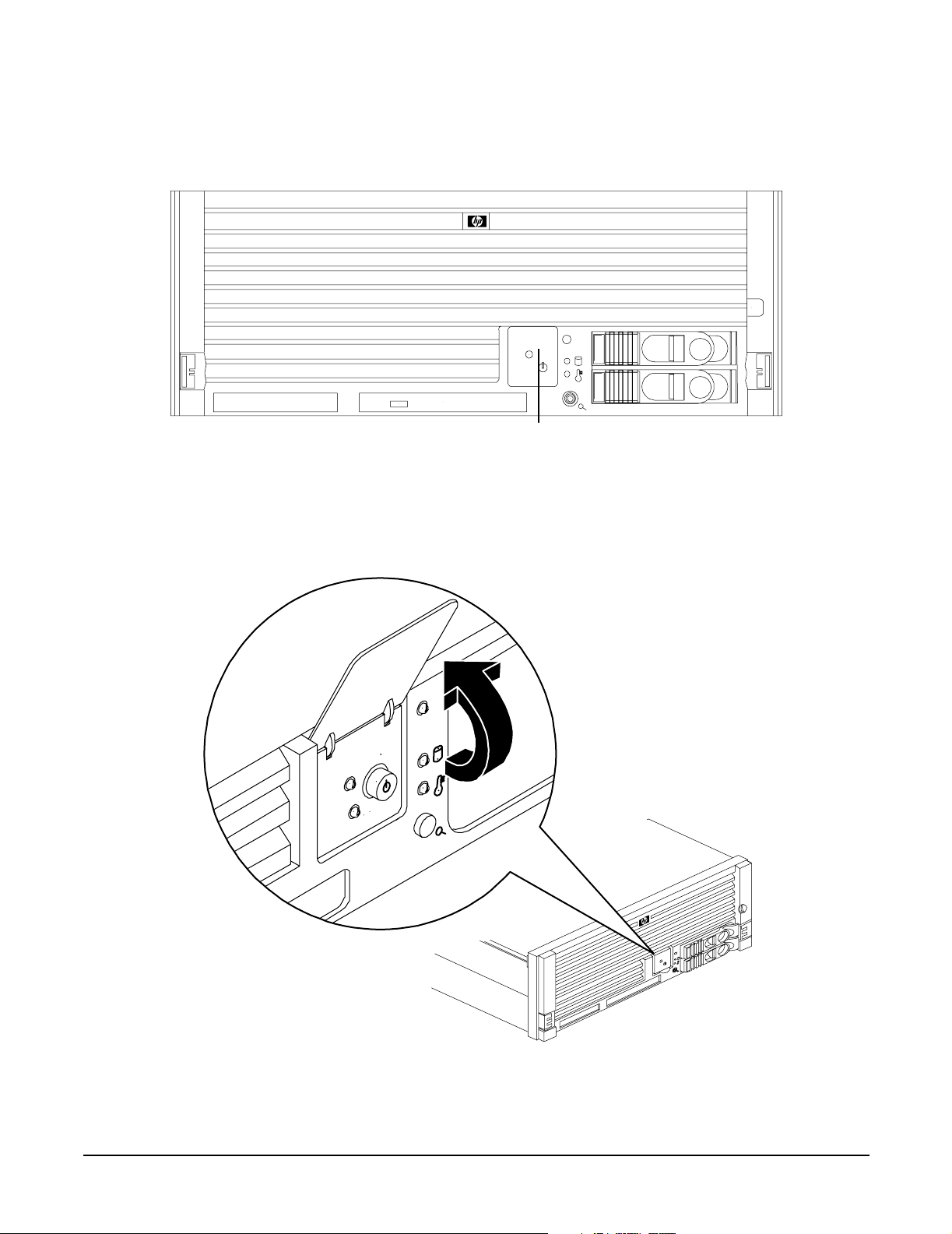
Figure 1-4 shows the control panel on the server front.
Figure 1-4 Control Panel - Front View of Server (with Bezel)
Control Panel
Overview
Controls, Ports, and LEDs
Figure 1-5 shows how to access the control panel. The front control panel access door is on the bezel.
Figure 1-5 Accessing the Control Panel
Chapter 1
25
Page 26

Overview
Controls, Ports, and LEDs
Figure 1-6 shows the control panel LEDs and buttons.
Figure 1-6 Control Panel LEDs and Buttons
Power LED
Power Button
TOC/NMI Button
Table 1-2 lists the control panel LED status and descriptions.
Table 1-2 Control Panel LED Definitions
System LED
Disk LED
Thermal LED
Locator
Button/LED
LED or
Button
System LED Running Steady Green System normal, OS up and running.
System LED Booting Flashing at 0.5 Hz Green OS booting or at BCH.
System LED Attention Flashing at 1 Hz Yellow Warning-system needs attention.
System LED Fault Flashing at 2 Hz Red Hard fault. system halted.
System LED Off Off N/A System off.
Power LED On Steady Green Power normal.
Power LED On Flashing at 1 Hz Yellow Housekeeping voltage present.
Power LED Off Off Off Power off.
Disk LED Flashing at rate of
Thermal
LED
Thermal
LED
State Flash Rate Color Description
Redundancy lost, component failure pending.
Green Disk activity.
disk activity
OK Steady Green Thermal OK.
Warning Flashing at 1 Hz Yellow Thermal warning.
Locator
Button or
LED
26
Flashing at 1 Hz Blue System locator LED can be remotely or
locally activated or deactivated. There is also
a locator button on the rear panel of the
server. Pressing either button turns both
LEDs on or off and enables or disables the
locator function.
Chapter 1
Page 27

Controls, Ports, and LEDs
Table 1-3 lists LED definitions for the switches and buttons.
Table 1-3 Switch and Button LED Definitions
Switch and Button Description
Power Button Controls the power supply (turns system power on or off) if power is available to
the power supply. (Controls both power supplies if two are installed).
If power is off but power is available to the power supplies, pressing the power
button does the following:
• From zero to five turns on the power supplies and applies power to server
circuits.
• More than five seconds then released, has no effect.
If power is on and the system is at initial system loader, pressing the power
button:
• Momentarily (less than one second) has no effect.
• More than one second, but less than five seconds—do not use. This initiates
e-buzzer functions that are not supported in the server.
Overview
• More than five seconds then released causes an immediate hard power off.
If power is on and the system is at BCH, pressing the power button does the
following:
• From zero to five sceonds has no effect.
• More than five seconds then released causes an immediate hard power off.
If power is on but the OS has been shut down, pressing the power button:
• Momentarily (less than one second) has no effect.
• More than one second, but less than five seconds—do not use. This initiates
e-buzzer functions that are not supported in the servers.
• More than five seconds then released causes an immediate hard power off.
If the OS is running, pressing the power button does the following:
• Momentarily (less than one second) has no effect.
• More than one second, but less than five seconds—do not use. This initiates
e-buzzer functions that are not supported in the servers.
• More than five seconds then released causes an immediate hard power off.
NMI Button Use a paper clip to press this button. Press the non-maskable interrupt (NMI)
button before restarting the system after a the system hangs. NMI provides crash
dump capture capability. Obtain a system hardware status dump to use in root
cause analysis and debugging. The same function is available with the CM>TC iLO
MP command.
Chapter 1
27
Page 28

Overview
Controls, Ports, and LEDs
Rear Panel
The server rear panel includes communication ports, I/O ports, ac power connectors, two power supply bays,
attention LED indicators for the hot-pluggable PCI boards, and the locator LED button. LEDs located on the
rear panel of the server signal the operational status of the following components:
• Power supplies
•iLO MP LAN
• Gigabit Ethernet card LAN
•PCI slots 3-8
Figure 1-7 shows the rear panel LEDs.
Figure 1-7 Rear Panel LEDs
Gigabit Ethernet LAN LEDs
iLO MP LAN LEDs
Locator Button/LED
Power Supply Status LEDs
Each power supply unit has three status LEDs located on the power supply rear side. The front control panel
power status LED reports a consolidated status of all power supplies.
28
6 PCI Attention LEDs
Chapter 1
Page 29

Figure 1-8 show the power supply status LEDs.
Figure 1-8 Power Supply Status LED
Overview
Controls, Ports, and LEDs
Predict Fail
LED (Amber)
Table 1-4 lists power supply status LED information.
Table 1-4 Power Supply Status LED
Pow e r LED
(Green)
Predict Fail
LED (Amber)
Fail LED
(Amber)
Power LED (Green)
Fail LED (Amber)
Status
Off Off Off No ac power is applied to all PSUs.
Off Off On No ac power is applied to this PSU only.
Blinking Off Off ac present and the standby outputs are on.
On Off Off PSU dc outputs are on and OK.
Off Off On Power supply failure.
On Blinking Off Predictive failure. The PSU is about to fail because of a
poorly performing fan.
On Off Blinking Current limit on 48 VDC output.
Chapter 1
29
Page 30

Overview
Controls, Ports, and LEDs
iLO MP LAN LEDs
NOTE There are two different iLO MP cards that were installed in this server. They have different
LEDs on them. Both of them are shown below.
One of the iLO MP LAN cards has the amber LED on the left abd the green LED on the right. It is shown in
Figure 1-9. The internal Integrity iLO MP LAN uses an RJ-45 type connector. This connector has two LEDs
(LAN link and LAN activity) that signal status and activity.
Figure 1-9 iLO MP LAN LEDs
100 M Link/Activity, Amber LED
USB Ports
Table 1-5 provides iLO MP LED status descriptions.
10 M Link/Activity, Green LED
Locator Button and LED
Table 1-5 iLO MP LED Status Descriptions
LED Condition Status
100 M amber On Linked at 100 MBs. No activity.
100 M amber Blinking Linked at 100 MBs. Activity present.
10 M green On Linked at 10 MBs. No activity.
10 M green Blinking Linked at 10 MBs. Activity present.
30
Chapter 1
Page 31

Overview
Controls, Ports, and LEDs
The other iLO MP LAN card has the green LED on the left and the amber LED on the right. Is is shown in
Figure 1-10.
Figure 1-10 iLO MP LAN LEDs
100 M Link/Activity, Green LED
USB Ports
Table 1-6 provides iLO MP LED status descriptions.
10 M Link/Activity, Amber LED
Locator Button and LED
Table 1-6 iLO MP LED Status Descriptions
LED Condition Status
100 M green On Linked at 100 MBs. No activity.
100 M green Blinking Linked at 100 MBs. Activity present.
10 M amber On Linked at 10 MBs. No activity.
10 M amber Blinking Linked at 10 MBs. Activity present.
Single-Port Gigabit Ethernet LAN Card
The single-port Gigabit Ethernet LAN card uses an RJ-45 LAN connector. This connector has four LEDs
(three LAN link and one LAN activity) that signal link speed and activity.
Figure 1-11 Single-Port GigE LAN Connector and LEDs
RJ-45 Connector
1000
100
Activity
10
Chapter 1
31
Page 32

Overview
Controls, Ports, and LEDs
Table 1-7 lists the single-port Gigabit Ethernet LAN card LED status descriptions.
Table 1-7 Single-Port GigE LAN LED Status Descriptions
LED Color Condition Status
Activity Green On Linked. No activity.
Activity Green Off No link.
Activity Green Blinking Linked. Activity present.
1000-BaseT Green On Link speed—1000 MBs.
100-BaseT Green On Link speed—100 MBs.
10-BaseT Green On Link speed—10 MBs.
Figure 1-12 and Table 1-8 shows the dual-port Gigabit Ethernet LAN card LEDs and status descriptions.
Figure 1-12 Dual-Port GigE LAN Card LEDs
Activity/Link LEDs
Flashing = Data traffic
Solid = Active link
Speed LEDs
Off = 10 Mbit/s
Green = 100 Mbit/s
Yellow = 1000 Mbit/s
PCI-X
Dual-Port
1000Base-T
Port B
RJ-45 Connectors
}
Port A
32
Chapter 1
Page 33

Table 1-8 Dual-Port GigE LAN Card LED Status Descriptions
LED Condition Status
Activity Flashing Linked, data traffic.
Activity Solid Active link.
Speed Off Link speed 10 Mbit/s.
Speed Green Link speed 100 Mbit/s.
Speed Amber Link speed 1000 Mbit/s.
Ports and Connectors
Figure 1-13 shows the ports and connectors found on the rear panel of the server.
Figure 1-13 Server Rear View
Overview
Controls, Ports, and LEDs
HBA, Ultra 3 SCSI, 68 Pin
Local Remote
Aux
3 Serial Ports
Video Port
(Disabled)
Gigabit Ethernet LAN Port
iLO MP LAN Port
USB Ports
The SCSI HBA card in slot 1 and the Gigabit Ethernet card in slot 2 are factory installed.
Chapter 1
33
Page 34

Overview
Controls, Ports, and LEDs
USB Ports
Figure 1-14 and Table 1-9 show the USB port connector and pinouts.
Figure 1-14 USB Port Connector
Table 1-9 USB Pinouts
Pin Number Signal Description
1+5 VDC
2MR
3PR
4 Ground
VGA Port
The VGA (video) port is disabled on the rp4410 and rp4440 servers.
Serial Ports
Figure 1-15 and Table 1-10 show the serial port connector and pinouts.
Figure 1-15 Serial Port Connector
Table 1-10 Serial Port Pinouts
Pin Number Signal Description
1 Data carrier detect
34
Chapter 1
Page 35

Table 1-10 Serial Port Pinouts (Continued)
Pin Number Signal Description
2Receive data
3Transmit data
4 Data term ready
5 Ground
6 Data set ready
7 Request to send
8Clear to send
9 Ring indicator
iLO MP LAN Port
Figure 1-16 and Table 1-11 show the iLO port connector and pinouts.
Overview
Controls, Ports, and LEDs
Figure 1-16 iLO MP Port
10M
Link/Activity
Amber LED
18
Table 1-11 iLO MP LAN Port Pinouts
Pin Number Signal Description
1TXP
2TXN
3RXP
4Not used
5Not used
6RXN
7Not used
100M Link/Activity
Green LED
8Not used
Chapter 1
35
Page 36

Overview
Controls, Ports, and LEDs
Gigabit Ethernet LAN Port
Figure 1-17 and Table 1-12 show the Gigabit Ethernet LAN port connector and pinouts.
Figure 1-17 Gigabit Ethernet LAN Port
Table 1-12 Gigabit Ethernet LAN Port Pinouts
Pin Number Signal Description
1RXP
2RXN
3TXP
4Not used
5Not used
6TXN
7Not used
8Not used
SCSI Port, Ultra 3, 68-Pin
Two Ultra 3, 68-pin SCSI connectors are located on the HBA located in PCI slot 1. The upper connector
supports SCSI channel A and the lower connector supports SCSI channel B.
36
Chapter 1
Page 37

Controls, Ports, and LEDs
Figure 1-18 and Table 1-13 show the SCSI port connector and pinouts.
Figure 1-18 SCSI Port, Ultra 3, 68-Pin
Table 1 -1 3 SCS I Port P i no u ts
Pin Number Signal Description Pin Number Signal Description
1 S1 (+DB 12) 35 S35 (–DB 12)
Overview
2 S2 (+DB 13) 36 S36 (–DB 13)
3 S3 (+DB 14) 37 S37 (–DB 14)
4 S4 (+DB 15) 38 S38 (–DB 15)
5 S5 (+DB P 1) 39 S39 (–DB P 1)
6 S6 (+DB 0) 40 S40 (–DB 0)
7 S7 (+DB 1) 41 S41 (–DB 1)
8 S8 (+DB 2) 42 S42 (–DB 2)
9 S9 (+DB 3) 43 S43 (–DB 3)
10 S10 (+DB 4) 44 S44 (–DB 4)
11 S11 (+DB5) 45 S45 (–DB 5)
12 S12 (+DB 6) 46 S46 (–DB 6)
13 S13 (+DB 7) 47 S47 (–DB 7)
14 S14 (+DB P) 48 S48 (–DB P)
15 S15 49 S49
16 S16 (DIFFSENS) 50 S50
17 S17 (TERMPWR) 51 S51 (TERMPWR)
18 S18 (TERMPWR) 52 S52 (TERMPWR)
19 S19 (RESERVED) 53 S53 (RESERVED)
20 S20 54 S54
Chapter 1
37
Page 38

Overview
Controls, Ports, and LEDs
Table 1-13 SCSI Port Pinouts (Continued)
Pin Number Signal Description Pin Number Signal Description
21 S21 (+ATN) 55 S55 (–ATN)
22 S22 56 S56
23 S23 (+BSY) 57 S57 (–BSY)
24 S24 (+ACK) 58 S58 (–ACK)
25 S25 (+RST) 59 S59 (–RST)
26 S26 (+MSG) 60 S60 (–MSG)
27 S27 (+SEL) 61 S61 (–SEL)
28 S28 (+C/D) 62 S62 (–C/D)
29 S29 (+REQ) 63 S63 (–REQ)
30 S30 (+I/O) 64 S64 (–I/O)
31 S31 (+DB 8) 65 S65 (–DB 8)
32 S32 (+DB 9) 66 S66 (–DB 9)
33 S33 (DB 10) 67 S67 (–DB 10)
34 S34 (DB 11) 68 S68 (–DB 11)
38
Chapter 1
Page 39

Controls, Ports, and LEDs
Additional Controls and LEDs
Storage devices have additional LEDs showing their status.
Hot-Pluggable Disk Drive LEDs
Figure 1-19 and Table 1-14 show the hot-pluggable disk drive LED indicators and definitions.
Figure 1-19 Hot-Pluggable Disk Drive LED Indicators
Status LED
Activity LED
Overview
Table 1-14 Hot-Pluggable Disk Drive LED Definitions
LED State Description
Activity LED Flashing green Drive is active.
Status LED Solid green Drive is operating (power applied).
DVD Drives
The server is delivered with one DVD drive. DVD-R and DVD-RW drives are optional. Each of these devices
has one activity LED.
Figure 1-20 and Table 1-15 show the DVD drive and DVD drive LED definitions.
Figure 1-20 DVD Drive
Eject Button
Activity LED
Emergency Eject
Table 1-15 DVD Drive LED Definitions
LED State Description
Activity LED Flashing green Drive is active.
Chapter 1
39
Page 40

Overview
Controls, Ports, and LEDs
QuickFind Diagnostic Panel
The QuickFind diagnostic panel has 27 single color LEDs and one multi-color LED for temperature. The
LEDs are normally off. The appropriate LED is turned on when an error is detected or a replacement part is
required.
Accessing the QuickFind Diagnostic Panel
You can access the QuickFind diagnostic panel by removing the top cover. Use the QuickFind diagnostic panel
as an aid in troubleshooting. (See “QuickFind Diagnostic Panel LEDs” on page 163.)
Figure 1-21 shows the QuickFind diagnostic panel.
Figure 1-21 QuickFind Diagnostic Panel
Processor
Subsystem
I/O VRM
CPU VRM
Fan
Memory 0
Memory 1
Memory 2
Memory 3
Memory 4
Memory 5
Memory 6
Memory 7
Power Supply
Memory Config Error
Processor Config Error
Missing Component
System Temperature
Check Event Log
I/O Baseboard LED Indicators
You can find LEDs, sensors, reset, and attention buttons on the I/O baseboard.
40
Chapter 1
Page 41

Controls, Ports, and LEDs
Figure 1-22 shows the I/O baseboard LEDs, buttons, and sensors and Table 1-16 lists their definitions.
Figure 1-22 I/O Baseboard LEDs, Buttons, and Sensors
Battery
3.3 VSB
Power
LED
BMC
Reset
Button
Overview
5V VRM
LED
iLO MP Soft
Reset
Button
iLO MP
Self-Test
LED
iLO MP Heartbeat LED
BMC Heartbeat LED
3.3V VRM LED
Locator Button/LED
12V VRM LED
PCI Attention
LED
PCI Attention
Button
PCI Power LED
PCI Attention LED
Chapter 1
41
Page 42

Overview
Powering the Server On and Off
Table 1-16 I/O Baseboard LEDs, Buttons, and Sensors
LED/Button Color Status Condition
12V VRM Power LED Green On 12V VRM is functioning.
5V VRM Power LED Green On 5V VRM is functioning.
3.3V VRM Power LED Green On 3.3V VRM is functioning.
iLO MP Heartbeat Green Blinking The iLO MP is functioning correctly.
iLO MP Self Test LED Amber On
Off
BMC Heartbeat Green Blinking The baseboard management controller (BMC) is
3.3 VSB Power LED Green On Standby power is available.
iLO MP Soft Reset
Button
N/A Press Resets the iLO MP values.
The iLO MP is executing the internal self test.
The iLO MP passed the internal self test.
functioning correctly.
Powering the Server On and Off
This section provides information on how to power off and power on the server.
Power States
The server has three power states:
•Standby power
•Full power
•Off
Plug the power cord into the appropriate receptacle on the rear of the server to achieve the standby power
state; the front panel power button is not turned on. Full power occurs when the power cord is plugged into
the appropriate receptacle and either the power is activated through the iLO MP PC command, or the power
button is activated. In the off state, the power cords are not plugged in.
Table 1-17 lists the server power states.
Table 1-17 Power States
Power Cable
Power States
Standby power Yes No Yes No
42
Plugged Into
Receptacle?
Power Activated through the
iLO MP PC Command; or
Front Panel Power Button
Activated?
Standby
DC Voltage
Applied?
DC Voltage
Applied?
Chapter 1
Page 43

Table 1-17 Power States (Continued)
Overview
Powering the Server On and Off
Power Cable
Power States
Full power Yes Yes Yes Yes
Off No No No No
NOTE If the power restore feature is set to Always On through the iLO MP PR command, the server
automatically powers on to the full power state.
Plugged Into
Receptacle?
Power Activated through the
iLO MP PC Command; or
Front Panel Power Button
Activated?
Standby
DC Voltage
Applied?
DC Voltage
Applied?
Powering On the Server
Power on the server to full power using the following methods if the server is in the standby power state:
•iLO MP PC command
• Power button
Powering On the Server Using the iLO MP
NOTE If the power restore feature is set to Always On through the iLO MP PR command, the server
automatically powers on to the full power state.
To power on the server using the iLO MP, follow these steps:
Step 1. Plug all power cables into the receptacles on the rear panel of the server.
Step 2. Initiate a console session, and access the
Step 3. Enter CM to enable command mode.
Step 4. Enter PC to use the remote power control command.
Step 5. Enter ON to power on the server, and enter YES when prompted to confirm the action.
Step 6. Start the operating system.
Powering On the Server Manually
NOTE If the power restore feature is set to Always On through the iLO MP PR command, the server
automatically powers on to the full power state.
To manually power on the server, follow these steps:
MP Main Menu.
Step 1. Plug all power cables into the receptacles on the rear panel of the server.
Chapter 1
43
Page 44

Overview
Powering the Server On and Off
Step 2. Press the power button to start the server.
Step 3. Start the operating system.
Powering Off the Server
Power off the server using the following methods if the server is in the standby or full power state:
•iLO MP PC command
• Power button
Powering Off the Server Using the iLO MP
To power off the server using the iLO MP, follow these steps:
Step 1. Gracefully shut down the operating system.
Step 2. Initiate a console session, and access the
Step 3. Enter CM to enable command mode.
Step 4. Enter PC to use the remote power control command.
Step 5. Enter OFF to power off the server, and enter YES when prompted to confirm the action.
IMPORTANT The main dc voltage is now removed from the system; however, ac voltage for
standby power is still present in the server.
Step 6. Unplug all power cables from the receptacles on the rear panel of the server.
Powering Off the Server Manually
To manually power off the server, follow these steps:
Step 1. Gracefully shut down the operating system.
Step 2. Press the power button to power off the server.
IMPORTANT The main dc voltage is now removed from the system; however, ac voltage for
standby power is still present in the server.
Step 3. Unplug all power cables from the receptacles on the rear panel of the server.
MP Main Menu.
44
Chapter 1
Page 45

2 System Specifications
This chapter provides information on the basic system configuration, physical specifications, and
requirements for the HP 9000 rp4410 or rp4440 server.
This chapter addresses the following topics:
• “System Configuration” on page 45
• “Dimensions and Values” on page 46
• “Grounding” on page 46
• “Electrical Specifications” on page 47
• “Environmental Specifications” on page 50
System Configuration
Table 2-1 lists the minimum and maximum configuration options for the HP 9000 rp4410 and rp4440 servers.
Table 2-1 Minimum and Maximum Server Configurations
Component rp4410 rp4440
Microprocessors One or two dual-core processor modules,
each containing two PA RISC
800 MHz/1.5 MB cache or
1 GHz/1.5 MB cache. The CPUs are
available with 32 MB or 64 MB L2
cache. A single CPU or all installed
CPUs can be activated.
Memory Supports up to 16 Double Data Rate
(DDR) registered ECC memory, in
PC2100 DIMMs. Up to 32 DDR DIMMs
can be optionally used. Maximum
memory is 128 GB. Supported DDR
DIMM sizes: 256 MB and 512 MB, 1 GB,
2 GB, and 4 GB.
HDDs 2-36 GB, 15K RPM Ultra320 SCSI
hot-plug disks or
2-73 GB, 15K RPM Ultra320 SCSI
hot-plug disks or
2-146 GB, 10K RPM Ultra320 SCSI
hot-plug disks.
SCSI Integrated Ultra-3 SCSI dual channel
controller; 80 Mb/s transfer rate with
two external 68-pin connectors.
Up to four dual-core processor modules,
each containing two PA RISC
800 MHz/1.5 MB cache or
1 GHz/1.5 MB cache. The CPUs are
available with 32 MB or 64 MB L2 cache.
All installed CPUs (2, 4, 6, or 8) are
activated.
Supports up to 16 Double Data Rate
(DDR) registered ECC memory, in
PC2100 DIMMs. Up to 32 DDR DIMMs
can be optionally used. Maximum
memory is 128 GB. Supported DDR
DIMM sizes: 256 MB, 512 MB, 1 GB, 2
GB, and 4 GB.
2-36 GB, 15K RPM Ultra320 SCSI
hot-plug disks or
2-73 GB, 15K RPM Ultra320 SCSI
hot-plug disks or
2-146 GB, 10K RPM Ultra320 SCSI
hot-plug disks.
Integrated Ultra-3 SCSI dual channel
controller; 80 Mb/s transfer rate with
two external 68-pin connectors.
LAN PCI GB Fast Ethernet controller. PCI GB Fast Ethernet controller.
Chapter 2
45
Page 46

System Specifications
Dimensions and Values
Table 2-1 Minimum and Maximum Server Configurations (Continued)
Component rp4410 rp4440
PCI Slots Two dedicated for LAN and SCSI; four
64-bit PCI-X slots, 66 MHz, 3.3V slots;
and two 64-bit PCI-X slots, 133 MHz,
3.3V slots.
Core I/O Three serial ports, two USB ports,
integrated RJ-45 LAN.
DVD DVD-R/CD drive, IDE interface, 48x
speed.
External storage Two external SCSI ports. Two external SCSI ports.
Power supply One power supply standard. A second
power supply (optional) for 1+1
configuration.
Two dedicated for LAN and SCSI; four
64-bit PCI-X slots, 66 MHz, 3.3V slots;
and two 64-bit PCI-X slots, 133 MHz,
3.3V slots.
Three serial ports, two USB ports,
integrated RJ-45 LAN.
DVD-R/CD drive, IDE interface, 48x
speed.
One power supply standard. A second
power supply (optional) for 1+1
configuration.
Dimensions and Values
Table 2-2 provides dimensions and their values of HP 9000 rp4410 and rp4440 servers.
Table 2-2 Server Dimensions and Values
Dimension Value
Height 6.8 in (17.3 cm)
Width 19 in (48.2 cm)
Depth 27.2 in (69.0 cm)
Weight Unloaded 88 lbs (40 kg)
Fully loaded 100 lbs (45.4 kg)
Height 6.8 in (17.3 cm)
Grounding
The site building must provide a safety ground or protective earth for each ac service entrance to all cabinets.
Install a protective earthing (PE) conductor that is identical in size, insulation material, and thickness to the
branch-circuit supply conductors. The PE conductor must be green with yellow stripes. The earthing
conductor is to be connected from the unit to the building installation earth or, if supplied by a separately
derived system, at the supply transformer or motor-generator set grounding point.
46
Chapter 2
Page 47

System Specifications
Electrical Specifications
Electrical Specifications
This section provides electrical specifications for the server.
AC Power Cords
Table 2-3 lists the power cables available for use with the HP 9000 rp4410 and rp4440 servers.
Table 2-3 Power Cords
Part Number Description Country
8120-5341 Power Cord C15/S Africa 2.5m black CA ASSY 917 South Africa
8120-1351 Power Cord C13/BS-1363 2.3m black CA ASSY 900 United Kingdom
Hong Kong
Singapore
8120-1369 Power Cord C13/AS-3112 2.0m gray CA ASSY 901 Australia
8120-1689 Power Cord C13/CEE 7 2.0m black CA ASSY 902 Europe
8120-2104 Power Cord C13/SEV 12 2.0m black CA ASSY 906 Switzerland
8120-6814 Power Cord OPT-912 3-COND 2.25-M-LG 912 Denmark
8120-0698 Power Cord C13/6-15P 0.0m black CA ASSY 904 / 918 North America (250#V)
Japan
8120-6800 Power Cord OPT-919 3-COND 2.3-M-LG 919 Israel
8120-8390 Power Cord C15/CEI 23-16 2.5m black CA ASSY 920 Argentina
8120-8389 Power Cord C15/CEI 23-16 2.5m black CA ASSY 921 Chile
8120-8376 Power Cord C13/GB-1002 2.236m gray CA ASSY 922 China
8121-0668 Power Cord OPT-927 3-COND 2.3-M-LG FLNT 927 South America
8120-6514 C13/C14 Jumper cord All
Circuit Breaker
The marked electrical size for the server is eight amps. The recommended circuit breaker size is 12 amps per
line cord (2 maximum) for North America. For countries outside North America, consult the local electrical
authority that has jurisdiction for the recommended circuit breaker size.
System Power Specifications
The following tables provide information to help determine the amount of ac power needed for your computer
room.
Chapter 2
47
Page 48

System Specifications
Electrical Specifications
Table 2-4 lists the ac power requirements for the server.
Table 2-4 System Power Specifications
Specification Value
Nominal input voltage 200 – 240 VAC
Minimum operating voltage 180 VAC
Maximum operating voltage 264 VAC
Frequency range (minimum –
maximum)
Number of phases 1
Maximum input current 8 A RMS
Maximum inrush current
(maximum configuration)
Dropout carry through time at
minimum line voltage
Power factor correction >0.95 at all loads of 90% – 100% of supply rating
Ground leakage current <1.1 mA per line cord
50 – 60 Hz
rp4410
100 A (peak), 55 A (average) 0 msec – 1 msec
55 A (peak), 33 A (average) 1 msec – 2 msec
5 A (peak), 22 A (average) 2 msec – 10 sec
25 A (peak), 15 A (average) 10 msec – 150 msec
rp4440
100 A (peak), 55 A (average) 0 msec – 1 msec
55 A (peak), 33 A (average) 1 msec – 2 msec
5 A (peak), 22 A (average) 2 msec – 10 sec
25 A (peak), 15 A (average) 10 msec – 150 msec
20 ms
>0.75 at all loads of 50% – 90% of supply rating
48
Chapter 2
Page 49

System Specifications
Electrical Specifications
Table 2-5 list maximum and typical power requirements for the HP 9000 rp4410 and rp4440 servers.
Table 2-5 System Power Requirements
Power Required (50-60 Hz) Watts VA Comments
Maximum configuration
Typical configuration
b
a
1368 1440 Maximum theoretical
1065 1125 Typical
a. Maximum power is the sum of the worst case power consumption values of every subsystem in the
HP 9000 rp4410 or rp4440 server. Use these values to calculate the worst case power consumption
for your facility installation.
b. Typical power consumption values were measured while running power intensive applications.
These values are generally lower than maximum power numbers because all the subsystems in the
server rarely draw maximum power simultaneously and for long durations.
Power and Cooling
Table 2-6 lists power and cooling values associated with servers which contain the listed components. These
power and cooling values are considered typical and not maximum for the configurations shown.
Table 2-6 lists the typical configuration power values for HP 9000 rp4410 and rp4440 servers.
Table 2-6 Typical Configuration Power Values
CPU
Qty
Memory
Gigabytes
11 GB
PCI Cards
(assuming
DVDs
10W each)
0 0 1 2 2 410 1399.74
Hard
Disk
Drives
Core
I/O
Bulk
Power
Supplies
Typical
Pow e r
(Watts)
Typical
Cooling
(BTU/Hr)
(4 DIMMs
256 MB each)
2
32 GB
a
0 0 1 1 1 540 1843.56
(32 DIMMs
1 GB each)
2
32 GB
b
a
6 1 2 2 2 700 2389.80
(32 DIMMs
1 GB each)
4
32 GB
b
a
0 1 2 2 2 895 3055.53
(32 DIMMs
1 GB each)
4
32 GB
b
a
6 1 2 2 2 975 3328.65
(32 DIMMs
1 GB each)
b
Chapter 2
49
Page 50

System Specifications
Environmental Specifications
Table 2-6 Typical Configuration Power Values (Continued)
CPU
Qty
4
4
a. The maximum memory capacity is 128 GB.
b. These memory configurations require the optional 32-DIMM slot memory extender board. The
Memory
Gigabytes
a
32 GB
(8 DIMMs
4 GB each)
128 GB
(32 DIMMs
4 GB each)
standard memory extender board has 16-DIMM slots.
a
PCI Cards
(assuming
10W each)
0 1 2 2 2 915 3121.98
6 1 2 2 2 3600 12283.2
b
DVDs
Hard
Disk
Drives
Core
I/O
Bulk
Power
Supplies
Typical
Pow e r
(Watts)
Typical
Cooling
(BTU/Hr)
Environmental Specifications
This section provides the temperature and humidity requirements, noise emission, and air flow specifications
for the server.
Operating Environment
The system is designed to run continuously and meet reliability goals in an ambient temperature of 5°C to
35°C (+40°F to +95°F) at sea level. The maximum allowable temperature is de-rated 1°C per 1,000 feet of
elevation above 5,000 feet above sea level up to 30°C at 10,000 feet. For optimum reliability and performance,
the recommended operating range is 20°C to 25°C and 40% – 55% relative humidity.
Ambient intake air temperature is often different from ambient room temperature; you should measure the
operating temperature and humidity directly in front of the cabinet cooling air intakes rather than just
checking ambient room conditions.
Environmental Temperature Sensor
The server includes internal sensors that monitor input air temperature and server operating temperatures.
The ambient air temperature is measured using a sensor placed on the system I/O board. Data from the
sensor is used to control the fan speed and to initiate system overtemperature shutdown.
Nonoperating Environment
The system is designed to withstand ambient temperatures between –40°C to 70°C under nonoperating
conditions.
50
Chapter 2
Page 51

System Specifications
Environmental Specifications
Cooling
This section provides information on the cooling systems in the server.
CPU and Memory Cooling
The server incorporates front to back airflow across the processor and memory extender boards and through
the HDD backplane. Two 127 mm dual fan assemblies, mounted vertically in the center of the chassis, pull air
through the processor and memory section and push air through the PCI section.
Each processor and memory dedicated dual fan assembly is controlled by smart fan control circuits embedded
in the system I/O board. The smart fan control circuit receives fan control input from the system fan
controller in the I/O board, and returns fan status information to the system fan controller. The smart fan
circuit controls the power and the pulse-width-modulated control signal to the fan and monitors the speed
indicator back from each of the fans. The fan status LED is driven by the smart fan circuit. The fan status
LED is located on the diagnostic board inside the system.
Bulk Power Supply Cooling
Cooling for the bulk power supplies is provided by one 120 mm dual fan assembly and one externally mounted
60 mm power supply fan. Air is pushed into both power supply bays by the 120 mm fan assembly and
exhausted out the rear by the 60 mm fan (one per power supply).
Air flows out of the rear of the chassis with minimal leakage into the cell airflow plenum.
NOTE A power supply filler is required in the unused power supply slot to maintain proper airflow
throughout the system.
PCI and Mass Storage Section Cooling
Two dual fan assemblies located at the center of the chassis provide airflow for all the PCI slots. Airflow is
over the processor and memory extender boards and into the PCI section. The fans are controlled by the
system temperature and run at the speed necessary to maintain proper internal temperature throughout the
chassis.
The air is pulled through openings in the front cover and the mass storage devices and pushed through the
PCI card cage.
Perforation is provided between and above the PCI card cage to enable proper exhaust ventilation to maintain
the required temperature rating of the PCI cards.
CAUTION For maximum cooling effects, ensure that the chassis ventilation holes are not blocked or
covered after installation.
Chapter 2
51
Page 52

System Specifications
Environmental Specifications
Figure 2-1 shows the airflow through the server.
Figure 2-1 Airflow Through HP 9000 rp4410 and rp4440 Servers
Acoustic Noise Specification
The acoustic noise specification for the HP 9000 rp4410 or rp4440 server is 53 db LpA (sound pressure level at
bystander position in a dedicated computer room environment temperature of <25°C).
52
Chapter 2
Page 53

System Specifications
Physical and Environmental Specifications
Physical and Environmental Specifications
Table 2-7 provides temperature and airflow information for minimum, typical, and maximum configurations
for the HP 9000 rp4410 and rp4440servers. It also lists the server and rack weights and dimensions.
Table 2-7 Physical and Environmental Specifications
Condition
Typical
Heat
Release
180-264
VAC
Airflow, Nominal
Airflow, at
Maximum
Ambient
degrees C
Wei ght
a
Server
Alone
Rack
Pede-
stal
Overall Server
(W x D x H)
Rack
Pede-
stal
Min.
Config.
Max.
Config.
Typical
Config.
ASHRAE
Class 1
410 Watts
1368 Watts
1065 Watts
175
CFM
297
3
m
/hr
Airflow cooling scheme (front to
rear)
250
CFM
425
m3/hr
Min./
Config.
Max.
Config.
Typical
Config.
88 lbs
(40 kg)
One CPU, one power supply, 1 GB DIMM, zero
DVD, one HDD, zero PCI cards, one core I/O.
Four CPUs, two power supplies, 128 GB DIMM,
one DVD, two HDD, six PCI cards, two core I/O.
Two CPUs, two power supplies, 16 GM DIMM,
one DVD, two HDD, two PCI cards, one core I/O.
a. Derate maximum dry bulb temperature 1 degree per 300 meters above 900 meters.
100 lbs
(45.4 kg)
115 lbs
(53 kg)
W: 19 in
(48.2 cm)
D: 27.2 in
(69.0 cm)
H: 6.8 in
(17.3 cm)
W: 10.3 in
(26.1 cm)
D: 27.4 in
(69.5 cm)
H: 20.9 in
(53.0 cm)
Chapter 2
53
Page 54

System Specifications
Physical and Environmental Specifications
54
Chapter 2
Page 55

3 Installing the System
This chapter provides information on how to install the system.
This chapter addresses the following topics:
• “Introduction” on page 55
• “Unpacking and Inspecting the Server” on page 62
• “Installing Additional Components” on page 63
• “Installing the Server Into a Rack, Non-HP rack, or Pedestal” on page 115
• “Connecting the Cables” on page 116
• “Console Setup” on page 118
• “Accessing the Host Console” on page 127
• “Powering the Server ON and Off” on page 131
• “Booting the Operating System” on page 134
• “Troubleshooting” on page 136
Introduction
The HP 9000 rp4410 and rp4440 servers are 1P/1C, 1P/2C, 2P/2C, 3P/2C, or 4P/2C servers based on the
PA-RISC processor family architecture. The server accommodates up to 32 DIMMs and internal peripherals
including hard disks and a DVD drive. Its high availability features include hot-swappable fans,
hot-swappable power supplies, hot-pluggable disk drives, and hot-pluggable PCI-X cards. The supported
operating system is HP-UX 11i v1 (and higher HP-UX versions that support PA-RISC systems).
Chapter 3
55
Page 56

Installing the System
Server Views
Server Views
Figure 3-1, Figure 3-2, and Figure 3-3 show the top, front, and rear views of the HP 9000 rp4410 and rp4440
servers.
Figure 3-1 HP 9000 rp4410 and rp4440 Servers (Top View)
56
Chapter 3
Page 57

Installing the System
Detailed Server Description
Figure 3-2 HP 9000 rp4410 and rp4440 Servers with Bezel Removed (Front View)
Figure 3-3 HP 9000 rp4410 and rp4440 Servers (Rear View)
Detailed Server Description
The following sections list information on the main subsystems within the HP 9000 rp4410 and rp4440
servers.
I/O Subsystem
The following is supported on the HP 9000 rp4410 and rp4440 servers:
• PCI-X slots available - 8.
— Two dedicated PCI slots: Slot 1 is for SCSI; slot 2 is for LAN.
— Four hot-pluggable PCI-X 66 MHz 64-bit 3.3V 25W slots with shared busses and I/O. Slots 3 and 4
share capabilities and slots 5 and 6 share capabilities.
— Two hot-pluggable PCI-X 133 MHz 64-bit 3.3V 15W slots dedicated for core I/O.
Chapter 3
57
Page 58

Installing the System
Detailed Server Description
• I/O bandwidth - 4 GBs.
• Pinnacle FXe PCI video card.
• PCI Gigabit, Fast Ethernet Controller with Wake-on-LAN enabled/disabled with BIOS setup.
Internal Core I/O
The following is supported on the HP 9000 rp4410 and rp4440 servers:
• Dual channel SCSI U320 or U160 (PA8800 only) interface or RAID, two internal 68-pin connectors, two
68-pin external connectors.
• SCSI backplane configured as either one or two channels.
• One internal Integrated Drive Electronics (IDE) connector for a slimline optical device (CD and DVD).
• No floppy connector.
• Optional dual channel U320 RAID controller, two internal 68-pin connectors, two 68-pin external
connectors (replaces SCSI interface).
External Core I/O
The following is supported on the HP 9000 rp4410 and rp4440 servers:
• Three external serial ports.
• Two external USB ports.
• Two SCSI U320 or U160 68-pin connectors (U160 for PA8800 only).
• One or two 10/100/1000Base-T ethernet LAN connectors for copper cable.
• Two USB 2.0 ports.
• Three DB-9 ports (console, UPS, and modem).
• Optional dual channel U320 RAID controller, two 68-pin external connectors (replaces SCSI interface).
Processors
The following is supported on the HP 9000 rp4410 and rp4440 servers:
• 800 MHz/1.5 GB cache or 1 GHz/1.5 GB cache per CPU.
• Both processors are available with 32 MB or 64 MB L2 cache per dual processor module.
• HP 9000 rp4410 server can have one processor or both processors of a single dual processor module
enabled, or two processors enabled in each of two dual processor modules.
• HP 9000 rp4440 server can be 1P/2C, 2P/2C, 3P/2C, or 4P/2C.
Memory
The following is supported on the HP 9000 rp4410 and rp4440 servers:
• 16 DIMM slots on standard memory extender board.
• 32 DIMM slots on optional memory extender board.
• Maximum memory size of 128 GB (4 GB DIMMs on 32-slot memory extender board).
• Supports up to 32 Double Data Rate (DDR) registered ECC memory, in PC2100 DIMMs.
58
Chapter 3
Page 59

Detailed Server Description
• Supported DDR DIMM sizes:
— 128 MB, 256 MB, 512 MB, 1 GB, 2 GB, and 4 GB
— Standard 184 pins 2.5V DDR266, CL2, registered, ECC
• 133 MHz memory bus frequency, 266 MTransfers/s data, 8.5 GB/s peak data bandwidth.
• DIMMs loaded by quads enable interleaved mode and chip spare.
• Requires that DIMMs within each group of four (quad) be identical.
Cooling
Six cooling fans with N+1 redundancy.
Power Supply Unit
The following is supported on the HP 9000 rp4410 and rp4440 servers:
• One 1200 W hot-swappable power supply.
• Optional second 1200 W hot-swappable power supply for N+1 redundancy.
Installing the System
Front Display Panel, DVD, and Diagnostic Panel
The following is supported on the HP 9000 rp4410 and rp4440 servers:
• Front panel that provides the controls and indicators commonly used for operation.
• DVD+RW drive (with CD-write capability); IDE interface; 48x speed.
• Optional slimline DVD drive.
• Power button and LED indicators for system status.
• LED-based diagnostic panel.
Mass Storage
The following is supported on the HP 9000 rp4410 and rp4440 servers:
• Up to two SCSI hot-pluggable hard disk drives.
• Integrated Ultra-3 SCSI dual channel controller; 80 MB/s transfer rate with two 68-pin connectors. The
SCSI backplane is configured as either one or two channels.
• Maximum internal storage of two 73 MB, 15K drives.
• Optional integrated HP RAID controller.
Firmware
Firmware consists of many individually linked binary images that are bound together by a single framework
at run time. Internally, the firmware employs a software database called a device tree to represent the
structure of the hardware platform and to provide a means of associating software elements with hardware
functionality.
Chapter 3
59
Page 60

Installing the System
Safety Information
The firmware incorporates the Boot Console Handler (BCH), which provides an interface between the
operating system and the platform firmware. BCH uses data tables that contain platform-related
information, and boot and run-time service calls available to the operating system and its loader to provide a
standard environment for booting.
The firmware supports the HP-UX 11i version 1 (and higher HP-UX versions that support PA-RISC systems)
operating system through the HP 9000 processor family standards and extensions, and has no operating
system-specific functionality included. The operating system is presented with the same interface to system
firmware, and all features are available to the operating system.
Event IDs for Errors and Events
The server firmware generates event IDs similar to chassis codes for errors, events, and forward progress to
the Integrity Integrated Light-Out Management Processor (iLO MP) through common shared memory. The
Integrity iLO MP interprets and stores event IDs. Reviewing these events helps you diagnose and
troubleshoot problems with the server.
Dimensions and Values
Table 3-1 lists the dimensions and their values of the HP 9000 rp4410 and rp4440 servers.
Table 3-1 Server Dimensions and Values
Dimension Value
Height 6.8 in (17.3 cm)
Width 19 in (48.2 cm)
Depth 27.2 in (69.0 cm)
Weight Unloaded 88 lb (40 kg)
Fully loaded 100 lb (45.4 kg)
Safety Information
Use care to prevent injury and equipment damage when performing removal and replacement procedures.
Voltages might be present within the server. Many assemblies are sensitive to damage by electrostatic
discharge.
Follow the safety conventions listed below to ensure safe handling of components, to prevent injury, and to
prevent damage to the server:
• When removing or installing any server component, follow the instructions provided in this guide.
• If installing a hot-swappable or hot-pluggable component when power is applied (fans are running),
reinstall the server cover immediately to prevent overheating.
• If installing a hot-pluggable component, complete the required software intervention before removing the
component.
• If installing an assembly that is neither hot-swappable nor hot-pluggable, disconnect the power cable
from the external server power receptacle before proceeding.
60
Chapter 3
Page 61

Installing the System
Installation Sequence and Checklist
WARNING Ensure that the system is powered off and all power sources are disconnected from
the server before removing or installing server hardware unless you are removing or
installing a hot-swappable or hot-pluggable component.
Voltages are present at various locations within the server whenever a dc power
source is connected. This voltage is present even when the main power switch is
turned off.
Failure to observe this warning can result in personal injury or damage to
equipment.
• Do not wear loose clothing that can snag or catch on the server or on other items.
• Do not wear clothing subject to static charge build up, such as wool or synthetic materials.
• If installing an internal assembly, wear an antistatic wrist strap and use a grounding mat, such as those
included in the Electrically Conductive Field Service Grounding Kit (HP 9300-1609).
• Handle accessory boards and components by the edges only. Do not touch any metal-edge connectors or
any electrical components on accessory boards.
Installation Sequence and Checklist
Follow the steps in Table 3-2 sequentially to ensure successful installation of the server.
Table 3-2 Installation Sequence Checklist
Step Description Completed
1 Unpack and inspect the server shipping container. Inventory the contents using
the packing slip.
2 Install additional components shipped with the server.
3 Install the server into a rack or pedestal mount.
4 Connect cables to the server.
4a Connect dc input power cable.
4b 4Connect LAN core I/O cable.
5 Set up the console.
6 Power on the server.
7 Access the console.
8 Boot the operating system.
9 Verify the server configuration.
Chapter 3
61
Page 62

Installing the System
Unpacking and Inspecting the Server
Unpacking and Inspecting the Server
This section describes procedures you perform before installation. Ensure that you have adequately prepared
your environment for the new server, received the components that you ordered, and verified that the server
and its containers are in good condition after shipment.
Verifying Site Preparation
Verifying site preparation is essential for a successful server installation and includes the following tasks.
Step 1. Gather LAN information and determine the two separate IP addresses for the Integrity iLO MP
LAN and the system LAN.
Step 2. Establish a method to connect to the server console.
Step 3. Verify electrical requirements and ensure that grounding specifications and power requirements
are met.
Step 4. Validate server physical space requirements.
Step 5. Confirm environmental requirements.
Inspecting the Shipping Containers for Damage
HP shipping containers protect their contents under normal shipping conditions. After the equipment arrives,
carefully inspect each carton for signs of shipping damage. Shipping damage constitutes moderate to severe
damage, such as punctures in the corrugated carton, crushed boxes, or large dents. Normal wear or slight
damage to the carton is not considered shipping damage. If you find shipping damage to the carton, contact
your HP customer service representative immediately.
Unpacking the Server
To unpack a nonracked server, follow these steps.
NOTE HP recommends the use of a lifter, such as a RonI Company model 17000 SP 400 lifting device,
when moving a nonracked system.
Step 1. Use the instructions printed on the outside top flap of the carton; remove the banding and the outer
carton from the server pallet.
Step 2. Remove all inner accessory cartons and the top foam cushions, leaving only the server.
IMPORTANT Inspect each carton for shipping damage as you unpack the server.
Checking the Inventory
The sales order packing slip lists all of the equipment shipped from HP. Use this packing slip to verify that all
of the equipment has arrived.
62
Chapter 3
Page 63

Installing the System
Installing Additional Components
NOTE To identify each item by part number, see the sales order packing slip.
Returning Damaged Equipment
If the equipment is damaged, contact your HP customer service representative immediately. The service
representative initiates appropriate action through the transport carrier or the factory and assists you in
returning the equipment.
Unloading the Server with a Lifter
WARNING Use caution when using a lifter. Because of the weight of the server, you must center
the server on the lifter forks before lifting it off the pallet to avoid injury.
To unload the server from the pallet using a lifter, follow these steps:
Step 1. Unpack the server. See “Unpacking the Server” on page 62.
Step 2. Unroll the bottom corrugated tray corresponding to the side on which the lifter will be placed, and
slide the server as close to that edge of the pallet as possible.
Step 3. Break off any foam packaging that can prevent the lifter from being fully inserted under the server.
IMPORTANT Do not remove the foam packaging from the corners of the server. This foam is
required to elevate the server and enable the forks of the lifter to be placed under the
server.
Step 4. Insert the lifter forks under the server.
Step 5. Carefully roll the lifter forward until it is fully positioned against the side of the server.
Step 6. Slowly raise the server off the pallet until it clears the pallet cushions.
Step 7. Carefully roll the lifter and server away from the pallet. Do not raise the server any higher than
necessary when moving it over to the rack.
Installing Additional Components
This section describes how to install server components that are not installed before delivery.
Service Tools Required
Service of this product can require one or more of the following tools:
• Electrically Conductive Field Service Kit (HP part number 9300-1155)
• 1/4 inch flat blade screwdriver
Chapter 3
63
Page 64

Installing the System
Installing Additional Components
• ACX-15 Torx screwdriver
• Special processor tool kit (HP part number 5069-5441)
Accessing a Rack-Mounted Server
The HP 9000 rp4410 and rp4440 servers are designed to be rack mounted. The following procedure explains
how to gain access to a server that is mounted in an approved rack.
WARNING Ensure that all antitip features are employed before extending the server (front and
rear antitip feet installed; adequate ballast properly placed, and so on).
Extend the Server from the Rack
NOTE Ensure that there is enough area (approximately 1.5 meters [4.5 ft]) to fully extend the server
out the front and work on it.
To extend the server from the rack, follow these steps:
Step 1. Remove the 25-mm Torx screws that fasten the server to the rack.
Step 2. Flip out the two pull handles at either end of the front bezel and slowly pull the unit forward by the
handles. The server is fully extended when the rail clips are locked in place. After the server is fully
extended, the front and top covers are accessible.
Figure 3-4 shows the location of the 25-mm Torx screws.
64
Chapter 3
Page 65

Figure 3-4 Accessing T-25 Screws
Installing the System
Installing Additional Components
T-25 Screw
Inserting the Server Into the Rack
To insert the server into the rack, follow these steps:
Step 1. Press the rail clips on either side of the server inward and push the server into the rack until it
stops.
Step 2. Replace the T-25 screws that fasten the server to the rack.
Accessing a Pedestal-Mounted Server
The HP 9000 rp4410 and rp4440 servers are also designed to be mounted in a pedestal (rackless). You do not
need to remove the pedestal from the server to gain access to internal components. The front bezel, front
cover, and top cover can be removed with the pedestal attached to the server.
WARNING Ensure that the server is properly grounded when performing remove and replace
procedures. Use an antistatic wrist strap and grounding mat similar to those found
in the HP Electrically Conductive Field Service Kit.
Figure 3-5 shows a pedestal-mounted server.
Chapter 3
65
Page 66

Installing the System
Installing Additional Components
Figure 3-5 Pedestal-Mounted Server
Front Panel Controls and Indicators
The front panel of the server provides controls and indicators used for common operations.
Figure 3-6, Figure 3-7, and Figure 3-8 show the front view of the server and the control panel.
66
Chapter 3
Page 67

Figure 3-6 Front View with Bezel
Figure 3-7 Accessing the Control Panel
Installing the System
Installing Additional Components
Control Panel
Chapter 3
67
Page 68

Installing the System
Installing Additional Components
Figure 3-8 Control Panel
System LED
Power LED
Power Button
TOC/NMI Button
Table 3-3 and Table 3-4 list the control panel LED and the switch and button LED status and descriptions.
Disk LED
Thermal LED
Locator
Button/LED
Table 3-3 Control Panel LED Definitions
LED/ Button State Flash Rate Color Description
System LED Running Steady Green System normal; OS up and running.
System LED Booting Flashing at
0.5 Hz
System LED Attention Flashing at
1 Hz
System LED Fault Flashing at
2 Hz
System LED Off Off N/A System off.
Power LED On Steady Green Power normal.
Power LED On Flashing at
1 Hz
Power LED Off Off Off Power off.
Disk LED Flashing at
rate of disk
activity
Thermal LED OK Steady Green Thermal OK.
Thermal LED Warning Flashing at
1 Hz
Green OS booting or at BCH.
Yellow Warning—System needs attention.
Redundancy lost, component failure
pending.
Red Hard fault. System halted.
Yellow Housekeeping voltage present.
Green Disk activity.
Yellow Thermal warning.
Locator Button/LED Flashing at
1 Hz
68
Blue System locator LED can be remotely
or locally activated and deactivated.
Chapter 3
Page 69

Installing the System
Installing Additional Components
Table 3-4 Switch and Button LED Definitions
Button Description
Power Button Controls the power supply (turns system power on or off) if power is available to the
power supply. (Controls both power supplies if two are installed).
If power is off but power is available to the power supplies, pressing the power
button does the following:
• Momentarily (less than one second) turns on the power supplies and applies
power to server circuits.
• More than one second then released, has no effect.
If power is on and the system is at initial system loader, pressing the power button:
• Momentarily (less than one second) has no effect.
• More than one second, but less than five seconds—do not use. This initiates
e-buzzer functions that are not supported in the HP 9000 rp4410 and rp4440
servers.
• More than five seconds then released causes an immediate hard power off.
If power is on and the system is at BCH, pressing the power button does the
following:
• Momentarily (less than one second) causes a immediate and hard power down.
• More than one second, but less than five seconds—do not use. This initiates
e-buzzer functions that are not supported in the HP 9000 rp4410 and rp4440
servers.
• More than five seconds then released causes an immediate hard power off.
If power is on but the OS has been shut down, pressing the power button:
• Momentarily (less than one second) has no effect.
• More than one second, but less than five seconds—do not use. This initiates
e-buzzer functions that are not supported in the HP 9000 rp4410 and rp4440
servers.
• More than five seconds then released causes an immediate hard power off.
If the OS is running, pressing the power button does the following:
• Momentarily (less than one second) has no effect.
• More than one second, but less than five seconds—do not use. This initiates
e-buzzer functions that are not supported in the HP 9000 rp4410 and rp4440
servers.
• More than five seconds then released causes an immediate hard power off.
NMI Button Use a paper clip to press this button. Press the non-maskable interrupt (NMI)
button before restarting the system after the system hangs. NMI provides crash
dump capture capability. Obtain a system hardware status dump to use in root
cause analysis and debugging.
a
a. The same function is available with the iLO MP CM>TC command.
Chapter 3
69
Page 70

Installing the System
Installing Additional Components
Additional Controls and Indicators
Storage devices have additional LEDs showing their status.
Hot-Pluggable Disk Drive Indicators
The hot-pluggable disk drives have two LEDs per drive, as follows:
Figure 3-9 and Table 3-5 show the hot-pluggable disk drive LED indicators and definitions.
Figure 3-9 Hot-Pluggable Disk Drive LED Indicators
Status LED
Activity LED
Table 3-5 Hot-Pluggable Disk Drive LED Definitions
LED State Description
Activity LED Flashing green Drive is active. The drive activity LED is green and
indicates disk drive activity. This LED is controlled by the
disk drive directly and turns on when a drive is accessed.
Status LED Green Drive is operating. The drive status LED is green when
power is applied to drive circuits.
DVD, DVD-R, and DVD-RW Drives
The server is delivered with one DVD drive (DVD-R and DVD-RW optional). Each of these devices has one
activity LED.
Figure 3-10 and Table 3-6 show the DVD or CD-RW/DVD LED indicators and definitions.
70
Chapter 3
Page 71

Figure 3-10 DVD or CD-RW/DVD LED Indicators
Installing the System
Installing Additional Components
Eject Button
Activity LED
Emergency Eject
Table 3-6 DVD Drive LED Definitions
LED State Description
Activity LED Flashing green Drive is active
Front Bezel
The server does not need to be powered off to remove the front bezel.
Removing the Front Bezel
To remove the front bezel, grasp the front bezel at the outer edges and pull straight out.
Figure 3-11 Removing and Replacing the Front Bezel
Chapter 3
71
Page 72

Installing the System
Installing Additional Components
The front control panel access door is on the bezel. Opening the control panel door provides access to the
following components:
• Power button
•System LEDs
Replacing the Front Bezel
To replace the front bezel, hold the bezel in mounting position and push the bezel straight into the chassis
until it snaps into place.
Front and Top Covers
CAUTION Do not operate the server without the front and top covers in place. Operation of the server
without the front and top covers in place makes the server susceptible to electromagnetic
interference (EMI) and overheating problems that result in system failure.
Observe all electrostatic discharge (ESD) safety precautions before attempting this procedure.
Failure to follow ESD safety precautions can result in damage to the server.
NOTE When the front or top cover is removed, the chassis fan units increase to high speed to assist
cooling. When the top cover is replaced at the end of the operation, the chassis fans return to
normal speed.
Removing the Front Cover
CAUTION Power the server off before removing the front cover. All components accessible behind the front
cover are cold-swappable and require power to be off.
To remove the front cover, follow these steps:
Step 1. If rack-mounted, slide the server out from the rack until it stops. (See “Extend the Server from the
Rack” on page 64.)
Step 2. Remove the front bezel. (See “Removing the Front Bezel” on page 71.)
Step 3. Loosen the four captive thumbscrews that hold the front cover in place.
72
Chapter 3
Page 73

Figure 3-12 Removing and Replacing the Front Cover
Installing the System
Installing Additional Components
Thumbscrews
Step 4. Raise the cover slightly, and pull the cover toward the front of the server to free the tabs from the
slots in the center of the chassis.
Replacing the Front Cover
To replace the front cover, follow these steps:
Step 1. Align the tabs at the rear of the front cover with the corresponding slots in the chassis and fully
seat the tabs into the slots.
Step 2. Tighten the four thumbscrews securely.
Step 3. Replace the front bezel. (See “Replacing the Front Bezel” on page 72.)
Removing the Top Cover
To remove the top cover, follow these steps:
Step 1. If rack-mounted, slide the server out from the rack until it stops. (See “Extend the Server from the
Rack” on page 64.)
Step 2. Loosen the two captive thumbscrews that hold the top cover in place.
Step 3. Pull the cover toward the rear of the server to free the tabs from the slots in the center of the
chassis and lift the cover straight up.
Chapter 3
73
Page 74

Installing the System
Installing Additional Components
Figure 3-13 Removing and Replacing the Top Cover
Thumbscrews
Rear of Chassis
Replacing the Top Cover
To replace the top cover, follow these steps:
Step 1. Align the tabs at the rear of the top cover with the corresponding slots in the chassis. Fully seat the
tabs into the slots and push forward until it seats.
Step 2. Tighten the two thumbscrews securely.
74
Chapter 3
Page 75

Installing Additional Components
Hot-Swappable Chassis Fan Units
There are three hot-swappable chassis fan units in the server.
• Fan units 0, 1, and 2 are in the center of the chassis, spanning the full chassis width.
• Fan units 0 and 1 are interchangeable and are in the left and center positions.
Figure 3-14 Hot-Swappable I/O Fans (Units 0 and 1)
Installing the System
• Fan unit 2 is smaller and fits into the right-most position behind the power supply. Fan unit 2 cannot be
installed in the left or center positions.
Chapter 3
75
Page 76

Installing the System
Installing Additional Components
Figure 3-15 Hot-Swappable Power Supply Fan (Unit 2)
CAUTION Observe all ESD safety precautions before attempting this procedure. Failure to follow ESD
safety precautions can result in damage to the server.
NOTE A hot-swappable device does not require interaction with the operating system before the
device is removed from or installed into the server.
The ac power to the server does not need to be off to remove or replace a hot-swappable chassis
fan unit.
Removing a Hot-Swappable Fan Unit
To remove an I/O or power supply fan unit, follow these steps:
76
Chapter 3
Page 77

Installing the System
Installing Additional Components
Step 1. If rack-mounted, slide the server out from the rack until it stops. (See “Extend the Server from the
Rack” on page 64.)
Step 2. Remove the top cover. (See “Removing the Top Cover” on page 73.)
Step 3. Grasp the fan unit locking handle, tilt it up, and pull out the fan from the chassis. (Figure 3-15)
IMPORTANT When one fan unit is removed from the server, the remaining fan units operate at full
speed for two minutes. After two minutes a soft-shutdown of the server occurs.
Replacing a Hot-Swappable Fan Unit
To replace a hot-swappable I/O or power supply fan unit, follow these steps:
Step 1. Orient the fan unit by aligning the appropriate icon on the fan unit handle to the identical icon on
the chassis wall.
Step 2. Push the fan unit firmly into the housing and close the handle until flush to the top of the chassis.
The fan unit plugs into the power outlet on the system I/O board.
CAUTION If the fan unit handle does not close completely, it is misaligned. Remove the fan unit
and check that the alignment icons are oriented correctly.
Step 3. Check the QuickFind diagnostic panel LED indicating the replaced fan unit. See “QuickFind
Diagnostic Panel LEDs” on page 141.
• When the fan functions normally, the LED is off.
• When the fan fails, the LED is lit.
Step 4. Replace the top cover. (See “Replacing the Top Cover” on page 74.)
I/O Baseboard Assembly
WARNING Ensure that the system is powered off and all power sources have been disconnected
from the server before removing or replacing the I/O baseboard assembly.
Voltages are present at various locations within the server whenever an ac power
source is connected. This voltage is present even when the main power switch is in
the off position.
Failure to observe this warning can result in personal injury or damage to
equipment.
CAUTION Failure to properly complete the steps in this procedure results in erratic system behavior or
system failure. For assistance with this procedure, contact your local HP Authorized Service
Provider.
Observe all ESD safety precautions before attempting this procedure. Failure to follow ESD
safety precautions can result in damage to the server.
Chapter 3
77
Page 78

Installing the System
Installing Additional Components
Removing the I/O Baseboard Assembly
CAUTION Before removing the I/O baseboard assembly, record all boot configuration settings displayed by
the BCH INFO ALL command. These values might need to be reset after replacing the I/O
baseboard assembly.
To remove the I/O baseboard assembly, follow these steps:
Step 1. If rack-mounted, slide the server out from the rack until it stops. (See “Extend the Server from the
Rack” on page 64.)
Step 2. Remove the top cover. (See “Removing the Top Cover” on page 73.)
Step 3. Remove the three chassis fan units. (See “Removing a Hot-Swappable Fan Unit” on page 76.)
Step 4. Unplug all external cabling attached to the ports at the rear of the I/O chassis.
Step 5. Unplug the internal SCSI cables attached to the top of the host bus adapter (HBA) board in PCI
slot 1.
Step 6. Lift up on the locking lever attached to the side of the power supply cage to unplug the I/O
baseboard assembly from the socket on the midplane riser board.
78
Chapter 3
Page 79

Figure 3-16 I/O Baseboard Locking Lever
OPEN
CLOSE
Installing the System
Installing Additional Components
Step 7. Slide the system I/O baseboard assembly all the way to the rear until removed from chassis.
CAUTION The I/O baseboard assembly is large. Be careful when lifting it out of the server
chassis.
Chapter 3
79
Page 80

Installing the System
Installing Additional Components
Figure 3-17 I/O Baseboard Assembly Removal
Replacing the I/O Baseboard Assembly
NOTE The I/O baseboard assembly replacement procedure assumes that you are reinstalling the
assembly that was previously removed from a configured server.
To replace the I/O baseboard assembly, follow these steps:
Step 1. Ensure that all fan modules are removed from the chassis before sliding in the I/O baseboard
assembly or the fans and the I/O baseboard can be damaged
Step 2. Align the I/O baseboard assembly rails with the chassis slots and slide the assembly into the
chassis until it stops against the midplane riser board socket. Ensure the I/O baseboard locking
lever is in the up position to engage correctly with the midplane riser board socket.
CAUTION The I/O baseboard assembly is large. Use care when sliding it into the server chassis.
Step 3. With the I/O baseboard flush against the midplane riser board socket, push down firmly on the
locking lever until the I/O baseboard plugs all the way into the midplane riser board socket and the
locking lever clicks into place on the chassis wall. (Figure 3-16)
Step 4. Replace the three chassis fan units. (See “Replacing a Hot-Swappable Fan Unit” on page 77.)
Step 5. Plug all external cabling into the ports at the rear of the chassis.
Step 6. Plug the internal SCSI cables into the HBA board in PCI slot 1.
Step 7. Replace the top cover. (See “Replacing the Top Cover” on page 74.)
80
Chapter 3
Page 81

Installing the System
Installing Additional Components
System Battery
This section provides information on the system battery and how to replace a system battery.
Battery Notice
This product contains a Lithium battery.
WARNING Lithium batteries can explode if mistreated. Do not recharge, disassemble, or
dispose of lithium batteries in a fire. Failure to observe this warning can result in
personal injury or damage to equipment.
Replace with the identical or equivalent battery. Follow the manufacturer’s recommendations. Dispose of used
batteries according to the manufacturer's instructions.
Replacing the System Battery
CAUTION Before replacing the system battery, record all boot configuration settings listed by the BCH
INFO ALL command. These values must be reset after replacing a battery.
To remove and replace the system battery, follow these steps:
Step 1. If rack-mounted, slide the server out from the rack until it stops. (See “Extend the Server from the
Rack” on page 64.)
Step 2. Remove the top cover from the chassis. (See “Removing the Top Cover” on page 73.)
Step 3. Remove the I/O baseboard assembly from the chassis. (See “Removing the I/O Baseboard Assembly”
on page 78.)
Step 4. Locate the system battery on the I/O baseboard.
Chapter 3
81
Page 82

Installing the System
Installing Additional Components
Figure 3-18 System Battery Location on I/O Baseboard
Battery
Step 5. Lift up the battery holder retaining clip with a flat-head screwdriver and push on the back of the
battery to remove the battery from its socket.
Step 6. Lift up the battery holder retaining clip with a flat-head screwdriver and slide the new battery into
the holder.
NOTE The positive terminal of the battery is designated by the plus (+) sign. The battery is
installed with the plus (+) sign facing up.
Step 7. Replace the I/O baseboard assembly. (See “Replacing the I/O Baseboard Assembly” on page 80.)
Step 8. Replace the top cover. (See “Replacing the Top Cover” on page 74.)
82
Chapter 3
Page 83

Installing the System
Installing Additional Components
Step 9. Reset the system time and date using the BCH DATE command.
To verify that you installed the system battery correctly once you set the time and date, follow these
steps:
a. Power off the system.
b. Unplug the power cord.
c. Wait for a minute before turning it back on.
d. Run the DATE command again. If the time and date are now correct, you installed the system
battery correctly.
Step 10. If necessary, reconfigure the Integrity iLO MP (see “Console Setup” on page 118).
Installing Power Supplies and Disk Drives
This section provides information about installing hot-swappable power supplies and hot-pluggable disk
drives. Hot-swappable power supplies are located at the rear of the HP 9000 rp4410 and rp4440 servers, and
hot-pluggable disk drives are located behind the front bezels.
CAUTION A hot-pluggable device can require interaction with the operating system before the device is
safely installed into the server. Verify that the operating system supports installing disk drives
while the operating system is running. If the operating system does not support this feature,
shut down the operating system before attempting this procedure. Failure to observe this
caution results in system failure. For more information on hot-pluggable procedures. See
“Hot-Pluggable PCI/PCI-X” on page 100.
NOTE A hot-swappable device does not require interaction with the operating system before the
device is removed from or installed into the server.
The ac power to the server does not need to be off to install a hot-swappable power supply.
Installing Hot-Swappable Power Supplies
This section provides instructions on how to install power supplies.
Power Supply Load Order
The supported configuration of an HP 9000 rp4410 or rp4440 server requires a minimum of one power supply.
You can install a second, optional hot-swappable power supply, to provide N+1 capability.
The left side (viewing from the rear) hot-swappable power supply is identified as P0, and the second
hot-swappable power supply is identified as P1. Each hot-swappable power supply requires a separate power
cord, installed in the appropriate power cord receptacle and attached to a power cord support bracket.
WARNING Be careful when installing a hot-swappable power supply. It is heavier than it
appears.
Chapter 3
83
Page 84

Installing the System
Installing Additional Components
CAUTION The empty hot-swappable power supply slot P1 must remain closed with the supplied metal
cover in place when a second power supply is not used. The server can be damaged due to
overheating if the cover does not remain in place.
CAUTION If the system is powered off, install the hot-swappable power supply into the server before
attaching the new power cord at the rear of the system. Failure to observe this caution results
in damage to the server.
To install a hot-swappable power supply, follow these steps:
Step 1. If rack-mounted, slide the server out from the rack until it stops. (See “Extend the Server from the
Rack” on page 64.)
Step 2. Remove the cable management arm from the rack slide nearest the power supplies. The cable
management arm does not need to be completely removed, but moved just enough to enable access
to the power supplies.
Step 3. Remove the metal cover from slot P1. Grasp the metal cover and pull straight out.
Figure 3-19 Metal Cover in Unused Slot P1
84
Chapter 3
Page 85

Installing the System
Installing Additional Components
Step 4. Supporting the power supply with both hands, slide it into slot P1 until it plugs into the socket on
the internal power supply board. Hand tighten the thumbscrew.
Step 5. Install the power cord into the power supply socket and secure it to the power cord bracket.
Step 6. Apply power (200 - 240 VAC) to the new power supply. The LED immediately turns on.
Installing Hot-Pluggable Disk Drives
One additional hot-pluggable disk drive can be added to the server in slot 2. Always use low profile disk drives
(1 inch height) in the server.
To install a hot-pluggable disk drive, follow these steps:
Step 1. Remove the volume filler from slot 2.
Figure 3-20 Volume Filler Installation in Slot 2
NOTE For cooling purposes, always leave the volume filler in slot 2 if you do not use a
second disk drive.
Step 2. Slide the hot-pluggable disk drive into slot 2 until it is seated.
Chapter 3
85
Page 86

Installing the System
Installing Additional Components
Figure 3-21 Disk Drive Installation in Slot 2
Step 3. Close the drive ejector handle by pushing it down until it clicks. The hot-pluggable disk drive is now
correctly installed.
Figure 3-22 Disk Drive Installation in Slots 1 and 2
Slot 2—SCSI ID 1
Slot 1—SCSI ID 0
Installing Processors
This section provides information about installing processors.
WARNING Voltages are present at various locations within the server whenever an ac power
source is connected. This voltage is present even when the main power switch is in
the off position.
86
Chapter 3
Page 87

Installing the System
Installing Additional Components
Ensure that the system is powered off and all power sources have been disconnected
from the server before attempting the following procedures.
Failure to observe this warning can result in personal injury or damage to
equipment.
CAUTION Ensure that processor speed and cache size are identical for all processors. Failure to observe
this caution results in performance degradation or system failure.
The easiest way to ensure compatibility is by using dual processor modules with identical part
numbers.
CAUTION The processor extender board can be used in PA-RISC or Itanium processor based systems. A
dipswitch is provided to configure processor extender board circuits. Ensure that the
PA-RISC/Itanium dipswitch is set to PA-RISC for the HP 9000 rp4410 and rp4440 servers. If
this switch is incorrectly set, the system does not enter into self test.
Required Tools
To install processors in the server, use the CPU Install Kit (HP part number 5069-5441). This kit consists of
the following:
• Disposable ESD Kit (HP part number A3024-80004)
• CPU Install Tool (HP part number A7231-04046)
Dual Processor Modules
HP 9000 rp4410 and rp4440 servers use dual processor modules. Each module contains two processors. When
only one processor is activated (a 1P/1C configuration of the HP 9000 rp4410 server), the second processor is
installed but not enabled and is available for future use.
• The HP 9000 rp4410 server can contain one or two dual processor modules to provide 1P/1C, 1P/2C, or
2P/2C configurations.
• The HP 9000 rp4440 server can contain one, two, three, or four dual processor modules to provide 1P/2C,
2P/2C, 3P/2C, or 4P/2C configurations.
If you are installing fewer than the maximum number of dual processor modules, the modules must be
installed in the appropriate connectors. See Table 3-7.
Processor Load Order
You can install up to four dual processor modules on the processor extender board, which is located under the
front cover in the top service bay, directly under the memory extender board. If you are installing fewer than
the maximum number of dual processor modules (one in the rp4410 server or fewer than four in the rp4440
server), they must be installed in the designated locations on the processor extender board.
The connectors (slots or sockets) on the processor extender board are labeled CPU0 through CPU3. CPU0 and
CPU1 connectors are located on the top of the processor extender board, and CPU2 and CPU3 connectors are
located on the bottom.
Chapter 3
87
Page 88

Installing the System
Installing Additional Components
Table 3-7 lists the load sequence.
Table 3-7 Dual Processor Module Load Order
Server
rp4410 or
rp4440
rp4410 or
rp4440
rp4440 only 3 CPU2
rp4440 only 4 CPU3
Removing the Processor Extender Board
WARNING Ensure that the system is powered off and all power sources have been disconnected
Dual Processor
Module
1CPU0
2CPU1
from the server before removing the processor extender board.
Voltages are present at various locations within the server whenever an ac power
source is connected. This voltage is present even when the main power switch is in
the off position.
Failure to observe this warning can result in personal injury or damage to
equipment.
Connector
To remove the processor extender board, follow these steps:
Step 1. If rack-mounted, slide the server out from the rack until it stops. (See “Extend the Server from the
Rack” on page 64.)
Step 2. Remove the front bezel. (See “Removing the Front Bezel” on page 71.)
Step 3. Remove the front cover. (See “Removing the Front Cover” on page 72.)
Step 4. Press the latch on each extraction lever located on each side of the processor extender board.
88
Chapter 3
Page 89

Figure 3-23 Extender Board Latches
Installing the System
Installing Additional Components
Step 5. Pull out on the extraction levers to unplug the processor extender board from the socket located on
the midplane riser board.
Step 6. Pull out the processor extender board from the chassis.
Chapter 3
89
Page 90

Installing the System
Installing Additional Components
Figure 3-24 Removing the Processor Extender Board
CPU1
CPU0
CPU3 (under)
CPU2 (under)
Installing a Processor on the Extender Board
CAUTION Observe all ESD safety precautions before attempting this procedure. Failure to follow ESD
safety precautions can result in damage to the server.
NOTE Before installing a processor into the server, read the following instructions carefully for a
complete understanding of this process.
To install a processor on the extender board, follow these steps:
Step 1. Locate the socket (CPU1, CPU2, or CPU3) where you will install the dual processor module. (See
Figure 3-24 and see “Processor Load Order” on page 87.)
Step 2. Ensure that the cam on the processor socket lock is in the unlocked, counterclockwise position.
Step 3. Remove any protective packaging from the processor module.
NOTE Protective covers can be installed to protect connector pins. These covers can be
saved for future use.
Step 4. Inspect the pins of the processor to be installed. Verify that the processor pins are not bent.
90
Chapter 3
Page 91

Installing the System
Installing Additional Components
Step 5. Carefully lower the processor, without the sequencer frame, onto the processor socket. Align the
pins on the bottom of the heatsink to the slots in the retention frame on the extender board.
CAUTION Do not press the processor modules into the socket. When properly assigned, the
processor pins seat into the socket by themselves. You can damage the pins if you
apply pressure.
TIP Test the alignment of the assembly to the socket by gently moving the assembly back
and forth with the palm of your hand—you should feel little or no side play. However,
because the assembly is not yet tightened, it can tilt slightly toward the center of the
extender board; this is acceptable.
CAUTION Before locking the processor assembly into its socket, ensure that the power cable is
not pinched between the heatsink and sheet metal frame of the extender board. Also,
ensure that the two power cable ends attached to the dual processor module do not
come unplugged from their sockets when you move the cable into place under the
heatsink. See Figure 3-25 and Figure 3-26.
Figure 3-25 Processor Cable Placed Correctly
Heatsink
Cable Placed Correctly
Heatsink
Under
Protective Plastic Sleeve
Sheet Metal Frame
Chapter 3
91
Page 92

Installing the System
Installing Additional Components
Figure 3-26 Processor Cable Placed Incorrectly
Heatsink
Cable Placed Incorrectly Pinched Between Heatsink and
Extender Board Frame
Protective Plastic Sleeve
Sheet Metal Frame
Step 6. Lock the assembly to the socket by rotating the cam on the socket 180 degrees clockwise using the
CPU Install Tool or 2.5-mm Allen wrench.
TIP When rotating the locking cam, hold the palm of your hand on top of the assembly
and exert light pressure. This ensures that the assembly stays flush and level to the
socket while it is being tightened.
Step 7. Plug the processor cable into its socket on the extender board.
Step 8. Place the sequencer frame over the processor.
Step 9. Hand tighten the two knurled thumbscrews on the sequencer frame.
NOTE Do not tighten the other four shoulder screws until you have first hand-tightened the
two knurled thumbscrews.
Step 10. Using a CPU Install Tool (Torx T15 driver), tighten the four remaining T15 shoulder screws until
they bottom out. Follow the tightening sequence shown in Figure 3-27.
IMPORTANT Do not overtighten the four shoulder screws. They can shear off if overtightened.
Stop tightening the shoulder screws when you feel them bottom out.
Step 11. Using the CPU Install Tool (Torx T15 driver), finish tightening the two thumbscrews.
IMPORTANT Do not overtighten the two thumbscrews. They can shear off if overtightened.
Tightening the thumbscrews by 1/4 turn tightens them sufficiently.
92
Chapter 3
Page 93

Figure 3-27 Installing the Processor on the Extender Board
Tightening Sequence for 4-Shoulder
Screws is 1, 2, 3, 4
Installing the System
Installing Additional Components
DO NOT OVERTIGHTEN (See Step 7)
3
1
2
4
2 Knurled
ThumbScrews
Torx-T15
Use Torx T15 Driver
to Tighten Shoulder
Screws and
Thumbscrews
2.5 MM Allen Key
Power Cable Protected by
Plastic Sleeve
Align Pins on
Heatsink with
Slots in
Frame
Slots*
Slots*
*Slots shown are at
CPU1 socket.
Processor shown is
being mounted on
socket CPU0 per load
order.
Chapter 3
93
Page 94

Installing the System
Installing Additional Components
Extender Board Switches and Jumpers
The processor extender board includes switches and jumpers. These switches are factory preset and must not
be altered except by an HP Service Representative.
Replacing the Processor Extender Board
To replace the processor extender board, follow these steps:
Step 1. Ensure that the extraction levers are positioned in the outward, unlocked position.
Step 2. Align the processor extender board with the left and right card guides.
Step 3. Slide the processor extender board in until it begins to seat in the socket located on the midplane
riser board.
Step 4. Push the extraction levers inward to the locked position in order to fully seat the processor extender
board into the midplane riser board socket.
Step 5. Replace the front cover and front bezel.
Step 6. Verify processor operation by using the system utilities.
• Use the iLO MP commands and the BCH commands to verify operation.
•Use MAKODIAG provided by the offline diagnostic environment to exercise the processor.
Installing Memory
The standard configuration of HP 9000 rp4410 and rp4440 servers include a 16-DIMM memory extender
board. This extender board must contain a minimum of 1 GB of memory (four 256 MB DIMMs loaded in quad
0 [connectors 0A, 0B, 0C, and 0D]). (Figure 3-28)
An optional 32-DIMM memory extender board is available to replace the 16-DIMM memory extender board.
This extender board must contain a minimum of 1 GB of memory (four 256 MB DIMMs loaded in quad 0
[connectors 0A, 0B, 0C, and 0D]). (Figure 3-29)
You can insert additional DIMMs into both 16- and 32-DIMM boards. When adding DIMMs, you must use a
minimum of four like-sized DIMMs in the next available quad.
Supported DIMM Sizes
Up to 128 GB of memory can be installed in the server. Supported DIMM sizes are as follows:
• 256 MB, 512 MB, 1 GB, 2 GB, 4 GB.
Dissimilar DIMM sizes can be used across the extender board, but all four DIMMs in each quad must match.
For cooling purposes, you must install DIMM fillers into unused connectors.
DIMM Slot Fillers
Both the 16- and 32-DIMM extender boards must have DIMM slot filler boards placed over all unfilled DIMM
connectors. As you fill DIMM quads with additional memory, you must remove the DIMM slot fillers covering
the connectors. All remaining DIMM fillers in unused connectors must remain in place to maximize internal
cooling.
NOTE One DIMM filler board covers two adjacent DIMM connectors. Remove DIMM slot fillers as you
add memory and you will always retain the correct configuration.
94
Chapter 3
Page 95

Installing the System
Installing Additional Components
Table 3-8 and Figure 3-28 show the DIMM filler requirements and configuration for the 16-DIMM memory
extender board.
Table 3-8 DIMM Filler Requirements for 16-DIMM Extender Board
DIMMs Loaded
Fillers Required
a
4 DIMMs in quad 0 Six fillers total:
Two fillers each in quads 1, 2, and 3
8 DIMMs in quads 0 and 1 Four fillers total:
Two fillers in quads 2 and 3
12 DIMMs in quads 0, 1, and 2 Two fillers total:
Two fillers in quad 3
16 DIMMs in quads 0, 1, 2, and 3 No fillers required
a. One DIMM filler board covers two adjacent DIMM connectors.
Figure 3-28 16-DIMM Memory Extender Board Minimum Configuration
DIMM Filler
Table 3-9 and Figure 3-29 show the DIMM filler requirements and configuration for the 32-DIMM memory
extender board.
Table 3-9 DIMM Filler Requirements for 32-DIMM Memory Extender Board
DIMMs Loaded
Chapter 3
Fillers required
a
95
Page 96

Installing the System
Installing Additional Components
Table 3-9 DIMM Filler Requirements for 32-DIMM Memory Extender Board
4 DIMMs in quad 0 12 fillers total:
Two fillers in quads 1, 3, 4, 5, 6, and 7
(quad 2 remains unfilled)
8 DIMMs in quads 0 and 1 Eight fillers total:
Two fillers in quads 4, 5, 6, and7
(quads 2 and 3 remain unfilled)
12 DIMMs in quads 0, 1, and 2 Eight fillers total:
Two fillers in quads 4, 5, 6, and7
(quad 3 remains unfilled)
16 DIMMs in quads 0, 1, 2, and 3 Eight fillers total:
Two fillers in quads 4, 5, 6, and7
(all quads filled)
20 DIMMs in quads 0, 1, 2, 3, and 4 Four fillers total:
Two fillers in quads 5 and 7
(quad 6 remains unfilled)
24 DIMMs in quads 0, 1, 2, 3, 4, and 5 No fillers required
28 DIMMs in quads 0, 1, 2, 3, 4, 5, and 6 No fillers required
32 DIMMs in quads 0, 1, 2, 3, 4, 5, 6, and 7 No fillers required
a. One DIMM filler board covers two adjacent DIMM connectors.
96
Chapter 3
Page 97

Installing Additional Components
Figure 3-29 32-DIMM Memory Extender Board Minimum Configuration
DIMM Filler
Installing the System
Chapter 3
97
Page 98

Installing the System
Installing Additional Components
Removing a Memory Extender Board
The memory extender boards is located under the front cover.
WARNING Ensure that the system is powered off and all power sources have been disconnected
from the server before attempting this procedure.
Voltages are present at various locations within the server whenever an ac power
source is connected. This voltage is present even when the main power switch is in
the off position.
Failure to observe this warning can result in personal injury or damage to
equipment.
To remove a memory extender board, follow these steps:
Step 1. If rack-mounted, slide the server out from the rack until it stops. (See “Extend the Server from the
Rack” on page 64.)
Step 2. Remove the front bezel from the chassis. (See “Removing the Front Bezel” on page 71.)
Step 3. Remove the front cover from the chassis. (See “Removing the Front Cover” on page 72.)
Step 4. Press the latches on the extraction levers located on each side of the memory extender board.
Step 5. Pull on the extraction levers to unplug the memory extender board from the socket located on the
midplane riser board and remove the memory extender board from the chassis.
Figure 3-30 Removing the Memory Extender Board
98
Chapter 3
Page 99

Installing the System
Installing Additional Components
Installing DIMMs
To install DIMMs, follow these steps:
Step 1. Align the DIMM with the socket located on the memory extender board. (Align the notch in the
DIMM with the tab in the connector.)
Step 2. Firmly and evenly push on each end of the DIMM until it seats in the socket. Ensure that the
extraction levers are in the closed position.
Figure 3-31 Inserting DIMM Into the Extender Board Connector
Replacing the Memory Extender Board
To replace the memory extender board, follow these steps:
Step 1. Ensure that the extraction levers are in the outward, unlocked position.
Step 2. Align the memory extender board with the left and right chassis guide slots.
Step 3. Slide the memory extender board in until it begins to seat in the socket located on the midplane
riser board.
Step 4. Push the extraction levers inward to the locked position to fully plug the memory extender board
into the midplane riser board.
Step 5. Replace the front cover onto the chassis. (See “Replacing the Front Cover” on page 73.)
Chapter 3
99
Page 100

Installing the System
Installing Additional Components
Step 6. Replace the front bezel onto the chassis. (See “Replacing the Front Bezel” on page 72.)
Hot-Pluggable PCI/PCI-X
The HP 9000 rp4410 and rp4440 servers support PCI/PCI-X hot-pluggable technology and includes six
hot-pluggable PCI/PCI-X slots.
Hot-Pluggable PCI/PCI-X Operations
PCI/PCI-X hot-pluggable technology enables the following operations. For procedures with step-by-step
instructions describing how to add, replace, delete, and locate PCI/PCI-X cards, see “Hot-Plug Procedures” on
page 103.
•Online Addition (OLA)
You can install new PCI/PCI-X expansion cards in empty slots without powering off the server.
• Online Replacement (OLR)
You can replace a previously occupied slot with a new PCI/PCI-X expansion card by suspending the driver.
This operation combines removing an active card and replacing it with an equivalent card. The existing
driver for the old card must be compatible with the new card.
CAUTION A special OLR requirement for HP-UX 11i v1 (and higher) is that the card to be replaced
must be exactly the same as the removed card. This is also called like-for-like replacement.
• PCI/PCI-X Slot Locate (Locate)
To easily locate the PCI/PCI-X slot at which to perform a hot-pluggable operation, you can command the
attention LEDs on the OLX divider and the I/O baseboard to blink and act as visual cues to the active slot
location. This operation is always initiated through a software or web interface, and is optional to the
operating system on the server.
PCI/PCI-X Hardware and Software Interfaces
Table 3-10 shows what hot-pluggable hardware and software interfaces are available on HP-UX 11i v1 (and
higher).
Table 3-10 Hot-Pluggable Hardware and Software Interfaces and OS Availability
Hot-Pluggable PCI/PCI-X Interface Supported
Hardware interface comprised of the following:
—Attention button (doorbell)
—Manual retention latch
—Power LED
—Attention LED
—PCI/PCI-X card latch
GUI Yes
Yes
Command Line Interface (CLI) Yes (rad command)
System Administration Manager (SAM) Yes (sam command). Performing hot-pluggable
operations in SAManager is preferred. For a
complete description of SAM, see the HP-UX
Reference Guide.
100
Chapter 3
 Loading...